

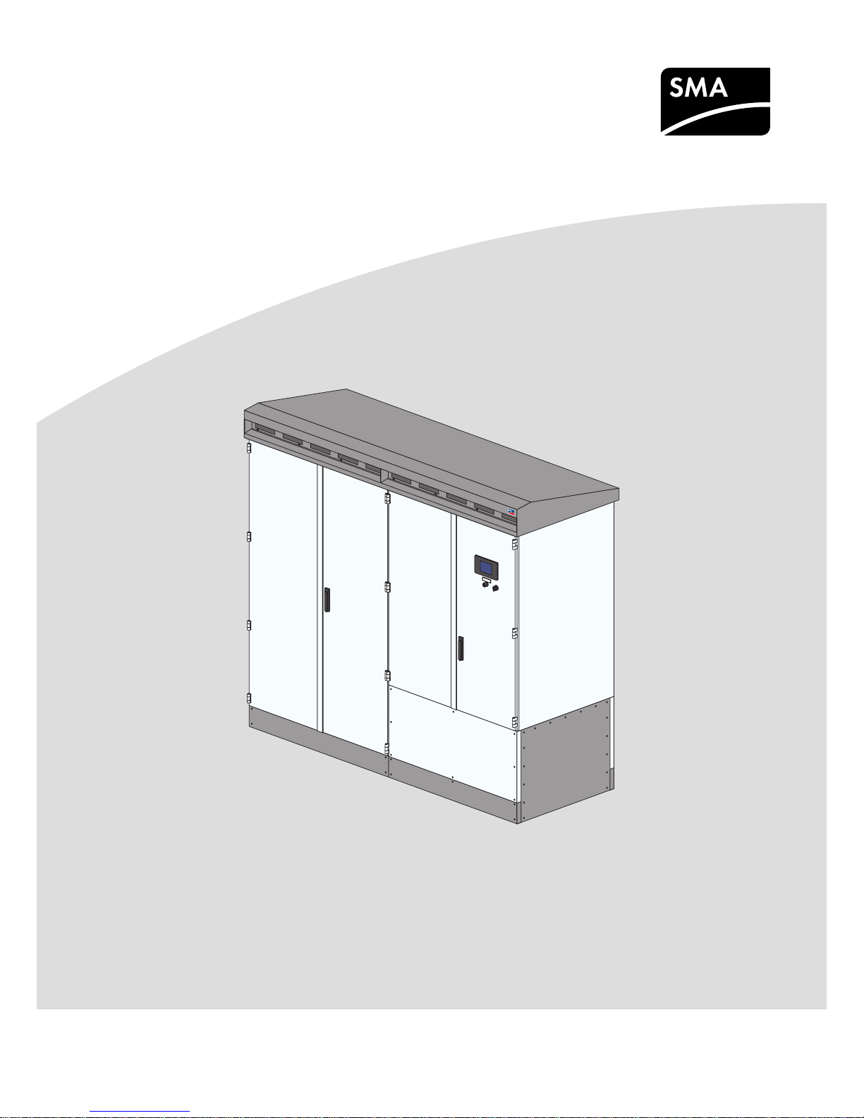
SMA SUNNY CENTRAL 630CP XT, SUNNY CENTRAL 850CP XT, SUNNY CENTRAL 720CP XT, SUNNY CENTRAL 760CP XT, SUNNY CENTRAL 900CP XT User Manual
...
SCCPXT-E7-BA-en-58 | 98-100500.08 | Version 5.8ENGLISH
User Manual
SUNNY CENTRAL 500CP XT/630CP XT/720CP XT/
760CP XT/800CP XT/850CP XT/900CP XT/1000
CP XT

Legal Provisions
SMA Solar Technology AG
User ManualSCCPXT-E7-BA-en-582
Legal Provisions
The information contained in these documents is the property of SMA Solar Technology AG. Any publication, whether
in whole or in part, requires prior written approval by SMA Solar Technology AG. Internal reproduction used solely for
the purpose of product evaluation or other proper use is allowed and does not require prior approval.
SMA Warranty
You can download the current warranty conditions from the Internet at www.SMA-Solar.com.
Software licenses
You will find the software licenses for the installed software modules on the Internet at www.SMA-Solar.com.
Trademarks
All trademarks are recognized, even if not explicitly identified as such. Missing designations do not mean that a
product or brand is not a registered trademark.
SMA Solar Technology AG
Sonnenallee 1
34266 Niestetal
Germany
Tel. +49 561 9522-0
Fax +49 561 9522-100
www.SMA.de
Email: info@SMA.de
Status: 6/20/2018
Copyright © 2018 SMA Solar Technology AG. All rights reserved.

Table of Contents
SMA Solar Technology AG
User Manual 3SCCPXT-E7-BA-en-58
Table of Contents
1 Information on this Document..................................................................................................... 9
1.1 Validity ............................................................................................................................................................. 9
1.2 Target Group ................................................................................................................................................... 9
1.3 Additional Information..................................................................................................................................... 9
1.4 Levels of warning messages............................................................................................................................ 9
1.5 Symbols in the Document................................................................................................................................ 10
1.6 Typographies in the document ....................................................................................................................... 10
1.7 Designation in the document .......................................................................................................................... 10
2 Safety ............................................................................................................................................ 11
2.1 Intended Use.................................................................................................................................................... 11
2.2 Safety Information ........................................................................................................................................... 12
2.3 Cyber Security ................................................................................................................................................. 14
2.4 Personal Protective Equipment........................................................................................................................ 15
3 Product Overview ........................................................................................................................ 16
3.1 Design of the Inverter ...................................................................................................................................... 16
3.2 Devices of the Inverter..................................................................................................................................... 16
3.3 Operating and Display Elements.................................................................................................................... 17
3.3.1 Function of the Switches .................................................................................................................................. 17
3.3.1.1 Key Switch ....................................................................................................................................................... 17
3.3.1.2 AC Disconnection Unit.................................................................................................................................... 18
3.3.1.3 DC Switchgear ................................................................................................................................................ 18
3.3.2 Touch Display................................................................................................................................................... 19
3.3.2.1 Design.............................................................................................................................................................. 19
3.3.2.2 Explanation of Symbols .................................................................................................................................. 19
3.3.3 LEDs of the SC-COM ....................................................................................................................................... 23
3.3.3.1 LEDs on the Enclosure ..................................................................................................................................... 23
3.3.3.2 LEDs on the Network Port............................................................................................................................... 24
3.3.3.3 LEDs on the Optical Fiber Terminals .............................................................................................................. 25
3.3.4 User Interface................................................................................................................................................... 26
3.3.4.1 Design of the User Interface........................................................................................................................... 26
3.3.4.2 Tree View and Device View ........................................................................................................................... 26
3.3.4.3 Status Symbols ................................................................................................................................................ 27
3.4 Symbols on the Product................................................................................................................................... 27
4 Commissioning ............................................................................................................................. 28
4.1 Safety during Commissioning ......................................................................................................................... 28
4.2 Requirements for Commissioning.................................................................................................................... 28
4.3 Visual Inspection and Mechanical Test.......................................................................................................... 29
4.3.1 Sequence for Visual Inspection and Mechanical Test................................................................................... 29
4.3.2 Checking the Connections of the Cables for Communication, Control Supply Voltage and Monitoring.. 29
4.3.3 Checking the High-Current Contacts Made at the Installation Site .............................................................. 29
4.3.4 Checking the High-Current Contacts Made at the Factory ........................................................................... 30
4.3.5 Checking the Settings of the Switching Units.................................................................................................. 30
4.3.6 Checking the Connectors ................................................................................................................................ 30
4.4 Connection and Measurement ...................................................................................................................... 30
4.4.1 Sequence for Connection and Measurement ................................................................................................ 30
4.4.2 Checking the Output Voltage of the Inverter.................................................................................................. 31
4.4.3 Checking the DC Voltage................................................................................................................................ 31
4.4.4 Switching On the Supply Voltage and the AC Disconnection Unit .............................................................. 32

Table of Contents
SMA Solar Technology AG
User ManualSCCPXT-E7-BA-en-584
4.5 Function Test..................................................................................................................................................... 33
4.5.1 Checking the Fans............................................................................................................................................ 33
4.5.2 Checking the Heating Elements and Hygrostat ............................................................................................. 33
4.6 Configuration................................................................................................................................................... 34
4.6.1 Configuring the Network Settings on the Computer...................................................................................... 34
4.6.2 Information on Integrating the Inverter into a Local Network ....................................................................... 35
4.6.3 Configuring the Inverter for a Static Network................................................................................................ 35
4.6.4 Adjusting Network Ports .................................................................................................................................. 35
4.6.5 Detecting New Devices ................................................................................................................................... 36
4.6.6 Setting the Power Limitation............................................................................................................................. 36
4.6.6.1 Setting the Active Power Ramp-Up ................................................................................................................ 36
4.6.6.2 Setting the Frequency-Dependent Active Power Limitation........................................................................... 37
4.6.6.3 Setting the Frequency-Independent Active Power Limitation ........................................................................ 37
4.6.6.4 Setting Reactive Power Control...................................................................................................................... 38
4.6.6.5 Setting Q at Night........................................................................................................................................... 38
4.6.7 Setting Grid Monitoring and Grid Limits ........................................................................................................ 39
4.6.7.1 Setting Grid Voltage Monitoring ................................................................................................................... 39
4.6.7.2 Setting Power Frequency Monitoring ............................................................................................................ 39
4.6.7.3 Activating the Manual Resume Mode ........................................................................................................... 40
4.6.8 Setting the Grid Support.................................................................................................................................. 40
4.6.8.1 Setting Full and Limited Dynamic Grid Support (FRT)................................................................................... 40
4.6.8.2 Setting Enable Islanding Detection ................................................................................................................ 40
4.6.8.3 Setting the Medium Voltage........................................................................................................................... 40
4.6.9 Setting Project-Specific Parameters ................................................................................................................. 41
4.6.9.1 Setting the Remote Shutdown ........................................................................................................................ 41
4.6.9.2 Deactivating the "Fully Hermetic" Transformer Protection ............................................................................ 41
4.6.10 Setting the String Current Monitoring ............................................................................................................ 41
4.6.10.1 Detecting the Sunny Central String-Monitor Controller and the Inverter..................................................... 41
4.6.10.2 Setting the Date and Time of the Sunny Central String-Monitor Controller ................................................ 41
4.6.10.3 Detecting the Sunny String-Monitors via the Sunny Central String-Monitor Controller.............................. 41
4.6.10.4 Redetecting the Sunny String-Monitors via the Sunny Central String-Monitor Controller .......................... 42
4.6.10.5 Detecting the Sunny String-Monitors via the Communication Unit .............................................................. 42
4.6.10.6 Adjusting the Identification of the Sunny String-Monitors............................................................................. 42
4.6.10.7 Changing the Communication Period............................................................................................................ 42
4.6.10.8 Changing the Monitoring Period................................................................................................................... 43
4.6.10.9 Assigning Strings to Different Measuring Channels...................................................................................... 43
4.6.10.10 Assigning Strings to Different Groups............................................................................................................ 43
4.6.10.11 Setting the Tripping Time ................................................................................................................................ 44
4.6.10.12 Setting the Tolerance ...................................................................................................................................... 44
4.6.11 Configuring the Zone Monitoring ................................................................................................................... 44
4.6.12 Changing System Settings via Touch Display ................................................................................................ 45
4.6.12.1 Selecting the Language.................................................................................................................................. 45
4.6.12.2 Setting the Date, Time and Time Zone........................................................................................................... 45
4.6.12.3 Selecting the Display Format.......................................................................................................................... 45
4.6.12.4 Setting the Brightness...................................................................................................................................... 45
4.6.13 Changing the System Settings via the User Interface .................................................................................... 45
4.6.13.1 Selecting the Language.................................................................................................................................. 45
4.6.13.2 Setting the Date, Time and Time Zone........................................................................................................... 46
4.6.13.3 Entering the Operator Name......................................................................................................................... 46
4.6.13.4 Changing the Password for the User Groups............................................................................................... 46
4.6.14 Configuring System Settings via XML File....................................................................................................... 47
4.6.14.1 Uploading the File custom.xml....................................................................................................................... 47
4.6.14.2 Downloading the File custom.xml.................................................................................................................. 47
4.6.14.3 Deleting the File custom.xml........................................................................................................................... 48
4.6.15 Secure Transmission of Control Commands................................................................................................... 48
4.6.15.1 Information for a Secure Transmission of Control Commands..................................................................... 48

Table of Contents
SMA Solar Technology AG
User Manual 5SCCPXT-E7-BA-en-58
4.6.15.2 Starting the automatic capture of the accepted IP addresses...................................................................... 48
4.6.15.3 Entering accepted IP addresses via the user interface ................................................................................. 48
4.6.16 Resetting the Communication Unit .................................................................................................................. 49
4.7 Switching the Inverter On................................................................................................................................ 49
5 Disconnecting and Reconnecting ................................................................................................ 50
5.1 Safety When Disconnecting and Reconnecting Voltage Sources................................................................ 50
5.2 Disconnecting the Inverter............................................................................................................................... 50
5.2.1 Switching off the Inverter ................................................................................................................................. 50
5.2.2 Disconnecting the DC Side.............................................................................................................................. 50
5.2.3 Disconnecting the AC Side.............................................................................................................................. 51
5.2.4 Disconnecting the Supply Voltage and External Voltages ............................................................................ 51
5.3 Reconnecting the Inverter................................................................................................................................ 52
5.3.1 Reconnecting the Supply Voltage and External Voltages ............................................................................. 52
5.3.2 Reconnecting the AC Side............................................................................................................................... 53
5.3.3 Reconnecting the DC Side............................................................................................................................... 53
5.3.4 Restarting the Inverter ...................................................................................................................................... 53
6 Operation ..................................................................................................................................... 54
6.1 Safety during Operation ................................................................................................................................. 54
6.2 Displaying Operating Data ............................................................................................................................ 54
6.2.1 Displaying Operating Data via the User Interface ........................................................................................ 54
6.2.2 Displaying the Operation Data via Sunny Portal........................................................................................... 54
6.2.2.1 Registering the Inverter in Sunny Portal ......................................................................................................... 54
6.2.2.2 Adjusting the PV System Identifier for Sunny Portal ...................................................................................... 55
6.2.2.3 Deleting the Sunny Portal Buffer .................................................................................................................... 55
6.3 Saving Operating Data................................................................................................................................... 55
6.3.1 Reducing Storage Capacity by Averaging .................................................................................................... 55
6.3.2 Setting the Data Transmission Frequency....................................................................................................... 55
6.3.3 Downloading Operating Data Using the FTP Server..................................................................................... 56
6.3.3.1 Defining Read and Write Access Rights ........................................................................................................ 56
6.3.3.2 Accessing the FTP Server via the Web Browser............................................................................................ 56
6.3.3.3 Activating Automatic Data Transmission via FTP Push .................................................................................. 57
6.3.4 Downloading Operating Data via HTTP Download...................................................................................... 57
6.3.4.1 Downloading Data in XML Format ................................................................................................................ 57
6.3.4.2 Downloading Data in CSV Format ................................................................................................................ 58
6.3.5 Saving Operating Data on a Memory Card ................................................................................................. 59
6.3.5.1 Information on Saving Data on a Memory Card ......................................................................................... 59
6.3.5.2 Inserting the Memory Card ............................................................................................................................ 59
6.3.5.3 Enabling Data Storage on the Memory Card .............................................................................................. 59
6.3.5.4 Displaying the Memory Capacity Available on the Memory Card ............................................................ 60
6.4 Updating the Firmware ................................................................................................................................... 60
6.4.1 Automatic Update............................................................................................................................................ 60
6.4.2 Update via User Interface ............................................................................................................................... 60
6.5 Changing the Insulation Monitoring............................................................................................................... 60
6.5.1 Insulation Monitoring with GFDI and Insulation Monitoring Device ........................................................... 60
6.5.1.1 Safety with insulation monitoring with GFDI and insulation monitoring device .......................................... 60
6.5.1.2 Switching to Insulated Operation .................................................................................................................. 61
6.5.1.3 Switching to Grounded Operation ................................................................................................................ 61
6.5.2 Insulation Monitoring with Remote GFDI and Insulation Monitoring Device............................................... 61
6.5.2.1 Information on Insulating PV Modules with Remote GFDI and Insulation Monitoring Device................... 61
6.5.2.2 Switching to Insulated Operation .................................................................................................................. 62
6.5.2.3 Switching to Grounded Operation ................................................................................................................ 62
6.6 Deleting the Device Description...................................................................................................................... 62
6.7 Sending a ZIP File with Service Information .................................................................................................. 62

Table of Contents
SMA Solar Technology AG
User ManualSCCPXT-E7-BA-en-586
7 Troubleshooting............................................................................................................................ 63
7.1 Safety during Troubleshooting........................................................................................................................ 63
7.2 Activating Alert under Fault Conditions.......................................................................................................... 63
7.3 Reading Off Disturbance Messages .............................................................................................................. 64
7.3.1 Reading Off Error Messages via Touch Display............................................................................................ 64
7.3.2 Reading Off Disturbance Messages via the User Interface .......................................................................... 64
7.3.3 Displaying the Event Report............................................................................................................................. 64
7.3.3.1 Enabling Automatic Read-Out of Events........................................................................................................ 64
7.3.3.2 Displaying and Downloading the Event Report ............................................................................................ 64
7.4 Acknowledging Disturbance Messages......................................................................................................... 65
7.4.1 Acknowledging Disturbance Messages via the Key Switch ......................................................................... 65
7.4.2 Acknowledging Disturbance Messages via the User Interface..................................................................... 65
7.5 Remedial Action in Case of Disturbances...................................................................................................... 65
7.5.1 Inverter Behavior in Case of Disturbances ..................................................................................................... 65
7.5.2 Explanation of the Error Tables....................................................................................................................... 67
7.5.3 Error Numbers 01xx to 13xx - Disturbance on the Utility Grid .................................................................... 67
7.5.4 Error Numbers 34xx to 40xx - Disturbance on the PV Array ....................................................................... 68
7.5.5 Error Numbers 6xx to 9xx - Disturbance on the Inverter............................................................................... 70
7.5.6 Displaying Disturbance Messages for Active Power Limitation .................................................................... 73
7.5.7 Displaying Disturbance Messages for the Reactive Power Setpoint ............................................................ 74
8 Disposal......................................................................................................................................... 75
9 Periodic Actions ............................................................................................................................ 76
9.1 Mounting and Disassembly Work.................................................................................................................. 76
9.1.1 Disassembling and Mounting the Panels........................................................................................................ 76
9.1.2 Disassembling and Mounting the Protective Covers...................................................................................... 77
9.2 Entering the Password via the Touch Display ................................................................................................ 78
9.3 Parameter Overview........................................................................................................................................ 78
9.3.1 Accessing the Parameter Overview ................................................................................................................ 78
9.3.2 Saving Parameter Changes............................................................................................................................. 78
9.4 User Interface................................................................................................................................................... 78
9.4.1 Logging Into the User Interface....................................................................................................................... 78
9.4.2 Logging Out of the User Interface .................................................................................................................. 79
10 Function Description..................................................................................................................... 80
10.1 Operating States ............................................................................................................................................. 80
10.1.1 Overview of the Operating States.................................................................................................................. 80
10.1.2 Stop................................................................................................................................................................... 80
10.1.3 Grid Monitoring .............................................................................................................................................. 81
10.1.3.1 Monitoring the Grid Voltage.......................................................................................................................... 81
10.1.3.2 Monitoring the Power Frequency................................................................................................................... 82
10.1.4 Grid Monitoring Time Reached....................................................................................................................... 82
10.1.5 Startup............................................................................................................................................................... 83
10.1.5.1 In Normal Operation: Active Power Ramp-Up............................................................................................. 83
10.1.5.2 After Grid Fault: Decoupling Protection Ramp.............................................................................................. 83
10.1.6 Load Operation................................................................................................................................................ 83
10.1.6.1 MPP.................................................................................................................................................................. 83
10.1.6.2 Q at Night....................................................................................................................................................... 83
10.1.7 Shutdown.......................................................................................................................................................... 84
10.1.8 Disturbance....................................................................................................................................................... 84
10.2 Safety Functions............................................................................................................................................... 84
10.2.1 Manual Shutdown Functions........................................................................................................................... 84
10.2.1.1 External Fast Stop........................................................................................................................................... 84
10.2.1.2 Remote Shutdown........................................................................................................................................... 85

Table of Contents
SMA Solar Technology AG
User Manual 7SCCPXT-E7-BA-en-58
10.2.2 Automatic Shutdown Functions ....................................................................................................................... 85
10.2.2.1 Grid Management Shutdown........................................................................................................................ 85
10.2.2.2 Transformer Protection.................................................................................................................................... 85
10.2.2.3 Active Islanding Detection.............................................................................................................................. 85
10.2.2.4 Passive Islanding Detection............................................................................................................................ 86
10.2.2.5 Behavior in Case of Increasing Temperatures .............................................................................................. 86
10.2.2.6 Switch-Off Function at Low Temperatures ..................................................................................................... 87
10.2.2.7 Low-Temperature Option................................................................................................................................ 87
10.2.3 Grounding and Insulation Monitoring............................................................................................................ 88
10.2.3.1 Mode of Operation........................................................................................................................................ 88
10.2.3.2 GFDI ................................................................................................................................................................ 88
10.2.3.3 Remote GFDI................................................................................................................................................... 89
10.2.3.4 Insulation Monitoring Device......................................................................................................................... 90
10.2.3.5 GFDI and Insulation Monitoring Device........................................................................................................ 91
10.2.3.6 Remote GFDI and Insulation Monitoring Device.......................................................................................... 92
10.3 Power Control.................................................................................................................................................. 93
10.3.1 Frequency-Dependent Active Power Limitation .............................................................................................. 93
10.3.2 Frequency-Independent Active Power Limitation............................................................................................ 94
10.3.2.1 No Active Power Limitation: Off Mode......................................................................................................... 94
10.3.2.2 Active Power Limitation with Setpoint Command via Modbus Protocol: WCtlCom Mode ....................... 94
10.3.2.3 Active Power Limitation with Absolute Value: WCnst Mode........................................................................ 94
10.3.2.4 Active Power Limitation as a Percentage of Nominal Power: WCnstNom Mode...................................... 94
10.3.2.5 Active Power Limitation via Standard Signal: WCnstNomAnIn Mode ....................................................... 94
10.3.3 Reactive Power Control ................................................................................................................................... 95
10.3.3.1 No Reactive Power Control: Off Mode......................................................................................................... 95
10.3.3.2 Reactive Power Control with Setpoint Command via Modbus Protocol: VArCtlCom Mode..................... 95
10.3.3.3 Reactive Power Control with Setpoint Command via Modbus Protocol: PFCtlCom Mode....................... 95
10.3.3.4 Reactive Power Control with Absolute Value: VArCnst Mode..................................................................... 95
10.3.3.5 Reactive Power Control as a Percentage of the Nominal Power: VArCnstNom Mode............................. 95
10.3.3.6 Reactive Power Setpoint via Standard Signal: VArCnstNomAnIn Mode................................................... 95
10.3.3.7 Reactive Power Setpoint via Displacement Power Factor cos φ: PFCnst Mode......................................... 96
10.3.3.8 Displacement Power Factor cos φ via Standard Signal: PFCnstAnIn Mode............................................... 96
10.3.3.9 Displacement Power Factor cos φ as a Function of Feed-In Power: PFCtlW Mode................................... 97
10.3.3.10 Reactive Power as a Function of the Grid Voltage: VArCtlVol Mode ......................................................... 98
10.3.3.11 Measures for Voltage Support through Parameterization of Reactive Power/Voltage Characteristic
Curve: VArCtlVolHystDb Mode ..................................................................................................................... 98
10.3.3.12 Measures for Voltage Support through Parameterization of Reactive Power/Voltage Characteristic
Curve: VArCtlVolHystDbA Mode .................................................................................................................. 101
10.3.4 Q at Night ........................................................................................................................................................102
10.3.4.1 No Q at Night: Off Mode............................................................................................................................. 102
10.3.4.2 Q at Night with Operation Command via Modbus Protocol: VArCtlCom Mode...................................... 102
10.3.4.3 Q at Night with Absolute Value: VArCnst Mode.......................................................................................... 102
10.3.4.4 Q at Night as a Percentage of the Nominal Power: VArCnstNom Mode ................................................. 102
10.3.4.5 Q at Night via Standard Signal: VArCnstNomAnIn Mode......................................................................... 102
10.3.4.6 Q at Night Depending on the Grid Voltage: VArCtlVol Mode................................................................... 103
10.3.4.7 Measures for Voltage Support through Parameterization of Reactive Power/Voltage Characteristic
Curve: VArCtlVolHystDb Mode ..................................................................................................................... 104
10.3.4.8 Measures for Voltage Support through Parameterization of Reactive Power/Voltage Characteristic
Curve: VArCtlVolHystDbA Mode .................................................................................................................. 106
10.3.5 Behavior in the Absence of Active and Reactive Power Setpoints................................................................107
10.4 Structure of the Communication Network......................................................................................................108
10.5 Grid Management Services............................................................................................................................ 110
10.5.1 Requirements for Grid Management Services ...............................................................................................110
10.5.2 Dynamic Grid Support (FRT) ...........................................................................................................................110
10.5.2.1 Full and Limited Dynamic Grid Support (FRT)............................................................................................... 110
10.5.2.2 Grid Support in Case of Untervoltage (LVRT)............................................................................................... 111

Table of Contents
SMA Solar Technology AG
User ManualSCCPXT-E7-BA-en-588
10.5.2.3 Dynamic Undervoltage Detection.................................................................................................................. 112
10.5.2.4 Grid Support in the Event of Overvoltage (HVRT)........................................................................................ 113
10.6 Zone Monitoring.............................................................................................................................................. 114
11 Operating Data and Parameters ................................................................................................ 115
11.1 Operating Data ...............................................................................................................................................115
11.1.1 Inverter..............................................................................................................................................................115
11.1.1.1 Power Limitation.............................................................................................................................................. 115
11.1.1.2 Error Channels................................................................................................................................................. 117
11.1.1.3 Measured Values............................................................................................................................................ 117
11.1.1.4 Internal Device Values.................................................................................................................................... 117
11.1.1.5 Internal Meters................................................................................................................................................ 118
11.1.1.6 Service-Relevant Displays............................................................................................................................... 118
11.1.2 Sunny Central String-Monitor Controller ........................................................................................................119
11.1.2.1 Instantaneous Values...................................................................................................................................... 119
11.1.2.2 Internal Device Values.................................................................................................................................... 119
11.1.2.3 Status Values................................................................................................................................................... 119
11.1.3 Sunny String-Monitor .......................................................................................................................................119
11.1.3.1 Instantaneous Values...................................................................................................................................... 119
11.1.3.2 Internal Device Values.................................................................................................................................... 119
11.1.3.3 Status Values................................................................................................................................................... 120
11.1.4 Zone Monitoring ..............................................................................................................................................120
11.1.4.1 Instantaneous Values...................................................................................................................................... 120
11.1.4.2 Status Values................................................................................................................................................... 120
11.2 Parameters ......................................................................................................................................................121
11.2.1 Inverter..............................................................................................................................................................121
11.2.1.1 Power Limitation.............................................................................................................................................. 121
11.2.1.2 Grid Monitoring and Grid Limits.................................................................................................................... 133
11.2.1.3 Grid Support................................................................................................................................................... 135
11.2.1.4 Insulation monitoring....................................................................................................................................... 137
11.2.1.5 Project-Specific Parameters............................................................................................................................. 138
11.2.2 Sunny Central String-Monitor Controller ........................................................................................................140
11.2.3 Sunny String-Monitor .......................................................................................................................................142
11.2.4 Zone Monitoring ..............................................................................................................................................143
12 Appendix ......................................................................................................................................145
12.1 Information for Installation ..............................................................................................................................145
12.1.1 Minimum Clearances.......................................................................................................................................145
12.1.1.1 Minimum Clearances for Outdoor Installation.............................................................................................. 145
12.1.1.2 Minimum Clearances in Electrical Equipment Rooms................................................................................... 147
12.2 Type Label........................................................................................................................................................ 149
12.3 XML File custom.xml ........................................................................................................................................149
12.3.1 Structure of the XML File custom.xml...............................................................................................................149
12.3.2 Parameters and Values for the File custom.xml..............................................................................................150
13 Contact ..........................................................................................................................................153

1 Information on this Document
SMA Solar Technology AG
User Manual 9SCCPXT-E7-BA-en-58
1 Information on this Document
1.1 Validity
This document is valid for the following device types:
Device type Production version OCU firmware
version
DSP firmware
version
SC500CP‑10 (SunnyCentral500CPXT) E7 02.00.01.R 02.00.01.R
SC630CP‑10 (SunnyCentral630CPXT)
SC720CP‑10 (SunnyCentral720CPXT)
SC760CP‑10 (SunnyCentral760CPXT)
SC800CP‑10 (SunnyCentral800CPXT)
SC850CP‑10 (SunnyCentral850CPXT)
SC900CP‑10 (SunnyCentral900CPXT)
SC1000CP‑10 (SunnyCentral1000CPXT)
The production version is indicated on the type label.
The firmware version can be read off from the user interface.
Illustrations in this document are reduced to the essential and may deviate from the real product.
1.2 Target Group
The tasks described in this document must only be performed by qualified persons. Qualified persons must have the
following skills:
• Knowledge of how the product works and is operated
• Training in how to deal with the dangers and risks associated with installing and using electrical devices and
systems
• Training in the installation and commissioning of electrical devices and systems
• Knowledge of all applicable standards and directives
• Knowledge of and adherence to this manual and all safety precautions
1.3 Additional Information
For more information, please go to www.SMA-Solar.com.
Title and information content Type of information
"PUBLIC CYBER SECURITY - Guidelines for a Secure PV System Communication" Technical information
1.4 Levels of warning messages
The following levels of warning messages may occur when handling the product.
DANGER
Indicates a hazardous situation which, if not avoided, will result in death or serious injury.
1 Information on this Document
SMA Solar Technology AG
User ManualSCCPXT-E7-BA-en-5810
WARNING
Indicates a hazardous situation which, if not avoided, could result in death or serious injury.
CAUTION
Indicates a hazardous situation which, if not avoided, could result in minor or moderate injury.
NOTICE
Indicates a situation which, if not avoided, can result in property damage.
1.5 Symbols in the Document
Symbol Explanation
Information that is important for a specific topic or goal, but is not safety-relevant
☐
Indicates a requirement for meeting a specific goal
☑
Desired result
✖
A problem that might occur
1.6 Typographies in the document
Typography Use Example
bold
• Messages
• Terminals
• Elements on a user interface
• Elements to be selected
• Elements to be entered
• Connect the insulated conductors
to the terminals X703:1 to
X703:6.
• Enter 10 in the field Minutes.
>
• Connects several elements to be
selected
• Select Settings > Date.
[Button]
[Key]
• Button or key to be selected or pressed
• Select [Enter].
1.7 Designation in the document
Complete designation Designation in this document
SunnyCentral Inverter
SunnyCentralCommunicationController SC-COM or communication unit

2 Safety
SMA Solar Technology AG
User Manual 11SCCPXT-E7-BA-en-58
2 Safety
2.1 Intended Use
The SunnyCentral is a PV inverter which converts the direct current generated in the PV modules into grid-compliant
alternating current. An external MV transformer fitted downstream feeds the generated alternating current into the
utility grid.
The product is suitable for indoor and outdoor use.
The enclosure complies with degree of protection IP54. The inverter is classified under Class4C2 as per
EN60721-3-4 and is suitable for operation in a chemically active environment.
The maximum permissible DC input voltage of the inverter must not be exceeded.
The inverter must only be operated in conjunction with a suitable MV transformer.
• The MV transformer must be designed for voltages that arise during pulsed mode of the inverter.
• For the SunnyCentral 500CPXT/630CPXT/720CPXT/760CPXT/800CPXT the maximum voltage to ground is:
±1450V
• For the SunnyCentral 850CPXT/900CPXT/1000CPXT the maximum voltage to ground is: ±1600V
• Do not connect more than one inverter to one winding of the MVtransformer.
• The neutral conductor on the low-voltage side of the MV transformer must not be grounded.
You can find further information on suitable transformers in the technical information "Requirements for MediumVoltage Transformers and Transformers for Internal Power Supply for the SUNNYCENTRAL".
Do not deactivate or modify settings that affect grid management services without first obtaining approval from the grid
operator.
Use this product only in accordance with the information provided in the enclosed documentation and with the locally
applicable standards and directives. Any other application may cause personal injury or property damage.
Alterations to the product, e.g. changes or modifications, are only permitted with the express written permission of
SMA Solar Technology AG. Unauthorized alterations will void guarantee and warranty claims and in most cases
terminate the operating license. SMA Solar Technology AG shall not be held liable for any damage caused by such
changes.
Any use of the product other than that described in the Intended Use section does not qualify as the intended use.
The enclosed documentation is an integral part of this product. Keep the documentation in a convenient place for
future reference and observe all instructions contained therein.
All work on the product must only be performed using appropriate tools and in compliance with the ESD protection
regulations.
Suitable personal protective equipment must be worn by all persons working on or with the product.
Unauthorized persons must not operate the product and must be kept at a safe distance from the product.
The product must not be operated with open covers or doors.
The product must not be opened when it is raining or when humidity exceeds 95%.
The product must not be operated with any technical defects.
The type label must remain permanently attached to the product.
2 Safety
SMA Solar Technology AG
User ManualSCCPXT-E7-BA-en-5812
2.2 Safety Information
This section contains safety information that must be observed at all times when working on or with the product. To
prevent personal injury and property damage and to ensure long-term operation of the product, read this section
carefully and observe all safety information at all times.
DANGER
Danger to life from electric shock due to live voltage
High voltages are present in the live components of the product. Touching live components results in death or
serious injury due to electric shock.
• Wear suitable personal protective equipment for all work on the product.
• Do not touch any live components.
• Observe all warning messages on the product and in the documentation.
• Observe all safety information of the module manufacturer.
• After switching off the inverter, wait at least 15minutes before opening it to allow the capacitors to discharge
completely (see Section5.2, page50).
DANGER
Danger to life from electric shock due to live DC cables
DC cables connected to PV modules that are exposed to sunlight carry live voltage. Touching live cables results in
death or serious injury due to electric shock.
• Prior to connecting the DC cables, ensure that the DC cables are voltage-free.
• Wear suitable personal protective equipment for all work on the device.
DANGER
Danger to life from electric shock due to ground fault
If a ground fault has occurred, parts of the PV power plant that are supposedly grounded may in fact be live.
Touching incorrectly grounded parts of the PV power plant results in death or serious injuries from electric shock.
• Before working on the PV power plant, ensure that no ground fault is present.
• Wear suitable personal protective equipment for all work on the device.
DANGER
Danger to life from electric shock due to damaged product
Operating a damaged product can lead to hazardous situations that result in death or serious injuries due to
electric shock.
• Only operate the product when it is in a flawless technical condition and safe to operate.
• Check the product regularly for visible damage.
• Make sure that all external safety equipment is freely accessible at all times.
• Make sure that all safety equipment is in good working order.
• Wear suitable personal protective equipment for all work on the product.
2 Safety
SMA Solar Technology AG
User Manual 13SCCPXT-E7-BA-en-58
DANGER
Danger to life from electric shock even if the inverter is disconnected on the AC and DC sides
The precharge unit of the order option "QatNight" will carry live voltage even if the AC disconnection unit and the
DC switchgear are open. Touching live components results in death or serious injury due to electric shock.
• Do not touch any live components.
• Switch off the inverter.
• After switching off the inverter, wait at least 15minutes before opening it to allow the capacitors to discharge
completely.
• Ensure that no voltage is present.
• Do not remove protective covers.
• Observe the warning messages.
• Wear suitable personal protective equipment for all work on the product.
WARNING
Danger to life from electric shock when entering the PV field
Ground-fault monitoring does not provide protection from personal injury. PV modules which are grounded with
ground-fault monitoring discharge voltage to ground. Entering the PV field can result in lethal electric shocks.
• Ensure that the insulation resistance of the PV field exceeds the minimum value. The minimum value of the
insulation resistance is: 1 kΩ.
• Before entering the PV field, switch the PV modules to insulated operation.
• Configure the PV power plant as a closed electrical operating area.
WARNING
Danger to life from electric shock if the product is not locked
If the product is not locked, unauthorized persons will have access to live components carrying lethal voltages.
Touching live components can result in death or serious injury due to electric shock.
• Always close and lock the product.
• Remove the keys.
• Store the keys in a safe place.
• Ensure that no unauthorized persons have access to the closed electrical operating area.
WARNING
Danger to life due to blocked escape routes
In hazardous situations, blocked escape routes can lead to death or serious injury. Opening the doors of two
products located opposite each other can block the escape route. It is imperative that the escape route is freely
accessible at all times.
• An escape route must be available at all times. Make sure the minimum passage width of the escape route
meets local standards.
• Do not place any objects in the escape route area.
• Remove all tripping hazards from escape routes.
2 Safety
SMA Solar Technology AG
User ManualSCCPXT-E7-BA-en-5814
CAUTION
Risk of burns due to hot components
Some components of the product can get very hot during operation. Touching these components can cause burns.
• Observe the warnings on all components.
• During operation, do not touch any components marked with such warnings.
• After switching off the product, wait until any hot components have cooled down sufficiently.
• Wear suitable personal protective equipment for all work on the product.
NOTICE
Property damage due to dust intrusion and moisture penetration
Dust or moisture intrusion can damage the product and impair its functionality.
• Do not open the enclosure during rainfall or when humidity exceeds the specified thresholds. The humidity
thresholds are: 15%to95%.
• Only perform maintenance work when the environment is dry and free of dust.
• Operation of the product is only permitted when it is closed.
• Connect the external supply voltage after mounting and installing the product.
• If the installation or commissioning process is interrupted, mount all panels.
• Close and lock the enclosure.
• The product must always be closed for storage.
• Store the product in a dry and covered location.
• Temperature at the storage location must be in the specified range. The temperature range is:
−25°Cto+70°C.
NOTICE
Damage to electronic components due to electrostatic discharge
Electrostatic discharge can damage or destroy electronic components.
• Observe the ESD safety regulations when working on the product.
• Wear suitable personal protective equipment for all work on the product.
• Discharge electrostatic charge by touching grounded enclosure parts or other grounded elements. Only then is
it safe to touch electronic components.
2.3 Cyber Security
Most operating activities such as monitoring and control of PV systems can be done locally by the PV system operator
or service personnel without the need for data communication via public Internet infrastructure. These operating
activities, including data communication between PV system operator/service personnel and PV inverter, data logger
or additional equipment, can be accessed by using local displays, keypads or using local access of the webserver of a
device in the LAN of the PV system or of the building.
In other use cases of PV systems, the PV systems are also part of the global communication system, which is based on
Internet infrastructures.
The data communication via Internet is an up-to-date, economically viable and customer-friendly approach in order to
enable easy access for the following modern applications such as:
• Cloud platforms (e.g. SunnyPortal)
• Smartphones or other mobile devices (iOS or Android apps)

2 Safety
SMA Solar Technology AG
User Manual 15SCCPXT-E7-BA-en-58
• SCADA systems, which are remotely connected
• Utility interfaces for grid management services
Alternatively, selected and secured communication interfaces may be used. These solutions are no longer state of the
art and are very expensive to use (special communication interfaces, separate wide area networks and more).
When using the Internet infrastructure, the systems connected to the Internet are entering a basically unsecure area.
Potential attackers constantly seek vulnerable systems. Usually, they are criminally motivated, have a terrorist
background or aim to disrupt business operations. Without taking any measures to protect PV systems and other
systems from such misuse, a data communication system should not be connected to the Internet.
You can find the current recommendations by SMA Solar Technology AG on the topic Cyber Security in the Technical
Information "PUBLIC CYBER SECURITY - Guidelines for a Secure PV System Communication" at www.SMA-Solar.com.
2.4 Personal Protective Equipment
Always wear suitable protective equipment
When working on the product, always wear the appropriate personal protective equipment for the specific job.
The following personal protective equipment is regarded to be the minimum requirement:
☐ In a dry environment, safety shoes of categoryS3 with perforation-proof soles and steel toe caps
☐ During precipitation or on moist ground, safety boots of categoryS5 with perforation-proof soles and steel toe
caps
☐ Tight-fitting work clothes made of 100%cotton
☐ Suitable work pants
☐ Individually fitted hearing protection
☐ Safety gloves
Any other prescribed protective equipment must also be used.
3 Product Overview
SMA Solar Technology AG
User ManualSCCPXT-E7-BA-en-5816
3 Product Overview
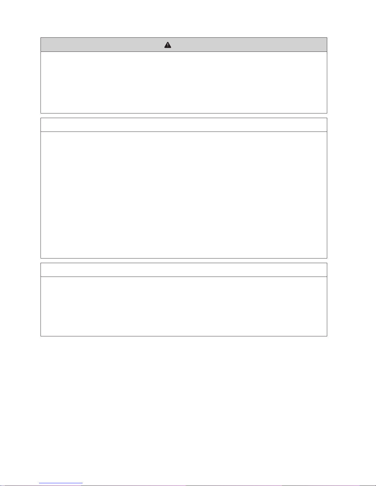
3.1 Design of the Inverter
Figure 1: Design of the Inverter
Position Designation
A Inverter cabinet
B Interface cabinet
C Connection area
3.2 Devices of the Inverter
Figure 2: Devices of the inverter
Position Device Description
A Touch display Different kinds of inverter data can be viewed on the touch display. The
touch display is only used to view data. The display screen is activated by
touching the touch display.
B Service interface The service interface allows access to the user interface.
C Key switch The key switch is used to switch the inverter on and off.
3 Product Overview
SMA Solar Technology AG
User Manual 17SCCPXT-E7-BA-en-58
Position Device Description
D DC switchgear The DC switchgear disconnects the inverter from the PV array.
E SC-COM The SC-COM is the communication unit of the inverter. The SC-COM estab-
lishes the connection between the inverter and the system operator.
F AC disconnection unit The AC disconnection unit disconnects the inverter from the MVtrans-
former.
3.3 Operating and Display Elements
3.3.1 Function of the Switches
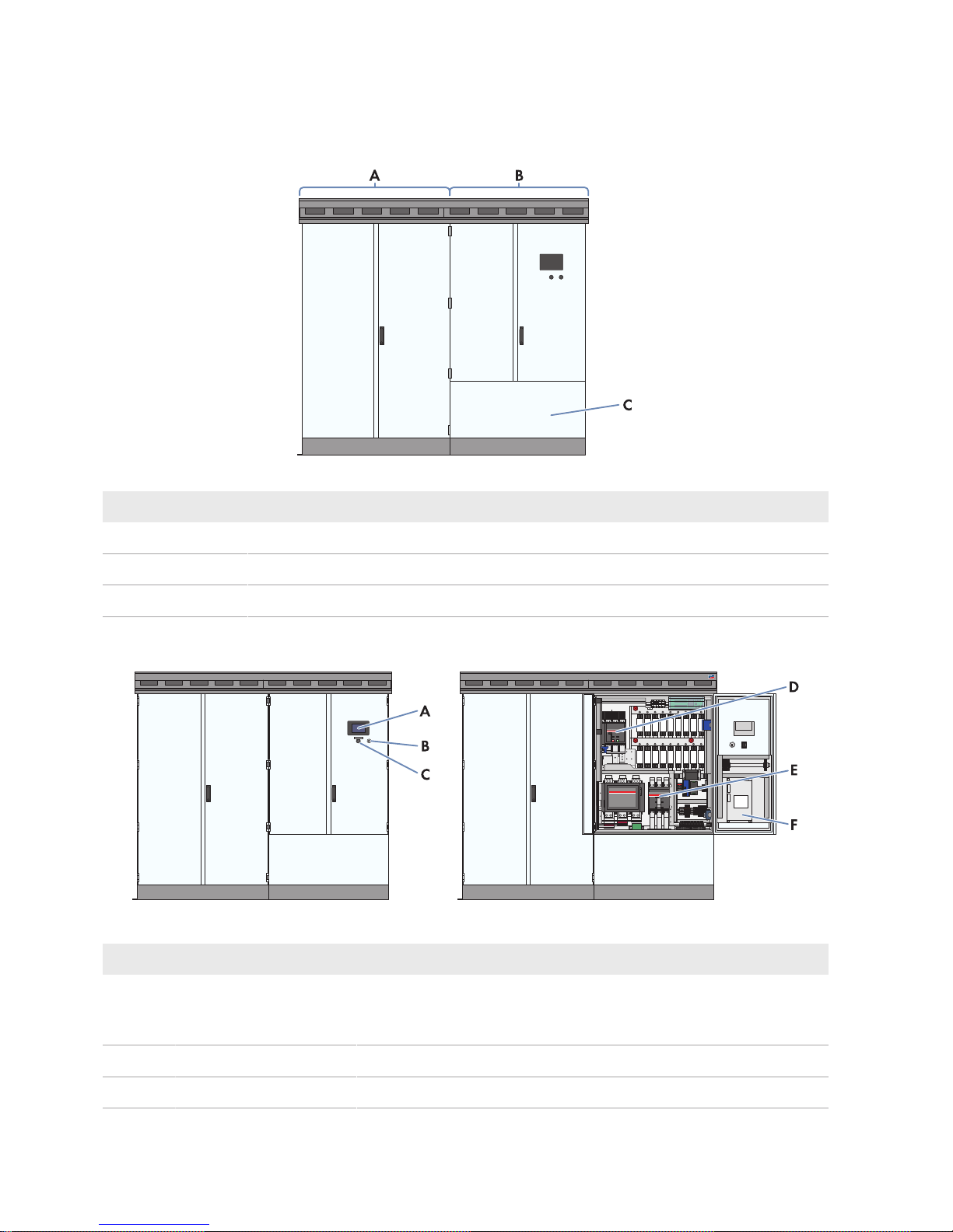
3.3.1.1 Key Switch
The key switch is used to switch the inverter on and off.
Figure 3: Switch positions of the key switch
Position Designation
A
Switch position Stop
B
Switch position Start
Switch position "Start"
If the key switch is turned to Start, a motor drive switches the DC switchgear on and the inverter switches from the
operating state "Stop" to the operating state "Grid monitoring". Provided that there is sufficient irradiation and a valid
utility grid connection, the inverter switches to feed-in operation. If there is insufficient irradiation and the input voltage
is therefore too low, the inverter remains in the operating state "Grid monitoring".
Switch position "Stop"
If the key switch is turned to Stop while the inverter is in the operating state "Grid monitoring", a motor drive switches
the DC switchgear off. The inverter switches to the operating state "Stop". If the key switch is turned to Stop while the
inverter is in the operating state "MPP load operation", the inverter switches to the operating state "Shutdown". Once
shutdown is complete, the AC disconnection unit and the DC switchgear are opened automatically and the inverter
switches to the operating state "Stop".
3 Product Overview
SMA Solar Technology AG
User ManualSCCPXT-E7-BA-en-5818
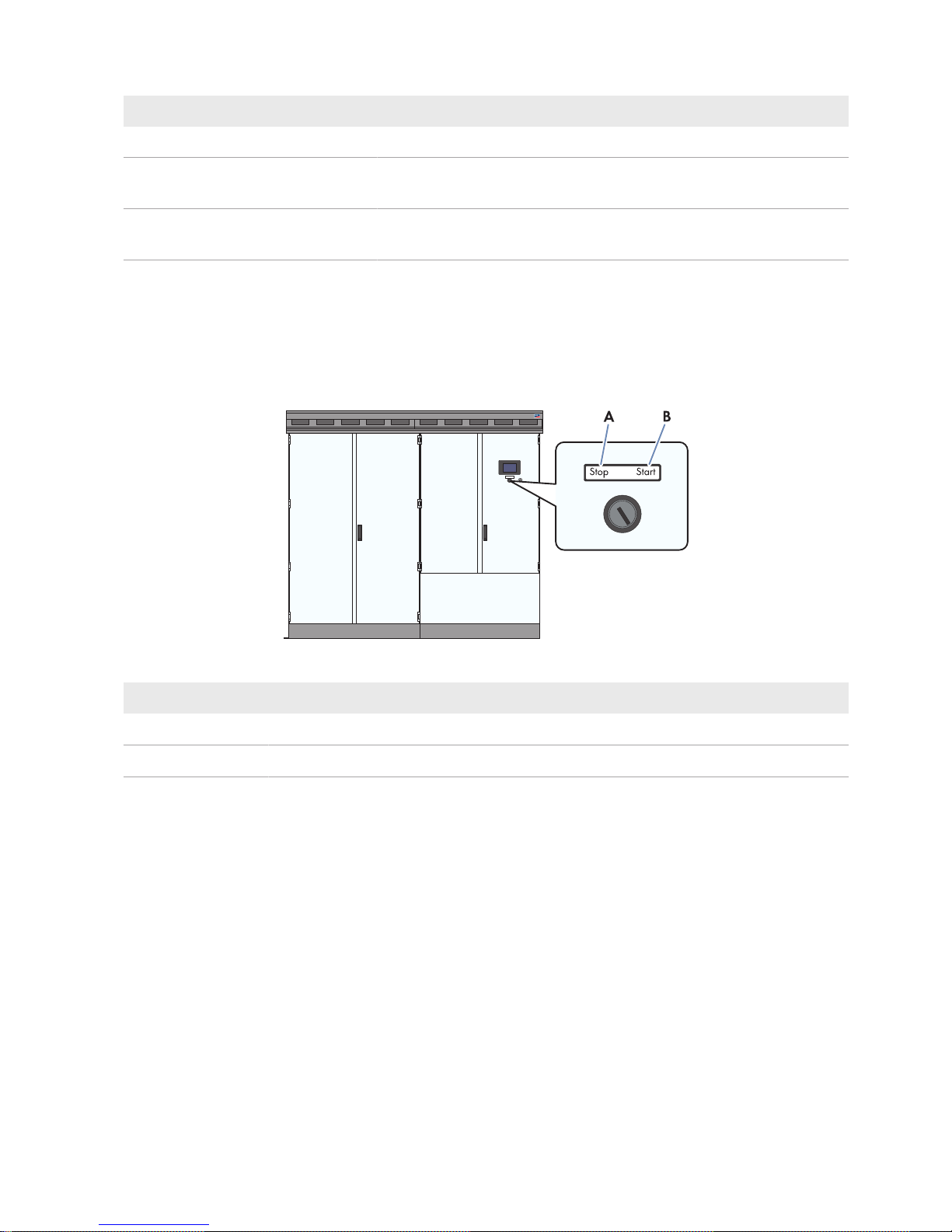
3.3.1.2 AC Disconnection Unit
The AC disconnection unit disconnects the inverter from the MV transformer.
Figure 4: Switch positions of the AC disconnection unit from ABB
Position Designation Explanation
A
Switch position on
The AC disconnection unit is closed.
B Central switch position The AC disconnection unit was tripped and is open.
C
Switch position off
The AC disconnection unit is open.
3.3.1.3 DC Switchgear
The DC switchgear disconnects the inverter from the PV power plant.
Figure 5: Indicators on the DC load-break switch
Position Designation
A Spring status indicator
B Position indicator
C ON button
D OFF button
3 Product Overview
SMA Solar Technology AG
User Manual 19SCCPXT-E7-BA-en-58
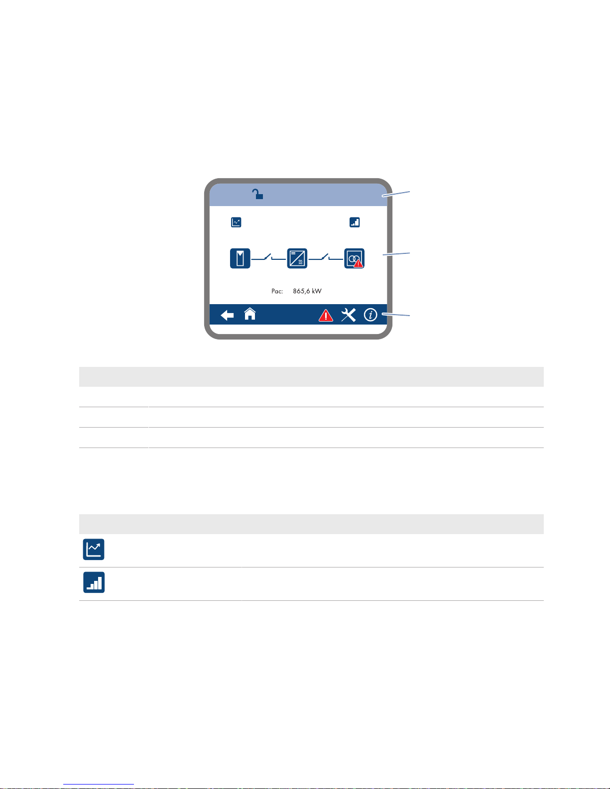
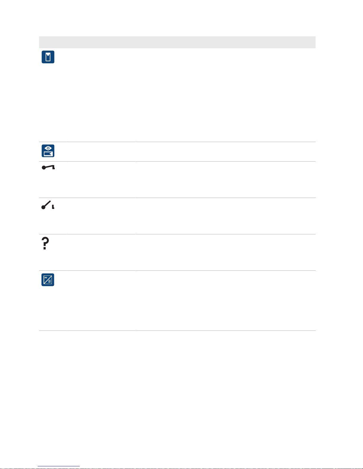
3.3.2 Touch Display
3.3.2.1 Design
The touch display is used to display instantaneous values and parameter settings. Tapping the symbols on the touch
display activates the corresponding functions. If the touch display has not been touched for five minutes, the display is
locked and the logged-in user will be logged out. By tapping the characters "S", "M" or "A", you can unlock the display
again.
The touch display is divided into three areas.
100
DD.MM.YYYY-hh:mm:ss
A
B
C
Figure 6: Design of the touch display
Position Designation Explanation
A Status info line Number of the active menu, login status and time
B Information field Area of the main menu
C Navigation line Navigation area
3.3.2.2 Explanation of Symbols
Information field
You can access the following sub-menus and screens from the information field:
Symbol Designation Explanation
E-today line graph Diagram 103: Representation of energy fed in during the current day in
kWh.
Bar chart Diagram 104: Representation of energy fed in during the last 14days in
kWh.
3 Product Overview
SMA Solar Technology AG
User ManualSCCPXT-E7-BA-en-5820
Symbol Designation Explanation
DC side Representation of the instantaneous values
• PV power in W
• Insulation resistance in Ω
• PV current in A
• PV voltage in V
• Diagram of string-current monitoring
– Diagram 132 to 133: Group currents of the individual Sunny
String‑Monitors
– Diagram 140 to 146: String currents of the individual Sunny
String‑Monitors
String-current monitoring of
the DC side
Representation of the instantaneous values of the string-current monitoring
of the individual Sunny String-Monitors
Switch on DC or AC side
closed
If you see this symbol between the "DC side" symbol and the "Inverter
data" symbol, the DC switchgear is closed.
If you see this symbol between the symbol "Inverter data" and the symbol
"AC side", the AC contactor is closed.
Switch on DC or AC side
open
If you see this symbol between the "DC side" symbol and the "Inverter
data" symbol, the DC switchgear is open.
If you see this symbol between the symbol "Inverter data" and the symbol
"AC side", the AC contactor is open.
Status of switches on DC or
AC side unknown
If you see this symbol between the "DC side" symbol and the "Inverter
data" symbol, the switch status of the DC switchgear is not known.
If you see this symbol between the symbol "Inverter data" and the symbol
"AC side", the switch status of the AC contactor is unknown.
Inverter data Representation of the following inverter data:
• Device type
• Operating state
• Symbol for utility grid menu
• Symbol for temperature display
• Symbol for fan display
3 Product Overview
SMA Solar Technology AG
User Manual 21SCCPXT-E7-BA-en-58
Symbol Designation Explanation
AC side Representation of the following instantaneous values:
• Active power in W
• Reactive power in VAr
• Power frequency in Hz
• AC current in A
• AC voltage in V
grid First menu page:
• Active mode of active power limitation
• Target active power in kW
• Actual active power in kW
Second menu page
• Active mode of reactive power setpoint
• Target reactive power in VAr
• Target displacement power factor cos φ
• Target excitation type of the displacement power factor
• Actual reactive power in VAr
• Actual displacement power factor cos φ
• Actual excitation type of the displacement power factor
Settings Menu
Symbol Designation Explanation
Language selection Select this symbol to open the language selection menu.
Brightness setting Select this symbol to open the brightness setting menu.
Time setting Select this symbol to open the time setting menu.
Format selection Select this symbol to open the format selection menu.
Password entry Select this symbol to open the password entry menu.
Navigation line
Symbol Designation Explanation
Back Select this symbol to go back to the previous page.
Homepage Select this symbol to go to the homepage.

3 Product Overview
SMA Solar Technology AG
User ManualSCCPXT-E7-BA-en-5822
Symbol Designation Explanation
Settings • Language selection
• Brightness setting
• Time setting
• Format selection
• Password entry
Information • OS: version of the operating system
• App.: version of the application software
• SC-COM version: SC-COM software version
• Ser.No.: inverter serial number
• Hardware: hardware version and serial number of the SC-COM
Error • ErrNo: error number
• TmsRmg: time until reconnection
• Msg: error message
• Dsc: corrective measure
Service • Telephone receiver: Contact Service.
• Tool: Contact your installer.
3 Product Overview
SMA Solar Technology AG
User Manual 23SCCPXT-E7-BA-en-58
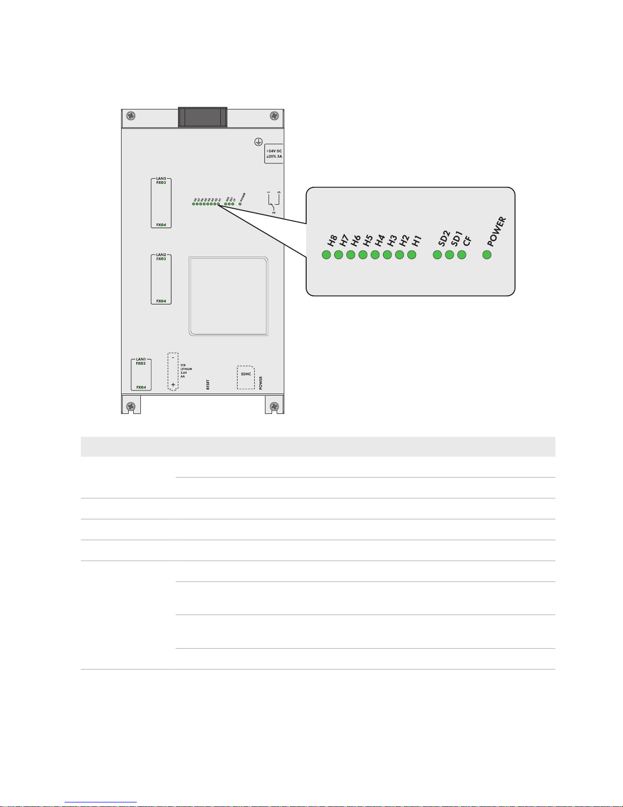
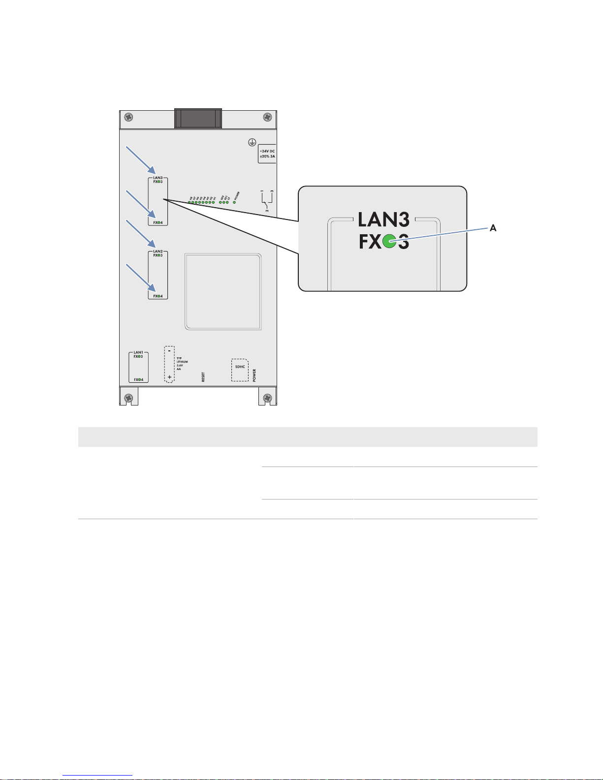
3.3.3 LEDs of the SC-COM
3.3.3.1 LEDs on the Enclosure
Figure 7: LEDs on the enclosure
LED designation Status Explanation
POWER glowing green The SC-COM is supplied with voltage.
off The SC-COM is not supplied with voltage.
SD1 flashing green Read or write access to system drive
SD2 flashing green Read or write access to internal data drive
CF flashing green Read or write access to external SD memory card
H1 flashing green The SC-COM is transmitting data to Sunny Portal/FTP server.
glowing green The most recent data transmission to Sunny Portal/FTP server was
successful.
glowing red The most recent data transmission to Sunny Portal/FTP server has
failed.
off Data transmission to Sunny Portal/FTP server is deactivated.
3 Product Overview
SMA Solar Technology AG
User ManualSCCPXT-E7-BA-en-5824
LED designation Status Explanation
H2 flashing green The SC-COM is communicating with the devices connected within the
system.
glowing green Internal communication has taken place in the last five minutes.
glowing red An error has occurred in the internal communication.
off No internal communication for more than five minutes.
H3 flashing red The SC-COM is starting up.
glowing red An error has occurred in the SC-COM.
glowing green The SC-COM is ready for use.
H4 glowing green An internal memory card exists and less than 92% of its storage ca-
pacity is used.
glowing red The internal memory card is full and the oldest saved data is being
overwritten.
flashing red 92% of the storage capacity of the internal memory card is used.
H5 glowing green An external memory card exists and less than 92% of its storage ca-
pacity is used.
glowing red The external memory card is full.
flashing red 92% of the storage capacity of the external memory card is used.
off There is no external memory card.
H6 - Not assigned
H7 - Not assigned
H8 flashing green Application is running.
3.3.3.2 LEDs on the Network Port
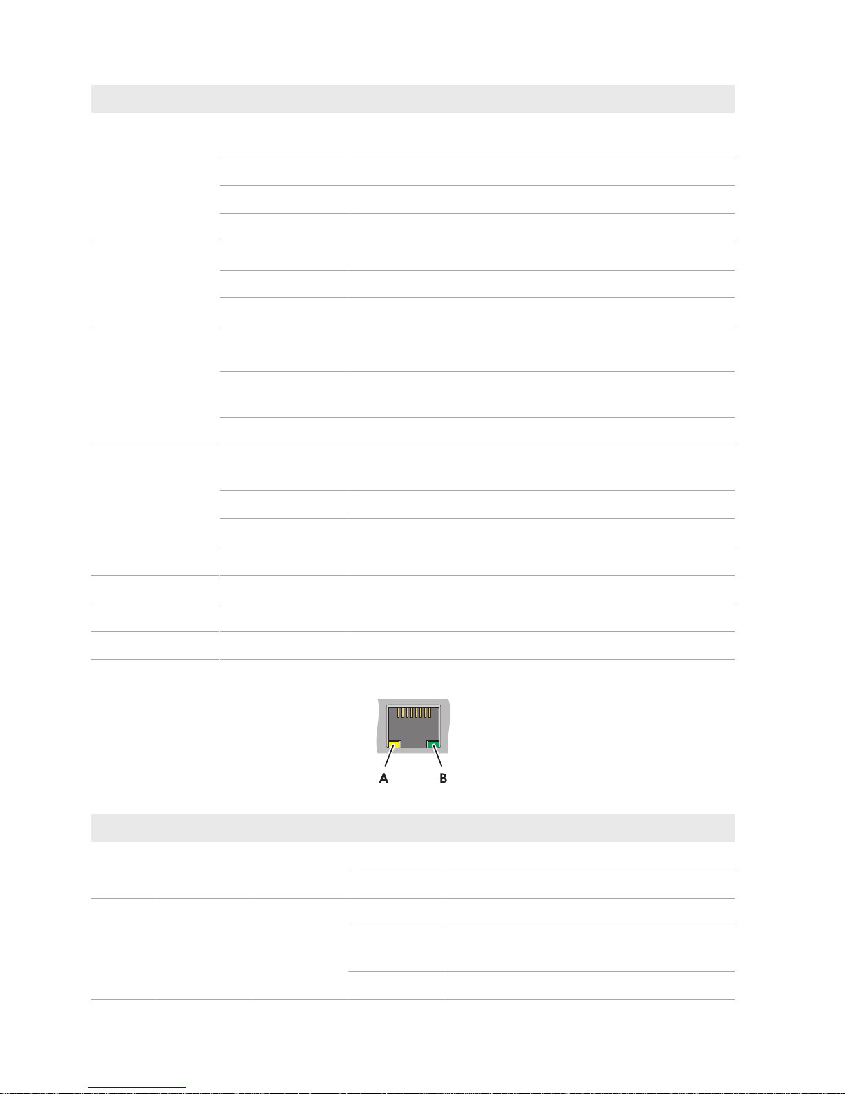
Figure 8: LEDs on the network port
Position LED Color Status Explanation
A Speed yellow on 100 MBit data transfer rate
off 10 MBit data transfer rate
B Link/Activity green on Connection (Link) established.
flashing The SC-COM is transmitting or receiving data (Ac-
tivity).
off No connection established.
3 Product Overview
SMA Solar Technology AG
User Manual 25SCCPXT-E7-BA-en-58
3.3.3.3 LEDs on the Optical Fiber Terminals
The SC-COM is also available with pre-wired optical fiber connections. If the optical fibers are connected to the splice
box of the inverter, the status of the connection will be indicated by the LEDs of the SC-COM.
Figure 9: LEDs for the status of the optical fiber connection
Position LED Color Status Explanation
A Link / Activity green on Connection (Link) established.
flashing The SC-COM is transmitting or receiving data
(Activity).
off No connection established.
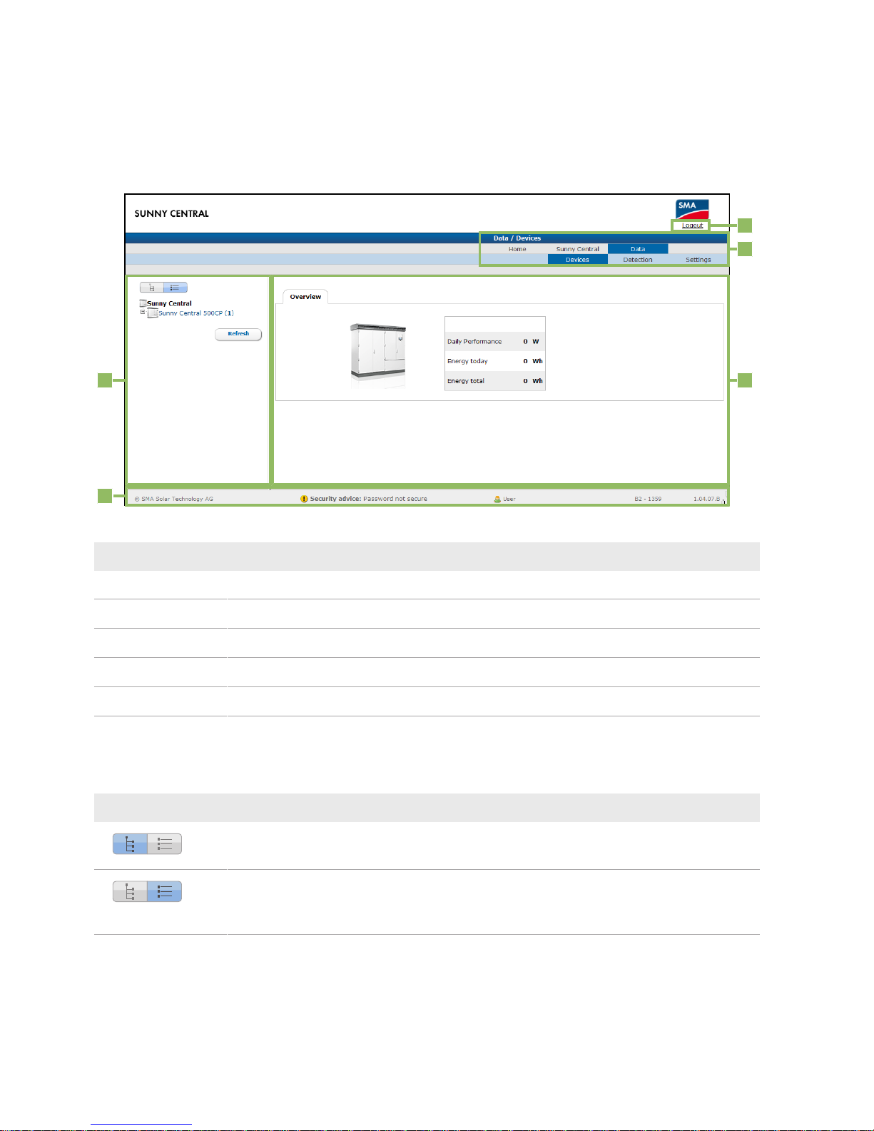
3 Product Overview
SMA Solar Technology AG
User ManualSCCPXT-E7-BA-en-5826
3.3.4 User Interface
3.3.4.1 Design of the User Interface
Via the user interface, you can set the communication of the devices of your PV power plant, configure the inverter
parameters and read off error messages and operating data.
A
B
C
D
E
Figure 10: Design of the user interface (example)
Position Designation
A Tree view or device view
B Status bar
C Logout button
D Navigation bar
E Content area
3.3.4.2 Tree View and Device View
You can call up data of the individual devices of your PV power plant in the tree view or the device view. Depending
on which view you have selected, the devices are sorted differently.
Symbol Designation Explanation
Tree view In the tree view, the user interface shows the devices in the or-
der in which they are connected to the data bus.
Device view In the device view, the user interface shows all devices sorted
by device type. The number shown in parentheses indicates the
number of devices of a device type.
3 Product Overview
SMA Solar Technology AG
User Manual 27SCCPXT-E7-BA-en-58
3.3.4.3 Status Symbols
Depending on the status of the device communication, the device symbols are displayed in the tree or device view with
various status symbols.
Symbol Explanation
The inverter is ready for operation.
There is an error in the inverter.
An error has occurred in the communication with the inverter.
3.4 Symbols on the Product
The following gives an explanation of all the symbols found on the inverter and on the type label.
Symbol Designation Explanation
CE marking The product complies with the requirements of the applicable EU di-
rectives.
Protection classI All electrical equipment is connected to the grounding conductor sys-
tem of the product.
Degree of protectionIP54 The product is protected against interior dust deposits and splashing
water from all angles.
Beware of a danger zone This warning symbol indicates a danger zone. Be particularly vigilant
and cautious when working on the product.
Beware of dangerous voltage
The product operates at high voltages. All work on the product must
be carried out by qualified persons only.
Beware of hot surface The product can get hot during operation. Avoid contact during oper-
ation. Allow the product to cool down sufficiently before carrying out
any work. Wear personal protective equipment such as safety
gloves.
Use hearing protection. The product generates loud noises. When working on the product,
wear hearing protection.
Observe the documentation.
Observe all documentation supplied with the product.
4 Commissioning
SMA Solar Technology AG
User ManualSCCPXT-E7-BA-en-5828
4 Commissioning
4.1 Safety during Commissioning
DANGER
Danger to life from electric shock due to live voltage
High voltages are present in the live components of the product. Touching live components results in death or
serious injury due to electric shock.
• Wear suitable personal protective equipment for all work on the product.
• Do not touch any live components.
• Observe all warning messages on the product and in the documentation.
• Observe all safety information of the module manufacturer.
• After switching off the inverter, wait at least 15minutes before opening it to allow the capacitors to discharge
completely (see Section5.2, page50).
DANGER
Danger to life from electric shock due to ground fault
If a ground fault has occurred, parts of the PV power plant that are supposedly grounded may in fact be live.
Touching incorrectly grounded parts of the PV power plant results in death or serious injuries from electric shock.
• Before working on the PV power plant, ensure that no ground fault is present.
• Wear suitable personal protective equipment for all work on the device.
NOTICE
Property damage due to dust intrusion and moisture penetration
Dust or moisture intrusion can damage the product and impair its functionality.
• Do not open the enclosure during rainfall or when humidity exceeds the specified thresholds. The humidity
thresholds are: 15%to95%.
• Only perform maintenance work when the environment is dry and free of dust.
• Operation of the product is only permitted when it is closed.
• Connect the external supply voltage after mounting and installing the product.
• If the installation or commissioning process is interrupted, mount all panels.
• Close and lock the enclosure.
• The product must always be closed for storage.
• Store the product in a dry and covered location.
• Temperature at the storage location must be in the specified range. The temperature range is:
−25°Cto+70°C.
4.2 Requirements for Commissioning
☐ None of the devices must display any damage.
☐ All devices must be correctly installed.
☐ All devices must be properly grounded.
☐ All transport locks and desiccant bags must be removed.
☐ All cables of the inverters must be correctly routed and connected.

4 Commissioning
SMA Solar Technology AG
User Manual 29SCCPXT-E7-BA-en-58
☐ All doors and locks must function properly.
☐ All documentation must be available.
☐ All labels must be in place.
4.3 Visual Inspection and Mechanical Test
4.3.1 Sequence for Visual Inspection and Mechanical Test
Procedure See
1. Ensure that the minimum clearances are complied with. Section12.1.1, page145
2. Ensure that the grounding busbar has been professionally connected to the external grounding system.
3. Ensure that the cables for communication, control, supply voltage and
monitoring are correctly connected.
Section4.3.2, page29
4. Ensure that the high-current contacts made on the installation site are correctly connected.
Section4.3.3, page29
5. Ensure that the high-current contacts made at the factory are correctly
connected.
Section4.3.4, page30
6. Ensure that the connection busbars do not show any discoloration.
If the connection busbars show any discoloration, please contact us (see Section13 "Contact", page153).
7. Ensure that the settings of the switching units are made correctly. Section4.3.5, page30
8. Ensure that all connectors are correctly connected. Section4.3.6, page30
4.3.2 Checking the Connections of the Cables for Communication, Control
Supply Voltage and Monitoring
Test Point Tasks
Cables Ensure that the cable type and cross-section, the number of cables and the labeling comply
with the specifications in the schematic diagram.
Cable connection Ensure that the cable connection complies with the specifications in the schematic diagram.
If no external fast stop is to be installed, ensure that the terminals are wired with a jumper
wire in accordance with the schematic diagram.
Cable insulation Make sure that the insulation of the cables is correctly stripped. The insulation must not pre-
vent the contact with the terminal.
Bootlace ferrules Ensure that the bootlace ferrules are correctly crimped and that no stranded wires are visible.
Cable support rails Ensure that the cables are adequately attached to the cable support rails.
Shield clamping saddles
Ensure that the contact between the cable shield and the shield bus is intact.
4.3.3 Checking the High-Current Contacts Made at the Installation Site
Test point Tasks
Cables Ensure that the cable type and cross-section, the number of cables and the labeling comply
with the specifications in the schematic diagram.
4 Commissioning
SMA Solar Technology AG
User ManualSCCPXT-E7-BA-en-5830
Test point Tasks
High-current contact Check whether the high-current contacts established at the installation site are tightened to
the correct torque. If the torque is not correct, release and clean the high-current contact and
tighten with the required torque.
Terminal lugs Ensure that the terminal lugs are crimped edge to edge.
Cable support rails Ensure that the cables are adequately attached to the cable support rails.
4.3.4 Checking the High-Current Contacts Made at the Factory
High-current contacts made at the factory
High-current contacts made at the factory are marked off. Providing that the marking is not damaged and runs
across the bolted connection as shown in the figure, this means that the torque complies with the specifications.
Procedure:
• Check whether the high-current contacts made at the factory are correctly marked off.
If a high-current contact is not correctly marked off, release the high-current contact, tighten with the required
torque and mark off again.
4.3.5 Checking the Settings of the Switching Units
Test Point Tasks
AC circuit breaker Ensure that the settings comply with the specifications in the schematic diagram.
GFDI
Hygrostat
4.3.6 Checking the Connectors
Test Point Tasks
Connectors on the CAN bus Ensure that all connectors are securely in place.
Connectors on the SC20cont
Connectors on the inverter bridge
Connectors on the communication unit
Connectors on the hub
Connectors on the router
4.4 Connection and Measurement
4.4.1 Sequence for Connection and Measurement
1. Use the tap changer on the MV transformer to adjust the voltage of the utility grid (see documentation of the MV
transformer).
2. Switch the transformer field and the ring circuit of the medium-voltage switchgear on (see documentation of the
medium-voltage switchgear).
3. Measure the voltages on the primary and secondary sides of the MV transformer and record the values in the
commissioning report.
4. Ensure that the supply voltage is within the permissible voltage range of the inverter of −10% to +15%.
 Loading...