

EN
Central Inverter
SUNNY CENTRAL and Accessories
Maintenance Manual
SCWAR-WEN094020 | 98-4005820 | Version 2.0


SMA Solar Technology AG Table of Contents
Table of Contents
1 Notes on this Manual. . . . . . . . . . . . . . . . . . . . . . . . . . . . . . 6
1.1 Scope of Validity. . . . . . . . . . . . . . . . . . . . . . . . . . . . . . . . . . . . . 6
1.2 Target Group . . . . . . . . . . . . . . . . . . . . . . . . . . . . . . . . . . . . . . . 6
1.3 Documentation . . . . . . . . . . . . . . . . . . . . . . . . . . . . . . . . . . . . . . 6
1.4 Spare parts . . . . . . . . . . . . . . . . . . . . . . . . . . . . . . . . . . . . . . . . . 6
1.5 Symbols Used . . . . . . . . . . . . . . . . . . . . . . . . . . . . . . . . . . . . . . . 7
2 Safety . . . . . . . . . . . . . . . . . . . . . . . . . . . . . . . . . . . . . . . . . . 8
2.1 Safety Instructions . . . . . . . . . . . . . . . . . . . . . . . . . . . . . . . . . . . . 8
2.1.1 Electrical safety . . . . . . . . . . . . . . . . . . . . . . . . . . . . . . . . . . . . . . . . . . . . . . . . .8
2.1.2 Personnel. . . . . . . . . . . . . . . . . . . . . . . . . . . . . . . . . . . . . . . . . . . . . . . . . . . . . .8
2.1.3 Torque. . . . . . . . . . . . . . . . . . . . . . . . . . . . . . . . . . . . . . . . . . . . . . . . . . . . . . . .8
3 Maintaining the Sunny Central . . . . . . . . . . . . . . . . . . . . . . 9
3.1 Identifying the Sunny Central . . . . . . . . . . . . . . . . . . . . . . . . . . . 9
3.2 Reading out Long-term Data and Error Memory. . . . . . . . . . . . 10
3.3 Cleaning the Power Electronics. . . . . . . . . . . . . . . . . . . . . . . . . 10
3.4 Maintaining the air inlet filter . . . . . . . . . . . . . . . . . . . . . . . . . . 11
3.4.1 General Activities . . . . . . . . . . . . . . . . . . . . . . . . . . . . . . . . . . . . . . . . . . . . . 11
3.4.2 Sunny Central 100LV / SC 150 / SC 125LV / SC 200 / 200HE . . . . . . . 12
3.4.3 Sunny Central 250 / 250HE . . . . . . . . . . . . . . . . . . . . . . . . . . . . . . . . . . . . 13
3.4.4 Sunny Central 350 / SC 350HE . . . . . . . . . . . . . . . . . . . . . . . . . . . . . . . . . 13
3.4.5 Sunny Central 500HE / 560HE / 400HE-11 / 500HE-11 / 630HE-11 . . 14
3.5 Cleaning the insect guard. . . . . . . . . . . . . . . . . . . . . . . . . . . . . 14
3.5.1 Sunny Central 100 outdoor (older model) . . . . . . . . . . . . . . . . . . . . . . . . . . 15
3.5.2 Sunny Central 100 indoor /outdoor (new model) . . . . . . . . . . . . . . . . . . . . 16
3.5.3 Removing the roof. . . . . . . . . . . . . . . . . . . . . . . . . . . . . . . . . . . . . . . . . . . . . 17
3.5.4 Removing the plinth panels . . . . . . . . . . . . . . . . . . . . . . . . . . . . . . . . . . . . . . 19
3.5.5 Removing the exhaust air filter in the base . . . . . . . . . . . . . . . . . . . . . . . . . . 19
Maintenance Manual SCWAR-WEN094020 3

Table of Contents SMA Solar Technology AG
3.6 Sunny Central 100LV / SC 125LV / SC 150 /SC 200 /
200HE . . . . . . . . . . . . . . . . . . . . . . . . . . . . . . . . . . . . . . . . . . . 20
3.7 Sunny Central 250 / 250HE . . . . . . . . . . . . . . . . . . . . . . . . . . 21
3.8 Sunny Central 350 / SC 350HE . . . . . . . . . . . . . . . . . . . . . . . 22
3.9 Sunny Central 500HE / 560HE / 400HE-11 / 500HE-11 /
630HE-11. . . . . . . . . . . . . . . . . . . . . . . . . . . . . . . . . . . . . . . . . 23
3.10 Sunny Central 400 / 500 / 700 / 1000 / 1120MV. . . . . . . 25
3.11 Maintaining the heat exchanger. . . . . . . . . . . . . . . . . . . . . . . . 27
3.11.1 Disassembling the heat exchanger for
Sunny Central 200 / 250 . . . . . . . . . . . . . . . . . . . . . . . . . . . . . . . . . . . . . . 27
3.11.2 Disassembling the heat exchanger of
Sunny Central 400HE-11 / 500HE-11 /630HE-11 . . . . . . . . . . . . . . . . . . 31
4 Covers and lockings. . . . . . . . . . . . . . . . . . . . . . . . . . . . . . 35
4.1 Checking the emergency stop. . . . . . . . . . . . . . . . . . . . . . . . . . 35
4.2 Checking the door contact switch. . . . . . . . . . . . . . . . . . . . . . . 36
4.3 Checking the seals . . . . . . . . . . . . . . . . . . . . . . . . . . . . . . . . . . 37
4.4 Checking of lockings and hinges . . . . . . . . . . . . . . . . . . . . . . . 37
5 Maintaining the inside of the switch cabinet . . . . . . . . . . 38
5.1 Checking the inside of the switch cabinet for contamination . . 38
5.2 Cleaning the power unit of the heat sink . . . . . . . . . . . . . . . . . 39
5.3 Cleaning the EVR resistor . . . . . . . . . . . . . . . . . . . . . . . . . . . . . 40
5.4 Checking the power cable connections . . . . . . . . . . . . . . . . . . 41
5.5 Checking the safety notices . . . . . . . . . . . . . . . . . . . . . . . . . . . 41
5.6 Checking the Fans. . . . . . . . . . . . . . . . . . . . . . . . . . . . . . . . . . . 42
5.7 Checking the heating and the hygrostat . . . . . . . . . . . . . . . . . . 43
6 Checking protective devices . . . . . . . . . . . . . . . . . . . . . . . 45
6.1 Checking the residual current circuit breaker in the SC 100 . . 45
6.2 Checking the circuit breaker . . . . . . . . . . . . . . . . . . . . . . . . . . . 46
4 SCWAR-WEN094020 Maintenance Manual

SMA Solar Technology AG Table of Contents
6.3 Checking the DC main switch . . . . . . . . . . . . . . . . . . . . . . . . . . 47
6.3.1 Circuit breaker and switch-disconnector . . . . . . . . . . . . . . . . . . . . . . . . . . . . 47
6.4 Checking the fuses and disconnectors . . . . . . . . . . . . . . . . . . . 48
6.5 Checking the overvoltage arrester . . . . . . . . . . . . . . . . . . . . . . 49
6.5.1 Checking the Dehn Guard . . . . . . . . . . . . . . . . . . . . . . . . . . . . . . . . . . . . . . 49
6.5.2 Checking the Blitzductor . . . . . . . . . . . . . . . . . . . . . . . . . . . . . . . . . . . . . . . . 50
6.6 Maintaining the GFDI . . . . . . . . . . . . . . . . . . . . . . . . . . . . . . . . 50
6.6.1 Replacing the GFDI. . . . . . . . . . . . . . . . . . . . . . . . . . . . . . . . . . . . . . . . . . . . 51
6.7 Maintaining the soft grounding. . . . . . . . . . . . . . . . . . . . . . . . . 51
7 Additional notes for Sunny Central 100 . . . . . . . . . . . . . 52
7.1 Checking the transformer and sinusoidal filter . . . . . . . . . . . . . 52
7.2 Checking the cable feed of the SC 100outdoor . . . . . . . . . . . 53
8 Additional notes for MV stations . . . . . . . . . . . . . . . . . . . 54
8.1 Checking the cable feed of the concrete substations . . . . . . . . 54
9 Maintaining the Sunny String-Monitor . . . . . . . . . . . . . . . 55
10 Maintaining the Sunny String-Monitor-Cabinet . . . . . . . . 58
11 Maintaining the Sunny String-Monitor SSM24-11 . . . . . 61
12 Maintaining the Sunny Main Box. . . . . . . . . . . . . . . . . . . 65
13 Contact . . . . . . . . . . . . . . . . . . . . . . . . . . . . . . . . . . . . . . . . 66
Maintenance Manual SCWAR-WEN094020 5

Notes on this Manual SMA Solar Technology AG
1 Notes on this Manual
1.1 Scope of Validity
This document describes how to maintain the Sunny Central indoor and outdoor central inverters. It is
valid for all switch cabinet versions, the MV stations as well as their accessories such as
Sunny String-Monitor, Sunny String-Monitor-Cabinet and Sunny Main Box.
1.2 Target Group
This document is for installers and operators of a Sunny Central. It includes a description of the
maintenance of the Sunny Central, the intervals and the maintenance work. The appropriate
maintenance protocol describes the replacement intervals of the components that need to be
replaced.
1.3 Documentation
The documents listed below are included in the scope of delivery for your Sunny Central. The
following information is contained in these documents.
• Installation guide: Setup and installation of the Sunny Central
• User manual: How to operate the Sunny Central and Sunny
Central Control
• Circuit diagrams: Sunny Central circuit diagrams including torques
and the equipment list with all article numbers.
• Technical data sheets: Technical data pertaining to the Sunny Central
• Commissioning report Check list for commissioning
• Maintenance manual Maintenance of the Sunny Central and its
accessories
• Maintenance protocol Check list for maintenance
1.4 Spare parts
Yo u ca n fi nd t he a rti cle num ber of t he i ndi vidual s par e pa rts in the equipment list in the circuit diagram.
You can obtain the article numbers from SMA Solar Technology.
6 SCWAR-WEN094020 Maintenance Manual
SMA Solar Technology AG Notes on this Manual
1.5 Symbols Used
The following four types of safety notices and general information are used in this document:
DANGER!
DANGER indicates a hazardous situation which, if not avoided, will result in death or
serious injury.
WARNING!
WARNING indicates a hazardous situation which, if not avoided, could result in death or
serious injury.
CAUTION!
CAUTION indicates a hazardous situation which, if not avoided, could result in minor or
moderate injury.
NOTICE!
NOTICE indicates a situation that can result in damage to property if not avoided.
Information
Information provides tips that are valuable for the optimal installation and operation of
your product.
Maintenance Manual SCWAR-WEN094020 7

Safety SMA Solar Technology AG
2 Safety
2.1 Safety Instructions
2.1.1 Electrical safety
High voltages are present in the device.
All work on the Sunny Central must be carried out exactly as described in the maintenance manual
and all safety precautions must be observed. Follow all safety precautions of the Sunny Central's
installation guide. Do not touch the live components of the Sunny Central or the medium-voltage grid.
Observe all safety regulations regarding the medium-voltage grid.
Damage to the Sunny Central, e.g. defective cables or damaged enclosure, can lead to death by
electric shock or fire!
The Sunny Central may only be used when it is technically faultless and safe to operate. Operate the
Sunny Central only if there are no visible damages. Regularly check the Sunny Central for visible
damage. Ensure that all external safety features are accessible at all tim es, and that t hey are regularly
tested for correct functionality!
Electrostatic discharge can damage the Sunny Central.
When working on the Sunny Central and handling components, observe all ESD safety regulations.
Discharge electrostatic charge by touching the grounded Sunny Central enclosure. before handling
electronic components!
2.1.2 Personnel
Only qualified technical personnel may perform work on the MV station. Qualified means that the
personnel must possess training relevant to the activity performed and must be familiar with the
content of this manual.
2.1.3 Torque
Always observe the torques of the individual components. You will find the torques in the circuit
diagram of the respective device. If you cannot find the corresponding torques in the device's
documentation, contact the Sunny Central Service.
8 SCWAR-WEN094020 Maintenance Manual
SMA Solar Technology AG Maintaining the Sunny Central
A
3 Maintaining the Sunny Central
The Sunny Central, the string monitoring units and the communication units must be maintained at
regular intervals. Maintenance includes the following activities:
• Inspection of wearing parts, and replacement if necessary
•Functional test of components
• Inspection of contact joints
• Cleaning of cabinet interior, if necessary
A maintenance protocol is enclosed with every Sunny Central. The maintenance protocol describes
the maintenance work to be carried out and the maintenance interval recommended by SMA Solar
Technology.
Maintenance intervals
The maintenance interval depends on the location and the ambient conditions. A device
installed in an environment with very dusty ambient air requires more frequent maintenance
than recommended. The maintenance interval is to be adapted accordingly.
3.1 Identifying the Sunny Central
You can identify the Sunny Central using the type label. The type label is located on the inside of the
Sunny Central’s door.
In addition, the serisl number (A) is located on the front
side of the device.
Maintenance Manual SCWAR-WEN094020 9
Maintaining the Sunny Central SMA Solar Technology AG
3.2 Reading out Long-term Data and Error Memory
In order to ensure smooth plant operation, all plant components must be optimally matched to one
another. Deviations from the optimum operation can result in yield losses and thus in a reduction of
the plant's profitability.
Even though there are - depending on the plant communication - several features which issue a
warning to the plant operator in case of string failure or malfunctions of the inverter, a regular check
of the plant operation is necessary to recognize possible failures which have no alarm function.
Furthermore, plant operation might be improved by analyzing the plant data.
Depending on the plant size, the error memory of the central inverter as well as the long-term data of
the data logger must be analyzed at least once a month. Proceed as described in the user manual.
3.3 Cleaning the Power Electronics
DANGER!
Death resulting from electric shock and burning upon touching the mediumvoltage grid's live components.
• Only work on the device when it is switched off and voltage-free.
The power electronics of the Sunny Central inverters is considerably well-protected and thus requires
almost no maintenance work. Only carry out a visual inspection and clean the circuit boards with a
soft brush or a vacuum cleaner with a soft top part if there are dust deposits. The cleaning equipment
must be anti-static and ESD-compliant. Do not use any hard or coarse brushes. Using pressurized air
is prohibited.
10 SCWAR-WEN094020 Maintenance Manual
SMA Solar Technology AG Maintaining the Sunny Central
3.4 Maintaining the air inlet filter
3.4.1 General Activities
DANGER!
Death resulting from electric shock and burning upon touching the mediumvoltage grid's live components.
• Only work on the device when it is switched off and voltage-free.
Cleaning or replacing the filter pads in the air inlet filters
This section describes how to disassemble and clean the ventilation grids as well as how to replace
the corresponding air filter pads. Depending on the switch cabinet type and model, ventilation grids
which have filter pads must be maintained. The filter pads must be cleaned and replaced, if the degree
of pollution is too high. The Sunny Central 100 only has ventilation grids without air filter pads.
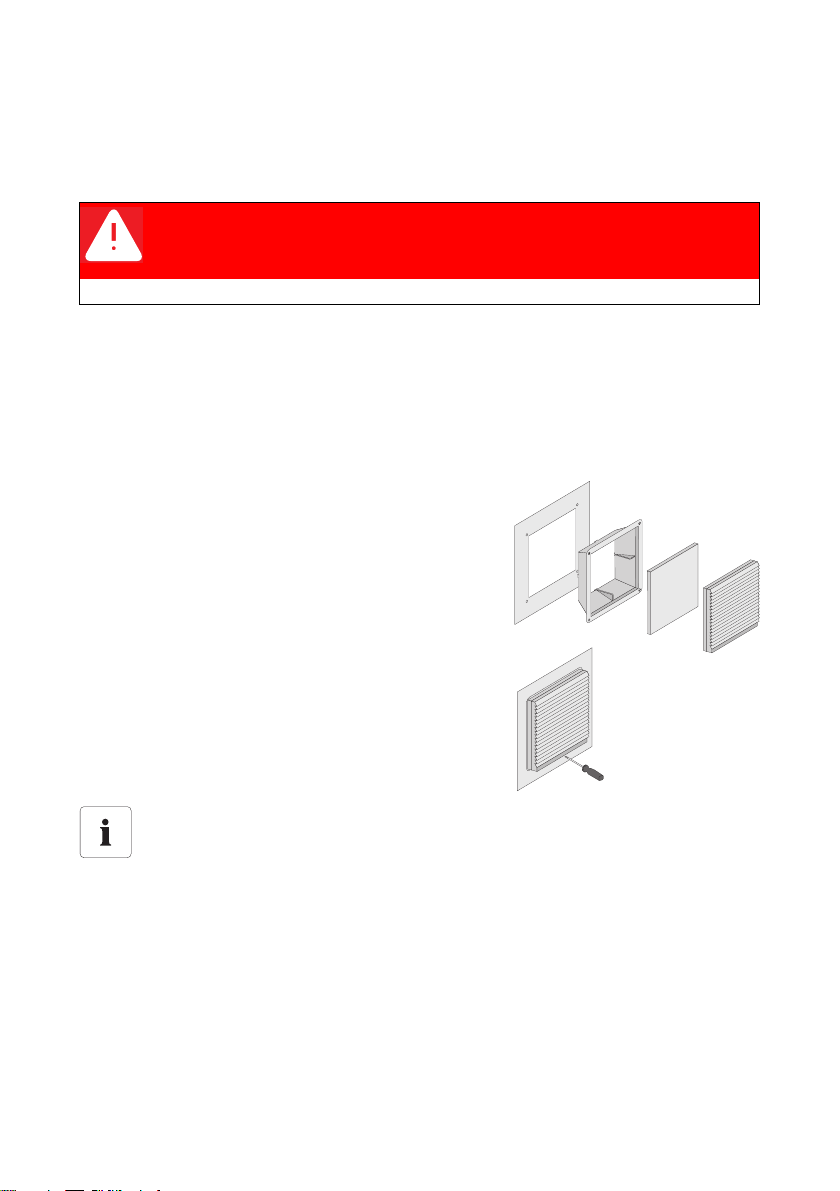
Disassembling and installing the ventilation grids with the appropriate filter pads
1. Slightly lift the top part of the ventilation grid by using
a screwdriver and pull the grid together with the top
part forward. The frame of the ventilation grids is
securely attached to the switch cabinet's door and
cannot be removed.
2. Remove the filter pads. The filter pad is in a cutout in
the top part of the ventilation grid.
3. If the filter pad needs to be replaced, you can order it
from SMA: Article number 65-102011.
4. Insert the filter pad. During mounting, the white side
must point outwards and the bluish side to the inside
of the switch cabinet.
Smaller filter pads
There is no separate article number for the small filter pads which are installed in the older
version of the Sunny Central 500; they have to be cut out from the large filter pads.
Maintenance Manual SCWAR-WEN094020 11
Maintaining the Sunny Central SMA Solar Technology AG
Cleaning the filter pads
• Clean with water (up to approx. 40 °C; you can also additionally use commercially available
mild detergent).
• Tap or vacuum the filter material, or carefully use pressurized air to remove the contamination.
• For dust containing grease, you should rinse with warm water and additionally use degreaser.
The air filter pad may not be cleaned with strong water jet or wrung out.
• As soon as the air filter pads are cleaned and dried, put them back into the frame.
Cleaning the ventilation grids
• The grids can be cleaned using a paintbrush, vacuum, or applying pressurized air.
Position of the ventilation grids
With the help of some example cabinets, the following section shows the exact position
and size of the individual ventilation grids.
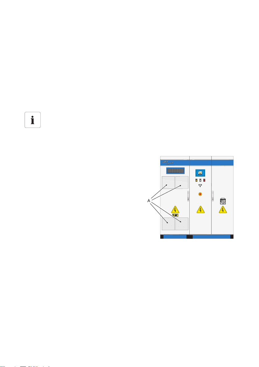
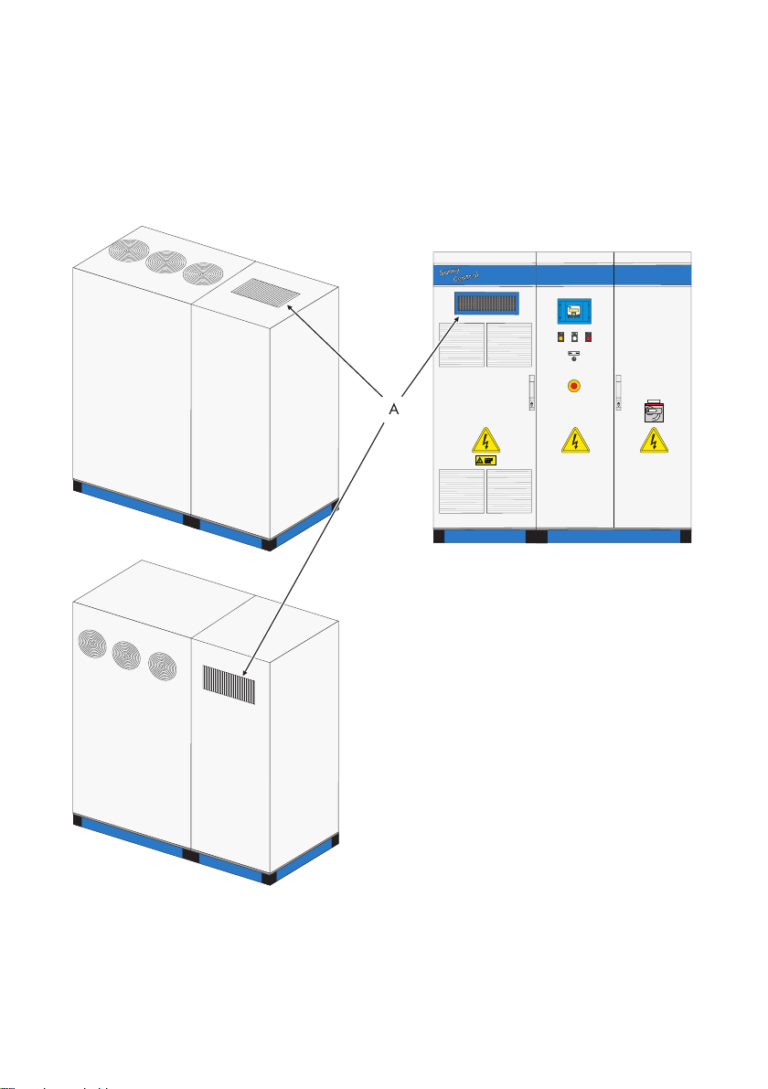
3.4.2 Sunny Central 100LV / SC 150 / SC 125LV / SC 200 / 200HE
The switch cabinets of type SC 100LV, SC 150,
SC 125 LV and SC 200 are mostly identical in
construction and equipped with four large air inlet filters
(A).
12 SCWAR-WEN094020 Maintenance Manual
SMA Solar Technology AG Maintaining the Sunny Central
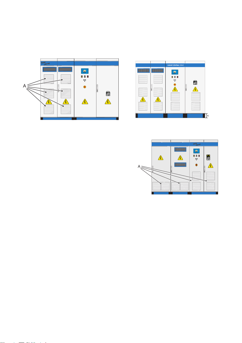
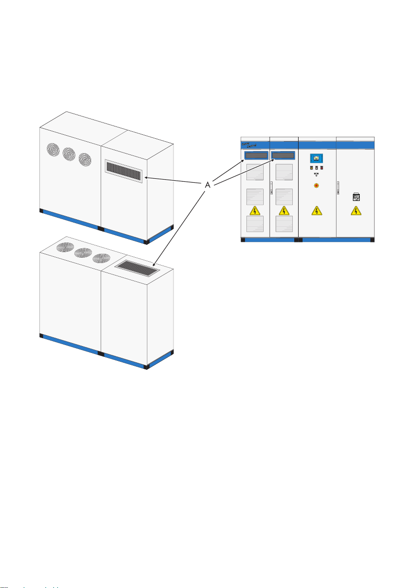
3.4.3 Sunny Central 250 / 250HE
The switch cabinet of the SC 250 is equipped with six large (A) air inlet filters. The switch cabinets of
the new series have four further air inlet filters in the AC cabinet.
3.4.4 Sunny Central 350 / SC 350HE
The switch cabinet of the SC 350 is equipped with eight
large (A) air inlet filters.
Maintenance Manual SCWAR-WEN094020 13
Maintaining the Sunny Central SMA Solar Technology AG
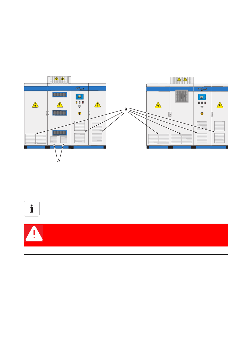
3.4.5 Sunny Central 500HE / 560HE / 400HE-11 / 500HE-11 / 630HE-11
Depending on the design, the switch cabinet of the SC 500HE is equipped with two small air inlet
filters (A) and six large air inlet filters (B) or only eight large air inlet filters (B). Only in this model, the
switch cabinet of the SC 560HE is equipped with eight large air inlet filters.
3.5 Cleaning the insect guard
Cleaning the insect guards at the air inlets and outlets
This section describes how to clean the insect guards at the air inlets and outlets.
Exchanging the protective grids
Exchanging the protective grids is only necessary in case of damage.
DANGER!
Death resulting from electric shock and burning upon touching the mediumvoltage grid's live components.
• Only work on the device when it is switched off and voltage-free.
Depending on the switch cabinet type and model, the insect guards must be cleaned in the roof and
plinth area, in the doors of the inverter cabinets and back sides of the doors. The air for cooling the
power units is drawn through and blown out through these insect guards.
The guards can be cleaned using a paintbrush, or handheld brush or by vacuuming, or applying
pressurized air.
Cleaning fine guards using pressurized air is prohibited. They are designed thinner and are used for
finger protection. Such protective grids are installed on the rear of the switch cabinets.
14 SCWAR-WEN094020 Maintenance Manual
SMA Solar Technology AG Maintaining the Sunny Central
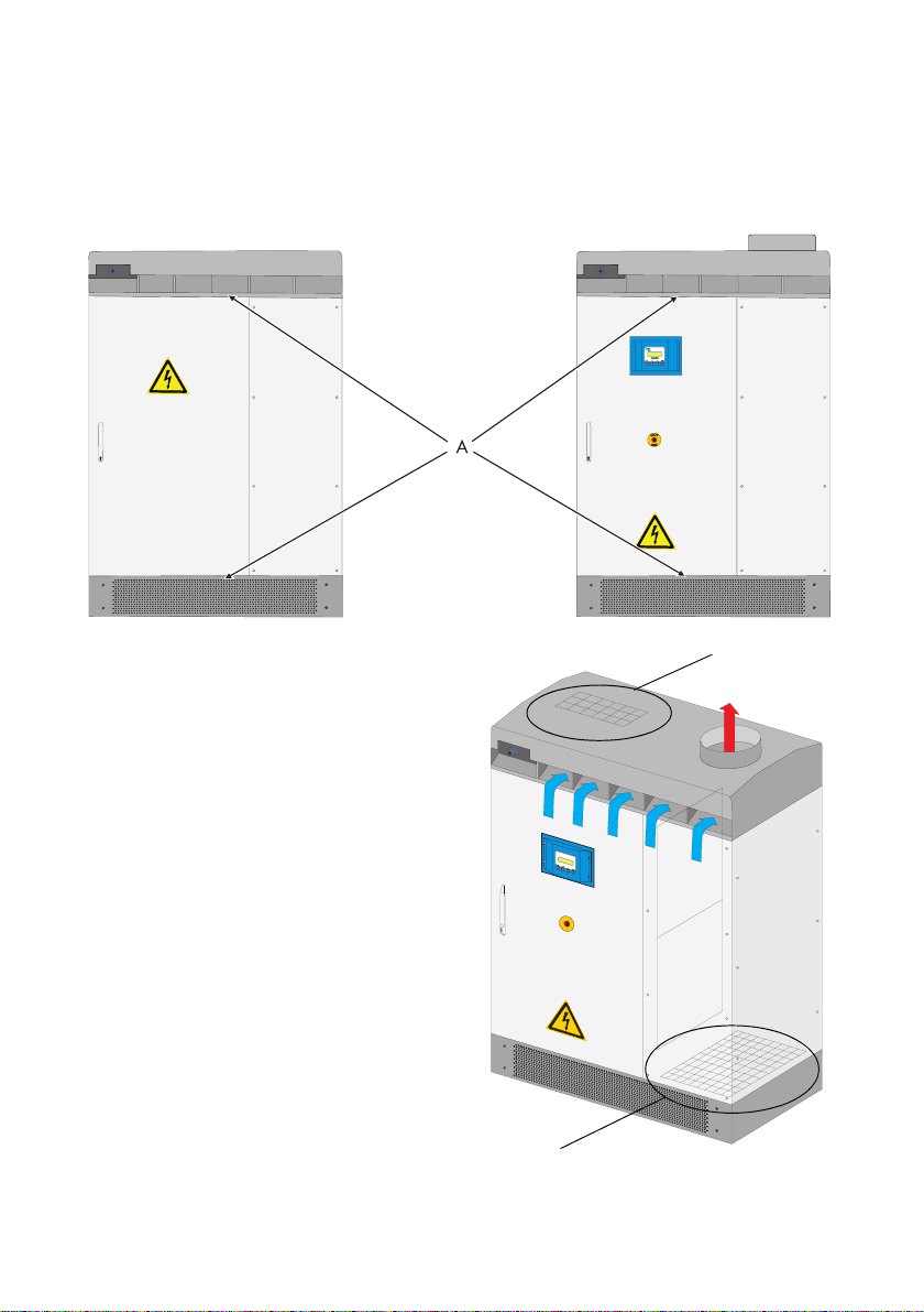
Front view
Rear view
Ventilation
Position of the protective grids
The following examples illustrate the exact position and size of the individual protective
grids.
3.5.1 Sunny Central 100 outdoor (older model)
The switch cabinet of the SC 100 is equipped with a protective grid in the plinth area. The cooling air
is drawn through the filter in the plinth and blown out through the guard plate on the back panel of
the inverter.
Maintenance Manual SCWAR-WEN094020 15
Maintaining the Sunny Central SMA Solar Technology AG
Protective grid
Protective grid
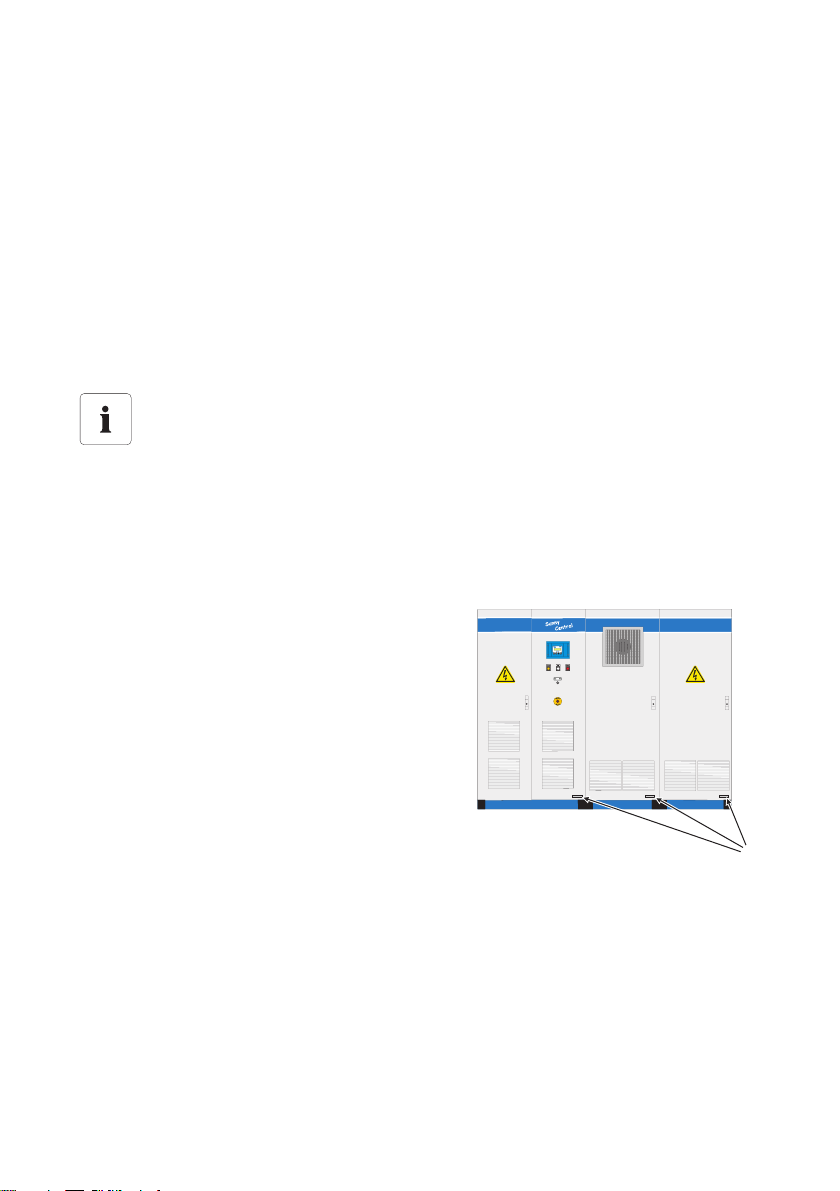
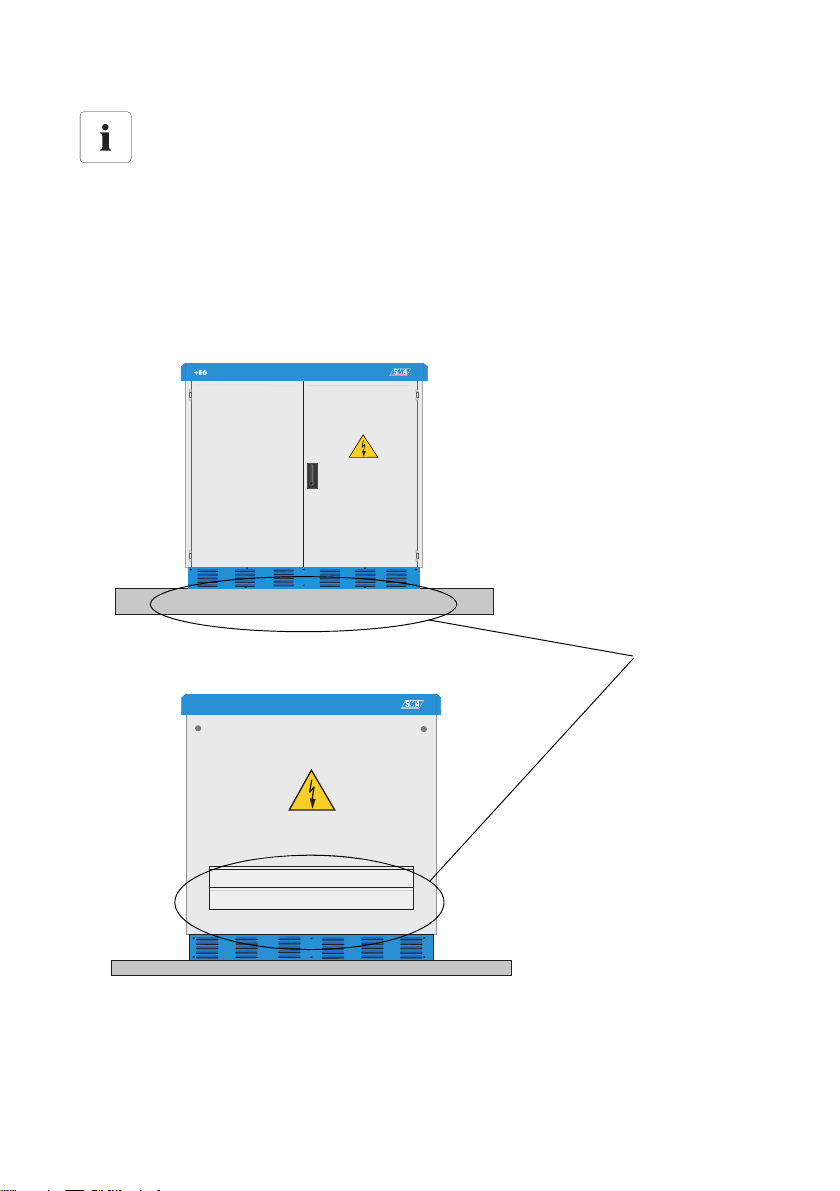
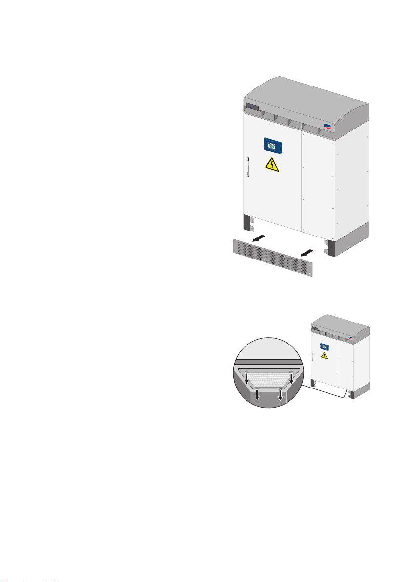
3.5.2 Sunny Central 100 indoor /outdoor (new model)
Both cabinets have large-meshed protective grids (A) in the roof and one in the plinth area.
View of the SC 100 ventilation
The air is drawn sucked-in trough the roof. In the
outdoor version, the air is emitted through the
plinth, in the indoor version through the roof. The
actual airflow is protected by the plinth panel as
well as by the roof and has a further air filter, in this
case a fine-meshed air filter. The indoor version
has no filter in the exhaust air area; it is not
included in the delivery. In this case also the base
is sealed with a plate.
Cleaning the filter of the supply air requires a prior
disassembly of the roof.
Cleaning the filter of the exhaust air requires a
prior disassembly of the plinth panel.
16 SCWAR-WEN094020 Maintenance Manual
SMA Solar Technology AG Maintaining the Sunny Central
S
U
N
N
Y
C
E
N
T
R
A
L
1
0
0
A
A
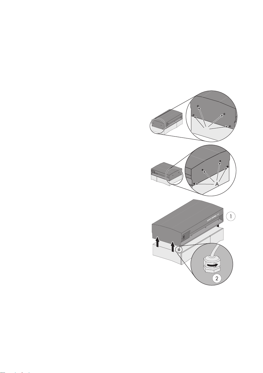
3.5.3 Removing the roof
The Sunny Central 100 indoor usually has an air duct through which the exhaust air is emitted to the
outside. The air duct must be disassembled in order to remove the roof.
Depending on the product version, the Sunny Central 100 is produced with different roofs. The
following describes how to disassemble the roof of both production versions.
Disassembling version 1
1. Loosen the screws at the left side in the roof of the
Sunny Central.
2. Loosen the screws at the right side in the roof of the
Sunny Central.
3. Lift the roof (1).
4. Remove the Start / Stop switch (2).
☑ The roof is removed.
Maintenance Manual SCWAR-WEN094020 17
Maintaining the Sunny Central SMA Solar Technology AG
SUNNY CENTRAL 100
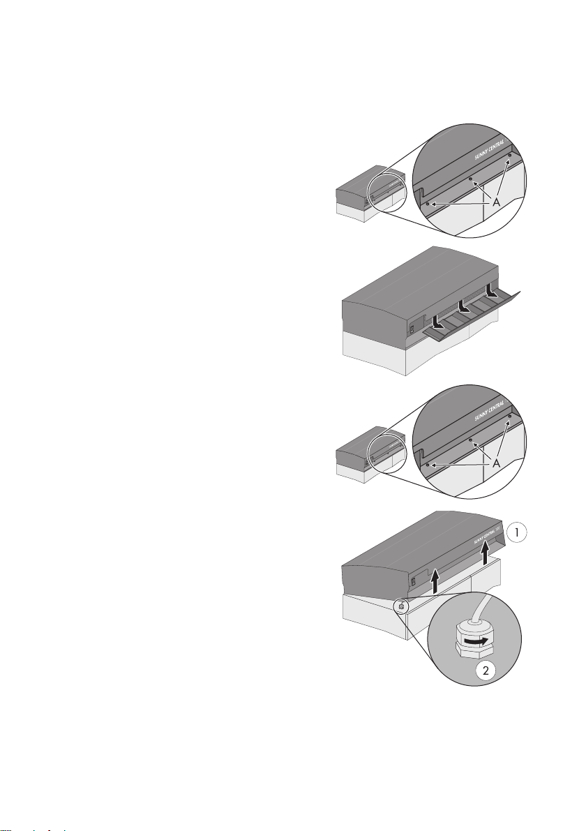
Disassembling version 2
1. Remove the Start / Stop switch.
2. Loosen the screws at the front filter in the roof of the
Sunny Central.
3. Loosen the screws at the back filter of the Sunny
Central.
4. Pull the front filter forward and remove it.
5. Pull the rear filter forward and remove it. Put the filters
aside.
6. Remove the screws (A) which hold the roof at the
Sunny Central. The screws are i n the pl ace where th e
front filter was attached before.
☑ Th e ro of can no w be til ted bac kwar ds ( 1) to cle an
the filter in the roof of the switch cabinet.
➤ I f th ere is n ot e nou gh s pac e to tilt the roo f backwa rds ,
remove it. To do so, loosen the cable gland (2) of the
switch.
7. Unhook the roof and remove it by pulling it upwards.
☑ The roof is removed.
18 SCWAR-WEN094020 Maintenance Manual
SMA Solar Technology AG Maintaining the Sunny Central
SMA
S
M
A
3.5.4 Removing the plinth panels
Depending on the production version, the plinth panel of
the Sunny Central 100 consists of one unit or two units.
Identical plinth panels are installed in both production
versions.
1. Loosen the screws on the edges of the plinth panel.
2. Remove the plinth panel by pulling it forward.
☑ The plinth panel is removed.
3.5.5 Removing the exhaust air filter in the base
1. Loosen the thumb nut at the filter in the base of the
switch cabinet.
2. Remove the filter.
☑ The filter can now be cleaned.
Maintenance Manual SCWAR-WEN094020 19
Maintaining the Sunny Central SMA Solar Technology AG
3.6 Sunny Central 100LV / SC 125LV / SC 150 /SC 200 / 200HE
The switch cabinets of type SC 100LV, SC 150, SC 125LV and SC 200 are mostly identical in
construction and equipped one protective grid (A) in the front. The exhaust air can either be
discharged to the top or the back. The inverter is therefore equipped with a protective grid (A) in the
roof or on the back side.
20 SCWAR-WEN094020 Maintenance Manual
SMA Solar Technology AG Maintaining the Sunny Central
3.7 Sunny Central 250 / 250HE
The switch cabinet of the SC 250 / 250HE has two protective grids (A) in the front of the inverter
cabinet. The exhaust air can either be discharged to the top or the back. Consequently, this device
has either a grid (A) on the back side or in the roof.
Maintenance Manual SCWAR-WEN094020 21
 Loading...