

SMA SUNNY CENTRAL User Manual
Central inverter
SUNNY CENTRAL
User Manual
SC-BEN092751 | TBE-SC-ALL | Version 5.1
EN


SMA Solar Technology AG Table of Contents
Table of Contents
1 Notes on this Manual. . . . . . . . . . . . . . . . . . . . . . . . . . . . . . 5
1.1 Symbols Used . . . . . . . . . . . . . . . . . . . . . . . . . . . . . . . . . . . . . . . 5
1.2 Target Group . . . . . . . . . . . . . . . . . . . . . . . . . . . . . . . . . . . . . . . 6
1.3 Applicability . . . . . . . . . . . . . . . . . . . . . . . . . . . . . . . . . . . . . . . . 6
1.4 Documentation . . . . . . . . . . . . . . . . . . . . . . . . . . . . . . . . . . . . . . 6
2 Safety Instructions . . . . . . . . . . . . . . . . . . . . . . . . . . . . . . . . 7
3 Description of the Sunny Central . . . . . . . . . . . . . . . . . . . . 9
3.1 Identifying the Sunny Central . . . . . . . . . . . . . . . . . . . . . . . . . . 10
3.2 The Sunny Central’s Control Elements . . . . . . . . . . . . . . . . . . . 11
3.2.1 Sunny Central Control. . . . . . . . . . . . . . . . . . . . . . . . . . . . . . . . . . . . . . . . . . 11
3.2.2 Light Indicators . . . . . . . . . . . . . . . . . . . . . . . . . . . . . . . . . . . . . . . . . . . . . . . 12
3.2.3 Start-up Key Switch . . . . . . . . . . . . . . . . . . . . . . . . . . . . . . . . . . . . . . . . . . . . 12
3.2.4 Emergency Shut-off . . . . . . . . . . . . . . . . . . . . . . . . . . . . . . . . . . . . . . . . . . . . 12
3.2.5 AC Switch . . . . . . . . . . . . . . . . . . . . . . . . . . . . . . . . . . . . . . . . . . . . . . . . . . . 13
3.3 Operating Modes. . . . . . . . . . . . . . . . . . . . . . . . . . . . . . . . . . . 14
3.3.1 Operating Modes of the Sunny Central . . . . . . . . . . . . . . . . . . . . . . . . . . . . 14
3.3.2 Operating Modes of Team Systems . . . . . . . . . . . . . . . . . . . . . . . . . . . . . . . 16
4 Sunny Central Control Operation. . . . . . . . . . . . . . . . . . . 18
4.1 Functions of the Control Buttons . . . . . . . . . . . . . . . . . . . . . . . . 19
4.2 Explanation of the Display Symbols . . . . . . . . . . . . . . . . . . . . . 20
4.3 Adjusting the Display Contrast . . . . . . . . . . . . . . . . . . . . . . . . . 20
4.4 Adjusting Parameters and Settings . . . . . . . . . . . . . . . . . . . . . . 20
5 Sunny Central Control Menu. . . . . . . . . . . . . . . . . . . . . . . 21
5.1 Overview of the Menu . . . . . . . . . . . . . . . . . . . . . . . . . . . . . . . 22
5.2 Setting the Language . . . . . . . . . . . . . . . . . . . . . . . . . . . . . . . . 23
5.3 Changing the Date and Time . . . . . . . . . . . . . . . . . . . . . . . . . . 24
User Manual SC-BEN092751 3

Table of Contents SMA Solar Technology AG
5.4 Entering the Password. . . . . . . . . . . . . . . . . . . . . . . . . . . . . . . . 26
6 Parameters . . . . . . . . . . . . . . . . . . . . . . . . . . . . . . . . . . . . . 28
6.1 Description of the Parameter Functions . . . . . . . . . . . . . . . . . . . 29
6.2 Default Parameter Settings . . . . . . . . . . . . . . . . . . . . . . . . . . . . 31
6.3 Adjusting Parameters . . . . . . . . . . . . . . . . . . . . . . . . . . . . . . . . 32
7 Communication. . . . . . . . . . . . . . . . . . . . . . . . . . . . . . . . . . 34
7.1 Remote-Info . . . . . . . . . . . . . . . . . . . . . . . . . . . . . . . . . . . . . . . . 34
7.2 Activating E-mail Reports. . . . . . . . . . . . . . . . . . . . . . . . . . . . . . 36
7.3 Entering or Changing E-Mail Addresses . . . . . . . . . . . . . . . . . . 36
7.4 Selecting the Report Types to Send . . . . . . . . . . . . . . . . . . . . . 37
7.5 Sending a Test Report. . . . . . . . . . . . . . . . . . . . . . . . . . . . . . . . 39
8 External Sensors. . . . . . . . . . . . . . . . . . . . . . . . . . . . . . . . . 40
8.1 Configuring the External Sensors . . . . . . . . . . . . . . . . . . . . . . . 40
8.2 Calculating Gain and Offset. . . . . . . . . . . . . . . . . . . . . . . . . . . 43
9 Failures and Warnings . . . . . . . . . . . . . . . . . . . . . . . . . . . 45
9.1 Fault Diagnosis . . . . . . . . . . . . . . . . . . . . . . . . . . . . . . . . . . . . . 45
9.1.1 Categories of Failures and Warnings . . . . . . . . . . . . . . . . . . . . . . . . . . . . . . 45
9.1.2 Types of Failures and Warnings . . . . . . . . . . . . . . . . . . . . . . . . . . . . . . . . . . 46
9.1.3 Warnings . . . . . . . . . . . . . . . . . . . . . . . . . . . . . . . . . . . . . . . . . . . . . . . . . . . 47
9.1.4 Failures . . . . . . . . . . . . . . . . . . . . . . . . . . . . . . . . . . . . . . . . . . . . . . . . . . . . . 51
9.2 Confirming Errors at the Sunny Central Control . . . . . . . . . . . . 58
10 Maintenance. . . . . . . . . . . . . . . . . . . . . . . . . . . . . . . . . . . . 60
11 Contact . . . . . . . . . . . . . . . . . . . . . . . . . . . . . . . . . . . . . . . . 63
4 SC-BEN092751 User Manual
SMA Solar Technology AG Notes on this Manual
1 Notes on this Manual
1.1 Symbols Used
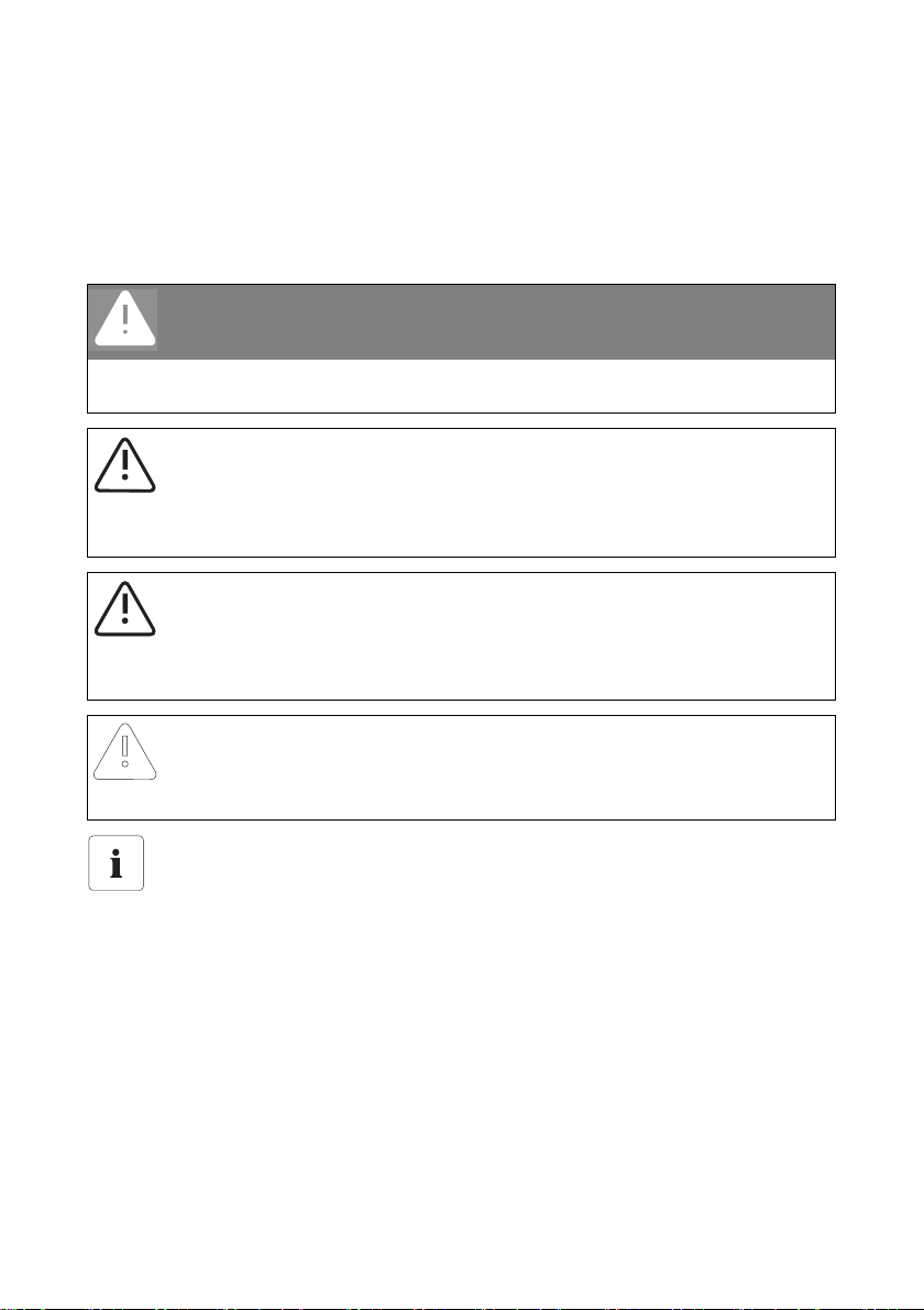
The following four types of warnings and general information appear in this document as described
below:
DANGER!
DANGER indicates a hazardous situation which, if not avoided, will result in death or
serious injury.
WARNING!
WARNING indicates a hazardous situation which, if not avoided, could result in death or
serious injury.
CAUTION!
CAUTION indicates a hazardous situation which, if not avoided, could result in minor or
moderate injury.
NOTICE!
NOTICE indicates a situation that can result in property damage if not avoided.
Information
Information provides tips that are valuable for the optimal installation and operation of
your product.
User Manual SC-BEN092751 5

Notes on this Manual SMA Solar Technology AG
1.2 Target Group
This documentation is intended for Sunny Central installers and operators. It includes a description of
how to operate the Sunny Central Control, maintenance of the Sunny Central, and troubleshooting
with the aid of the Sunny Central Control.
1.3 Applicability
This documentation describes how to operate the Sunny Central indoor and outdoor central inverters.
It applies for software versions 6.07 and 6.08.
1.4 Documentation
The following list shows the documents which you receive with your Sunny Central, and the
information which each respective document contains:
• Installation guide: setup and installation of the Sunny Central
• User manual: how to operate the Sunny Central and Sunny Central Control
• Wiring diagrams: the Sunny Central's wiring diagrams
• Technical data sheets: technical data pertaining to the Sunny Central
6 SC-BEN092751 User Manual
SMA Solar Technology AG Safety Instructions
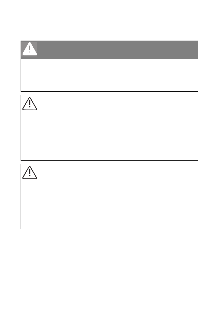
2 Safety Instructions
DANGER!
Risk of lethal electric shock!
Death resulting from burning and electric shock upon touching the medium-voltage grid's
live components.
• Do not touch the live components of the Sunny Central or medium-voltage grid.
• Observe all safety regulations which apply to activity that involves the mediumvoltage grid.
WARNING!
Risk of lethal electric shock!
High voltages are present in the device.
• All work on the Sunny Central must be carried out by a trained and qualified
electrician!
• Work on the Sunny Central is only to be performed as described in the following
sections!
• Observe all safety instructions listed!
• Follow all safety instructions included in the Sunny Central's installation guide!
WARNING!
Lethal danger caused by damage to the Sunny Central!
Damage to the Sunny Central, e.g. defective cables, or a damaged housing, can lead to
death by electric shock or fire!
• Only use the Sunny Central when it is safe to do so!
• Only use the Sunny Central if no damage is visibly evident!
• Visually check the Sunny Central for damage on a regular basis!
• Ensure that all exter nal safety features are freely accessible at all times, and t hat they
are regularly tested for correct functionality!
User Manual SC-BEN092751 7
Safety Instructions SMA Solar Technology AG
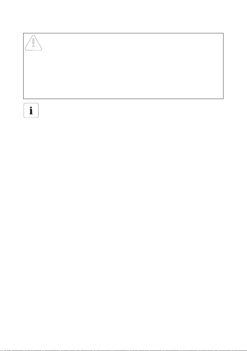
NOTICE!
Possible damage to the Sunny Central!
The Sunny Central can be damaged irreparably by electrostatic discharge at its
components.
• When working on the Sunny Central, and handling the module assemblies,
remember to observe all ESD safety regulations!
• Discharge any electrostatic charge by touching the grounded Su nny Central housing
• before handling electronic components!
Storage of handbooks
This user manual, the installation guide, the data sheets, the operating manuals of installed
components, and the wiring diagrams must be kept in the immediate vicinity of the Sunny
Central. They must be available to operators and maintenance staff at all times.
8 SC-BEN092751 User Manual
SMA Solar Technology AG Description of the Sunny Central
3 Description of the Sunny Central
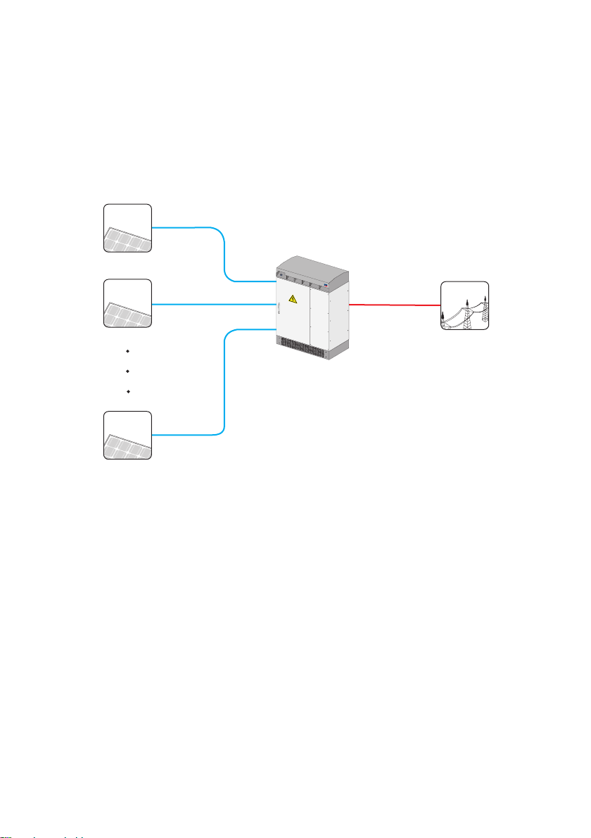
The Sunny Central is a solar inverter. It allows photovoltaic solar energy from solar modules to be
converted and fed into a low-voltage or medium-voltage grid.
Principle of a grid-connected solar power system with a Sunny Central
Solar modules
Sunny Central
Public grid
S
M
A
Sunny Central
The standard Sunny Central is equipped with a low-voltage transformer, and feeds into the lowvoltage grid.
Sunny Central HE
The Sunny Central HE is a high efficiency photovoltaic inverter. It does not have its own low-voltage
transformer. The Sunny Central HE requires an adapted external medium-voltage transformer via
which it can feed into the grid.
Sunny Central MV
The MV stations are medium-voltage stations. In an MV station, two Sunny Central HE devices feed
into a shared medium-voltage transformer. The Sunny Central MV feeds into the medium-voltage grid.
User Manual SC-BEN092751 9
Description of the Sunny Central SMA Solar Technology AG
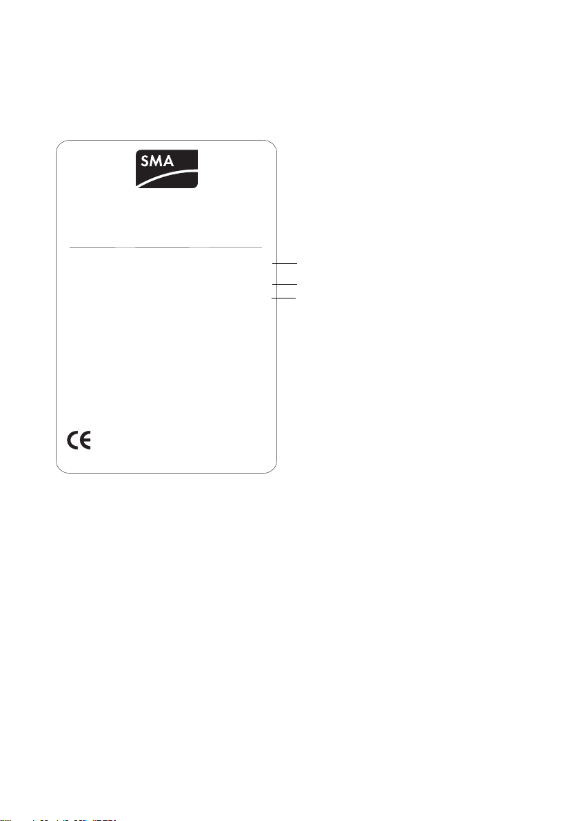
3.1 Identifying the Sunny Central
You can identify the Sunny Central using the name plate (see figure below). The name plate is located
on the inside of the Sunny Central's door.
SMA Technologie AG
Hannoversche Str. 1-5, 34266 Niestetal, Germany
Tel: +49 561 9522-0 Fax: +49 561 9522-100
Typ: SC-100: 010.322.03
Version:
Serial No.:
Year of manufacture:
AC-Voltage/-current:
Max. DC-Voltage/current:
EVR (Option):
Auxiliary Voltage:
Testing Voltage:
Weight:
made in germany www.sma.de
400V,50Hz/261A
1000V/354A
AC230V, 50Hz/DC24V
1,7kV/2,6 (2,8)kV DC
100
02/2007
900V/354A
1450kg
Es
A
B
C
A The Sunny Central's type name with option code (optional).
B The version of the Sunny Central; "s" means special version.
C Serial number of the Sunny Central.
10 SC-BEN092751 User Manual
SMA Solar Technology AG Description of the Sunny Central
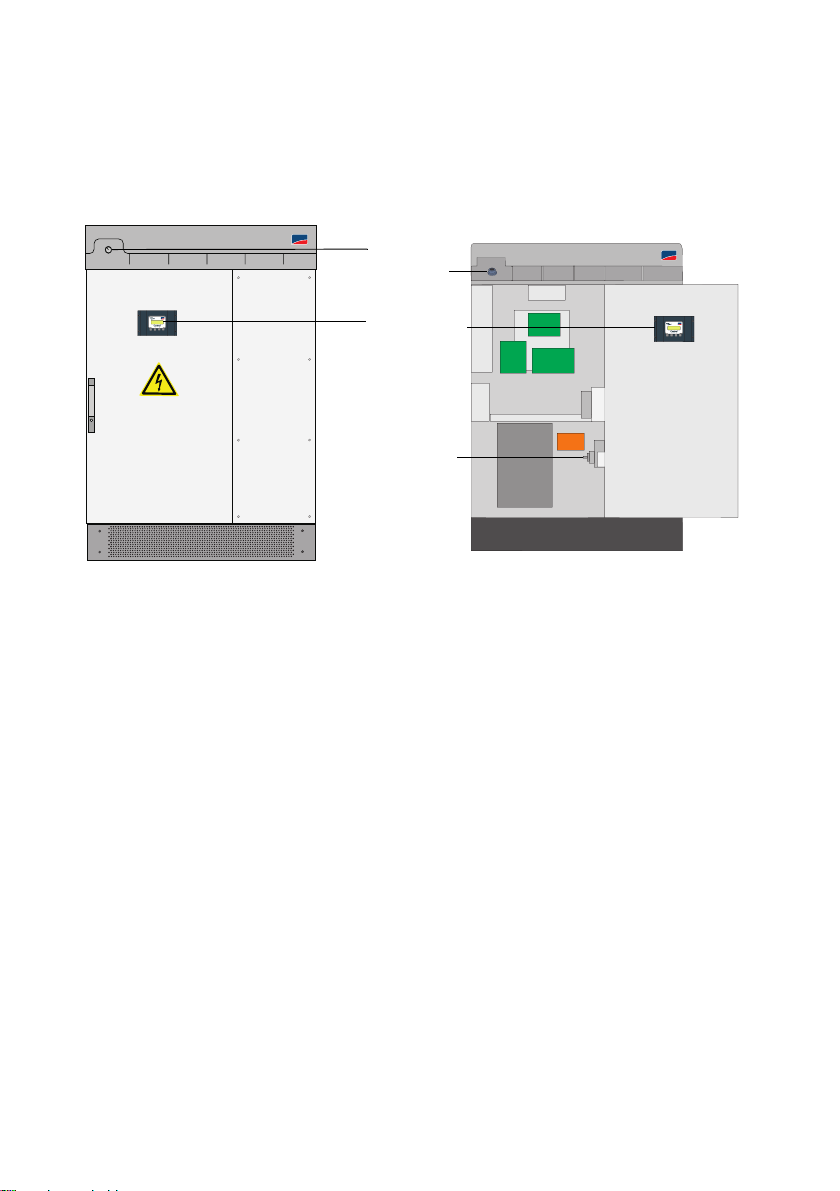
3.2 The Sunny Central’s Control Elements
The illustrations below represent two different Sunny Centrals, and allow you to identify the
approximate locations of the Sunny Centrals' control elements.
Sunny Central 100
Sunny Central 100
SMA
B
B
Sunny Central 100 open
SMA
SMA
A
A
SMA
C
A Sunny Central Control
B Start-up key switch
CAC switch
3.2.1 Sunny Central Control
Sunny Central settings can be adjusted directly at the device by means of the Sunny Central Control.
The functions that the Sunny Central Control performs can be grouped into the following areas:
• Controlling inverter operation
• Displaying present measuring data
• Adjusting Sunny Central parameters
• Maximum power point tracking
• Recording and archiving measurement data
• Remote access capability with NET Piggy-Back
• Connection of external sensors
User Manual SC-BEN092751 11
Description of the Sunny Central SMA Solar Technology AG
3.2.2 Light Indicators
Three light indicators are situated on the front of the Sunny Central. If an error occurs, the type of
disturbance is shown by these light indicators.
• Yellow: The Sunny Central is in "Alert" mode. The Sunny Central does not switch itself off.
Once the error is no longer present, the error message is reset automatically. Check
the system.
• White: The Sunny Centrals are operating in Team mode. The Team contactor is activated.
• Red: The Sunny Central is in "Failure" mode. If the Sunny Central has detected a failure,
it shuts down. Once the fault has been removed and confirmed, it resumes
operation. For more information, see section 9.1.2 "Types of Failures and
Warnings" (page46).
3.2.3 Start-up Key Switch
The start-up key switch activates or deactivates the Sunny Central. When this switch is turned to the
"Start" position, the Sunny Central changes from "Stop" mode to "Wait" mode. If there is sufficient
radiation, the Sunny Central changes to the "Startup" mode, and subsequently begins grid feeding. If
the radiation, and thus the input voltage, is too low, the Sunny Central remains in "Wait" mode.
If the start-up key switch is turned to the "Stop" position, th e DC switch is deactivated automatically by
a motor drive.
3.2.4 Emergency Shut-off
NOTICE!
Improper use of the emergency shut-off switch causes damage to the Sunny
Central!
The Sunny Central's components are subjected to considerable stress if the emergency shutoff switch is used under load. This can irreparably damage individual components.
• Only use the emergency shut-off switch in an emergency.
• To switch off the Sunny Central, use the start-up key switch.
The emergency shut-off switch immediately disconnects the Sunny Central from the grid, and from the
solar generator, placing the Sunny Central in a safe condition.
When the emergency shut-off switch is pressed, it locks in the "Off" position. The emergency shut-off
sw itc h ca n on ly b e un locked usi ng i ts k ey. It i s al so n ece ssary to reset the emergency shut-off operation
with the Sunny Central Control or with Sunny Data Control.
The Sunny Central 100 indoor and the Sunny Central 100 outdoor have no emergency shut-off
switch. You have the option of installing an external emergency shut-off switch at the Sunny Central.
You can also install an external emergency shut-off switch at the other Sunny Centrals, or deactivate
several Sunny Centrals with a shared emergency shut-off switch.
12 SC-BEN092751 User Manual

SMA Solar Technology AG Description of the Sunny Central
3.2.5 AC Switch
NOTICE!
Improper use of the AC switch may cause damage to the Sunny Central!
The Sunny Central's components are subjected to considerable stress if the AC switch is
used under load. This can irreparably damage individual components.
• Only use the AC switc h if the Sunny Cent ral ha s been set to "Stop" by turning the startup key switch.
Upon use of the AC switch, the Sunny Central is disconnected from the grid on the AC side.
User Manual SC-BEN092751 13
Description of the Sunny Central SMA Solar Technology AG
3.3 Operating Modes
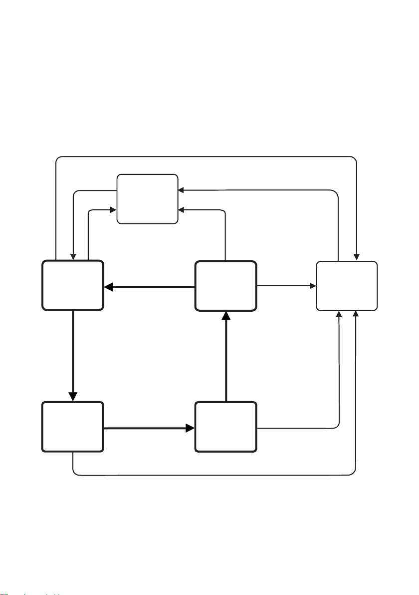
3.3.1 Operating Modes of the Sunny Central
When activated, the Sunny Central passes through different modes as pictured below. When
deactivated, the Sunny Central resides in the operating mode "Stop". If the key switch is turned, the
Sunny Central changes to the "Wait" mode
.
Failure
"Start" switch
Wait
Vpv > UpvStart
und T > Tstart
Startup
"Stop"
Start-up finished
Stop
"Stop"
Shutdown
MPP load
operation
No failure
Failure
Failure
Ppv < PpvStop
and T > Tstop
or
switch "Stop"
Failure
Failure
14 SC-BEN092751 User Manual
SMA Solar Technology AG Description of the Sunny Central
Stop
The Sunny Central is deactivated. The Sunny Central remains in this mode until the start-up key switch
is turned to the start position.
Wait
If the input voltage is below the defined start voltage "UpvStart", the Sunny Central resides in "Wait"
mode. The value of the UpvStart setting is shown in the Sunny Central Control's display.
Startup
If the input voltage is above the start voltage "UpvStart", the Sunny Central waits until t he tim e defined
by the parameter "Tstart" has passed. If the input voltage has not fallen below the start voltage
"UpvStart" during this period, the Sunny Central starts up.
The AC contactor is closed and the Sunny Central is isolated. Once the Sunny Central is ready for
operation, it begins grid feeding.
Start Voltage UpvStart
The start voltage UpvStart must be adjusted for the solar generator which is connected to
the Sunny Central.
MPP Load Operation
After successful activation, the Sunny Central seeks the solar generator's maximum power point
(MPP), and begins feeding into the grid.
Shutdown
The Sunny Central shuts down if:
• the power measured during the interval "Tstop" is less than "PpvStop",
• a failure occurs which requires a shutdown of the Sunny Central, or
• the start-up key switch is set to "Stop".
Failures
If a failure occurs during operation, the Sunny Central shuts down and the failure is shown as a
disturbance in the Sunny Central Control's display. Refer to section 9 "Failures and Warnings"
(page45) for a list of disturbances.
User Manual SC-BEN092751 15

Description of the Sunny Central SMA Solar Technology AG
3.3.2 Operating Modes of Team Systems
In addition to the normal operating modes, Sunny Centrals which are configured as a Team system
also have Team operating modes.
Stop
If one of the two Sunny Centrals is deactivated, the second Sunny Central is operated individually
without Team. If only the Team leader is operating, it is in the "Startup" mode. If only the Team member
is operating, it resides in the "String Operation" mode.
Linking (Mornings)
The Team contactor is disconnected. If the input voltage (Vpv) of both Sunny Centrals is greater than
the PV start voltage (UpvStart) - 50 V, the Team contactor closes itself. The Team leader begins to
operate as soon as the start conditions are fulfilled. The Team leader goes into the "Team leader"
mode and feeds the power into the grid. The Team member changes to the "PV linked" mode. The
Team leader and the Team member operate as a Team.
Disconnecting
Th e Te am m emb er i s in "Te am mo de" . Th e Te am l ead er i s in "Te am le ade r" m ode . Bo th S unn y Ce ntra ls
are feeding into the grid.
If the Team leader's output exceeds the value of "P-NextTeam" (default setting: 80 %), the DC
contactor is switched off. Both Sunny Centrals then operate individually, and feed into the grid.
Linking (Evenings)
If the Team leader's AC output falls below the value of "P-PrevTeam" (default setting: 20 %), the Team
contactor is switched on. The Team leader feeds the entire system power into the grid, and is in the
"Team leader" mode. The Team member is in "PV linked" mode.
Night Operation
If the Team leader's open circuit voltage is below UpvMin - 100 V for 30 minutes, the Team contactor
is disconnected. The Team leader changes to "Startup" mode. The Team member changes to "Team
mode".
16 SC-BEN092751 User Manual

SMA Solar Technology AG Description of the Sunny Central
Failures
If, when in Team mode, a failure occurs, the Team mode is immediately interrupted, and the Team
contactor is disconnected. The Sunny Centrals continue to operate individually until the failure is
rectified.
If a failure is present for more than 60 minutes, Team mode can be resumed. For Team mode to be
possible while a failure is present at a Sunny Central, the following conditions must be fulfilled:
• The communication between the two Sunny Centrals must be functioning.
• The DC contactor must be functioning.
• The start-up key switch must be set to the "Start" position.
• None of the following failures must be present:
– Failure 201: Ground Fault 2 or plant temp. too high
– Failure 206: Emergency shutdown activated
If these conditions are fulfilled, the Sunny Central at which no failure is present takes over the output
of both solar generators.
User Manual SC-BEN092751 17
Sunny Central Control Operation SMA Solar Technology AG
4 Sunny Central Control Operation
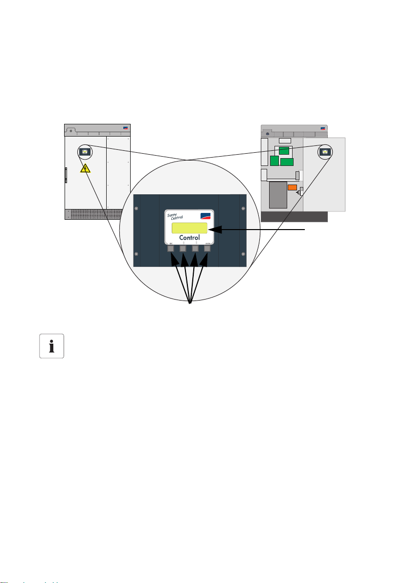
Th e co ntr ol p ane l Su nny C ent ral Con tro l is mou nte d in or on the Sunn y Ce ntr al a t eye lev el. The Sun ny
Central Control is operated by means of the four buttons below the four-line display.
Sunny Central 100
SMA
SMA
SMA
SMA
Sunny Central Control panel
SMA
4-line display
Control buttons
Operating the Sunny Central Control with SC 100 Indoor and SC 100 Outdoor
Inverters
With the Sunny Central SC 100 indoor and SC 100 outdoor inverters, the Sunny Central
Co ntr ol i s si tua ted ins ide the inver ter . Th e Su nny Cen tra l Co ntrol may only be used in "Stop"
mode with these devices.
Open the Sunny Central as described in the installation guide.
18 SC-BEN092751 User Manual
SMA Solar Technology AG Sunny Central Control Operation
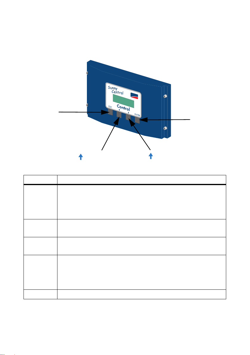
4.1 Functions of the Control Buttons
The four control buttons are situated below the Sunny Central Control's display.
SMA
ESC
ENTER
Upward arrow
Downward arrow
The control buttons have several functions. In the following table, the buttons' functions are explained.
Button Meaning and function
[ESC] • cancels / ends the present function
• answers questions with "No"
• returns to the previous menu
• changes from the online info display to the main menu
[ ↑ ] • moves up to the previous line
• increases the present value
[ ↓ ] • moves down to the next line
• decreases the present value
[ENTER] • selects a function from the menu
• selects a value
•confirms changes
• answers questions with "Yes"
[ ↑ ] + [ ↓ ] • returns to the online info display
User Manual SC-BEN092751 19
Sunny Central Control Operation SMA Solar Technology AG
4.2 Explanation of the Display Symbols
The Su nny Ce ntral Control display h as fou r lines. It uses va rio us display symbols, which are explained
in the following table.
Symbol Meaning
↑ There are more display lines above.
↓ There are more display lines below.
↕ There are more display lines above and below.
→ Appears at the left of the presently selected line. Press [ ↑ ] or [ ↓ ] to move to
another line.
→
(glows)
→
(flashes)
¿
Appears to the left of a value which can be changed.
If, for example, a parameter has been changed, the arrow flashes at the left of the
active line.
The Sunny Central Control is loading the next menu, or saving data.
4.3 Adjusting the Display Contrast
Yo u ca n ad jus t the dis pla y co ntr ast in a ny m enu . Yo u mus t pr ess a combination of two buttons in order
to increase or decrease the contrast.
Buttons Function
[ESC] + [ ↑ ] increases the display contrast
[ESC] + [ ↓ ] decreases the display contrast
4.4 Adjusting Parameters and Settings
You can adjust the Sunny Central's parameters and settings in edit mode. Only parameters which
have a solid arrow to their left ( → ) can be adjusted.
Press [ENTER] to access the parameter's edit mode. The parameter's value begins to flash. You can
adjust the value with the two arrow buttons. Confirm the change with [ENTER], or cancel with [ESC].
If no button is pressed for 60 seconds, the change is automatically cancelled.
Password for Adjusting Parameters
Parameters can only be adjusted after an installer password has been entered (see section
5.4 "Entering the Password" (page26)).
20 SC-BEN092751 User Manual
SMA Solar Technology AG Sunny Central Control Menu
5 Sunny Central Control Menu
The Sunny Central Control initializes upon activation of the Sunny Central. The initialization includes
a sequence of three displays. Once the Sunny Central Control has initialized, it changes to the online
info display. In the online info display, your Sunny Central's measured values and spot values are
displayed.
Status MPP
Pac 85.7kW
E_Today 357.5kWh
E_Total 2512.3kWh
[ ↑ ], [ ↓ ] or [ENTER]
Status MPP
Ppv 89.27kW
Vpv 557V
Ipv 160.26A
[ ↑ ], [ ↓ ] or [ENTER]
Status MPP
fac 50.04Hz
Vac 230.51V
Iac 124.07A
You can switch between the three online info displays with the buttons [ ↑ ], [ ↓ ] or [ENTER]. If a
warning or failure is reported, the display will alternate between the present online info display and
the error with the highest priority.
User Manual SC-BEN092751 21
 Loading...