

SMA SUNNY BOY STORAGE 3.7, SUNNY BOY STORAGE 5.0, SUNNY BOY STORAGE 6.0 Operating Manual
Operating manual
SUNNY BOY STORAGE 3.7 / 5.0 / 6.0
SBSxx-10-BE-en-11 | Version 1.1ENGLISH

Legal Provisions
SMA Solar Technology AG
Legal Provisions
The information contained in these documents is the property of SMA Solar Technology AG. No
part of this document may be reproduced, stored in a retrieval system, or transmitted, in any form or
by any means, be it electronic, mechanical, photographic, magnetic or otherwise, without the prior
written permission of SMA Solar Technology AG. Internal reproduction used solely for the purpose
of product evaluation or other proper use is allowed and does not require prior approval.
SMA Solar Technology AG makes no representations or warranties, express or implied, with
respect to this documentation or any of the equipment and/or software it may describe, including
(with no limitation) any implied warranties of utility, merchantability, or fitness for any particular
purpose. All such representations or warranties are expressly disclaimed. Neither SMA Solar
Technology AG nor its distributors or dealers shall be liable for any indirect, incidental, or
consequential damages under any circumstances.
The exclusion of implied warranties may not apply in all cases under some statutes, and thus the
above exclusion may not apply.
Specifications are subject to change without notice. Every attempt has been made to make this
document complete, accurate and up-to-date. Readers are cautioned, however, that product
improvements and field usage experience may cause SMA Solar Technology AG to make changes
to these specifications without advance notice, or per contract provisions in those cases where a
supply agreement requires advance notice. SMA Solar Technology AG shall not be responsible for
any damages, including indirect, incidental or consequential damages, caused by reliance on the
material presented, including, but not limited to, omissions, typographical errors, arithmetical errors
or listing errors in the content material.
SMA Warranty
You can download the current warranty conditions from the Internet at www.SMA-Solar.com.
Software licenses
The licenses for the used software modules can be called up on the user interface of the product.
Trademarks
All trademarks are recognized, even if not explicitly identified as such. Missing designations do not
mean that a product or brand is not a registered trademark.
SMA Solar Technology AG
Sonnenallee 1
34266 Niestetal
Germany
Tel. +49 561 9522-0
Fax +49 561 9522-100
www.SMA.de
Email: info@SMA.de
Status: 4/8/2019
Copyright © 2019 SMA Solar Technology AG. All rights reserved.
Operating manualSBSxx-10-BE-en-112

SMA Solar Technology AG
Table of Contents
Table of Contents
1 Information on this Document................................................. 6
1.1 Validity........................................................................................................................ 6
1.2 Target Group.............................................................................................................. 6
1.3 Content and Structure of this Document ................................................................... 6
1.4 Levels of Warning Messages.................................................................................... 6
1.5 Symbols in the Document .......................................................................................... 7
1.6 Typographies in the Document.................................................................................. 7
1.7 Designation in the document..................................................................................... 7
1.8 Additional Information............................................................................................... 8
2 Safety ........................................................................................ 9
2.1 Intended Use .............................................................................................................. 9
2.2 IMPORTANT SAFETY INSTRUCTIONS.................................................................... 10
3 Scope of Delivery ..................................................................... 14
4 Product Overview .................................................................... 16
4.1 Product Description.................................................................................................... 16
4.2 Symbols on the Product ............................................................................................. 18
4.3 Interfaces and Functions ............................................................................................ 19
4.4 LED Signals................................................................................................................. 25
4.5 System Structure......................................................................................................... 27
4.6 "Battery Management" .............................................................................................. 29
4.6.1 Battery Use by Systems for Increased Self-Consumption..................... 29
4.6.2 Battery Use by Battery-Backup Systems with Increased Self-
Consumption........................................................................................... 30
5 Mounting................................................................................... 32
5.1 Requirements for Mounting ....................................................................................... 32
5.2 Mounting the Inverter................................................................................................. 34
6 Electrical Connection ................................................................ 37
6.1 Overview of the Connection Area............................................................................ 37
6.1.1 View from Below..................................................................................... 37
6.1.2 Interior View............................................................................................ 38
6.2 AC Connection........................................................................................................... 39
6.2.1 Requirements for the AC Connection.................................................... 39
6.2.2 Connecting the Inverter to the Utility Grid ............................................ 41
6.2.3 Connecting Additional Grounding........................................................ 43
6.3 Connecting the Network Cables............................................................................... 44
Operating manual SBSxx-10-BE-en-11 3

Table of Contents
6.4 Connecting the energy meter.................................................................................... 45
6.5 Connecting the Data Cable of the Battery and Communication Cable of the
Automatic Transfer Switch ......................................................................................... 47
6.6 Connecting the Switch and Outlet for Secure Power Supply Operation ............... 49
6.7 Connecting Switch for black start (in battery-backup systems)............................... 53
6.8 DC Connection........................................................................................................... 54
6.8.1 Possible Connection ............................................................................... 54
6.8.1.1 Connection of batteries with a charging/discharging
current limit of 10 A............................................................ 54
6.8.1.2 Connection of two batteries with different charging/
discharging currents............................................................ 55
6.8.1.3 Connection of one battery with a charging/discharging
current limit of 20 A............................................................ 56
6.8.1.4 Connection of a battery with a charging/discharging
current limit of 30 A............................................................ 56
6.8.2 Requirements for the DC Connection.................................................... 57
6.8.3 Connecting the power cable of the battery.......................................... 57
SMA Solar Technology AG
7 Commissioning ......................................................................... 59
7.1 Commissioning Procedure ......................................................................................... 59
7.2 Commissioning the Inverter........................................................................................ 59
7.3 Selecting a configuration option............................................................................... 61
8 Operation ................................................................................. 64
8.1 Establishing a connection to the user interface ........................................................ 64
8.1.1 Establishing a Direct Connection via Ethernet ...................................... 64
8.1.2 Establishing a direct connection via WLAN ......................................... 64
8.1.3 Establishing a Connection via Ethernet in the local network ............... 66
8.1.4 Establishing a Connection via WLAN in the Local Network ............... 67
8.2 Logging In and Out of the User Interface................................................................. 68
8.3 Start Page Design of the User Interface.................................................................... 69
8.4 Displaying and Downloading the Stored Data........................................................ 71
8.5 Starting the Installation Assistant............................................................................... 72
8.6 Secure Power Supply Operation .............................................................................. 73
8.6.1 Activating Secure Power Supply Operation......................................... 74
8.6.2 Deactivating Secure Power Supply Operation..................................... 74
8.7 Checking or Disabling Battery-Backup Operation................................................... 74
8.8 Activate WPS Function............................................................................................... 75
8.9 Switching WLAN On and Off................................................................................... 76
8.10 Changing the Password............................................................................................. 76
8.11 Changing Operating Parameters.............................................................................. 77
8.12 Configuring the Country Data Set............................................................................. 78
Operating manualSBSxx-10-BE-en-114

SMA Solar Technology AG
8.13 Configuring Feed-In Management............................................................................ 78
8.14 Configuring Battery and Automatic Transfer Switching Device.............................. 79
8.15 Disabling Battery Charging by PV System in Battery-Backup Operation Mode ... 80
8.16 Configuring the Modbus Function............................................................................. 80
8.17 Activating the Receipt of Control Signals (Only for Italy)........................................ 81
8.18 Deactivating Grounding Conductor Monitoring...................................................... 81
8.19 Configuring the Energy Meter................................................................................... 82
8.20 Saving the Configuration in a File............................................................................. 82
8.21 Adopting a Configuration from a File....................................................................... 83
8.22 Updating the Firmware.............................................................................................. 83
Table of Contents
9 Disconnecting the Inverter from Voltage Sources ................. 86
10 Cleaning the Inverter ............................................................... 87
11 Troubleshooting........................................................................ 88
11.1 Forgotten Password.................................................................................................... 88
11.2 Event Messages ......................................................................................................... 89
12 Decommissioning the Inverter.................................................128
13 Procedure for Receiving a Replacement Device....................131
14 Technical Data.......................................................................... 133
15 Contact ...................................................................................... 138
16 EU Declaration of Conformity ................................................. 141
Operating manual SBSxx-10-BE-en-11 5

1 Information on this Document
SMA Solar Technology AG
1 Information on this Document
1.1 Validity
This document is valid for:
• SBS3.7-10 (SunnyBoyStorage 3.7) from firmware version 1.50.10.R.
• SBS5.0-10 (SunnyBoyStorage 5.0) from firmware version 1.50.10.R.
• SBS6.0-10 (SunnyBoyStorage 6.0) from firmware version 1.50.10.R.
1.2 Target Group
This document is intended for qualified persons and end users. Only qualified persons are allowed
to perform the activities marked in this document with a warning symbol and the caption
"Qualifiedperson". Tasks that do not require any particular qualification are not marked and can
also be performed by end users. Qualified persons must have the following skills:
• Knowledge of how batteries work and are operated
• Training in how to deal with the dangers and risks associated with installing, repairing and
using electrical devices, batteries and installations
• Training in the installation and commissioning of electrical devices and installations
• Knowledge of all applicable laws, standards and directives
• Knowledge of and compliance with this document and all safety information
• Knowledge of and compliance with the documents of the battery manufacturer with all safety
information
1.3 Content and Structure of this Document
This document describes the mounting, installation, commissioning, configuration, operation,
troubleshooting and decommissioning of the product as well as the operation of the product user
interface.
You will find the latest version of this document and further information on the product in PDF format
and as eManual at www.SMA-Solar.com. You can also call up the eManual via the user interface
of the product.
Illustrations in this document are reduced to the essential information and may deviate from the real
product.
1.4 Levels of Warning Messages
The following levels of warning messages may occur when handling the product.
DANGER
Indicates a hazardous situation which, if not avoided, will result in death or serious injury.
WARNING
Indicates a hazardous situation which, if not avoided, could result in death or serious injury.
Operating manualSBSxx-10-BE-en-116
SMA Solar Technology AG
☐
☑
✖
1 Information on this Document
CAUTION
Indicates a hazardous situation which, if not avoided, could result in minor or moderate injury.
NOTICE
Indicates a situation which, if not avoided, can result in property damage.
1.5 Symbols in the Document
Symbol Explanation
Information that is important for a specific topic or goal, but is not safety-relevant
Indicates a requirement for meeting a specific goal
Desired result
A problem that might occur
Example
Sections describing activities to be performed by qualified persons only
1.6 Typographies in the Document
Typography Use Example
bold
>
[Button]
[Key]
• Messages
• Terminals
• Elements on a user interface
• Elements to be selected
• Elements to be entered
• Connects several elements to be
selected
• Button or key to be selected or
pressed
• Connect the insulated
conductors to the terminals
X703:1 to X703:6.
• Enter 10 in the field
Minutes.
• Select Settings > Date.
• Select [Enter].
1.7 Designation in the document
Complete designation Designation in this document
SMA Solar Technology AG SMA
SunnyBoyStorage Inverter, product
Operating manual SBSxx-10-BE-en-11 7

1 Information on this Document
SMA Solar Technology AG
1.8 Additional Information
For more information, please go to www.SMA-Solar.com.
Title and information content Type of information
"Approved batteries and battery communication connection"
Overview of approved batteries
"Application for SMAGridGuard Code" Form
"SMASmartHome"
The System Solution for Greater Independence
"Efficiency and Derating"
Efficiency and derating behavior of the SMA inverters
"Parameters and Measured Values"
Overview of all inverter operating parameters and their configuration options
"SMA and SunSpec Modbus® Interface"
Information on the Modbus interface
"Modbus® parameters and measured values"
Device-specific register HTML file
Technical Information
Planning Guidelines
Technical Information
Technical Information
Technical Information
Technical Information
Operating manualSBSxx-10-BE-en-118

SMA Solar Technology AG
2 Safety
2 Safety
2.1 Intended Use
The SunnyBoyStorage is an AC-coupled battery inverter for parallel grid and stand-alone mode
operation. The SunnyBoyStorage converts the direct current supplied by a battery into gridcompliant alternating current. The SunnyBoyStorage, together with a battery and a compatible
energy meter, make up a system for increased self-consumption (FlexibleStorageSystem) or,
together with a automatic transfer switch compatible with SunnyBoyStorage, a battery-backup
system (FlexibleStorageSystem with battery-backup function).
The product must only be used as stationary equipment.
The product is suitable for indoor and outdoor use.
The product must only be operated in connection with an intrinsically safe lithium-ion battery
approved by SMA Solar Technology AG. An updated list of batteries approved by SMA Solar
Technology AG is available at www.SMA-Solar.com.
The battery must comply with the locally applicable standards and directives and must be
intrinsically safe (see technical information "SMA Flexible Storage System - Detailed explanations of
the safety concept" for detailed explanations regarding the safety concept of battery inverters by
SMA Solar Technology AG).
The communication interface of the battery used must be compatible with the product. The entire
battery voltage range must be completely within the permissible input voltage range of the product.
The maximum permissible DC input voltage of the product must not be exceeded.
The product is not suitable for supplying life-sustaining medical devices. A power outage must not
lead to personal injury.
All components must remain within their permitted operating ranges and their installation
requirements at all times.
The product must only be used in countries for which it is approved or released by SMA Solar
Technology AG and the grid operator.
The product may only be operated with one of the energy meters approved by SMA Solar
Technology AG. The following energy meters are allowed to be used when operating this product:
• EMETER-20 (SMAEnergyMeter)
• HM-20 (SunnyHomeManager 2.0)
The product may only be operated in battery-backup systems using an automatic transfer switching
device approved by SMA Solar Technology AG. You are not allowed to build automatic transfer
switching devices for operation with this product by yourself on the basis of a circuit diagram.
The following automatic transfer switching devices are allowed to be used when operating this
product:
• 10012856_V1.4 (3PH automatic transfer switching device for SMA SunnyBoyStorage) from
enwitec electronic GmbH & Co.KG
• For Italy only: 10013490_V1.0 (1PH Battery Backup-Distribution for 1 x SunnyBoyStorage)
from enwitec electronic GmbH & Co.KG
• For Italy only: 10013491_V1.0 (3PH automatic transfer switching device for SMA
SunnyBoyStorage) from enwitec electronic GmbH & Co.KG
Operating manual SBSxx-10-BE-en-11 9
2 Safety
• For Australia only: SBS-ABU-63.1-AU-10 (Automatic Backup Unit) from SMA Solar
Technology AG
Use SMA products only in accordance with the information provided in the enclosed
documentation and with the locally applicable laws, regulations, standards and directives. Any
other application may cause personal injury or property damage.
Alterations to the SMA products, e.g., changes or modifications, are only permitted with the express
written permission of SMA Solar Technology AG. Unauthorized alterations will void guarantee and
warranty claims and in most cases terminate the operating license. SMA Solar Technology AG
shall not be held liable for any damage caused by such changes.
Any use of the product other than that described in the Intended Use section does not qualify as the
intended use.
The enclosed documentation is an integral part of this product. Keep the documentation in a
convenient, dry place for future reference and observe all instructions contained therein.
This document does not replace and is not intended to replace any local, state, provincial, federal
or national laws, regulations or codes applicable to the installation, electrical safety and use of the
product. SMA Solar Technology AG assumes no responsibility for the compliance or noncompliance with such laws or codes in connection with the installation of the product.
The type label must remain permanently attached to the product.
SMA Solar Technology AG
2.2 IMPORTANT SAFETY INSTRUCTIONS
SAVE THESE INSTRUCTIONS
This section contains safety information that must be observed at all times when working.
The product has been designed and tested in accordance with international safety requirements. As
with all electrical or electronical devices, there are residual risks despite careful construction. To
prevent personal injury and property damage and to ensure long-term operation of the product,
read this section carefully and observe all safety information at all times.
DANGER
Danger to life due to electric shock when live components or DC cables are
touched
The DC cables connected to a battery may be live. Touching live DC cables results in death or
serious injury due to electric shock.
• Disconnect the product and battery from voltage sources and make sure it cannot be
reconnected before working on the device.
• Do not touch non-insulated parts or cables.
• Do not remove the terminal block with the connected DC conductors from the slot under
load.
• Wear suitable personal protective equipment for all work on the product.
• Observe all safety information of the battery manufacturer.
Operating manualSBSxx-10-BE-en-1110
SMA Solar Technology AG
2 Safety
DANGER
Danger to life due to electric shock in case of overvoltages and if surge
protection is missing
Overvoltages (e.g. in the event of a flash of lightning) can be further conducted into the building
and to other connected devices in the same network via the network cables or other data cables
if there is no surge protection. Touching live parts and cables results in death or lethal injuries due
to electric shock.
• Ensure that all devices in the same network and the battery are integrated into the existing
surge protection.
• When laying the network cables or other data cables outdoors, it must be ensured that a
suitable surge protection device is provided at the transition point of the cable from the
product or the battery outdoors to the inside of a building.
• The Ethernet interface of the inverter is classified as "TNV-1" and offers protection against
overvoltages of up to 1.5kV.
WARNING
Danger to life due to fire or explosion
In rare cases, an explosive gas mixture can be generated inside the product under fault
conditions. In this state, switching operations can cause a fire or explosion. Death or lethal
injuries due to fire or flying debris can result.
• In case of error, only carry out corrective measures specified by SMA Solar Technology AG
(see Section11 "Troubleshooting", page88). If no corrective measures are specified, do
not perform any actions on the product. Contact the Service.
• Ensure that unauthorized persons have no access to the product.
• Disconnect the AC circuit breaker and secure it against reconnection.
• Disconnect the battery from the product via an external disconnection device.
WARNING
Danger to life due to fire or explosion when batteries are fully discharged
A fire may occur due to incorrect charging of fully discharged batteries. This can result in death
or serious injury.
• Before commissioning the system, verify that the battery is not fully discharged.
• Do not commission the system if the battery is fully discharged.
• If the battery is fully discharged, contact the battery manufacturer for further proceedings.
• Only charge fully discharged batteries as instructed by the battery manufacturer.
Operating manual SBSxx-10-BE-en-11 11
2 Safety
SMA Solar Technology AG
WARNING
Danger to life due to burns caused by electric arcs through short-circuit
currents
Short-circuit currents in the battery can cause heat build-up and electric arcs. Heat build-up and
electric arcs may result in lethal injuries due to burns.
• Disconnect the battery from all voltages sources prior to performing any work on the
battery.
• Observe all safety information of the battery manufacturer.
CAUTION
Risk of burns from hot surfaces
The surface of the inverter can get very hot. Touching the surface can result in burns.
• Mount the inverter in such a way that it cannot be touched inadvertently.
• Do not touch hot surfaces.
• Wait 30 minutes for the surface to cool sufficiently.
• Observe the safety messages on the inverter.
CAUTION
Risk of injury due to weight of product
Injuries may result if the product is lifted incorrectly or dropped while being transported or when
attaching it to or removing it from the wall mounting bracket.
• Transport and lift the product carefully. Take the weight of the product into account.
• Wear suitable personal protective equipment for all work on the product.
NOTICE
Damage to the enclosure seal in subfreezing conditions
If you open the product or disconnect the PowerUnit and ConnectionUnit when temperatures
are below freezing, the enclosure seals can be damaged. Moisture can penetrate the product
and damage it.
• Only open the product if the ambient temperature is not below 0°C.
• If a layer of ice has formed on the enclosure seal when temperatures are below freezing,
remove it prior to opening the product (e.g. by melting the ice with warm air). Observe the
applicable safety regulations.
• Do not disassemble the PowerUnit and ConnectionUnit unless the ambient temperature is
at least 0°C and conditions are frost-free.
Operating manualSBSxx-10-BE-en-1112
SMA Solar Technology AG
NOTICE
Damage to the product due to sand, dust and moisture ingress
Sand, dust and moisture penetration can damage the product and impair its functionality.
• Only open the product if the humidity is within the thresholds and the environment is free of
sand and dust.
• Do not open the product during a dust storm or precipitation.
NOTICE
Damage due to cleaning agents
The use of cleaning agents may cause damage to the product and its components.
• Clean the product and all its components only with a cloth moistened with clear water.
NOTICE
Damage to the inverter due to electrostatic discharge
Touching electronic components can cause damage to or destroy the inverter through
electrostatic discharge.
• Ground yourself before touching any component.
NOTICE
Destruction of the measuring device due to overvoltage
• Only use measuring devices with a DC input voltage range of 600V or higher.
2 Safety
Operating manual SBSxx-10-BE-en-11 13
3 Scope of Delivery
B
TOP
(Name des Gerätes):
Bitte füllen Sie die folgenden Felder aus:
:
T
yp:
Seriennummer:
Datum der Inbetriebnahme:
Anschrift:
Installationsbetrieb
T
yp:
Seriennummer:
Datum der Inbetriebnahme:
Anschrift:
Installationsbetrieb
Gewährleistungs- und Garantiebedingungen
C D
E
F G
H I
J
K L
M
P
QO R S TN U
A
V
W
SMA Solar Technology AG
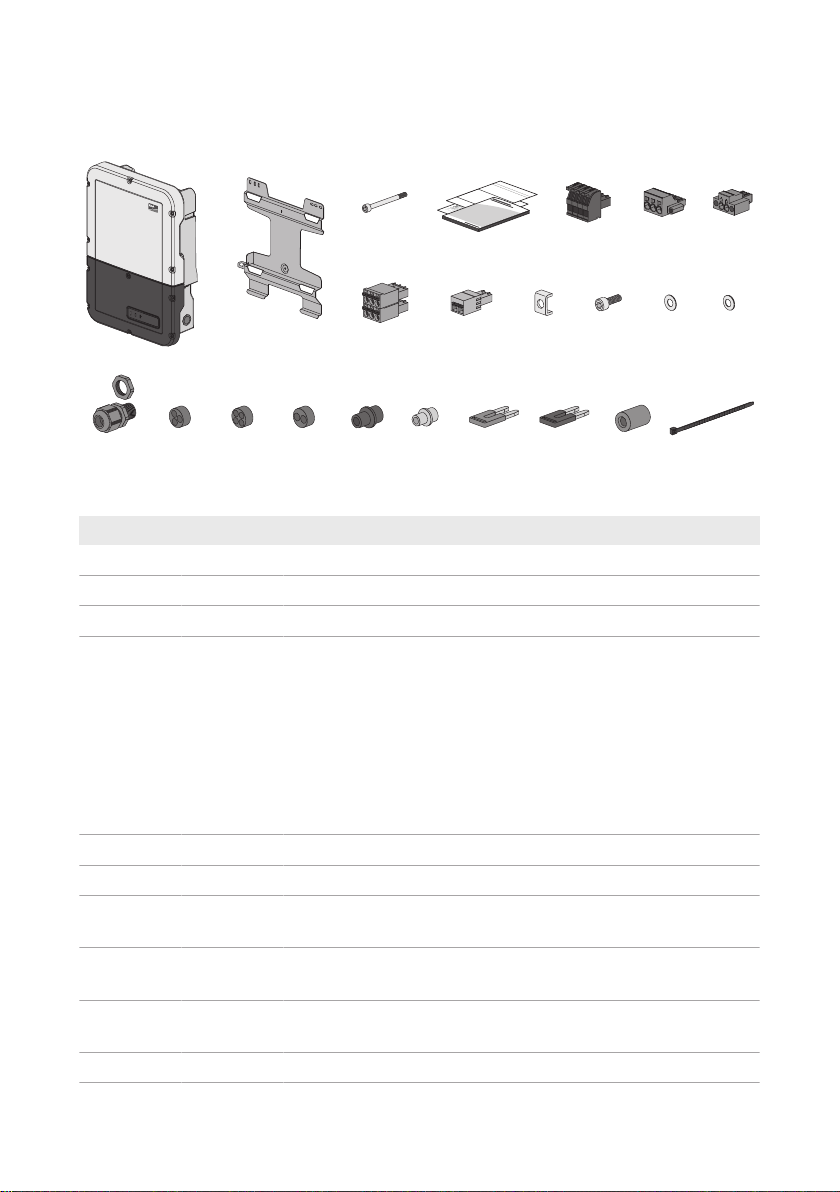
3 Scope of Delivery
Figure 1: Components included in the scope of delivery
Position Quantity Designation
A 1 Inverter
B 1 Wall mounting bracket
C 1 Cylindrical screw M5x60
D 1 Quick reference guide with password label on the rear side
The label contains the following information:
• PIC (Product Identification Code) identification key for
registering the system in SunnyPortal
• RID (Registration Identifier) registration ID for registering the
system in SunnyPortal
• WLAN password WPA2-PSK (WiFi Protected Access 2 Preshared Key) for direct connection to the inverter via WLAN
E 1 4-pole terminal block for connecting a RS485 energy meter
F 1 Terminal block for the AC connection
G 1 Terminal block for connecting the outlet for secure power supply op-
H 4 6-pole terminal block for connecting the battery communication ca-
I 1 2-pole terminal block for the switch connection for secure power
J 5 Clamping bracket
eration
bles and the communication cable of the automatic transfer switch
supply operation or for black start feature.
Operating manualSBSxx-10-BE-en-1114
SMA Solar Technology AG
3 Scope of Delivery
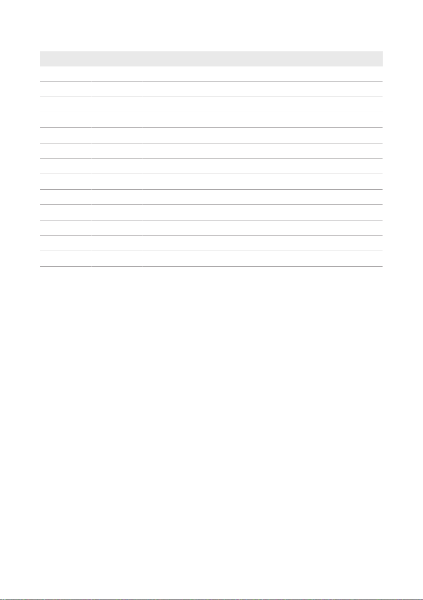
Position Quantity Designation
K 5 Cylindrical screw M5x16
L 5 Washer M5
M 5 Spring washer M5
N 6 Cable gland and counter nut PG21
O 2 Three-hole cable support sleeve
P 4 Four-hole cable support sleeve
Q 1 Two-hole cable support sleeve
R 6 Sealing plug for two-hole and three-hole cable support sleeve
S 6 Sealing plug for four-hole cable support sleeve
T 2 Blue jumper
U 2 Red jumper
V 1 Ferrite
W 1 Cable tie
Operating manual SBSxx-10-BE-en-11 15

4 Product Overview
SMA Solar Technology AG
4 Product Overview
4.1 Product Description
The SunnyBoyStorage uses the connected battery for the intermediate storage of excess PV
energy in the SMAFlexibleStorageSystem. For this purpose, the SunnyBoyStorage receives the
feed-in and purchased energy data from the energy meter. This data is used by the
SunnyBoyStorage to control the charging and discharging of the battery.
The use of an automatic transfer switching device is required in the battery-backup system. In the
event of grid failure, the automatic transfer switching device disconnects the PV system, loads and
the SunnyBoyStorage from the utility grid and creates a battery-backup grid. The battery-backup
grid supplies loads that should continue to be supplied with electricity in the event of grid failure. In
the event of grid failure, the SunnyBoyStorage supplies the loads with energy after a short
switching time. The PV system supplies additional energy that can be used to supply the loads and
charge the battery.
The use of an automatic transfer switching device is not required in limited battery-backup systems.
To build a limited battery-backup system, you must attach an outlet and a switch to the inverter. You
can connect a load to the outlet, which should continue to be supplied with power from the battery
in the event of grid failure. The secure power supply operation is not automatically enabled in the
event of a grid failure, neither is it automatically disabled once the utility grid is available again.
During secure power supply operation, the load can only be supplied with energy as long as there
is stored energy available in the battery.
Secure power supply operation in FlexibleStorageSystems with backup
power supply not possible
If the inverter is used in a battery-backup system and connected with an automatic transfer
switch, the secure power supply operation is not available.
Operating manualSBSxx-10-BE-en-1116
SMA Solar Technology AG
B
E
C
G
F
A
D
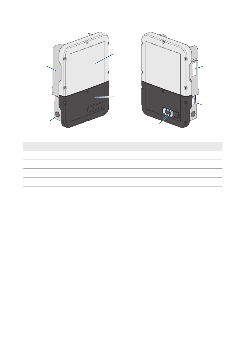
Figure 2: Design of the inverter
Position Designation
A Power Unit
B Enclosure lid of the Power Unit
C Enclosure lid for the Connection Unit
D Connection Unit
E Type label
The type label uniquely identifies the inverter. The type label must remain
permanently attached to the product. You will find the following information on the type label:
• Inverter device type (Model)
• Serial number of the PowerUnit (Serial No. Power Unit or S/N
Power Unit)
• Date of manufacture
• Device-specific characteristics
4 Product Overview
Operating manual SBSxx-10-BE-en-11 17
4 Product Overview
5 min
Position Designation
F Additional type label
The additional type label must remain permanently attached to the product. You will find the following information on the additional type label:
• Device type (Model)
• Inverter serial number (Serial number device or S/N device)
• Identification key (PIC) for registration in Sunny Portal
• Registration ID (RID) for registration in Sunny Portal
• WLAN password (WPA2-PSK) for the direct connection to the user
interface of the inverter via WLAN
G LEDs
The LEDs indicate the operating state of the inverter.
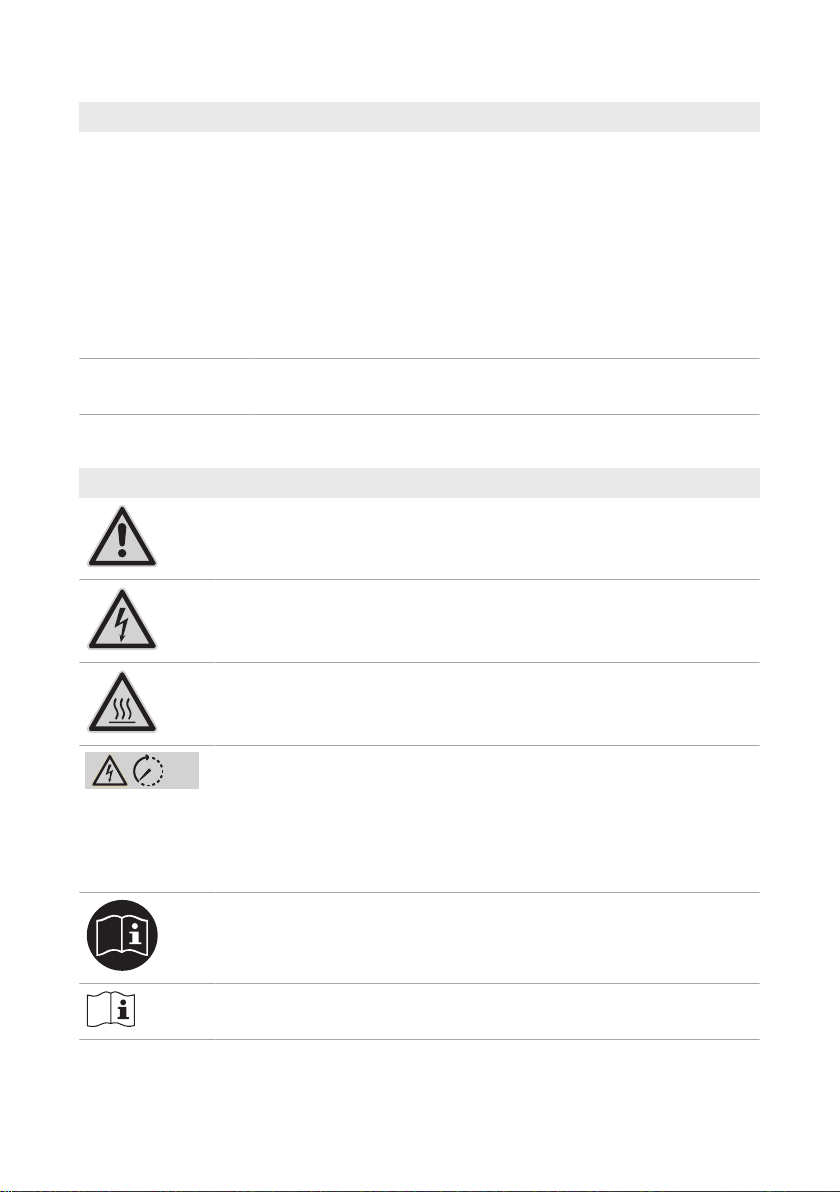
4.2 Symbols on the Product
Symbol Explanation
Beware of a danger zone
This symbol indicates that the product must be additionally grounded if addi-
tional grounding or equipotential bonding is required at the installation site.
Beware of electrical voltage
The product operates at high voltages.
SMA Solar Technology AG
Beware of hot surface
The product can get hot during operation.
Danger to life due to high voltages in the inverter; observe a waiting time of 5
minutes
High voltages that can cause lethal electric shocks are present in the live components of the inverter.
Prior to performing any work on the inverter, disconnect it from all voltage
sources as described in this document.
Observe the documentation
Observe all documentation supplied with the product.
Observe the documentation
Together with the red LED, this symbol indicates an error.
Operating manualSBSxx-10-BE-en-1118
SMA Solar Technology AG
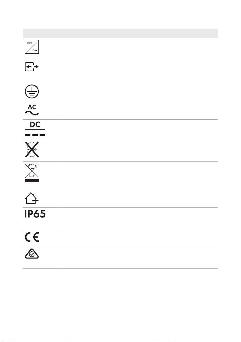
Symbol Explanation
Inverter
Together with the green LED, this symbol indicates the operating state of the in-
verter.
Data transmission
Together with the blue LED, this symbol indicates the status of the network connection.
Grounding conductor
This symbol indicates the position for connecting a grounding conductor.
Alternating current
Direct current
The product is has no galvanic isolation.
WEEE designation
Do not dispose of the product together with the household waste but in accor-
dance with the disposal regulations for electronic waste applicable at the installation site.
The product is suitable for outdoor installation.
4 Product Overview
Degree of protectionIP65
The product is protected against the penetration of dust and water that is di-
rected as a jet against the enclosure from all directions.
CE marking
The product complies with the requirements of the applicable EU directives.
RCM (Regulatory Compliance Mark)
The product complies with the requirements of the applicable Australian standards.
4.3 Interfaces and Functions
The inverter can be equipped or retrofitted with the following interfaces and functions:
Operating manual SBSxx-10-BE-en-11 19

4 Product Overview
SMA Solar Technology AG
User interface for monitoring and configuration
The product is equipped as standard with an integrated webserver, which provides a user interface
for configuring and monitoring the product. The product user interface can be called up via the web
browser if there is an existing connection to an end device (e.g. computer, tablet PC or
smartphone).
Smart Inverter Screen
The Smart Inverter Screen enables you to view the status display and to display the nominal energy
throughput and state of charge of the battery on the user interface login page. You therefore have
an overview of the most important inverter and battery data without having to log into the user
interface.
The Smart Inverter Screen is deactivated by default. The Smart Inverter Screen can be activated via
the user interface once the inverter has been commissioned.
SMA Speedwire
The product is equipped with SMASpeedwire as standard. SMASpeedwire is a type of
communication based on the Ethernet standard. SMASpeedwire is designed for a data transfer
rate of 100Mbps and enables optimum communication between Speedwire devices within
systems.
SMA Webconnect
The inverter is equipped with a Webconnect function as standard. The Webconnect function
enables direct data transmission between the inverters and Internet portals SunnyPortal and
SunnyPlaces without any additional communication device and for a maximum of 1 inverters per
visualized system. In PV systems with more than 1 inverters, there is the option of establishing data
transmission between the inverters and SunnyPortal via the data logger (e.g.,
SMADataManager) or distributing the inverters over several systems. If there is an existing WLAN
or Ethernet connection, you can directly access your visualized system via the web browser on your
end device.
WLAN
The product is equipped with a WLAN interface as standard. The inverter is delivered with the
WLAN interface activated as standard. If you do not want to use WLAN, you can deactivate the
WLAN interface.
In addition, the product has a WPS function. The WPS function is for automatically connecting the
product to a network (e.g. via router) and establish a direct connection between the product and
an end device.
Modbus
The product is equipped with a Modbus interface. The Modbus interface is deactivated by default
and must be configured as needed.
The Modbus interface of the supported SMA products is designed for industrial use – via SCADA
systems, for example – and has the following tasks:
• Remote query of measured values
• Remote setting of operating parameters
Operating manualSBSxx-10-BE-en-1120

SMA Solar Technology AG
• Setpoint specifications for system control
• Controlling the battery
4 Product Overview
Grid management services
The product is equipped with service functions for grid management.
Depending on the requirements of the grid operator, you can activate and configure the functions
(e.g. active power limitation) via operating parameters.
Secure power supply operation
In case of a grid failure, the secure power supply operation supplies the loads with energy from the
battery. You can connect a standard outlet (230V) and a standard switch to the inverter. You can
connect a load with a maximum of 16A and 230/240V to the emergency power outlet. The load
is supplied with energy from the battery during grid failure. The switch is used to enable and
disable secure power supply operation.
The secure power supply operation is not automatically enabled in the event of a grid failure,
neither is it automatically disabled once the utility grid is available again. If the utility grid fails, the
load supply must be enabled manually by activating the switch. The inverter automatically regulates
the energy supply of the outlet after activating the switch. When the utility grid is available again
and the load can be supplied by this again, the secure power supply operation must be disabled
manually by switching the switch off.
During active secure power supply operation, the inverter is disconnected from the building's main
electrical system and does not therefore feed into the utility grid. During secure power supply
operation, the load can only be supplied with energy as long as there is stored energy available in
the battery. If there is insufficient energy available from the battery, the secure power supply
operation remains active, even if the utility grid is available again. Switching over to supplying the
load from the utility grid is not carried out automatically.
Secure power supply operation in FlexibleStorageSystems with backup
power supply not possible
If the inverter is used in a battery-backup system and connected with an automatic transfer
switch, the secure power supply operation is not available.
Do not connect any loads that require an uninterrupted energy supply
The secure power supply operation and the battery-backup operation may not be used for
loads that require a uninterrupted energy supply. The energy that is available during the
secure power supply operation or battery-backup operation depends on the battery capacity
available and the state of charge of the battery (SOC).
• Do not connect loads if they are dependent on an uninterrupted energy supply for
reliable operation.
Operating manual SBSxx-10-BE-en-11 21

4 Product Overview
SMA Solar Technology AG
Battery-backup function
The inverter is equipped with a battery-backup function. The battery-backup function is disabled by
default and must be enabled via the user interface. The battery-backup function can only be
enabled if the inverter is operated in a battery-backup system with an automatic transfer switching
device. If the system is retrofitted with an automatic transfer switching device, the battery
configuration must be reset and carried out once again. Then the battery-backup system must be
configured. The configuration is carried out via the installation assistant on the user interface of the
battery inverter.
The battery-backup function ensures that the inverter forms a battery-backup grid that uses energy
from the battery and the PV system to supply the household grid in the event of a utility grid failure.
When the battery-backup operation is activated, the automatic transfer switch disconnects the PV
system and the household grid from the utility grid in the event of a grid failure, and connects these
to the battery-backup grid. After a short switch-over time, the battery-backup grid and loads
connected can be supplied by the battery and supplemented with energy from the PV system. The
charging of the battery is ensured by the existing PV system during battery-backup operation. The
charging process of the battery (initiated by the PV system) can be deactivated via a certain
parameter during battery-backup operation. As soon as the utility grid is available again, the
battery-backup operation is disabled automatically and the loads are supplied with energy from the
utility grid. If the automatic battery-backup operation is not set, the battery-backup operation must
be manually enabled in the event of a grid failure, and must also be disabled again once the utility
grid is available (information in terms of switching operations of the automatic transfer switch and
procedures during grid failure and grid reconnection see planning guidelines
"SMAFLEXIBLESTORAGESYSTEM with Battery-Backup Function").
When the utility grid is down and the battery fully discharged, there is, in the beginning, not enough
power available to create a stable battery-backup grid. In this case, the battery must be charged by
the PV system. The battery inverter is able to create a stable battery-backup grid only when enough
power is available in the battery. To use battery charging power from the PV system, the battery
inverter has to create a stand-alone grid. For this purpose, the battery inverter requires energy from
the battery reserve. If enough PV power is available, the PV inverters start automatically and the
battery is charged with energy from the PV system. The battery is charged with energy until the
battery inverter is able to provide a battery-backup grid. By setting parameters, it is possible to
define up to which state of charge the battery is charged and discharged. If not enough PV energy
is available to start the PV inverters, the stand-alone grid breaks down. Two hours later, the battery
inverter tries to start the PV inverter again to charge the battery with energy from the PV system. If
the battery inverter still fails to create a stand-alone grid after several attempts due to insufficient PV
energy, the battery inverter and battery switch to sleep mode. In this case, a manual black start is
required to switch the battery inverter and battery from sleep mode back to operation.
Secure power supply operation in FlexibleStorageSystems with backup
power supply not possible
If the inverter is used in a battery-backup system and connected with an automatic transfer
switch, the secure power supply operation is not available.
Operating manualSBSxx-10-BE-en-1122

SMA Solar Technology AG
4 Product Overview
Do not connect any loads that require an uninterrupted energy supply
The secure power supply operation and the battery-backup operation may not be used for
loads that require a uninterrupted energy supply. The energy that is available during the
secure power supply operation or battery-backup operation depends on the battery capacity
available and the state of charge of the battery (SOC).
• Do not connect loads if they are dependent on an uninterrupted energy supply for
reliable operation.
Black start function
The inverter has a black start function and an auxiliary battery that provides energy for the black
start. In battery-backup systems, you have the possibility to install a standard switch for black
starting the inverter and battery. The black-start switch is used to start the battery-backup operation
manually in the event of grid failure if the battery and inverter are in sleep mode and, therefore, are
unable to provide energy. When the black-start switch is switched on manually, the energy from the
auxiliary battery is made available in order to automatically switch the battery and therefore also
the inverter from sleep mode to operation in order that the inverter can make energy available from
the battery. You can stop the battery-backup operation by switching it off manually. To enable the
black-start function, at least one battery must be connected to input A.
Multi-battery device
The product is equipped with the multi-battery function as standard from firmware version
1.50.10.R. The multi-battery function enables to charge and discharge several batteries of the same
or different type. If the system is extended by one or several batteries or one battery is replaced,
the battery configuration must be reset and carried out again. The configuration is carried out via
the installation assistant on the user interface of the battery inverter. An overview of batteries
approved by SMA Solar Technology AG and their possible combinations is available at
www.SMA-Solar.com.
All-pole sensitive residual-current monitoring unit
The all-pole sensitive residual-current monitoring unit detects alternating and direct differential
currents. In single-phase and three-phase inverters, the integrated differential current sensor detects
the current difference between the neutral conductor and the line conductor(s). If the current
difference increases suddenly, the inverter disconnects from the utility grid.
SMA Smart Connected
SMA Smart Connected is the free monitoring of the inverter via the SMA SunnyPortal. Thanks to
SMA Smart Connected, the PV system operator and qualified person will be informed automatically
and proactively about inverter events that occur.
SMA Smart Connected is activated during registration in SunnyPortal. In order to use SMA Smart
Connected, it is necessary that the inverter is permanently connected to SunnyPortal and the data
of the PV system operator and qualified person is stored in SunnyPortal and up-to-date.
Operating manual SBSxx-10-BE-en-11 23

4 Product Overview
SMA Solar Technology AG
Time-of-Use
With the "Time-of-Use" function, you can adjust the charging behavior of the battery to your
electricity tariff. Energy bills are thus reduced and electricity at lower cost can be used. You can
determine in which time range the battery with a specified charging power is operated. At specific
times, this is mostly useful when the battery's state of charge has to take on a certain value or the
tariff situation makes the charging more attractive, regardless of the power at the grid-connection
point. The charging parameters set in the power profile are only limited by the state of charge
(SOC). At times when the "Time-of-Use" function is not enabled, the battery is charged
correspondent to the increased self-consumption for the entire system. The "Time-of-Use" function is
disabled by default and must be enabled by creating power profiles.
Peak load shaving
With the "Peak Load Shaving" function, you can optimize the behavior of the battery inverter with
respect to the power exchange at the grid-connection point. This is mostly useful when a higher
supply of energy would lead to a higher electricity cost. With the "Peak Load Shaving" function,
certain grid-exchange power outputs to which the battery inverter is adjusted depending on its
power and battery capacity available can be set. Power peaks can thus be avoided.
You can configure times and setpoints for the power drawn at the grid-connection point. When the
loads require additional energy, the battery is discharged and the maximum value is kept constant
at the grid-connection point. This is based on the prerequisite that the battery is sufficiently charged.
At times when the "Peak Load Shaving" function is not activated, the battery is charged or
discharged correspondent to the increased self-consumption for the entire system. The "Peak Load
Shaving" function is deactivated by default and must be activated by creating power profiles.
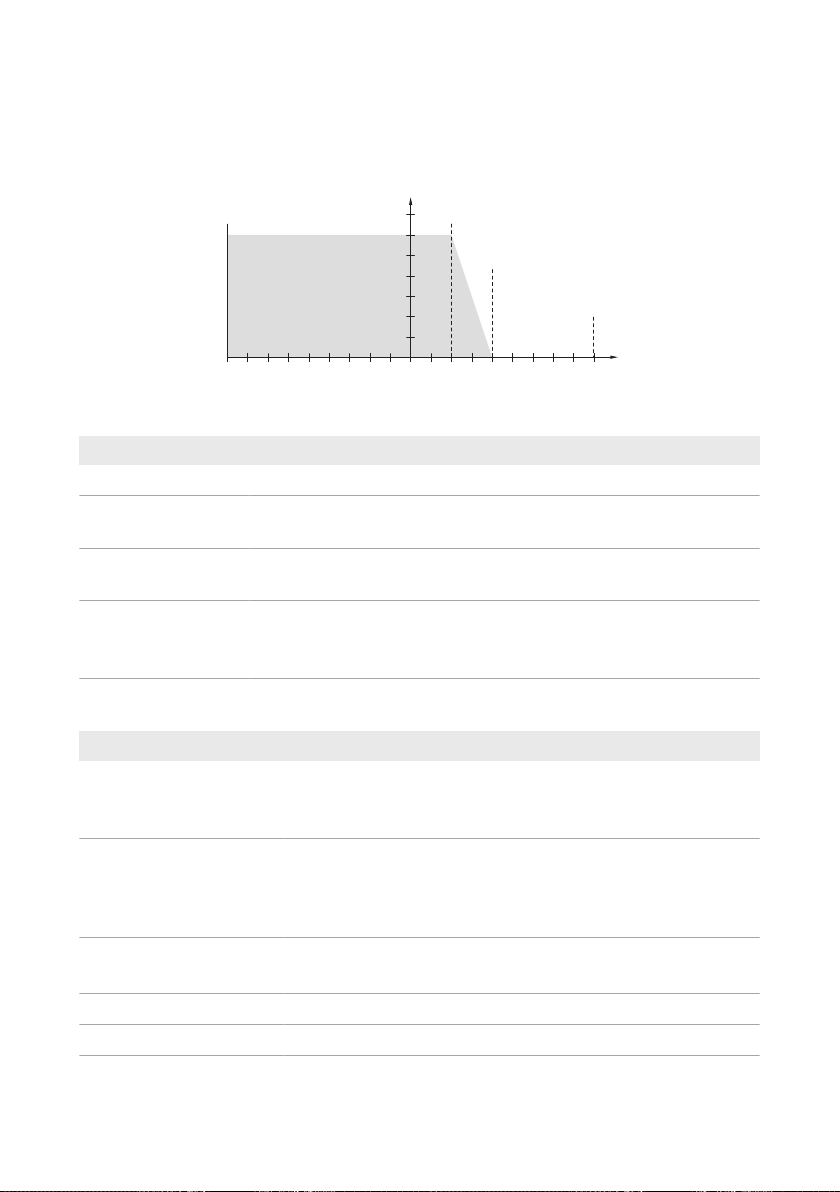
Frequency Shift Power Control
If PV inverters are connected on the AC side during battery-backup operation, the battery inverter
must be able to limit their output power. This limitation becomes necessary when, for example, the
battery inverter's battery is fully charged and the power available from the PV system exceeds the
power requirement of the connected loads.
To prevent excess energy from overcharging the battery, the battery inverter automatically detects
the problem and changes the frequency at the AC output. This frequency adjustment is analyzed by
the PV inverter. As soon as the power frequency of the battery-backup grid increases beyond the
value specified in f Start Delta, the PV inverter limits its output power accordingly.
Operating manualSBSxx-10-BE-en-1124
SMA Solar Technology AG
50
100
+4+3+2+10−1−2−3−4
f Limit Delta (2 Hz)
f Start Delta (1 Hz)
f [Hz]
PAC [%]
f Delta− (4.5 Hz)
f Delta+ (4.5 Hz)
4 Product Overview
The frequency shift power control is enabled by default. No additional settings must be carried out.
It must be ensured that the connected PV inverters limit their power at the AC output via the battery
inverter due to changes in frequency. The frequency-dependent active power limitation P(f) must be
set in the PV inverter.
Figure 3: Impact of the frequency shift power control on the power output of a PV inverter
Designation Explanation
f
fDelta- to fDelta+
Base frequency of the stand-alone grid
Maximum range in relation to the base frequency in which the PV inverter
is active.
fStartDelta
Frequency increase in relation to the base frequency, at which point the
power regulation via frequency begins.
fLimitDelta
Frequency increase in relation to the base frequency, at which point the
power regulation via frequency ends.
The power of the PV inverter at this point is 0W.
4.4 LED Signals
LED signal Explanation
The green LED is flashing
(twoseconds on and
twoseconds off)
The green LED is flashing
(1.5s on and 0.5s off)
The green LED flashes
quickly
The green LED is glowing Parallel grid operation
The green LED is off The inverter is not feeding into the utility grid.
Operating manual SBSxx-10-BE-en-11 25
Waiting for feed-in conditions
The conditions for feed-in operation are not yet met. As soon as the
conditions are met, the inverter will start feed-in operation.
Secure power supply operation or battery-backup function
The secure power supply operation or battery-backup function is activated and the inverter supplies the loads with energy from the battery.
Update of central processing unit
The central processing unit of the inverter is being updated.

4 Product Overview
LED signal Explanation
The red LED is glowing Event occurred
If an event occurs, a distinct event message and the corresponding
event number will be displayed in addition on the inverter user interface or in the communication product (e.g. SMADataManager).
The blue LED flashes slowly
for approx. one minute
Communication connection is being established
The inverter is establishing a connection to a local network or is es-
tablishing a direct connection to an end device via Ethernet (e.g.
computer, tablet PC or smartphone).
The blue LED flashes quickly
for approx. two minutes.
WPS active
The WPS function is active.
The blue LED is glowing Communication active
There is an active connection with a local network or there is a direct connection with an end device via Ethernet (e.g. computer,
tablet PC or smartphone).
SMA Solar Technology AG
Operating manualSBSxx-10-BE-en-1126
SMA Solar Technology AG
SUNNY PORTAL/
SUNNY PLACES
230 V / 16 A
SUNNY BOY
SUNNY BOY
STORAGE
ENERGY METER/
SUNNY HOME
MANAGER 2.0
Speedwire/
Ethernet
CAN
Com
INTERNET
SUNNY
TRIPOWER
UTILITY METER
FOR BILLING
PURPOSES
UTILITY GRID
PV
GENERATOR
BATTERY
APPLIANCE
Radio
DC
AC
SECURE
POWER SUPPLY
APPLIANCE
RADIO-CONTROLLED
SOCKET
PV
GENERATOR
ROUTER
(with
SWITCH)
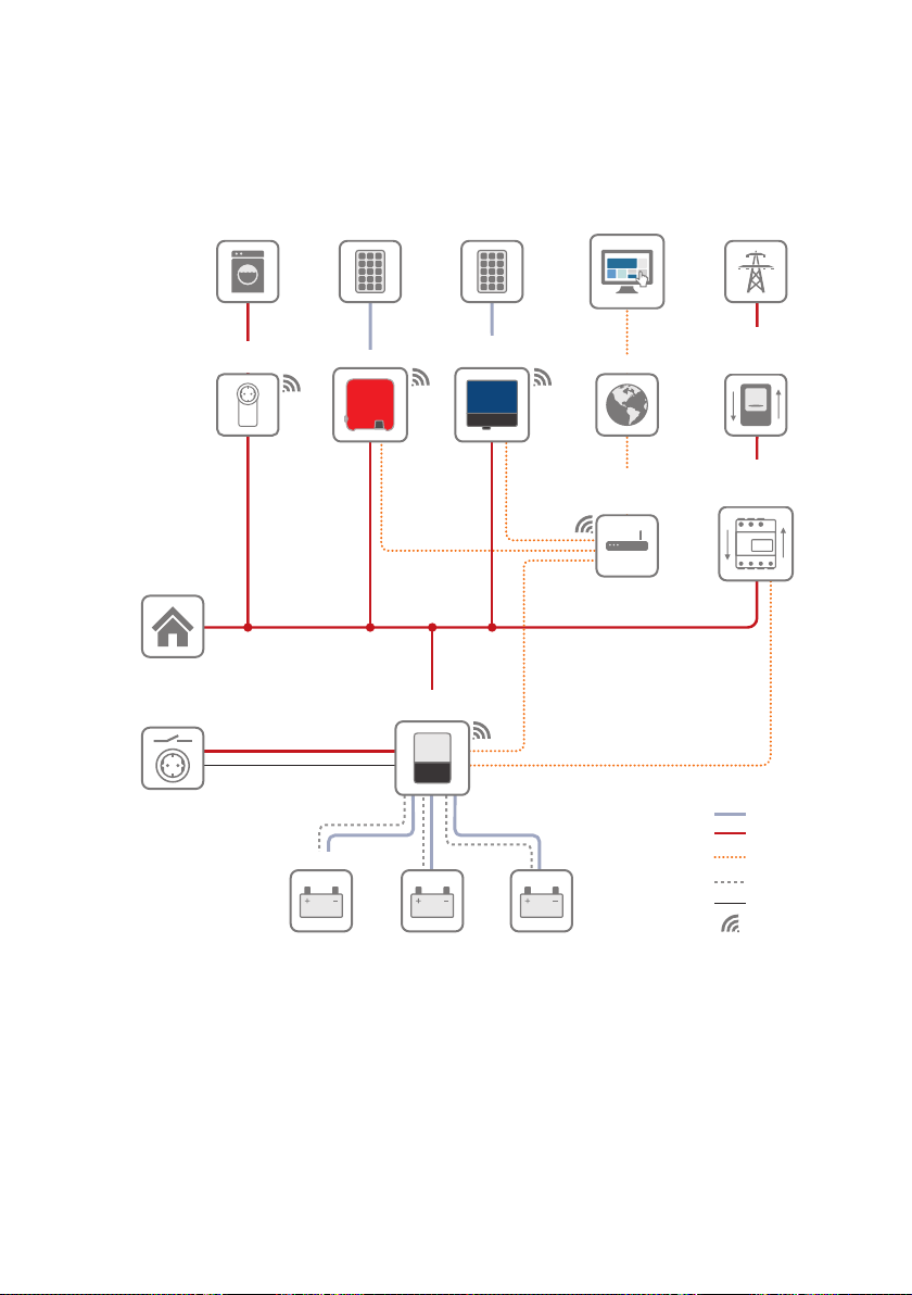
4.5 System Structure
Flexible Storage System
4 Product Overview
Figure 4: System design of a flexible storage system with switch and outlet for secure power supply operation
(example)
Operating manual SBSxx-10-BE-en-11 27
4 Product Overview
SUNNY PORTAL/
SUNNY PLACES
SUNNY BOY
SUNNY BOY
STORAGE
ENERGY METER/
SUNNY HOME
MANAGER 2.0
Speedwire/
Ethernet
CAN
Com
INTERNET
SUNNY
TRIPOWER
UTILITY METER
FOR BILLING
PURPOSES
UTILITY GRID
PV
GENERATOR
BATTERY
APPLIANCE
Radio
DC
AC
APPLIANCE
RADIO-CONTROLLED
SOCKET
PV
GENERATOR
ROUTER
(with
SWITCH)
BLACK START
SWITCH
TRANSFER
SWITCH
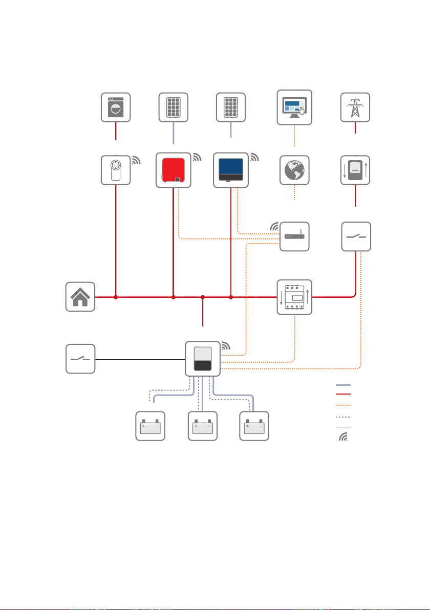
SMAFlexibleStorageSystem with Battery-Backup Function
SMA Solar Technology AG
Figure 5: System design of a flexible storage system with battery-backup function (example) You can find a
circuitry overview in the documentation of the automatic transfer switching device.
Operating manualSBSxx-10-BE-en-1128
SMA Solar Technology AG
SOC
0 %
100 %
A
E
D
B
Real SOC
User SOC
4 Product Overview
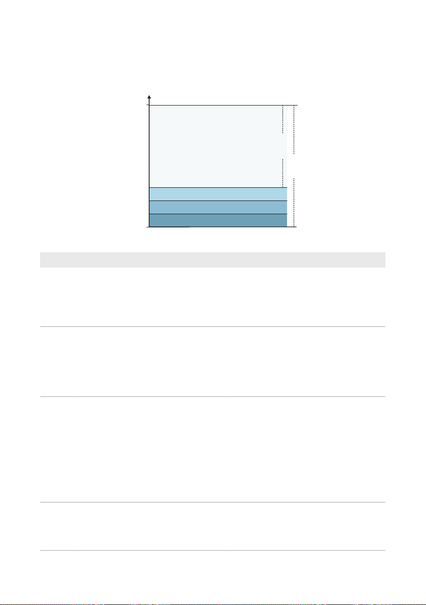
4.6 "Battery Management"
4.6.1 Battery Use by Systems for Increased Self-Consumption
Figure 6: State of charge ranges of the battery in systems for increased self-consumption without battery backup
Range Parameter Battery inverter behavior
A Self-consumption range (SlfCsmp) The battery inverter uses the batteries within
this range for increased self-consumption
and for the "Time-of-Use" and "Peak Load
Shaving" functions that can be configured
in the power profile.
B Range for maintaining battery state of
charge (PVRes)
D Minimum width of deep-discharge protec-
tion range (BatRes)
E Lower limit of the deep-discharge protec-
tion range for disconnection (ProtRes)
The battery inverter checks the current SOC
every 24 hours. If the SOC is in range D,
the batteries are recharged with 3A from
the utility grid until the upper limit of range
B is reached. If the utility grid is not available, the batteries cannot be recharged.
The battery inverter recharges the connected batteries with 3A. The recharging
process does not stop until range A is
reached.
If the utility grid is not available, the battery
inverter cannot be switched on to check the
SOC of the batteries.. The battery inverter
and batteries are switched off. Exception:
black start function
When this range is reached and the utility
grid is available, the battery inverter
charges the batteries with 3A from the utility grid until range A is reached.
Operating manual SBSxx-10-BE-en-11 29
4 Product Overview
SOC
0 %
100 %
A
E
D
B
C
Real SOC
User SOC
SMA Solar Technology AG
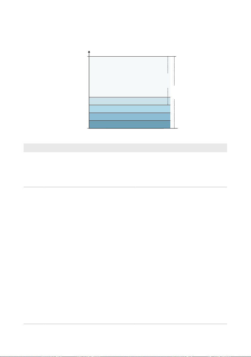
4.6.2 Battery Use by Battery-Backup Systems with Increased Self-Consumption
Figure 7: State of charge ranges of the battery in battery-backup systems
Range Parameter (technical term) Battery inverter behavior
A Self-consumption range (SlfCsmp) The battery inverter uses the batteries within
this range for increased self-consumption
and for the "Time-of-Use" and "Peak Load
Shaving" functions that can be configured
in the power profile.
C Minimum width of backup power range
(BURes)
Range for battery-backup operation during
grid failure This range is set to 0% by default. If an automatic transfer switching device is connected, the range must be set depending on your needs. The setting value
refers to the user SOC.
Utility grid available:
When the upper limit of C is reached, the
battery inverter goes into standby mode.
The batteries remain switched on. Excess
PV energy is used for conserving the battery charge.
When the SOC in range C has decreased
by the set value of range B, the battery inverter recharges the batteries with 3A from
the utility grid.
If the set value of the parameter for range
B is less than the set value of the parameter
for range C, the batteries are recharged in
range D first.
Operating manualSBSxx-10-BE-en-1130
 Loading...