

SMA Sunny Boy SB 2500, Sunny Boy SB 3000 Installation Manual
Sunny Boy SB 2500 and SB 3000
String Inverter for Photovoltaic Plants
Installation Guide Version 1.0 SB25_30-11:SE0307
IMEN-SB25_30


SMA Technolo gie AG Table of Contents
Table of Contents
1 Explanation of the Symbols Used . . . . . . . . . . . . 5
2 Foreword. . . . . . . . . . . . . . . . . . . . . . . . . . . . . . . 7
2.1 Target Group. . . . . . . . . . . . . . . . . . . . . . . . . . . . . 7
2.2 Appropriate Usage. . . . . . . . . . . . . . . . . . . . . . . . . 8
2.3 Validity of Documentation . . . . . . . . . . . . . . . . . . . . 8
3 Safety Instructions . . . . . . . . . . . . . . . . . . . . . . . . 9
4 Overview. . . . . . . . . . . . . . . . . . . . . . . . . . . . . . 11
4.1 Unit Description . . . . . . . . . . . . . . . . . . . . . . . . . . 11
4.2 External Dimensions . . . . . . . . . . . . . . . . . . . . . . . 12
5 Installation Requirements. . . . . . . . . . . . . . . . . . 13
5.1 Installation Location Requirements . . . . . . . . . . . . . 13
5.2 PV Generator Requirements . . . . . . . . . . . . . . . . . . 15
5.3 Low Voltage Grid (AC) . . . . . . . . . . . . . . . . . . . . . 15
6 Installation . . . . . . . . . . . . . . . . . . . . . . . . . . . . . 21
6.1 Mounting the Device. . . . . . . . . . . . . . . . . . . . . . . 21
6.2 Electrical Installation . . . . . . . . . . . . . . . . . . . . . . . 22
6.2.1 Connecting the AC Output . . . . . . . . . . . . . . . . . . . . . . . . . . .24
6.2.2 PV String (DC) Connection . . . . . . . . . . . . . . . . . . . . . . . . . . .30
6.3 Commissioning . . . . . . . . . . . . . . . . . . . . . . . . . . . 31
7 Opening and Closing the Sunny Boy . . . . . . . . 33
7.1 Opening the Sunny Boy . . . . . . . . . . . . . . . . . . . . 33
7.2 Closing the Sunny Boy . . . . . . . . . . . . . . . . . . . . . 33
8 Technical Data . . . . . . . . . . . . . . . . . . . . . . . . . . 35
8.1 Sunny Boy SB 2500 . . . . . . . . . . . . . . . . . . . . . . . 35
8.1.1 PV Generator Connection Data . . . . . . . . . . . . . . . . . . . . . . . .35
8.1.2 Grid Connection Data . . . . . . . . . . . . . . . . . . . . . . . . . . . . . .36
Installation Guide SB25_30-11:SE0307 Page 3

Table of Contents SMA Technologie AG
8.2 Sunny Boy SB 3000 . . . . . . . . . . . . . . . . . . . . . . . 37
8.2.1 PV Generator Connection Data . . . . . . . . . . . . . . . . . . . . . . . .37
8.2.2 Grid Connection Data . . . . . . . . . . . . . . . . . . . . . . . . . . . . . .38
8.3 General Data. . . . . . . . . . . . . . . . . . . . . . . . . . . . 39
8.3.1 Efficiency of the Sunny Boy SB 2500 . . . . . . . . . . . . . . . . . . . .40
8.3.2 Efficiency of the Sunny Boy SB 3000 . . . . . . . . . . . . . . . . . . . .41
8.4 Operating Parameters. . . . . . . . . . . . . . . . . . . . . . 42
8.4.1 Explanation of the Operating Parameters . . . . . . . . . . . . . . . . .42
8.4.2 Parameter Settings for Germany . . . . . . . . . . . . . . . . . . . . . . .45
8.4.3 Country-specific Parameter Settings . . . . . . . . . . . . . . . . . . . . .47
8.4.4 Fixed Parameters . . . . . . . . . . . . . . . . . . . . . . . . . . . . . . . . . .48
8.5 Certificate . . . . . . . . . . . . . . . . . . . . . . . . . . . . . . 49
8.5.1 CE Declaration of Conformity . . . . . . . . . . . . . . . . . . . . . . . . .49
8.5.2 SMA Grid Guard Certificate . . . . . . . . . . . . . . . . . . . . . . . . . .50
9 Replacing the Varistors . . . . . . . . . . . . . . . . . . . 51
10 Rating for a Line Circuit Breaker . . . . . . . . . . . . 55
11 The Communication Interface. . . . . . . . . . . . . . . 59
11.1 Connection of the Communication Interface. . . . . . . 60
11.1.1 Jumper Functions . . . . . . . . . . . . . . . . . . . . . . . . . . . . . . . . . .61
12 Contact. . . . . . . . . . . . . . . . . . . . . . . . . . . . . . . . 63
Page 4 SB25_30-11:SE0307 Installation Guide
SMA Technolo gie AG Explanation of the Symbols Used
1 Explanation of the Symbols Used
To ensure optimum use of this document, note the following explanation of the symbols
used.
This symbol indicates an example.
This symbol indicates a note which, if ignored, will make the procedure or
operation more difficult.
This symbol indicates a fact which, if not observed, could result in damage
to components or represent a danger to persons. Read these passages
especially carefully.
Installation Guide SB25_30-11:SE0307 Page 5

Explanation of the Symbols Used SMA Technologie AG
Page 6 SB25_30-11:SE0307 Installation Guide
SMA Technolo gie AG Foreword
2 Foreword
The Sunny Boy is equipped with the SMA grid guard. This is a type of automatic
disconnection device. This means that the Sunny Boy complies with the VDEW
(Verband der Elektrizitätswirtschaft – German Electricity Industry Association)
regulations for the connection and parallel operation of power-generating systems
to the low-voltage grid of the energy supply company and with DIN VDE 0126-11, which forms part of these regulations.
Refer to the operating manual for detailed information on troubleshooting and
operating the Sunny Boy as well as on the various communication options.
Sunny Design will assist you in the system design and checking of the string size for a
given type of inverter. Further information on Sunny Design is available at
www.SMA.de.
If you require further information, please call the Sunny Boy Hotline:
+49 (561) 95 22 - 499
2.1 Target Group
Warning!
The Sunny Boy may only be installed by trained specialists. The installer
must be approved by the local energy supplier. Read this installation
guide carefully. Ensure compliance with all prescribed safety regulations,
the technical connection requirements of the local energy supplier and
any other applicable provisions.
This installation guide is exclusively intended for qualified electricians and is intended
to assist with the speedy and correct installation and commissioning of the SMA Sunny
Boy SB 2500 and Sunny Boy SB 3000 inverters.
Installation Guide SB25_30-11:SE0307 Page 7

Foreword SMA Technologie AG
2.2 Appropriate Usage
Warning!
The Sunny Boy is designed for operation in grid-connected PV systems.
Use of the Sunny Boy for any purpose other than those specified in this
documentation will lead to the loss of the right to all warranty claims and
may lead to a fault in the device. This includes, among other things, the
operation with voltage sources without any current limit. When in doubt,
contact SMA.
2.3 Validity of Documentation
The Sunny Boy SB 2500 and Sunny Boy SB 3000 are identical in construction and only
differ in their technical data. This documentation uses the terms Sunny Boy or inverter
when referring to either device type. The device will be specified with its full name if the
information only refers to that particular device.
Page 8 SB25_30-11:SE0307 Installation Guide
SMA Technolo gie AG Safety Instructions
3 Safety Instructions
Warning! Overvoltage!
Check the system design using the Sunny
Design tool (www.SMA.de) or by calling
the Sunny Boy Hotline. Overvoltages lead
to the destruction of the Sunny Boy.
Warning! High voltage!
Work on the Sunny Boy with the cover removed must be carried out by a
qualified electrician! High voltages are present in the device. Work is to
be carried out on the Sunny Boy only once the AC and DC voltages have
been disconnected from the Sunny Boy, and once it has been ensured that
the capacitors have been discharged.
The Sunny Boy must be disconnected from the grid and precautions must
be taken to prevent the grid being accidentally reconnected. In addition,
the connections to the PV generator must be disconnected.
After isolating the AC and DC voltage, you must wait approximately 30
minutes for the capacitors in the Sunny Boy to discharge. Only then is it
safe to open the unit by removing the cover to make sure that no voltage
is present in the device.
Warning! Electrostatic charge!
When working on the Sunny Boy and handling its assemblies, remember
to observe all ESD safety regulations. Electronic components are
susceptible to electrostatic charge. Discharge any electrostatic charge by
touching the grounded housing before handling any electronic
component.
Installation Guide SB25_30-11:SE0307 Page 9

Safety Instructions SMA Technologie AG
Page 10 SB25_30-11:SE0307 Installation Guide
SMA Technolo gie AG Overview
4 Overview
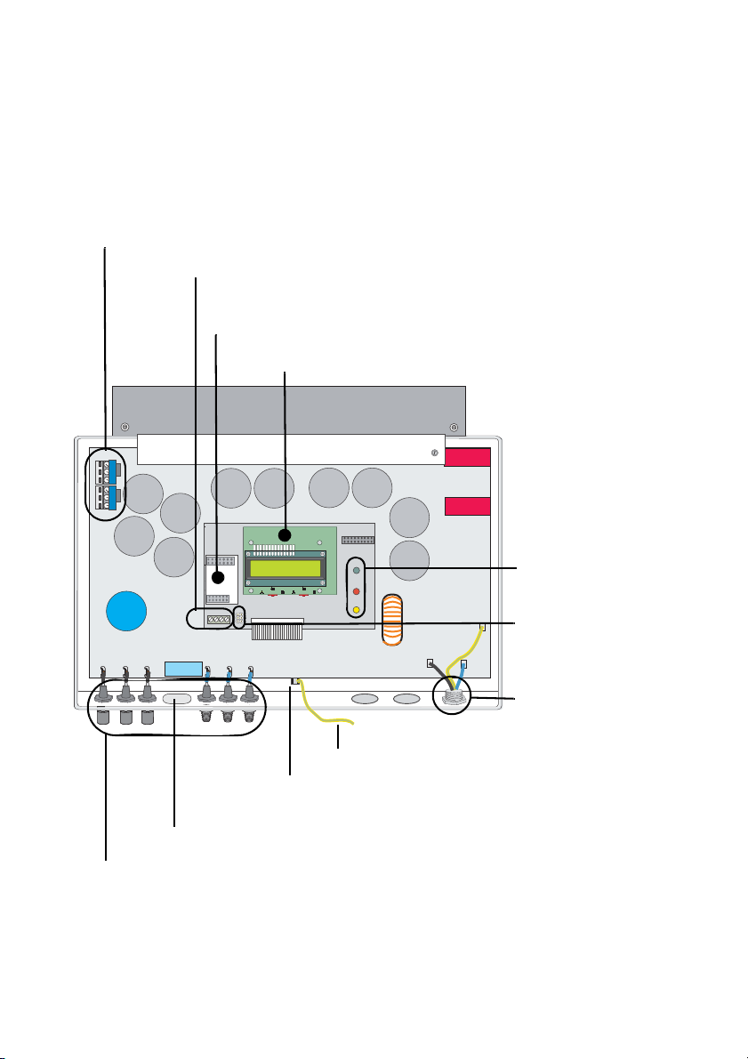
4.1 Unit Description
The following diagram gives a schematic overview of the various components and
connection points inside the Sunny Boy with the cover removed:
Varistors, section 9
Communication socket
Communication socket (RS232, RS485, NLM
Piggy-Back, radio), section 11
Sunny Display
Operating status
LEDs
Jumper slot for
communication
Plug socket (AC),
section 6.2.1
PE (protective earth) connector for cover
Flat plug connection for grounding the cable shield for
RS232 and RS485 communication
Housing feed-through for the optional Electronic Solar Switch
PV input plugs (DC), section 6.2.2
Installation Guide SB25_30-11:SE0307 Page 11
Overview SMA Technologie AG
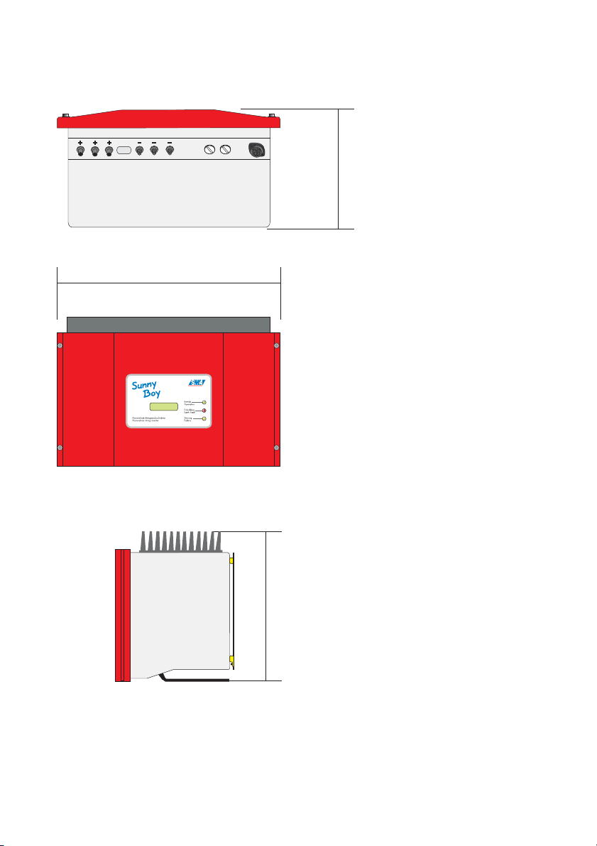
4.2 External Dimensions
225 mm
470 mm
490 mm
Page 12 SB25_30-11:SE0307 Installation Guide
SMA Technolo gie AG Installation Requirements
5 Installation Requirements
Check that all of the requirements listed below are met before installing and
commissioning the Sunny Boy.
5.1 Installation Location Requirements
The Sunny Boy SB 2500 weighs 30 kg, the Sunny Boy SB 3000
weighs 32 kg. Take this weight into account when choosing the
installation location and method of installation.
The ambient temperature must not be outside the -25 °C to
+60 °C range.
The Sunny Boy is designed for outdoor installation and should be
30 / 32 kg
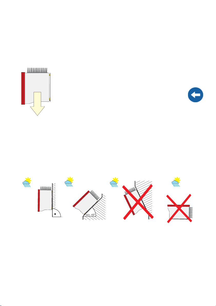
The Sunny Boy is designed to be mounted on a vertical wall. However, if absolutely
necessary, the Sunny Boy can be installed tilted back at a maximum angle of 45°.
Vertical installation at eye-level is preferable for an optimum energy yield and maximum
operational comfort. If installing the unit outdoors, make sure that it is not slanting
forwards.
We advise against installing the unit in a horizontal position outdoors.
installed in a place where it is not exposed to direct sunlight. An
increased ambient temperature can reduce the yield of the PV
system. Installing the unit in badly ventilated, warm indoor locations
may also reduce yield.
Install the inverter vertically or
tilting backward.
Installation Guide SB25_30-11:SE0307 Page 13
Never install the inverter horizontally
or so that it tilts forward.
Installation Requirements SMA Technologie AG
When choosing the installation location, be sure to observe the
following:
Warning, high voltage!
Unintentionally pulling out the DC plug connectors under load can
damage the plugs and could result in personal injury! Install the Sunny
Boy in such a way that it is not possible (e.g. for children) to unplug the
DC plug connector unintentionally.
Warning, risk of burning!
The temperature of the individual components in the housing, especially
the heatsinks, can exceed 60 °C. There is the danger of burn injury when
these parts are touched!
Warning!
Do not install the Sunny Boy on flammable construction materials, in areas
where highly inflammable materials are stored or in potentially explosive
environments!
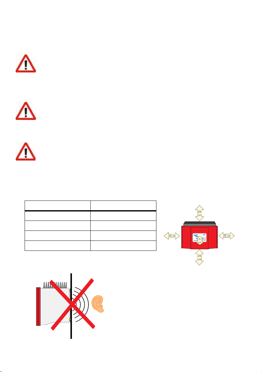
When choosing the installation location, ensure there is enough space for heat to
dissipate! Under normal conditions, the following recommended values for the space
to be kept clear around the Sunny Boy should be followed:
Minimum clearance
Sides 20 cm
Top 20 cm
Underneath 20 cm
Front 5 cm
In a living area, the unit should not be mounted on
plasterboard walls or alike as otherwise audible
vibrations are likely to result.
We recommend securing the unit to a solid surface.
The Sunny Boy can make noises during operation
which could be perceived as a nuisance if installed
in a living area.
Page 14 SB25_30-11:SE0307 Installation Guide
SMA Technolo gie AG Installation Requirements
5.2 PV Generator Requirements
The Sunny Boy is designed to be connected to up to three strings (PV modules wired in
series) having a homogenous structure (modules of the same type, identical orientation
and tilt).
Sunny Design will assist you in the system design and checking of the string size for a
given type of inverter. Further information on Sunny Design is available at
www.SMA.de.
The unit has six DC plug connectors (two for each string) for connecting the PV
generators. The connecting cables from the PV generators must also be fitted with this
type of plug connector. A pre-assembled set for connecting the free cable ends from a
string is available as an optional accessory. The SMA order codes for the various
connectors are as follows:
• Multi-Contact 3 mm: SWR-MC
• Multi-Contact 4 mm: MC-SET
• Tyco: TYCO-SET
Limit values for DC input
Max. voltage 600 V (DC)
Max. input current 12 A (DC)
5.3 Low Voltage Grid (AC)
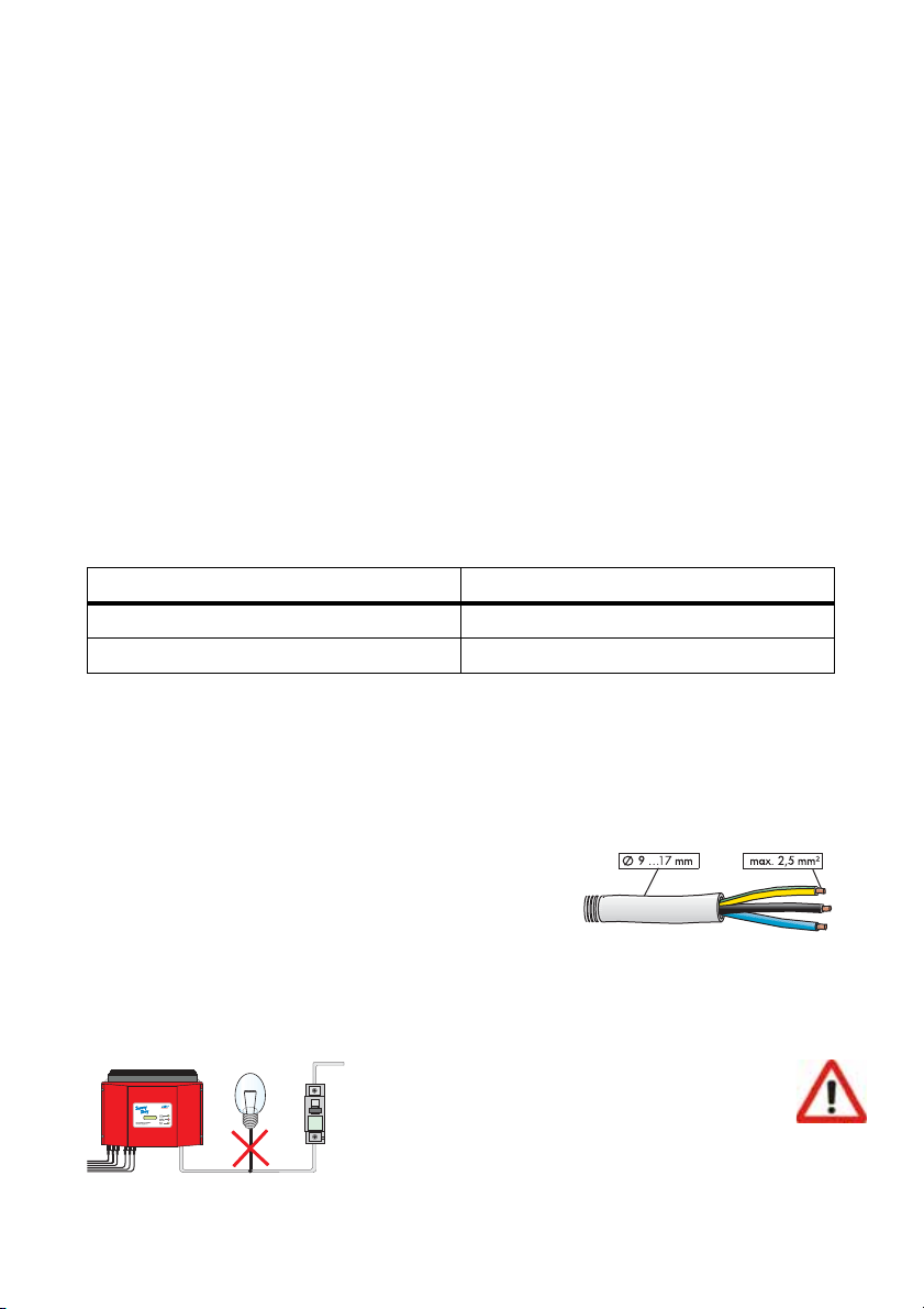
The Sunny Boy must have a three-conductor connection to the grid (live (L), neutral (N),
protective earth (PE)).
The grid connection terminals on the AC connection
socket included in the accessories kit can take wires
with a cross-section of up to 2.5 mm². The
accessories kit also contains a PG13.5 AC
connection socket for connecting cables with a crosssection between 9 mm² and 13.5 mm², while the
PG16 connection socket is used for cables with a
cross-section up to a maximum of 17 mm². For detailed instructions, see sections
"Connecting the AC Output with PG13.5" (Page 26) and "Connecting the AC Output
with PG16" (Page 28).
Warning!
We recommend using a 16 A line circuit
breaker to protect the power circuit. No
loads should be connected to this power
circuit.
Installation Guide SB25_30-11:SE0307 Page 15
Cable
diameter
Wire
cross-section

Installation Requirements SMA Technologie AG
Rating for a Line Circuit Breaker in a Photovoltaic Power Generating
System Operated in Parallel to the Low Voltage Grid
Various factors should be taken into account when selecting line circuit breakers. These
include, for example:
• The type of cable used (conductor material and insulation)
• Ambient temperatures affecting the cables (higher temperatures result in a reduced
maximum current load)
• Method of routing the cable (reduces the maximum current load)
• Bundling cables together (reduces the maximum current load)
• Loop impedance [Z] (in the event of a body contact this limits the current that can
flow and therefore determines the response behavior of the circuit breaker)
• Sufficient distance between the circuit breakers so as to avoid undue heating (heat
can trigger the circuit breaker early)
•Selectivity
• Protection class of the connected load (VDE 0100, part 410), Protection against
electric shock
Please pay attention to section 10 "Rating for a Line Circuit Breaker" (Page 55).
The following standards should be followed in all cases:
• DIN VDE 0298-4 (Cable routing and current-carrying capacity)
• DIN VDE 0100, part 430 (Protective measures; protection of cable and
cords against overcurrent)
• DIN VDE 0100, part 410 (Protective measures; protection against electric
shock)
Page 16 SB25_30-11:SE0307 Installation Guide
SMA Technolo gie AG Installation Requirements
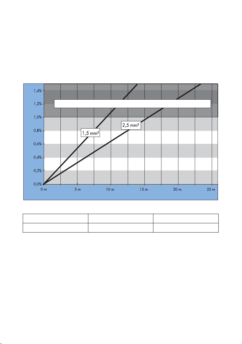
For optimum operation of the inverters, the grid impedance of the AC cable must not
exceed 1 Ohm. This is necessary, amongst other things, for the correct operation of the
impedance monitoring. In addition, we recommend dimensioning the cable crosssection so that output losses do not exceed 1 % at nominal power. Output losses as a
function of cable length and cross-section are shown in the graphs below. Multi-wire
cables with copper forward and return conductors are used.
Output Losses of the Sunny Boy SB 2500
Do not use cables where losses will exceed 1.0 %
Output losses
Cable length
The maximum cable lengths for the different cable cross-sections are as follows:
Cable cross-section 1.5 mm² 2.5 mm²
Max. length 9 m 15.5 m
Installation Guide SB25_30-11:SE0307 Page 17
Installation Requirements SMA Technologie AG
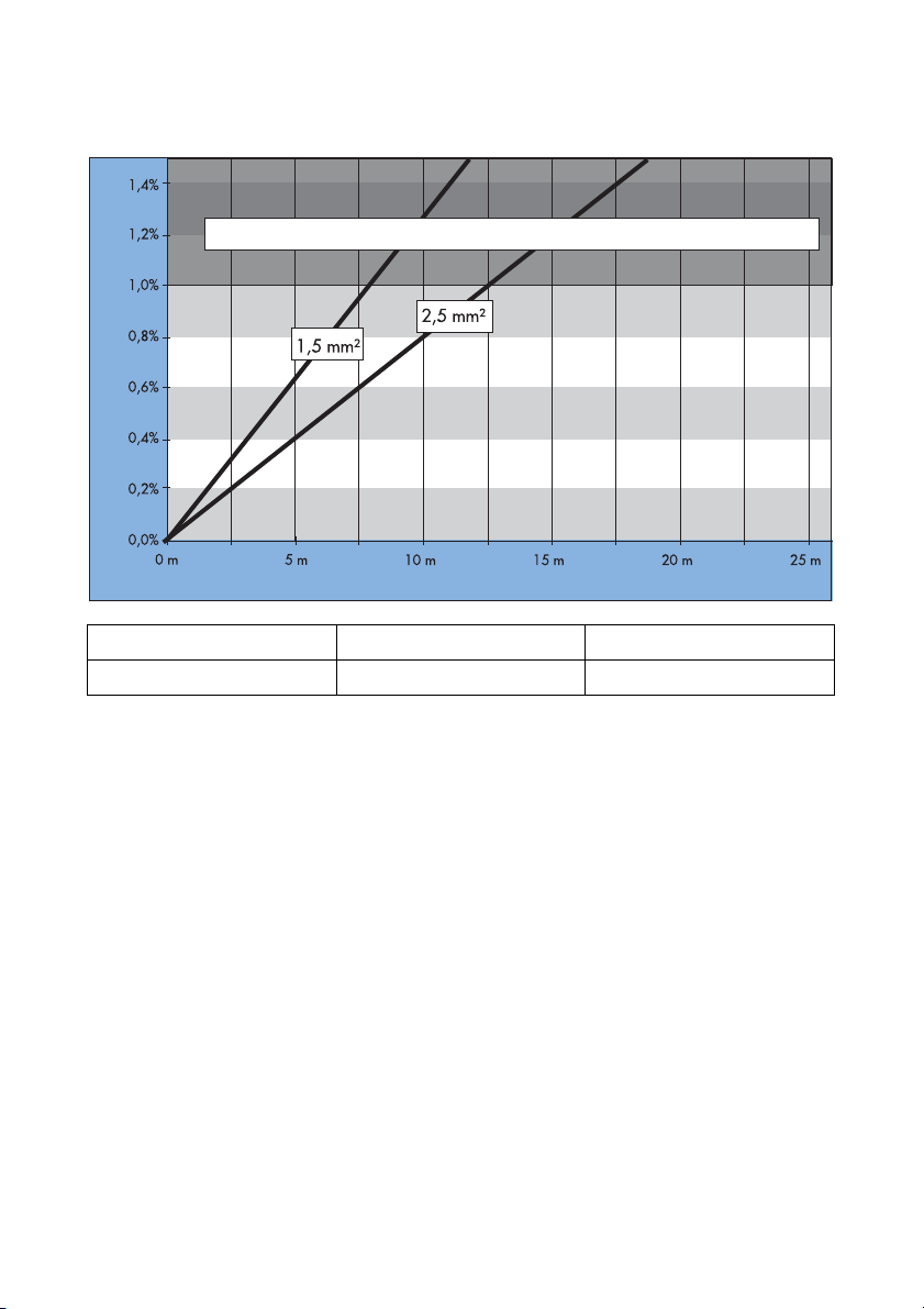
Output Losses of the Sunny Boy SB 3000
Do not use cables where losses will exceed 1.0 %
Output losses
Cable length
Cable cross-section 1.5 mm² 2.5 mm²
Max. length 7.5 m 12.5 m
Page 18 SB25_30-11:SE0307 Installation Guide
SMA Technolo gie AG Installation Requirements
The Sunny Boy is designed for operation on 220 - 240 V grids at a grid frequency of
50 / 60 Hz. When connecting an inverter to the public grid, follow the connection
requirements of the local grid operator.
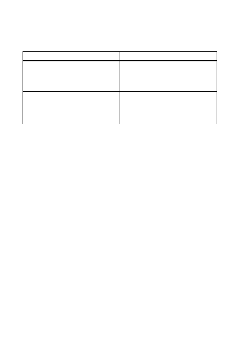
Limit values for AC output
Voltage range (complying with DIN VDE
198 V ... 253 / 260 V
a
0126-1-1)
Frequency range (complying with DIN
47.55 Hz ... 50.2 Hz
VDE 0126-1-1)
Voltage range (extended operating
180 V ... 265 V
range)
Frequency range (extended operating
range)
45.5 Hz ... 54.5 Hz
55.5 Hz ... 64.5 Hz
a The Sunny Boy can feed into the public grid at a maximum output voltage of
260 V for brief periods. However, DIN VDE 0126-1-1 stipulates that the 10minute average must not exceed a voltage of 253 V. That means, if the grid
voltage is constantly 254 V (e.g.), the inverter disconnects itself from the grid.
In this case, contact the local grid operator for assistance.
DIN VDE 0126-1-1 only applies in Germany. See section 8.4.3 "Countryspecific Parameter Settings" (Page 47) for all other preset country values of
your inverter.
Installation Guide SB25_30-11:SE0307 Page 19

Installation Requirements SMA Technologie AG
Page 20 SB25_30-11:SE0307 Installation Guide
 Loading...