

SMA SUNNY BOY 5000-US, SUNNY BOY 6000-US, SUNNY BOY 7000-US, SUNNY BOY 8000-US Installation Manual
SB50US-80US-IA-en-36 | TBUS-SB50_60_70US | Version 3.6
CA
US
PV Inverter
SUNNY BOY 5000-US / 6000-US / 7000-US / 8000-US
Installation Manual


SMA America, LLC Legal Restrictions
Installation Manual SB50US-80US-IA-en-36 3
Copyright © 2011 SMA America,LLC. All rights reserved.
No part of this document may be reproduced, stored in a retrieval system, or transmitted, in any form
or by any means, electronic, mechanical, photographic, magnetic or otherwise, without the prior
written permission of SMA America,LLC.
Neither SMA America,LLC nor SMA Solar Technology Canada Inc. makes representations, express
or implied, with respect to this documentation or any of the equipment and/or software it may
describe, including (with no limitation) any implied warranties of utility, merchantability, or fitness for
any particular purpose. All such warranties are expressly disclaimed. Neither SMA America,LLC nor
its distributors or dealers nor SMA Solar Technology Canada Inc. nor its distributors or dealers shall
be liable for any indirect, incidental, or consequential damages under any circumstances.
(The exclusion of implied warranties may not apply in all cases under some statutes, and thus the
above exclusion may not apply.)
Specifications are subject to change without notice. Every attempt has been made to make this
document complete, accurate and up-to-date. Readers are cautioned, however, that
SMAAmerica,LLC and SMA Solar Technology Canada Inc. reserve the right to make changes
without notice and shall not be responsible for any damages, including indirect, incidental or
consequential damages, caused by reliance on the material presented, including, but not limited to,
omissions, typographical errors, arithmetical errors or listing errors in the content material.
All trademarks are recognized even if these are not marked separately. Missing designations do not
mean that a product or brand is not a registered trademark.
The Bluetooth
®
word mark and logos are registered trademarks owned by Bluetooth SIG, Inc. and
any use of such marks by SMA America,LLC and SMA Solar Technology Canada Inc. is under
license.
SMA America, LLC
3801 N. Havana Street
Denver, CO 80239 U.S.A.
SMA Solar Technology Canada Inc.
2425 Matheson Blvd. E, 8th Floor
Mississauga, ON L4W 5K5, Canada
Important Safety Instructions SMA America, LLC
4 SB50US-80US-IA-en-36 Installation Manual
IMPORTANT SAFETY INSTRUCTIONS
SAVE THESE INSTRUCTIONS
This manual contains important instructions for Sunny Boy inverter, that must be followed during
installation and maintenance of the inverter.
The Sunny Boy is designed and tested according to international safety requirements, but as with all
electrical and electronic equipment, certain precautions must be observed when installing and/or
operating the Sunny Boy. To reduce the risk of personal injury and to ensure the safe installation and
operation of the Sunny Boy, you must carefully read and follow all instructions, cautions and warnings
in this installation guide.
Warnings in this document
A warning describes a hazard to equipment or personnel. It calls attention to a procedure or practice,
which, if not correctly performed or adhered to, could result in damage to or destruction of part or all
of the SMA equipment and/or other equipment connected to the SMA equipment or personal injury.
DANGER
DANGER indicates a hazardous situation which, if not avoided, will result in death or
serious injury.
WARNING
WARNING indicates a hazardous situation which, if not avoided, could result in death or
serious injury.
CAUTION
CAUTION indicates a hazardous situation which, if not avoided, could result in minor or
moderate injury.
NOTICE
NOTICE is used to address practices not related to personal injury.
SMA America, LLC Important Safety Instructions
Installation Manual SB50US-80US-IA-en-36 5
Other symbols in this document
In addition to the safety and hazard symbols described on the previous pages, the following symbol
is also used in this installation guide:
Markings on this product
The following symbols are used as product markings with the following meanings.
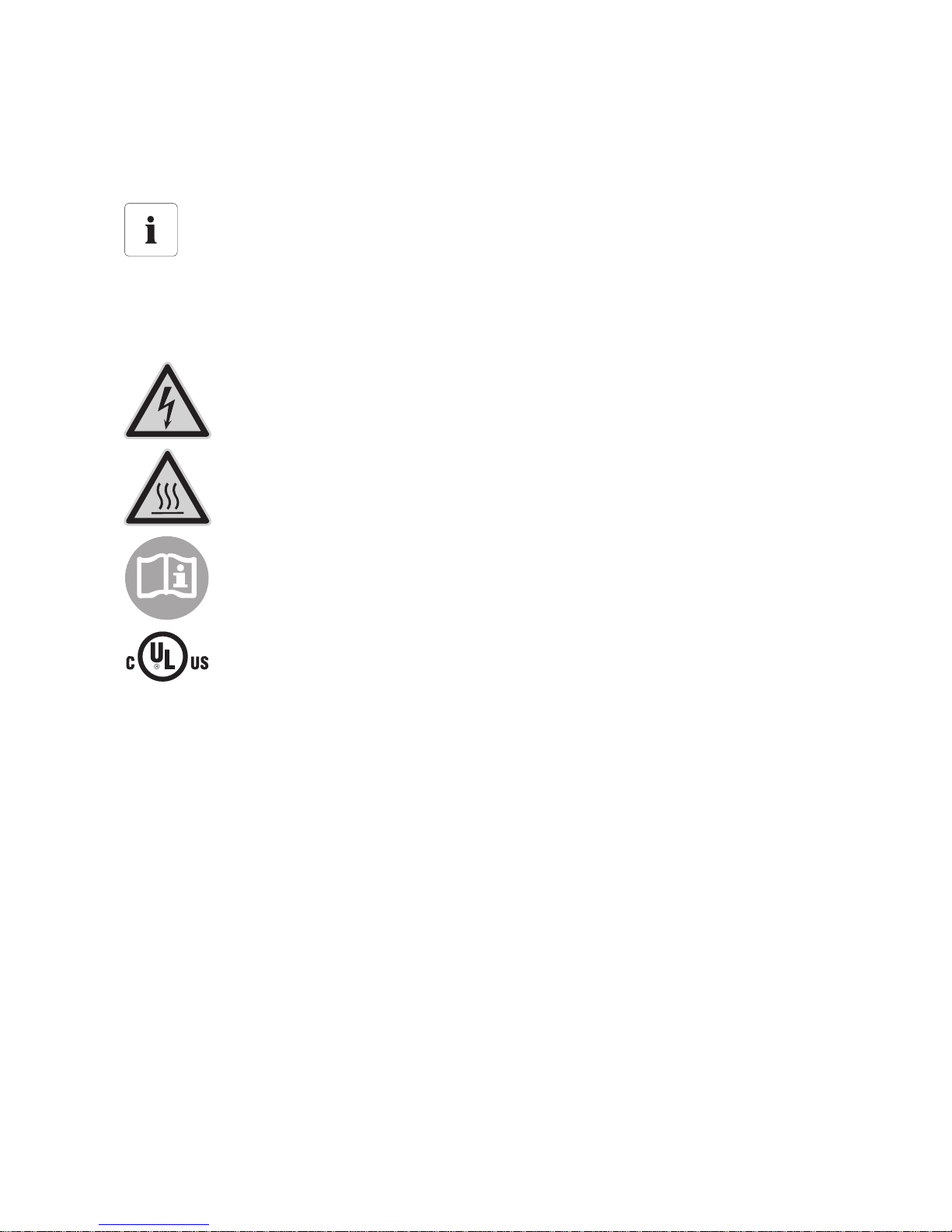
Information
This symbol accompanies notes that call attention to supplementary information that you
must know and use to ensure optimal operation of the system.
Warning regarding dangerous voltage
The product works with high voltages. All work on the product must only be performed
as described in the documentation of the product.
Beware of hot surface
The product can become hot during operation. Do not touch the product during
operation.
Observe the operating instructions
Read the documentation of the product before working on it. Follow all safety
precautions and instructions as described in the documentation.
This inverter is evaluated to UL 1741, which includes assessment to all of the
requirements of IEEE1547 and IEEE1547.1, which are an outgrowth and further
development of the IEEE recommended practices and guidelines contained in IEEE Std.
929-2000. IEEE 929-2000 provides recommendations regarding the proper equipment
and functionality necessary to ensure compatible operation when power generation is
connected to the utility grid. The inverter is additionally evaluated to the
NationalElectricalCode® and the Canadian Electrical Code® CSA C22.2 No.
107.1‑1.
General Warnings SMA America, LLC
6 SB50US-80US-IA-en-36 Installation Manual
General warnings
General warnings
All electrical installations must be done in accordance with the local and
NationalElectrical Code
®
ANSI/NFPA 70 or the Canadian Electrical Code®
CSAC22.1. This document does not and is not intended to replace any local, state,
provincial, federal or national laws, regulation or codes applicable to the installation and
use of the inverter, including without limitation applicable electrical safety codes. All
installations must conform with the laws, regulations, codes and standards applicable in
the jurisdiction of installation. SMA assumes no responsibility for the compliance or
noncompliance with such laws or codes in connection with the installation of the inverter.
The Sunny Boy contains no user-serviceable parts except for the fans on the bottom of the
enclosure and the filters behind the fans as well as the handle covers on the sides of the
unit. For all repair and maintenance, always return the unit to an authorized SMA Service
Center.
Before installing or using the Sunny Boy, read all of the instructions, cautions, and warnings
on the Sunny Boy in this installation guide.
Before connecting the Sunny Boy to the electrical utility grid, contact the local utility
company. This connection must be made only by qualified personnel.
Wiring of the Sunny Boy must be made by qualified personnel only.

SMA America, LLC Table of Contents
Installation Manual SB50US-80US-IA-en-36 7
Table of Contents
1 Information on this Manual. . . . . . . . . . . . . . . . . . . . . . . . 11
1.1 Validity . . . . . . . . . . . . . . . . . . . . . . . . . . . . . . . . . . . . . . . . . . . 11
1.2 Target Group . . . . . . . . . . . . . . . . . . . . . . . . . . . . . . . . . . . . . . 11
1.3 Storing the Documentation . . . . . . . . . . . . . . . . . . . . . . . . . . . . 11
1.4 Additional Information . . . . . . . . . . . . . . . . . . . . . . . . . . . . . . . 11
1.5 Nomenclature. . . . . . . . . . . . . . . . . . . . . . . . . . . . . . . . . . . . . . 11
2 Safety . . . . . . . . . . . . . . . . . . . . . . . . . . . . . . . . . . . . . . . . . 12
2.1 Intended Use. . . . . . . . . . . . . . . . . . . . . . . . . . . . . . . . . . . . . . . 12
2.2 Safety Instructions . . . . . . . . . . . . . . . . . . . . . . . . . . . . . . . . . . . 14
2.3 Installation Overview . . . . . . . . . . . . . . . . . . . . . . . . . . . . . . . . 15
3 Unpacking and Inspection. . . . . . . . . . . . . . . . . . . . . . . . . 16
3.1 Scope of Delivery . . . . . . . . . . . . . . . . . . . . . . . . . . . . . . . . . . . 16
4 AC Voltage Configuration . . . . . . . . . . . . . . . . . . . . . . . . . 17
4.1 Opening the Sunny Boy . . . . . . . . . . . . . . . . . . . . . . . . . . . . . . 17
4.2 Locating Internal Component Parts . . . . . . . . . . . . . . . . . . . . . . 18
4.3 AC Voltage Configuration . . . . . . . . . . . . . . . . . . . . . . . . . . . . 19
4.4 Jumper for System Configuration . . . . . . . . . . . . . . . . . . . . . . . 22
5 Assembly. . . . . . . . . . . . . . . . . . . . . . . . . . . . . . . . . . . . . . . 24
5.1 Safety . . . . . . . . . . . . . . . . . . . . . . . . . . . . . . . . . . . . . . . . . . . . 24
5.2 Requirements for the Mounting Location. . . . . . . . . . . . . . . . . . 25
5.3 Mounting with Wall Mounting Bracket. . . . . . . . . . . . . . . . . . . 27
5.3.1 Possibilities for Mounting the Wall Mounting Bracket. . . . . . . . . . . . . . . . . . 29
5.3.2 Mounting the Wall Mounting Bracket. . . . . . . . . . . . . . . . . . . . . . . . . . . . . . 30
5.4 Mounting the DC Disconnect . . . . . . . . . . . . . . . . . . . . . . . . . . 30
5.4.1 Mounting the DC disconnect. . . . . . . . . . . . . . . . . . . . . . . . . . . . . . . . . . . . . 32
5.4.2 Mounting the Sunny Boy on a Wall Mounting Bracket . . . . . . . . . . . . . . . . 33

Table of Contents SMA America, LLC
8 SB50US-80US-IA-en-36 Installation Manual
6 Electrical Connection . . . . . . . . . . . . . . . . . . . . . . . . . . . . . 34
6.1 Connection Area of the Sunny Boy. . . . . . . . . . . . . . . . . . . . . . 36
6.2 Sunny Boy Circuit Diagrams . . . . . . . . . . . . . . . . . . . . . . . . . . . 37
6.2.1 Wiring with DC disconnect . . . . . . . . . . . . . . . . . . . . . . . . . . . . . . . . . . . . . . 38
6.3 Opening the Sunny Boy . . . . . . . . . . . . . . . . . . . . . . . . . . . . . . 39
6.4 Opening the DC Disconnect. . . . . . . . . . . . . . . . . . . . . . . . . . . 40
6.5 AC Connection . . . . . . . . . . . . . . . . . . . . . . . . . . . . . . . . . . . . . 41
6.5.1 AC Connection Requirements . . . . . . . . . . . . . . . . . . . . . . . . . . . . . . . . . . . . 41
6.5.2 AC Connection in the DC Disconnect . . . . . . . . . . . . . . . . . . . . . . . . . . . . . . 42
6.5.3 Connecting the AC Cables in the Sunny Boy . . . . . . . . . . . . . . . . . . . . . . . . 44
6.6 DC Connection . . . . . . . . . . . . . . . . . . . . . . . . . . . . . . . . . . . . . 46
6.6.1 DC Connection Requirements . . . . . . . . . . . . . . . . . . . . . . . . . . . . . . . . . . . . 47
6.6.2 DC Input Grounding . . . . . . . . . . . . . . . . . . . . . . . . . . . . . . . . . . . . . . . . . . . 48
6.6.3 Connecting the DC Cables in the DC disconnect . . . . . . . . . . . . . . . . . . . . . 49
6.6.4 DC Connection with Additional DC Distribution . . . . . . . . . . . . . . . . . . . . . . 54
6.7 Communication. . . . . . . . . . . . . . . . . . . . . . . . . . . . . . . . . . . . . 55
6.8 Closing the Sunny Boy . . . . . . . . . . . . . . . . . . . . . . . . . . . . . . . 56
6.9 Closing the DC Disconnect . . . . . . . . . . . . . . . . . . . . . . . . . . . . 57
7 Commissioning . . . . . . . . . . . . . . . . . . . . . . . . . . . . . . . . . . 58
7.1 Switching On the Sunny Boy . . . . . . . . . . . . . . . . . . . . . . . . . . 58
7.2 The Sunny Boy Does Not Resume Operation. . . . . . . . . . . . . . 59
8 Displays and Messages. . . . . . . . . . . . . . . . . . . . . . . . . . . 62
8.1 LED Operation Indicators . . . . . . . . . . . . . . . . . . . . . . . . . . . . . 63
8.2 LED Fault Indicators. . . . . . . . . . . . . . . . . . . . . . . . . . . . . . . . . . 66
8.3 Status Messages on the LCD Display . . . . . . . . . . . . . . . . . . . . 69
8.4 Setting the Display Language . . . . . . . . . . . . . . . . . . . . . . . . . . 71
8.5 Measuring Channels and Parameters. . . . . . . . . . . . . . . . . . . . 71
8.5.1 Measurement Channels . . . . . . . . . . . . . . . . . . . . . . . . . . . . . . . . . . . . . . . . 72
8.5.2 Operating Mode. . . . . . . . . . . . . . . . . . . . . . . . . . . . . . . . . . . . . . . . . . . . . . 73

SMA America, LLC Table of Contents
Installation Manual SB50US-80US-IA-en-36 9
8.5.3 Operating Parameters of the Sunny Boy. . . . . . . . . . . . . . . . . . . . . . . . . . . . 73
8.5.4 Operating Parameters of the Sunny Boy. . . . . . . . . . . . . . . . . . . . . . . . . . . . 73
8.5.5 Fixed Operating Parameters of the Sunny Boy . . . . . . . . . . . . . . . . . . . . . . . 76
9 Troubleshooting . . . . . . . . . . . . . . . . . . . . . . . . . . . . . . . . . 77
9.1 General. . . . . . . . . . . . . . . . . . . . . . . . . . . . . . . . . . . . . . . . . . . 77
9.2 Error Messages. . . . . . . . . . . . . . . . . . . . . . . . . . . . . . . . . . . . . 77
10 Maintenance. . . . . . . . . . . . . . . . . . . . . . . . . . . . . . . . . . . . 80
10.1 Cleaning the Fans . . . . . . . . . . . . . . . . . . . . . . . . . . . . . . . . . . . 80
10.2 Cleaning the Handle Covers . . . . . . . . . . . . . . . . . . . . . . . . . . 82
10.3 Checking the DC Disconnect . . . . . . . . . . . . . . . . . . . . . . . . . . 82
10.4 Fan Test. . . . . . . . . . . . . . . . . . . . . . . . . . . . . . . . . . . . . . . . . . . 83
10.5 Exchanging the Fuses . . . . . . . . . . . . . . . . . . . . . . . . . . . . . . . . 85
10.5.1 Exchanging the GFDI Fuse within the Sunny Boy . . . . . . . . . . . . . . . . . . . . . 85
10.5.2 Exchanging PV String Fuses within the DC disconnect . . . . . . . . . . . . . . . . . 86
10.6 Testing and Replacing the DC Varistors . . . . . . . . . . . . . . . . . . 88
11 Technical Data . . . . . . . . . . . . . . . . . . . . . . . . . . . . . . . . . . 91
11.1 Sunny Boy 5000-US (SB 5000US and SB 5000US-12). . . . . 91
11.2 Sunny Boy 6000-US (SB 6000US and SB 6000US-12). . . . . 93
11.3 Sunny Boy SB 7000-US (SB 7000US and SB 7000US-12) . . 95
11.4 Sunny Boy SB 8000-US (SB 8000US and SB 8000US-12) . . 97
11.5 DC Disconnect . . . . . . . . . . . . . . . . . . . . . . . . . . . . . . . . . . . . . 99
11.6 Trip Limits/Trip Times. . . . . . . . . . . . . . . . . . . . . . . . . . . . . . . . 100
11.7 Torque Values and Cable Sizes . . . . . . . . . . . . . . . . . . . . . . . 101
12 Spare Parts and Accessories . . . . . . . . . . . . . . . . . . . . . . 101
13 Compliance Information . . . . . . . . . . . . . . . . . . . . . . . . . 102
14 Contact . . . . . . . . . . . . . . . . . . . . . . . . . . . . . . . . . . . . . . . 103


SMA America, LLC Information on this Manual
SB50US-80US-IA-en-36 SB50US-80US-IA-en-36 11
1 Information on this Manual
1.1 Validity
This guide describes the mounting, installation, commissioning and maintenance of the following SMA
inverters:
• Sunny Boy 5000-US (SB 5000US and SB 5000US-12)
• Sunny Boy 6000-US (SB 6000US and SB 6000US-12)
• Sunny Boy 7000-US (SB 7000US and SB 7000US-12)
• Sunny Boy 8000-US (SB 8000US and SB 8000US-12)
This guide does not contain any information on the devices that are connected to the Sunny Boy.
Information concerning the connected devices is available from the manufacturers of the devices.
1.2 Target Group
This manual is for qualified personnel. Qualified personnel have received training and have
demonstrated skills and knowledge in the construction and operation of this device. Qualified
personnel are trained to deal with the dangers and hazards involved in installing electric devices.
1.3 Storing the Documentation
Store all manuals for the Sunny Boy in such a way that they may be accessed at any time.
1.4 Additional Information
Additional information on specific topics can be found in the download area at
www.SMA‑America.com.
1.5 Nomenclature
In this document, SMA America Production, LLC and SMA Solar Technology Canada Inc. will be
referred to as SMA.
Safety SMA America, LLC
12 SB50US-80US-IA-en-36 Installation Manual
2 Safety
2.1 Intended Use
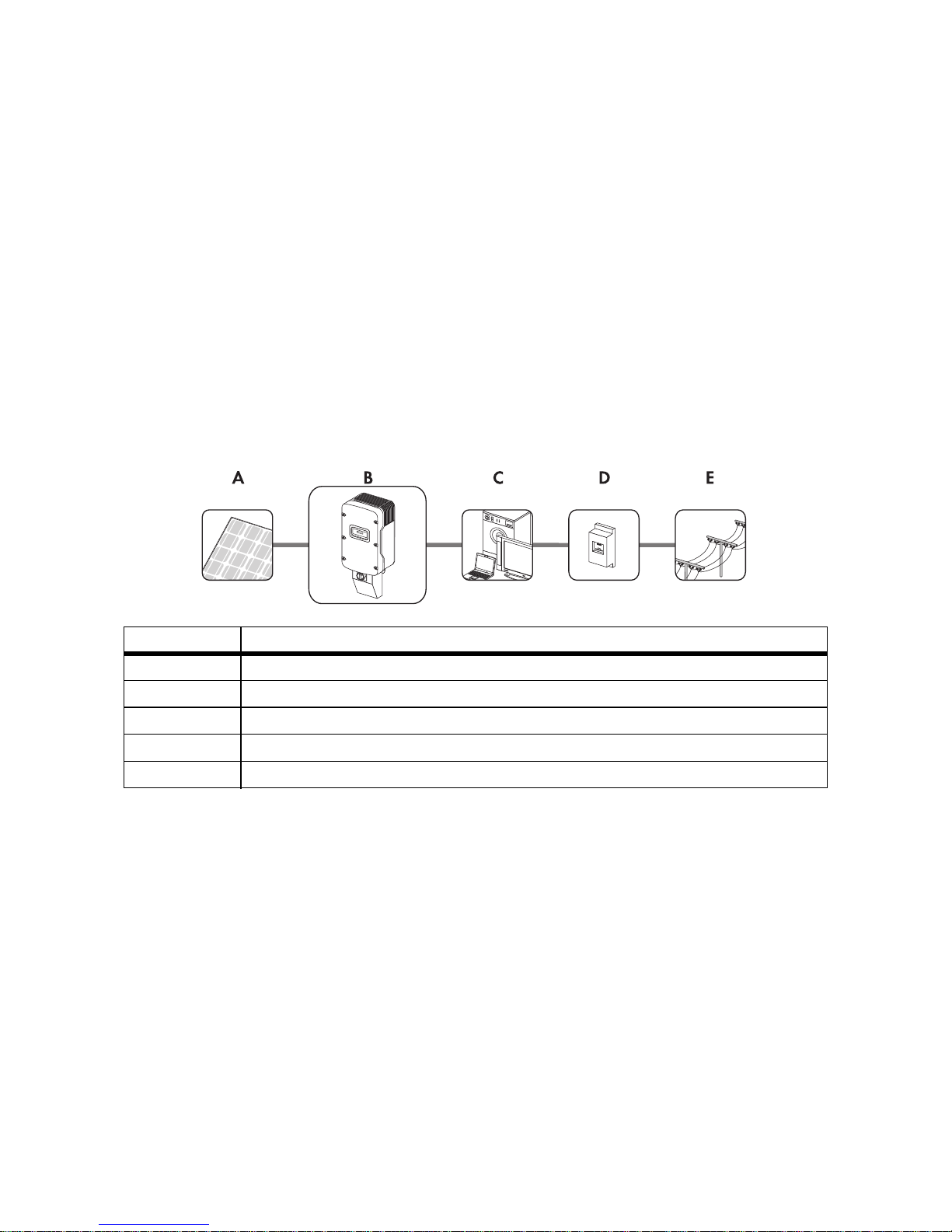
The Sunny Boy is a PV inverter which converts the DC current of the PV array to AC current and feeds
it into the power distribution grid. The Sunny Boy is suitable for use with fuel cells, small wind turbine
systems, and other DC current sources. The Sunny Boy takes the current from a DC source and
converts it into AC power for the power distribution grid. This power is then supplied to the local
consumers (C). Surplus energy is fed into the power distribution grid (E). Due to the power that is
consumed by the local devices, the amount of power required from the power distribution grid is
reduced. An energy surplus may even result in the energy meter (D) of your plant running backward.
This power may also be recorded as power credits by the electric utility company depending on the
interconnection agreement.
Principle of a PV Plant with a Sunny Boy
Ground Fault Detection and Interruption in the PV Array
All Sunny Boy inverters have a system for detecting ground fault errors in the PV array (GFDI)
according to the National Electrical Code® 690.5.
The PV array is operated in a grounded configuration. Depending on the plant type, the negative or
positive conductor of the PV array is connected to the grounding system in the Sunny Boy. According
to UL 1741, the GFDI protection is always active when sufficient DC voltage is present to switch on
the LC display in the Sunny Boy.
If a ground fault current larger than 1 A is flowing, the Sunny Boy switches off and displays the
interference. After the ground fault has been located and eliminated, the ground fault interference
must be cleared manually. Following this, the Sunny Boy resumes operation.
Position Description
A PV array
B Sunny Boy with DC disconnect
C Local consumers
D Energy meter
E Power distribution grid

SMA America, LLC Safety
SB50US-80US-IA-en-36 SB50US-80US-IA-en-36 13
Arc Fault Circuit Interrupter AFCI
Only the following Sunny Boy types are equipped with an automatic arc fault circuit interrupter
(AFCI):
• SB 5000US-12
• SB 6000US-12
• SB 7000US-12
• SB 8000US-12
Edition 2011 of the National Electrical Code
®,
Section 690.11, requires that all PV plants attached
to a building are fitted with a means of detecting and interrupting serial electric arcs (AFCI) on the PV
side.
An electric arc with a power of 300 W or greater must be interrupted by the AFCI in the time specified
by UL 1699B. A triggered AFCI may only be reset manually.
The arc fault circuit interrupter (AFCI) can be deactivated in the "Electrically qualified person" mode
via the communication device if this function is not desired.
Anti-Islanding Protection
A stand-alone grid is a status. It occurs when the power distribution grid is switched off and the Sunny
Boy is in operation. For this to happen, the remaining load must be resonant at 60 Hz and exactly
match the power of the Sunny Boy. Although the appearance of these conditions is extremely unlikely,
the Sunny Boy has an active safety algorithm to protect against islanding. The effect of this is that, in
the event of the power distribution grid being switched off, the PV plant does not supply any power
to a symmetrical load that is resonant at 60 Hz. In addition, the Sunny Boy regularly feeds leading
and lagging reactive currents into the power distribution grid. This procedure is checked by the
certification body in order to destabilize and switch off a stand-alone grid status.
Operating Temperature
The Sunny Boy delivers full performance in ambient temperatures up to +113 °F (+45 °C). Due to
the fan cooling, this level of performance can be achieved in closed rooms. The Sunny Boy does
remain operational above +113 °F (+45 °C), but it reduces the level of performance so as to protect
the internal component parts from overheating.

Safety SMA America, LLC
14 SB50US-80US-IA-en-36 Installation Manual
Interconnection Code Compliance
The Sunny Boy has been checked by the certification body and certified according to the guidelines
in UL 1741 Static Inverters and Charge Controllers for use in Photovoltaic Power Systems, IEEE 9292000 Recommended Practice for Utility Interface of Photovoltaic Systems, and IEEE 1547 Standard
for Interconnecting Distributed Resources with Electric Power Systems.
UL 1741 is the standard that is used for the Sunny Boy by the certification body in
order to certify that it complies with the regulations in National Electrical Code
®
and
IEEE 929-2000. IEEE 929-2000 states recommendations regarding the appropriate
equipment and functionality that is required to guarantee fault-free operation when the
power generation is connected to the power distribution grid.
The Sunny Boy is also certified according to Canadian Electrical Code® CSA C22.2
N0. 107.1-01 (General Use Power Supplies).
2.2 Safety Instructions
Prior to setting up and installing your PV plant, contact the on site grid operator or the
responsible authority.
DANGER
High voltages in the inverter
Electric shock when touching live components.
• Prior to performing any work on the inverter, disconnect the inverter from any voltage
sources.
• Only connect the inverters as described in this manual.
• Only electrically qualified persons may work on the inverter.
CAUTION
The inverter can become hot during operation
• Burn injuries may be possible when touching the enclosure.
• During operation, touch the enclosure lid only.
The Sunny Boy may down over due to inappropriate transport
Contusions or bone fractures due to the heavy weight of the Sunny Boy.
• Prior to transporting the Sunny Boy, take its weight of 148 lb. (67 kg) into
consideration.
• Use suitable lifting techniques for the transport.

SMA America, LLC Safety
SB50US-80US-IA-en-36 SB50US-80US-IA-en-36 15
2.3 Installation Overview
This section provides a brief overview of the installation process of a Sunny Boy.
Section 3: Unpacking and Inspection
This section provides instructions and information on unpacking the Sunny Boy and inspecting
shipping damage.
Section 4: AC Voltage Configuration
This section contains information on removing the cover, determining the position of the fundamental
component parts in the inverter and selecting the suitable voltage configuration for the installation.
Section 5: Mounting
This section provides guidelines to help you choose the best mounting location, recommendations for
achieving optimal performance, safety measures and warnings to prevent injuries and/or damage to
the device, and step-by-step instructions for mounting the Sunny Boy inverter.
Section 6: Wiring the Sunny Boy
This section contains guidelines for selecting the correct line cross-section, safety measures and
warnings to prevent injuries and/or damage to the device, and step-by-step instructions for connecting
the Sunny Boy to a PV array, to an electric circuit in the home, and to the power distribution grid.
Procedures are also included for connecting optional data communication cables.
Section 7: Commissioning
Commissioning comprises applying DC input power to the Sunny Boy, observing the LED and LCD
displays, and resolving any problems that occur.
Section 8: Displays and Messages
This section provides information on messages that may appear during commissioning and operation.
Section 9: Troubleshooting
This section provides information for troubleshooting and procedures for resolving problems that may
occur during commissioning and operation.
Section 10: Maintenance
This section contains the maintenance and cleaning of the Sunny Boy and safety measures and
warnings for preventing injuries and damage to the device.
Section 11: Technical Data
This section contains the technical data of the Sunny Boy, connection diagrams, and the correct
tightening torques for connecting the cables and screws to the Sunny Boy.
Unpacking and Inspection SMA America, LLC
16 SB50US-80US-IA-en-36 Installation Manual
3 Unpacking and Inspection
Check the delivery for completeness and any visible external damage. Contact your SMA specialty
retailer or SMA if the delivery is incomplete or you find any damage.
If it is necessary to send the Sunny Boy back, use the original packaging.
Contact information is provided in the "Contact" section, page 103.
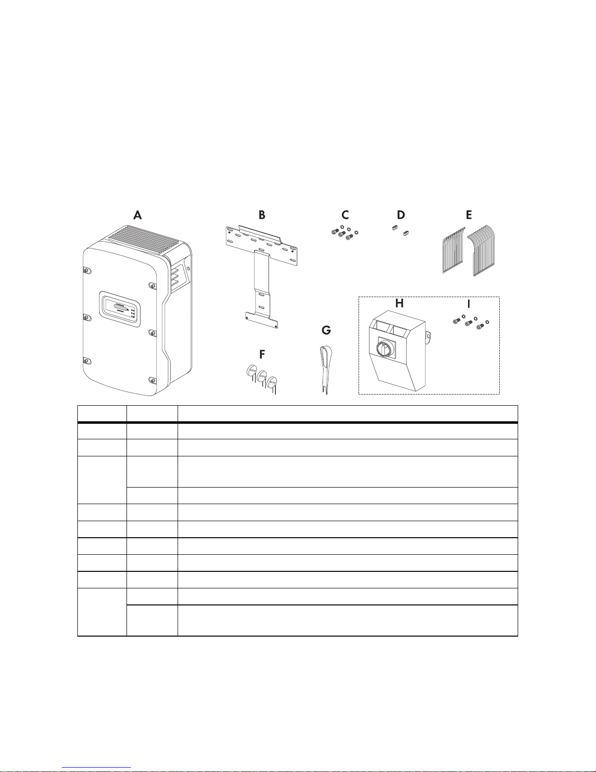
3.1 Scope of Delivery
* only SB 5000US-12/SB 6000US-12/SB 7000US-12/SB 8000US-12
Position Quantity Description
A1 Sunny Boy
B1 Wall mounting bracket
C 1 Replacement screw and replacement conical spring washers for connecting
the enclosure lid to the Sunny Boy.
2 Screws and washers for fastening the Sunny Boy to the wall mounting bracket
D 2 Spare jumpers for fan test
E 2 Handle covers (left and right)
F3DC varistors*
G 1 Insertion tool for DC varistors*
H1 DC Disconnect
I1Screw and washer for closing the DC Disconnect lid
2 Screws and washers for fastening the DC Disconnect to the wall-mounting
bracket
SMA America, LLC AC Voltage Configuration
SB50US-80US-IA-en-36 SB50US-80US-IA-en-36 17
4 AC Voltage Configuration
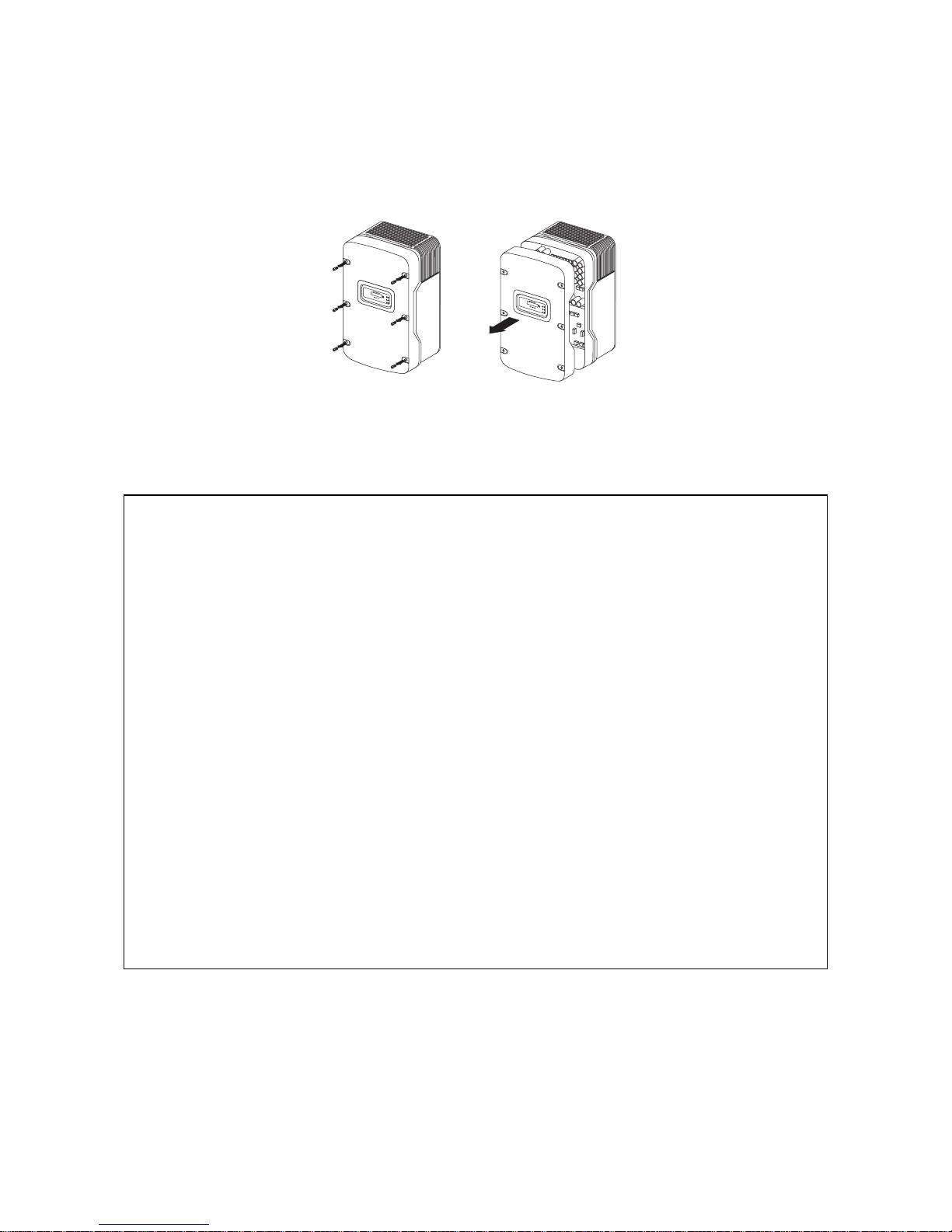
4.1 Opening the Sunny Boy
1. Remove the six screws and conical spring washers from the enclosure cover. Pull the cover
forward smoothly.
2. Put the cover, screws, and conical spring washers to one side so that they do not get in the way.
NOTICE
Ingress of moisture when mounting and installing the Sunny Boy
Potential damage to the Sunny Boy.
• For inserting the conduits into the enclosure and the DC Disconnect, only use ULcertified rainproof sleeves or waterproof sleeves that fulfill UL 514B.
• Do not open the Sunny Boy in the event of rain or a high level of humidity (> 95 %).
Damage to the seal of the enclosure lid during frost
When opening the Sunny Boy during frost, the seal of the enclosure lid can be damaged.
There may be an ingress of moisture damaging the Sunny Boy.
• Do not open the Sunny Boy when the outdoor temperature is below 23 °F ( − 5 °C).
Electrostatic discharges through touching component parts
Potential damage to the Sunny Boy.
• Ground yourself before touching any electronic component.
AC Voltage Configuration SMA America, LLC
18 SB50US-80US-IA-en-36 Installation Manual
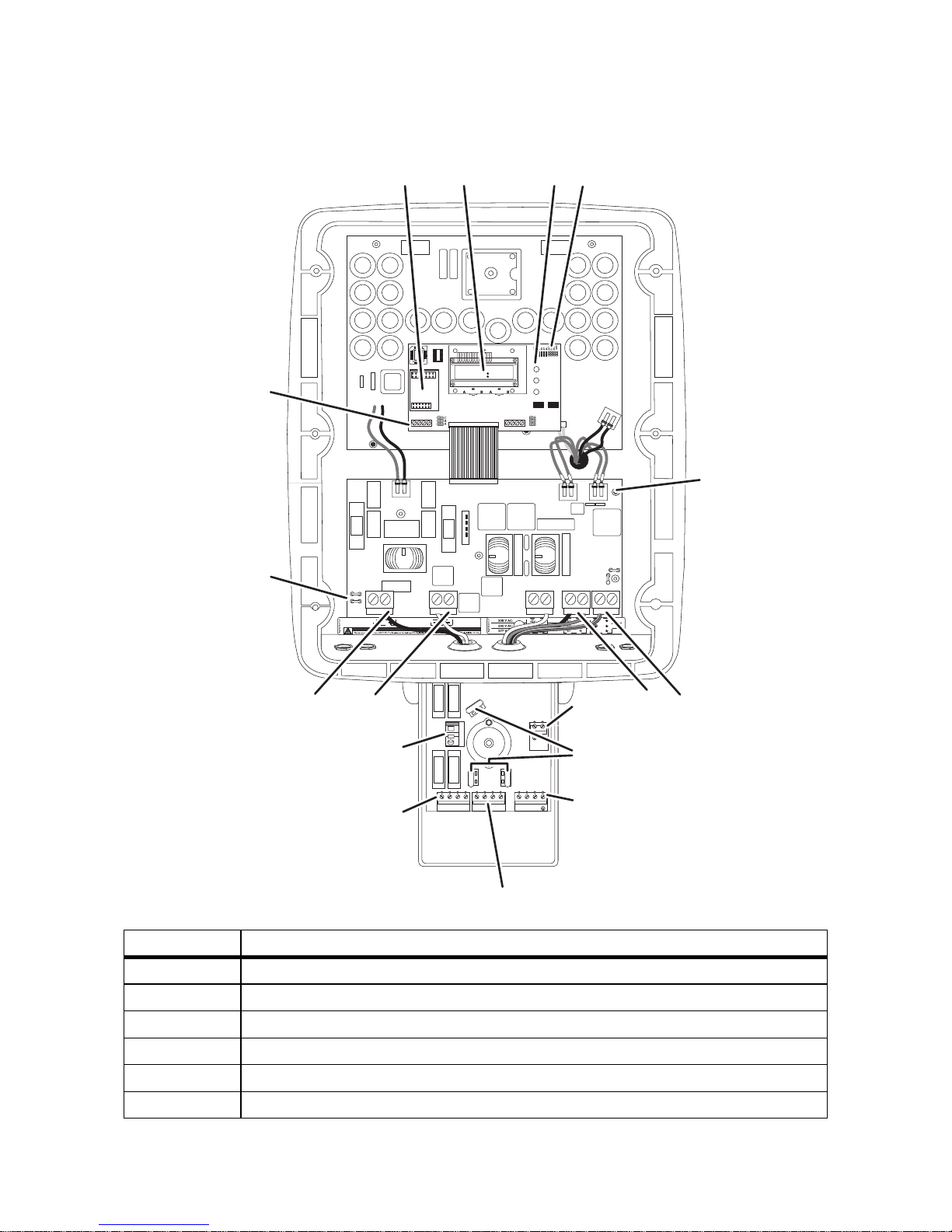
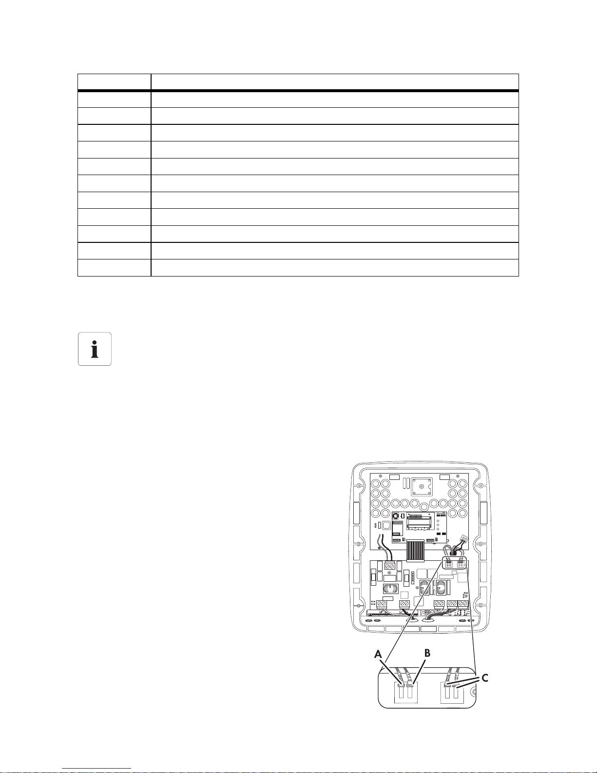
4.2 Locating Internal Component Parts
Position Description
A Sockets for optional communication Piggy-Back (RS485 or wireless)
BDisplay
C Status LEDs
D Jumpers for configuring the AC voltage and the fan test
E Terminal blocks for configuring the AC voltage
F Ground terminal (PE)
1234
UNGROUNDED GROUNDED
L1 L2 N
0
V
240
V
2
0
8
V
2
7
7
V
2357 AB+-
GROUNDING
ELECTRODE
CONDUCTOR
COMBINED
A
B
C
D
E
FG
H
I
M
N
OP
Q
R
L
K
SMA America, LLC AC Voltage Configuration
SB50US-80US-IA-en-36 SB50US-80US-IA-en-36 19
* only SB 5000US-12/SB 6000US-12/SB 7000US-12/SB 8000US-12
4.3 AC Voltage Configuration
The Sunny Boy is compatible with the following grid types:
• 208 V AC (not Sunny Boy 8000-US)
• 240 V AC
• 277 V AC
The Sunny Boy is configured ex works for connection to
the power distribution grid with a voltage of 240 V AC.
The Sunny Boy can be configured for other voltages.
4 cables are inserted into the enclosure via a cable
support sleeve. Each cable is labeled with its respective
voltage.
1. Connect the cable with the correct voltage to the
left terminal block (A).
2. To adjust the AC voltage, select the cable with the
correct voltage at the right terminal block (C).
Connect the selected cable to the left side of the left
terminal block (A).
3. Secure all screw terminals. If spring-type terminals
are available, close the levers of the terminals by
pressing down.
G Output AC conductor terminals (N, L1, and L2)
H Connecting terminal plate, PV grounding conductor, + DC grounding conductor
IDC varistor terminal with DC varistors*
K Output AC conductor terminals (L1, L2, N and PE)
L Terminal PV GROUNDED (PV array input)
M Terminal PV UNGROUNDED (PV array input)
N Combined terminal UNGROUNDED
OTerminal DC− (PV array input)
P Terminal DC+ (PV array input)
Q Flat male tab for grounding the cable shield for communication
R Terminal for optional communication (RS485)
The Sunny Boy 8000-US must not be connected to a 208 V grid.
Position Description
AC Voltage Configuration SMA America, LLC
20 SB50US-80US-IA-en-36 Installation Manual
Tightening torque of the screw terminals for the left terminal block:
4. Connect and fasten all cables not being used to the right terminal block (C). Tightening torques
of the screw terminals for the right terminal block (cables not being used):
Automatic Grid Voltage Detection
The Sunny Boy automatically detects the grid voltage that it must feed in. Depending on the voltage
and the phase angle between L1‑N and L2‑N, the inverter determines whether it is connected to a
208 V, 240 V, or 277 V grid. If the Sunny Boy is configured for the wrong grid voltage (for example,
the inverter was configured for 240 V and then connected to a 208 V grid), the Sunny Boy displays
an error message.
The table below contains the limiting values for voltage and frequency in the AC terminal:
If the power distribution grid uses a neutral conductor, the responsible authority can demand that a
neutral conductor be connected to the inverter.
To set the configuration jumpers, observe the procedure in 4.4 ”Jumper for System Configuration”
(page 22).
To connect a neutral conductor to the Sunny Boy, observe section 6.5.2 ”AC Connection in the DC
Disconnect” (page 42) or section "AC Connection in the DC Disconnect" on page 42.
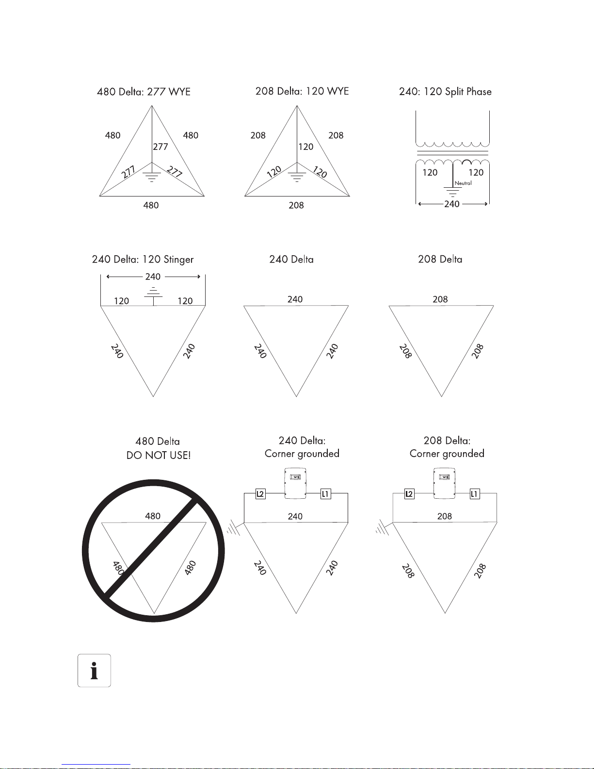
Configuration of Grid Voltage
The figure on the next page illustrates common grid forms. Note that it is not the phase relationship
that is important when connecting the Sunny Boy to the power distribution grid, but the voltage
compatibility.
Gray terminal blocks (Weidmüller) 18 in-lb. (2 Nm)
Green terminal blocks (Phoenix) 22 in-lb. (2.5 Nm)
Do not remove the cable in the left terminal block with the marking 0 V (B).
This always remains connected to the right side of the left terminal block.
Gray terminal blocks (Weidmüller) 11 in-lb. (1.2 Nm)
Green terminal blocks (Phoenix) 15 in-lb. (1.7 Nm)
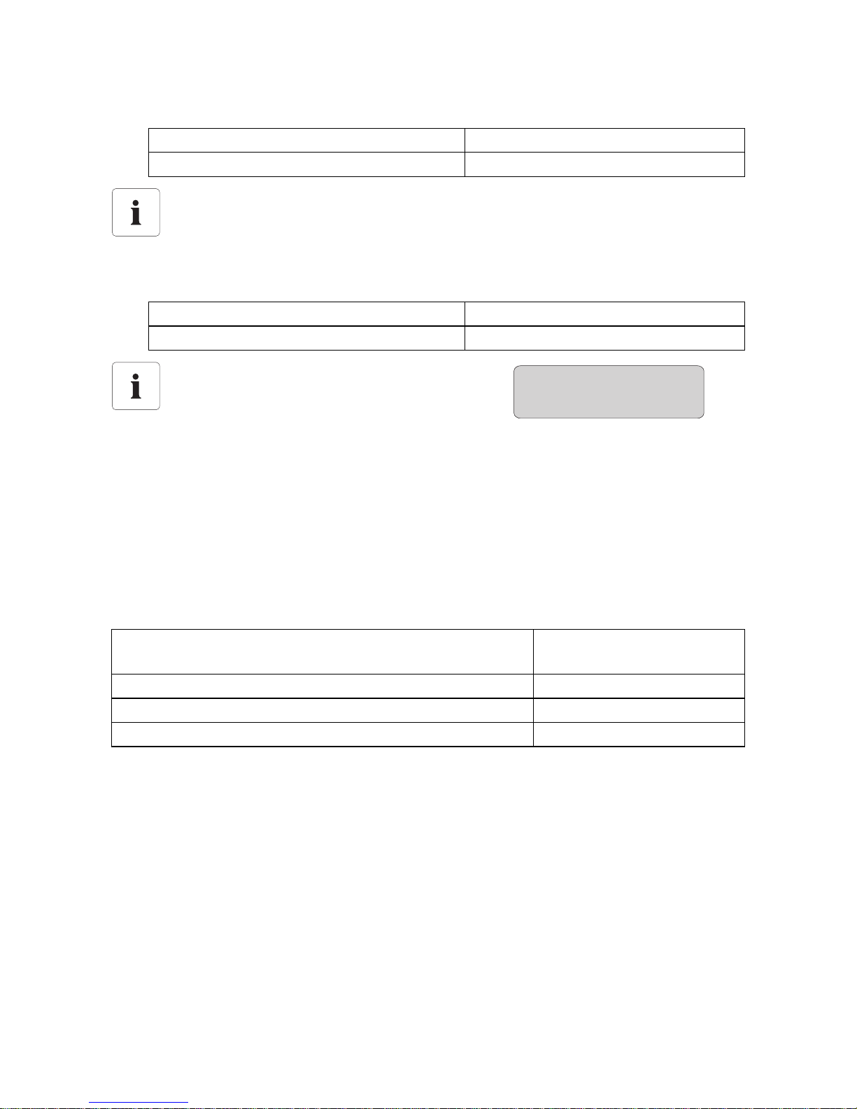
If the Sunny Boy is configured for the wrong
input voltage, this error message appears in
the display:
• Check if the configuration of the AC voltage is correct.
Voltage range for 208 V nominal value, phase-phase (not Sunny
Boy 8000-US)
183 V … 229 V
Voltage range for 240 V nominal value, phase-phase 211 V … 264 V
Voltage range for 277 V nominal value, phase-neutral conductor 244 V … 305 V
Frequency range 59.3 Hz … 60.5 Hz
Disturbance
XFMR
SMA America, LLC AC Voltage Configuration
SB50US-80US-IA-en-36 SB50US-80US-IA-en-36 21
*The Sunny Boy 8000-US must not be connected to a 208 V grid.
When using grounded 240 V or 208 V Delta grids:
• Connect terminal L2 to the grounded phase.
*
*
*
AC Voltage Configuration SMA America, LLC
22 SB50US-80US-IA-en-36 Installation Manual
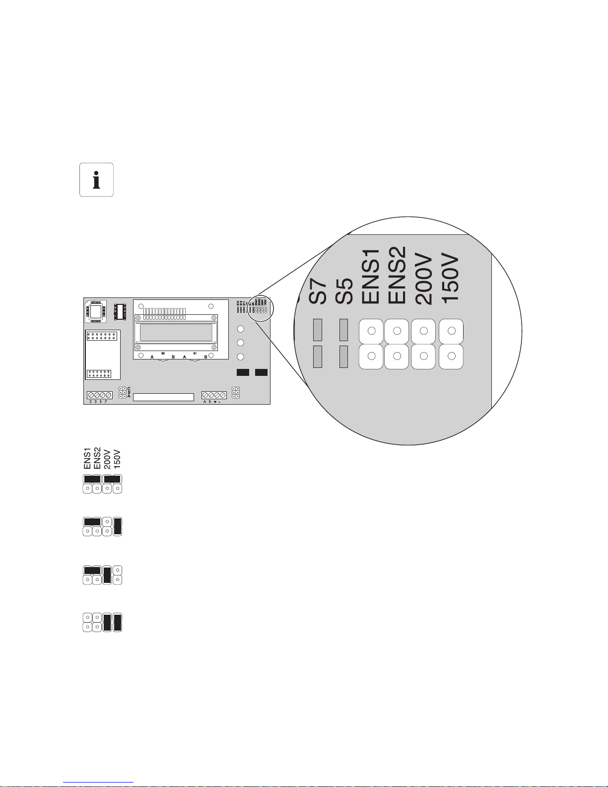
4.4 Jumper for System Configuration
By setting the jumper, you configure the Sunny Boy for different grid topologies. This means that
operation in system configurations without neutral conductors, such as 208 V and 240 V Delta, is
possible. The following figure provides an overview of the standard settings, the settings for grids
without neutral conductors, and the settings for the fan test.
* The Sunny Boy 8000-US must not be connected to a 208 V grid.
In the event of frost, the fan cannot be inspected
The fans are not activated under 32 °F (0 °C).
208V with neutral conductor*240 V with neutral conductor
or 277 V
208 V Delta, without neutral conductor or *
208 V Delta, grounded *
240 V Delta, without neutral conductor or
240 V Delta, grounded
Fan test
SMA America, LLC AC Voltage Configuration
SB50US-80US-IA-en-36 SB50US-80US-IA-en-36 23
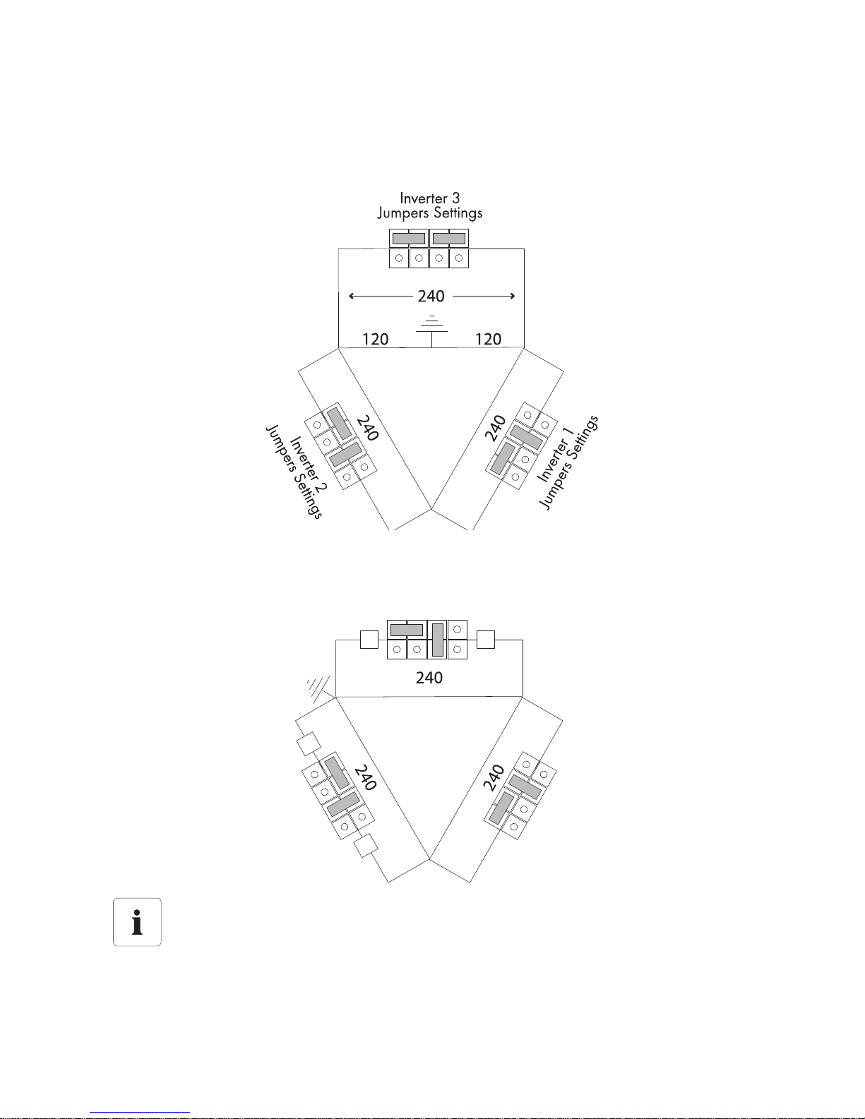
The following figures display the correct arrangement of the jumpers for the 240 V Delta system
configuration: Note the order in which the inverters are connected to the phases.
Configuration Examples for Jumpers with 240 V Delta, 120 V Stinger
Configuration Examples for Jumpers with 240 V Delta, Grounded
When using grounded 240 V or 208 V Delta grids
• Connect terminal L2 to the grounded phase.
L2 L1
L2
L1
Inverter 3
Jumpers Settings
Inverter 1
Jumpers Settings
Inverter 2
Jumpers Settings
Assembly SMA America, LLC
24 SB50US-80US-IA-en-36 Installation Manual
5 Assembly
5.1 Safety
DANGER
Danger to life due to fire or explosions.
With electrical devices, there is always a certain danger that a fire may break out.
• Do not install the inverter in the vicinity of combustible materials.
• Do not install the inverter in potentially explosive areas.
CAUTION
The Sunny Boy may fall down due to inappropriate mounting
Contusions or bone fractures due to the heavy weight of the Sunny Boy.
• When mounting the Sunny Boy, take its weight of 148 lb. (67 kg) into consideration.
• Use appropriate mounting material for the mounting location of the inverter:
– For mounting on plasterboard, do not use hollow wall anchors or toggle bolts.
– Wooden supporting posts must be present behind the installation points on
plasterboard.
• Use suitable lifting technique when mounting.
The inverter can become hot during operation
Burn injuries may be possible when touching the enclosure.
• Install the inverter in such a way that it cannot be touched accidentally.
SMA America, LLC Assembly
SB50US-80US-IA-en-36 SB50US-80US-IA-en-36 25
5.2 Requirements for the Mounting Location
Observe the following conditions during installation:
• The installation method and mounting location must be suitable for the weight and dimensions
of the Sunny Boy (see section 11 ”Technical Data” (page 91)).
• Note the dimensions of the DC disconnect (Page 32).
• Mount the inverter on a stable surface.
• The mounting location must be accessible at all times.
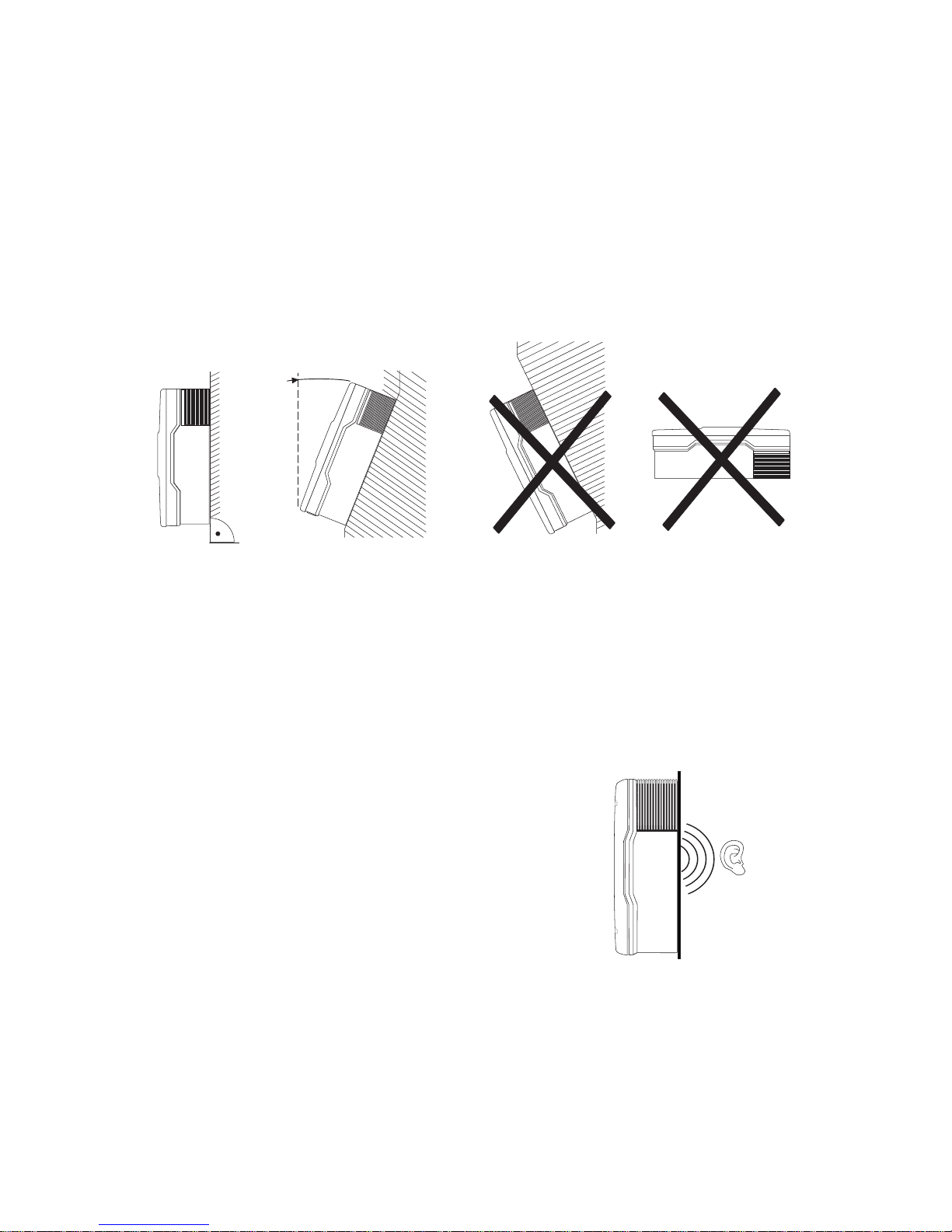
• Mount vertically or tilted backward at max. 45°.
• The connection area must point downward.
• Do not install the inverter tilting forward.
• Do not install the inverter horizontally.
• Install the inverter at eye level in order to be able to read out the operating state at any time.
• The ambient temperature must be below +113 °F (+45 °C).
• Do not expose the inverter to direct sunlight.
• In the living area, do not install inverters on a
plasterboard wall or similar wall.
The Sunny Boy may emit noises when in use which
can be regarded as a nuisance.
max. 45°
Assembly SMA America, LLC
26 SB50US-80US-IA-en-36 Installation Manual
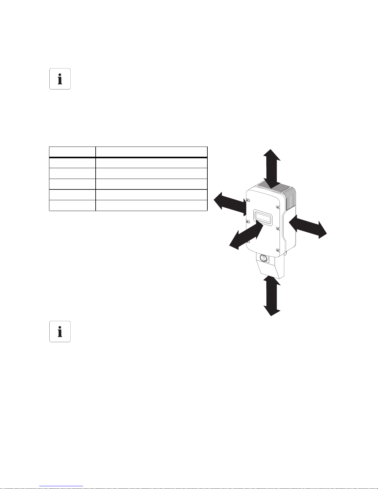
• Observe recommended clearances to walls, other inverters or other objects. As a result,
sufficient heat dissipation is ensured.
• If several inverters are mounted in areas with high ambient temperatures, increase the
clearances and ensure a sufficient fresh-air supply. Thus, you will prevent the inverter power
from being reduced due to too high temperatures.
Recommended clearances
The National Electrical Code® may stipulate greater clearances (see National Electrical
Code
®
, Section 110.26). Installations in Canada must be carried out in accordance with
the applicable Canadian standards.
Position Clearance
Top 12 in. (300 mm)
Bottom 36 in. (900 mm)
Left 12 in. (300 mm)
Right 12 in. (300 mm)
Front 2 in. (50 mm)
If the Sunny Boy is installed outdoors
• Observe minimum clearance to the ground of 36 in. (900 mm).
12 in.
12 in.
2 in.
12 in.
12 in.
SMA America, LLC Assembly
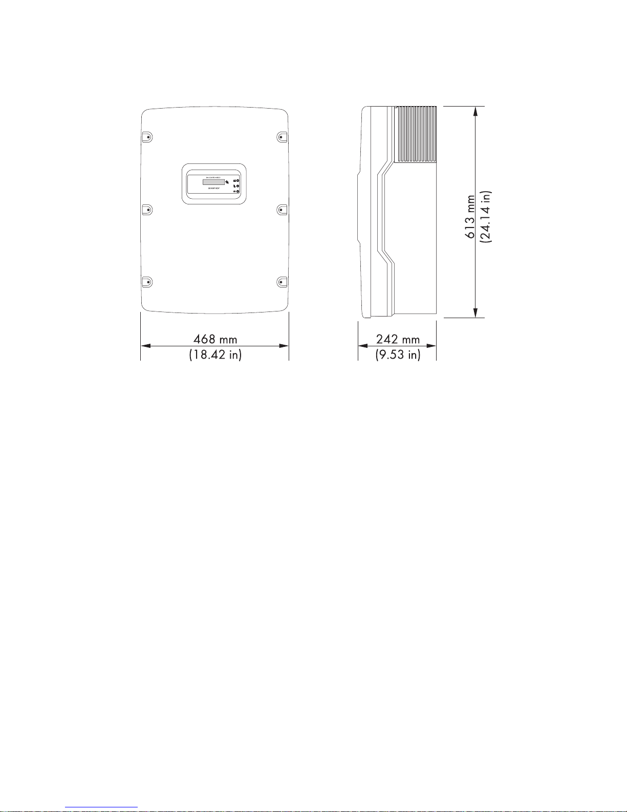
SB50US-80US-IA-en-36 SB50US-80US-IA-en-36 27
Dimensions of the Sunny Boy
5.3 Mounting with Wall Mounting Bracket
The Sunny Boy is supplied with a T-shaped wall mounting bracket that is suitable for most walls. The
wall must be vertical and stable enough to carry a weight of 145 lb. (67 kg) for a long period of time.
For the wall material, use suitable fastening elements no smaller than ¼ in.
Assembly SMA America, LLC
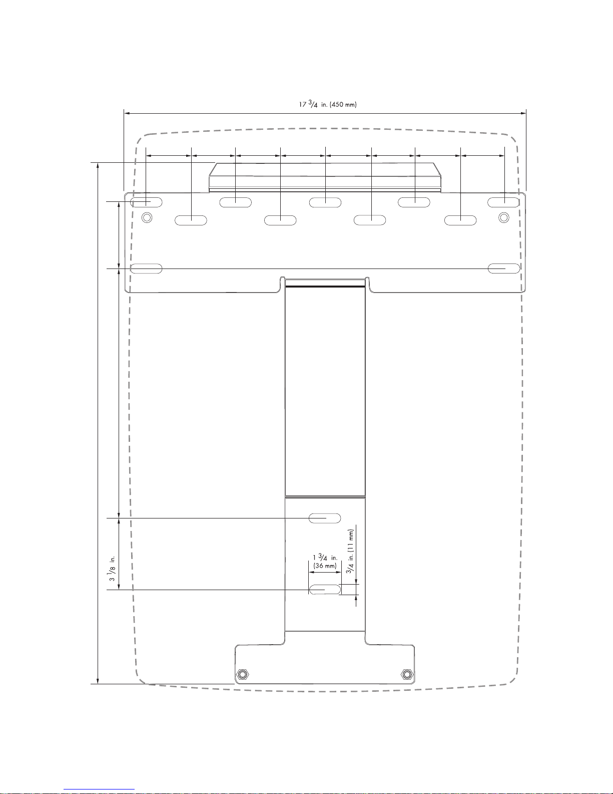
28 SB50US-80US-IA-en-36 Installation Manual
Dimensions of the Wall Mounting Bracket
2 in.
50 mm
2 in.
50 mm
2 in.
50 mm
2 in.
50 mm
2 in.
50 mm
2 in.
50 mm
2 in.
50 mm
2 in.
50 mm
23 in. (584 mm)
11 in. (280 mm)
(80 mm)
3 in. (74 mm)
SMA America, LLC Assembly
SB50US-80US-IA-en-36 SB50US-80US-IA-en-36 29
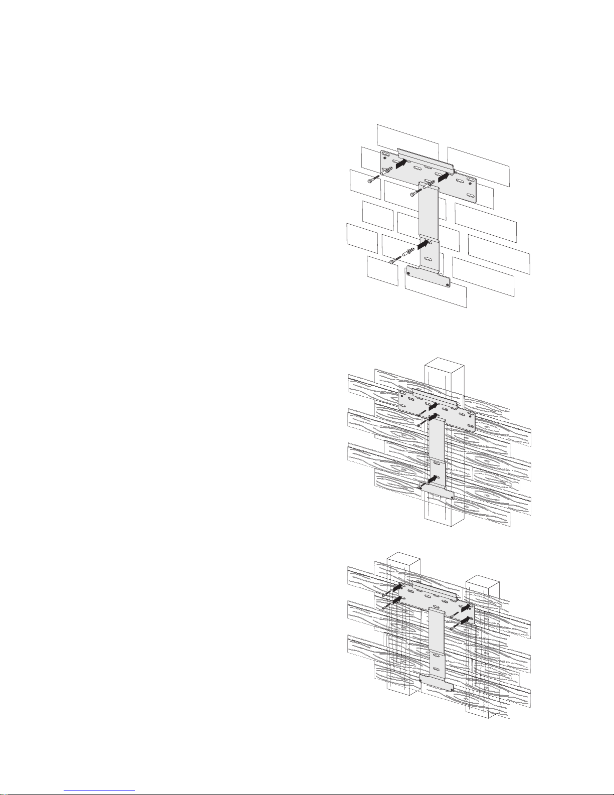
5.3.1 Possibilities for Mounting the Wall Mounting Bracket
Mounting on a Stone Wall
Secure the wall mounting bracket with at least 3 screws.
The position of the screws on the wall mounting bracket is
as follows:
• 1 screw on the upper left side.
• 1 screw on the upper right side.
• 1 screw below.
Mount the wall mounting bracket as described in section
5.3.2 ”Mounting the Wall Mounting Bracket”
(page 30).
Mounting on a Wooden Wall with a Stud or on a Pillar
Secure the wall mounting bracket with at least 3 screws.
The position of the screws on the wall mounting bracket is
as follows:
• 2 screws at the upper middle.
• 1 screw below.
Mount the wall mounting bracket as described in section
5.3.2 ”Mounting the Wall Mounting Bracket”
(page 30).
Mounting on a Wooden Wall with Two Studs
Secure the wall mounting bracket with at least 4 screws.
The position of the screws on the wall mounting bracket is
as follows:
• 2 screws on the upper left side.
• 2 screws on the upper right side.
Use the four outer mounting holes on the left and right
sides of the wall mounting bracket.
Mount the wall mounting bracket as described in section
5.3.2 ”Mounting the Wall Mounting Bracket”
(page 30).
Assembly SMA America, LLC
30 SB50US-80US-IA-en-36 Installation Manual
5.3.2 Mounting the Wall Mounting Bracket
1. Position the wall mounting bracket at the installation location. If possible, select eye level.
2. Align the wall mounting bracket with a spirit level. The bottom end of the wall mounting bracket
reaches approximately to the bottom corner of the inverter.
3. Use the wall mounting bracket as a template. Mark at least 3 holes in the horizontal or vertical
position of the wall mounting bracket (see section 5.3.1 ”Possibilities for Mounting the Wall
Mounting Bracket” (page 29)).
4. Remove the mounting bracket and drill the holes at the markings.
5. Insert the screws into the bore holes through the holes in the wall mounting bracket.
6. Tighten the screws clockwise until the wall mounting bracket hangs securely on the wall.
5.4 Mounting the DC Disconnect
Inserting the DC varistors
WARNING
Electric shock due to damaged electric cables
Electric cables may be located behind the installation points which can be damaged when
mounting the inverter.
• Ensure that no electric cables are located behind the installation points.
Information for the installation
The diameter of the bore holes must correspond to the fastening elements that you use for
mounting the inverter.
Mounting on a concrete wall:
• The hole diameter must be the same as the outer diameter of the screw anchors.
• Insert suitable screw anchors into the bore holes.
Mounting on a wall with wooden studs:
• The hole diameter must correspond to the screw diameter used. The screws should
be stainless steel. The diameter of the screws must correspond to the diameter of the
holes in the wall mounting bracket. The screws must be long enough to reach a depth
in the wall of 1
1
⁄2in.
The supplied DC varistors must only be used for the following inverter types:
SB 5000TLUS-12/SB 6000US-12/SB 7000US-12/SB 8000US-12.
 Loading...