

SMA SUNNY BOY 6.0-US, SUNNY BOY 3.8-US, SUNNY BOY 5.0-US, SB3.8-1SP-US-40, SB3.0-1SP-US-40 Installation Manual
...
SUNNY BOY
SUNNY BOY 3.0-US / 3.8-US / 5.0-US /
6.0-US / 7.0-US / 7.7-US
SB3.0-1SP-US-40 / SB3.8-1SP-US-40 / SB5.0-1SP-US-40 /
SB6.0-1SP-US-40 / SB7.0-1SP-US-40 / SB7.7-1SP-US-40
ENGLISH
FRANÇAIS
Installation Manual
Instructions d’installation
eManual
ESPAÑOL
SBxx-1SP-US-40-IA-xx-15 | 98-137600.05 | Version 1.5
Instrucciones de instalación

ENGLISH
Legal Provisions
SMA Solar Technology AG
Legal Provisions
The information contained in these documents is the property of SMA Solar Technology AG. No
part of this document may be reproduced, stored in a retrieval system, or transmitted, in any form or
by any means, be it electronic, mechanical, photographic, magnetic or otherwise, without the prior
written permission of SMA Solar Technology AG. Internal reproduction used solely for the purpose
of product evaluation or other proper use is allowed and does not require prior approval.
SMA Solar Technology AG makes no representations or warranties, express or implied, with
respect to this documentation or any of the equipment and/or software it may describe, including
(with no limitation) any implied warranties of utility, merchantability, or fitness for any particular
purpose. All such representations or warranties are expressly disclaimed. Neither SMA Solar
Technology AG nor its distributors or dealers shall be liable for any indirect, incidental, or
consequential damages under any circumstances.
The exclusion of implied warranties may not apply in all cases under some statutes, and thus the
above exclusion may not apply.
Specifications are subject to change without notice. Every attempt has been made to make this
document complete, accurate and up-to-date. Readers are cautioned, however, that product
improvements and field usage experience may cause SMA Solar Technology AG to make changes
to these specifications without advance notice, or per contract provisions in those cases where a
supply agreement requires advance notice. SMA Solar Technology AG shall not be responsible for
any damages, including indirect, incidental or consequential damages, caused by reliance on the
material presented, including, but not limited to, omissions, typographical errors, arithmetical errors
or listing errors in the content material.
SMA Warranty
You can download the current warranty conditions from the Internet at www.SMA-Solar.com.
Software licenses
The licenses for the used software modules can be called up on the user interface of the product.
Trademarks
All trademarks are recognized, even if not explicitly identified as such. Missing designations do not
mean that a product or brand is not a registered trademark.
SMA Solar Technology AG
Sonnenallee 1
34266 Niestetal
Germany
Tel. +49 561 9522-0
Fax +49 561 9522-100
www.SMA.de
Email: info@SMA.de
Status: 2/5/2019
Copyright © 2019 SMA Solar Technology AG. All rights reserved.
Installation ManualSBxx-1SP-US-40-IA-xx-152

SMA Solar Technology AG
Table of Contents
Table of Contents
1 Information on this Document................................................. 5
1.1 Validity........................................................................................................................ 5
1.2 Target Group.............................................................................................................. 5
1.3 Content and Structure of this Document ................................................................... 5
1.4 Levels of warning messages...................................................................................... 5
1.5 Symbols in the Document .......................................................................................... 6
1.6 Typographies in the document.................................................................................. 6
1.7 Designation in the document..................................................................................... 6
1.8 Additional Information ............................................................................................... 6
2 Safety ........................................................................................ 8
2.1 Intended Use .............................................................................................................. 8
2.2 IMPORTANT SAFETY INSTRUCTIONS.................................................................... 9
3 Scope of Delivery..................................................................... 13
4 Product Overview .................................................................... 14
4.1 Product Description .................................................................................................... 14
4.2 Symbols on the Product ............................................................................................. 15
4.3 Interfaces and Functions ............................................................................................ 16
4.4 LED Signals................................................................................................................. 20
5 Mounting................................................................................... 22
5.1 Requirements for Mounting ....................................................................................... 22
5.2 Mounting the Inverter................................................................................................. 26
ENGLISH
6 Electrical Connection................................................................ 29
6.1 Overview of the Connection Area ............................................................................ 29
6.1.1 View from Below..................................................................................... 29
6.1.2 Interior View............................................................................................ 30
6.2 AC Connection........................................................................................................... 31
6.2.1 Requirements for the AC Connection.................................................... 31
6.2.2 Connecting the Inverter to the Utility Grid ............................................ 32
6.3 Connecting the Network Cables............................................................................... 35
6.4 Connecting the Multifunction Relay .......................................................................... 36
6.4.1 Procedure for connecting the multifunction relay ................................. 36
6.4.2 Operating Modes of the Multifunction Relay....................................... 36
6.4.3 Connection Options ............................................................................... 37
6.4.4 Connection to the Multifunction Relay .................................................. 40
6.5 Connecting the Switch and Outlet for Secure Power Supply Operation ............... 42
Installation Manual SBxx-1SP-US-40-IA-xx-15 3

ENGLISH
Table of Contents
6.6 DC Connection........................................................................................................... 46
6.6.1 Requirements for the DC Connection.................................................... 46
6.6.2 Connecting the PV Array........................................................................ 47
SMA Solar Technology AG
7 Commissioning ......................................................................... 51
7.1 Commissioning Procedure ......................................................................................... 51
7.2 Commissioning the Inverter........................................................................................ 51
7.3 Establishing a connection to the user interface ........................................................ 53
7.3.1 Establishing a Direct Connection via Ethernet ...................................... 53
7.3.2 Establishing a direct connection via WLAN ......................................... 53
7.3.3 Establishing a Connection via Ethernet in the local network ............... 55
7.3.4 Establishing a Connection via WLAN in the Local Network ............... 56
7.4 Logging Into the User Interface................................................................................. 57
7.5 Selecting a configuration option ............................................................................... 58
8 Disconnecting the Inverter from Voltage Sources................. 61
9 Decommissioning the Inverter................................................. 63
10 Technical Data .......................................................................... 65
10.1 DC/AC ....................................................................................................................... 65
10.1.1 Sunny Boy 3.0-US / 3.8-US / 5.0-US .................................................. 65
10.1.2 Sunny Boy 6.0-US / 7.0-US / 7.7-US .................................................. 67
10.2 AC Output, Secure Power Supply Operation.......................................................... 69
10.3 Multifunction Relay..................................................................................................... 69
10.4 Triggering Thresholds and Tripping Time.................................................................. 70
10.5 General Data ............................................................................................................. 70
10.6 Fan (only with Sunny Boy 7.0-US / 7.7-US)............................................................ 72
10.7 Protective Devices ...................................................................................................... 72
10.8 Torques....................................................................................................................... 72
10.9 Data Storage Capacity.............................................................................................. 73
11 Compliance Information.......................................................... 74
12 Contact ...................................................................................... 75
Installation ManualSBxx-1SP-US-40-IA-xx-154
SMA Solar Technology AG
1 Information on this Document
1 Information on this Document
1.1 Validity
This document is valid for:
• SB3.0-1SP-US-40 (SunnyBoy 3.0-US) from firmware version ≥ 2.04.88.R
• SB3.8-1SP-US-40 (SunnyBoy 3.8-US) from firmware version ≥ 2.04.88.R
• SB5.0-1SP-US-40 (SunnyBoy 5.0-US) from firmware version ≥ 2.04.88.R
• SB6.0-1SP-US-40 (Sunny Boy 6.0-US) from firmware version ≥ 2.04.88.R
• SB7.0-1SP-US-40 (SunnyBoy 7.0-US) from firmware version ≥ 2.04.88.R
• SB7.7-1SP-US-40 (SunnyBoy 7.7-US) from firmware version ≥ 2.04.88.R
1.2 Target Group
The tasks described in this document must only be performed by qualified persons. Qualified
persons must have the following skills:
• Knowledge of how an inverter works and is operated
• Training in how to deal with the dangers and risks associated with installing, repairing and
using electrical devices and installations
• Training in the installation and commissioning of electrical devices and installations
• Knowledge of all applicable laws, standards and directives
• Knowledge of and compliance with this document and all safety information
1.3 Content and Structure of this Document
This document describes the installation, commissioning and decommissioning of the product.
You will find the latest version of this document and further information on the product in PDF format
at www.SMA-Solar.com.
The latest version of this document and the manual for operating the user interface as well as
information on configuration and troubleshooting of the product are to be found in PDF format at
www.SMA-Solar.com.
Illustrations in this document are reduced to the essential information and may deviate from the real
product.
ENGLISH
1.4 Levels of warning messages
The following levels of warning messages may occur when handling the product.
DANGER
Indicates a hazardous situation which, if not avoided, will result in death or serious injury.
WARNING
Indicates a hazardous situation which, if not avoided, could result in death or serious injury.
Installation Manual SBxx-1SP-US-40-IA-xx-15 5
☐
☑
✖
ENGLISH
1 Information on this Document
SMA Solar Technology AG
CAUTION
Indicates a hazardous situation which, if not avoided, could result in minor or moderate injury.
NOTICE
Indicates a situation which, if not avoided, can result in property damage.
1.5 Symbols in the Document
Symbol Explanation
Information that is important for a specific topic or goal, but is not safety-relevant
Indicates a requirement for meeting a specific goal
Desired result
A problem that might occur
Example
1.6 Typographies in the document
Typography Use Example
bold
>
[Button]
[Key]
• Messages
• Terminals
• Elements on a user interface
• Elements to be selected
• Elements to be entered
• Connects several elements to be
selected
• Button or key to be selected or
pressed
• Connect the insulated
conductors to the terminals
X703:1 to X703:6.
• Enter 10 in the field
Minutes.
• Select Settings > Date.
• Select [Enter].
1.7 Designation in the document
Complete designation Designation in this document
SunnyBoy Inverter, product
1.8 Additional Information
For more information, please go to www.SMA-Solar.com.
Installation ManualSBxx-1SP-US-40-IA-xx-156
SMA Solar Technology AG
1 Information on this Document
Title and information content Type of information
Operation, configuration and troubleshooting User Manual
"Application for SMAGridGuard Code" Form
"PUBLIC CYBER SECURITY - Guidelines for a Secure PV System
Technical information
Communication"
"Efficiency and Derating"
Technical Information
Efficiency and derating behavior of the SMA inverters
"Grid Support Utility Interactive Inverters"
Technical Information
Information about how to activate and to set the grid supporting features according to UL1741SA
"Parameters and Measured Values"
Technical Information
Overview of all inverter operating parameters and their configuration options
"SMA and SunSpec Modbus® Interface"
Technical Information
Information on the Modbus interface
"Modbus® parameters and measured values"
Technical Information
Device-specific register HTML file
"SMAModbus® Interface"
Technical Information
Information on the commissioning and configuration of the SMA
Modbus interface
ENGLISH
Installation Manual SBxx-1SP-US-40-IA-xx-15 7

ENGLISH
2 Safety
SMA Solar Technology AG
2 Safety
2.1 Intended Use
The Sunny Boy is a transformerless PV inverter which converts the direct current of the PV array to
grid-compliant alternating current and feeds it into the utility grid.
The product is suitable for indoor and outdoor use.
The product must only be operated with PV arrays (PV modules and cabling) that are approved by
the electrical standards applicable on-site and the NationalElectricalCode® ANSI/NFPA 70 or
the CanadianElectricalCode® CSA C22.1.
No galvanic isolation
The product is not equipped with a transformer and therefore has no galvanic isolation.
• Do not operate grounded PV modules together with the product. If grounded PV modules
are connected to the product, an event will occur which will appear on the product
display. The event will also be displayed, along with the associated message, in the event
list on the user interface of the product.
• Only ground the mounting frames of the PV modules.
• The neutral conductor of the AC output is not bonded to ground within the product.
• The neutral conductor of the AC output for secure power supply operation is bonded to
ground within the product.
PV modules with a high capacity to ground may only be used if their coupling capacity does not
exceed 2.5μF.
To protect the PV system against excessive reverse currents under fault conditions, a DC-side
overcurrent protective device must be connected in accordance with the National Electrical Code
to prevent any short-circuit currents that exceed the ampacity of the DC electric circuit or the
maximum series fuse rating of the PV modules. Typically, this requires string fusing where more than
two strings are combined in parallel. Where an overcurrent protection device is required, the
National Electrical Code® requires that both positive and negative conductors have overcurrent
protection for ungrounded PV modules.
All components must remain within their permitted operating ranges and their installation
requirements at all times.
The product is approved for the US and Canadian market.
Use this product only in accordance with the information provided in the enclosed documentation
and with the locally applicable laws, regulations, standards and directives. Any other application
may cause personal injury or property damage.
Alterations to the product, e.g. changes or modifications, are only permitted with the express written
permission of SMA Solar Technology AG. Unauthorized alterations will void guarantee and
warranty claims and in most cases terminate the operating license. SMA Solar Technology AG
shall not be held liable for any damage caused by such changes.
®
Installation ManualSBxx-1SP-US-40-IA-xx-158
SMA Solar Technology AG
Any use of the product other than that described in the Intended Use section does not qualify as the
intended use.
The enclosed documentation is an integral part of this product. Keep the documentation in a
convenient, dry place for future reference and observe all instructions contained therein.
This document does not replace and is not intended to replace any local, state, provincial, federal
or national laws, regulations or codes applicable to the installation, electrical safety and use of the
product. SMA Solar Technology AG assumes no responsibility for the compliance or noncompliance with such laws or codes in connection with the installation of the product.
The type label must remain permanently attached to the product.
2 Safety
2.2 IMPORTANT SAFETY INSTRUCTIONS
SAVE THESE INSTRUCTIONS
This section contains safety information that must be observed at all times when working on or with
the product.
The product has been designed and tested in accordance with international safety requirements. As
with all electrical or electronical devices, there are residual risks despite careful construction. To
prevent personal injury and property damage and to ensure long-term operation of the product,
read this section carefully and observe all safety information at all times.
DANGER
Danger to life due to electric shock when live components or DC conductors
are touched
When exposed to sunlight, the PV modules generate high DC voltage which is present in the DC
conductors. Touching live DC conductors results in death or lethal injuries due to electric shock.
• Disconnect the product from voltage sources and make sure it cannot be reconnected
before working on the device.
• Do not touch non-insulated parts or cables.
• Do not remove the terminal block with the connected DC conductors from the slot under
load.
• Wear suitable personal protective equipment for all work on the product.
ENGLISH
Installation Manual SBxx-1SP-US-40-IA-xx-15 9
ENGLISH
2 Safety
SMA Solar Technology AG
DANGER
Danger to life due to electric shock when touching live system components in
case of a ground fault
If a ground fault occurs, parts of the system may still be live. Touching live parts and cables
results in death or lethal injuries due to electric shock.
• Disconnect the product from voltage sources and make sure it cannot be reconnected
before working on the device.
• Touch the cables of the PV array on the insulation only.
• Do not touch any parts of the substructure or frame of the PV array.
• Do not connect PV strings with ground faults to the inverter.
• Ensure that no voltage is present and wait five minutes before touching any parts of the PV
system or the product.
DANGER
Danger to life due to electric shock in case of overvoltages and if surge
protection is missing
Overvoltages (e.g. in the event of a flash of lightning) can be further conducted into the building
and to other connected devices in the same network via the network cables or other data cables
if there is no surge protection. Touching live parts and cables results in death or lethal injuries due
to electric shock.
• Ensure that all devices in the same network are integrated in the existing overvoltage
protection.
• When laying the network cable outdoors, ensure that there is suitable surge protection at
the network cable transition from the product outdoors to the network inside the building.
• The Ethernet interface of the inverter is classified as "TNV-1" and offers protection against
overvoltages of up to 1.5kV.
WARNING
Danger to life due to fire or explosion
Despite careful construction, a fire or explosion may occur in electrical devices. Death or lethal
injuries due to fire or flying debris can result.
• Wear suitable personal protective equipment for all work on the product.
• Do not mount the product in areas containing highly flammable materials or gases.
• Do not mount the product in potentially explosive atmospheres.
• Ensure that unauthorized persons have no access to the product.
• In case of error, only carry out corrective measures specified by SMA Solar Technology AG
(for corrective measures see section "troubleshooting" in the detailed manual. If no
corrective measures are specified, do not perform any actions on the product. Contact the
Service.
Installation ManualSBxx-1SP-US-40-IA-xx-1510
SMA Solar Technology AG
2 Safety
CAUTION
Risk of burns from hot surfaces
The surface of the inverter can get very hot. Touching the surface can result in burns.
• Mount the inverter in such a way that it cannot be touched inadvertently.
• Do not touch hot surfaces.
• Wait 30 minutes for the surface to cool sufficiently.
• Observe the safety messages on the inverter.
CAUTION
Risk of injury due to weight of product
Injuries may result if the product is lifted incorrectly or dropped while being transported or when
attaching it to or removing it from the wall mounting bracket.
• Transport and lift the product carefully. Take the weight of the product into account.
• Wear suitable personal protective equipment for all work on the product.
NOTICE
Damage to the enclosure seal in subfreezing conditions
If you open the product or disconnect the PowerUnit and ConnectionUnit when temperatures
are below freezing, the enclosure seals can be damaged. Moisture can penetrate the product
and damage it.
• If a layer of ice has formed on the enclosure seal when temperatures are below freezing,
remove it prior to opening the product (e.g. by melting the ice with warm air). Observe the
applicable safety regulations.
• Do not disassemble the PowerUnit and ConnectionUnit unless the ambient temperature is
at least 0°C (32°F) and conditions are frost-free.
ENGLISH
NOTICE
Damage to the product due to sand, dust and moisture ingress
Sand, dust and moisture penetration can damage the product and impair its functionality.
• Only open the product if the humidity is within the thresholds and the environment is free of
sand and dust.
• Do not open the product during a dust storm or precipitation.
• Close tightly all enclosure openings.
• Only use listed rain-tight or liquid-tight conduit fittings to attach the conduits to the product.
NOTICE
Damage due to cleaning agents
The use of cleaning agents may cause damage to the product and its components.
• Clean the product and all its components only with a cloth moistened with clear water.
Installation Manual SBxx-1SP-US-40-IA-xx-15 11
ENGLISH
2 Safety
SMA Solar Technology AG
NOTICE
Damage to the inverter due to electrostatic discharge
Touching electronic components can cause damage to or destroy the inverter through
electrostatic discharge.
• Ground yourself before touching any component.
NOTICE
Destruction of the measuring device due to overvoltage
• Only use measuring devices with a DC input voltage range of 600V or higher.
Electrical installations (for North America)
All installations must conform with the laws, regulations, codes and standards applicable in the
jurisdiction of installation (e.g. National Electrical Code® ANSI/NFPA 70 or Canadian
Electrical Code® CSA-C22.1.).
• Before connecting the product to the utility grid, contact your local grid operator. The
electrical connection of the product must be carried out by qualified persons only.
• Ensure that the cables or conductors used for electrical connection are not damaged.
Installation ManualSBxx-1SP-US-40-IA-xx-1512
SMA Solar Technology AG
A B
TOP
(Name des Gerätes):
Bitte füllen Sie die folgenden Felder aus:
:
Typ:
Seriennummer:
Datum der Inbetriebnahme:
Anschrift:
Installationsbetrieb
T
yp:
Seriennummer:
Datum der Inbetriebnahme:
Anschrift:
Installationsbetrieb
Gewährleistungs- und Garantiebedingungen
SUNNY BO
Y
D
L1
L2
N
E F G
J M
L N
A+ B+ C+ A− B− C−
H I K L
C
3 Scope of Delivery
3 Scope of Delivery
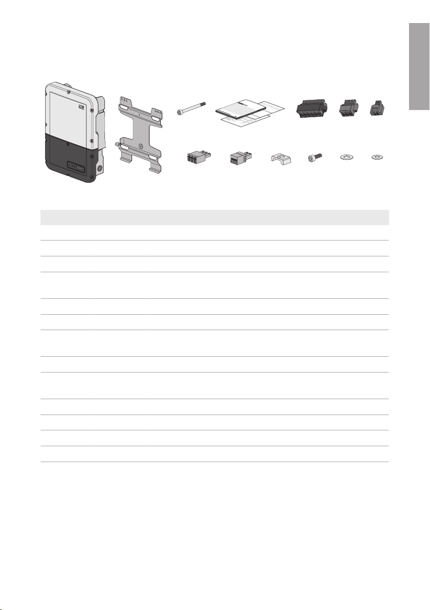
Figure 1 : Components included in the scope of delivery
Position Quantity Designation
A 1 Inverter
B 1 Wall mounting bracket
C 1 Cylindrical screw M5x60
D 1 Installation manual, production test report, supplementary sheet with
the default settings
E 1 Terminal block for the DC connection
F 1 Terminal block for the AC connection
G 1 Terminal block for connecting the outlet for secure power supply op-
eration
H 1 3-pole terminal block for the connection to the multifunction relay
I 1 2-pole terminal block for the switch connection for secure power
supply operation
J 5 Clamping bracket
K 5 Cylindrical screw M5x16
L 5 Washer M5
M 5 Spring washer M5
ENGLISH
Installation Manual SBxx-1SP-US-40-IA-xx-15 13
SUNNY BO
Y
G
K
I
H
J
SUNNY BO
Y
B
E
C
A
D
F
ENGLISH
4 Product Overview
4 Product Overview
4.1 Product Description
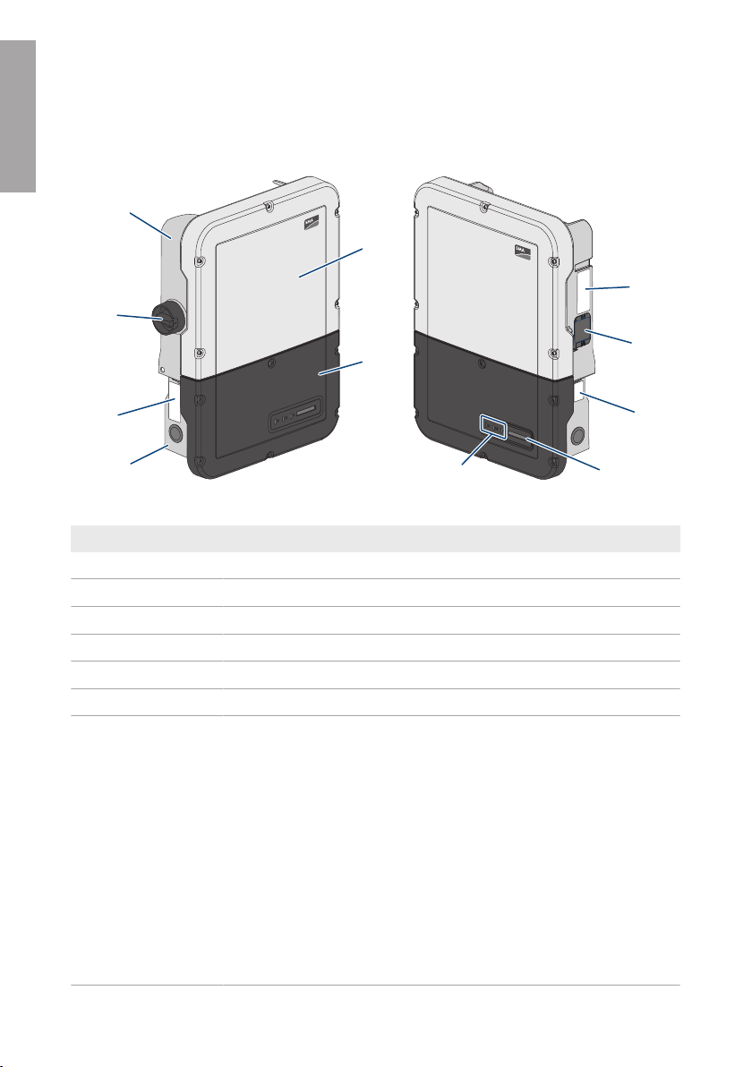
Figure 2 : Design of the inverter
Position Designation
A Power Unit
B Enclosure lid of the Power Unit
C Enclosure lid for the Connection Unit
D Connection Unit
E Warning label with compliance information
F DC load-break switch
G Type label
The type label clearly identifies the product. The type label must remain
permanently attached to the product. You will find the following information on the type label:
• Device type (Model)
• Serial number (Serial No. or S/N)
• Date of manufacture
• Identification key (PIC) for registration in Sunny Portal
• Registration ID (RID) for registration in Sunny Portal
• WLAN password (WPA2-PSK) for the direct connection to the user
• Device-specific characteristics
interface of the inverter via WLAN
SMA Solar Technology AG
Installation ManualSBxx-1SP-US-40-IA-xx-1514
SMA Solar Technology AG
Position Designation
H Fan (only with Sunny Boy 7.0 and 7.7)
I Additional type label
The additional type label must remain permanently attached to the product. You will find the following information on the additional type label:
• Identification key (PIC) for registration in Sunny Portal
• Registration ID (RID) for registration in Sunny Portal
• WLAN password (WPA2-PSK) for the direct connection to the user
interface of the inverter via WLAN
J Display
The display shows the current operating data and events or errors.
K LEDs
The LEDs indicate the operating state of the inverter.
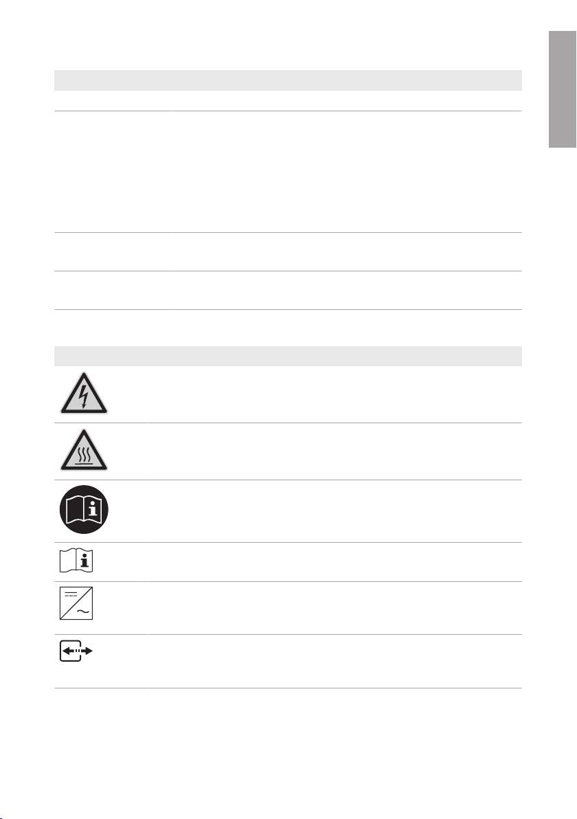
4.2 Symbols on the Product
Symbol Explanation
Beware of electrical voltage
The product operates at high voltages.
Beware of hot surface
The product can get hot during operation.
4 Product Overview
ENGLISH
Observe the documentation
Observe all documentation supplied with the product.
Observe the documentation
Together with the red LED, this symbol indicates an error.
Inverter
Together with the green LED, this symbol indicates the operating state of the in-
verter.
Data transmission
Together with the blue LED, this symbol indicates the status of the network connection.
Installation Manual SBxx-1SP-US-40-IA-xx-15 15
ENGLISH
4 Product Overview
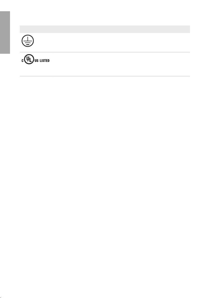
Symbol Explanation
Equipment Grounding Terminal
This symbol indicates the position for the connection of an equipment ground-
ing conductor.
UL1741 and CSA C22.2 No. 107.1 are the standards applied by Under-
writers Laboratories to the product to certify that it meets the requirements of
the National Electrical Code®, the Canadian Electrical Code® and
IEEE1547.
SMA Solar Technology AG
4.3 Interfaces and Functions
The inverter can be equipped or retrofitted with the following interfaces and functions:
User interface for monitoring and configuration
The product is equipped as standard with an integrated webserver, which provides a user interface
for configuring and monitoring the product. The product user interface can be called up via the web
browser if there is an existing connection to an end device (e.g. computer, tablet PC or
smartphone).
SMA Speedwire
The product is equipped with SMASpeedwire as standard. SMASpeedwire is a type of
communication based on the Ethernet standard. SMASpeedwire is designed for a data transfer
rate of 100Mbps and enables optimum communication between Speedwire devices within
systems.
Class 1 wiring methods are to be used for field wiring connection to the terminals of the
communication interface.
SMA Webconnect
The inverter is equipped with a Webconnect function as standard. The Webconnect function
enables direct data transmission between the inverter and SunnyPortal (online monitoring system
from SMA).
There are two SunnyPortal versions: the classical SunnyPortal (https://www.sunnyportal.com) and
the newly developed SunnyPortal powered by ennexOS (https://ennexOS.sunnyportal.com). Both
systems differ in their supported functions. With an existing user account, you can log into both
portals as well as into SunnyDesign (system planning software from SMA).
In a SunnyPortal system, up to four inverters with Webconnect function can be displayed together.
A communication product (e.g. SMADataManager) is required for systems with more than four
inverters.
The system must be registered in the classic SunnyPortal if the inverter is integrated into a local
network and connected to the Internet via this network. With this connection, you have the
possibility to view the data online in real time.
Installation ManualSBxx-1SP-US-40-IA-xx-1516

SMA Solar Technology AG
If the inverter is connected to the Internet via the cellular network, you must register the system in
SunnyPortal powered by ennexOS. The communication with the inverters is optimized with regard
to the data volume and availability of the inverter. No data can be viewed in real time. Note that
the inverter must be equipped with a firmware version ≥2.04.88.R for connection via the cellular
network.
4 Product Overview
WLAN
The product is equipped with a WLAN interface as standard. The inverter is delivered with the
WLAN interface activated as standard. If you do not want to use WLAN, you can deactivate the
WLAN interface.
In addition, the product has a WPS function. The WPS function is for automatically connecting the
product to a network (e.g. via router) and establish a direct connection between the product and
an end device.
Expanding the radio range in the WLAN network
In order to expand the radio range of the inverter in the WLAN network, you can install the
Antenna Extension Kit accessory set in the inverter.
Modbus
The product is equipped with a Modbus interface. The Modbus interface is deactivated by default
and must be configured as needed.
The Modbus interface of the supported SMA products is designed for industrial use – via SCADA
systems, for example – and has the following tasks:
• Remote query of measured values
• Remote setting of operating parameters
• Setpoint specifications for system control
ENGLISH
Module slots
The inverter is standard-equipped with two module slots. The module slots are located on the
communication assembly and allow additional modules to be connected (e.g. SMA Sensor
Module). The modules are available as accessories. The installation of two identical modules is not
permissible.
SMARS485Module
The inverter can be retrofitted with the SMA RS485 Module.
By installing the SMA RS485 Module, the inverter is able to communicate with the energy meter of
the SMARevenueGradeMeterKit.
Class 1 wiring methods are to be used for field wiring connection to the terminals of the
communication interface.
Antenna Extension Kit
Within the WLAN network, the Antenna Extension Kit enables the radio range of the inverter to be
upgraded (Information on assembly and connection see manual of the Antenna Extension Kit). The
Antenna Extension Kit can be retrofitted.
Installation Manual SBxx-1SP-US-40-IA-xx-15 17

ENGLISH
4 Product Overview
SMA Solar Technology AG
SMA Sensor Module
The SMA Sensor Module has different interfaces for connecting various sensors (i.e. temperature
sensor, irradiation sensor, anemometer or energy meter). The SMA Sensor Module converts the
signals of the connected sensors and transmits them to the inverter. The SMA Sensor Module can
be retrofitted.
SMA Cellular LTE Modem Kit
The inverter can be retrofitted with the SMA Cellular LTE Modem Kit.
The SMACellular LTE Modem Kit allows the direct data transmission between the inverter and the
internet portal SunnyPortal via the cellular network as an alternative to data transmission via
Ethernet or WLAN. In addition, the SMA Cellular LTE Modem Kit enables the communication
between the inverter and the energy meter.
The SMACellular LTE Modem Kit transmits up to four times a day a limited amount of data to
SunnyPortal. The standard term of the mobile data plan for the SMACellular LTE Modem Kit is five
years. All costs are covered within the term. No additional costs will be incurred. You have the
possibility to extend the term of the mobile data plan. For this purpose, contact SMA Solar
Technology AG. By using the SMACellular LTE Modem Kits, a local network connection is not
absolutely necessary. However, it is recommended to be able to view all information regarding the
system in SunnyPortal.
Energy meters in accordance with ANSI C12.20
The inverter can be retrofitted with the SMA Revenue Grade Meter Kit that in accordance with
ANSI C12.20 includes an energy meter.
The energy meter fulfills the accuracy class 0.5 in accordance with ANSI C12.20. The energy
meter is a so called PV production meter intended to measure the generated energy of the inverter.
The measured values of the energy meter can be used for billing purposes.
Grid Management Services
The inverter is a grid support interactive inverter.
The inverter was tested in accordance with the UL1741 SA (2016-09-07) to be compliant with the
source requirements documents of the states available at the time. For connecting the inverter to the
utility grid, no additional grid monitoring equipment is necessary. A description of the tested
functions and instructions on the activation and setting of functions can be found in the technical
information "Grid Support Utility Interactive Inverters" at www.SMA-Solar.com.
PVRapidShutdownSystemEquipment
The inverter is a PVRapidShutdownSystemEquipment and performs the function of voltage
reduction according to UL 1741 CRD PV Rapid Shutdown Systems 2015. When a rapid shutdown
is triggered by disconnecting the utility grid, the inverter discharges independently on the AC side to
≤30 V within 30 seconds.
If a disconnection device is used in addition between the inverter and the PV array that disconnects
the PV array in the case of a rapid shutdown, the inverter discharges independently on the DC side
to ≤30V within 30 seconds.
The electric discharge on the DC side is deactivated by default and must be activated manually
after commissioning of the inverter via the user interface.
Installation ManualSBxx-1SP-US-40-IA-xx-1518

SMA Solar Technology AG
NOTICE - The inverter's Rapid Shutdown function is initiated by disconnecting the inverter from the
AC grid voltage, for example, by opening the main PV system AC disconnect. The AC disconnect
that serves as the Rapid Shutdown initiation device must be readily accessible and clearly marked
in accordance with National Electrical Code®. The Rapid Shutdown status of the PV system will be
indicated by the On/Off (Closed/Open) position of this AC disconnect. The Off (Open) position
indicates that Rapid Shutdown has been initiated.
4 Product Overview
Parallel Operation of the DC Inputs A and B
The DC inputs A and B of the inverter can be operated in parallel and up to three strings can be
connected to it in parallel. As a result, as opposed to normal operation, up to three strings can be
connected directly to inverters with two DC inputs and up to four strings to inverters with three DC
inputs. The inverter automatically detects the parallel operation of the DC inputs A and B.
Secure power supply operation
You can connect an external outlet and a switch to the inverter in order to activate the outlet. In
case of a grid failure, the outlet supplies a load with current from the PV system. When the outlet is
activated via the switch, the load is supplied with current from the PV system. The inverter
automatically regulates the energy supply of the outlet depending on the solar irradiation on the PV
system. When the outlet is activated and a load is supplied with current from the PV system, the
inverter is disconnected from the utility grid and does not feed into the utility grid.
If the available accessory communication set for TS4-R module technology components
(SMARooftopCommunicationKit) is installed in the inverter, the secure power supply operation is
no longer available. The Rooftop Communication Kit supports the Rapid Shutdown function. The AC
circuit breaker in the system is simultaneously the Rapid Shutdown initiator. In the event of a grid
failure or when operating the Rapid Shutdown initiator, the inverter is also disconnected from
voltage sources on the DC side. Thus the supply of the outlet for secure power supply operation
can no longer be guaranteed.
Do not connect loads that require a stable electricity supply to the outlet for
secure power supply operation
Secure power supply operation must not be used for loads that require a stable electricity
supply. The power available during secure power supply operation depends on the solar
irradiation on the PV system. Therefore, power output can fluctuate considerably depending
on the weather or may not be available at all.
• Do not connect loads to the outlet for secure power supply operation if they are
dependent on a stable electricity supply for reliable operation.
ENGLISH
Multifunction Relay
The inverter is equipped with a multifunction relay as standard. The multifunction relay is an
interface that can be configured for the operating mode used by a particular system.
String-failure detection
The self-learning string failure detection identifies to which of the three inverter DC inputs the strings
are connected. The self-learning string failure detection identifies if the connected string is
inoperable and is no longer contributing to the energy yield (e.g. due to damages such as a cable
break) and monitors the input to which the defective string is connected. If the error persists, an
Installation Manual SBxx-1SP-US-40-IA-xx-15 19
ENGLISH
4 Product Overview
event will be reported at the latest one day after the detection of the defective string. This prevents
partial failures of the PV array from being undetected for a long time and which will result in yield
losses. The self-learning string failure detections automatically identifies if a string has been repaired
and resets the event. If the defective string should no longer be connected, the event must be reset
manually.
SMA Solar Technology AG
Arc-Fault Circuit Interrupter (AFCI)
In accordance with the National Electrical Code®, the inverter has a system for DC arc fault
detection and interruption. The arc-fault circuit interrupter is listed in accordance with UL 1699B Ed.
1. A detected electric arc causes the inverter to interrupt feed-in operation: In order to restart feed-in
operation, the feed-in operation must be activated manually. If the installation conditions allow it,
you can deactivate the arc-fault circuit interrupter.
SMA Smart Connected
SMA Smart Connected is the free monitoring of the inverter via the SMA SunnyPortal. Thanks to
SMA Smart Connected, the PV system operator and qualified person will be informed automatically
and proactively about inverter events that occur.
SMA Smart Connected is activated during registration in SunnyPortal. In order to use SMA Smart
Connected, it is necessary that the inverter is permanently connected to SunnyPortal and the data
of the PV system operator and qualified person is stored in SunnyPortal and up-to-date.
4.4 LED Signals
The LEDs indicate the operating state of the inverter.
LED signal Explanation
The green LED is flashing
(twoseconds on and
twoseconds off)
The green LED is flashing:
1.5s on and 0.5s off
The green LED flashes
quickly
The green LED is glowing Feed-in operation
The green LED is pulsing Feed-in operation
The green LED is off The inverter is not feeding into the utility grid.
Waiting for feed-in conditions
The conditions for feed-in operation are not yet met. As soon as the
conditions are met, the inverter will start feed-in operation.
Secure power supply operation
The secure power supply operation is activated and the inverter supplies the outlet with current from the PV system.
Update of central processing unit
The central processing unit of the inverter is being updated.
The inverter feeds in with a power of at least 90%.
The inverter is equipped with a dynamic power display via the green
LED. Depending on the power, the green LED pulses fast or slow. If
necessary, you can switch off the dynamic power display via the
green LED.
Installation ManualSBxx-1SP-US-40-IA-xx-1520
SMA Solar Technology AG
LED signal Explanation
The red LED is glowing Event occurred
In addition to the glowing red LED, the display indicates the following information about the event:
• Event type
• Event number
• Date and time at which the event occurred
The blue LED flashes slowly
for approx. one minute
Communication connection is being established
The inverter is establishing a connection to a local network or is es-
tablishing a direct connection to an end device via Ethernet (e.g.
computer, tablet PC or smartphone).
The blue LED flashes quickly
for approx. two minutes.
WPS active
The WPS function is active.
The blue LED is glowing Communication active
There is an active connection with a local network or there is a direct connection with an end device via Ethernet (e.g. computer,
tablet PC or smartphone).
4 Product Overview
ENGLISH
Installation Manual SBxx-1SP-US-40-IA-xx-15 21
15°
ENGLISH
5 Mounting
SMA Solar Technology AG
5 Mounting
5.1 Requirements for Mounting
Requirements for the Mounting Location:
WARNING
Danger to life due to fire or explosion
Despite careful construction, electrical devices can cause fires.
• Do not mount the product in areas containing highly flammable materials or gases.
• Do not mount the product in potentially explosive atmospheres.
☐ A solid support surface must be available (e.g. concrete or masonry, free-standing
constructions). When mounted on drywall or similar materials, the inverter emits audible
vibrations during operation which could be perceived as annoying.
☐ The installation site can be exposed to direct solar irradiation. There is, however, the possibility
that the product reduces its power output to avoid overheating due to high temperatures.
☐ When using the SMACellularLTEModemKit, the installation site should not be located in the
basement. The data transmission during basement installation can be restricted due to an
insufficient connection quality.
☐ The mounting location should be freely and safely accessible at all times without the need for
any auxiliary equipment (such as scaffolding or lifting platforms). Non-fulfillment of these
criteria may restrict servicing.
☐ The DC load-break switch of the product must always be freely accessible.
☐ All ambient conditions must be met (see Section10, page65).
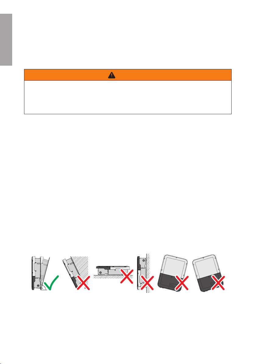
Permitted and prohibited mounting positions:
☐ The product may only be mounted in a permitted position. This will ensure that no moisture can
penetrate the product.
☐ The product should be mounted in such way that display messages and LED signals can be
read without difficulty.
Figure 3 : Permitted and prohibited mounting positions
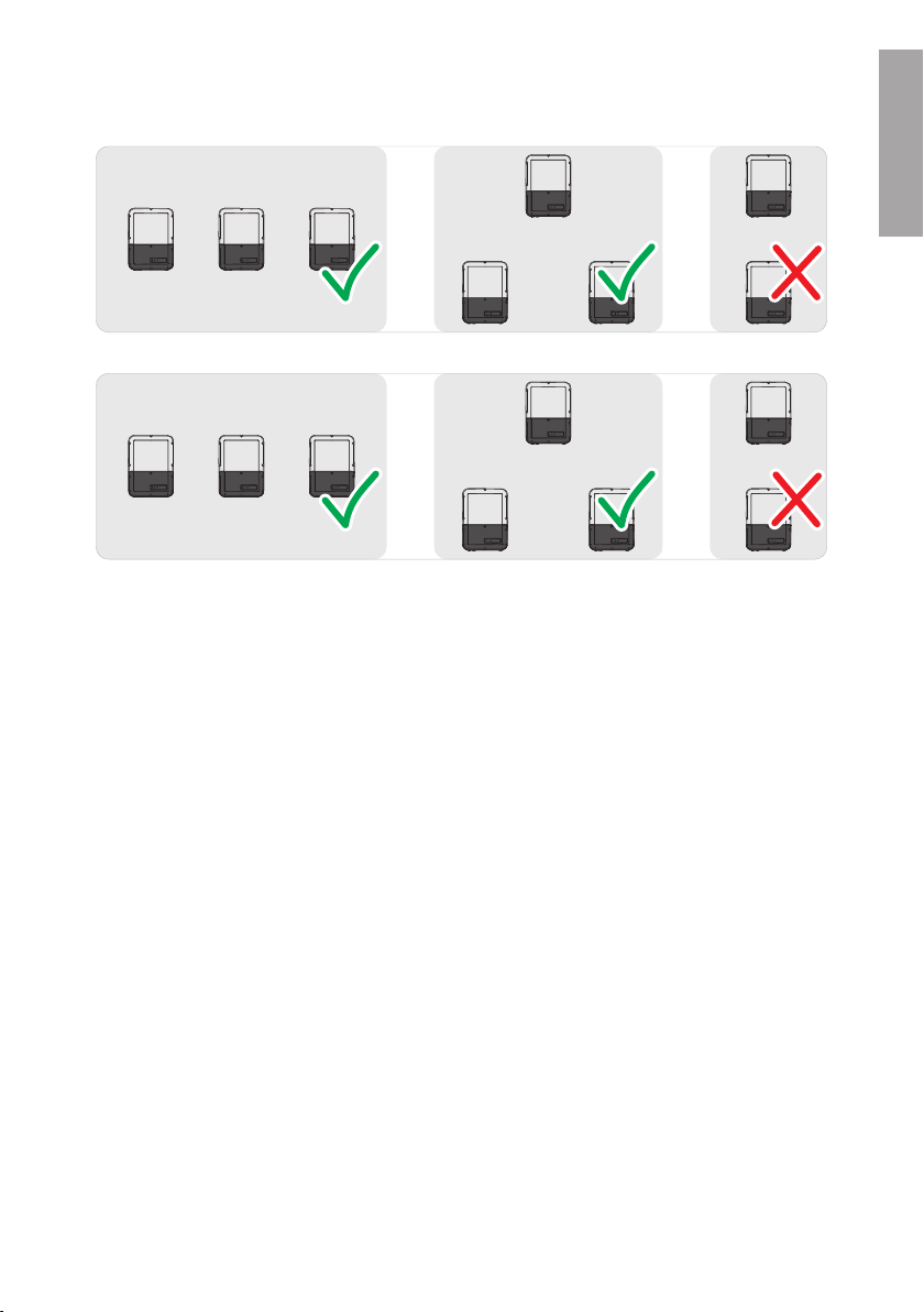
☐ Do not mount multiple inverters directly above one another.
Installation ManualSBxx-1SP-US-40-IA-xx-1522
SMA Solar Technology AG
SUNNY BOY
SUNNY BOY
SUNNY BOY
Sunny Boy 3.0-US / 3.8-US / 5.0-US / 6.0-US
Sunny Boy 7.0-US / 7.7-US
SUNNY BOY
SUNNY BOY
SUNNY BOY
SUNNY BOY
SUNNY BOY
SUNNY BOY
SUNNY BOY
SUNNY BOY
SUNNY BOY
SUNNY BOY
SUNNY BOY
SUNNY BOY
SUNNY BOY
Figure 4 : Permissible and impermissible mounting positions of multiple inverters
5 Mounting
ENGLISH
Installation Manual SBxx-1SP-US-40-IA-xx-15 23
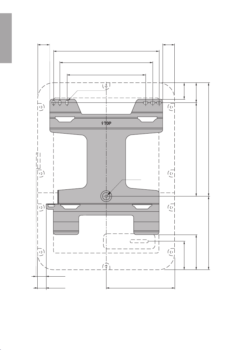
365
(14.37)
306
(12.05)
362.4
(14.27)
411
(16.18)
Ø 9
(0.35)
9 x 18
(0.35 x 0.71)
61
(2.40)
32.8
(1.29)
34.4
(1.35)
46
(1.81)
46
(1.81)
140
(5.51)
290
(11.42)
439.6
(17.31)
74.6
(2.94)
266
(10.5)
108
(4.25)
ENGLISH
5 Mounting
Dimensions for mounting:
SMA Solar Technology AG
Figure 5 : Position of the anchoring points(Dimensions in mm (in))
Installation ManualSBxx-1SP-US-40-IA-xx-1524
SMA Solar Technology AG
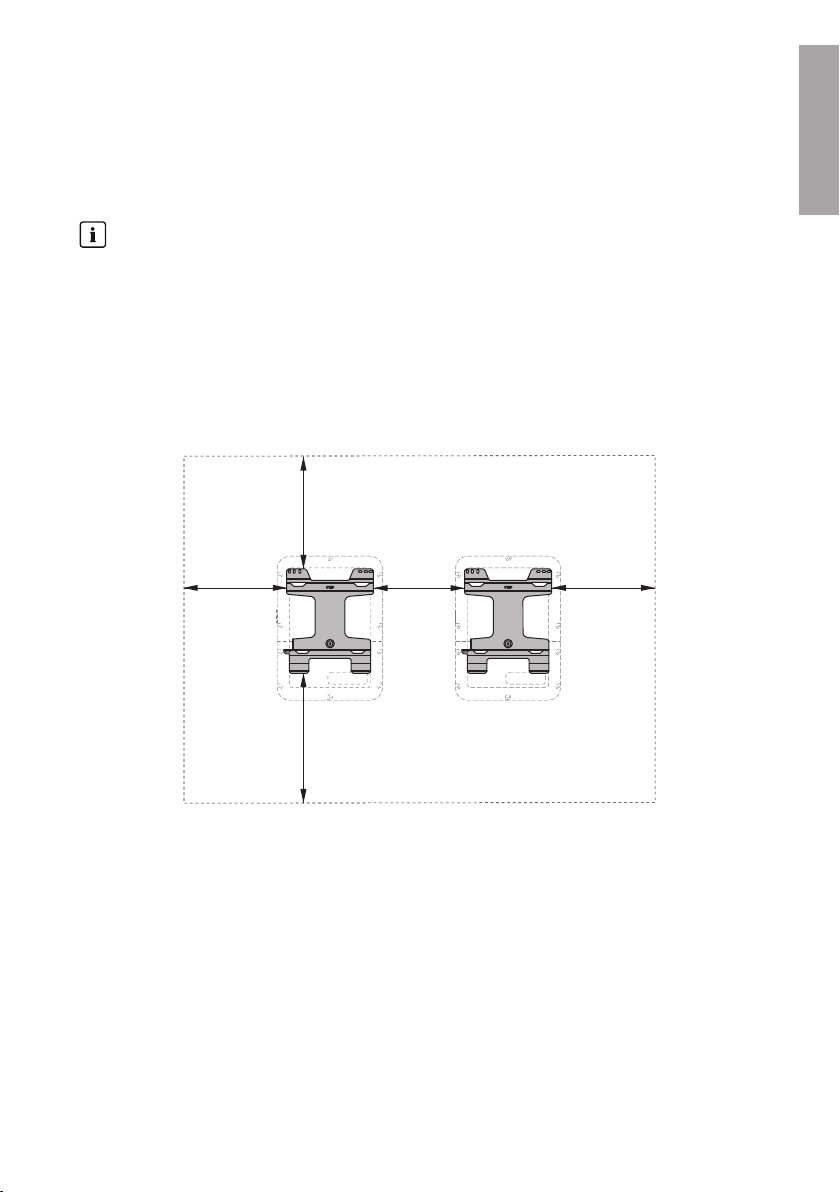
700
(27.56)
600
(23.62)
550
(21.64)
500
(19.69)
550
(21.64)
5 Mounting
Recommended Clearances:
To guarantee optimal operation and adequate heat dissipation for the inverter as well as a good
connection quality when using the SMACellularLTEModemKit, the following requirements for
clearances should be observed. This will prevent the inverter power output from being reduced due
to excessive temperatures. However, smaller clearances are permitted without causing any risk.
Prescribed clearances in accordance with the
Canadian Electrical Code
®
CSA C22.1
National Electrical Code
Under certain conditions, the National Electrical Code® or the Canadian Electrical Code
®
or
®
CSA C22.1 specify greater clearances.
• Ensure that the prescribed clearances in accordance with the National Electrical Code
®
or Canadian Electrical Code® CSA C22.1 are adhered to.
☐ Maintain the recommended clearances to walls as well as to other inverters or objects.
☐ If multiple inverters are mounted in areas with high ambient temperatures, increase the
clearances between the inverters and ensure sufficient fresh-air supply.
ENGLISH
Figure 6 : Recommended clearances(Dimensions in mm (in))
Installation Manual SBxx-1SP-US-40-IA-xx-15 25
ENGLISH
5 Mounting
SMA Solar Technology AG
5.2 Mounting the Inverter
Additionally required mounting material (not included in the scope of delivery):
☐ Three screws suitable for the support surface (diameter: 8mm (5/16in))
☐ Three washers suitable for the screws
☐ Where necessary, 3 screw anchors suitable for the support surface and the screws
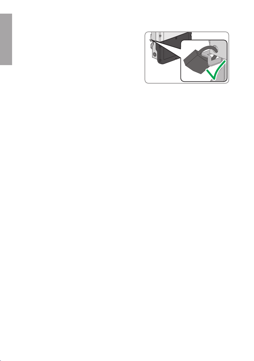
☐ To secure the inverter against theft: one padlock suitable for outdoor use
☐ Padlock dimensions:
– Diameter of the shackle: 8mm to 10mm (0.31in to 0.39in)
– Width of the shackle (inner dimension): 30mm to 40mm (1.18in to 1.57in)
– Height of the shackle (inner dimension): 30mm to 40mm (1.18in to 1.57in)
CAUTION
Risk of injury due to weight of product
Injuries may result if the product is lifted incorrectly or dropped while being transported or when
attaching it to or removing it from the wall mounting bracket.
• Transport and lift the product carefully. Take the weight of the product into account.
• Wear suitable personal protective equipment for all work on the product.
The Connection Unit and Power Unit can be disconnected from one another
to make mounting easier
If the local conditions make it difficult to mount the entire inverter, you can disconnect the
Connection Unit and Power Unit from each other if the ambient temperature is at least 0°C
(32°F) and there is no frost. This way, you can transport each enclosure part and also attach
to the wall mounting bracket individually. Then, during assembly, both enclosure parts must be
joined again. A detailed description for how to disconnect the Connection Unit and Power
Unit from each other and to individually mount them to the wall mounting bracket can be
found on the Internet under www.SMA-Solar.com.
Procedure:
1.
CAUTION
Risk of injury due to damaged cables
There may be power cables or other supply lines (e.g. gas or water) routed in the wall.
• Ensure that no lines are laid in the wall which could be damaged when drilling holes.
Installation ManualSBxx-1SP-US-40-IA-xx-1526
SMA Solar Technology AG
T
OP
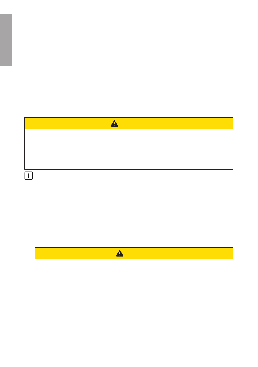
2. Align the wall mounting bracket horizontally on the
wall and use it to mark the position of the drill holes.
Here, use at least one hole each, to the right and
left, and the hole at the bottom center.
3. Set the wall mounting bracket aside and drill the marked holes.
4. Insert screw anchors into the drill holes if the support surface requires them.
5. Secure the wall mounting bracket horizontally using screws and washers.
6. Hook the inverter into the wall mounting bracket.
Here, the lugs on the rear side of the Power Unit
must be hooked into the upper recesses and the lugs
in the Connection Unit into the lower recesses in the
wall mounting bracket.
5 Mounting
ENGLISH
7. Check whether the inverter is securely in place.
If the Connection Unit can be moved forward, the lugs on the rear side of the Connection Unit
are not hooked into the lower recesses in the wall mounting bracket. Remove the inverter from
the wall mounting bracket and hook it in again.
Once the Connection Unit cannot be moved forward, the inverter is securely in place.
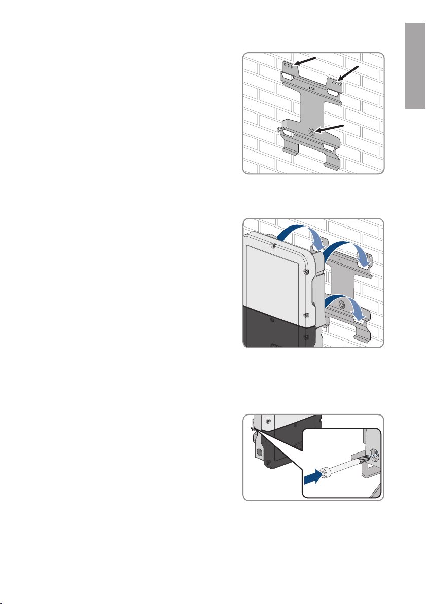
8. Secure the inverter to the wall mounting bracket. To
do this, insert the screw M5x60 through the hole on
the left side of the PowerUnit using a Torx
screwdriver (TX25) and tighten it (TX25, torque: 1.7
Nm ± 0.3Nm (15.06in-lb ± 2.65in-lb)).
9. If the inverter is to be protected against theft, attach a padlock:
Installation Manual SBxx-1SP-US-40-IA-xx-15 27
ENGLISH
5 Mounting
• To do this, guide the shackle of the padlock
through the provided hole on the left side of the
Power Unit and close the shackle.
• Keep the key of the padlock in a safe place.
SMA Solar Technology AG
Installation ManualSBxx-1SP-US-40-IA-xx-1528
SMA Solar Technology AG
B
A
C
D
6 Electrical Connection
6 Electrical Connection
6.1 Overview of the Connection Area
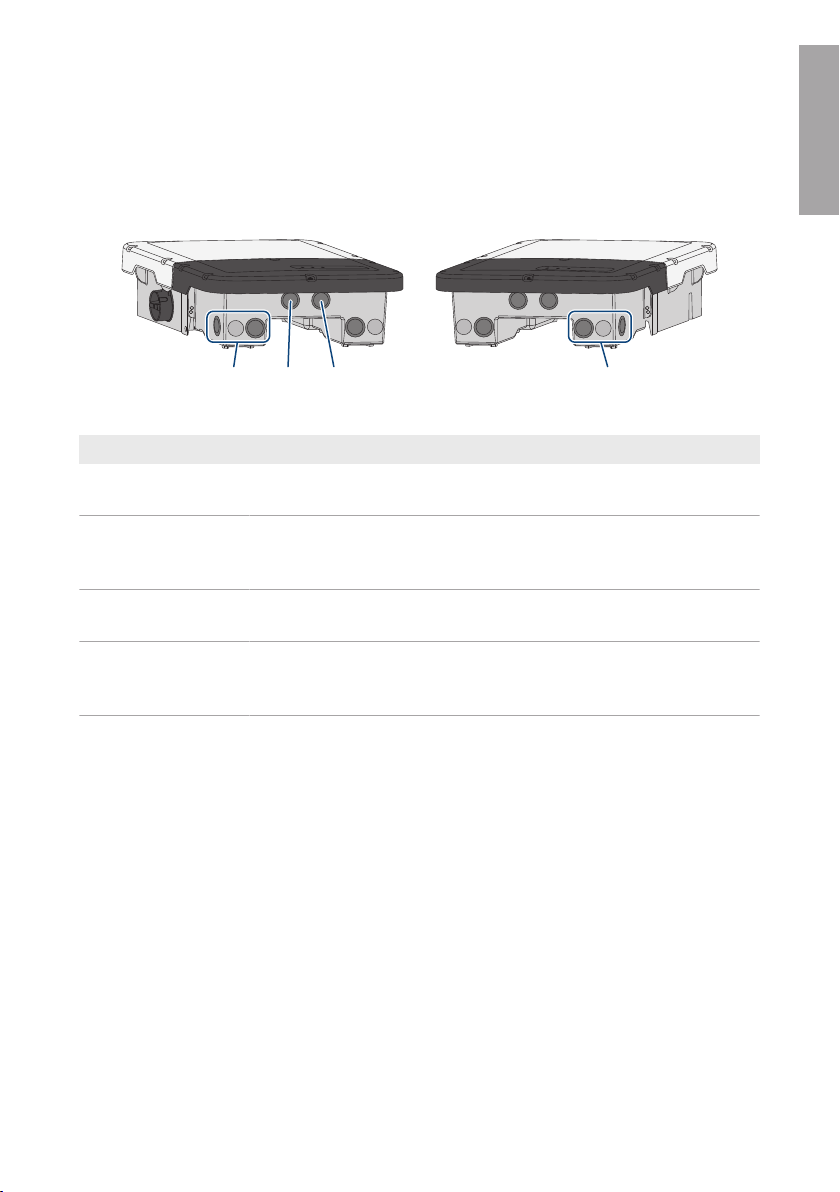
6.1.1 View from Below
Figure 7 : Enclosure openings at the bottom of the inverter
Position Designation
A Enclosure opening for DC connection (for 21mm (0.75in) trade size
conduits)
B Enclosure opening for the connection cables of the Antenna Extension Kit
and, if needed, for other data cables (for 21mm (0.75in) trade size
conduits)
C Enclosure opening for the network cables and, if needed, for other data
cables (for 21mm (0.75in) trade size conduits)
D Enclosure opening for the AC connection and the connection cables of
the outlet and, if necessary, for the switch for the secure power supply operation (for 21mm (0.75in) trade size conduits)
ENGLISH
Installation Manual SBxx-1SP-US-40-IA-xx-15 29
COM
DC-in
SPS
AC-out
D-IN
SPS
A B
M1
X1 X2
M2
ANT.
FCC ID: SVF-KP20
IC: 9440A-KP20
Max. 30V DC
DISPLAY
BAT MFR
USB
A
B
C
D F
G
O H
J
P
K
L
M
N
I
E
Q
ENGLISH
6 Electrical Connection
SMA Solar Technology AG
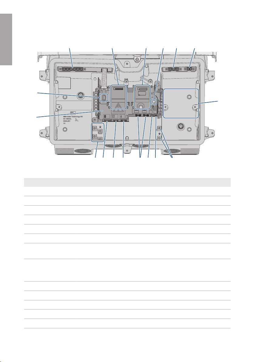
6.1.2 Interior View
Figure 8 : Connection areas in the interior of the inverter
Position Designation
A
B
C
D
E
F
G Installation location for accessories (optional) approved by SMA Solar
H Equipment grounding terminal for the equipment grounding conductor of
I
J
K
L
M
DC-in slot for DC connection
Module slot M1
Module slot M2
ANT. slot for connecting the Antenna Extension Kit (optional)
AC-out slot for the AC connection
SPS slot for connecting the secure power supply outlet
Technology AG
the utility grid, the outlet for secure power supply operation and, if necessary, an additional grounding or for the equipotential bonding
SPS slot for connecting the secure power supply switch
Pin connector D-IN is not used
Network ports A and B for connecting a router or network switch
USB port for connecting a USB flash drive (for service purposes)
MFR slot for connection to the multifunction relay
Installation ManualSBxx-1SP-US-40-IA-xx-1530
 Loading...