

SMA SUNNY BOY 3000TL, SUNNY BOY 4000TL, SUNNY BOY 5000TL Installation Manual
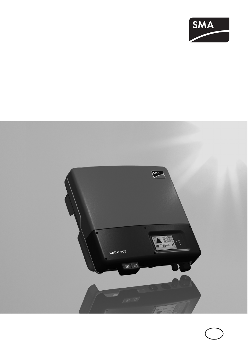
PV Inverter
SUNNY BOY 3000TL / 4000TL / 5000TL
Installation Guide
SB30TL_40TL_50TL-IEN085120 | IME-TB-SBXTL-20 | Version 2.0
EN
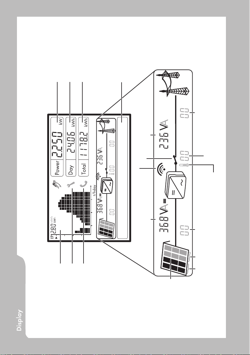
Daily energy
Current output
Total energy generated since the Sunny
Boy was installed
Text line for displaying an event
Grid event number
Output voltage / output current
Grid relay
the daily energy values of the past 16 days
Knocking on the lower lid:
• Activating the background illumination
• Switching through the line display
• Switching through the energy values of the past 16 feed-in hours to
Bluetooth connection to other Sunny Boys
Input voltage / input current
Device fault
Please contact SMA.
Failure that can be removed on-site
(see chapter 10.2 )
Sunny Boy event number
PV generator event number
AB
Power reduction due to excessive temperature
• Cleaning the fan, if necessary (only for Sunny Boy 4000TL / 5000TL)
• Sunny Boy might need better ventilation
Sunny Boy 4000TL / 5000TL:
switching between input A and B
every 10 seconds
Sunny Boy 3000TL: display of both
Power curve of the past 16 feed-in hours or
past 16 days (switching the display is done by
knocking on the lid)
modules

SMA Solar Technology AG
Table of Contents
1 Notes on this Manual. . . . . . . . . . . . . . . . . . . . . . . . . . . . . . 7
1.1 Validity . . . . . . . . . . . . . . . . . . . . . . . . . . . . . . . . . . . . . . . . . . . . 7
1.2 Target Group . . . . . . . . . . . . . . . . . . . . . . . . . . . . . . . . . . . . . . . 7
1.3 Storage of Manuals . . . . . . . . . . . . . . . . . . . . . . . . . . . . . . . . . . 7
1.4 Additional Information . . . . . . . . . . . . . . . . . . . . . . . . . . . . . . . . 7
1.5 Symbols Used . . . . . . . . . . . . . . . . . . . . . . . . . . . . . . . . . . . . . . . 8
2 Safety . . . . . . . . . . . . . . . . . . . . . . . . . . . . . . . . . . . . . . . . . . 9
2.1 Appropriate Usage. . . . . . . . . . . . . . . . . . . . . . . . . . . . . . . . . . . 9
2.2 Safety Instructions . . . . . . . . . . . . . . . . . . . . . . . . . . . . . . . . . . . 11
3 Unpacking. . . . . . . . . . . . . . . . . . . . . . . . . . . . . . . . . . . . . . 12
3.1 Scope of Delivery . . . . . . . . . . . . . . . . . . . . . . . . . . . . . . . . . . . 12
3.2 Check for Transport Damage . . . . . . . . . . . . . . . . . . . . . . . . . . 12
3.3 Identification of the Sunny Boy . . . . . . . . . . . . . . . . . . . . . . . . . 12
4 Mounting the Device . . . . . . . . . . . . . . . . . . . . . . . . . . . . . 13
4.1 Selection of the Mounting Location . . . . . . . . . . . . . . . . . . . . . 13
4.1.1 Dimensions and Weight . . . . . . . . . . . . . . . . . . . . . . . . . . . . . . . . . . . . . . . . 13
4.1.2 Ambient Conditions. . . . . . . . . . . . . . . . . . . . . . . . . . . . . . . . . . . . . . . . . . . . 14
4.1.3 Safety clearances . . . . . . . . . . . . . . . . . . . . . . . . . . . . . . . . . . . . . . . . . . . . . 14
4.1.4 Position . . . . . . . . . . . . . . . . . . . . . . . . . . . . . . . . . . . . . . . . . . . . . . . . . . . . . 15
4.2 Mounting Instructions . . . . . . . . . . . . . . . . . . . . . . . . . . . . . . . . 15
4.2.1 Mounting with Wall Bracket . . . . . . . . . . . . . . . . . . . . . . . . . . . . . . . . . . . . . 15
4.2.2 Mounting with Top Hat Rail . . . . . . . . . . . . . . . . . . . . . . . . . . . . . . . . . . . . . 19
5 Electrical Connection . . . . . . . . . . . . . . . . . . . . . . . . . . . . . 22
5.1 Connection Area Overview . . . . . . . . . . . . . . . . . . . . . . . . . . . 23
5.2 Connection to the Public Grid (AC) . . . . . . . . . . . . . . . . . . . . . 24
Installation Guide SB30TL_40TL_50TL-IEN085120 3

SMA Solar Technology AG
5.3 Connection of the PV generator (DC) . . . . . . . . . . . . . . . . . . . . 30
5.3.1 Connection requirements Sunny Boy 3000TL. . . . . . . . . . . . . . . . . . . . . . . . 30
5.3.2 Connection requirements Sunny Boy 4000TL / 5000TL . . . . . . . . . . . . . . . 31
5.3.3 Connection Procedure. . . . . . . . . . . . . . . . . . . . . . . . . . . . . . . . . . . . . . . . . . 32
5.4 Setting the installation country . . . . . . . . . . . . . . . . . . . . . . . . . 35
5.4.1 Checking the Country Configuration. . . . . . . . . . . . . . . . . . . . . . . . . . . . . . . 36
5.4.2 Configuration with rotary switches . . . . . . . . . . . . . . . . . . . . . . . . . . . . . . . . 38
5.5 Communication. . . . . . . . . . . . . . . . . . . . . . . . . . . . . . . . . . . . . 39
5.5.1 Bluetooth . . . . . . . . . . . . . . . . . . . . . . . . . . . . . . . . . . . . . . . . . . . . . . . . . . . . 39
5.5.2 Fault Signaling Contact. . . . . . . . . . . . . . . . . . . . . . . . . . . . . . . . . . . . . . . . . 40
5.5.3 Installing a Communication Module . . . . . . . . . . . . . . . . . . . . . . . . . . . . . . . 43
6 Commissioning . . . . . . . . . . . . . . . . . . . . . . . . . . . . . . . . . . 45
7 Opening and Closing. . . . . . . . . . . . . . . . . . . . . . . . . . . . . 46
7.1 Opening the Sunny Boy . . . . . . . . . . . . . . . . . . . . . . . . . . . . . . 46
7.2 Closing the Sunny Boy . . . . . . . . . . . . . . . . . . . . . . . . . . . . . . . 48
8 Maintenance. . . . . . . . . . . . . . . . . . . . . . . . . . . . . . . . . . . . 50
8.1 Checking Heat Dissipation . . . . . . . . . . . . . . . . . . . . . . . . . . . . 50
8.1.1 Cleaning of the fan (only for Sunny Boy 4000TL / 5000TL) . . . . . . . . . . . . 50
8.1.2 Testing the fan (only for Sunny Boy 4000TL / 5000TL) . . . . . . . . . . . . . . . . 51
8.2 Inspection of the Electronic Solar Switch (ESS). . . . . . . . . . . . . 52
9 SD Card Slot . . . . . . . . . . . . . . . . . . . . . . . . . . . . . . . . . . . . 53
10 Messages . . . . . . . . . . . . . . . . . . . . . . . . . . . . . . . . . . . . . . 55
10.1 Update messages . . . . . . . . . . . . . . . . . . . . . . . . . . . . . . . . . . . 55
10.2 Error Messages. . . . . . . . . . . . . . . . . . . . . . . . . . . . . . . . . . . . . 56
11 Troubleshooting . . . . . . . . . . . . . . . . . . . . . . . . . . . . . . . . . 62
11.1 Ground fault testing . . . . . . . . . . . . . . . . . . . . . . . . . . . . . . . . . 62
11.2 Checking the Varistors . . . . . . . . . . . . . . . . . . . . . . . . . . . . . . . 63
4 SB30TL_40TL_50TL-IEN085120 Installation Guide

SMA Solar Technology AG
12 Decommissioning . . . . . . . . . . . . . . . . . . . . . . . . . . . . . . . . 66
12.1 Disassembly . . . . . . . . . . . . . . . . . . . . . . . . . . . . . . . . . . . . . . . 66
12.2 Replacement of the housing covers . . . . . . . . . . . . . . . . . . . . . 66
12.3 Packaging . . . . . . . . . . . . . . . . . . . . . . . . . . . . . . . . . . . . . . . . . 68
12.4 Storage . . . . . . . . . . . . . . . . . . . . . . . . . . . . . . . . . . . . . . . . . . . 68
12.5 Disposal . . . . . . . . . . . . . . . . . . . . . . . . . . . . . . . . . . . . . . . . . . 68
13 Technical Data . . . . . . . . . . . . . . . . . . . . . . . . . . . . . . . . . . 69
14 Accessories . . . . . . . . . . . . . . . . . . . . . . . . . . . . . . . . . . . . . 72
15 Contact . . . . . . . . . . . . . . . . . . . . . . . . . . . . . . . . . . . . . . . . 73
Installation Guide SB30TL_40TL_50TL-IEN085120 5

SMA Solar Technology AG
6 SB30TL_40TL_50TL-IEN085120 Installation Guide

SMA Solar Technology AG Notes on this Manual
1 Notes on this Manual
1.1 Validity
This installation guide describes the installation and commissioning of SMA Solar Technology
inverters of the type Sunny Boy 3000TL (SB 3000TL-20), 4000TL (SB 4000TL-20) and 5000TL
(SB 5000TL-20).
1.2 Target Group
Only qualified electricians may install and commission Sunny Boy units.
1.3 Storage of Manuals
All manuals for the Sunny Boy and the installed components must be stored with the system
documentation and be accessible at all times.
1.4 Additional Information
You can download additional information from the download area at www.SMA.de. Technical
information on the subjects of "laying out of a line circuit breaker" or parameter descriptions for
example is available here.
Installation Guide SB30TL_40TL_50TL-IEN085120 7
Notes on this Manual SMA Solar Technology AG
1.5 Symbols Used
The following types of safety instructions and general information appear in this document:
DANGER!
"DANGER" indicates a hazardous situation which, if not avoided, will directly result in
death or serious injury.
WARNING!
"WARNING" indicates a hazardous situation which, if not avoided, could result in death
or serious injury.
CAUTION!
"CAUTION" indicates a hazardous situation which, if not avoided, could result in minor or
moderate injury.
ATTENTION!
"ATTENTION" indicates a situation that can result in property damage if not avoided.
Information
Information provides tips that are valuable for the optimal operation of the product.
8 SB30TL_40TL_50TL-IEN085120 Installation Guide
SMA Solar Technology AG Safety
2 Safety
2.1 Appropriate Usage
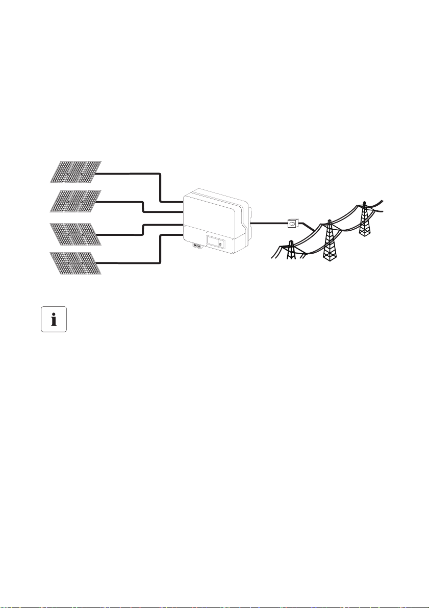
The Sunny Boy is a PV inverter which converts the DC current of a PV generator to AC current and
feeds it into the public grid.
Principle of a PV system with this Sunny Boy
Input A
Distribution
Input B
Sunny Boy
PV module
Input B
Input B is only available on the Sunny Boys 4000TL and 5000TL.
Public grid
The Sunny Boy may only be operated with PV generators (modules and cabling) of protection class
II. Do not connect any sources of energy other than PV modules to the Sunny Boy.
PV modules with large capacities relative to ground, such as thin-film modules with cells on a metallic
substrate, are only to be implemented if their coupling capacity is below 50 nF/kWp.
During grid feeding, a leakage current flows from the cells to ground. The magnitude of this current
depends on the manner in which the modules are installed and, to no small extent, on the weather
(rain, snow). This operational leakage current is not to exceed 50 mA.
When designing the PV system, ensure that the values comply with the permitted operating range of
all components at all times. The free design program "Sunny Design"
(www.SMA.de/en/SunnyDesign) will assist you. The manufacturer of the PV modules must have
approved the modules for use with this Sunny Boy unit. You must also ensure that all measures
recommended by the module manufacturer for long-term maintenance of the module properties are
take n (see also Technical Information "Module Techn ology", in the download area of www.SMA.de).
Installation Guide SB30TL_40TL_50TL-IEN085120 9

Safety SMA Solar Technology AG
Do not use the Sunny Boy for purposes other than those described here. Alternative uses,
modifications to the Sunny Boy or the installation of components not expressly recommended or sold
by SMA Solar Technology invalidates the warranty claims and operation permission.
Authorized Countries
The Sunny Boys 3000TL / 4000TL / 5000TL meet, with the corresponding settings, the requirements
of the following standards and guidelines (as at 12/2008):
• VDE 0126-1-1 (02.2006)
• DK 5940 Ed. 2.2 (02.2006) (Certification of Sunny Boy 3000TL still in process)
• RD 1663/2000 (2000)
• PPC (06.2006)
• AS4777 (2005)
• EN 50438 (12.2007)
Upon request, SMA Solar Technology can set network parameters in-house according to customer
specifications for other countries / installation locations, once these have been tested by SMA Solar
Technology.
You can subsequently make adjustments via changes to the software parameters using relevant
communications products (e.g. Sunny Data Control). For this, however, a personal password is
required, which you can receive from the SMA Serviceline upon request.
10 SB30TL_40TL_50TL-IEN085120 Installation Guide
SMA Solar Technology AG Safety
2.2 Safety Instructions
DANGER!
Danger to life due to high voltages in the Sunny Boy!
• All work on the Sunny Boy must only be carried out by a qualified electrician.
CAUTION!
Danger of burn injuries due to hot housing parts!
During operation, the upper cover of the housing and the housing body may become hot.
• Only touch the lower housing cover during operation.
CAUTION!
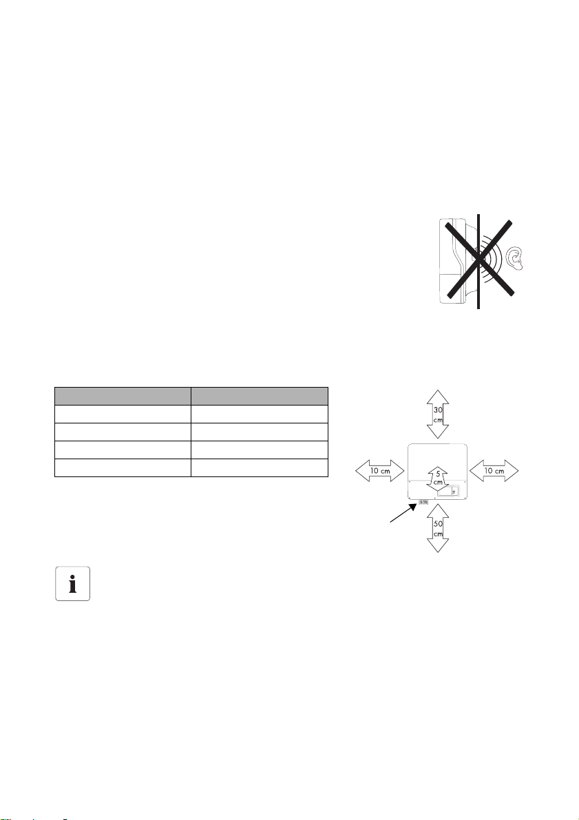
Possible health risks due to the effects of radiation!
• Do not remain within a distance of less than 20 cm from the Sunny Boy for long
periods of time.
Grounding the PV generator
Comply with the local requirements for grounding the modules and the PV generator.
SMA Solar Technology recommends connecting the generator frame and other electricity
conducting surfaces such that there is continuous conduction and to connect them to the
ground in order to reach maximum protection for property and persons.
Installation Guide SB30TL_40TL_50TL-IEN085120 11
Unpacking SMA Solar Technology AG
3 Unpacking
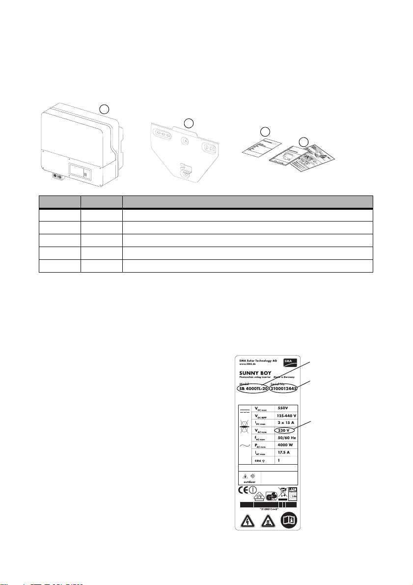
3.1 Scope of Delivery
A
B
Object Quantity Description
A 1 Sunny Boy
B 1 wall bracket
C 1 Set of documents with explanations and certificates
D 1 Installation guide, including user manual
optional 1 Installation guide for communication module
3.2 Check for Transport Damage
Check the Sunny Boy for visible external damage, such as cracks in the housing or display. Please
contact your dealer if you find any damage.
C
D
3.3 Identification of the Sunny Boy
You ca n identify the Sunny Boy usi ng the name plate. The
name plate is on the right side of the housing.
12 SB30TL_40TL_50TL-IEN085120 Installation Guide
Device type and
version
Serial number:
Grid voltage
(suitable for
220 - 240 V)
SMA Solar Technology AG Mounting the Device
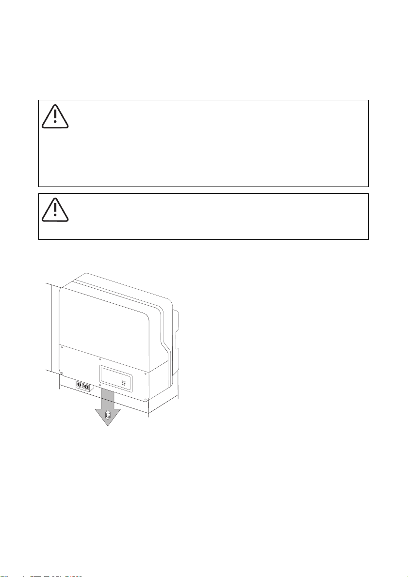
4 Mounting the Device
4.1 Selection of the Mounting Location
WARNING!
Danger to life due to fire or explosion!
The Sunny Boy housing can become hot during operation.
• Do not mount the Sunny Boy on flammable construction materials.
• Do not mount the Sunny Boy in areas where highly flammable materials are stored.
• Do not mount the Sunny Boy in areas where there is a risk of explosion.
CAUTION!
Danger of burn injuries due to hot housing parts!
• Mount the Sunny Boy such that it cannot be touched inadvertently.
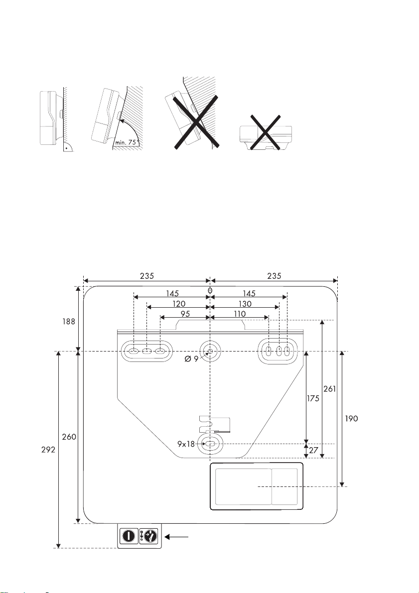
4.1.1 Dimensions and Weight
m
m
5
4
4
4
7
0
m
m
Sunny Boy 3000TL: 22kg
Sunny Boy 4000TL / 5000TL: 25 kg
Installation Guide SB30TL_40TL_50TL-IEN085120 13
m
m
0
8
1
Mounting the Device SMA Solar Technology AG
4.1.2 Ambient Conditions
• The mounting location and mounting method must be suitable for the weight and dimensions.
• Mount on a solid surface.
• The mounting location must be accessible at all times.
• The ambient temperature should be below 40 °C at all times to guarantee optimal operation.
• Do not expose the Sunny Boy to direct sunlight, in order to avoid power reduction due to
excessive heating.
• In a living area, do not mount the unit on
plasterboard walls etc. in order to avoid audible
vibrations.
The Sunny Boy can make noises when in use which
can be considered a nuisance when installed in a
living area.
4.1.3 Safety clearances
Observe the following minimum clearances to walls, other devices or objects to guarantee sufficient
heat dissipation and enough space for pulling the Electronic Solar Switch handle.
Direction Minimum clearance
sides 10 cm
above 30 cm
below 50 cm
front 5 cm
Electronic
Solar
Switch
Multiple Sunny Boys installed in areas with high ambient temperatures
If necessary, increase the clearance and ensure that the supply of cool air is sufficient to
cool the Sunny Boys.
14 SB30TL_40TL_50TL-IEN085120 Installation Guide
SMA Solar Technology AG Mounting the Device
4.1.4 Position
• Install upright or tilted backwards by max. 15°.
• Never install the device with a forward tilt.
• Do not install horizontally.
• Install at eye level to allow operating status to be read at all times.
4.2 Mounting Instructions
4.2.1 Mounting with Wall Bracket
Display
Electronic Solar Switch
Installation Guide SB30TL_40TL_50TL-IEN085120 15
Dimensions in mm
Mounting the Device SMA Solar Technology AG
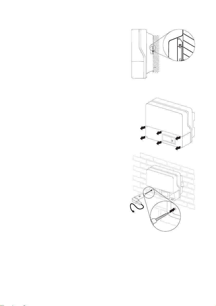
1. Use the wall mounting bracket as a drilling template and mark the positions of the drill holes.
Number of drill holes used
• When wall mounting the unit, use at least two of the horizontal holes and the lowest
hole in the middle.
• Use the two holes in the middle when mounting to a pillar.
2. Secure the wall bracket using suitable screws
(at least 6 mm in diameter) and washers
(min. outer diameter: 18mm).
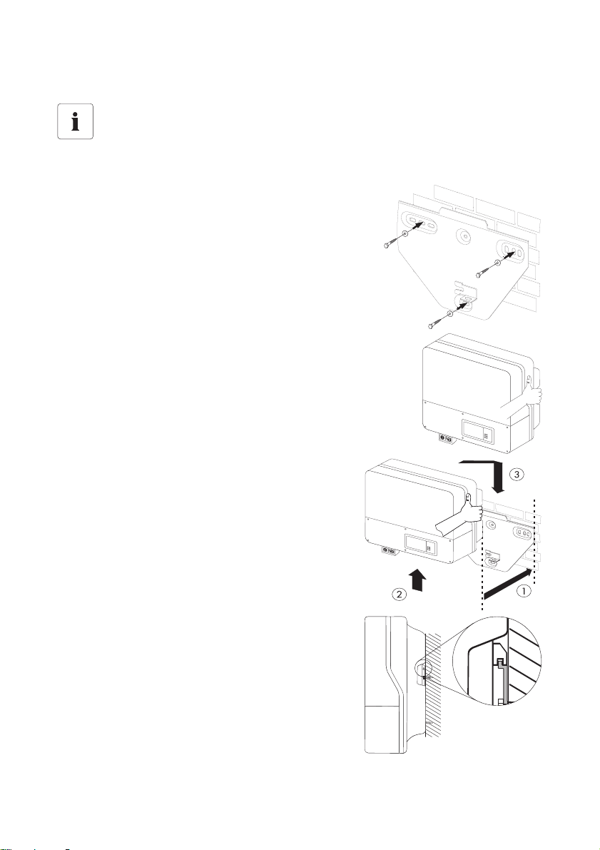
3. Transport the Sunny Boy using the handles at the
sides of the Sunny Boy.
4. Attach the Sunny Boy to the wall bracket slightly to
the left of its final position.
The right edge of the rear wall of the Sunny Boy
must be flu sh with the ri ght edg e of the wall b racket.
5. Check both sides for correct positioning.
16 SB30TL_40TL_50TL-IEN085120 Installation Guide
SMA Solar Technology AG Mounting the Device
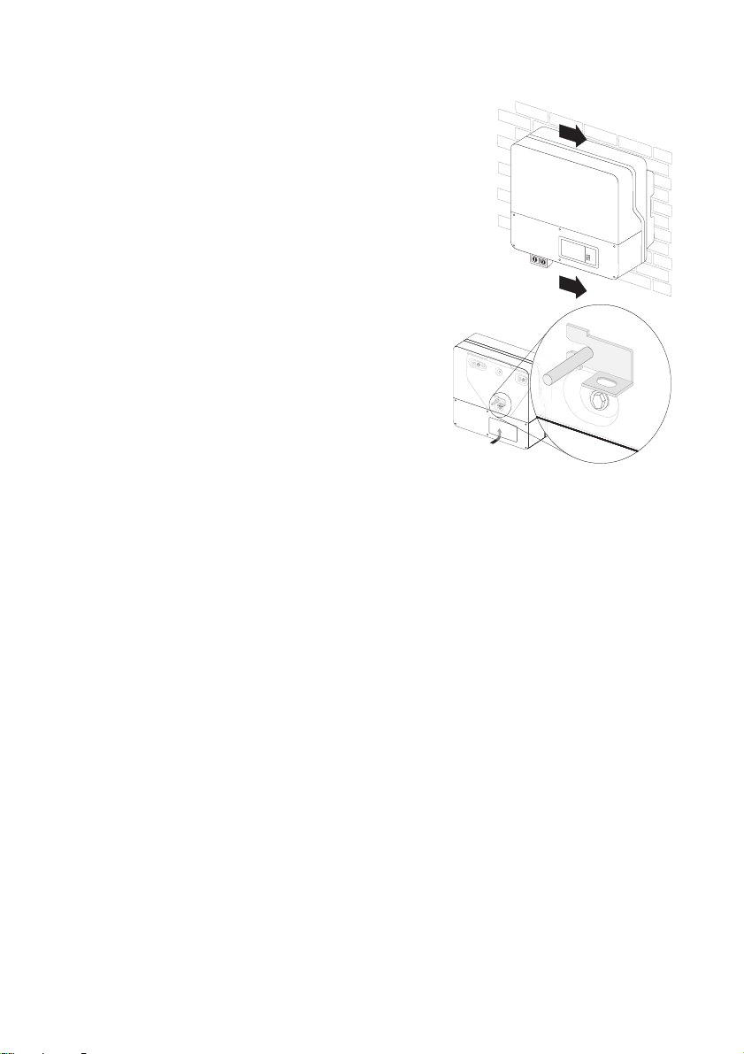
6. Push the Sunny Boy to the right on the wall bracket,
until it locks into place with the locking bolt on the
rear wall.
7. Check for correct position.
Installation Guide SB30TL_40TL_50TL-IEN085120 17

Mounting the Device SMA Solar Technology AG
Optional anti-theft protection
The Sunny Boy can be secured to the wall bracket with a
lock to protect it against theft.
The lock must meet the following requirements:
•Size:
A: 6 - 10 mm in diameter
B: 21 - 35 mm
C: 20 - 33 mm
D: 40 - 60 mm
E: 13 - 21 mm
• Stainless steel
• hardened shackle
•secured cylinder lock
Storing the key
Store the key carefully in case the device needs servicing.
18 SB30TL_40TL_50TL-IEN085120 Installation Guide
SMA Solar Technology AG Mounting the Device
4.2.2 Mounting with Top Hat Rail
Requirements for mounting of the top hat rail
• Use a TH-35-7.5 mounting rail compliant with DIN EN 60715.
• Use stainless steel top hat rails and screws to prevent contact corrosion.
• Mount on level surfaces only.
• Use fastening material suitable for the surface.
Take into account the weight of the Sunny Boy when selecting fastening materials.
Mounting Procedure
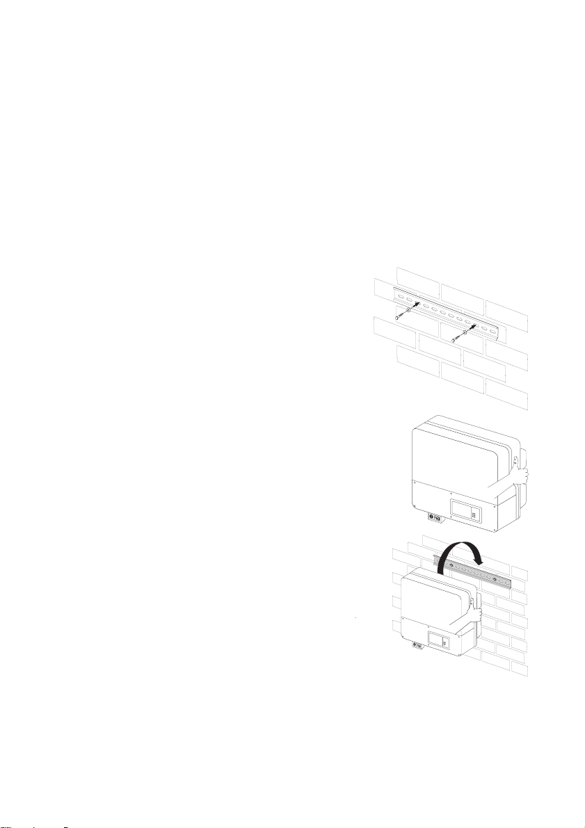
1. Use the top hat rail as a drilling template and mark the positions of the drill holes.
2. Secure the top hat rail using suitable screws
(at least 6 mm in diameter) and washers
(min. outer diameter: 18mm).
Secure one screw at least every 300 mm.
3. Transport the Sunny Boy using the handles at the
sides of the Sunny Boy.
4. Attach the Sunny Boy to the top hat rail using the
mounting opening in the rear wall.
Installation Guide SB30TL_40TL_50TL-IEN085120 19
Mounting the Device SMA Solar Technology AG
5. Check both sides for correct positioning.
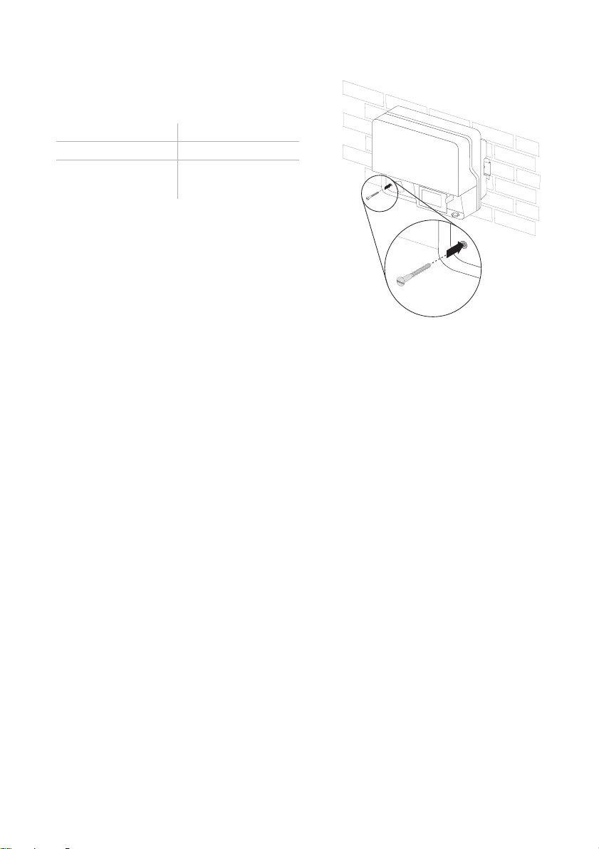
In order to prevent the Sunny Boy being pulled off, you must also screw it to the wall. To do so,
proceed as follows:
1. Remove the Electronic Solar Switch by pulling it
downwards.
2. Loosen all six non-removable lid screws and
remove the cover.
3. Drill through hole in the rear wall of the housing.
4. Use a suitable drill bit at least 120 mm in length.
5. Insert a wall anchor of the correct size.
20 SB30TL_40TL_50TL-IEN085120 Installation Guide
SMA Solar Technology AG Mounting the Device
6. Secure the Sunny Boy with a screw.
The screw must meet the following requirements:
Length: min. 100 mm
Diameter: >8 mm
Screw head: not hexagon head,
not countersunk
7. Check that the unit is secure.
Installation Guide SB30TL_40TL_50TL-IEN085120 21
Electrical Connection SMA Solar Technology AG
5 Electrical Connection
WARNING!
Electric shock due to short circuit!
If cables with different voltages are laid parallel to one another, short circuits can result if
the cable insulation becomes damaged.
• Lay all cables separately.
ATTENTION!
Electrostatic discharges can damage the Sunny Boy!
Internal components of the Sunny Boy can be irreparably damaged by static discharge.
• Ground yourself before touching a component.
22 SB30TL_40TL_50TL-IEN085120 Installation Guide
SMA Solar Technology AG Electrical Connection
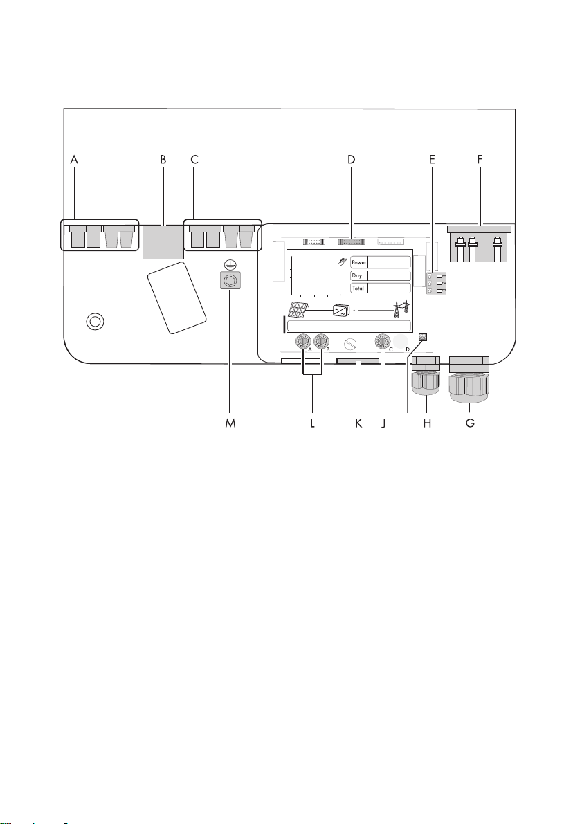
5.1 Connection Area Overview
A Plug connectors for connecting the strings (input area A)
B Electronic Solar Switch (ESS) socket
Plug connectors for connecting the strings (input area B)(only on Sunny Boy 4000TL / 5000TL)
C
D Plug for connecting the RS485 module (optional)
E Plug for connecting the fault signaling contact (optional)
F Terminal for grid connection
G Cable opening for grid connection (AC) (12 - 25 mm)
H Cable opening for the fault signaling contact (6 - 12 mm) (optional)
I Jumper for setting the language to English
J Rotary switch for setting Bluetooth communication
K Cable opening for communication via RS485 (optional)
L Rotary switch for country configuration
M Grounding terminal for additional grounding of the Sunny Boy
Installation Guide SB30TL_40TL_50TL-IEN085120 23
 Loading...