

SMA Sunny Boy 2500, Sunny Boy 3000 Installation Manual
SB25-30-IA-en-51 | IMEN-SB25_30 | Version 5.1
EN
PV Inverter
SUNNY BOY 2500/3000
Installation Manual


SMA Solar Technology AG Table of Contents
Installation Manual SB25-30-IA-en-51 3
Table of Contents
1 Information on this Manual. . . . . . . . . . . . . . . . . . . . . . . . . 7
1.1 Validity . . . . . . . . . . . . . . . . . . . . . . . . . . . . . . . . . . . . . . . . . . . . 7
1.2 Target Group . . . . . . . . . . . . . . . . . . . . . . . . . . . . . . . . . . . . . . . 7
1.3 Additional Information . . . . . . . . . . . . . . . . . . . . . . . . . . . . . . . . 7
1.4 Symbols Used . . . . . . . . . . . . . . . . . . . . . . . . . . . . . . . . . . . . . . . 8
2 Safety . . . . . . . . . . . . . . . . . . . . . . . . . . . . . . . . . . . . . . . . . . 9
2.1 Intended Use. . . . . . . . . . . . . . . . . . . . . . . . . . . . . . . . . . . . . . . . 9
2.2 Safety Precautions. . . . . . . . . . . . . . . . . . . . . . . . . . . . . . . . . . . 10
2.3 Explanation of Symbols . . . . . . . . . . . . . . . . . . . . . . . . . . . . . . 12
2.3.1 Symbols on the Inverter. . . . . . . . . . . . . . . . . . . . . . . . . . . . . . . . . . . . . . . . . 12
2.3.2 Symbols on the Type Label . . . . . . . . . . . . . . . . . . . . . . . . . . . . . . . . . . . . . . 13
3 Unpacking. . . . . . . . . . . . . . . . . . . . . . . . . . . . . . . . . . . . . . 14
3.1 Scope of Delivery . . . . . . . . . . . . . . . . . . . . . . . . . . . . . . . . . . . 14
3.2 Identifying the Inverter . . . . . . . . . . . . . . . . . . . . . . . . . . . . . . . 15
4 Mounting. . . . . . . . . . . . . . . . . . . . . . . . . . . . . . . . . . . . . . . 16
4.1 Safety . . . . . . . . . . . . . . . . . . . . . . . . . . . . . . . . . . . . . . . . . . . . 16
4.2 Selecting the Mounting Location. . . . . . . . . . . . . . . . . . . . . . . . 16
4.3 Mounting the Inverter with the Wall Mounting Bracket . . . . . . 18
5 Electrical Connection . . . . . . . . . . . . . . . . . . . . . . . . . . . . . 20
5.1 Overview of the Connection Area . . . . . . . . . . . . . . . . . . . . . . 20
5.1.1 Exterior View . . . . . . . . . . . . . . . . . . . . . . . . . . . . . . . . . . . . . . . . . . . . . . . . . 20
5.1.2 Interior View . . . . . . . . . . . . . . . . . . . . . . . . . . . . . . . . . . . . . . . . . . . . . . . . . 21
5.2 Connection to the Power Distribution Mains (AC) . . . . . . . . . . 22
5.2.1 Conditions for the AC Connection . . . . . . . . . . . . . . . . . . . . . . . . . . . . . . . . 22
5.2.2 Connecting the Inverter to the Power Distribution Mains (AC) . . . . . . . . . . . 24
5.2.3 Connecting Additional Earthing . . . . . . . . . . . . . . . . . . . . . . . . . . . . . . . . . . 27

Table of Contents SMA Solar Technology AG
4 SB25-30-IA-en-51 Installation Manual
5.3 Setting the Display Language . . . . . . . . . . . . . . . . . . . . . . . . . . 28
5.4 PV Array Connection (DC) . . . . . . . . . . . . . . . . . . . . . . . . . . . . 28
5.4.1 Conditions for the DC Connection . . . . . . . . . . . . . . . . . . . . . . . . . . . . . . . . 28
5.4.2 Assembling the DC Connectors. . . . . . . . . . . . . . . . . . . . . . . . . . . . . . . . . . . 29
5.4.3 Opening the DC Connector . . . . . . . . . . . . . . . . . . . . . . . . . . . . . . . . . . . . . 31
5.4.4 Connecting the PV Array (DC) . . . . . . . . . . . . . . . . . . . . . . . . . . . . . . . . . . . 32
5.5 Communication. . . . . . . . . . . . . . . . . . . . . . . . . . . . . . . . . . . . . 35
5.6 Setting the Mains and Country Parameters . . . . . . . . . . . . . . . 36
5.6.1 Setting the Installation Country . . . . . . . . . . . . . . . . . . . . . . . . . . . . . . . . . . . 36
5.6.2 Setting Stand-alone Mains Operation. . . . . . . . . . . . . . . . . . . . . . . . . . . . . . 36
6 Commissioning . . . . . . . . . . . . . . . . . . . . . . . . . . . . . . . . . . 37
6.1 Commissioning the Inverter. . . . . . . . . . . . . . . . . . . . . . . . . . . . 37
6.2 Display Messages during the Startup Phase. . . . . . . . . . . . . . . 38
6.3 Self-test in Accordance with DK 5940, Ed. 2.2
(Applies to Italy Only). . . . . . . . . . . . . . . . . . . . . . . . . . . . . . . . 39
6.3.1 Starting the Self-test by Tapping . . . . . . . . . . . . . . . . . . . . . . . . . . . . . . . . . . 39
6.3.2 Completion of the Self-test. . . . . . . . . . . . . . . . . . . . . . . . . . . . . . . . . . . . . . . 39
7 Opening and Closing. . . . . . . . . . . . . . . . . . . . . . . . . . . . . 44
7.1 Safety . . . . . . . . . . . . . . . . . . . . . . . . . . . . . . . . . . . . . . . . . . . . 44
7.2 Opening the Inverter. . . . . . . . . . . . . . . . . . . . . . . . . . . . . . . . . 44
7.3 Closing the Inverter. . . . . . . . . . . . . . . . . . . . . . . . . . . . . . . . . . 47
8 Maintenance and Cleaning. . . . . . . . . . . . . . . . . . . . . . . . 49
8.1 Cleaning the Inverter. . . . . . . . . . . . . . . . . . . . . . . . . . . . . . . . . 49
8.2 Checking the Electronic Solar Switch for Wear . . . . . . . . . . . . 49
9 Troubleshooting . . . . . . . . . . . . . . . . . . . . . . . . . . . . . . . . . 51
9.1 Blink Codes. . . . . . . . . . . . . . . . . . . . . . . . . . . . . . . . . . . . . . . . 51
9.2 Error Messages. . . . . . . . . . . . . . . . . . . . . . . . . . . . . . . . . . . . . 52
9.3 Red LED is Permanently Lit . . . . . . . . . . . . . . . . . . . . . . . . . . . . 55

SMA Solar Technology AG Table of Contents
Installation Manual SB25-30-IA-en-51 5
9.3.1 Checking the PV Array for Earth Faults . . . . . . . . . . . . . . . . . . . . . . . . . . . . . 56
9.3.2 Checking the Function of the Varistors . . . . . . . . . . . . . . . . . . . . . . . . . . . . . 58
10 Decommissioning . . . . . . . . . . . . . . . . . . . . . . . . . . . . . . . . 60
10.1 Unmounting the Inverter . . . . . . . . . . . . . . . . . . . . . . . . . . . . . . 60
10.2 Packing the Inverter. . . . . . . . . . . . . . . . . . . . . . . . . . . . . . . . . . 61
10.3 Storing the Inverter . . . . . . . . . . . . . . . . . . . . . . . . . . . . . . . . . . 61
10.4 Disposing of the Inverter . . . . . . . . . . . . . . . . . . . . . . . . . . . . . . 61
11 Technical Data . . . . . . . . . . . . . . . . . . . . . . . . . . . . . . . . . . 62
11.1 Sunny Boy 2500 . . . . . . . . . . . . . . . . . . . . . . . . . . . . . . . . . . . 62
11.2 Sunny Boy 3000 . . . . . . . . . . . . . . . . . . . . . . . . . . . . . . . . . . . 66
12 Accessories . . . . . . . . . . . . . . . . . . . . . . . . . . . . . . . . . . . . . 70
13 Contact . . . . . . . . . . . . . . . . . . . . . . . . . . . . . . . . . . . . . . . . 71

Table of Contents SMA Solar Technology AG
6 SB25-30-IA-en-51 Installation Manual

SMA Solar Technology AG Information on this Manual
Installation Manual SB25-30-IA-en-51 7
1 Information on this Manual
1.1 Validity
This manual describes the mounting, installation, commissioning, maintenance, and troubleshooting
procedures for the following SMA inverters:
• Sunny Boy 2500 (SB 2500, SB 2500-IT)
• Sunny Boy 3000 (SB 3000, SB 3000-IT)
Keep this manual in a convenient place for future reference.
1.2 Target Group
This manual is for electrically qualified persons. The tasks described in this manual may be performed
by electrically qualified persons only.
1.3 Additional Information
You will find further information on special topics such as designing a miniature circuit-breaker or the
description of the operating parameters in the download area at www.SMA.de/en.
Refer to the user manual provided for detailed information on operating the inverter.
Information on this Manual SMA Solar Technology AG
8 SB25-30-IA-en-51 Installation Manual
1.4 Symbols Used
The following types of safety precautions and general information are used in this manual:
G
DANGER!
DANGER indicates a hazardous situation which, if not avoided, will result in death or
serious injury.
WARNING!
WARNING indicates a hazardous situation which, if not avoided, could result in death or
serious injury.
CAUTION!
CAUTION indicates a hazardous situation which, if not avoided, could result in minor or
moderate injury.
NOTICE!
NOTICE indicates a situation which, if not avoided, could result in property damage.
Information
Information provides tips that are valuable for the optimal installation and operation of
your product.
☑ This symbol indicates the result of an action.
SMA Solar Technology AG Safety
Installation Manual SB25-30-IA-en-51 9
2 Safety
2.1 Intended Use
The Sunny Boy is a PV inverter which converts the DC current of the PV array to AC current and feeds
it into the power distribution mains.
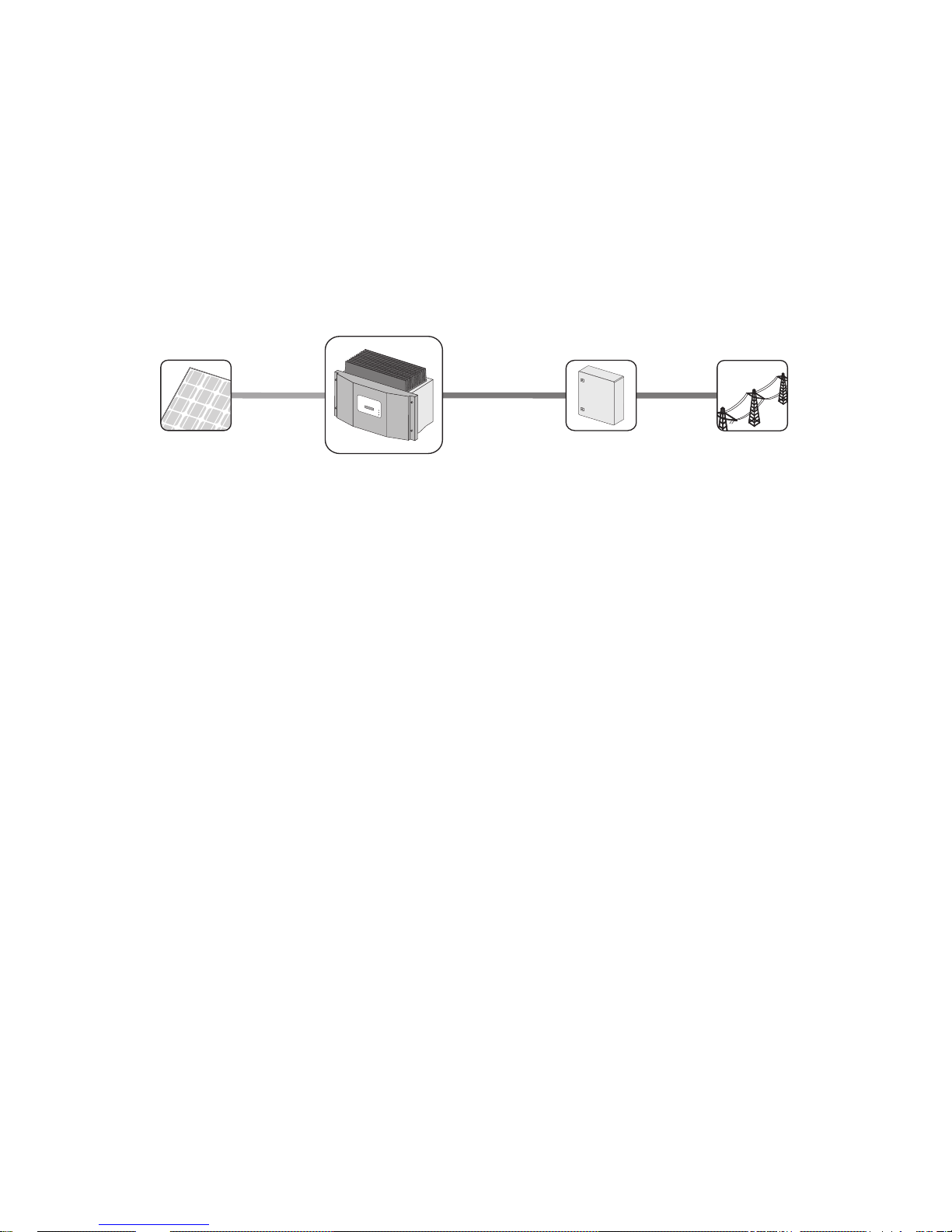
Principle of a PV Plant with this Sunny Boy
The Sunny Boy may only be operated with PV arrays (modules and cabling) of protection class II.
Do not connect any energy sources other than PV modules to the Sunny Boy.
When designing the PV plant, ensure that the values comply with the permitted operating range of all
components at all times. The free design program "Sunny Design" (www.SMA.de/en/SunnyDesign)
will assist you. The manufacturer of the PV modules must have approved the modules for use with this
Sunny Boy device. You must also ensure that all measures recommended by the module manufacturer
regarding long-term maintenance of the module properties are taken (see also Technical Information
"Module Technology" in the download area of www.SMA.de/en).
Do not use the Sunny Boy for purposes other than those described here. Alternative uses,
modifications to the Sunny Boy or the installation of component parts not expressly recommended or
sold by SMA Solar Technology AG shall void any warranty claims and the operation permission.
Public grid
PV modules
Sunny Boy
Distribution
Safety SMA Solar Technology AG
10 SB25-30-IA-en-51 Installation Manual
2.2 Safety Precautions
DANGER!
Danger to life due to high voltages in the inverter
• All work on the inverter may only be carried out by an electrically qualified person.
CAUTION!
Risk of burns due to hot enclosure parts
• Do not touch the enclosure during operation.
• Only touch the lid during operation.
WARNING!
Risk of electric shock when pulling out the DC connectors under load
If you disconnect the DC connectors from the inverter under load, an electric arc may
occur, leading to electric shock and burns.
• If the inverter is not equipped with an Electronic Solar Switch and the regulations
valid at the installation site require an external DC switch-disconnector, install an
external DC switch-disconnector.
• Switch off the AC miniature circuit-breaker and disconnect the inverter on the DC side
before pulling out the DC connectors.
NOTICE!
Dust and water intrusion can damage the inverter.
If the inverter is equipped with an Electronic Solar Switch, it will only provide IP21 degree
of protection once the Electronic Solar Switch has been pulled out. The inverter is therefore
no longer protected against water and dust intrusion. In order to also maintain degree of
protection IP65 during temporary decommissioning, proceed as follows:
• Unlock and disconnect all DC connectors.
• Open all DC connectors and remove the cables.
• Close all DC inputs with the corresponding DC connectors and the supplied sealing
plugs.
• If an Electronic Solar Switch is installed, reattach the Electronic Solar Switch firmly.
SMA Solar Technology AG Safety
Installation Manual SB25-30-IA-en-51 11
NOTICE!
Damage to the inverter due to moisture and dust intrusion
If the Electronic Solar Switch is not plugged in or incorrectly plugged in during operation,
moisture and dust can penetrate the inverter.
If the Electronic Solar Switch is not correctly plugged in, this can cause contacts to wear in
the Electronic Solar Switch or the Electronic Solar Switch might fall down. This can result in
yield loss and damage to the Electronic Solar Switch.
Always plug in the Electronic Solar Switch as described in the following:
• Do not tighten the screw in the Electronic Solar Switch.
• Firmly plug in the Electronic Solar Switch until it is flush with the enclosure.
• Ensure that the maximum distance between the Electronic Solar Switch and the
enclosure is 1 mm.
PV array earthing
Comply with local regulations when earthing the modules and the PV array.
SMA Solar Technology AG recommends connecting the array frame and other electrically
conductive surfaces so that there is continuous conduction and to earth them in order to
ensure maximum protection for installations and persons.
Safety SMA Solar Technology AG
12 SB25-30-IA-en-51 Installation Manual
2.3 Explanation of Symbols
This section gives an explanation of all the symbols found on the inverter and on the type label.
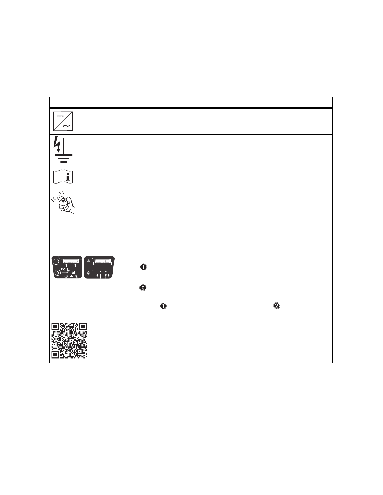
2.3.1 Symbols on the Inverter
* This function is valid from firmware version 4.00, not for SB 2500-IT/3000-IT
** Optional
*** QR-Code is a registered trademark of DENSO WAVE INCORPORATED.
Symbol Explanation
Operation display
Indicates the operating state of the inverter.
Ground fault or varistor defective
Read Section 9.3 "Red LED is Permanently Lit" (page55).
Error or fault
Read Section 9 "Troubleshooting" (page51).
You can operate the display by tapping on the enclosure lid:
• Tapping once: the backlight switches on or the display scrolls to the
next display message.
• Tapping twice in quick succession*: the inverter shows the display
messages from the startup phase again (see Section 6.2 "Display
Messages during the Startup Phase" (page38)).
DC switch-disconnector Electronic Solar Switch (ESS)**
• When the Electronic Solar Switch is plugged in, the electric DC
circuit is closed.
• To interrupt the electric DC circuit and disconnect the inverter
securely under load, you have to first pull out the Electronic Solar
Switch and then remove all DC connectors as described in
Section 7.2 "Opening the Inverter" (page44).
QR-Code
®
*** for SMA bonus program
You will find information on the SMA bonus programme at
www.SMA-Bonus.com.
SMA Solar Technology AG Safety
Installation Manual SB25-30-IA-en-51 13
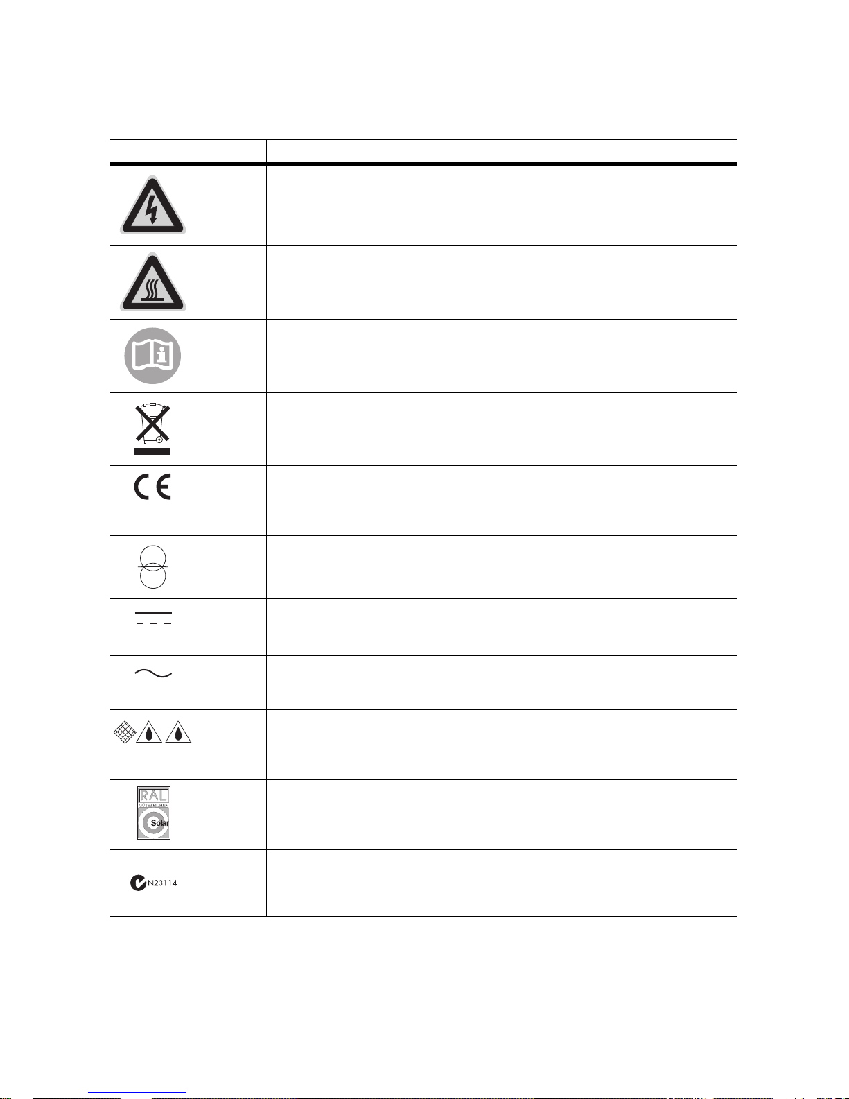
2.3.2 Symbols on the Type Label
Symbol Explanation
Beware of hazardous voltage.
The inverter operates at high voltages. All work on the inverter may only be
carried out by an electrically qualified person.
Beware of hot surface.
The inverter can become hot during operation. Avoid contact during
operation.
Observe all documentation that accompanies the inverter.
The inverter must not be disposed of together with the household waste. For
more information on disposal, see Section 10.4 "Disposing of the Inverter"
(page61).
CE marking
The inverter complies with the requirements of the applicable EC
guidelines.
The inverter has a transformer
Direct current (DC)
Alternating current (AC)
Degree of protection IP65
The inverter is protected against dust intrusion and water jets from any
angle.
RAL quality mark for solar products
The inverter complies with the requirements of the German Institute for
Quality Assurance and Labeling.
Australian mark of conformity
Unpacking SMA Solar Technology AG
14 SB25-30-IA-en-51 Installation Manual
3 Unpacking
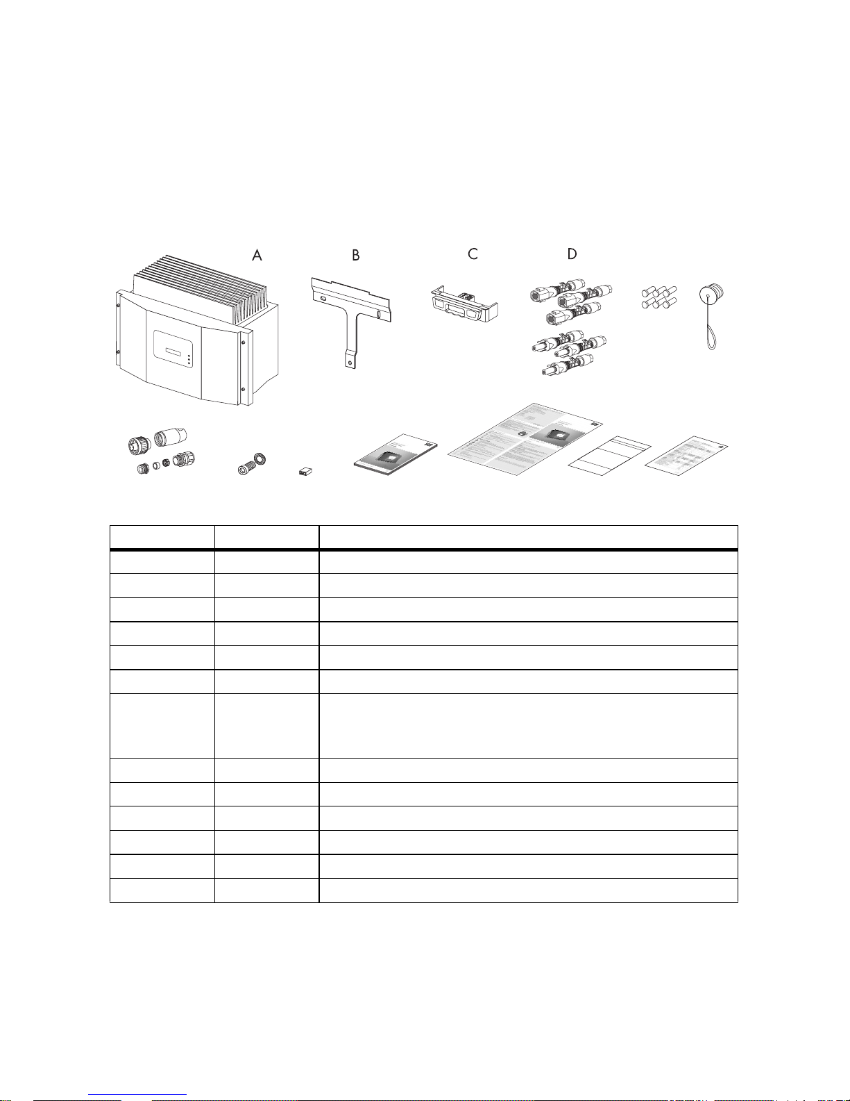
3.1 Scope of Delivery
Check the delivery for completeness and for any visible external damage. Contact your specialty
retailer if anything is damaged or missing.
* Optional
** For inverters without ESS: 1 x positive, 1 x negative
*** For inverters without ESS: 2 sealing plugs
Object Quantity Description
A 1Sunny Boy
B 1 Wall mounting bracket
C 1 Electronic Solar Switch (ESS)*
D 6 (2) DC connector (3 x positive, 3 x negative)**
E 6 (2) Sealing plug for DC connectors***
F 1 Protective cap for AC jack on inverter
G 1 AC connection socket: jack element, threaded sleeve,
PG13.5 pressure screw, PG13.5 sealing ring,
PG13.5 fastening case, PG16 cable gland
H 1 M6x12 cheese-head screw and conical spring washer
I 1Jumper
K 1 Installation manual
L 1 User manual
M 1 Document set with explanations and certificates
N 1 Supplementary sheet with inverter default settings
(
N
a
m
e
d
e
s
G
e
rä
t
e
s
)
:
B
it
te
f
ü
lle
n
S
ie
d
ie
f
o
lg
e
n
d
e
n
F
e
ld
e
r
a
u
s
:
(Name des Gerätes):
Bitte füllen Sie die folgenden Felder aus:
:
Ty
p
:
S
e
r
i
e
n
n
u
m
m
e
r
:
D
a
t
u
m
d
e
r
I
n
b
e
t
r
i
e
b
n
a
h
m
e
:
A
n
s
c
h
r
i
f
t
:
I
n
s
t
a
l
l
a
t
i
o
n
s
b
e
t
r
i
e
b
Typ:
Seriennummer:
Datum der Inbetriebnahme:
Anschrift:
Installationsbetrieb
Ty
p
:
S
e
r
i
e
n
n
u
m
m
e
r
:
D
a
t
u
m
d
e
r
I
n
b
e
t
r
i
e
b
n
a
h
m
e
:
A
n
s
c
h
r
i
f
t
:
I
n
s
t
a
l
l
a
t
i
o
n
s
b
e
t
r
i
e
b
Typ:
Seriennummer:
Datum der Inbetriebnahme:
Anschrift:
Installationsbetrieb
G
e
w
ä
h
r
le
i
s
tu
n
g
s
-
u
n
d
G
a
r
a
n
t
ie
b
e
d
in
g
u
n
g
e
n
Gewährleistungs- und Garantiebedingungen
F
GH
I
K
L
MN
E
+
+
+
_
_
_

SMA Solar Technology AG Unpacking
Installation Manual SB25-30-IA-en-51 15
3.2 Identifying the Inverter
You can identify the inverter using the type label. The type label is on the right-hand side of the
enclosure.
The serial number (Serial No.) and the type (Type/Model) of the inverter, as well as device-specific
characteristics are specified on the type label.
Mounting SMA Solar Technology AG
16 SB25-30-IA-en-51 Installation Manual
4 Mounting
4.1 Safety
4.2 Selecting the Mounting Location
Consider the following requirements when selecting the mounting location:
• The mounting method and location must be suitable for the inverter's weight and dimensions
(see Section 11 "Technical Data" (page62)).
• Mount on a solid surface.
• The mounting location must at all times be clear and safely accessible without the use of
additional aids such as scaffolding or lifting platforms. Non-fulfillment of these criteria may
restrict servicing.
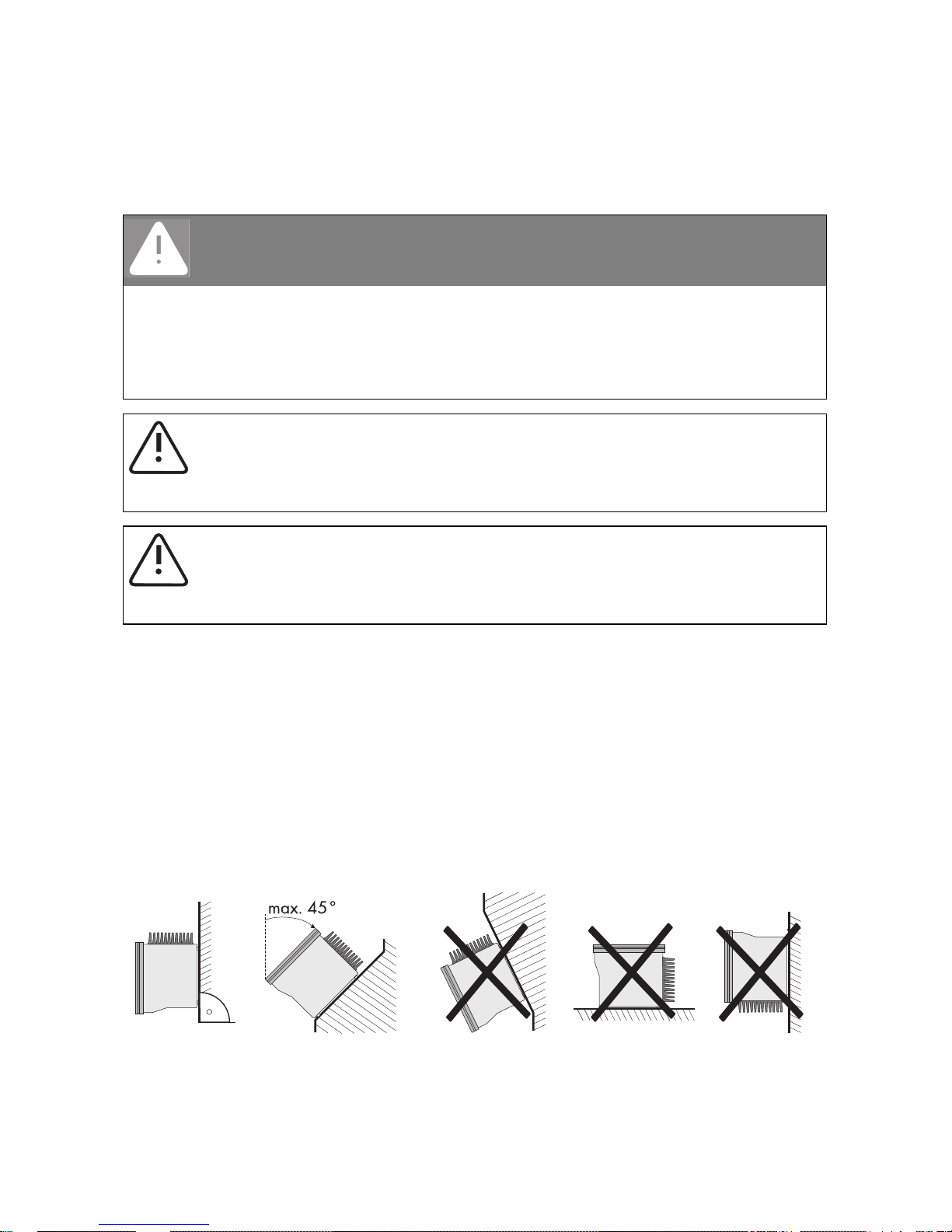
• Mount vertically or tilted backwards by max. 45°.
DANGER!
Danger to life due to fire or explosion
Despite careful construction, electrical devices can cause fires.
• Do not mount the inverter on flammable construction materials.
• Do not mount the inverter in areas where highly flammable materials are stored.
• Do not mount the inverter in a potentially explosive atmosphere.
CAUTION!
Risk of burns due to hot enclosure parts
• Mount the inverter in such a way that the enclosure cannot be touched inadvertently.
CAUTION!
Risk of injury due to the heavy weight of the inverter
• Take the inverter's weight of approx. 32 kg into account for mounting.
SMA Solar Technology AG Mounting
Installation Manual SB25-30-IA-en-51 17
• The connection area must point downward.
• Never mount the device with a forward tilt.
• Never mount the device with a sideways tilt.
• Do not mount horizontally.
• Install at eye level in order to allow operating states to be read at all times.
• To ensure optimal operation, the ambient temperature should be below 40°C.
• Do not expose the inverter to direct solar irradiation as this can cause excessive heating and
thus power reduction.
• In a living area, do not mount the unit on plasterboard walls (or similar) in order to avoid audible
vibrations. When in use, the inverter emits noises which may be perceived as a nuisance in a
living area.
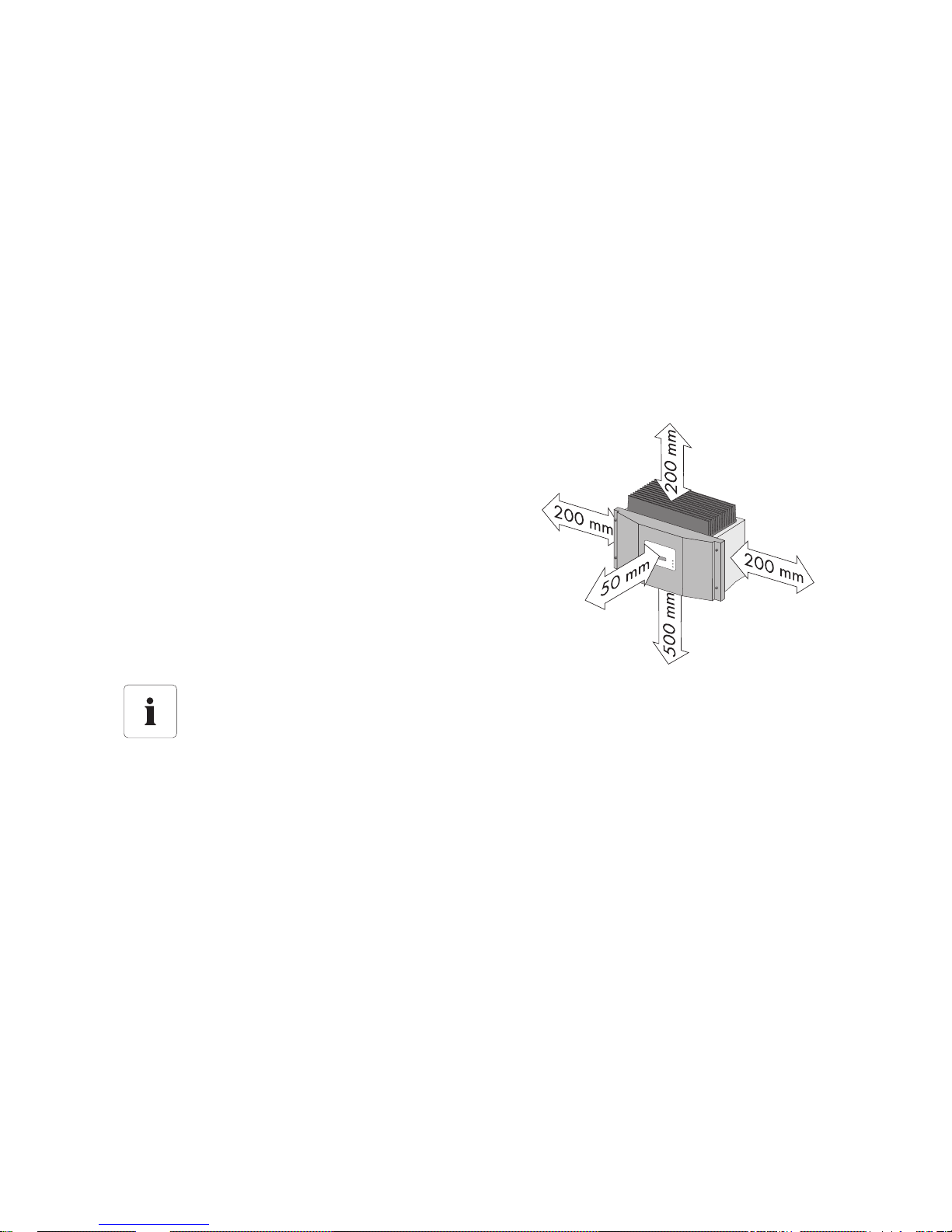
• Observe the minimum clearances to walls, other
inverters or objects as shown in the diagram in
order to ensure sufficient heat dissipation and
sufficient space for removing the Electronic Solar
Switch.
Multiple inverters installed in areas with high ambient temperatures
If necessary, increase the clearance spaces and make sure there is enough fresh-air supply
to ensure sufficient cooling of the inverters.
Mounting SMA Solar Technology AG
18 SB25-30-IA-en-51 Installation Manual
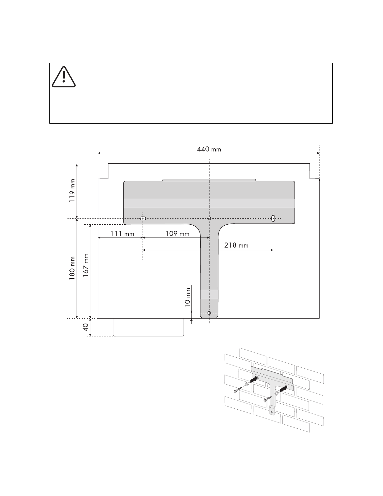
4.3 Mounting the Inverter with the Wall Mounting Bracket
1. Use the wall mounting bracket as a drilling template and mark the positions of the drill holes.
2. Attach the wall mounting bracket to the wall using
appropriate screws and washers.
CAUTION!
Risk of injury due to the heavy weight of the inverter
• Take the inverter's weight of approx. 32 kg into account for mounting.
• Use mounting material suitable for the surface when attaching the wall mounting
bracket.

SMA Solar Technology AG Mounting
Installation Manual SB25-30-IA-en-51 19
3. Mount the inverter with its upper anchorage
bracket on the wall mounting bracket in such a way
that it cannot slide out of the bracket sideways.
4. If a second protective conductor is required in the
country of installation, earth the inverter and fix it
securely as described in Section 5.2.3 "Connecting
Additional Earthing" (page27).
5. If a second protective conductor is not required, fix
the inverter securely using the enclosed M6x12
screw.
6. Check to ensure that the inverter is securely in place.
☑The inverter is mounted to the wall.
Electrical Connection SMA Solar Technology AG
20 SB25-30-IA-en-51 Installation Manual
5 Electrical Connection
5.1 Overview of the Connection Area
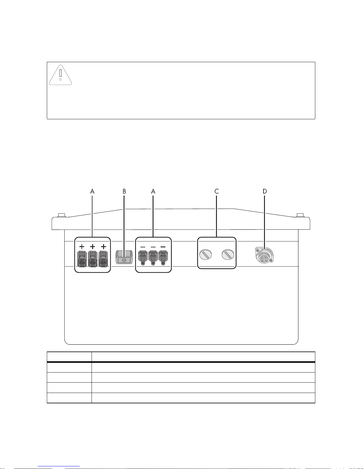
5.1.1 Exterior View
The following figure shows the assignment of the individual connection areas on the bottom of the
inverter.
* If you have ordered the inverter without ESS, the inverter is equipped with 1 negative and 1 positive DC connector.
** Optional
NOTICE!
Electrostatic discharges can damage the inverter.
Internal component parts of the inverter can be irreparably damaged by static electric
discharge.
• Earth yourself before touching a component part.
Object Description
A DC connectors for connecting the PV strings*
B Jack for connecting the DC switch-disconnector Electronic Solar Switch (ESS)**
C Enclosure opening with filler-plugs for communication
D Jack for AC connection
SMA Solar Technology AG Electrical Connection
Installation Manual SB25-30-IA-en-51 21
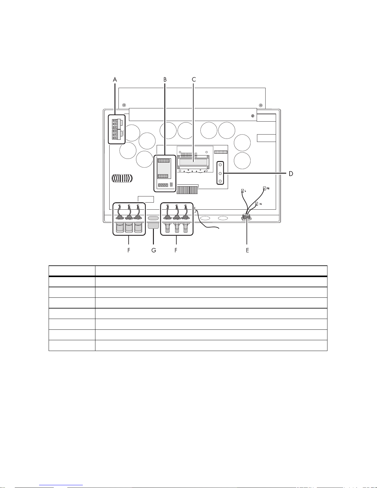
5.1.2 Interior View
The following figure shows the various components and connection areas of the open inverter.
* If you have ordered the inverter without ESS, the inverter is equipped with 1 negative and 1 positive DC connector.
** Optional
Object Description
A Varistors
B Connection area and slots for optional communication via RS485
C Display
D Operating status LEDs
E Jack for AC connection
F DC connector*
G Jack for the Electronic Solar Switch (ESS)**
Electrical Connection SMA Solar Technology AG
22 SB25-30-IA-en-51 Installation Manual
5.2 Connection to the Power Distribution Mains (AC)
5.2.1 Conditions for the AC Connection
Cable dimensioning
Use Sunny Design version 2.0 or higher for dimensioning the conductor cross-sectional areas
(see Sunny Design programme at www.SMA.de/en).
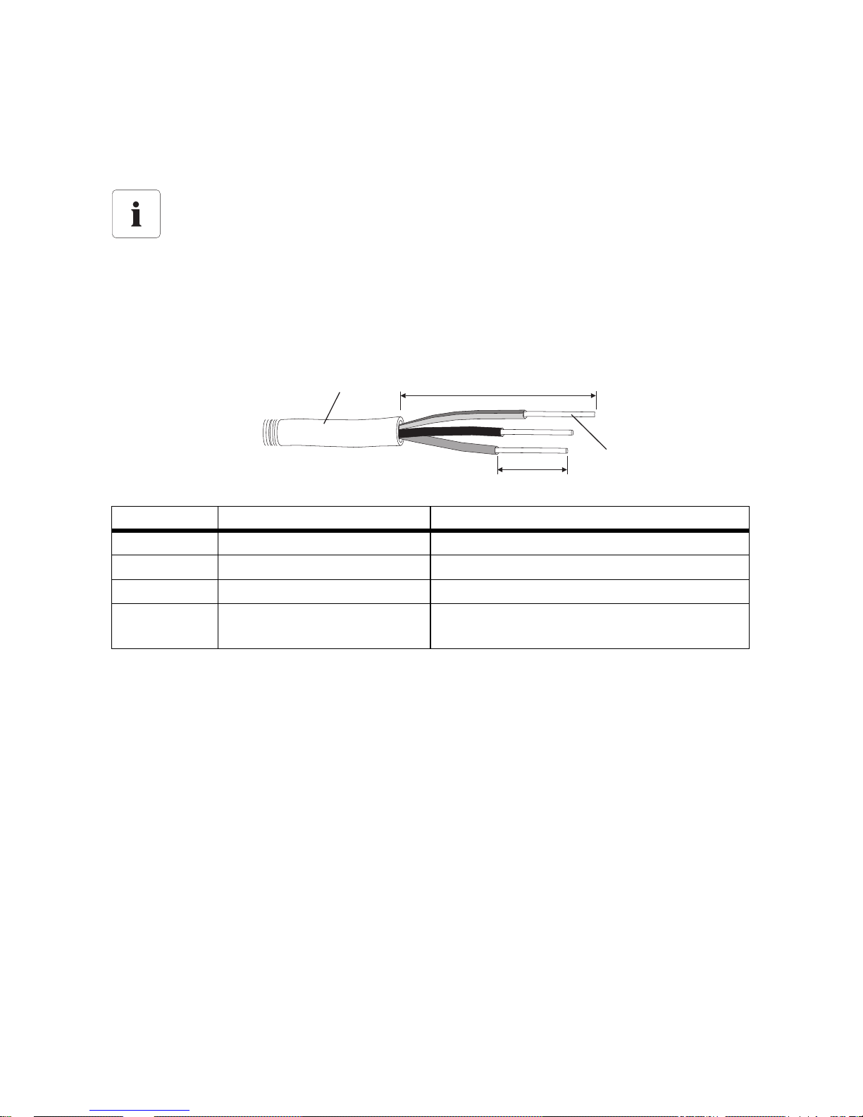
Cable requirements
Connection requirements of the network operator
Comply with the connection requirements of your network operator.
Position Designation Value
A External diameter 9 mm … 17 mm
B Stripping length 30 mm
C Conductor cross-section Max. 2.5 mm²
D Length of insulation to be
stripped off
4mm…5mm
D
B
A
C
SMA Solar Technology AG Electrical Connection
Installation Manual SB25-30-IA-en-51 23
Load Disconnection Unit
You must install a separate miniature circuit-breaker for each inverter in order to ensure that the
inverter can be securely disconnected under load. The maximum permissible fuse protection can be
found in Section 11 "Technical Data" (page62).
Detailed information and examples for the rating of a miniature circuit-breaker can be found in the
Technical Information "Miniature Circuit-breaker" in the SMA Solar Technology AG download area
at www.SMA.de/en.
DANGER!
Danger to life due to fire
When more than 1 inverter is connected in parallel to the same miniature circuit-breaker,
the protective function of the miniature circuit-breaker is no longer guaranteed. It can result
in a cable fire or destruction of the inverter.
• Never connect several inverters to a single miniature circuit-breaker.
• Observe the maximum permissible fuse protection of the inverter when selecting the
miniature circuit-breaker.
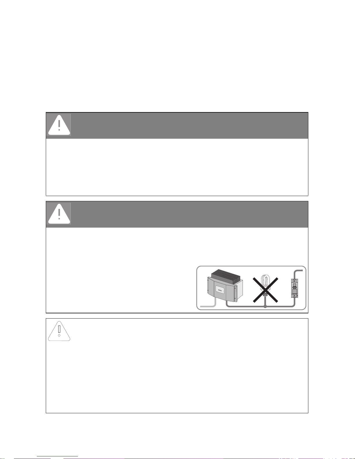
DANGER!
Danger to life due to fire
When a generator (inverter) and a load are connected to the same miniature circuitbreaker, the protective function of the miniature circuit-breaker is no longer guaranteed.
The currents from the inverter and the mains can accumulate to overcurrents that are not
detected by the miniature circuit-breaker.
• Never connect loads between the
inverter and the miniature circuitbreaker without protection.
• Always protect loads separately.
NOTICE!
Damage to the inverter by using screw type fuse elements as a load
disconnection unit
A screw type fuse element, e.g. DIAZED fuse or NEOZED fuse, is not a switch-disconnector,
and thus may not be used as a load disconnection unit. A screw type fuse element serves
as cable protection only.
When disconnecting under load using a screw type fuse element, the inverter can be
damaged.
• Use only a switch-disconnector or a miniature circuit-breaker as a load disconnection
unit.
 Loading...