

SUNNY BOY 2500TL Single Tracker,SUNNY BOY 3000TL Single Tracker,SUNNY BOY 2500TL Single Tracker,SUNNY BOY 3000TL Single Tracker
SMA SUNNY BOY 2500TL Single Tracker,SUNNY BOY 3000TL Single Tracker,SUNNY BOY 2500TL Single Tracker,SUNNY BOY 3000TL Single Tracker Installation Manual
SB25_30TLST_21-IA-IEN121110 | IMEN-SBTLST-21 | Version 1.0
EN
PV Inverter
SUNNY BOY 2500TLSingleTracker
SUNNYBOY3000TLSingleTracker
Installation Manual


SMA Solar Technology AG Table of Contents
Installation Manual SB25_30TLST_21-IA-IEN121110 3
Table of Contents
1 Information on this Document. . . . . . . . . . . . . . . . . . . . . . . 7
1.1 Validity . . . . . . . . . . . . . . . . . . . . . . . . . . . . . . . . . . . . . . . . . . . . 7
1.2 Target Audience . . . . . . . . . . . . . . . . . . . . . . . . . . . . . . . . . . . . . 7
1.3 Additional Information . . . . . . . . . . . . . . . . . . . . . . . . . . . . . . . . 7
1.4 Symbols Used . . . . . . . . . . . . . . . . . . . . . . . . . . . . . . . . . . . . . . . 8
2 Safety . . . . . . . . . . . . . . . . . . . . . . . . . . . . . . . . . . . . . . . . . 10
2.1 Intended Use. . . . . . . . . . . . . . . . . . . . . . . . . . . . . . . . . . . . . . . 10
2.2 Qualification of Skilled Persons . . . . . . . . . . . . . . . . . . . . . . . . 11
2.3 Safety Precautions. . . . . . . . . . . . . . . . . . . . . . . . . . . . . . . . . . . 12
3 Scope of Delivery. . . . . . . . . . . . . . . . . . . . . . . . . . . . . . . . 14
4 Product Description . . . . . . . . . . . . . . . . . . . . . . . . . . . . . . 15
4.1 Sunny Boy. . . . . . . . . . . . . . . . . . . . . . . . . . . . . . . . . . . . . . . . . 15
4.2 Symbols on the Inverter. . . . . . . . . . . . . . . . . . . . . . . . . . . . . . . 16
4.3 Type Label . . . . . . . . . . . . . . . . . . . . . . . . . . . . . . . . . . . . . . . . 17
4.4 Display . . . . . . . . . . . . . . . . . . . . . . . . . . . . . . . . . . . . . . . . . . . 19
4.5 Electronic Solar Switch . . . . . . . . . . . . . . . . . . . . . . . . . . . . . . . 22
4.6 Communication. . . . . . . . . . . . . . . . . . . . . . . . . . . . . . . . . . . . . 23
4.7 Multi-Function Relay . . . . . . . . . . . . . . . . . . . . . . . . . . . . . . . . . 23
4.8 Grid Management . . . . . . . . . . . . . . . . . . . . . . . . . . . . . . . . . . 24
4.9 Varistors . . . . . . . . . . . . . . . . . . . . . . . . . . . . . . . . . . . . . . . . . . 24
5 Mounting. . . . . . . . . . . . . . . . . . . . . . . . . . . . . . . . . . . . . . . 25
5.1 Safety . . . . . . . . . . . . . . . . . . . . . . . . . . . . . . . . . . . . . . . . . . . . 25
5.2 Selecting the Mounting Location. . . . . . . . . . . . . . . . . . . . . . . . 25
5.3 Mounting the Inverter . . . . . . . . . . . . . . . . . . . . . . . . . . . . . . . . 27

Table of Contents SMA Solar Technology AG
4 SB25_30TLST_21-IA-IEN121110 Installation Manual
6 Electrical Connection . . . . . . . . . . . . . . . . . . . . . . . . . . . . . 30
6.1 Safety . . . . . . . . . . . . . . . . . . . . . . . . . . . . . . . . . . . . . . . . . . . . 30
6.2 Overview of the Connection Area . . . . . . . . . . . . . . . . . . . . . . 30
6.3 Connection to the Electricity Grid (AC). . . . . . . . . . . . . . . . . . . 32
6.3.1 Conditions for the AC Connection . . . . . . . . . . . . . . . . . . . . . . . . . . . . . . . . 32
6.3.2 Connecting the Inverter to the Electricity Grid (AC) . . . . . . . . . . . . . . . . . . . 35
6.3.3 Additional Earthing of the Enclosure . . . . . . . . . . . . . . . . . . . . . . . . . . . . . . . 38
6.4 Connecting the PV Array (DC) . . . . . . . . . . . . . . . . . . . . . . . . . 38
6.4.1 Conditions for the DC connection . . . . . . . . . . . . . . . . . . . . . . . . . . . . . . . . . 38
6.4.2 Assembling the DC Connectors. . . . . . . . . . . . . . . . . . . . . . . . . . . . . . . . . . . 39
6.4.3 Opening the DC Connector . . . . . . . . . . . . . . . . . . . . . . . . . . . . . . . . . . . . . 41
6.4.4 Connecting the PV Array (DC) . . . . . . . . . . . . . . . . . . . . . . . . . . . . . . . . . . . 42
6.5 Setting the Country Standard and Display Language . . . . . . . 46
6.5.1 Checking the Country Standard . . . . . . . . . . . . . . . . . . . . . . . . . . . . . . . . . . 48
6.5.2 Setting the Country Standard and Language using the
Rotary Switch . . . . . . . . . . . . . . . . . . . . . . . . . . . . . . . . . . . . . . . . . . . . . . . . 51
6.6 Communication. . . . . . . . . . . . . . . . . . . . . . . . . . . . . . . . . . . . . 52
6.6.1 Interface for RS485 Communication. . . . . . . . . . . . . . . . . . . . . . . . . . . . . . . 52
6.6.2 Setting the Bluetooth NetID . . . . . . . . . . . . . . . . . . . . . . . . . . . . . . . . . . . . . 53
6.6.3 Multi-Function Relay . . . . . . . . . . . . . . . . . . . . . . . . . . . . . . . . . . . . . . . . . . . 53
7 Commissioning . . . . . . . . . . . . . . . . . . . . . . . . . . . . . . . . . . 54
7.1 Commissioning the Inverter. . . . . . . . . . . . . . . . . . . . . . . . . . . . 54
7.2 Display Messages during the Start Phase. . . . . . . . . . . . . . . . . 55
7.3 Self-test in Accordance with ENEL Guideline (Only for Italy) . . 56
7.3.1 Starting the Self-Test . . . . . . . . . . . . . . . . . . . . . . . . . . . . . . . . . . . . . . . . . . . 56
7.3.2 Test Sequence . . . . . . . . . . . . . . . . . . . . . . . . . . . . . . . . . . . . . . . . . . . . . . . . 57
7.3.3 Aborting the Self-Test. . . . . . . . . . . . . . . . . . . . . . . . . . . . . . . . . . . . . . . . . . . 60
7.3.4 Restarting the Self-Test. . . . . . . . . . . . . . . . . . . . . . . . . . . . . . . . . . . . . . . . . . 60

SMA Solar Technology AG Table of Contents
Installation Manual SB25_30TLST_21-IA-IEN121110 5
8 Opening and Closing. . . . . . . . . . . . . . . . . . . . . . . . . . . . . 61
8.1 Safety . . . . . . . . . . . . . . . . . . . . . . . . . . . . . . . . . . . . . . . . . . . . 61
8.2 Disconnecting the Inverter from Voltage Sources . . . . . . . . . . . 62
8.3 Closing the Inverter. . . . . . . . . . . . . . . . . . . . . . . . . . . . . . . . . . 65
9 Maintenance and Cleaning. . . . . . . . . . . . . . . . . . . . . . . . 67
9.1 Cleaning the Inverter. . . . . . . . . . . . . . . . . . . . . . . . . . . . . . . . . 67
9.2 Checking Heat Dissipation . . . . . . . . . . . . . . . . . . . . . . . . . . . . 67
9.3 Checking the Electronic Solar Switch for Wear . . . . . . . . . . . . 68
10 Slot for SD Card . . . . . . . . . . . . . . . . . . . . . . . . . . . . . . . . . 69
11 Troubleshooting . . . . . . . . . . . . . . . . . . . . . . . . . . . . . . . . . 70
11.1 LED Signals . . . . . . . . . . . . . . . . . . . . . . . . . . . . . . . . . . . . . . . . 70
11.2 Event Messages . . . . . . . . . . . . . . . . . . . . . . . . . . . . . . . . . . . . 71
11.3 Error Messages. . . . . . . . . . . . . . . . . . . . . . . . . . . . . . . . . . . . . 72
11.4 DC Current after AC-side Disconnection. . . . . . . . . . . . . . . . . . 82
11.5 Checking the PV Array for Earth Faults . . . . . . . . . . . . . . . . . . . 82
11.6 Checking the Function of the Varistors . . . . . . . . . . . . . . . . . . . 84
12 Decommissioning . . . . . . . . . . . . . . . . . . . . . . . . . . . . . . . . 88
12.1 Disassembling the Inverter . . . . . . . . . . . . . . . . . . . . . . . . . . . . 88
12.2 Replacing the Enclosure Lid . . . . . . . . . . . . . . . . . . . . . . . . . . . 88
12.3 Packing the Inverter. . . . . . . . . . . . . . . . . . . . . . . . . . . . . . . . . . 91
12.4 Storing the Inverter . . . . . . . . . . . . . . . . . . . . . . . . . . . . . . . . . . 91
12.5 Disposing of the Inverter . . . . . . . . . . . . . . . . . . . . . . . . . . . . . . 91
13 Technical Data . . . . . . . . . . . . . . . . . . . . . . . . . . . . . . . . . . 92
13.1 DC/AC . . . . . . . . . . . . . . . . . . . . . . . . . . . . . . . . . . . . . . . . . . . 92
13.1.1 Sunny Boy 2500TL Single Tracker . . . . . . . . . . . . . . . . . . . . . . . . . . . . . . . . 92
13.1.2 Sunny Boy 3000TL Single Tracker . . . . . . . . . . . . . . . . . . . . . . . . . . . . . . . . 93
13.2 General Data . . . . . . . . . . . . . . . . . . . . . . . . . . . . . . . . . . . . . . 94

Table of Contents SMA Solar Technology AG
6 SB25_30TLST_21-IA-IEN121110 Installation Manual
13.3 Protective Devices . . . . . . . . . . . . . . . . . . . . . . . . . . . . . . . . . . . 95
13.4 Approvals . . . . . . . . . . . . . . . . . . . . . . . . . . . . . . . . . . . . . . . . . 95
13.5 Climatic Conditions. . . . . . . . . . . . . . . . . . . . . . . . . . . . . . . . . . 96
13.6 Features . . . . . . . . . . . . . . . . . . . . . . . . . . . . . . . . . . . . . . . . . . 96
13.7 Electronic Solar Switch . . . . . . . . . . . . . . . . . . . . . . . . . . . . . . . 96
13.8 Torques . . . . . . . . . . . . . . . . . . . . . . . . . . . . . . . . . . . . . . . . . . . 96
13.9 Earthing Systems. . . . . . . . . . . . . . . . . . . . . . . . . . . . . . . . . . . . 97
13.10 Data Storage Capacity. . . . . . . . . . . . . . . . . . . . . . . . . . . . . . . 97
14 Accessories . . . . . . . . . . . . . . . . . . . . . . . . . . . . . . . . . . . . . 98
15 Contact . . . . . . . . . . . . . . . . . . . . . . . . . . . . . . . . . . . . . . . . 99
SMA Solar Technology AG Information on this Document
Installation Manual SB25_30TLST_21-IA-IEN121110 7
1 Information on this Document
1.1 Validity
This document is valid for the following device types:
• SB 2500TLST-21
• SB 3000TLST-21
1.2 Target Audience
This document is for skilled workers. Only skilled workers are allowed to perform the tasks set forth in
this document (see Section 2.2"Qualification of Skilled Persons" (page11)).
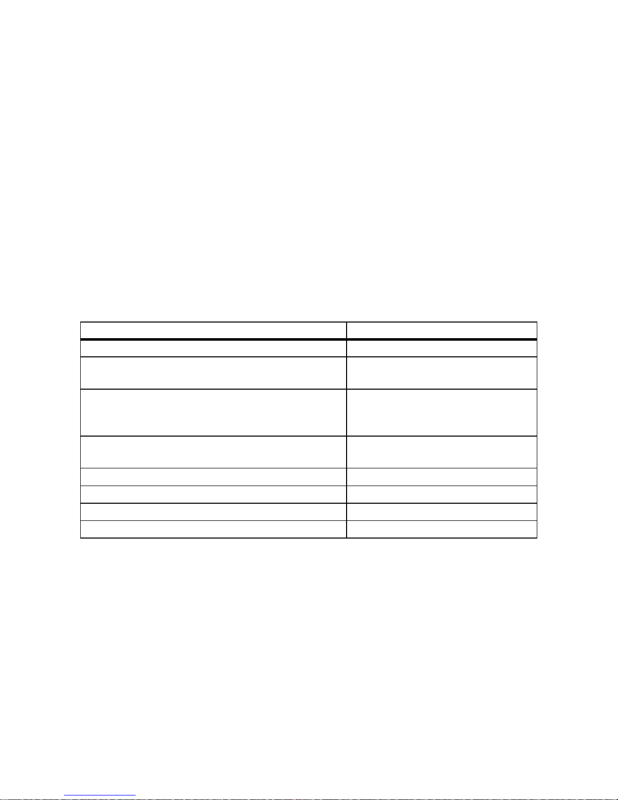
1.3 Additional Information
Additional information is available at www.SMA.de/en.
Title Document type
Miniature Circuit-breaker Technical information
Measured Values, Operating Parameters, and Event
Messages.
Technical description
Parameter Settings ‒
SUNNY BOY 2500TL / 3000TL Single Tracker
SUNNY BOY 3000TL / 3600TL / 4000TL / 5000TL
Technical description
SMA Bluetooth ‒ SMA Bluetooth
®
Wireless Technology
in Practice
Technical information
SMA Bluetooth
®
Wireless Technology Technical description
Multi-functional relay and OptiTrac Global Peak Technical description
Module Technology Technical information
Capacitive Discharge Currents Technical information
Information on this Document SMA Solar Technology AG
8 SB25_30TLST_21-IA-IEN121110 Installation Manual
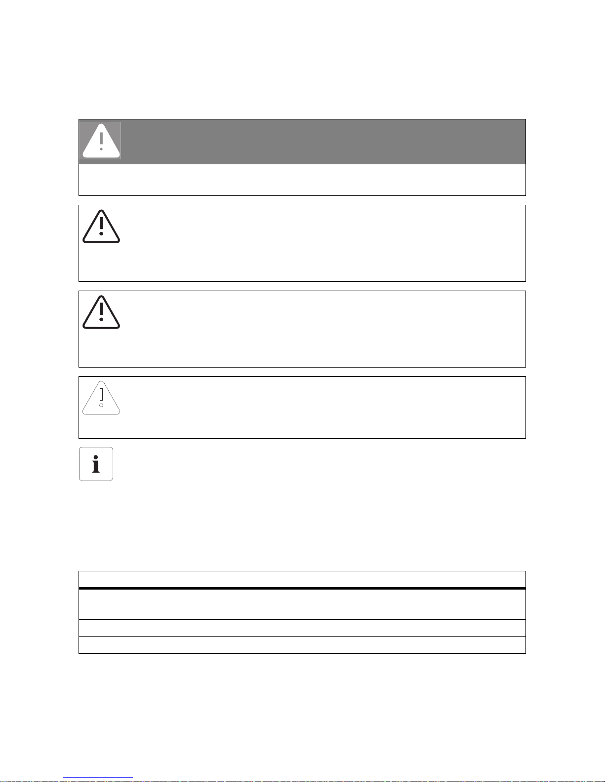
1.4 Symbols Used
The following types of safety precautions and general information appear in this document:
Nomenclature
The following nomenclature is used in this document:
DANGER!
DANGER indicates a hazardous situation which, if not avoided, will result in death or
serious injury.
WARNING!
WARNING indicates a safety precaution which, if not avoided, could result in death or
serious injury.
CAUTION!
CAUTION indicates a hazardous situation which, if not avoided, could result in minor or
moderate injury.
NOTICE!
NOTICE indicates a situation which, if not avoided, could result in property damage.
Information
Information provides tips that are valuable for effective installation and operation of the
product.
☑ This symbol indicates the result of an action.
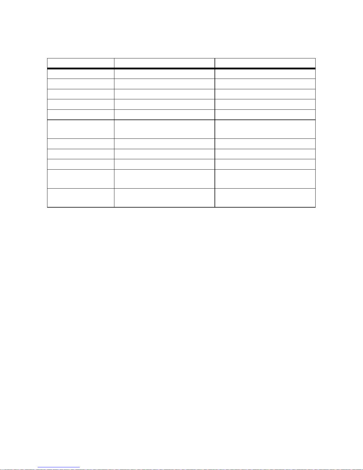
Complete designation Abbreviation in this document
Sunny Boy 2500TL Single Tracker/
Sunny Boy 3000TL Single Tracker
Inverter, product
Electronic Solar Switch ESS
SMA Bluetooth
®
Wireless Technology Bluetooth
SMA Solar Technology AG Information on this Document
Installation Manual SB25_30TLST_21-IA-IEN121110 9
Abbreviations
Abbreviation Designation Explanation
AC Alternating Current DC Direct Current EG European Community LED Light-Emitting Diode MPP Maximum Power Point NetID Network Identification Identification number for
SMA Bluetooth network
MSL Mean Sea Level PE Protective Earth Protective conductor
PV Photovoltaics AF Width Across Flats The distance between two parallel
flat surfaces ("flats") of a screw head.
VDE Verband der Elektrotechnik
Elektronik Informationstechnik e.V.
Association for Electrical, Electronic
and Information Technologies
Safety SMA Solar Technology AG
10 SB25_30TLST_21-IA-IEN121110 Installation Manual
2 Safety
2.1 Intended Use
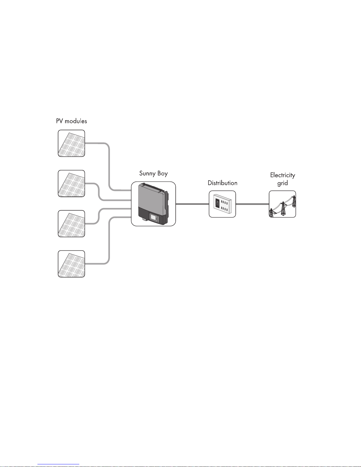
The Sunny Boy is a PV inverter, which converts the direct current of the PV array to grid-compliant
alternating current and feeds it into the electricity grid.
Principle of a PV Plant with this Sunny Boy
The Sunny Boy is suitable for indoor and outdoor use.
The Sunny Boy may only be operated with PV arrays (PV modules and cabling) of protection class II.
The PV modules used must be suitable for use with the Sunny Boy and must be released by the module
manufacturer.
PV modules with large capacities to earth may only be used if their coupling capacity does not exceed
1.4 μF.
All components must remain within their operating ranges at all times.
For safety reasons, it is not permitted to modify the product or install components that are not explicitly
recommended or distributed by SMA Solar Technology AG for this product.
Only use the Sunny Boy in accordance with the information provided in the enclosed documentation.
Any other use can result in personal injury or property damage.
• Do not mount the inverter on flammable construction materials.
• Do not mount the inverter in areas where highly flammable materials are stored.
• Do not mount the inverter in a potentially explosive atmosphere.

SMA Solar Technology AG Safety
Installation Manual SB25_30TLST_21-IA-IEN121110 11
The enclosed documentation is an integral part of this product.
• Read and adhere to the documentation.
• Keep the documentation in a convenient place for future reference.
2.2 Qualification of Skilled Persons
The tasks described in this document are intended for skilled persons only. Skilled persons must have
the following qualifications:
• Knowledge of how an inverter works and is operated
• Training in how to deal with the dangers and risks associated with installing and using electrical
devices and plants
• Training in the installation and commissioning of electrical devices and plants
• Knowledge of all applicable standards and guidelines
• Knowledge of and adherence to this document and all safety precautions
Safety SMA Solar Technology AG
12 SB25_30TLST_21-IA-IEN121110 Installation Manual
2.3 Safety Precautions
DANGER!
Danger to life due to high voltages in the inverter.
High voltages that can result in electric shocks are present in the conductive components
of the inverter.
• Prior to performing any work on the inverter, disconnect the inverter on the AC and
DC sides (see Section 8.2"Disconnecting the Inverter from Voltage Sources"
(page62)).
DANGER!
Risk of burns due to electric arc
To prevent arcing when disconnecting cables in the PV array, the ESS and DC connectors
must be removed from the inverter, or the external DC switch-disconnector must be
switched off and the DC connectors must be removed from the inverter before performing
any work on the PV array.
• Before starting work on the PV array, always disconnect the inverter from the AC and
DC side (see Section 8.2"Disconnecting the Inverter from Voltage Sources"
(page62)).
• Attach the enclosed warning label "Risk of burns from electric arc" so that it is clearly
visible on the external AC disconnection device.
WARNING!
Risk of electric shock when pulling out the DC connectors under load.
If you disconnect the DC connectors from the inverter under load, an electric arc may
occur, causing electric shock and burns.
• If the inverter is not equipped with an Electronic Solar Switch and the regulations in
the country of installation require an external DC switch-disconnector, install an
external DC switch-disconnector.
• Switch off the AC miniature circuit-breaker and disconnect the inverter on the DC side
before pulling out the DC connectors.
CAUTION!
Risk of burns due to hot enclosure parts
Some parts of the enclosure can become hot during operation.
• Only touch the lower enclosure lid of the inverter during operation.
SMA Solar Technology AG Safety
Installation Manual SB25_30TLST_21-IA-IEN121110 13
NOTICE!
Water and dust intrusion can damage the inverter.
If the inverter is not equipped with an ESS, the electronics in the inverter comply with degree
of protection IP65 when closed. If the inverter is equipped with an ESS, the electronics in
the inverter comply with degree of protection IP65 when closed with the ESS attached. The
inverter is then protected against dust and water intrusion. The inverter's connection area
complies with degree of protection IP54. It is protected against dust deposits in the interior
and against splashes of water from all angles.
• If the ESS is not attached, the inverter must be protected against dust and water.
• Attach the ESS again after any work on the inverter.
PV array earthing
Comply with local regulations for the earthing of the modules and the PV array.
SMA Solar Technology AG recommends connecting the array frame and other electrically
conductive surfaces so that there is continuous conduction and earthing them in order to
ensure maximum protection for property and persons.
Scope of Delivery SMA Solar Technology AG
14 SB25_30TLST_21-IA-IEN121110 Installation Manual
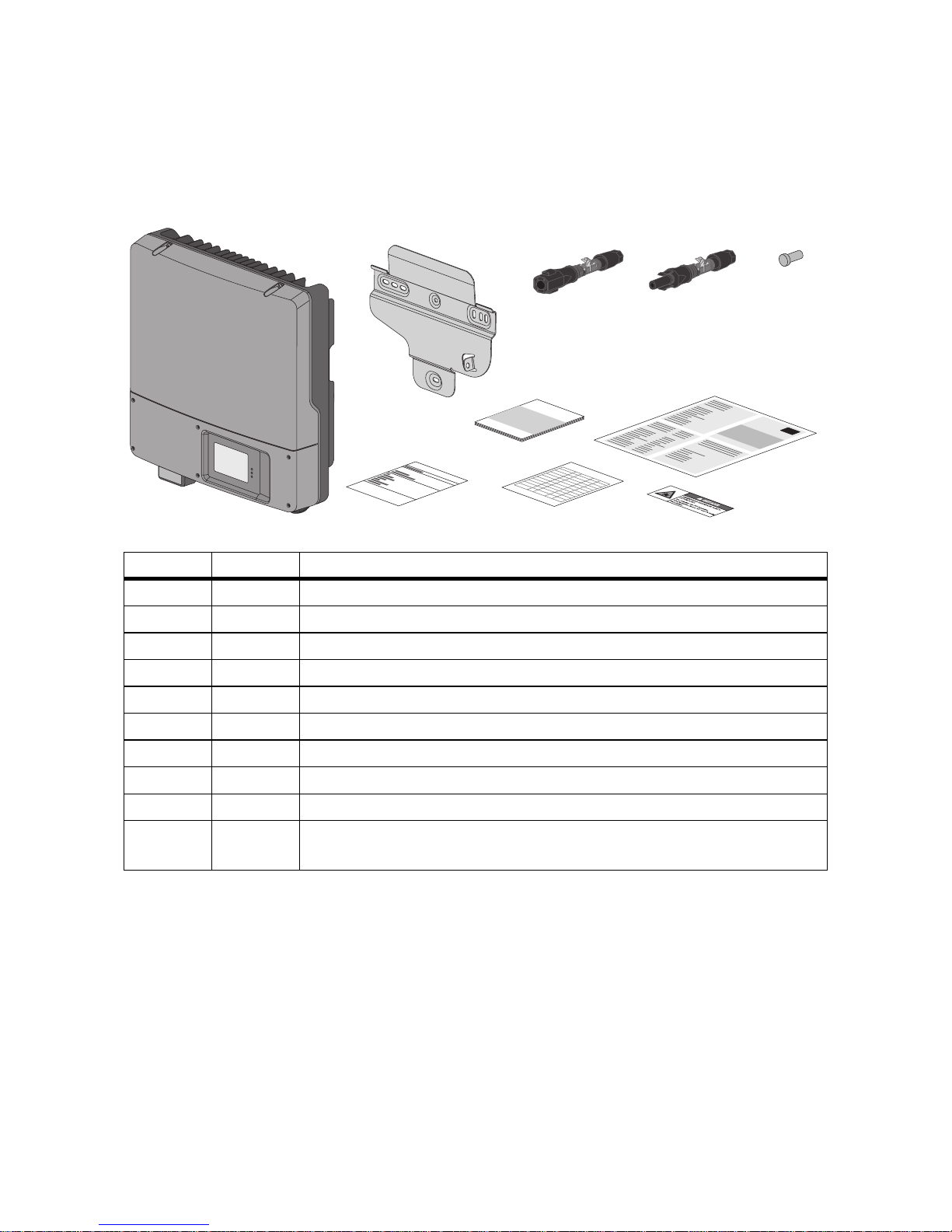
3 Scope of Delivery
Check the delivery for completeness and any externally visible damage. Contact your dealer if the
delivery is incomplete or you find any damage.
Object Quantity Description
A 1 Sunny Boy
B 1 Wall mounting bracket
C 2 Positive DC connector
D 2 Negative DC connector
E 4 Sealing plugs for the DC connectors
F 1 Installation manual
G 1User manual
H 1 Document set with explanations and certificates
I 1 Supplementary sheet with inverter default settings
K 1 Warning label "Risk of burns from electric arc" for the disconnection device
on the AC side.
A
B
C
E
H
FG
I
K
_
+
D
SMA Solar Technology AG Product Description
Installation Manual SB25_30TLST_21-IA-IEN121110 15
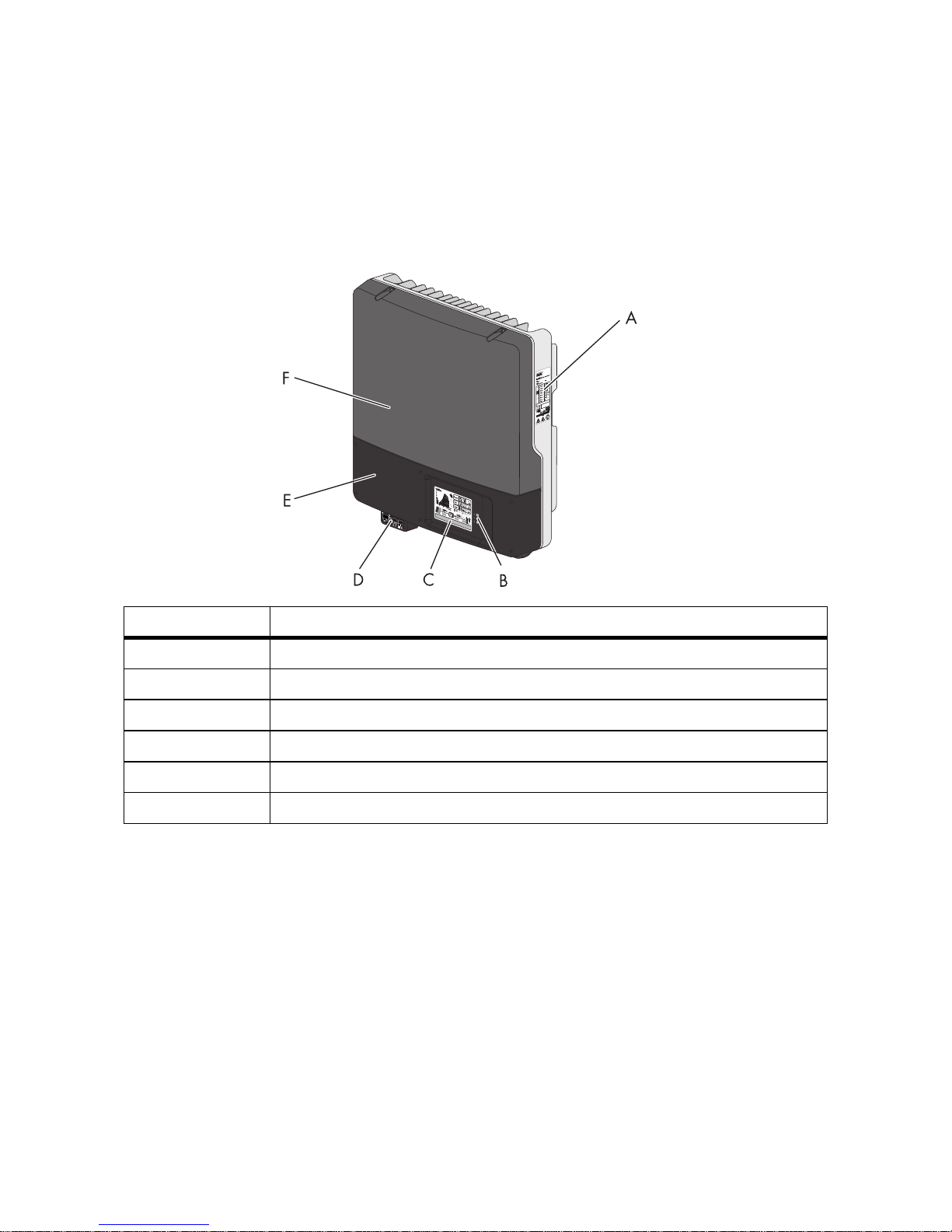
4 Product Description
4.1 Sunny Boy
The Sunny Boy is a PV inverter, which converts the direct current of the PV array to grid-compliant
alternating current and feeds it into the electricity grid.
*optional
Position Designation
A Type label
B LEDs
C Display
D Electronic Solar Switch*
E Lower enclosure lid
F Upper enclosure lid
Product Description SMA Solar Technology AG
16 SB25_30TLST_21-IA-IEN121110 Installation Manual
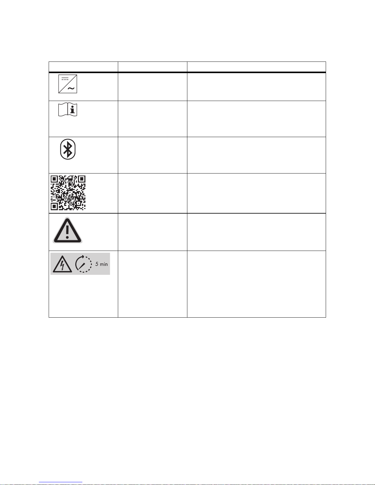
4.2 Symbols on the Inverter
* QR-Code is a registered trademark of DENSO WAVE INCORPORATED.
Symbol Designation Explanation
Inverter This symbol defines the function of the green LED.
The green LED indicates the operating state of the
inverter.
Read the
documentation!
This symbol defines the function of the red LED
which indicates a fault or disturbance. Read the
manual to remedy the fault or disturbance.
Bluetooth This symbol defines the function of the blue LED.
The blue LED indicates that communication via
Bluetooth is activated.
QR-Code
®
* for SMA
bonus programme
For information on the SMA bonus programme,
see www.SMA-Bonus.com.
NOTICE, danger! Observe the connection requirements for the
second protective conductor in Section
6.3.1"Conditions for the AC Connection"
(page32).
Danger to life due to
high voltages in the
inverter
The capacitors in the inverter may be charged
with very high voltages.
• Disconnect the inverter from voltage
sources (see Section 8.2) and wait
5 minutes before opening the upper lid, in
order to allow time for the capacitors to
discharge.
SMA Solar Technology AG Product Description
Installation Manual SB25_30TLST_21-IA-IEN121110 17
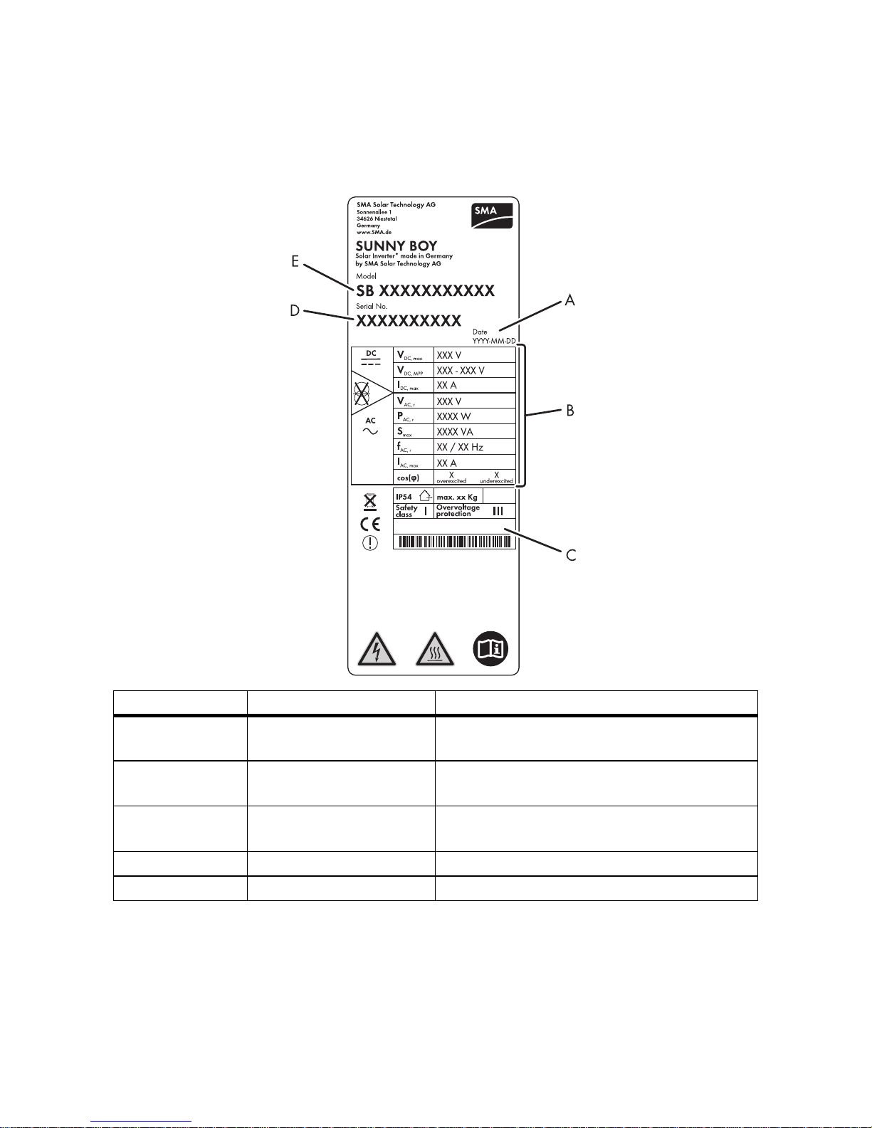
4.3 Type Label
The type label provides a unique identification of the inverter. The type label is on the right-hand side
of the enclosure.
The information on the type label is intended to help you use the inverter safely and receive better
customer support from the SMA Service Line. The type label must be permanently attached to the
inverter.
Position Designation Explanation
A Date Manufacturing date of the inverter
(year-month-day)
B Device-specific
characteristics
‒
C Additional information Field for additional information, e.g.
country-specific standard information
D Serial No. Inverter serial number
E Model Device type
Product Description SMA Solar Technology AG
18 SB25_30TLST_21-IA-IEN121110 Installation Manual
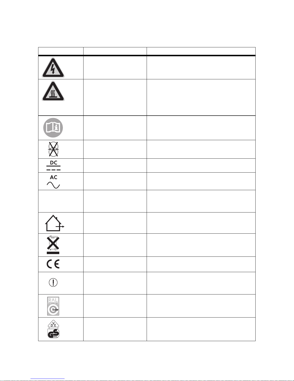
Symbols on the Type Label
Symbol Designation Explanation
Danger to life due to high
voltages.
The inverter operates at high voltages. All work
on the inverter must be carried out by skilled
workers only.
Risk of burns from hot
surfaces
The inverter can become hot during operation.
Avoid contact during operation. Allow the
inverter to cool down sufficiently before carrying
out any work. Wear personal protective
equipment such as safety gloves.
Read the documentation Observe all documentation that is supplied with
the inverter.
Without transformer The inverter is transformerless.
DC Direct current
AC Alternating current
Degree of protection IP54 The inverter is protected against dust deposits in
the interior and against splashes of water from all
angles.
Outdoor The inverter is suitable for outdoor installation.
Proper disposal The inverter must not be disposed of together with
the household waste.
CE marking The inverter complies with the requirements of the
applicable EC directives.
Device class label The product is equipped with a wireless
component that complies with the harmonised
standards.
RAL quality mark for solar
products
The inverter complies with the requirements of the
German Institute for Quality Assurance and
Labelling.
Certified safety The inverter complies with the requirements of the
European Equipment and Product Safety Act.
IP54
SMA Solar Technology AG Product Description
Installation Manual SB25_30TLST_21-IA-IEN121110 19
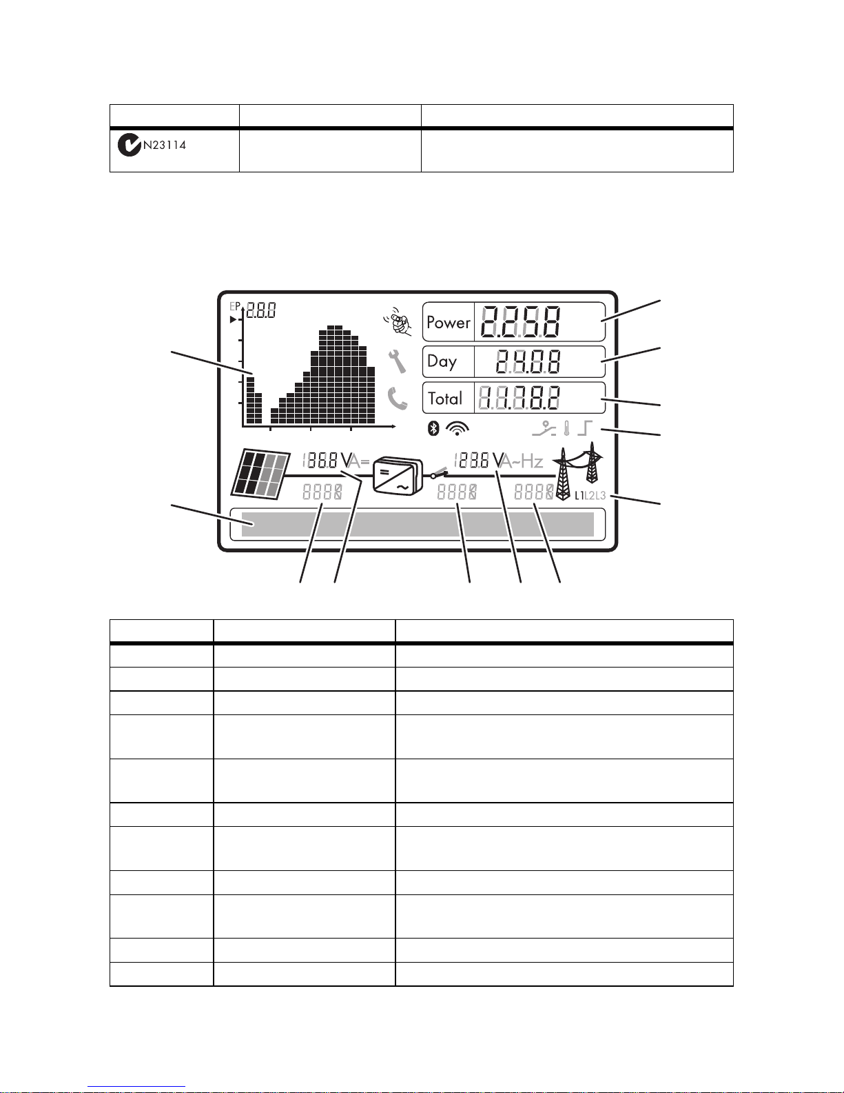
4.4 Display
The display shows the current operating data of the inverter (e.g. status, power, input voltage) as well
as faults and disturbances.
Australian mark of
conformity
The inverter complies with the requirements of the
applicable Australian guidelines.
Position Designation Explanation
A Power Displays the current power
B Day Displays the daily energy
C Total Displays the total amount of energy fed in until now
D Active functions The symbols indicate which communication or power
regulation functions are enabled.
E Line conductor assignment Shows assignment of the inverter to a line conductor.
It is also used for external power limitation.
F Electricity grid event number Event number of a disturbance in the electricity grid
G Output voltage/output
current
The display alternately shows the output voltage and
the output current of the inverter.
H Inverter event number Event number of a device disturbance
I Input voltage/input current The display alternately shows the input voltage and
the input current of the inverter.
K PV array event number Event number of a disturbance in the PV array
L Text line The text line shows event messages or instructions.
Symbol Designation Explanation
kVAr
kVArh
kWh
MVArh
MWh
kW
kWh
A
B
C
D
E
F
G
H
K
L
M
I
t/hday
Product Description SMA Solar Technology AG
20 SB25_30TLST_21-IA-IEN121110 Installation Manual
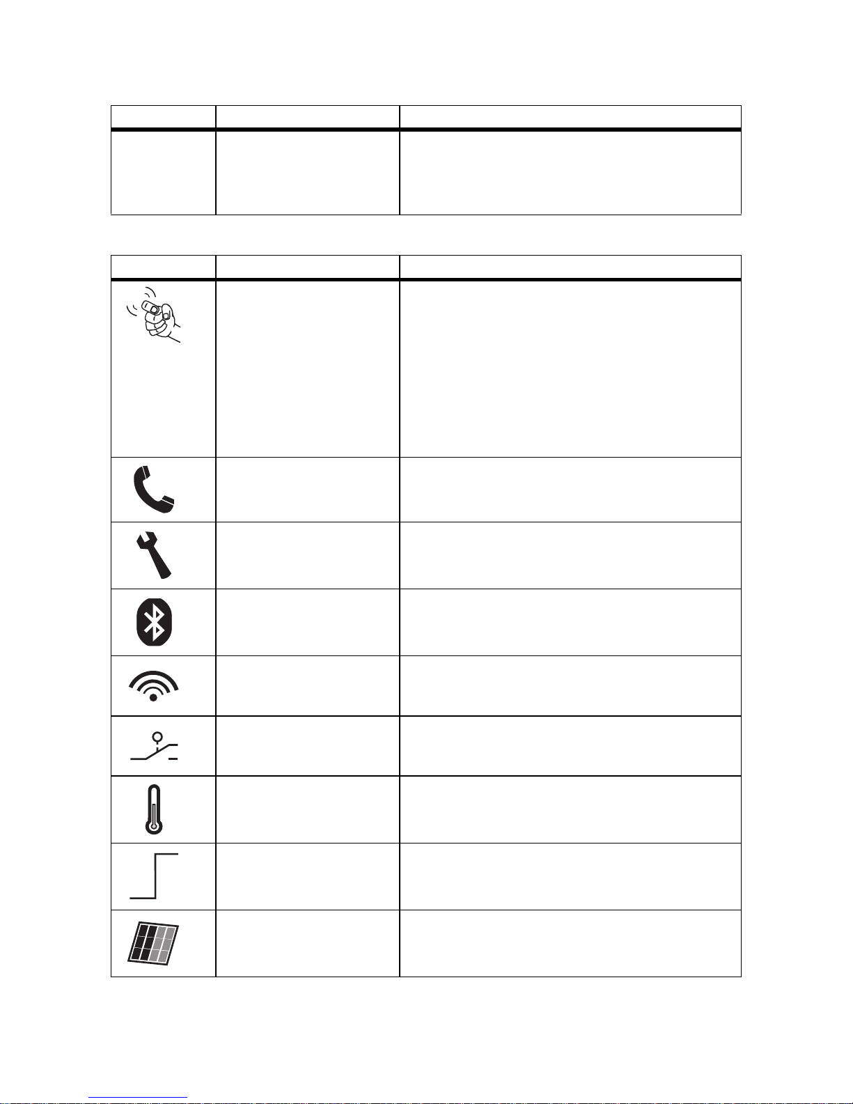
Symbols on the Display
M Power and yield curve The diagram shows the changes in power over the
last 16 feed-in hours or the energy yields over the last
16 days. Tap the display once to switch between
views.
Symbol Designation Explanation
Tap symbol You can operate the display by tapping it:
• Single tap: the backlight switches on or the
display scrolls one message further.
• Double tap: the display shows, in succession,
the firmware version, the serial number or
description of the inverter, the Bluetooth NetID,
the set country standard and the display
language.
Telephone receiver Device disturbance present. Contact the SMA Service
Line.
Spanner Signifies a disturbance that can be resolved on-site.
Bluetooth Bluetooth communication is enabled.
Bluetooth connection Bluetooth connection to other devices is active.
Multi-function relay The multi-function relay is active.
Temperature symbol The power of the inverter is limited due to excessive
temperature.
Power limitation The external active power limitation via the Power
Reducer Box is active.
PV array ‒
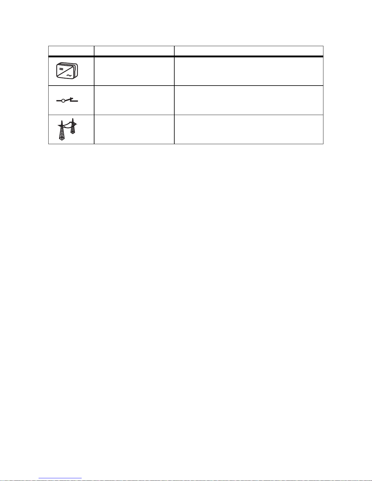
Position Designation Explanation
SMA Solar Technology AG Product Description
Installation Manual SB25_30TLST_21-IA-IEN121110 21
Inverter ‒
Grid relay If the grid relay is closed, the inverter feeds power into
the grid. If the grid relay is open, the inverter is
disconnected from the electricity grid.
Electricity grid ‒
Symbol Designation Explanation
Product Description SMA Solar Technology AG
22 SB25_30TLST_21-IA-IEN121110 Installation Manual
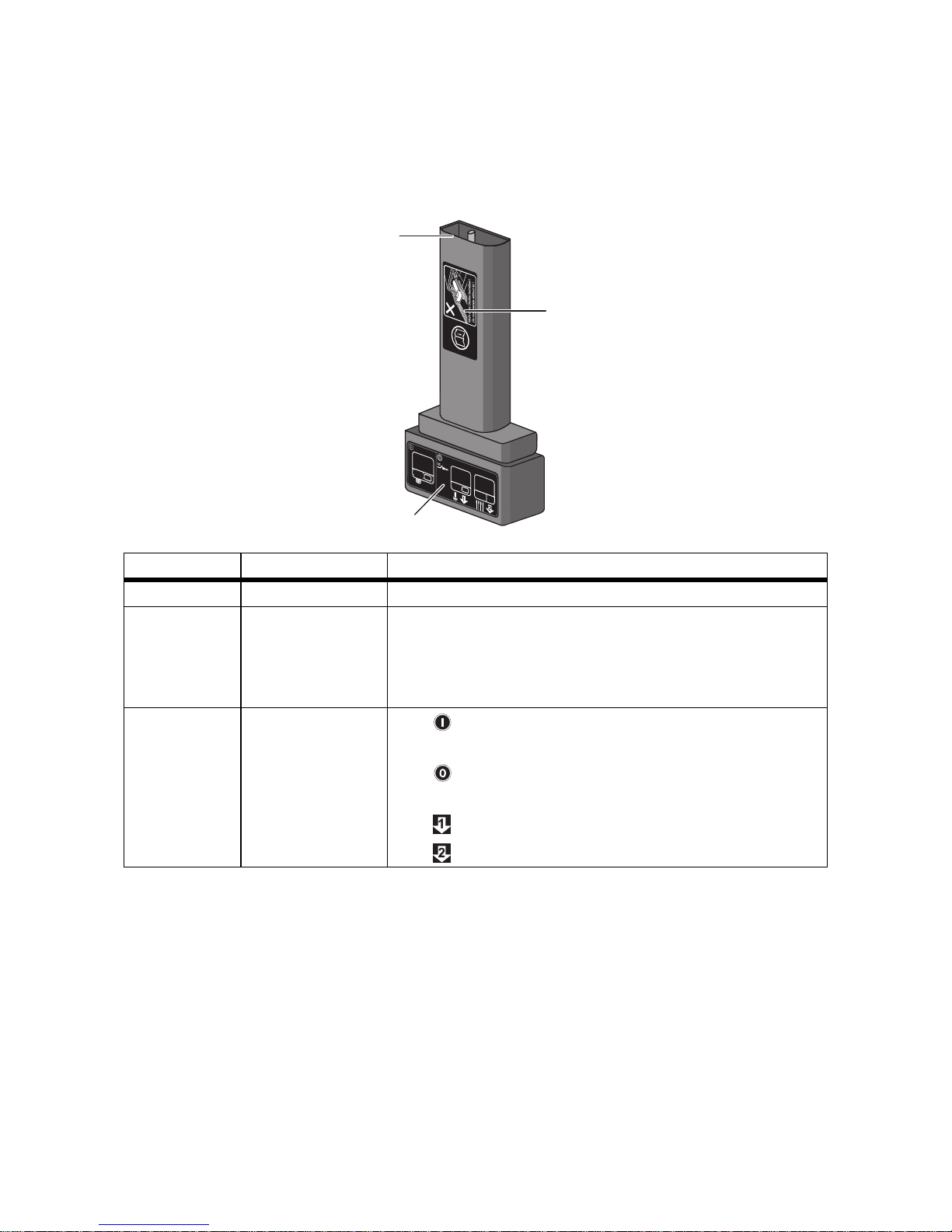
4.5 Electronic Solar Switch
The ESS is an optional DC load disconnect unit. The ESS prevents electric arcs from forming when you
remove the DC connector.
When plugged in, the ESS forms a conductive path between the PV array and the inverter. Removing
the ESS interrupts the electric circuit and allows you to safely disconnect the DC connectors from the
inverter.
Position Designation Explanation
A Plug ‒
B Safety precautions
sticker
• Never operate the inverter without the lower enclosure
lid in place.
• Observe all documentation that accompanies the
inverter.
C ESS sticker • If the ESS is plugged in, the DC circuit remains
closed.
• To interrupt the DC circuit, you must perform
steps 1 and 2.
• Remove the ESS.
• Remove all DC connectors.
B
A
C

SMA Solar Technology AG Product Description
Installation Manual SB25_30TLST_21-IA-IEN121110 23
4.6 Communication
The inverter is equipped with a Bluetooth interface as standard. A multi-function relay and an
additional communication interface (e.g. RS485) can be retrofitted. The inverter can communicate
with special SMA communication products (e.g. data logger, software) or other inverters via the
communication interfaces. You can only adjust the inverter's operating parameters using
SMA communication products.
If you order an inverter with an additional communication interface, the communication interface is
built in upon delivery.
If you communicate via Bluetooth, you can protect the inverter with a plant password for the user and
a plant password for the installer. All inverters are delivered with the same factory-installed
passwords. You must change plant passwords using a communication product in order to protect the
PV plant from unauthorised access.
If you do not communicate via Bluetooth, deactivate Bluetooth communication (see 6.6.2"Setting the
Bluetooth NetID" (page53)). This protects your PV plant from unauthorised access.
4.7 Multi-Function Relay
The inverter may be equipped with a multi-function relay. The multi-function relay is an interface for
error messages or for controlling loads. Disturbances can be transmitted to a disturbance sensor. For
this purpose, the multi-function relay switches the disturbance sensor on and off. The multi-function
relay can control a load via a contactor.
For this purpose, the inverter determines when the load is switched on and off, depending on the
operating parameters and measured values. You can configure the multi-function relay for various
operating modes (see Technical Description "Multi-functional relay and OptiTrac Global Peak"
available at www.SMA.de/en).
Various parameter displays
Depending on the type of communication, RS485 or Bluetooth, the parameters and
messages are displayed differently on the communication products.
Example: parameter display for the country standard
• For communication with RS485: "CntrySet" parameter
• For communication with Bluetooth: "Set country standard" parameter

Product Description SMA Solar Technology AG
24 SB25_30TLST_21-IA-IEN121110 Installation Manual
4.8 Grid Management
The inverter is equipped with grid management functions.
You can activate and configure the functions via operating parameters depending on the
requirements of the network operator (e.g. provision of reactive power, active power limitation).
For detailed information on the parameters of these functions, see the Technical Descriptions
"Measured Values, Operating Parameters and Event Messages" and "Parameter Settings ‒
SUNNY BOY 2500TL / 3000TL Single Tracker SUNNY BOY 3000TL / 3600TL / 4000TL /
5000TL" at www.SMA.de/en in the "Technical Description" category for the respective inverter.
4.9 Varistors
Varistors are voltage-dependent resistors that protect the inverter against overvoltage. The inverter is
equipped with 2 thermally monitored varistors.
The function of the varistors can diminish with age or repeated strain as a result of overvoltage. This
can cause varistor wear. The inverter detects if one of the varistors is defective and indicates a
disturbance.
The varistors are specially manufactured for use in the inverter and are not commercially available.
You must order new varistors directly from SMA Solar Technology AG.
SMA Solar Technology AG Mounting
Installation Manual SB25_30TLST_21-IA-IEN121110 25
5 Mounting
5.1 Safety
5.2 Selecting the Mounting Location
Consider the following requirements when selecting the mounting location:
• The mounting location must be inaccessible to children.
• The mounting method and location must be suitable for the inverter's weight and dimensions
(see Section 13"Technical Data" (page92)).
• Mount on a solid surface.
• The mounting location must be clear and safely accessible at all times without the use of
additional aids such as scaffolding or lifting platforms. Non-fulfillment of these criteria may
restrict the execution of service assignments.
DANGER!
Danger to life due to fire or explosions.
Despite careful construction, electrical devices can cause fires.
• Do not mount the inverter on flammable construction materials.
• Do not mount the inverter in areas where highly flammable materials are stored.
• Do not mount the inverter in a potentially explosive atmosphere.
CAUTION!
Risk of burns due to hot enclosure parts
• Mount the inverter in such a way that it cannot be touched inadvertently during
operation.
CAUTION!
Risk of injury due to the heavy weight of the inverter.
• For mounting, remember that the inverter weighs 23 kg.
Mounting SMA Solar Technology AG
26 SB25_30TLST_21-IA-IEN121110 Installation Manual
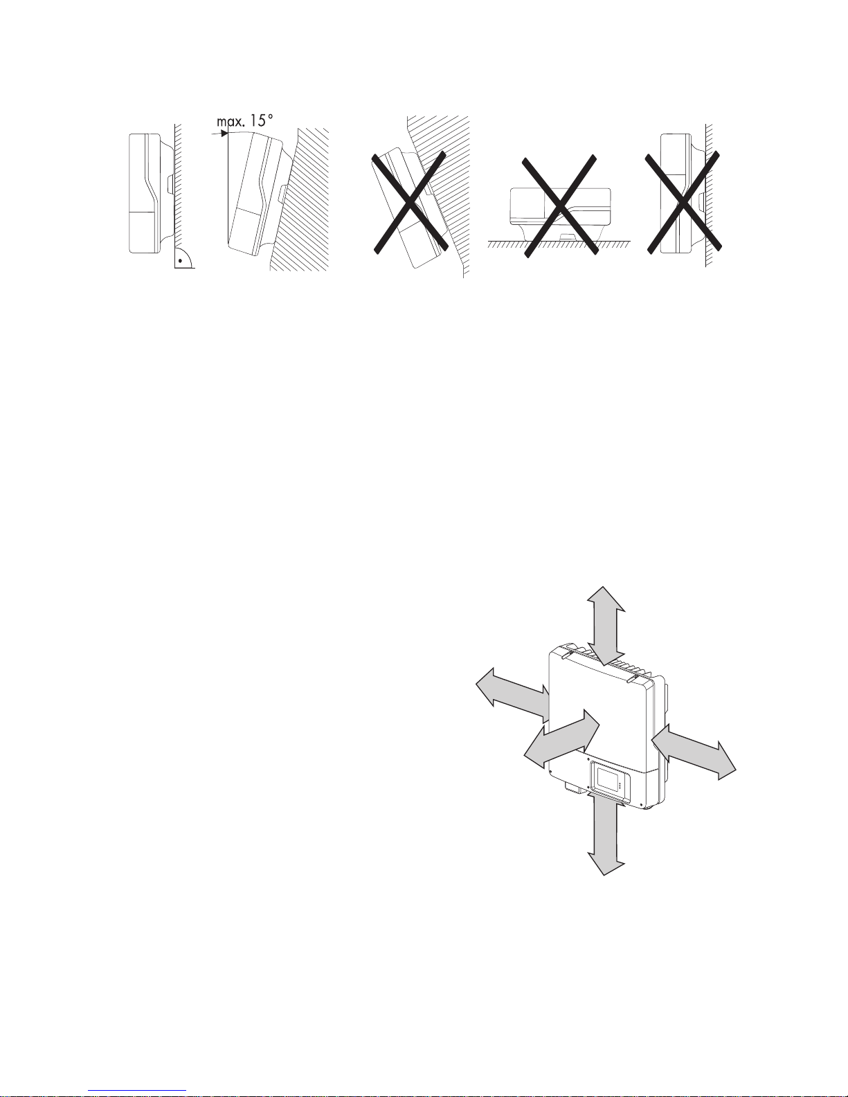
• Mount vertically or tilted backwards by max. 15°.
• The connection area must point downwards.
• Never mount the device with a forward tilt.
• Never mount the device with a sideways tilt.
• Do not mount horizontally.
• Mount at eye level so that operating states can be read at all times.
• The ambient temperature should be below 40°C to ensure optimum operation.
• Do not expose the inverter to direct solar irradiation as this can cause excessive heating and
thus power reduction.
• To avoid audible vibrations in living areas, do not mount the unit on plasterboard walls or
similar. When in use, the inverter emits noises which may be perceived as a nuisance in a living
area.
• Observe the recommended minimum clearances to
the walls as well as to other inverters and objects as
shown in the diagram. That ensures sufficient heat
dissipation and gives you enough space to unplug
the ESS.
• If multiple inverters are mounted in areas with high
ambient temperatures, increase the clearances
between the inverters and ensure an adequate
fresh-air supply. This prevents a reduction in inverter
power as a result of high temperatures (details on
temperature derating can be found in the Technical
Information "Temperature Derating" at
www.SMA.de/en). A fan is available as an
accessory for connection to the inverter (see
Section 14"Accessories" (page98)).
500 mm
100 mm
100 mm
50 mm
300 mm
SMA Solar Technology AG Mounting
Installation Manual SB25_30TLST_21-IA-IEN121110 27
5.3 Mounting the Inverter
Supplementary mounting material (not included in the scope of delivery):
– 3 screws (diameter: at least 6 mm)
– 3 wall plugs
– 3 washers (external diameter: at least 18 mm)
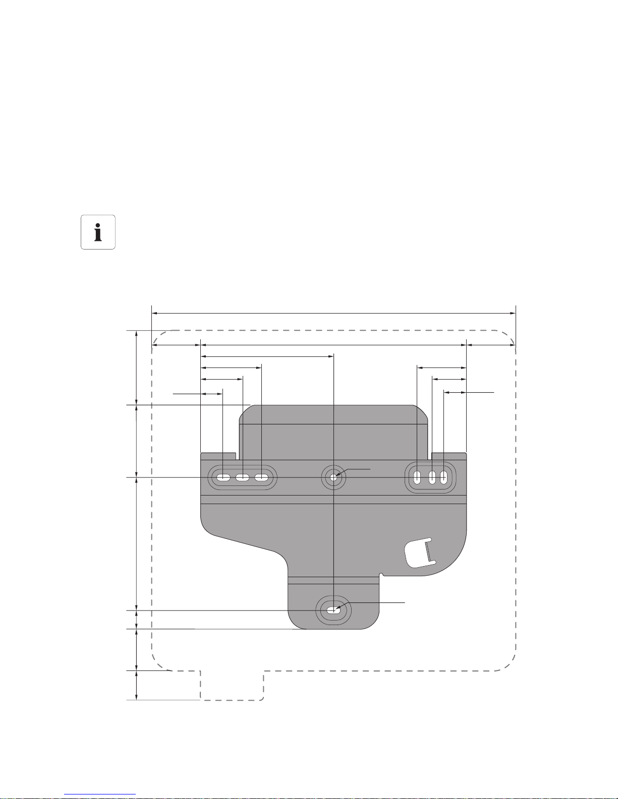
1. Use the wall mounting bracket as a drilling template and mark the positions of the drill holes.
Number of drill holes to use
• When mounting onto the wall, use at least 2 of the horizontal holes and the lower
centre hole.
• Use the two holes in the centre when mounting the device to a pillar.
490 mm
335 mm
175 mm
80 mm
55 mm
33 mm
175 mm
65 mm
45 mm
30 mm
9 mm
9 mm x 18 mm
70 mm
70 mm
31
mm
25
mm
57mm
98 mm
133 mm
Mounting SMA Solar Technology AG
28 SB25_30TLST_21-IA-IEN121110 Installation Manual
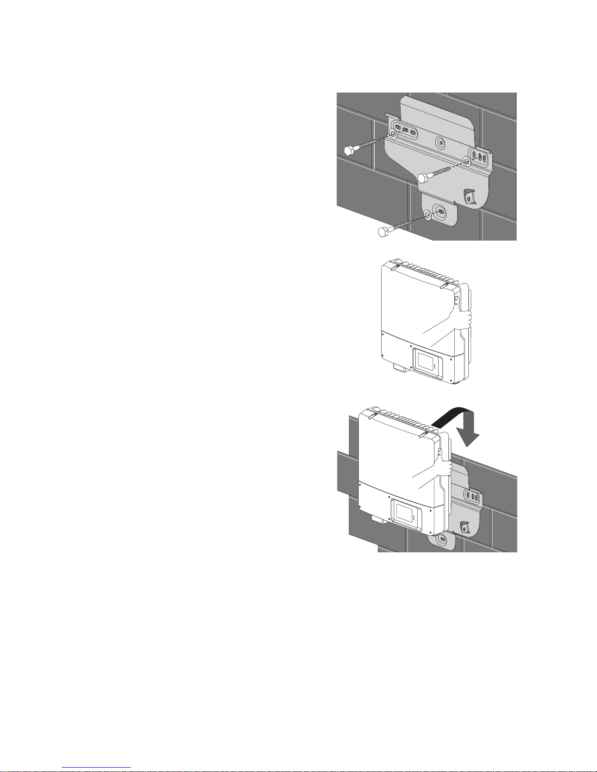
2. Drill the holes.
3. Attach the wall mounting bracket using appropriate
screws (diameter min. 6 mm) and washers (outer
diameter min. 18 mm).
4. Carry the inverter using the recessed grips on the
sides.
5. Hook the inverter into the wall mounting bracket
from above.
6. Check both sides of the inverter to make sure it is correctly in place.
SMA Solar Technology AG Mounting
Installation Manual SB25_30TLST_21-IA-IEN121110 29
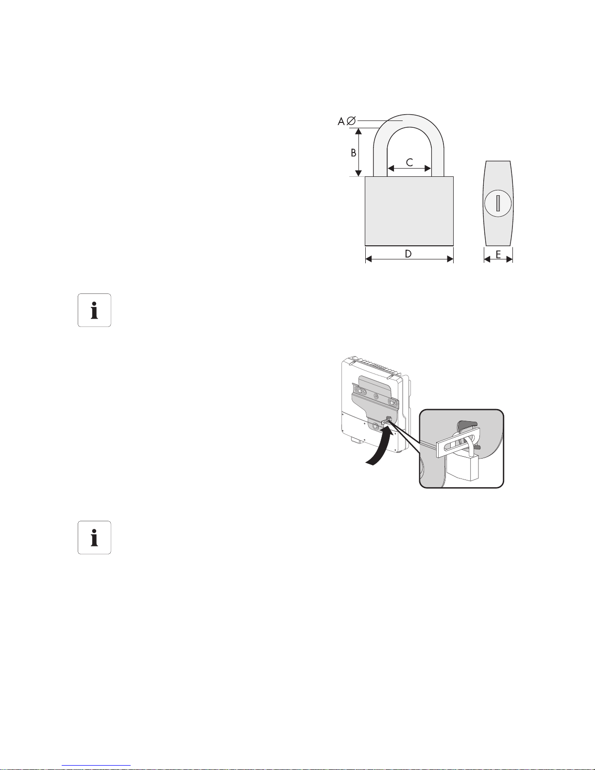
Optional Theft Protection
To protect the inverter from theft, you can lock it to the wall mounting bracket with a padlock.
The padlock must meet the following requirements:
–Size:
A: 6 mm … 8 mm diameter
B: 23 mm … 29 mm
C: 23 mm … 28 mm
D: 39 mm … 50 mm
E: 13 mm … 18 mm
–Stainless
– Hardened shackle
– Secured lock cylinder
• Route the lock shackle from the centre of the device
outwards through the metal clip on the wall
mounting bracket and the slot on the inverter and
close the lock.
Outdoor Mounting
Always use a lock suitable for outdoor mounting. Check the padlock on a regular basis to
ensure it is working properly.
Storage of the key
Keep the key in a safe place in case it is needed for service purposes.
Electrical Connection SMA Solar Technology AG
30 SB25_30TLST_21-IA-IEN121110 Installation Manual
6 Electrical Connection
6.1 Safety
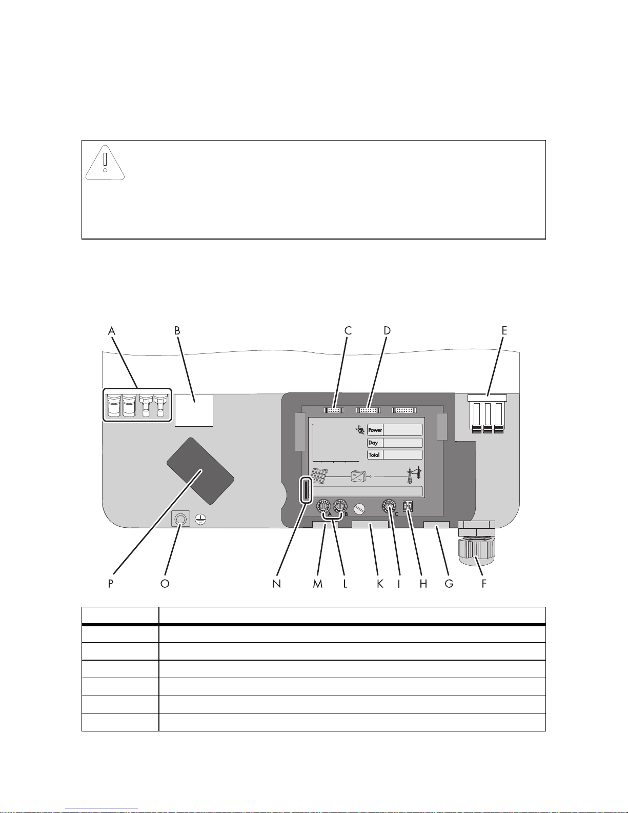
6.2 Overview of the Connection Area
The following figure shows the inverter's connection area with the lower enclosure lid open.
NOTICE!
Electrostatic discharge can damage the inverter
Internal components of the inverter can be irreparably damaged by electrostatic
discharge.
• Earth yourself before touching any components.
Position Description
A DC connectors for connecting the strings
B Jack for connecting the ESS*
C Plug for connecting the optional multi-function relay or additional fan kit
D Plug for optional communication via RS485
E Terminal for the AC cable
F Cable gland (12 mm … 21 mm) for routing the AC cable
 Loading...