

SMA SUNNY BOY 1.5, SUNNY BOY 2.0, SUNNY BOY 2.5 Operating Manual
SUNNY TRIPO
WER
SUNNY BOY
SMA
SBxx-1VL-40-BE-en-13 | Version 1.3ENGLISH
Operating manual
SUNNY BOY 1.5 / 2.0 / 2.5

Legal Provisions
SMA Solar Technology AG
Operating manualSBxx-1VL-40-BE-en-132
Legal Provisions
The information contained in these documents is the property of SMA Solar Technology AG. No
part of this document may be reproduced, stored in a retrieval system, or transmitted, in any form or
by any means, be it electronic, mechanical, photographic, magnetic or otherwise, without the prior
written permission of SMA Solar Technology AG. Internal reproduction used solely for the purpose
of product evaluation or other proper use is allowed and does not require prior approval.
SMA Solar Technology AG makes no representations or warranties, express or implied, with
respect to this documentation or any of the equipment and/or software it may describe, including
(with no limitation) any implied warranties of utility, merchantability, or fitness for any particular
purpose. All such representations or warranties are expressly disclaimed. Neither SMA Solar
Technology AG nor its distributors or dealers shall be liable for any indirect, incidental, or
consequential damages under any circumstances.
The exclusion of implied warranties may not apply in all cases under some statutes, and thus the
above exclusion may not apply.
Specifications are subject to change without notice. Every attempt has been made to make this
document complete, accurate and up-to-date. Readers are cautioned, however, that product
improvements and field usage experience may cause SMA Solar Technology AG to make changes
to these specifications without advance notice, or per contract provisions in those cases where a
supply agreement requires advance notice. SMA Solar Technology AG shall not be responsible for
any damages, including indirect, incidental or consequential damages, caused by reliance on the
material presented, including, but not limited to, omissions, typographical errors, arithmetical errors
or listing errors in the content material.
SMA Warranty
You can download the current warranty conditions from the Internet at www.SMA-Solar.com.
Software licenses
The licenses for the used software modules can be called up on the user interface of the product.
Trademarks
All trademarks are recognized, even if not explicitly identified as such. Missing designations do not
mean that a product or brand is not a registered trademark.
SMA Solar Technology AG
Sonnenallee 1
34266 Niestetal
Germany
Tel. +49 561 9522-0
Fax +49 561 9522-100
www.SMA.de
Email: info@SMA.de
Status: 1/17/2019
Copyright © 2018 SMA Solar Technology AG. All rights reserved.

Table of Contents
SMA Solar Technology AG
Operating manual SBxx-1VL-40-BE-en-13 3
Table of Contents
1 Information on this Document................................................. 6
1.1 Validity........................................................................................................................ 6
1.2 Target Group.............................................................................................................. 6
1.3 Content and Structure of this Document ................................................................... 6
1.4 Levels of warning messages...................................................................................... 6
1.5 Symbols in the Document .......................................................................................... 7
1.6 Typographies in the document.................................................................................. 7
1.7 Designation in the document..................................................................................... 7
1.8 Additional Information............................................................................................... 7
2 Safety ........................................................................................ 9
2.1 Intended Use .............................................................................................................. 9
2.2 IMPORTANT SAFETY INSTRUCTIONS.................................................................... 9
3 Scope of Delivery ..................................................................... 13
4 Product Overview .................................................................... 14
4.1 Product Description.................................................................................................... 14
4.2 Symbols on the Product ............................................................................................. 15
4.3 Interfaces and Functions ............................................................................................ 16
4.4 LED Signals................................................................................................................. 18
5 Mounting................................................................................... 20
5.1 Requirements for Mounting ....................................................................................... 20
5.2 Mounting the Inverter................................................................................................. 22
6 Electrical Connection ................................................................ 24
6.1 Overview of the Connection Area............................................................................ 24
6.2 AC Connection........................................................................................................... 25
6.2.1 Requirements for the AC Connection.................................................... 25
6.2.2 Connecting the Inverter to the Utility Grid ............................................ 26
6.2.3 Connecting Additional Grounding........................................................ 28
6.3 Connecting the Network Cables............................................................................... 29
6.4 DC Connection........................................................................................................... 31
6.4.1 Requirements for the DC Connection.................................................... 31
6.4.2 Assembling the DC Connectors............................................................. 32
6.4.3 Connecting the PV Array........................................................................ 34
6.4.4 Disassembling the DC Connectors ........................................................ 35
7 Commissioning ......................................................................... 37

Table of Contents
SMA Solar Technology AG
Operating manualSBxx-1VL-40-BE-en-134
7.1 Commissioning Procedure ......................................................................................... 37
7.2 Commissioning the Inverter........................................................................................ 37
7.3 Selecting a configuration option............................................................................... 39
7.4 Starting the Self-Test (for Italy and Dubai)................................................................ 41
8 Operation ................................................................................. 43
8.1 Establishing a connection to the user interface ........................................................ 43
8.1.1 Establishing a Direct Connection via Ethernet ...................................... 43
8.1.2 Establishing a direct connection via WLAN ......................................... 43
8.1.3 Establishing a Connection via Ethernet in the local network ............... 45
8.1.4 Establishing a Connection via WLAN in the Local Network ............... 46
8.2 Logging In and Out of the User Interface................................................................. 47
8.3 Start Page Design of the User Interface.................................................................... 48
8.4 Starting the Installation Assistant............................................................................... 50
8.5 Activate WPS Function............................................................................................... 51
8.6 Switching WLAN On and Off................................................................................... 52
8.7 Switching the Dynamic Power Display Off............................................................... 53
8.8 Changing the Password............................................................................................. 53
8.9 Changing Operating Parameters.............................................................................. 54
8.10 Configuring the Country Data Set............................................................................. 55
8.11 Configuring Feed-In Management............................................................................ 55
8.12 Configuring the Modbus Function............................................................................. 56
8.13 Activating the Receipt of Control Signals (Only for Italy)........................................ 56
8.14 Deactivating Grounding Conductor Monitoring...................................................... 57
8.15 Configuring the Energy Meter................................................................................... 57
8.16 Setting SMA OptiTrac Global Peak ......................................................................... 58
8.17 Saving the Configuration in a File............................................................................. 58
8.18 Adopting a Configuration from a File....................................................................... 58
8.19 Updating the Firmware.............................................................................................. 59
9 Disconnecting the Inverter from Voltage Sources ................. 60
10 Cleaning the Inverter ............................................................... 62
11 Troubleshooting........................................................................ 63
11.1 Forgotten Password.................................................................................................... 63
11.2 Event Messages ......................................................................................................... 63
11.3 Checking the PV System for Ground Faults.............................................................. 77
12 Decommissioning the Inverter................................................. 82
13 Technical Data .......................................................................... 83

Table of Contents
SMA Solar Technology AG
Operating manual SBxx-1VL-40-BE-en-13 5
14 Contact ...................................................................................... 88
15 EU Declaration of Conformity ................................................. 90
1 Information on this Document
SMA Solar Technology AG
Operating manualSBxx-1VL-40-BE-en-136
1 Information on this Document
1.1 Validity
• SB1.5-1VL-40 (SunnyBoy 1.5) from firmware version 2.05.02.R
• SB2.0-1VL-40 (Sunny Boy 2.0) from firmware version 2.05.02.R
• SB2.0-1VL-40 (SunnyBoy 2.5) from firmware version 2.05.02.R
1.2 Target Group
This document is intended for qualified persons and end users. Only qualified persons are allowed
to perform the activities marked in this document with a warning symbol and the caption
"Qualifiedperson". Tasks that do not require any particular qualification are not marked and can
also be performed by end users. Qualified persons must have the following skills:
• Knowledge of how an inverter works and is operated
• Training in how to deal with the dangers and risks associated with installing, repairing and
using electrical devices and installations
• Training in the installation and commissioning of electrical devices and installations
• Knowledge of all applicable laws, standards and directives
• Knowledge of and compliance with this document and all safety information
1.3 Content and Structure of this Document
This document describes the mounting, installation, commissioning, configuration, operation,
troubleshooting and decommissioning of the product as well as the operation of the product user
interface.
You will find the latest version of this document and further information on the product in PDF format
and as eManual at www.SMA-Solar.com. You can also call up the eManual via the user interface
of the product.
Illustrations in this document are reduced to the essential information and may deviate from the real
product.
1.4 Levels of warning messages
The following levels of warning messages may occur when handling the product.
DANGER
Indicates a hazardous situation which, if not avoided, will result in death or serious injury.
WARNING
Indicates a hazardous situation which, if not avoided, could result in death or serious injury.
CAUTION
Indicates a hazardous situation which, if not avoided, could result in minor or moderate injury.
1 Information on this Document
SMA Solar Technology AG
Operating manual SBxx-1VL-40-BE-en-13 7
NOTICE
Indicates a situation which, if not avoided, can result in property damage.
1.5 Symbols in the Document
Symbol Explanation
Information that is important for a specific topic or goal, but is not safety-relevant
☐
Indicates a requirement for meeting a specific goal
☑
Desired result
✖
A problem that might occur
Example
Sections describing activities to be performed by qualified persons only
1.6 Typographies in the document
Typography Use Example
bold
• Messages
• Terminals
• Elements on a user interface
• Elements to be selected
• Elements to be entered
• Connect the insulated
conductors to the terminals
X703:1 to X703:6.
• Enter 10 in the field
Minutes.
>
• Connects several elements to be
selected
• Select Settings > Date.
[Button]
[Key]
• Button or key to be selected or
pressed
• Select [Enter].
1.7 Designation in the document
Complete designation Designation in this document
SunnyBoy Inverter, product
1.8 Additional Information
For more information, please go to www.SMA-Solar.com.
Title and information content Type of information
"Application for SMAGridGuard Code" Form
1 Information on this Document
SMA Solar Technology AG
Operating manualSBxx-1VL-40-BE-en-138
Title and information content Type of information
"PUBLIC CYBER SECURITY - Guidelines for a Secure PV System
Communication"
Technical information
"Efficiency and Derating"
Efficiency and derating behavior of the SMA inverters
Technical Information
"Parameters and Measured Values"
Overview of all inverter operating parameters and their configura-
tion options
Technical Information
"Modbus® parameters and measured values"
Device-specific register HTML file
Technical Information
"SMAModbus® Interface"
Information on the commissioning and configuration of the SMA
Modbus interface
Technical Information

2 Safety
SMA Solar Technology AG
Operating manual SBxx-1VL-40-BE-en-13 9
2 Safety
2.1 Intended Use
The Sunny Boy is a transformerless PV inverter which converts the direct current of the PV array to
grid-compliant alternating current and feeds it into the utility grid.
The product is suitable for indoor and outdoor use.
The product must only be operated with PV modules of protection class II in accordance with
IEC61730, application class A. The PV modules must be compatible with this product.
The product is not equipped with a transformer and therefore has no galvanic isolation. The
product must not be operated with PV modules whose outputs are grounded. This can cause the
product to be destroyed. The product may be operated with PV modules whose frame is grounded.
PV modules with a high capacity to ground must only be used if their coupling capacity does not
exceed 900nF (for information on how to calculate the coupling capacity, see the Technical
Information "Leading Leakage Currents" at www.SMA-Solar.com).
All components must remain within their permitted operating ranges and their installation
requirements at all times.
The product must only be used in countries for which it is approved or released by SMA Solar
Technology AG and the grid operator.
Use this product only in accordance with the information provided in the enclosed documentation
and with the locally applicable laws, regulations, standards and directives. Any other application
may cause personal injury or property damage.
Alterations to the product, e.g. changes or modifications, are only permitted with the express written
permission of SMA Solar Technology AG. Unauthorized alterations will void guarantee and
warranty claims and in most cases terminate the operating license. SMA Solar Technology AG
shall not be held liable for any damage caused by such changes.
Any use of the product other than that described in the Intended Use section does not qualify as the
intended use.
The enclosed documentation is an integral part of this product. Keep the documentation in a
convenient, dry place for future reference and observe all instructions contained therein.
This document does not replace and is not intended to replace any local, state, provincial, federal
or national laws, regulations or codes applicable to the installation, electrical safety and use of the
product. SMA Solar Technology AG assumes no responsibility for the compliance or noncompliance with such laws or codes in connection with the installation of the product.
The type label must remain permanently attached to the product.
2.2 IMPORTANT SAFETY INSTRUCTIONS
SAVE THESE INSTRUCTIONS
This section contains safety information that must be observed at all times when working on or with
the product.
2 Safety
SMA Solar Technology AG
Operating manualSBxx-1VL-40-BE-en-1310
The product has been designed and tested in accordance with international safety requirements. As
with all electrical or electronical devices, there are residual risks despite careful construction. To
prevent personal injury and property damage and to ensure long-term operation of the product,
read this section carefully and observe all safety information at all times.
DANGER
Danger to life due to electric shock when live components or DC cables are
touched
When exposed to sunlight, the PV modules generate high DC voltage which is present in the DC
cables. Touching live DC cables results in death or lethal injuries due to electric shock.
• Disconnect the product from voltage sources and make sure it cannot be reconnected
before working on the device.
• Do not touch non-insulated parts or cables.
• Do not disconnect the DC connectors under load.
• Wear suitable personal protective equipment for all work on the product.
DANGER
Danger to life due to electric shock when live components are touched on
opening the product
High voltages are present in the live parts and cables inside the product during operation.
Touching live parts and cables results in death or lethal injuries due to electric shock.
• Do not open the product.
DANGER
Danger to life due to electric shock from touching an ungrounded PV module
or array frame
Touching ungrounded PV modules or array frames results in death or lethal injuries due to electric
shock.
• Connect and ground the frame of the PV modules, the array frame and the electrically
conductive surfaces so that there is continuous conduction. Observe the applicable local
regulations.
2 Safety
SMA Solar Technology AG
Operating manual SBxx-1VL-40-BE-en-13 11
DANGER
Danger to life due to electric shock when touching live system components in
case of a ground fault
If a ground fault occurs, parts of the system may still be live. Touching live parts and cables
results in death or lethal injuries due to electric shock.
• Disconnect the product from voltage sources and make sure it cannot be reconnected
before working on the device.
• Touch the cables of the PV array on the insulation only.
• Do not touch any parts of the substructure or frame of the PV array.
• Do not connect PV strings with ground faults to the inverter.
DANGER
Danger to life due to electric shock in case of overvoltages and if surge
protection is missing
Overvoltages (e.g. in the event of a flash of lightning) can be further conducted into the building
and to other connected devices in the same network via the network cables or other data cables
if there is no surge protection. Touching live parts and cables results in death or lethal injuries due
to electric shock.
• Ensure that all devices in the same network are integrated in the existing overvoltage
protection.
• When laying the network cable outdoors, ensure that there is suitable surge protection at
the network cable transition from the product outdoors to the network inside the building.
• The Ethernet interface of the inverter is classified as "TNV-1" and offers protection against
overvoltages of up to 1.5kV.
CAUTION
Risk of burns due to hot enclosure parts
Some parts of the enclosure can get hot during operation.
• During operation, do not touch any parts other than the enclosure lid of the inverter.
CAUTION
Risk of injury due to weight of product
Injuries may result if the product is lifted incorrectly or dropped while being transported or when
attaching it to or removing it from the wall mounting bracket.
• Transport and lift the product carefully. Take the weight of the product into account.
• Wear suitable personal protective equipment for all work on the product.
2 Safety
SMA Solar Technology AG
Operating manualSBxx-1VL-40-BE-en-1312
NOTICE
Damage due to cleaning agents
The use of cleaning agents may cause damage to the product and its components.
• Clean the product and all its components only with a cloth moistened with clear water.
NOTICE
Destruction of the measuring device due to overvoltage
• Only use measuring devices with a DC input voltage range of 1000V or higher.

3 Scope of Delivery
SMA Solar Technology AG
Operating manual SBxx-1VL-40-BE-en-13 13
3 Scope of Delivery
Check the scope of delivery for completeness and any externally visible damage. Contact your
distributor if the scope of delivery is incomplete or damaged.
_
B
+
C
A
H
L
N
I
J
F
G
D E
Figure 1: Components included in the scope of delivery
Position Quantity Designation
A 1 Inverter
B 1 Negative DC connector
C 1 Positive DC connector
D 1 Clamping bracket
E 1 Cylindrical screw M5x16
F 1 Spring lock washer
G 1 Washer
H 1 AC connector
I 1 Connection cap
J 1 Quick reference guide with password label on the rear
side
The label contains the following information:
• PIC (Product Identification Code) identification key
for registering the system in SunnyPortal
• RID (Registration Identifier) registration ID for
registering the system in SunnyPortal
• WLAN password WPA2-PSK (WiFi Protected Access
2 - Preshared Key) for direct connection to the
inverter via WLAN
4 Product Overview
SMA Solar Technology AG
Operating manualSBxx-1VL-40-BE-en-1314
4 Product Overview
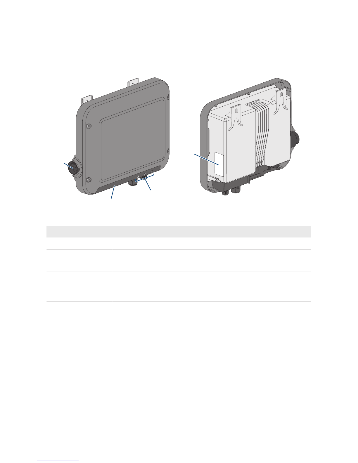
4.1 Product Description
B
A
C
D
Figure 2: Design of the SunnyBoy
Position Designation
A DC load-break switch
B LEDs
The LEDs indicate the operating state of the inverter.
C Connection cap
Connection area with cable glands for connection to the utility grid and
the local network
D Type label
The type label clearly identifies the product. The type label must remain
permanently attached to the product. You will find the following information on the type label:
• Device type (Model)
• Serial number (Serial No. or S/N)
• Date of manufacture
• Identification key (PIC) for registration in Sunny Portal
• Registration ID (RID) for registration in Sunny Portal
• WLAN password (WPA2-PSK) for the direct connection to the user
interface of the inverter via WLAN
• Device-specific characteristics
4 Product Overview
SMA Solar Technology AG
Operating manual SBxx-1VL-40-BE-en-13 15
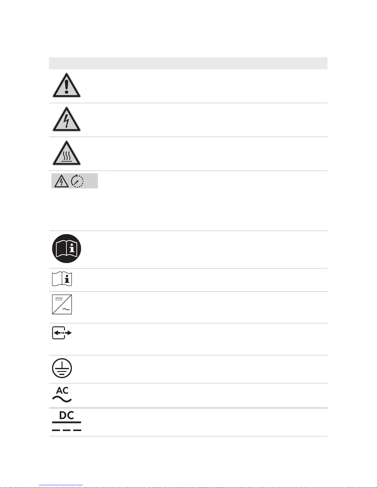
4.2 Symbols on the Product
Symbol Explanation
Beware of a danger zone
This symbol indicates that the product must be additionally grounded if addi-
tional grounding or equipotential bonding is required at the installation site.
Beware of electrical voltage
The product operates at high voltages.
Beware of hot surface
The product can get hot during operation.
5 min
Danger to life due to high voltages in the inverter; observe a waiting time of 5
minutes
High voltages that can cause lethal electric shocks are present in the live components of the inverter.
Prior to performing any work on the inverter, disconnect it from all voltage
sources as described in this document.
Observe the documentation
Observe all documentation supplied with the product.
Observe the documentation
Together with the red LED, this symbol indicates an error.
Inverter
Together with the green LED, this symbol indicates the operating state of the in-
verter.
Data transmission
Together with the blue LED, this symbol indicates the status of the network connection.
Grounding conductor
This symbol indicates the position for connecting a grounding conductor.
Alternating current
Direct current
4 Product Overview
SMA Solar Technology AG
Operating manualSBxx-1VL-40-BE-en-1316
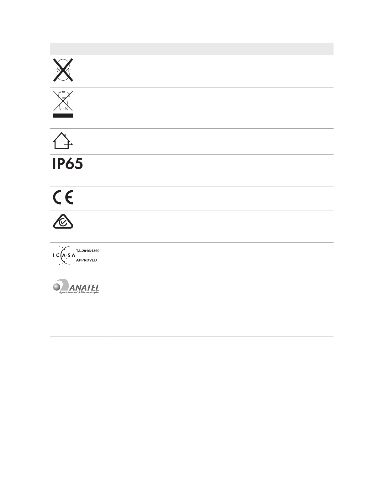
Symbol Explanation
The product is has no galvanic isolation.
WEEE designation
Do not dispose of the product together with the household waste but in accor-
dance with the disposal regulations for electronic waste applicable at the installation site.
The product is suitable for outdoor installation.
Degree of protectionIP65
The product is protected against the penetration of dust and water that is di-
rected as a jet against the enclosure from all directions.
CE marking
The product complies with the requirements of the applicable EU directives.
RCM (Regulatory Compliance Mark)
The product complies with the requirements of the applicable Australian standards.
ICASA
The product complies with the requirements of the South African standards for
telecommunication.
03931-16-03337
ANATEL
The product complies with the requirements of the Brazilian standards for
telecommunication.
Este equipamento opera em caráter secundário, isto é, não tem direito a pro-
teção contra interferência prejudicial, mesmo de estações do mesmo tipo, e
não pode causar interferência a sistemas operando em caráter primário.
4.3 Interfaces and Functions
The inverter is equipped with the following interfaces and functions:
User interface for monitoring and configuration
The product is equipped as standard with an integrated webserver, which provides a user interface
for configuring and monitoring the product. The product user interface can be called up via the web
browser if there is an existing connection to an end device (e.g. computer, tablet PC or
smartphone).

4 Product Overview
SMA Solar Technology AG
Operating manual SBxx-1VL-40-BE-en-13 17
SMA Speedwire
The product is equipped with SMASpeedwire as standard. SMASpeedwire is a type of
communication based on the Ethernet standard. SMASpeedwire is designed for a data transfer
rate of 100Mbps and enables optimum communication between Speedwire devices within
systems.
SMA Webconnect
The inverter is equipped with a Webconnect function as standard. The Webconnect function
enables direct data transmission between the inverters and Internet portals SunnyPortal and
SunnyPlaces without any additional communication device and for a maximum of 4 inverters per
visualized system. In PV systems with more than 4 inverters, there is the option of establishing data
transmission between the inverters and SunnyPortal via the data logger (e.g.,
SMADataManager) or distributing the inverters over several systems. If there is an existing WLAN
or Ethernet connection, you can directly access your visualized system via the web browser on your
end device.
Webconnect enables - for PV systems operated in Italy - the connection or disconnection of the
inverter to or from the utility grid and the specifying of the frequency limits to be used via
IEC61850-GOOSE messages.
WLAN
The product is equipped with a WLAN interface as standard. The inverter is delivered with the
WLAN interface activated as standard. If you do not want to use WLAN, you can deactivate the
WLAN interface.
In addition, the inverter has a WPS (WiFi Protected Setup) function. The WPS function connects the
inverter automatically with an end device (e.g. smartphone, tablet PC or computer). You can
activate the WPS function by tapping on the enclosure lid twice in quick succession. The open
interface will then be signalized via the rapid flashing of the blue LED on the inverter.
Limited function in the event of frost
The integrated WLAN interface is only designed for temperatures down to -20°C.
• Deactivate the WLAN interface at low temperatures (see Section8.6, page52).
Grid management services
The product is equipped with service functions for grid management.
Depending on the requirements of the grid operator, you can activate and configure the functions
(e.g. active power limitation) via operating parameters.
SMAOptiTracGlobalPeak
SMAOptiTracGlobalPeak is an advancement of SMAOptiTrac and allows the operating point of
the inverter to follow the optimal operating point of the PV array (MPP) precisely at all times. In
addition, with the aid of SMAOptiTracGlobalPeak, the inverter detects several maximum power
points in the available operating range, such as may occur particularly with partially shaded
strings. SMA OptiTrac Global Peak is enabled by default.
4 Product Overview
SMA Solar Technology AG
Operating manualSBxx-1VL-40-BE-en-1318
All-pole sensitive residual-current monitoring unit
The all-pole sensitive residual-current monitoring unit detects alternating and direct differential
currents. In single-phase and three-phase inverters, the integrated differential current sensor detects
the current difference between the neutral conductor and the line conductor(s). If the current
difference increases suddenly, the inverter disconnects from the utility grid.
Connection of the SMAEnergyMeter
If an SMAEnergyMeter is installed in the PV system, the inverter can receive data on the
household energy consumption directly from this.
SMA Smart Connected
SMA Smart Connected is the free monitoring of the inverter via the SMA SunnyPortal. Thanks to
SMA Smart Connected, the PV system operator and qualified person will be informed automatically
and proactively about inverter events that occur.
SMA Smart Connected is activated during registration in SunnyPortal. In order to use SMA Smart
Connected, it is necessary that the inverter is permanently connected to SunnyPortal and the data
of the PV system operator and qualified person is stored in SunnyPortal and up-to-date.
4.4 LED Signals
LED signal Explanation
The green LED is flashing
(twoseconds on and
twoseconds off)
Waiting for feed-in conditions
The conditions for feed-in operation are not yet met. As soon as the
conditions are met, the inverter will start feed-in operation.
The green LED flashes
quickly
Update of central processing unit
The central processing unit of the inverter is being updated.
The green LED is glowing Feed-in operation
The inverter feeds in with a power of at least 90%.
The green LED is pulsing Feed-in operation
The inverter is equipped with a dynamic power display via the green
LED. Depending on the power, the green LED pulses fast or slow. If
necessary, you can switch off the dynamic power display via the
green LED.
The green LED is off The inverter is not feeding into the utility grid.
The red LED is glowing Event occurred
If an event occurs, a distinct event message and the corresponding
event number will be displayed in addition on the inverter user interface or in the communication product.
The blue LED flashes slowly
for approx. one minute
Communication connection is being established
The inverter is establishing a connection to a local network or is es-
tablishing a direct connection to an end device via Ethernet (e.g.
computer, tablet PC or smartphone).

4 Product Overview
SMA Solar Technology AG
Operating manual SBxx-1VL-40-BE-en-13 19
LED signal Explanation
The blue LED flashes quickly
for approx. two minutes.
WPS active
The WPS function is active.
The blue LED is glowing Communication active
There is an active connection with a local network or there is a direct connection with an end device via Ethernet (e.g. computer,
tablet PC or smartphone).
5 Mounting
SMA Solar Technology AG
Operating manualSBxx-1VL-40-BE-en-1320
5 Mounting
5.1 Requirements for Mounting
Requirements for the Mounting Location:
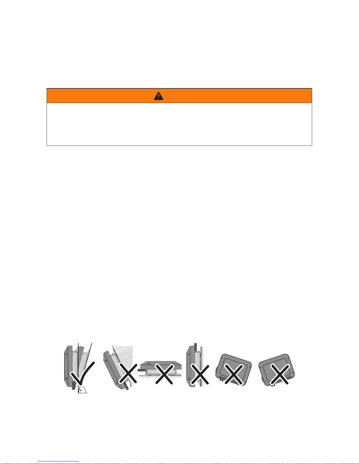
WARNING
Danger to life due to fire or explosion
Despite careful construction, electrical devices can cause fires.
• Do not mount the product in areas containing highly flammable materials or gases.
• Do not mount the product in potentially explosive atmospheres.
☐ Do not mount the inverter on a pillar.
☐ A solid, flat support surface,e.g. concrete or masonry, must be available for mounting. The
difference between the outer anchoring points must not exceed 5mm.
☐ The mounting location must be suitable for the weight and dimensions of the product (see
Section13 "Technical Data", page83).
☐ The mounting location must not be exposed to direct solar irradiation. If the product is
exposed to direct solar irradiation, the exterior plastic parts might age prematurely and
overheating might occur. When becoming too hot, the product reduces its power output to
avoid overheating.
☐ The mounting location should be freely and safely accessible at all times without the need for
any auxiliary equipment (such as scaffolding or lifting platforms). Non-fulfillment of these
criteria may restrict servicing.
☐ The DC load-break switch of the product must always be freely accessible.
☐ All ambient conditions must be met (see Section13, page83).
☐ To ensure optimum operation, the ambient temperature should be between -25°C and
+40°C.
Permitted and prohibited mounting positions:
☐ The product may only be mounted in a permitted position. This will ensure that no moisture can
penetrate the product.
☐ The product should be mounted such that the LED signals can be read off without difficulty.
15°
Figure 3: Permitted and prohibited mounting positions
5 Mounting
SMA Solar Technology AG
Operating manual SBxx-1VL-40-BE-en-13 21
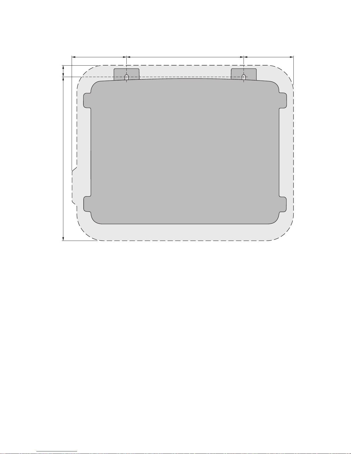
Dimensions for mounting:
115 105240
334
23
Figure 4: Position of the anchoring points(Dimensions in mm)
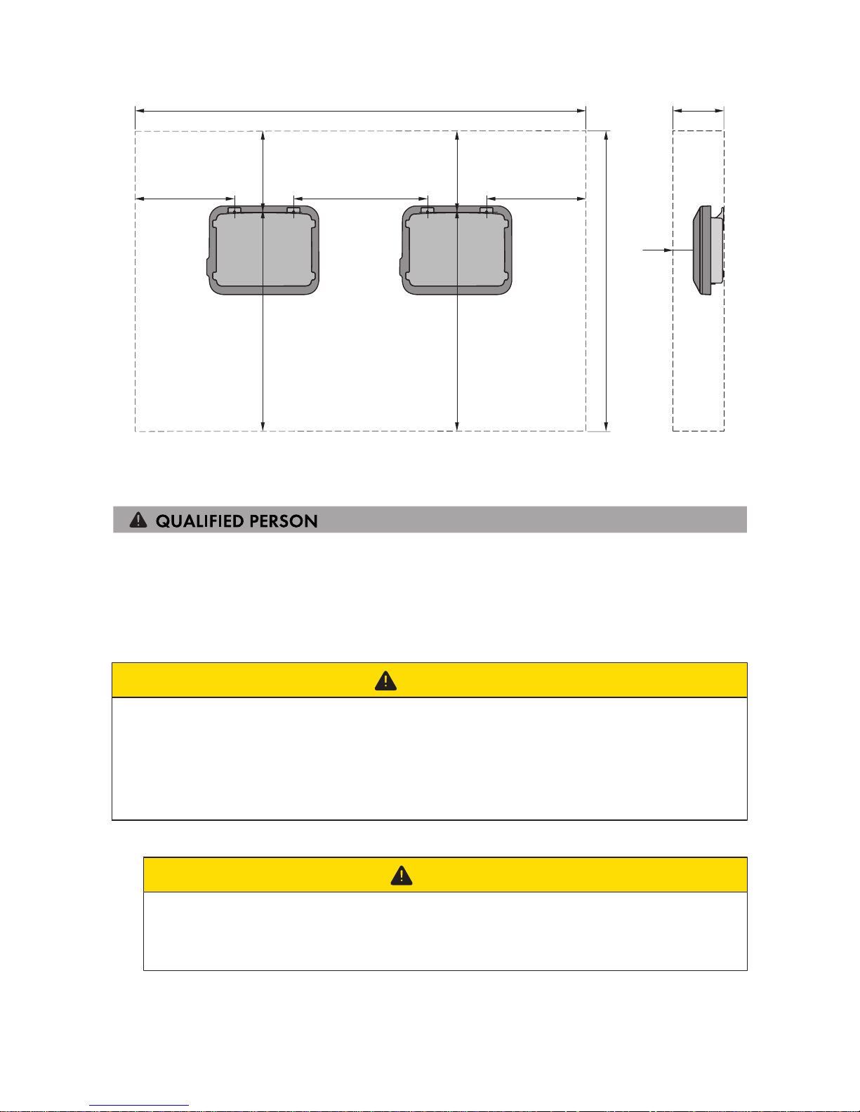
Recommended Clearances:
If you maintain the recommended clearances, adequate heat dissipation will be ensured. Thus, you
will prevent power reduction due to excessive temperature.
☐ Maintain the recommended clearances to walls as well as to other inverters or objects.
☐ If multiple inverters are mounted in areas with high ambient temperatures, increase the
clearances between the inverters and ensure sufficient fresh-air supply.
5 Mounting
SMA Solar Technology AG
Operating manualSBxx-1VL-40-BE-en-1322
1721755
985
350350 530
50
665
320
665
320
Figure 5: Recommended clearances(Dimensions in mm)
5.2 Mounting the Inverter
Additionally required material (not included in the scope of delivery):
☐ Two stainless steel hexagon head wood screws (AF10, diameter 6mm), screw length must be
suitable for the support surface and the weight of the inverter (fastening bracket thickness:
4mm)
☐ Where necessary, two screw anchors suitable for the support surface and the screws
CAUTION
Risk of injury due to weight of product
Injuries may result if the product is lifted incorrectly or dropped while being transported or when
attaching it to or removing it from the wall mounting bracket.
• Transport and lift the product carefully. Take the weight of the product into account.
• Wear suitable personal protective equipment for all work on the product.
Procedure:
1.
CAUTION
Risk of injury due to damaged cables
There may be power cables or other supply lines (e.g. gas or water) routed in the wall.
• Ensure that no lines are laid in the wall which could be damaged when drilling holes.
2. Mark the position of the drill holes. Align the markings horizontally.
3. Drill the holes.
5 Mounting
SMA Solar Technology AG
Operating manual SBxx-1VL-40-BE-en-13 23
4. Insert screw anchors into the drill holes if the support surface requires them.
5. When screwing the screws in, make sure that there is at least 6 mm left between the screw
head and the support surface.
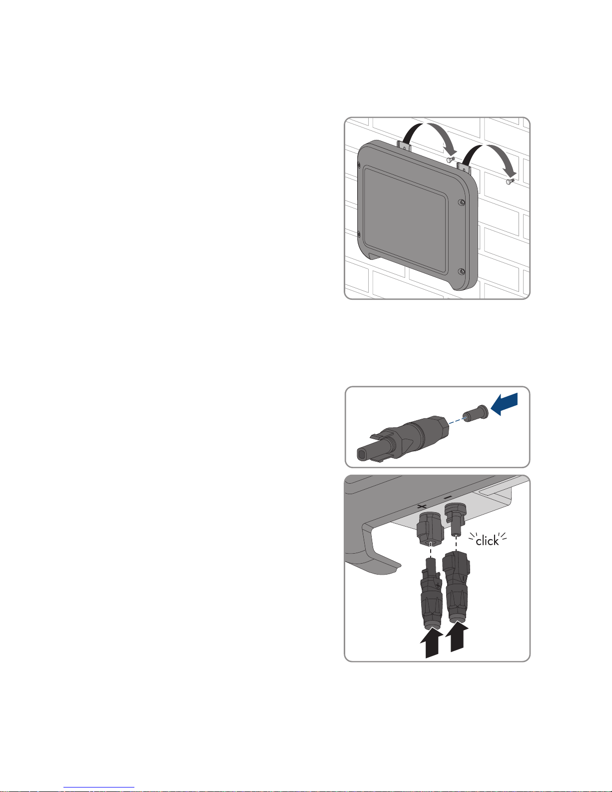
6. Hang the inverter onto the screws using the metal
brackets.
7. Tighten the screws hand-tight using a ratchet or box wrench. When doing this you can
compensate for any misalignment of the drill holes by aligning the metal brackets accordingly.
8. Ensure that the inverter is securely in place.
9. For unused DC connectors, push down the clamping bracket and push the swivel nut up to the
thread.
10. Insert the sealing plug into the DC connector.
+
11. Insert the DC connectors with sealing plugs into the
corresponding DC inputs on the inverter.
☑ The DC connectors snap into place.
12. Ensure that the DC connectors with sealing plugs are securely in place.
6 Electrical Connection
SMA Solar Technology AG
Operating manualSBxx-1VL-40-BE-en-1324
6 Electrical Connection
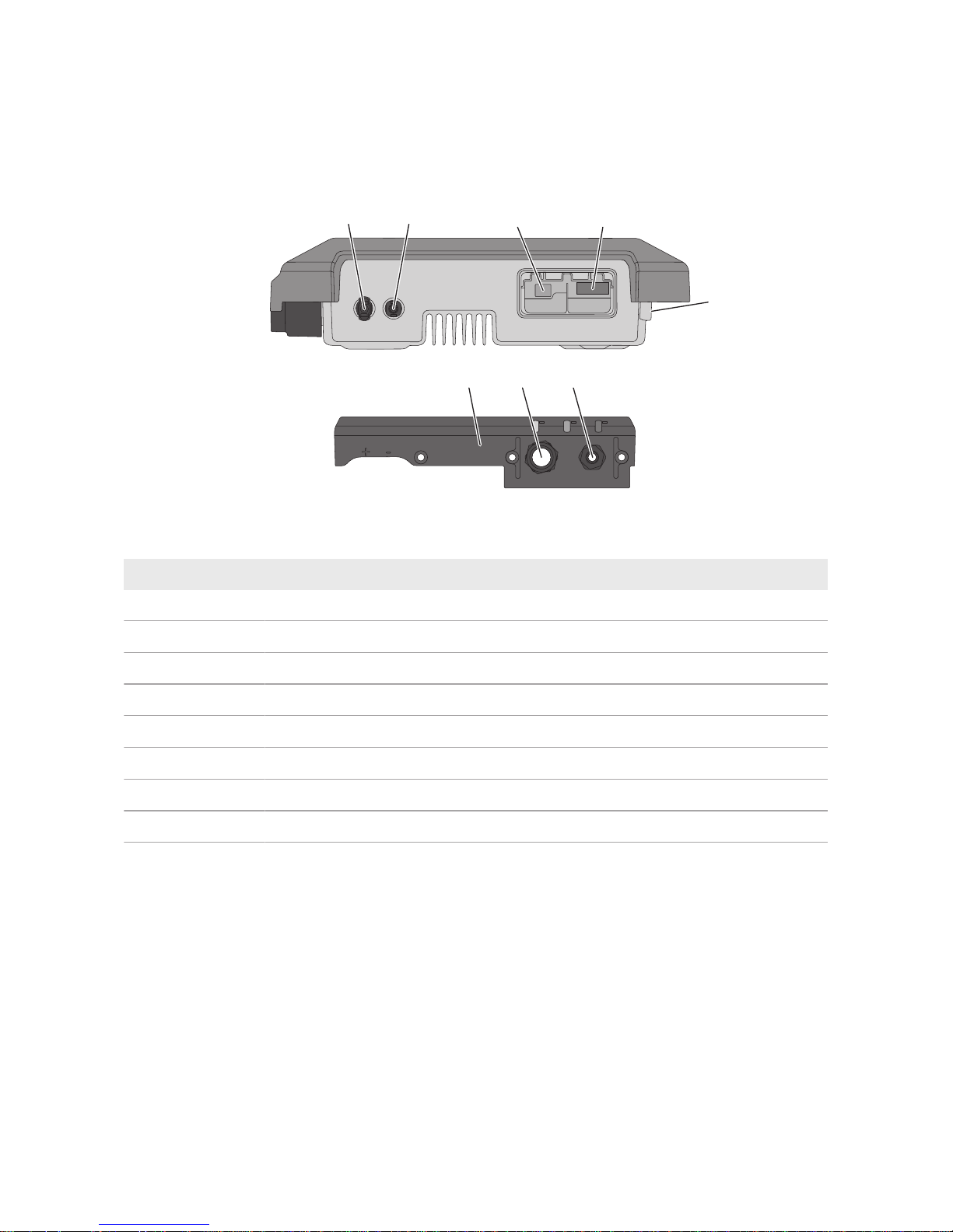
6.1 Overview of the Connection Area
CD
A
B
H
G
F
E
Figure 6: Connection areas and enclosure openings at the bottom of the inverter
Position Designation
A Positive DC connector
B Negative DC connector
C RJ45 pin connector for the network cable
D Pin connector for the AC connector
E Connection of the grounding terminal for additional grounding
F Cable gland for the AC cable
G Cable gland with filler plug for the network cable
H Connection cap

6 Electrical Connection
SMA Solar Technology AG
Operating manual SBxx-1VL-40-BE-en-13 25
6.2 AC Connection
6.2.1 Requirements for the AC Connection
Cable requirements:
☐ External diameter: 5mm to 13mm
☐ Conductor cross-section: 1.5mm² to 4mm²
☐ Insulation stripping length: 15mm
☐ Sheath stripping length: 70mm
☐ The cable must be dimensioned in accordance with the local and national directives for the
dimensioning of cables. The requirements for the minimum wire size derive from these
directives. Examples of factors influencing cable dimensioning are: nominal AC current, type of
cable, routing method, cable bundling, ambient temperature and maximum desired line losses
(for calculation of line losses, see the design software "SunnyDesign" from software
version2.0 at www.SMA-Solar.com).
Load-break switch and cable protection:
NOTICE
Damage to the inverter due to the use of screw-type fuses as load-break
switches
Screw-type fuses (e.g. DIAZED fuse or NEOZED fuse) are not load-break switches.
• Do not use screw-type fuses as load-break switches.
• Use a load-break switch or circuit breaker as a load disconnection unit (for information and
design examples, see the Technical Information "Circuit Breaker" at www.SMA-Solar.com).
☐ In PV systems with multiple inverters, protect each inverter with a separate circuit breaker.
Make sure to observe the maximum permissible fuse protection (see Section13 "Technical
Data", page83). This will prevent residual voltage from being present at the corresponding
cable after disconnection.
☐ Loads installed between the inverter and the circuit breaker must be fused separately.
Residual-current monitoring unit:
☐ If an external residual-current device is required, install a residual-current device which trips at
a residual current of 100mA or higher (for details on selecting a residual-current device, see
the Technical Information "Criteria for Selecting a Residual-Current Device" at www.SMASolar.com).
Overvoltage category:
The inverter can be used in grids of overvoltage categoryIII or lower in accordance with
IEC60664-1. That means that the inverter can be permanently connected to the grid-connection
point of a building. In case of installations with long outdoor cabling routes, additional measures to
reduce overvoltage categoryIV to overvoltage categoryIII are required (see the Technical
Information "Overvoltage Protection" at www.SMA-Solar.com).
6 Electrical Connection
SMA Solar Technology AG
Operating manualSBxx-1VL-40-BE-en-1326
Grounding conductor monitoring:
The inverter is equipped with a grounding conductor monitoring device. This grounding conductor
monitoring device detects when there is no grounding conductor connected and disconnects the
inverter from the utility grid if this is the case. Depending on the installation site and grid
configuration, it may be advisable to deactivate the grounding conductor monitoring. This is
necessary, for example, in an IT system or other grid configurations if there is no neutral conductor
present and you intend to install the inverter between two line conductors. If you are uncertain
about this, contact your grid operator or SMA Solar Technology AG.
• Grounding conductor monitoring must be deactivated after initial start-up depending on the
grid configuration (see Section8.14, page57).
Safety in accordance with IEC62109 when the grounding conductor
monitoring is deactivated
In order to guarantee safety in accordance with IEC62109 when the grounding conductor
monitoring is deactivated, you have to connect additional grounding:
• In order to guarantee safety in accordance with IEC62109 when the grounding
conductor monitoring is deactivated, you have to connect additional grounding (see
Section6.2.3, page28): The additional grounding conductor must have the same crosssection as the connected grounding conductor at the connecting terminal plate for the AC
cable. This prevents touch current if the grounding conductor at the connecting terminal
plate for the AC cable fails.
Connection of additional grounding
In some countries, additional grounding is generally required. In each case, observe the
locally applicable regulations.
• If additional grounding is required, connect an additional grounding that has at least the
same cross-section as the connected grounding conductor to the connecting terminal
plate for the AC cable (see Section6.2.3, page28). This prevents touch current if the
grounding conductor at the connecting terminal plate for the AC cable fails.
6.2.2 Connecting the Inverter to the Utility Grid
Requirements:
☐ Only the terminal block supplied may be used for the AC connection.
☐ The connection requirements of the grid operator must be met.
☐ The grid voltage must be within the permissible range. The exact operating range of the
inverter is specified in the operating parameters.
Procedure:
1. Disconnect the AC circuit breaker and secure it against reconnection.

6 Electrical Connection
SMA Solar Technology AG
Operating manual SBxx-1VL-40-BE-en-13 27
2. Unscrew the swivel nut from the cable gland for the
AC connection at the connector cap.
3. Thread the swivel nut over the AC cable.
4. Thread the AC cable through the cable gland of the AC connection:
• If the external diameter of the cable is 5mm to
7mm, thread the AC cable through the cable
gland directly.
• If the external diameter of the AC cable is
8mm to 13mm, first remove the inner sealing
ring from the cable gland and then thread the
AC cable through the cable gland. When
doing so, ensure that the outer sealing ring is
positioned correctly in the cable gland.
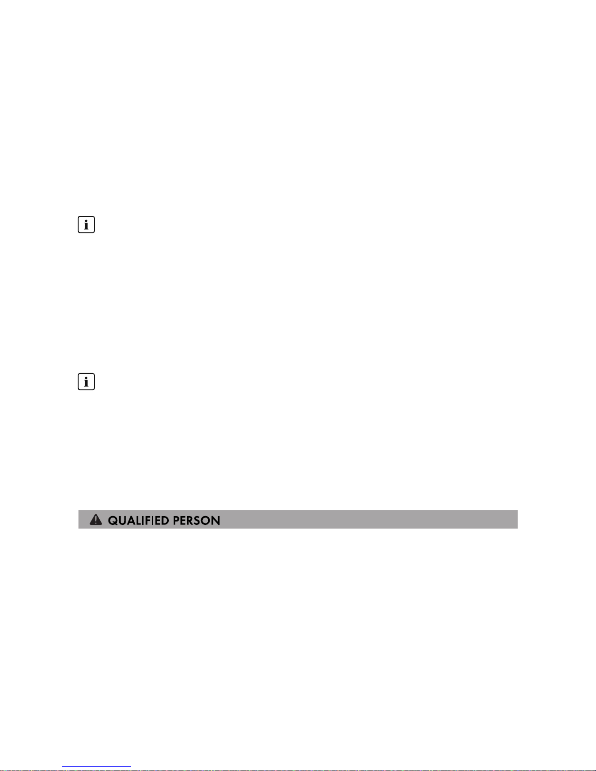
5. Dismantle 70mm of the AC cable.
6. Shorten L and N by 5mm each. Thus, the grounding conductor will be released from the
terminal block last when tensile load is applied.
7. Strip 15mm of the insulation of L, N and the grounding conductor.
6 Electrical Connection
SMA Solar Technology AG
Operating manualSBxx-1VL-40-BE-en-1328
8. Connect L, N and the grounding conductor to the
terminal block for the AC connection in accordance
with the labeling. When doing so, ensure that the
conductors are plugged completely into the
terminals up to the insulation. Tip: To release the
conductors from the terminals, the terminals must be
opened. To do this, stick a flat-blade screwdriver
(blade width: 3mm) as far as it can go into the
rectangular opening behind the terminal.
9. Ensure that all terminals are allocated to the correct conductors.
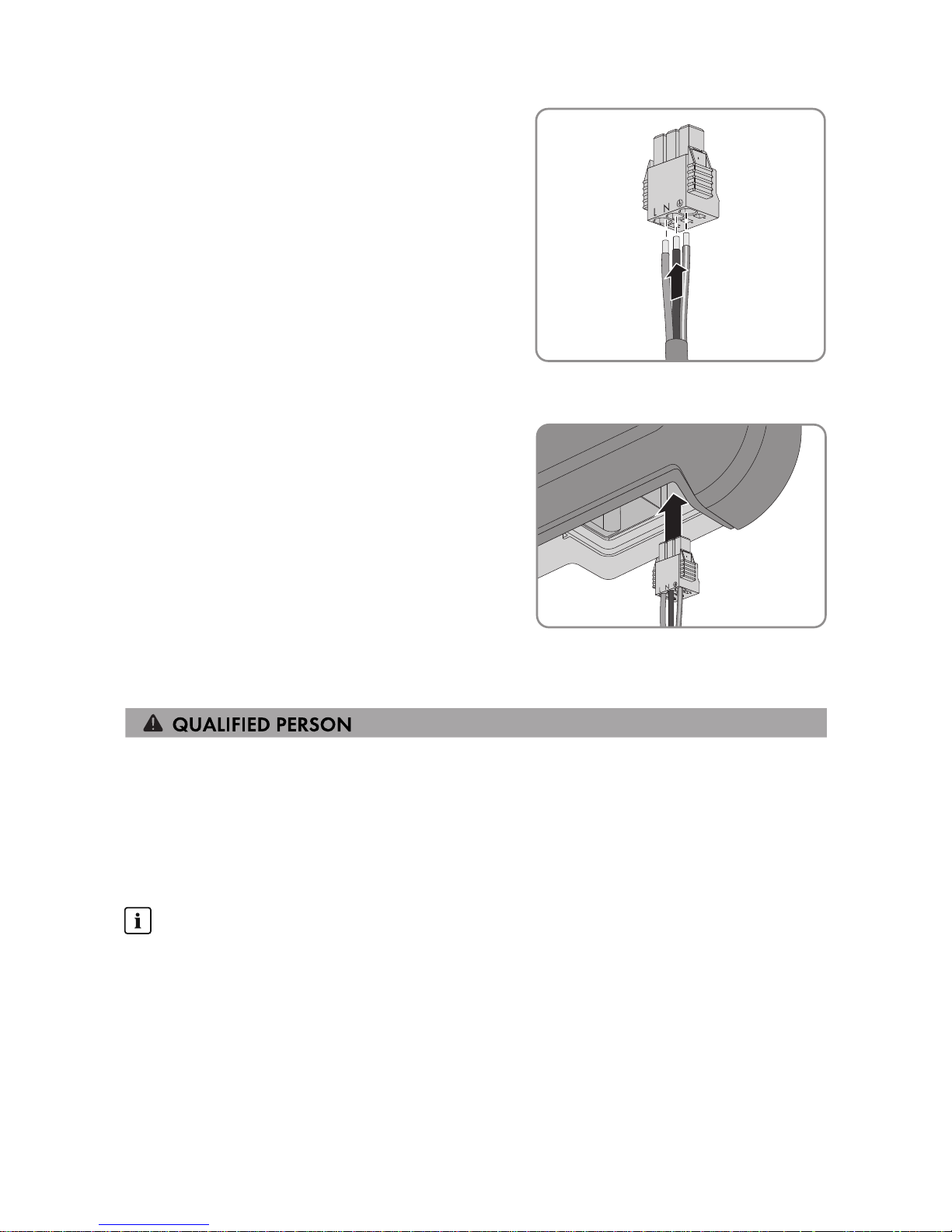
10. Make sure that all conductors are securely in place.
11. Plug the terminal block with the connected
conductors for the AC connection into the slot in the
inverter until the terminal block clicks into place.
12. Ensure that the terminal block is securely in place by slightly pulling it.
6.2.3 Connecting Additional Grounding
If additional grounding or equipotential bonding is required locally, you can connect additional
grounding to the inverter. This prevents touch current if the grounding conductor at the terminal for
the AC cable fails.
The required clamping bracket, the cylindrical screw M5x16, the washer and the spring lock
washer are part of the scope of delivery of the inverter.
Cable requirements:
Use of fine-stranded conductors
You can use an inflexible or a flexible, fine-stranded conductor.
• When using a fine-stranded conductor, it has to be double crimped by a ring terminal lug.
Make sure that no insulated conductor is visible when pulling or bending. This will ensure
sufficient strain relief by means of the ring terminal lug.
☐ Grounding cable cross-section: max. 10mm²
Procedure:
1. Strip off 12mm of the grounding cable insulation.
 Loading...