

Page 1
Installationsanleitung
Überspannungsschutz Set Ethernet für SMA String-
DEUTSCH
Monitore 3
InstallationManual
Ethernet overvoltage protection set for SMA String-
ENGLISH
Monitors 18
Instructionsd’installation
Jeu de protection contre les surtensions Ethernet pour le
FRANÇAIS
SMAString-Monitor 32
Instruccionesdeinstalación
Juego de protección contra sobretensión ethernet para
ESPAÑOL
SMA String-Monitor 47
Manualdeinstalação
Conjunto de protecção contra sobretensões Ethernet
PORTUGUÊS
para SMAString-Monitor 62
Istruzioniperl’installazione
Set di protezione da sovratensioni Ethernet per SMA
ITALIANO
String-Monitor 77
Instrucţiunideinstalare
Set de protecţie contra supratensiunii Ethernet pentru
ROMÂNĂ
aparatele SMA String-Monitor 91
SSMAbleitKomm-IA-xx-10 | 98-136200.01 | Version 1.0
Page 2

SMA Solar Technology AG
Οδηγίεςεγκατάστασης
Σετ προστασίας από υπέρταση Ethernet για SMAString-
ΕΛΛΗΝΙΚΑ
Monitor 106
설치매뉴얼
한국어
SMAString-Monitor용 이더넷 과전압 보호 세트 121
SSMAbleitKomm-IA-xx-102
Page 3

SMA Solar Technology AG
Inhaltsverzeichnis
Inhaltsverzeichnis
1 Hinweise zu diesem Dokument ............................................... 4
1.1 Gültigkeitsbereich............................................................................... 4
1.2 Zielgruppe .......................................................................................... 4
1.3 Symbole.............................................................................................. 4
1.4 Nomenklatur....................................................................................... 5
2 Sicherheit................................................................................... 5
2.1 Bestimmungsgemäße Verwendung................................................... 5
2.2 Sicherheitshinweise ............................................................................ 6
3 Lieferumfang ............................................................................. 6
4 Installation................................................................................. 8
4.1 Übersicht des Anschlussbereichs des SMA String-Monitors............ 8
4.2 Montageposition und Kabelweg ...................................................... 9
4.3 Überspannungsschutz für Ethernet-Kommunikation installieren ...... 10
5 Überspannungsschutz für Ethernet-Kommunikation
austauschen .............................................................................. 14
6 Überspannungsschutz für Ethernet-Kommunikation
deinstallieren............................................................................. 15
DEUTSCH
7 Fehlersuche ............................................................................... 16
8 Kontakt ...................................................................................... 17
Installationsanleitung 3SSMAbleitKomm-IA-xx-10
Page 4
DEUTSCH
1 Hinweise zu diesem Dokument
SMA Solar Technology AG
1 Hinweise zu diesem Dokument
1.1 Gültigkeitsbereich
Dieses Dokument gilt für den Gerätetyp "SSM-U-COMOVP" (Überspannungsschutz Set Ethernet für
SMA String-Monitore).
1.2 Zielgruppe
Die in diesem Dokument beschriebenen Tätigkeiten dürfen nur Fachkräfte durchführen. Fachkräfte
müssen über folgende Qualifikation verfügen:
• Kenntnis über Funktionsweise und Betrieb des Produkts
• Schulung im Umgang mit Gefahren und Risiken bei der Installation und Bedienung elektrischer
Geräte und Anlagen
• Ausbildung für die Installation und Inbetriebnahme von elektrischen Geräten und Anlagen
• Kenntnis der einschlägigen Normen und Richtlinien
• Kenntnis und Beachtung dieser Anleitung mit allen Sicherheitshinweisen
1.3 Symbole
Symbol Erklärung
Warnhinweis, dessen Nichtbeachtung unmittelbar zum Tod oder zu schwerer Verletzung führt
Warnhinweis, dessen Nichtbeachtung zum Tod
oder zu schwerer Verletzung führen kann
Warnhinweis, dessen Nichtbeachtung zu einer
leichten oder mittleren Verletzung führen kann
Warnhinweis, dessen Nichtbeachtung zu Sachschäden führen kann
Information, die für ein bestimmtes Thema oder
Ziel wichtig, aber nicht sicherheitsrelevant ist
Voraussetzung, die für ein bestimmtes Ziel gegeben sein muss
Erwünschtes Ergebnis
Möglicherweise auftretendes Problem
InstallationsanleitungSSMAbleitKomm-IA-xx-104
Page 5

SMA Solar Technology AG
2 Sicherheit
1.4 Nomenklatur
Vollständige Benennung Benennung in diesem Dokument
Überspannungsschutz Set Ethernet für SMA
String-Monitore
SMA String-Monitor • SMA String-Monitor
• Überspannungsschutz
• Produkt
• DC-Unterverteiler
2 Sicherheit
2.1 Bestimmungsgemäße Verwendung
Der Überspannungsschutz schützt die Ethernet-Verbindung vor Überspannung.
Der Überspannungsschutz darf nur in folgende Geräte von SMA Solar Technology AG eingebaut
werden:
• SMA String-Monitor:
– SSM-U-1610 / SSM-U-1615
– SSM-U-2410 / SSM-U-2415
– SSM-U-3210 / SSM-U-3215
Auch nach dem Einbau des Produkts bleibt die Normkonformität des SMA String-Monitors
weiterhin bestehen.
Alle Arbeiten am Produkt dürfen nur mit geeigneten Werkzeugen und unter Einhaltung der ESDSchutzvorschriften durchgeführt werden.
Setzen Sie das Produkt ausschließlich nach den Angaben der beigefügten Dokumentationen und
gemäß der vor Ort gültigen Normen und Richtlinien ein. Ein anderer Einsatz kann zu Personenoder Sachschäden führen.
Eingriffe in das Produkt, z. B. Veränderungen und Umbauten, sind nur mit ausdrücklicher
schriftlicher Genehmigung von SMA Solar Technology AG gestattet. Nicht autorisierte Eingriffe
führen zum Wegfall der Garantie- und Gewährleistungsansprüche sowie in der Regel zum
Erlöschen der Betriebserlaubnis. Die Haftung von SMA Solar Technology AG für Schäden aufgrund
solcher Eingriffe ist ausgeschlossen.
Jede andere Verwendung des Produkts als in der bestimmungsgemäßen Verwendung beschrieben
gilt als nicht bestimmungsgemäß.
Die beigefügten Dokumentationen sind Bestandteil des Produkts. Die Dokumentationen müssen
gelesen, beachtet und jederzeit zugänglich aufbewahrt werden.
DEUTSCH
Installationsanleitung 5SSMAbleitKomm-IA-xx-10
Page 6
DEUTSCH
3 Lieferumfang
SMA Solar Technology AG
2.2 Sicherheitshinweise
Lebensgefährlicher Stromschlag durch anliegende Spannung
An den spannungsführenden Bauteilen des DC-Unterverteilers liegen hohe Spannungen an. Das
Berühren spannungsführender Bauteile führt zum Tod oder zu schweren Verletzungen durch
Stromschlag.
• Bei allen Arbeiten geeignete persönliche Schutzausrüstung tragen.
• Keine spannungsführenden Bauteile berühren.
• Wenn anliegende Spannung nicht zwingend erforderlich ist, vor allen Arbeiten am DCUnterverteiler alle DC-Unterverteiler freischalten und den Wechselrichter DC-seitig
freischalten (siehe Anleitung des DC-Unterverteilers und des Wechselrichters).
Gefahr eines Sachschadens durch Verwenden eines defekten Überspannungsschutzes
für Kommunikation
Ein defekter Überspannungsschutz bietet keinen Schutz mehr vor Überspannung. Die über die
Datenkabel verbundenen Geräte können im Falle einer Überspannung beschädigt werden.
• Defekten Überspannungsschutz austauschen.
Ein Defekt kann unter anderem vorliegen, wenn die Kommunikationsverbindung
unterbrochen ist.
3 Lieferumfang
Prüfen Sie den Lieferumfang auf Vollständigkeit und äußerlich sichtbare Beschädigungen. Setzen
Sie sich bei unvollständigem Lieferumfang oder Beschädigungen mit Ihrem Fachhändler in
Verbindung.
InstallationsanleitungSSMAbleitKomm-IA-xx-106
Page 7
SMA Solar Technology AG
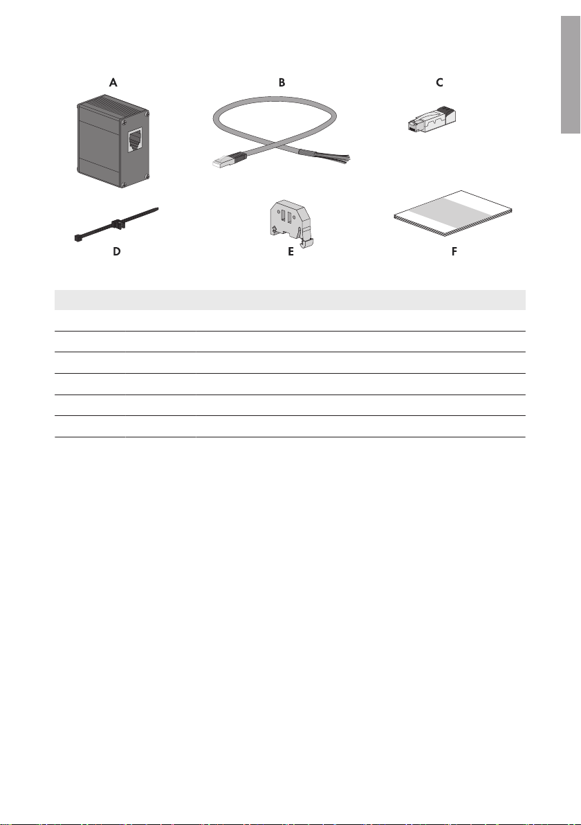
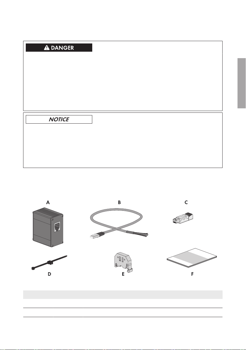
Abbildung 1 : Bestandteile des Lieferumfangs
Position Anzahl Bezeichnung
A 1 Überspannungsableiter Typ 2 für Kommunikation
B 1 Vorkonfektioniertes Ethernet-Kabel mit einem RJ45-Stecker
C 1 RJ45-Steckverbinder
D 1 Befestigungsbinder
E 1 Endklammer
F 1 Installationsanleitung
3 Lieferumfang
DEUTSCH
Installationsanleitung 7SSMAbleitKomm-IA-xx-10
Page 8

DEUTSCH
4 Installation
SMA Solar Technology AG
4 Installation
4.1 Übersicht des Anschlussbereichs des SMA StringMonitors
Unteransicht
Abbildung 2 : Unteransicht des SMA String-Monitors
Position Bezeichnung
A Gehäuseöffnung mit Kabelverschraubung für die Hauptkabel DC+
B Gehäuseöffnung mit String-Kabelbäumen (PV+) und DC-Steckverbindern (werksei-
tig vormontiert)
C Kondensatablauf
D Gehäuseöffnung mit String-Kabelbäumen (PV‒) und DC-Steckverbindern (werksei-
tig vormontiert)
E Gehäuseöffnung mit Kabelverschraubung für die Hauptkabel DC‒
F Gehäuseöffnung mit Membran für folgende Kabel:
• Kommunikation
• Sensorik
• Externe Funktionserde für die Elektronikbaugruppe
• Externe Funktionserde für den DC-Überspannungsableiter
G Gehäuseöffnung mit Kabelverschraubung für die Kabel der externen 230VAC-
Spannungsversorgung
H Gehäuseöffnung mit Kabelverschraubung für das Kabel der externen Funktionserde
des AC-Piggy-Backs
InstallationsanleitungSSMAbleitKomm-IA-xx-108
Page 9
SMA Solar Technology AG
4 Installation
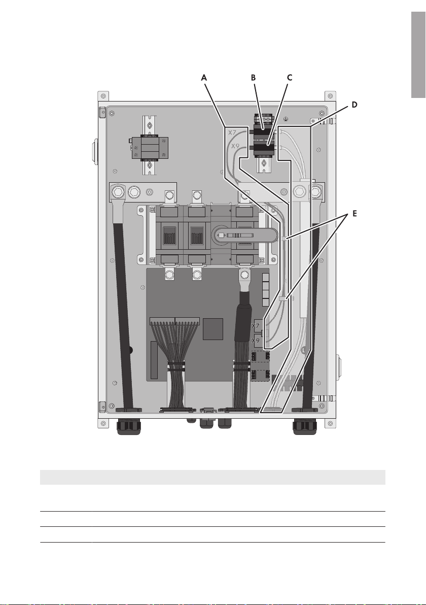
4.2 Montageposition und Kabelweg
DEUTSCH
Abbildung 3 : Montageposition und Kabelweg des Überspannungsableiters im SMA String-Monitor SSM-UXX10 (Beispiel)
Position Bezeichnung
A Kabelweg für die Kabel zwischen der Elektronikbaugruppe und den Überspan-
nungsableitern
B Montageposition des Überspannungsableiters für den Kommunikationsausgang
C Montageposition des Überspannungsableiter für den Kommunikationseingang
Installationsanleitung 9SSMAbleitKomm-IA-xx-10
Page 10

DEUTSCH
4 Installation
Position Bezeichnung
D Kabelweg für die Kabel zwischen anderen Geräten im Kommunikationsbus und
den Überspannungsableitern
E Kabellaschen
SMA Solar Technology AG
4.3 Überspannungsschutz für Ethernet-Kommunikation installieren
Die Netzwerkkabel für die Ethernet-Kommunikation werden von SMA String-Monitor zu SMA
String-Monitor bis zum Wechselrichter geführt. Für den Ethernet-Kommunikationsausgang und den
Ethernet-Kommunikationseingang wird jeweils ein Überspannungsschutz im SMA String-Monitor
benötigt.
Lebensgefährlicher Stromschlag durch anliegende Spannung
An den spannungsführenden Bauteilen des DC-Unterverteilers liegen hohe Spannungen an. Das
Berühren spannungsführender Bauteile führt zum Tod oder zu schweren Verletzungen durch
Stromschlag.
• Den Wechselrichter DC-seitig freischalten (siehe Anleitung des Wechselrichters).
• Den DC-Unterverteiler freischalten (siehe Anleitung des DC-Unterverteilers).
• Alle im DC-Anschlussbereich des Wechselrichters parallel geschalteten DC-Unterverteiler
freischalten (siehe Anleitung des jeweiligen DC-Unterverteilers).
Sachschäden durch eindringenden Staub oder Feuchtigkeit
Durch unnötige oder zu große Löcher in den Membranen der Kabeldurchführungsplatte können
Staub oder Feuchtigkeit in den DC-Unterverteiler eindringen.
• In der Kabeldurchführungsplatte nur so viele Membrane durchstoßen, wie Kabel benötigt
werden.
• Das Loch in der Membran muss kleiner sein als das durchzuführende Kabel.
Störung der Datenübertragung durch ungeschirmte Energiekabel
Ungeschirmte Energiekabel erzeugen im Betrieb ein elektromagnetisches Feld, das die
Datenübertragung von Netzwerkkabeln stören kann.
• Beim Verlegen von Netzwerkkabeln folgende Mindestabstände zu ungeschirmten
Energiekabeln einhalten:
– Bei Verlegung ohne Trennsteg: mindestens 200mm
– Bei Verlegung mit Trennsteg aus Aluminium: mindestens 100mm
– Bei Verlegung mit Trennsteg aus Stahl: mindestens 50mm
Anforderungen an Ethernet-Kabel:
☐ Kabelart: Kupfer-Doppelader
InstallationsanleitungSSMAbleitKomm-IA-xx-1010
Page 11
SMA Solar Technology AG
4 Installation
☐ Anzahl der Aderpaare und Aderquerschnitt: 4 x 2 x 0,125mm2 … 0,205mm
2
☐ Kabeltyp: mindestens Cat5 mit Schirmung S-UTP, F-UTP oder höher
☐ Maximale Kabellänge: 100m
☐ Die RJ45-Steckverbinder müssen gemäß EIA/TIA 568B (achtadrig) angeschlossen werden:
Signal Anschluss
X7 und X9
TX+ 1
EIA/TIA 568B (achtadrig)
Aderfarbe
weiß/orange
(weiß/orange)
TX- 2
orange/weiß oder orange
(orange/weiß oder orange)
RX+ 3
weiß/grün
(weiß/grün)
nicht belegt 4
blau/weiß oder blau
(blau/weiß oder blau)
nicht belegt 5
weiß/blau
(weiß/blau)
RX- 6
grün/weiß oder grün
(grün/weiß oder grün)
nicht belegt 7
weiß/braun
(weiß/braun)
nicht belegt 8
braun/weiß oder braun
(braun/weiß oder braun)
DEUTSCH
Vorgehen:
1. Den Wechselrichter DC-seitig freischalten (siehe Anleitung des Wechselrichters).
2. Den SMA String-Monitor freischalten (siehe Anleitung des SMA String-Monitors).
3. Die Schutzabdeckungen des SMA String-Monitors demontieren (siehe Anleitung des SMA
String-Monitors).
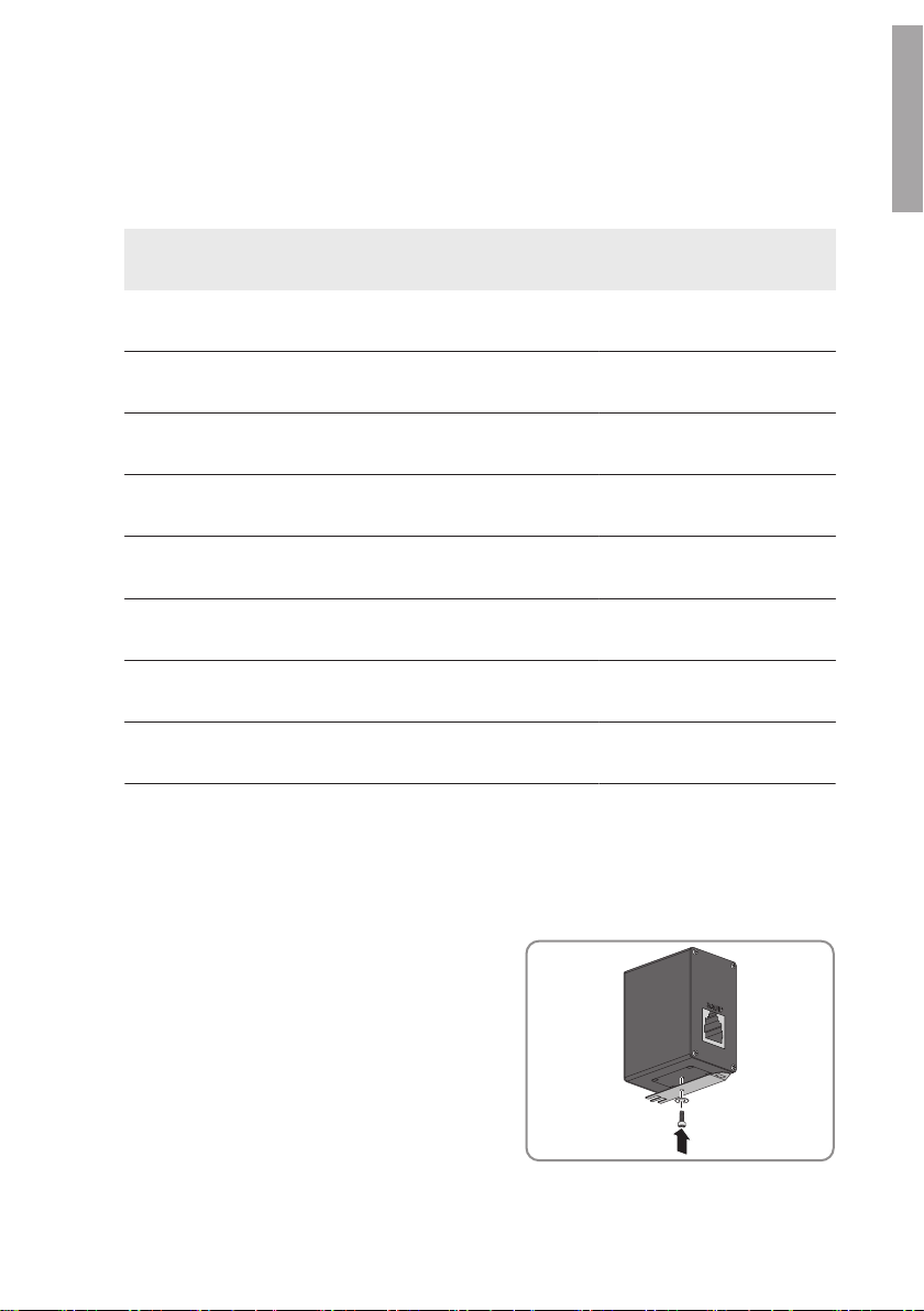
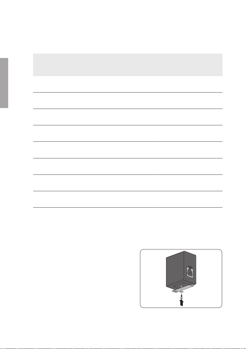
4. An der Unterseite des Überspannungsschutzes
den Hutschienenträger mit der Unterlegscheibe
und der Schraube befestigen. Dabei muss die
Lasche des Hutschienenträgers zur Seite des
Überspannungsschutzes mit der Aufschrift
EQUIP zeigen.
5. Für den Kommunikationsausgang und bei Bedarf für den Kommunikationseingang jeweils
einen Überspannungsschutz installieren:
Installationsanleitung 11SSMAbleitKomm-IA-xx-10
Page 12

DEUTSCH
4 Installation
SMA Solar Technology AG
• Den Überspannungsschutz auf der Hutschiene montieren. Dabei die Montageposition
beachten (siehe Kapitel4.2, Seite9). Der Anschluss EQUIP muss nach links zeigen.
• Die Endklammer bündig über bzw. unter dem Überspannungsschutz auf die Hutschiene
klemmen.
☑ Die Endklammer rastet hörbar ein und der Überspannungsschutz kann nicht mehr
auf der Hutschiene verschoben werden.
6. Um den Kommunikationsausgang am Überspannungsschutz für den Kommunikationsausgang
anzuschließen:
• Den RJ45-Stecker des mitgelieferten Ethernet-Kabels in den Überspannungsschutz in den
Anschluss EQUIP stecken.
• Das andere Ende des Ethernet-Kabels an der String-Monitor Unit am Anschluss X7
gemäß Schaltplan anschließen. Dabei den Kabelweg beachten (siehe Kapitel4.2, Seite
9).
• Das Ethernet-Kabel mit den Kabellaschen im SMA String-Monitor befestigen (siehe
Kapitel4.2, Seite9).
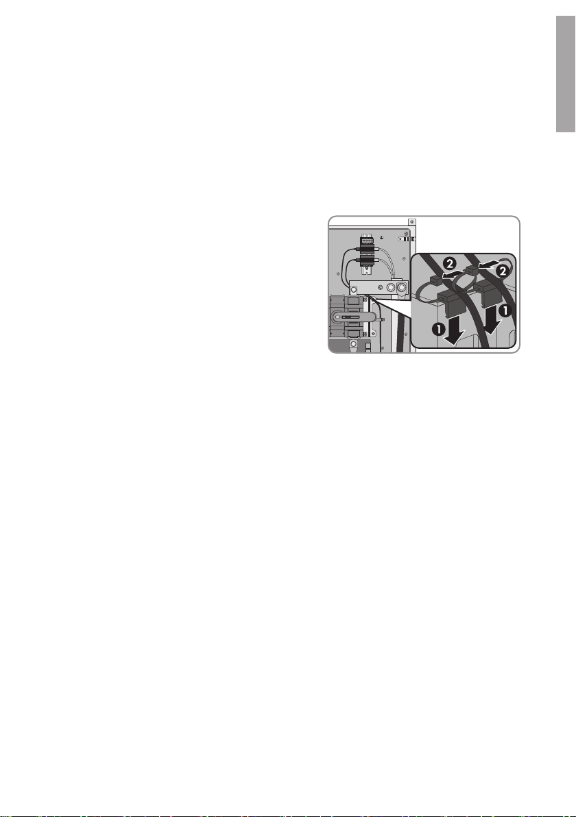
• Den Befestigungsbinder auf die Halterung
des DC-Lastrennschalters stecken und das
Ethernet-Kabel mit dem Kabelbinder
fixieren.
• Das Ethernet-Kabel für den Kommunikationsausgang durch die entsprechende
Kabeldurchführung (siehe Kapitel4.1, Seite8) in den SMA String-Monitor führen. Dabei
die entsprechende Membran durchstoßen und das Ethernet-Kabel durch die Membran
hindurch schieben.
• Den RJ45-Steckverbinder am eingeführten Ende des Ethernet-Kabels gemäß EIA/TIA
568B (achtadrig) anschließen (siehe Anleitung des RJ45-Steckverbinders). Dabei darauf
achten, dass keine Kabelreste in den SMA String-Monitor fallen.
• Das Ethernet-Kabel gemäß Kabelweg (siehe Kapitel4.2, Seite9) im Kabelkanal zum
Überspannungsschutz führen. Dabei die Abdeckung des Kabelkanals entfernen, das
Ethernet-Kabel einlegen und die Abdeckung wieder befestigten.
• Den RJ45-Steckverbinder in den Überspannungsschutz in den Anschluss LINE IN
stecken.
• Um das Ethernet-Kabel im nächsten SMA String-Monitor im Kommunikationsbus
anzuschließen, das andere Ende des Ethernet-Kabels im nächsten SMA String-Monitor in
den Überspannungsschutz für den Kommunkationseingang in den Anschluss LINE IN
stecken.
• Um das Ethernet-Kabel im Wechselrichter anzuschließen, siehe Anleitung des
Wechselrichters.
InstallationsanleitungSSMAbleitKomm-IA-xx-1012
Page 13
SMA Solar Technology AG
4 Installation
7. Um den Kommunikationseingang am Überspannungsschutz für den Kommunikationseingang
anzuschließen:
• Den RJ45-Stecker des mitgelieferten Ethernet-Kabels in den Überspannungsschutz in den
Anschluss EQUIP stecken.
• Das andere Ende des Ethernet-Kabels an der String-Monitor Unit am Anschluss X9
gemäß Schaltplan anschließen. Dabei den Kabelweg beachten (siehe Kapitel4.2, Seite
9).
• Das Ethernet-Kabel mit den Kabellaschen im SMA String-Monitor befestigen (siehe
Kapitel4.2, Seite9).
• Den Befestigungsbinder auf die Halterung
des DC-Lastrennschalters stecken und das
Ethernet-Kabel mit dem Kabelbinder
fixieren.
• Das Ethernet-Kabel für den Kommunikationseingang durch die entsprechende
Kabeldurchführung (siehe Kapitel4.1, Seite8) in den SMA String-Monitor führen. Dabei
die entsprechende Membran durchstoßen und das Ethernet-Kabel durch die Membran
hindurch schieben.
• Den RJ45-Steckverbinder am eingeführten Ende des Ethernet-Kabels gemäß EIA/TIA
568B (achtadrig) anschließen (siehe Anleitung des RJ45-Steckverbinders). Dabei darauf
achten, dass keine Kabelreste in den SMA String-Monitor fallen.
• Das Ethernet-Kabel gemäß Kabelweg (siehe Kapitel4.2, Seite9) im Kabelkanal zum
Überspannungsschutz führen. Dabei die Abdeckung des Kabelkanals entfernen, das
Kabel einlegen und die Abdeckung wieder befestigten.
• Den RJ45-Steckverbinder in den Überspannungsschutz in den Anschluss LINE IN
stecken.
8. Die Schutzabdeckungen des SMA String-Monitors wieder montieren (siehe Anleitung des
SMA String-Monitors).
9. Den SMA String-Monitor wieder zuschalten (siehe Anleitung des SMA String-Monitors).
DEUTSCH
Installationsanleitung 13SSMAbleitKomm-IA-xx-10
Page 14
DEUTSCH
5 Überspannungsschutz für Ethernet-Kommunikation austauschen
SMA Solar Technology AG
5 Überspannungsschutz für Ethernet-Kommunikation
austauschen
Lebensgefährlicher Stromschlag durch anliegende Spannung
An den spannungsführenden Bauteilen des DC-Unterverteilers liegen hohe Spannungen an. Das
Berühren spannungsführender Bauteile führt zum Tod oder zu schweren Verletzungen durch
Stromschlag.
• Den Wechselrichter DC-seitig freischalten (siehe Anleitung des Wechselrichters).
• Den DC-Unterverteiler freischalten (siehe Anleitung des DC-Unterverteilers).
• Alle im DC-Anschlussbereich des Wechselrichters parallel geschalteten DC-Unterverteiler
freischalten (siehe Anleitung des jeweiligen DC-Unterverteilers).
Zusätzlich benötigtes Material (nicht im Lieferumfang enthalten):
☐ 1 bis 2 Überspannungsschutze, je nach Anzahl der auszutauschenden Überspannungsschutze
(SMA-Bestellnummer siehe Anleitung des SMA String-Monitors)
Vorgehen:
1. Den Wechselrichter DC-seitig freischalten (siehe Anleitung des Wechselrichters).
2. Den SMA String-Monitor freischalten (siehe Anleitung des SMA String-Monitors).
3. Die Schutzabdeckungen des SMA String-Monitors demontieren (siehe Anleitung des SMA
String-Monitors).
4. Am Überspannungsschutz die RJ45-Stecker aus den Anschlüssen EQUIP und LINE IN
entfernen.
5. Die Abschlussklemme von der Hutschiene entfernen.
6. Den Überspannungsschutz mit Hilfe des Hutschienenträgers von der Hutschiene abnehmen.
7. Um die Kabel des Überspannungsschutzes auszutauschen:
• An der Baugruppe das Kabel des Überspannungsschutzes am Anschluss X7 bzw. X9
entfernen.
• Den Befestigungsbinder des Kabels lösen und das Kabel aus dem SMA String-Monitor
entfernen.
• Das andere Kabel aus dem Kabelkanal entfernen. Dabei die Abdeckung des
Kabelkanals entfernen, das Kabel herausnehmen und die Abdeckung wieder befestigten.
• Den RJ45-Stecker am Kabel entfernen. Dabei darauf achten, dass keine Kabelreste in
den SMA String-Monitor fallen.
• Das Kabel durch die Membran aus dem SMA String-Monitor ziehen.
8. Den neuen Überspannungsschutz installieren (siehe Kapitel4.3, Seite10).
InstallationsanleitungSSMAbleitKomm-IA-xx-1014
Page 15

SMA Solar Technology AG
6 Überspannungsschutz für Ethernet-Kommunikation deinstallieren
6 Überspannungsschutz für Ethernet-Kommunikation
deinstallieren
Die Deinstallation ist am Beispiel eines SMA String-Monitors mitten im Kommunikationsbus, mit 2
Überspannungsschutzen (Kommunikationsausgang und Kommunikationseingang) für EthernetKommunikation beschrieben.
Lebensgefährlicher Stromschlag durch anliegende Spannung
An den spannungsführenden Bauteilen des DC-Unterverteilers liegen hohe Spannungen an. Das
Berühren spannungsführender Bauteile führt zum Tod oder zu schweren Verletzungen durch
Stromschlag.
• Den Wechselrichter DC-seitig freischalten (siehe Anleitung des Wechselrichters).
• Den DC-Unterverteiler freischalten (siehe Anleitung des DC-Unterverteilers).
• Alle im DC-Anschlussbereich des Wechselrichters parallel geschalteten DC-Unterverteiler
freischalten (siehe Anleitung des jeweiligen DC-Unterverteilers).
Zusätzlich benötigtes Material (nicht im Lieferumfang enthalten):
☐ 2 bis 4 Stopfen zum Abdichten der jeweiligen Membran-Öffnung:
• Für Membran-Öffnungen mit Durchmesser 3,2mm … 6,5mm: Stopfen mit Durchmesser 6mm,
erhältlich bei www.icotek.com.
• Für Membran-Öffnungen mit Durchmesser 5,0mm … 10,2mm: Stopfen mit Durchmesser
10mm, erhältlich bei www.icotek.com.
Vorgehen:
1. Den Wechselrichter DC-seitig freischalten (siehe Anleitung des Wechselrichters).
2. Den SMA String-Monitor freischalten (siehe Anleitung des SMA String-Monitors).
3. Die Schutzabdeckungen des SMA String-Monitors demontieren (siehe Anleitung des SMA
String-Monitors).
4. An der Baugruppe die Kabel an den Anschlüssen X7 und X9 entfernen.
5. An den Überspannungsschutzen die Kabel an den Anschlüssen EQUIP entfernen, die
Befestigungsbinder lösen und die Kabel aus dem SMA String-Monitor entfernen.
6. An den Überspannungsschutzen die Kabel an den Anschlüssen LINE IN entfernen, die Kabel
aus dem Kabelkanal entfernen. Dabei die Abdeckung des Kabelkanals entfernen, die Kabel
herausnehmen und die Abdeckung wieder befestigen.
7. Die RJ45-Steckverbinder von den Kabeln entfernen. Dabei darauf achten, dass keine
Kabelreste in den SMA String-Monitor fallen.
8. Die Kabel durch die Membran aus dem SMA String-Monitor ziehen.
9. Mit den Stopfen die Membran-Öffnungen verschließen.
10. Die Abschlussklemmen und die Überspannungsschutze von der Hutschiene demontieren und
aus dem SMA String-Monitor entfernen.
DEUTSCH
Installationsanleitung 15SSMAbleitKomm-IA-xx-10
Page 16
DEUTSCH
7 Fehlersuche
11. Die Schutzabdeckungen des SMA String-Monitors wieder montieren (siehe Anleitung des
SMA String-Monitors).
12. Bei Bedarf den SMA String-Monitor wieder zuschalten (siehe Anleitung des SMA StringMonitors).
13. Den SMA String-Monitor schließen.
SMA Solar Technology AG
7 Fehlersuche
Lebensgefährlicher Stromschlag durch anliegende Spannung
An den spannungsführenden Bauteilen des DC-Unterverteilers liegen hohe Spannungen an. Das
Berühren spannungsführender Bauteile führt zum Tod oder zu schweren Verletzungen durch
Stromschlag.
• Bei allen Arbeiten geeignete persönliche Schutzausrüstung tragen.
• Keine spannungsführenden Bauteile berühren.
• Wenn anliegende Spannung nicht zwingend erforderlich ist, vor allen Arbeiten am DCUnterverteiler alle DC-Unterverteiler freischalten und den Wechselrichter DC-seitig
freischalten (siehe Anleitung des DC-Unterverteilers und des Wechselrichters).
InstallationsanleitungSSMAbleitKomm-IA-xx-1016
Page 17

SMA Solar Technology AG
8 Kontakt
Problem Ursache und Abhilfe
Der SMA String-Monitor ist nicht erreichbar.
Möglicherweise ist der Überspannungsschutz defekt oder wurde durch
eine zu hohe Überspannung zerstört.
Abhilfe:
• Prüfen, ob die Kommunikationsverbindung durch den
Überspannungsschutz unterbrochen wird.
Wenn die Kommunikationsverbindung durch den
Überspannungsschutz unterbrochen wird, ist der
Überspannungsschutz defekt. Möglicherweise durch eine
Überspannung zB. durch einen Blitzeinschlag. Folgende Schritte
durchführen:
– Den Überspannungsschutz austauschen (siehe Kapitel5, Seite14
).
– Die Baugruppe auf sichtbare Schäden prüfen, z.B.
verschmorte Teile und Verbindungen. Wenn die Baugruppe
beschädigt ist, Service kontaktieren (siehe Kapitel8, Seite17).
– Die Ethernet-Kabel auf sichtbare Schäden prüfen, z.B.
verschmorte Stellen am Kabelmantel. Wenn Ethernet-Kabel
beschädigt sind, die Ethernet-Kabel austauschen (siehe
Kapitel5, Seite14).
Die Ethernet-Verbindung ist nicht korrekt eingerichtet.
Abhilfe:
• Auf der Benutzeroberfläche des Wechselrichters die
Netzwerkverbindung bis zum SMA String-Monitor prüfen (siehe
Anleitung des Wechselrichters).
• Sicherstellen, dass alle Stecker der Ethernet-Kabel gesteckt und
verriegelt sind.
• Sicherstellen, dass der Router/Switch der Anlage eingeschaltet ist.
• Sicherstellen, dass alle DC-Unterverteiler im Kommunikationsbus
betriebsbereit sind.
DEUTSCH
8 Kontakt
Kontaktdaten finden Sie unter www.SMA-Solar.com.
Installationsanleitung 17SSMAbleitKomm-IA-xx-10
Page 18

ENGLISH
Table of Contents
SMA Solar Technology AG
Table of Contents
1 Information on this Document ................................................. 19
1.1 Validity................................................................................................ 19
1.2 Target Group...................................................................................... 19
1.3 Symbols .............................................................................................. 19
1.4 Nomenclature..................................................................................... 20
2 Safety......................................................................................... 20
2.1 Intended Use ...................................................................................... 20
2.2 Safety Information.............................................................................. 21
3 Scope of Delivery...................................................................... 21
4 Installation................................................................................. 22
4.1 Overview of the Connection Area of the SMA String-Monitor....... 22
4.2 Mounting Position and Cable Route................................................. 24
4.3 Installing Overvoltage Protection for Ethernet Communication....... 25
5 Replacing the Overvoltage Protection Unit for Ethernet
Communication ......................................................................... 28
6 Deinstalling the Overvoltage Protection Unit for Ethernet
Communication ......................................................................... 29
7 Troubleshooting........................................................................ 30
8 Contact....................................................................................... 31
Installation ManualSSMAbleitKomm-IA-xx-1018
Page 19

SMA Solar Technology AG
1 Information on this Document
1 Information on this Document
1.1 Validity
This document is valid for the device type "SSM-U-COMOVP" (Ethernet overvoltage protection set
for SMA String-Monitors).
1.2 Target Group
The tasks described in this document must only be performed by qualified persons. Qualified
persons must have the following skills:
• Knowledge of how the product works and is operated
• Training in how to deal with the dangers and risks associated with installing and using
electrical devices and systems
• Training in the installation and commissioning of electrical devices and systems
• Knowledge of all applicable standards and directives
• Knowledge of and adherence to this manual and all safety precautions
1.3 Symbols
Symbol Explanation
Indicates a hazardous situation which, if not
avoided, will result in death or serious injury
Indicates a hazardous situation which, if not
avoided, can result in death or serious injury
Indicates a hazardous situation which, if not
avoided, can result in minor or moderate injury
Indicates a situation which, if not avoided, can
result in property damage
Information that is important for a specific topic
or goal, but is not safety-relevant
Indicates a requirement for meeting a specific
goal
Desired result
A problem that might occur
ENGLISH
Installation Manual 19SSMAbleitKomm-IA-xx-10
Page 20

ENGLISH
2 Safety
SMA Solar Technology AG
1.4 Nomenclature
Complete designation Designation in this document
Ethernet overvoltage protection set for SMA
String-Monitors
SMA String-Monitor • SMA String-Monitor
• Overvoltage protection
• Product
• DC sub-distribution
2 Safety
2.1 Intended Use
The overvoltage protection unit protects the Ethernet connection from surge voltage.
The overvoltage protection unit is only permitted for installation in the following SMA Solar
Technology AG devices:
• SMA String-Monitor:
– SSM-U-1610/SSM-U-1615
– SSM-U-2410/SSM-U-2415
– SSM-U-3210/SSM-U-3215
The SMA String-Monitor still complies with the applicable standards after the product has been
installed.
All work on the product must only be performed using appropriate tools and in compliance with the
ESD protection regulations.
Use this product only in accordance with the information provided in the enclosed documentation
and with the locally applicable standards and directives. Any other application may cause
personal injury or property damage.
Alterations to the product, e.g. changes or modifications, are only permitted with the express written
permission of SMA Solar Technology AG. Unauthorized alterations will void guarantee and
warranty claims and usually void the operating license. SMA Solar Technology AG shall not be
held liable for any damage caused by such changes.
Any use of the product other than that described in the Intended Use section does not qualify as
appropriate.
The enclosed documentation is an integral part of this product. Keep the documentation in a
convenient place for future reference and observe all instructions contained therein.
Installation ManualSSMAbleitKomm-IA-xx-1020
Page 21
SMA Solar Technology AG
3 Scope of Delivery
2.2 Safety Information
Danger to life from electric shock due to live voltage
High voltages are present in the live components of the DC sub-distribution. Touching live
components results in death or serious injury due to electric shock.
• Wear suitable personal protective equipment for all work on the product.
• Do not touch any live components.
• If live voltage is not absolutely necessary, disconnect all DC sub-distributions before working
on the DC sub-distribution and disconnect the inverter on the DC side (see manual of the DC
sub-distribution and of the inverter).
Risk of property damage through use of defective overvoltage protection unit for
communication
A defective overvoltage protection unit no longer affords protection from surge voltage. In case of
overvoltage, the devices connected via the data cables may be damaged.
• Replace any defective overvoltage protection unit.
A defect may have occurred if the communication link is interrupted.
3 Scope of Delivery
Check the scope of delivery for completeness and any externally visible damage. Contact your
distributor if the scope of delivery is incomplete or damaged.
ENGLISH
Figure 4 : Components included in the scope of delivery
Position Quantity Designation
A 1 Surge arrester type 2 for communication
B 1 Pre-assembled Ethernet cable with RJ45 plug
Installation Manual 21SSMAbleitKomm-IA-xx-10
Page 22

ENGLISH
4 Installation
Position Quantity Designation
C 1 RJ45 connector
D 1 Mounting tie
E 1 End clamp
F 1 Installation manual
SMA Solar Technology AG
4 Installation
4.1 Overview of the Connection Area of the SMA StringMonitor
View from Below
Figure 5 : View of the SMA String-Monitor from below
Position Designation
A Enclosure opening with cable gland for the main cables DC+
B Enclosure opening with string cable harness (PV+) and DC connectors (factory pre-
assembled)
C Condensate drain
D Enclosure opening with string cable harness (PV‒) and DC connectors (factory pre-
assembled)
E Enclosure opening with cable gland for the main cables DC‒
Installation ManualSSMAbleitKomm-IA-xx-1022
Page 23
SMA Solar Technology AG
4 Installation
Position Designation
F Enclosure opening with membrane for the following cables:
• Communication
• Sensors
• External functional grounding for the electronic assembly
• External functional grounding for the DC surge arrester
G Enclosure opening with cable gland for the cables of the external 230VAC voltage
supply
H Enclosure opening with cable gland for the cable of the external functional groun-
ding of the AC Piggy-Back
ENGLISH
Installation Manual 23SSMAbleitKomm-IA-xx-10
Page 24

ENGLISH
4 Installation
4.2 Mounting Position and Cable Route
SMA Solar Technology AG
Figure 6 : Mounting position and cable route of the surge arrester in the SMA String-Monitor SSM-U-XX10
(example)
Position Designation
A Cable route for the cables between the electronic assembly and the surge arresters
B Mounting position of the surge arrester for the communication output
C Mounting position of the surge arrester for the communication input
Installation ManualSSMAbleitKomm-IA-xx-1024
Page 25

SMA Solar Technology AG
4 Installation
Position Designation
D Cable route for the cables between other devices in the communication bus and the
surge arresters
E Cable brackets
4.3 Installing Overvoltage Protection for Ethernet Communication
The network cables for the Ethernet communication are routed from SMA String-Monitor to SMA
String-Monitor up to the inverter. An overvoltage protection unit is needed in the SMA StringMonitor for each Ethernet communication output and input.
Danger to life from electric shock due to live voltage
High voltages are present in the live components of the DC sub-distribution. Touching live
components results in death or serious injury due to electric shock.
• Disconnect the inverter on the DC side (see the inverter manual).
• Disconnect the DC sub-distribution (see the DC sub-distribution manual).
• Disconnect all DC sub-distributions that are connected in parallel in the DC connection area
(see the manual of the respective DC sub-distribution).
ENGLISH
Property damage due to dust intrusion and moisture penetration
Excessively large or redundant holes in the membranes of the cable feed-through plate can cause
dust or moisture to penetrate the DC subdistribution.
• Only pierce as many holes in the membrane as you need for the cables.
• The hole in the membrane must be smaller than the diameter of the cable to be led through.
Interference in data transmission due to unshielded power cables
If unshielded power cables are used, they generate an electromagnetic field during operation
which may induce interference in network cables during data transmission.
• When laying network cables, observe the following minimum clearances to unshielded
energy cables:
– For installation without separating strip: at least 200mm
– For installation with aluminum separating strip: at least 100mm
– For installation with steel separating strip: at least 50mm
Requirements for Ethernet cables:
☐ Cable type: copper, two-conductor
☐ Number of insulated conductor pairs and insulated conductor cross-section: 4 x 2 x 0.125mm
2
to 0.205mm
Installation Manual 25SSMAbleitKomm-IA-xx-10
2
Page 26
ENGLISH
4 Installation
SMA Solar Technology AG
☐ Cable type: at least Cat5 with shielding S-UTP, F-UTP or higher
☐ Maximum cable length: 100m
☐ The RJ45 connectors must be connected in accordance with EIA/TIA 568B (eight-conductor):
Signal Terminal
X7 and X9
EIA/TIA 568B (eight-conductor)
Insulated conductor color
TX+ 1
White/orange
(white/orange)
TX- 2
Orange/white or orange
(orange/white or orange)
RX+ 3
White/green
(white/green)
Not assigned 4
Blue/white or blue
(blue/white or blue)
Not assigned 5
White/blue
(white/blue)
RX- 6
Green/white or green
(green/white or green)
Not assigned 7
White/brown
(white/brown)
Not assigned 8
Brown/white or brown
(brown/white or brown)
Procedure:
1. Disconnect the inverter on the DC side (see inverter manual).
2. Disconnect the SMAString-Monitor (see SMA StringMonitor manual).
3. Disassemble the protective covers of the SMA String-Monitor (see SMA String-Monitor
manual).
4. At the bottom of the overvoltage protection unit,
attach the top-hat rail support with washer and
screw. The bracket of the top-hat rail support
must point to the side of the overvoltage
protection unit with the inscription EQUIP.
5. Install one overvoltage protection unit for each communication output and (where necessary)
communication input as follows:
Installation ManualSSMAbleitKomm-IA-xx-1026
Page 27

SMA Solar Technology AG
• Mount the overvoltage protection unit on the top-hat rail. Observe the indicated mounting
position (see Section4.2, page24). The terminal EQUIP must point to the left.
• Fasten the end clamp immediately above or below the overvoltage protection unit on the
top-hat rail.
☑ The end clamp snaps into place and the overvoltage protection unit is fixed in
position on the top-hat rail.
6. To connect the overvoltage protection unit to the communication output:
• Plug the RJ45 connector on the supplied Ethernet cable into the EQUIP terminal of the
overvoltage protection unit.
• Connect the other end of the Ethernet cable to the String-Monitor Unit at terminal X7 in
accordance with the circuit diagram. Observe the prescribed cable route (see
Section4.2, page24).
• Attach the Ethernet cable in the SMA String-Monitor with the cable brackets (see
Section4.2, page24).
• Push the mounting tie onto the bracket of
the DC load-break switch and secure the
Ethernet cable in position with the cable tie.
4 Installation
ENGLISH
• Route the Ethernet cable for the communication output through the corresponding
enclosure opening (see Section4.1, page22) into the SMA String-Monitor. To do this,
pierce the membrane and push the Ethernet cable through the membrane.
• Connect the RJ45 connector to the inserted end of the Ethernet cable in accordance with
EIA/TIA 568B (eight-conductor) (see manual of RJ45 connector). Make sure that no
pieces of cable are dropped into the SMA String-Monitor.
• Route the Ethernet cable to the overvoltage protection unit in the cable channel according
to the cable route (see Section4.2, page24). To do this, remove the cover of the cable
channel, lay the Ethernet cable inside and replace the cover.
• Plug the RJ45 connector into the overvoltage protection unit at the terminal LINE IN.
• To connect the Ethernet cable to the next SMA String-Monitor in the communication bus,
plug the other end of the Ethernet cable into the overvoltage protection unit for the
communication input in the next SMA String-Monitor at the terminal LINE IN.
• To connect the Ethernet cable in the inverter, see inverter manual.
7. To connect the overvoltage protection unit to the communication input:
• Plug the RJ45 connector on the supplied Ethernet cable into the EQUIP terminal of the
overvoltage protection unit.
Installation Manual 27SSMAbleitKomm-IA-xx-10
Page 28

ENGLISH
5 Replacing the Overvoltage Protection Unit for Ethernet Communication
• Connect the other end of the Ethernet cable to the String-Monitor Unit at terminal X9
according to the circuit diagram. Observe the prescribed cable route (see Section4.2,
page24).
• Attach the Ethernet cable in the SMA String-Monitor with the cable brackets (see
Section4.2, page24).
• Push the mounting tie onto the bracket of
the DC load-break switch and secure the
Ethernet cable in position with the cable tie.
• Route the Ethernet cable for the communication input through the corresponding
enclosure opening (see Section4.1, page22) into the SMA String-Monitor. To do this,
pierce the membrane and push the Ethernet cable through the membrane.
• Connect the RJ45 connector to the inserted end of the Ethernet cable in accordance with
EIA/TIA 568B (eight-conductor) (see manual of RJ45 connector). Make sure that no
pieces of cable are dropped into the SMA String-Monitor.
• Route the Ethernet cable to the overvoltage protection unit in the cable channel according
to the cable route (see Section4.2, page24). To do this, remove the cover of the cable
channel, lay the Ethernet cable inside and reattach the cover.
• Plug the RJ45 connector into the overvoltage protection unit at the terminal LINE IN.
8. Remount the protective covers of the SMA String-Monitor (see SMA String-Monitor manual).
9. Switch the SMAString-Monitor back on (see SMA StringMonitor manual).
SMA Solar Technology AG
5 Replacing the Overvoltage Protection Unit for Ethernet
Communication
Danger to life from electric shock due to live voltage
High voltages are present in the live components of the DC sub-distribution. Touching live
components results in death or serious injury due to electric shock.
• Disconnect the inverter on the DC side (see the inverter manual).
• Disconnect the DC sub-distribution (see the DC sub-distribution manual).
• Disconnect all DC sub-distributions that are connected in parallel in the DC connection area
(see the manual of the respective DC sub-distribution).
Additionally required material (not included in the scope of delivery):
☐ One or two overvoltage protection units, depending on the number of units to be replaced (for
SMA order number see SMA String-Monitor manual)
Installation ManualSSMAbleitKomm-IA-xx-1028
Page 29

SMA Solar Technology AG
Procedure:
1. Disconnect the inverter on the DC side (see inverter manual).
2. Disconnect the SMAString-Monitor (see SMA StringMonitor manual).
3. Disassemble the protective covers of the SMA String-Monitor (see SMA String-Monitor
manual).
4. Unplug the RJ45 plugs from the terminals EQUIP and LINE IN on the overvoltage protection
unit.
5. Remove the end clamp from the top-hat rail.
6. Using the top-hat rail support, remove the overvoltage protection unit from the top-hat rail.
7. To replace the cables of the overvoltage protection unit:
• On the assembly, unplug the cable of the overvoltage protection unit at terminal X7 or
X9.
• Release the mounting tie of the cable and pull the cable out of the SMA String-Monitor.
• Pull the other cable out of the cable channel. To do this, remove the cover of the cable
channel, take the cable out and replace the cover.
• Remove the RJ45 plug from the cable. Make sure that no pieces of cable are dropped
into the SMA String-Monitor.
• Pull the cable out of the SMA String-Monitor through the membrane.
8. Install the new overvoltage protection unit (see Section4.3, page25).
6 Deinstalling the Overvoltage Protection Unit for Ethernet Communication
6 Deinstalling the Overvoltage Protection Unit for
Ethernet Communication
The deinstallation procedure for the SMA String-Monitor is described based on a position in the
middle of the communication bus with two overvoltage protection units (communication output and
communication input) for Ethernet communication.
ENGLISH
Danger to life from electric shock due to live voltage
High voltages are present in the live components of the DC sub-distribution. Touching live
components results in death or serious injury due to electric shock.
• Disconnect the inverter on the DC side (see the inverter manual).
• Disconnect the DC sub-distribution (see the DC sub-distribution manual).
• Disconnect all DC sub-distributions that are connected in parallel in the DC connection area
(see the manual of the respective DC sub-distribution).
Additionally required material (not included in the scope of delivery):
☐ Two to four plugs to seal the membrane holes:
• For membrane holes with diameter 3.2mm to 6.5mm: plugs with diameter 6mm, available at
www.icotek.com.
• For membrane holes with diameter 5.0mm to 10.2mm: plugs with diameter 10mm, available
at www.icotek.com.
Installation Manual 29SSMAbleitKomm-IA-xx-10
Page 30

ENGLISH
7 Troubleshooting
Procedure:
1. Disconnect the inverter on the DC side (see inverter manual).
2. Disconnect the SMAString-Monitor (see SMA StringMonitor manual).
3. Disassemble the protective covers of the SMA String-Monitor (see SMA String-Monitor
manual).
4. Remove the cables on the assembly at terminals X7 and X9.
5. On the overvoltage protection units, remove the cables from the EQUIP terminals, release the
mounting tie and pull the cables out of the SMA String-Monitor.
6. On the overvoltage protection units, remove the cables from the LINE IN terminals, and pull
the cables out of the cable channel. To do this, remove the cover of the cable channel, take
the cables out and replace the cover.
7. Remove the RJ45 connectors from the cables. Make sure that no pieces of cable are dropped
into the SMA String-Monitor.
8. Pull the cables out of the SMA String-Monitor through the membrane.
9. Use plugs to close the holes in the membrane.
10. Dismantle the end clamps and the overvoltage protection units from the top-hat rail and
remove them from the SMA String-Monitor.
11. Remount the protective covers of the SMA String-Monitor (see SMA String-Monitor manual).
12. Switch the SMAString-Monitor back on if required (see SMA StringMonitor manual).
13. Close the SMA String-Monitor.
SMA Solar Technology AG
7 Troubleshooting
Danger to life from electric shock due to live voltage
High voltages are present in the live components of the DC sub-distribution. Touching live
components results in death or serious injury due to electric shock.
• Wear suitable personal protective equipment for all work on the product.
• Do not touch any live components.
• If live voltage is not absolutely necessary, disconnect all DC sub-distributions before working
on the DC sub-distribution and disconnect the inverter on the DC side (see manual of the DC
sub-distribution and of the inverter).
Installation ManualSSMAbleitKomm-IA-xx-1030
Page 31

SMA Solar Technology AG
Problem Cause and corrective measure
The SMA String-Monitor cannot be accessed.
The overvoltage protection unit is possibly defective or may have been
destroyed by surge voltage.
Corrective measures:
• Check whether the communication connection has been interrupted
by the overvoltage protection.
If this is the case, the overvoltage protection unit is defective.
Possibly due to overvoltage, e.g. a lightning strike. Perform the
following steps:
– Replace the overvoltage protection unit (see Section5, page28
).
– Check the assembly for visible damage, e.g., charred parts or
connections. If the assembly is damaged, contact the Service
(see Section8, page31).
– Check the Ethernet cable for visible damage, e.g., charred
areas on the cable sheath. If Ethernet cables are damaged,
replace them (see Section5, page28).
Ethernet connection is not set up correctly.
Corrective measures:
• On the user interface of the inverter, check the network connection
to the SMA String-Monitor (see inverter manual).
• Ensure that all Ethernet cable plugs are inserted and locked.
• Ensure that the system router/network switch is switched on.
• Ensure that all DC subdistributions in the communication bus are
fully operational.
8 Contact
ENGLISH
8 Contact
You can find the contact data at www.SMA-Solar.com.
Installation Manual 31SSMAbleitKomm-IA-xx-10
Page 32

FRANÇAIS
Table des matières
SMA Solar Technology AG
Table des matières
1 Remarques relatives à ce document....................................... 33
1.1 Champ d’application......................................................................... 33
1.2 Groupe cible ...................................................................................... 33
1.3 Symboles ............................................................................................ 33
1.4 Nomenclature..................................................................................... 34
2 Sécurité ...................................................................................... 34
2.1 Utilisation conforme ........................................................................... 34
2.2 Consignes de sécurité........................................................................ 35
3 Contenu de la livraison ............................................................ 35
4 Installation................................................................................. 37
4.1 Aperçu de la zone de raccordement du SMA String-Monitor........ 37
4.2 Position de montage et chemin des câbles ...................................... 38
4.3 Installation de la protection contre les surtensions pour la
communication Ethernet..................................................................... 39
5 Remplacement de la protection contre les surtensions pour
la communication Ethernet....................................................... 43
6 Désinstallation de la protection contre les surtensions pour
la communication Ethernet....................................................... 44
7 Recherche d’erreurs ................................................................. 45
8 Contact....................................................................................... 46
Instructions d’installationSSMAbleitKomm-IA-xx-1032
Page 33

SMA Solar Technology AG
1 Remarques relatives à ce document
1 Remarques relatives à ce document
1.1 Champ d’application
Ce document est valable pour le type de produit «SSM-U-COMOVP» (jeu de protection contre les
surtensions Ethernet pour le SMAString-Monitor).
1.2 Groupe cible
Les opérations décrites dans le présent document doivent uniquement être réalisées par un
personnel qualifié. Ce dernier doit posséder les qualifications suivantes:
• Connaissance du fonctionnement et de l’utilisation du produit
• Formation au comportement à adopter face aux dangers et risques encourus lors de
l’installation et de la manipulation d’appareils et installations électriques
• Formation à l’installation et à la mise en service des appareils et installations électriques
• Connaissance des normes et directives applicables
• Connaissance et respect des présentes instructions avec toutes les consignes de sécurité
1.3 Symboles
Symbole Explication
Consigne de sécurité dont le non-respect entraîne inévitablement des blessures corporelles graves voire mortelles
Consigne de sécurité dont le non-respect peut
entraîner des blessures corporelles graves voire
mortelles
Consigne de sécurité dont le non-respect peut
entraîner des blessures corporelles légères ou
de moyenne gravité
Consigne de sécurité dont le non-respect peut
entraîner des dommages matériels
Information importante sur un thème ou un objectif précis, mais ne relevant pas de la sécurité
Condition devant être remplie pour atteindre un
objectif précis
Résultat souhaité
Problème susceptible de survenir
FRANÇAIS
Instructions d’installation 33SSMAbleitKomm-IA-xx-10
Page 34

FRANÇAIS
2 Sécurité
SMA Solar Technology AG
1.4 Nomenclature
Désignation complète Désignation dans ce document
Jeu de protection contre les surtensions Ethernet
pour le SMAString-Monitor
SMAString-Monitor • SMAString-Monitor
• Protection contre les surtensions
• Produit
• Sous-distributeur DC
2 Sécurité
2.1 Utilisation conforme
La protection contre les surtensions protège la connexion Ethernet des surtensions.
La protection contre les surtension ne doit être installée que dans les appareils suivants de SMA
Solar Technology AG:
• SMAString-Monitor:
– SSM-U-1610/SSM-U-1615
– SSM-U-2410/SSM-U-2415
– SSM-U-3210/SSM-U-3215
Après l’intégration du produit, la conformité normative du SMAString‑Monitor continue d’être
assurée.
Les interventions sur le produit doivent être exécutées uniquement avec des outils appropriés et
dans le respect des exigences de protection contre les décharges électrostatiques.
Utilisez ce produit exclusivement en conformité avec la documentation fournie ainsi qu’avec les
normes et directives en vigueur sur le site. Tout autre usage peut compromettre la sécurité des
personnes ou entraîner des dommages matériels.
Les interventions sur le produit (modifications ou transformations, par exemple) ne sont autorisées
qu’après accord écrit de SMA Solar Technology AG. Toute intervention non autorisée entraîne
l’annulation de la garantie légale et commerciale et, en règle générale, le retrait de l’autorisation
d’exploitation. SMA Solar Technology AG décline toute responsabilité en cas de dommages
résultant d’une telle intervention.
Toute utilisation du produit différente de celle décrite dans l’utilisation conforme est considérée
comme non conforme.
Les documents joints font partie intégrante du produit. Les documents doivent être lus, respectés et
rester accessibles à tout moment.
Instructions d’installationSSMAbleitKomm-IA-xx-1034
Page 35

SMA Solar Technology AG
3 Contenu de la livraison
2.2 Consignes de sécurité
Danger de mort par choc électrique dû à une tension
Les composants conducteurs du sous-distributeur DC sont soumis à de hautes tensions. Le contact
avec des composants conducteurs entraîne des blessures graves, voire la mort par choc
électrique.
• Portez toujours un équipement de protection individuelle adapté pour tous les travaux.
• Ne touchez pas les composants conducteurs.
• Avant toute intervention sur le sous-distributeur DC, mettez tous les sous-distributeurs DC et
l’onduleur côté DC hors tension s’il n’est pas absolument indispensable qu’ils soient sous
tension (voir les instructions du sous-distributeur DC et de l’onduleur).
Risque de dommages matériels dû à l’utilisation d’une protection contre les surtensions
défectueuse pour la communication
Une protection contre les surtensions est défectueuse et n’assure plus la protection requise. Les
appareils raccordés par les câbles de communication peuvent être endommagés en cas de
surtensions.
• Remplacez la protection contre les surtensions défectueuse.
Un dysfonctionnement peut notamment avoir lieu si la liaison de communication est
interrompue.
FRANÇAIS
3 Contenu de la livraison
Vérifiez si la livraison est complète et ne présente pas de dommages apparents. En cas de livraison
incomplète ou de dommages, contactez votre revendeur.
Instructions d’installation 35SSMAbleitKomm-IA-xx-10
Page 36

FRANÇAIS
3 Contenu de la livraison
Figure 7 : Éléments du contenu de livraison
SMA Solar Technology AG
Position Quantité Désignation
A 1 Parafoudre de type 2 pour la communication
B 1 Câble Ethernet préconfectionné avec fiche RJ45
C 1 Connecteur RJ45
D 1 Collier de serrage
E 1 Butée d’arrêt
F 1 Instructions d’installation
Instructions d’installationSSMAbleitKomm-IA-xx-1036
Page 37

SMA Solar Technology AG
4 Installation
4 Installation
4.1 Aperçu de la zone de raccordement du SMAStringMonitor
Vue de dessous
Figure 8 : Vue de dessous du SMAString‑Monitor
FRANÇAIS
Position Désignation
A Ouverture de boîtier avec presse-étoupe pour les câbles principaux DC+
B Ouverture de boîtier avec faisceaux de câbles string (PV+) et connecteurs DC-
(préinstallés en usine)
C Évacuation de l’eau de condensation
D Ouverture de boîtier avec faisceaux de câbles string (PV-) et connecteurs DC-
(préinstallés en usine)
E Ouverture de boîtier avec presse-étoupe pour les câbles principaux DCF Ouverture de boîtier avec membrane pour les câbles suivants:
• Communication
• Technique sensorielle
• Mise à la terre externe pour des raisons fonctionnelles du module électronique
• Mise à la terre externe pour des raisons fonctionnelles du parafoudre DC
G Ouverture de boîtier avec presse-étoupe pour les câbles de l’alimentation en tensi-
on externe de 230V
H Ouverture de boîtier avec presse-étoupe pour le câble de la mise à la terre externe
pour des raisons fonctionnelles du Piggy-Back AC
Instructions d’installation 37SSMAbleitKomm-IA-xx-10
AC
Page 38

FRANÇAIS
4 Installation
SMA Solar Technology AG
4.2 Position de montage et chemin des câbles
Figure 9 : Position de montage et chemin des câbles du parafoudre dans le SMAString-Monitor SSM-U-XX10
(exemple)
Position Désignation
A Chemin des câbles entre le module électronique et les parafoudres
B Position de montage du parafoudre pour la sortie de communication
C Position de montage du parafoudre pour l’entrée de communication
Instructions d’installationSSMAbleitKomm-IA-xx-1038
Page 39

SMA Solar Technology AG
Position Désignation
D Chemin des câbles entre d’autres appareils dans le bus de communication et les
parafoudres
E Languettes de câble
4 Installation
4.3 Installation de la protection contre les surtensions pour la communication Ethernet
Les câbles réseau pour la communication Ethernet sont acheminés de SMAString-Monitor en
SMAString-Monitor jusqu’à l’onduleur. Pour les sortie et entrée de communication Ethernet, une
protection contre les surtensions est requise dans le SMAString-Monitor.
Danger de mort par choc électrique dû à une tension
Les composants conducteurs du sous-distributeur DC sont soumis à de hautes tensions. Le contact
avec des composants conducteurs entraîne des blessures graves, voire la mort par choc
électrique.
• Mettez hors tension l’onduleur côté DC (voir les instructions de l’onduleur).
• Mettez hors tension le sous-distributeurDC (voir les instructions du sous-distributeurDC).
• Mettez hors tension tous les sous-distributeursDC raccordés en parallèle dans la zone de
raccordement DC dans l’onduleur (voir les instructions du sous-distributeurDC).
FRANÇAIS
Dommages matériels en raison de la pénétration de poussière ou d’humidité
Des trous inutiles ou trop gros dans les membranes de la plaque passe-câble peuvent laisser
pénétrer de la poussière ou de l’humidité dans le sous-distributeur DC.
• Dans la plaque passe-câble, ne perforez qu’autant de membranes nécessaires à l’insertion
du nombre de câbles requis.
• Le trou dans la membrane doit être plus petit que le câble à introduire.
Interférences des câbles d’énergie non blindés sur la transmission de données
Les câbles d’énergie non blindés produisent un champ électromagnétique qui peut entraîner
des interférences sur la transmission de données par les câbles réseau.
• Lors de la pose de câbles réseau, respectez les distances minimales suivantes par
rapport aux câbles d’énergie non blindés:
– En cas de pose sans cloison: au moins 200mm
– En cas de pose avec cloison en aluminium: au moins 100mm
– En cas de pose avec cloison en acier: au moins 50mm
Exigences relatives au câbleEthernet:
☐ Type de câble: paire torsadée en cuivre
☐ Nombre de paires de conducteurs et section: 4 x 2 x 0,125mm2 à 0,205mm
Instructions d’installation 39SSMAbleitKomm-IA-xx-10
2
Page 40

FRANÇAIS
4 Installation
SMA Solar Technology AG
☐ Type de câble: au moins Cat5 avec blindage S-UTP, F-UTP ou plus élevé
☐ Longueur de câble maximale: 100m
☐ Les connecteurs RJ45 doivent être raccordés conformément à la norme EIA/TIA 568B (huit
connecteurs isolés).
Signal Raccordement
X7 et X9
EIA/TIA 568B (huit connecteurs isolés)
Couleur du conducteur
isolé
TX+ 1
blanc/orange
(blanc/orange)
TX- 2
orange/blanc ou orange
(orange/blanc ou orange)
RX+ 3
blanc/vert
(blanc/vert)
non affecté 4
bleu/blanc ou bleu
(bleu/blanc ou bleu)
non affecté 5
blanc/bleu
(blanc/bleu)
RX- 6
vert/blanc ou vert
(vert/blanc ou vert)
non affecté 7
blanc/marron
(blanc/marron)
non affecté 8
marron/blanc ou marron
(marron/blanc ou marron)
Procédure:
1. Mettez hors tension l’onduleur côté DC (voir les instructions de l’onduleur).
2. Mettez hors tension le SMAString-Monitor (voir les instructions du SMAString-Monitor).
3. Démontez les capots de protection du SMAString-Monitor (voir les instructions du SMAStringMonitor).
4. Sur la partie inférieure de la protection contre les
surtensions, fixez le support de rail DIN à l’aide
de la rondelle et de la vis correspondantes. La
languette du support doit être orientée vers le
côté de la protection contre les surtensions
portant la mention EQUIP.
Instructions d’installationSSMAbleitKomm-IA-xx-1040
Page 41

SMA Solar Technology AG
4 Installation
5. Pour la sortie de communication et, si nécessaire, pour l’entrée de communication, installez
une protection contre les surtensions:
• Montez la protection contre les surtensions sur le rail DIN. Ce faisant, respectez la
position de montage (voir chapitre4.2, page38). Le raccordement EQUIP doit pointer
vers la gauche.
• Coincez la butée d’arrêt au-dessus ou au-dessous de la protection contre les surtensions
de manière à ce qu’elle affleure le rail DIN.
☑ La butée d’arrêt s’enclenche de façon audible et la protection contre les surtensions
ne peut plus être déplacée sur le rail DIN.
6. Pour raccorder la sortie de communication à la protection contre les surtensions
correspondante:
• Branchez la fiche RJ45 du câble Ethernet fourni sur le raccordement EQUIP de la
protection contre les surtensions.
• Raccordez l’autre extrémité du câble Ethernet au raccordement X7 de la String-Monitor
Unit conformément au schéma électrique. Ce faisant, respectez le chemin de câbles (voir
chapitre4.2, page38).
• Fixez le câble Ethernet avec les languettes dans le SMAString-Monitor (voir chapitre4.2,
page38).
• Montez le collier de serrage sur le support
de l’interrupteur-sectionneur DC et fixez le
câble Ethernet à l’aide d’un attache-câbles.
FRANÇAIS
• Faites passer le câble Ethernet pour la sortie de communication à travers l’ouverture de
boîtier correspondante (voir chapitre4.1, page37) dans le SMAString-Monitor.
Perforez pour cela la membrane correspondante et enfoncez le câble Ethernet dans la
membrane.
• Raccordez le connecteur RJ45 à l’extrémité du câble Ethernet introduite conformément à
la norme EIA/TIA 568B (huit connecteurs isolés) (voir les instructions du connecteur
RJ45). Veillez à ce qu’aucun reste de câble ne tombe dans le SMAString‑Monitor.
• Faites passer le câble Ethernet selon le chemin de câbles (voir chapitre4.2, page38)
dans le caniveau vers la protection contre les surtensions. Retirez pour cela le couvercle
du caniveau, posez le câble Ethernet et refixez le couvercle.
• Branchez le connecteur RJ45 au raccordement LINE IN au niveau de la protection
contre les surtensions.
• Pour raccorder le câble Ethernet dans le bus de communication du SMAString-Monitor
suivant, branchez l’autre extrémité du câble Ethernet, se trouvant dans le SMAStringMonitor suivant, au raccordement LINE IN de la protection contre les surtensions pour
l’entrée de communication.
Instructions d’installation 41SSMAbleitKomm-IA-xx-10
Page 42

FRANÇAIS
4 Installation
SMA Solar Technology AG
• Pour raccorder le câble Ethernet dans l’onduleur, voir les instructions de l’onduleur.
7. Pour raccorder l’entrée de communication au niveau de la protection contre les surtensions:
• Branchez la fiche RJ45 du câble Ethernet fourni sur le raccordement EQUIP de la
protection contre les surtensions.
• Raccordez l’autre extrémité du câble Ethernet au raccordement X9 de la String-Monitor
Unit conformément au schéma électrique. Ce faisant, respectez le chemin de câbles (voir
chapitre4.2, page38).
• Fixez le câble Ethernet avec les languettes dans le SMAString-Monitor (voir chapitre4.2,
page38).
• Montez le collier de serrage sur le support
de l’interrupteur-sectionneur DC et fixez le
câble Ethernet à l’aide d’un attache-câbles.
• Faites passer le câble Ethernet pour l’entrée de communication à travers l’ouverture de
boîtier correspondante (voir chapitre4.1, page37) dans le SMAString-Monitor.
Perforez pour cela la membrane correspondante et enfoncez le câble Ethernet dans la
membrane.
• Raccordez le connecteur RJ45 à l’extrémité du câble Ethernet introduite conformément à
la norme EIA/TIA 568B (huit connecteurs isolés) (voir les instructions du connecteur
RJ45). Veillez à ce qu’aucun reste de câble ne tombe dans le SMAString‑Monitor.
• Faites passer le câble Ethernet selon le chemin de câbles (voir chapitre4.2, page38)
dans le caniveau vers la protection contre les surtensions. Retirez pour cela le couvercle
du caniveau, insérez le câble et refixez le couvercle.
• Branchez le connecteur RJ45 au raccordement LINE IN au niveau de la protection
contre les surtensions.
8. Remontez les capots de protection du SMAString-Monitor (voir les instructions du SMAStringMonitor).
9. Remettez sous tension le SMAString-Monitor (voir les instructions du SMAString-Monitor).
Instructions d’installationSSMAbleitKomm-IA-xx-1042
Page 43

SMA Solar Technology AG
5 Remplacement de la protection contre les surtensions pour la communication Ethernet
5 Remplacement de la protection contre les surtensions
pour la communication Ethernet
Danger de mort par choc électrique dû à une tension
Les composants conducteurs du sous-distributeur DC sont soumis à de hautes tensions. Le contact
avec des composants conducteurs entraîne des blessures graves, voire la mort par choc
électrique.
• Mettez hors tension l’onduleur côté DC (voir les instructions de l’onduleur).
• Mettez hors tension le sous-distributeurDC (voir les instructions du sous-distributeurDC).
• Mettez hors tension tous les sous-distributeursDC raccordés en parallèle dans la zone de
raccordement DC dans l’onduleur (voir les instructions du sous-distributeurDC).
Matériel supplémentaire nécessaire (non compris dans le contenu de livraison):
☐ 1 à 2 protections contre les surtensions en fonction du nombre de protections contre les
surtensions à remplacer (numéro de commande SMA, voir instructions du SMAString-Monitor)
Procédure:
1. Mettez hors tension l’onduleur côté DC (voir les instructions de l’onduleur).
2. Mettez hors tension le SMAString-Monitor (voir les instructions du SMAString-Monitor).
3. Démontez les capots de protection du SMAString-Monitor (voir les instructions du SMAStringMonitor).
4. Au niveau de la protection contre les surtensions, retirez les connecteurs RJ45 des
raccordements EQUIP et LINE IN.
5. Retirez la borne terminale du rail DIN.
6. Retirez la protection contre les surtensions du rail DIN à l’aide du support de rail DIN.
7. Pour remplacer les câbles de la protection contre les surtensions :
• Au niveau du module, retirez les câbles de la protection contre les surtensions branchés
sur les raccordements X7 et X9.
• Desserrez le collier de serrage du câble et retirez le câble du SMAString-Monitor.
• Retirez l’autre câble du caniveau. Retirez pour cela le couvercle du caniveau, retirez le
câble et refixez le couvercle.
• Retirez la fiche RJ45 au niveau du câble. Veillez à ce qu’aucun reste de câble ne tombe
dans le SMAString‑Monitor.
• Tirez sur le câble pour le faire sortir du SMAString-Monitor par la membrane.
8. Installez la nouvelle protection contre les surtensions (voir chapitre4.3, page39).
FRANÇAIS
Instructions d’installation 43SSMAbleitKomm-IA-xx-10
Page 44

FRANÇAIS
6 Désinstallation de la protection contre les surtensions pour la communication Ethernet
SMA Solar Technology AG
6 Désinstallation de la protection contre les surtensions
pour la communication Ethernet
La désinstallation est décrite à la lumière d’un SMAString-Monitor placé au milieu du bus de
communication, avec 2 protections contre les surtensions (sortie de communication et entrée de
communication) pour la communication Ethernet.
Danger de mort par choc électrique dû à une tension
Les composants conducteurs du sous-distributeur DC sont soumis à de hautes tensions. Le contact
avec des composants conducteurs entraîne des blessures graves, voire la mort par choc
électrique.
• Mettez hors tension l’onduleur côté DC (voir les instructions de l’onduleur).
• Mettez hors tension le sous-distributeurDC (voir les instructions du sous-distributeurDC).
• Mettez hors tension tous les sous-distributeursDC raccordés en parallèle dans la zone de
raccordement DC dans l’onduleur (voir les instructions du sous-distributeurDC).
Matériel supplémentaire nécessaire (non compris dans le contenu de livraison):
☐ 2 à 4 plots pour étanchéifier l’ouverture de la membrane :
• Pour des ouvertures de membrane présentant un diamètre compris entre 3,2mm et 6,5mm,
utilisez des plots de 6mm de diamètre disponibles auprès de www.icotek.com.
• Pour des ouvertures de membrane présentant un diamètre compris entre 5,0mm et 10,2mm,
utilisez des plots de 10mm de diamètre disponibles auprès de www.icotek.com.
Procédure:
1. Mettez hors tension l’onduleur côté DC (voir les instructions de l’onduleur).
2. Mettez hors tension le SMAString-Monitor (voir les instructions du SMAString-Monitor).
3. Démontez les capots de protection du SMAString-Monitor (voir les instructions du SMAStringMonitor).
4. Au niveau du module, retirez les câbles des raccordements X7 et X9.
5. Au niveau des protections contre les surtensions, retirez les câbles du raccordement EQUIP,
desserrez le collier de serrage et retirez les câbles du SMAString-Monitor.
6. Au niveau des protections contre les surtensions, retirez les câbles du raccordement LINE IN
et retirez-les du caniveau. Retirez pour cela le couvercle du caniveau, retirez les câbles et
refixez le couvercle.
7. Retirez les connecteurs RJ45 des câbles. Veillez à ce qu’aucun reste de câble ne tombe dans
le SMA String‑Monitor.
8. Tirez sur les câbles pour les faire sortir du SMAString-Monitor par la membrane.
9. Obturez les ouvertures de la membrane avec les bouchons.
10. Démontez les bornes terminales et les protections contre les surtensions du rail DIN et retirezles du SMAString-Monitor.
Instructions d’installationSSMAbleitKomm-IA-xx-1044
Page 45

SMA Solar Technology AG
11. Remontez les capots de protection du SMAString-Monitor (voir les instructions du SMAStringMonitor).
12. Si nécessaire, remettez sous tension le SMAString-Monitor (voir les instructions du
SMAString-Monitor).
13. Fermez le SMAString-Monitor.
7 Recherche d’erreurs
7 Recherche d’erreurs
Danger de mort par choc électrique dû à une tension
Les composants conducteurs du sous-distributeur DC sont soumis à de hautes tensions. Le contact
avec des composants conducteurs entraîne des blessures graves, voire la mort par choc
électrique.
• Portez toujours un équipement de protection individuelle adapté pour tous les travaux.
• Ne touchez pas les composants conducteurs.
• Avant toute intervention sur le sous-distributeur DC, mettez tous les sous-distributeurs DC et
l’onduleur côté DC hors tension s’il n’est pas absolument indispensable qu’ils soient sous
tension (voir les instructions du sous-distributeur DC et de l’onduleur).
FRANÇAIS
Instructions d’installation 45SSMAbleitKomm-IA-xx-10
Page 46

FRANÇAIS
8 Contact
Problème Cause et solution
Le SMAString-Monitor
est inaccessible.
Il se peut que la protection contre les surtensions soit défectueuse ou
qu’elle ait été endommagée par des surtensions trop élevées.
Solution:
• Vérifiez si la liaison de communication est interrompue par la
protection contre les surtensions.
Si c’est le cas, la protection contre les surtensions est défectueuse.
Cela peut être dû à une surtension causée par la foudre par
exemple. Exécutez les étapes suivantes :
– Remplacez la protection contre les surtensions (voir chapitre5,
page43).
– Vérifiez que le module ne présente pas des dommages visibles
(pièces et liaisons carbonisées, par exemple). Si le module est
endommagé, contactez le service technique (voir chapitre8,
page46).
– Vérifiez que les câbles Ethernet ne présentent pas de
dommages visibles (parties carbonisées au niveau de la gaine
de câble, par exemple). Si les câbles Ethernet sont
endommagés, remplacez-les (voir chapitre5, page43).
La liaison Ethernet n’est pas correctement établie.
Solution:
• Sur l’interface utilisateur de l’onduleur, vérifiez la connexion réseau
jusqu’au SMAString-Monitor (voir les instructions de l’onduleur).
• Assurez-vous que toutes les fiches des câbles Ethernet sont
branchées et verrouillées.
• Assurez-vous que le routeur/commutateur réseau de l’installation est
allumé.
• Assurez-vous que tous les sous-distributeurs DC dans le bus de
communication sont opérationnels.
SMA Solar Technology AG
8 Contact
Vous trouverez les coordonnées sur www.SMA-Solar.com.
Instructions d’installationSSMAbleitKomm-IA-xx-1046
Page 47

SMA Solar Technology AG
Índice
Índice
1 Indicaciones sobre este documento........................................ 48
1.1 Área de validez.................................................................................. 48
1.2 Grupo de destinatarios...................................................................... 48
1.3 Símbolos ............................................................................................. 48
1.4 Nomenclatura .................................................................................... 49
2 Seguridad.................................................................................. 49
2.1 Uso previsto........................................................................................ 49
2.2 Indicaciones de seguridad ................................................................ 50
3 Contenido de la entrega .......................................................... 50
4 Instalación ................................................................................. 51
4.1 Vista general del área de conexión del SMA String-Monitor......... 51
4.2 Posición de montaje y recorrido de los cables ................................ 53
4.3 Instalación de la protección contra sobretensión para la
comunicación ethernet....................................................................... 54
5 Sustitución de la protección contra sobretensión para la
comunicación ethernet ............................................................. 58
ESPAÑOL
6 Desinstalación de la protección contra sobretensión para
la comunicación ethernet ......................................................... 59
7 Localización de errores............................................................ 60
8 Contacto .................................................................................... 61
Instrucciones de instalación 47SSMAbleitKomm-IA-xx-10
Page 48

ESPAÑOL
1 Indicaciones sobre este documento
SMA Solar Technology AG
1 Indicaciones sobre este documento
1.1 Área de validez
Este documento es válido para el modelo “SSM-U-COMOVP” (Juego de protección contra
sobretensión ethernet para SMA String-Monitor).
1.2 Grupo de destinatarios
Las actividades descritas en este documento deben realizarlas exclusivamente especialistas que
han de contar con esta cualificación:
• Conocimientos sobre los procedimientos y el funcionamiento del producto
• Formación sobre cómo actuar ante los peligros y riesgos relativos a la instalación y el manejo
de equipos eléctricos y plantas fotovoltaicas
• Formación profesional para la instalación y la puesta en marcha de equipos eléctricos y
plantas
• Conocimiento de las normativas y directivas aplicables
• Conocimiento y seguimiento de estas instrucciones y de todas sus indicaciones de seguridad
1.3 Símbolos
Símbolo Explicación
Advertencia que, de no ser observada, causa la
muerte o lesiones físicas graves
Advertencia que, de no ser observada, puede
causar la muerte o lesiones físicas graves
Advertencia que, de no ser observada, puede
causar lesiones físicas leves o de gravedad
media
Advertencia que, de no ser observada, puede
causar daños materiales
Información importante para un tema u objetivo
concretos, aunque no relevante para la seguridad
Requisito necesario para alcanzar un objetivo
determinado
Resultado deseado
Posible problema
Instrucciones de instalaciónSSMAbleitKomm-IA-xx-1048
Page 49

SMA Solar Technology AG
2 Seguridad
1.4 Nomenclatura
Denominación completa Denominación utilizada en este documento
Juego de protección contra sobretensión ethernet para SMA String-Monitor
SMA String-Monitor • SMA String-Monitor
• Protección contra sobretensión
• Producto
• Subdistribuidor de CC
2 Seguridad
2.1 Uso previsto
La protección contra sobretensión protege la conexión ethernet frente a sobretensión.
La protección contra sobretensión se debe instalar únicamente en estos equipos de SMA Solar
Technology AG:
• SMA String-Monitor:
– SSM-U-1610/SSM-U-1615
– SSM-U-2410/SSM-U-2415
– SSM-U-3210/SSM-U-3215
Después del montaje del producto, el SMA String-Monitor sigue siendo conforme a las normas.
Todos los trabajos en el producto deberán realizarse exclusivamente con las herramientas
apropiadas y respetando las prescripciones de seguridad sobre descargas electrostáticas.
Utilice siempre el producto de acuerdo con las indicaciones de la documentación adjunta y
observe las normativas y directivas locales vigentes. Cualquier otro uso puede causarle lesiones al
usuario o daños materiales.
Para realizar cualquier intervención en el producto, como modificaciones o remodelaciones,
deberá contar con el permiso expreso y por escrito de SMA Solar Technology AG. Los cambios no
autorizados conllevan la pérdida de los derechos de garantía, así como la extinción de la
autorización de operación. Queda excluida la responsabilidad de SMA Solar Technology AG por
los daños derivados de dichos cambios.
Cualquier uso del producto distinto al descrito en el uso previsto se considerará inadecuado.
La documentación adjunta es parte integrante del producto. La documentación debe leerse,
observarse y guardarse en un lugar accesible en todo momento.
ESPAÑOL
Instrucciones de instalación 49SSMAbleitKomm-IA-xx-10
Page 50

ESPAÑOL
3 Contenido de la entrega
SMA Solar Technology AG
2.2 Indicaciones de seguridad
Peligro de muerte por descarga eléctrica debido a la tensión
En los componentes conductores del subdistribuidor de CC existen altas tensiones. Tocar
componentes conductores de tensión puede causar la muerte o lesiones graves por descargas
eléctricas.
• Utilice un equipamiento de protección personal adecuado en todos los trabajos.
• No toque ningún componente bajo tensión.
• Antes de realizar cualquier trabajo en el subdistribuidor de CC, desconecte, si no es
imprescindible, la tensión de todos los subdistribuidores de CC y el inversor del lado de la
CC (consulte las instrucciones del subdistribuidor de CC y del inversor).
Peligro de daños materiales por el uso de una protección contra sobretensión
averiada para la comunicación
Una protección contra sobretensión averiada deja de ofrecer protección frente a sobretensión.
Los equipos conectados mediante los cables de datos pueden dañarse en caso de sobretensión.
• Sustituya una protección contra sobretensión averiada.
Entre otros casos, puede darse una avería si se interrumpe la conexión de comunicación.
3 Contenido de la entrega
Compruebe que el contenido de la entrega esté completo y que no presente daños externos
visibles. En caso de que no esté completo o presente daños, póngase en contacto con su
distribuidor.
Imagen 10 : Contenido de la entrega
Posición Cantidad Denominación
A 1 Descargador de sobretensión tipo 2 para comunicación
Instrucciones de instalaciónSSMAbleitKomm-IA-xx-1050
Page 51

SMA Solar Technology AG
Posición Cantidad Denominación
B 1 Cable ethernet preconfeccionado con un conector RJ45
C 1 Conectador de enchufe CRJ45
D 1 Dispositivo de fijación
E 1 Placa final
F 1 Instrucciones de instalación
4 Instalación
4 Instalación
4.1 Vista general del área de conexión del SMA StringMonitor
Vista inferior
Imagen 11 : Vista inferior del SMA String‑Monitor
Posición Denominación
A Abertura en la carcasa con racor atornillado para los cables principales CC+
B Abertura en la carcasa con haces de cables de string (PV+) y conectadores de en-
chufe de CC (premontado de fábrica)
C Evacuación del condensado
D Abertura en la carcasa con haces de cables de string (PV‒) y conectadores de en-
chufe de CC (premontado de fábrica)
E Abertura en la carcasa con racor atornillado para los cables principales CC‒
Instrucciones de instalación 51SSMAbleitKomm-IA-xx-10
ESPAÑOL
Page 52

ESPAÑOL
4 Instalación
SMA Solar Technology AG
Posición Denominación
F Abertura en la carcasa con membrana para estos cables:
• Comunicación
• Sensores
• Puesta a tierra funcional externa para el subgrupo del equipo electrónico
• Puesta a tierra funcional externa para el descargador de sobretensión de CC
G Abertura en la carcasa con racor atornillado para los cables del suministro de ten-
sión externa de CA de 230V.
H Abertura en la carcasa con racor atornillado para el cable de la puesta a tierra
funcional externa del AC-Piggy-Back
Instrucciones de instalaciónSSMAbleitKomm-IA-xx-1052
Page 53

SMA Solar Technology AG
4.2 Posición de montaje y recorrido de los cables
4 Instalación
Imagen 12 : Posición de montaje y recorrido de los cables del descargador de sobretensión en el SMA StringMonitor SSM-U-XX10 (ejemplo)
Posición Denominación
A Recorrido de los cables para los cables entre el subgrupo del equipo electrónico y
los descargadores de sobretensión
B Posición de montaje del descargador de sobretensión para la salida de comunica-
ción
Instrucciones de instalación 53SSMAbleitKomm-IA-xx-10
ESPAÑOL
Page 54

ESPAÑOL
4 Instalación
Posición Denominación
C Posición de montaje del descargador de sobretensión para la entrada de comuni-
cación
D Recorrido de los cables entre otros equipos del bus de comunicación y los descar-
gadores de sobretensión
E Bridas de cables
SMA Solar Technology AG
4.3 Instalación de la protección contra sobretensión para la comunicación ethernet
Los cables de red para la comunicación ethernet se conducen de SMA String-Monitor a SMA
String-Monitor hasta el inversor. Para la salida y la entrada de la comunicación ethernet se
necesitan respectivamente sendas protecciones contra sobretensión en el SMA String-Monitor.
Peligro de muerte por descarga eléctrica debido a la tensión
En los componentes conductores del subdistribuidor de CC existen altas tensiones. Tocar
componentes conductores de tensión puede causar la muerte o lesiones graves por descargas
eléctricas.
• Desconecte el inversor del lado de CC (consulte las instrucciones del inversor).
• Desconecte el subdistribuidor de CC (consulte las instrucciones del subdistribuidor de CC).
• Desconecte todos los subdistribuidores de CC conectados en paralelo en el área de
conexión de CC del inversor (consulte las instrucciones del subdistribuidor de CC).
Daños materiales por penetración de polvo y humedad
Si se realizan agujeros demasiado grandes o innecesarios en las membranas de la placa del
paso de cables, puede penetrar polvo o humedad en el subdistribuidor de CC.
• En la placa de paso de cables, perfore solamente tantas membranas como cables se
necesiten.
• El agujero de la membrana debe ser menor que el cable que se vaya a introducir.
Error en la transferencia de datos por cables de energía eléctrica sin apantallar
Durante el funcionamiento, los cables de energía eléctrica sin apantallar generan un campo
electromagnético que puede interferir en la transferencia de datos de los cables de red.
• Al tender los cables de red, mantenga las siguientes distancias mínimas con respecto a
los cables de energía eléctrica sin apantallar:
– En tendidos sin separador: al menos 200mm
– En tendidos con separador de aluminio: al menos 100mm
– En tendidos con separador de acero: al menos 50mm
Instrucciones de instalaciónSSMAbleitKomm-IA-xx-1054
Page 55

SMA Solar Technology AG
4 Instalación
Requisitos de los cables ethernet:
☐ Tipo de cable: hilo de dos conductores de cobre
☐ Número de pares de conductores y sección del conductor: 4 x 2 x 0,125mm2 … 0,205mm
☐ Tipo de cable: mínimo Cat5 con blindaje S-UTP, F-UTP o superior
☐ Longitud máxima del cable: 100m
☐ Los conectadores de enchufe RJ45 deben conectarse conforme a los estándares EIA/TIA
568B (8conductores):
Señal Conexión
X7 y X9
EIA/TIA 568B (8 conductores)
Color del conductor
TX+ 1
blanco/naranja
(blanco/naranja)
TX- 2
naranja/blanco o naranja
(naranja/blanco o naranja)
RX+ 3
blanco/verde
(blanco/verde)
No asignado 4
azul/blanco o azul
(azul/blanco o azul)
No asignado 5
blanco/azul
(blanco/azul)
RX- 6
verde/blanco o verde
(verde/blanco o verde)
No asignado 7
blanco/marrón
(blanco/marrón)
No asignado 8
marrón/blanco o marrón
(marrón/blanco o marrón)
2
ESPAÑOL
Procedimiento:
1. Desconecte el inversor del lado de la CC (consulte las instrucciones del inversor).
2. Desconecte el SMA String-Monitor (consulte las instrucciones del SMA String-Monitor).
3. Desmonte las cubiertas de protección del SMA String-Monitor (consulte las instrucciones del
SMA String-Monitor).
Instrucciones de instalación 55SSMAbleitKomm-IA-xx-10
Page 56

ESPAÑOL
4 Instalación
SMA Solar Technology AG
4. Fije a la parte inferior de la protección de
sobretensión el soporte del carril DIN con la
arandela y el tornillo. La lengüeta del soporte
del carril DIN debe señalar el lado de la
protección contra sobretensión con la
inscripción EQUIP.
5. Para la salida de la comunicación y, en caso necesario, para la entrada, debe instalar
respectivamente una protección contra sobretensión:
• Monte la protección contra sobretensión sobre el carril DIN. Tenga en cuenta la posición
de montaje (consulte el capítulo4.2, página53). La conexión EQUIP debe señalar
hacia la izquierda.
• Apriete la placa final a ras por encima y por debajo de la protección contra
sobretensión en el carril DIN.
☑ La placa final encaja de forma audible y la protección contra sobretensión no
puede desplazarse sobre el carril DIN.
6. Para conectar la salida de comunicación a la protección contra sobretensión para la salida
de comunicación:
• Introduzca el conector RJ45 del cable ethernet suministrado en la conexión EQUIP de la
protección contra sobretensión.
• Conecte el otro extremo del cable ethernet a la conexión X7 de la String-Monitor Unit
según el esquema de circuitos. Tenga en cuenta para ello el recorrido de los cables
(consulte el capítulo4.2, página53).
• Fije el cable ethernet al SMA String-Monitor con las bridas de cables (consulte el
capítulo4.2, página53).
• Introduzca el dispositivo de fijación al
soporte del interruptor-seccionador de CC
y fije el cable ethernet con la abrazadera.
• Introduzca el cable ethernet para la salida de comunicación a través de cada abertura
en la carcasa (consulte el capítulo4.1, página51) en el SMA String-Monitor. Perfore
para ello cada membrana y deslice el cable ethernet a través de la membrana.
• Conecte el conectador de enchufe RJ45 al extremo introducido del cable ethernet
conforme a los estándares EIA/TIA 568B (8 conductores) (consulte las instrucciones del
conectador de enchufe RJ45). Preste atención para que no caigan restos de cable en el
SMA String-Monitor.
Instrucciones de instalaciónSSMAbleitKomm-IA-xx-1056
Page 57

SMA Solar Technology AG
• Introduzca el cable ethernet en la canaleta siguiendo el recorrido de los cables (consulte
el capítulo4.2, página53) hasta la protección contra sobretensión. Retire la cubierta de
la canaleta, inserte el cable ethernet y vuelva a fijar la cubierta.
• Inserte el conectador de enchufe RJ45 en la conexión LINE IN de la protección contra
sobretensión.
• Para conectar el cable ethernet en el bus de comunicación del siguiente SMA StringMonitor, introduzca el otro extremo del cable ethernet en la conexión LINE IN de la
protección contra sobretensión para la entrada de comunicación del siguiente SMA
String-Monitor.
• Para conectar el cable ethernet en el inversor, consulte las instrucciones del inversor.
7. Para conectar la entrada de comunicación a la protección contra sobretensión para la
entrada de comunicación:
• Introduzca el conector RJ45 del cable ethernet suministrado en la conexión EQUIP de la
protección contra sobretensión.
• Conecte el otro extremo del cable ethernet a la conexión X9 de la String-Monitor Unit
según el esquema de circuitos. Tenga en cuenta para ello el recorrido de los cables
(consulte el capítulo4.2, página53).
• Fije el cable ethernet al SMA String-Monitor con las bridas de cables (consulte el
capítulo4.2, página53).
• Introduzca el dispositivo de fijación al
soporte del interruptor-seccionador de CC
y fije el cable ethernet con la abrazadera.
4 Instalación
• Introduzca el cable ethernet para la entrada de comunicación a través de cada abertura
en la carcasa (consulte el capítulo4.1, página51) en el SMA String-Monitor. Perfore
para ello cada membrana y deslice el cable ethernet a través de la membrana.
• Conecte el conectador de enchufe RJ45 al extremo introducido del cable ethernet
conforme a los estándares EIA/TIA 568B (8 conductores) (consulte las instrucciones del
conectador de enchufe RJ45). Preste atención para que no caigan restos de cable en el
SMA String-Monitor.
• Introduzca el cable ethernet en la canaleta siguiendo el recorrido de los cables (consulte
el capítulo4.2, página53) hasta la protección contra sobretensión. Retire la cubierta de
la canaleta, inserte el cable y vuelva a fijar la cubierta.
• Inserte el conectador de enchufe RJ45 en la conexión LINE IN de la protección contra
sobretensión.
8. Vuelva a montar las cubiertas de protección del SMA String-Monitor (consulte las
instrucciones del SMA String-Monitor).
9. Vuelva a conectar el SMA String-Monitor (consulte las instrucciones del SMA String-Monitor).
Instrucciones de instalación 57SSMAbleitKomm-IA-xx-10
ESPAÑOL
Page 58

ESPAÑOL
5 Sustitución de la protección contra sobretensión para la comunicación ethernet
SMA Solar Technology AG
5 Sustitución de la protección contra sobretensión para
la comunicación ethernet
Peligro de muerte por descarga eléctrica debido a la tensión
En los componentes conductores del subdistribuidor de CC existen altas tensiones. Tocar
componentes conductores de tensión puede causar la muerte o lesiones graves por descargas
eléctricas.
• Desconecte el inversor del lado de CC (consulte las instrucciones del inversor).
• Desconecte el subdistribuidor de CC (consulte las instrucciones del subdistribuidor de CC).
• Desconecte todos los subdistribuidores de CC conectados en paralelo en el área de
conexión de CC del inversor (consulte las instrucciones del subdistribuidor de CC).
Material adicional necesario (no incluido en el contenido de la entrega):
☐ Una o dos protecciones contra sobretensión, según la cantidad que haya que cambiar
(consulte el número de pedido de SMA en las instrucciones del SMA String-Monitor)
Procedimiento:
1. Desconecte el inversor del lado de la CC (consulte las instrucciones del inversor).
2. Desconecte el SMA String-Monitor (consulte las instrucciones del SMA String-Monitor).
3. Desmonte las cubiertas de protección del SMA String-Monitor (consulte las instrucciones del
SMA String-Monitor).
4. En la protección contra sobretensión, retire el conector RJ45 de las conexiones EQUIP y
LINE IN.
5. Retire el borne de conexión del carril DIN.
6. Retire la protección contra sobretensión del carril DIN con ayuda del soporte.
7. Para sustituir los cables de la protección contra sobretensión:
• Retire en el subgrupo el cable de la protección contra sobretensión de la conexión X7 o
X9.
• Suelte el dispositivo de fijación del cable y retire el cable del SMA String-Monitor.
• Retire el otro cable de la canaleta. Retire la cubierta de la canaleta, extraiga el cable y
vuelva a fijar la cubierta.
• Retire el conector RJ45 del cable. Preste atención para que no caigan restos de cable en
el SMA String-Monitor.
• Tire del cable del SMA String-Monitor a través de la membrana.
8. Instale la nueva protección contra sobretensión (consulte el capítulo4.3, página54).
Instrucciones de instalaciónSSMAbleitKomm-IA-xx-1058
Page 59

SMA Solar Technology AG
6 Desinstalación de la protección contra sobretensión para la comunicación ethernet
6 Desinstalación de la protección contra sobretensión
para la comunicación ethernet
La desinstalación descrita como ejemplo es para un SMA String-Monitor en el centro de un bus de
comunicación, con dos protecciones contra sobretensión (salida de comunicación y entrada de
comunicación) para comunicación ethernet.
Peligro de muerte por descarga eléctrica debido a la tensión
En los componentes conductores del subdistribuidor de CC existen altas tensiones. Tocar
componentes conductores de tensión puede causar la muerte o lesiones graves por descargas
eléctricas.
• Desconecte el inversor del lado de CC (consulte las instrucciones del inversor).
• Desconecte el subdistribuidor de CC (consulte las instrucciones del subdistribuidor de CC).
• Desconecte todos los subdistribuidores de CC conectados en paralelo en el área de
conexión de CC del inversor (consulte las instrucciones del subdistribuidor de CC).
Material adicional necesario (no incluido en el contenido de la entrega):
☐ De dos a cuatro tapones para sellar todos los agujeros de las membranas:
• Para agujeros en las membranas con un diámetro de 3,2mm … 6,5mm: tapones con un
diámetro de 6mm, disponibles en www.icotek.com.
• Para agujeros en las membranas con un diámetro de 5,0mm … 10,2mm: tapones con un
diámetro de 10mm, disponibles en www.icotek.com.
Procedimiento:
1. Desconecte el inversor del lado de la CC (consulte las instrucciones del inversor).
2. Desconecte el SMA String-Monitor (consulte las instrucciones del SMA String-Monitor).
3. Desmonte las cubiertas de protección del SMA String-Monitor (consulte las instrucciones del
SMA String-Monitor).
4. Retire en el subgrupo los cables de las conexiones X7 y X9.
5. Retire en las protecciones contra sobretensión los cables de las conexiones EQUIP, suelte los
dispositivos de fijación y retire los cables del SMA String-Monitor.
6. En las protecciones contra sobretensión, retire los cables de las conexiones LINE IN; retire los
cables de la canaleta. Para ello, retire la cubierta de la canaleta, extraiga los cables y vuelva
a fijar la cubierta.
7. Retire los conectadores de enchufe RJ45 de los cables. Preste atención para que no caigan
restos de cable en el SMA String-Monitor.
8. Tire de los cables del SMA String-Monitor a través de la membrana.
9. Selle los agujeros de las membranas con los tapones.
10. Desmonte los bornes de conexión y las protecciones contra sobretensión del carril DIN y
retírelos del SMA String-Monitor.
ESPAÑOL
Instrucciones de instalación 59SSMAbleitKomm-IA-xx-10
Page 60

ESPAÑOL
7 Localización de errores
11. Vuelva a montar las cubiertas de protección del SMA String-Monitor (consulte las
instrucciones del SMA String-Monitor).
12. En caso necesario, vuelva a conectar el SMA String-Monitor (consulte las instrucciones del
SMA String-Monitor).
13. Conecte el SMA String-Monitor.
SMA Solar Technology AG
7 Localización de errores
Peligro de muerte por descarga eléctrica debido a la tensión
En los componentes conductores del subdistribuidor de CC existen altas tensiones. Tocar
componentes conductores de tensión puede causar la muerte o lesiones graves por descargas
eléctricas.
• Utilice un equipamiento de protección personal adecuado en todos los trabajos.
• No toque ningún componente bajo tensión.
• Antes de realizar cualquier trabajo en el subdistribuidor de CC, desconecte, si no es
imprescindible, la tensión de todos los subdistribuidores de CC y el inversor del lado de la
CC (consulte las instrucciones del subdistribuidor de CC y del inversor).
Instrucciones de instalaciónSSMAbleitKomm-IA-xx-1060
Page 61

SMA Solar Technology AG
Problema Causa y solución
El SMA String-Monitor
no está accesible.
Es posible que la protección contra sobretensión esté averiada o se haya
estropeado definitivamente por una sobretensión demasiado elevada.
Solución:
• Compruebe si la conexión de comunicación se interrumpe a través
de la protección contra sobretensión.
Si la conexión de comunicación se interrumpe a través de la
protección contra sobretensión, la protección contra sobretensión
está averiada. Es posible que lo haya provocado una sobretensión;
por ejemplo, la caída de un rayo. Lleve a cabo estos pasos:
– Sustituya la protección contra sobretensión (consulte el
capítulo5, página58).
– Compruebe si existen daños visibles en el subgrupo; por
ejemplo, piezas y conexiones quemadas. Si el subgrupo está
dañado, póngase en contacto con el servicio técnico (consulte
el capítulo8, página61).
– Compruebe si existen daños visibles en los cables ethernet; por
ejemplo, partes quemadas en el revestimiento del cable. Si los
cables ethernet están dañados, sustitúyalos (consulte el
capítulo5, página58).
La conexión ethernet no está correctamente configurada.
Solución:
• En la interfaz de usuario del inversor, compruebe la conexión de
red con el SMA String-Monitor (consulte las instrucciones del
inversor).
• Asegúrese de que todos los conectores de los cables ethernet estén
insertados y bloqueados.
• Asegúrese de que el rúter/conmutador de la planta esté conectado.
• Asegúrese de que todos los subdistribuidores de CC del bus de
comunicación estén listos para funcionar.
8 Contacto
ESPAÑOL
8 Contacto
Encontrará la información de contacto en www.SMA-Solar.com.
Instrucciones de instalación 61SSMAbleitKomm-IA-xx-10
Page 62

Índice
SMA Solar Technology AG
Índice
1 Observações relativas a este documento .............................. 63
1.1 Aplicabilidade.................................................................................... 63
1.2 Grupo-alvo ......................................................................................... 63
1.3 Símbolos ............................................................................................. 63
1.4 Nomenclatura .................................................................................... 64
2 Segurança ................................................................................. 64
2.1 Utilização prevista ............................................................................. 64
2.2 Avisos de segurança.......................................................................... 65
3 Material fornecido.................................................................... 65
4 Instalação.................................................................................. 66
4.1 Vista geral da área de ligação do SMA String‑Monitor................. 66
4.2 Posição de montagem e caminho dos cabos .................................. 68
4.3 Instalar a protecção contra sobretensões para comunicação
Ethernet............................................................................................... 69
5 Substituir o protector contra sobretensões para
comunicação Ethernet .............................................................. 73
6 Desinstalar o protector contra sobretensões para
PORTUGUÊS
7 Localização de erros ................................................................ 75
8 Contactos................................................................................... 76
comunicação Ethernet .............................................................. 74
Manual de instalaçãoSSMAbleitKomm-IA-xx-1062
Page 63

SMA Solar Technology AG
1 Observações relativas a este documento
1 Observações relativas a este documento
1.1 Aplicabilidade
Este documento aplica-se ao modelo de aparelho "SSM-U-COMOVP" (conjunto de protecção
contra sobretensões Ethernet para SMAString‑Monitor).
1.2 Grupo-alvo
As actividades descritas neste documento só podem ser executadas por técnicos especializados.
Os técnicos especializados devem ter as seguintes qualificações:
• Conhecimento sobre o funcionamento e a operação do produto
• Formação sobre perigos e riscos na instalação e operação de aparelhos e sistemas eléctricos
• Formação sobre a instalação e colocação em serviço de aparelhos e sistemas eléctricos
• Conhecimento das normas e directivas relevantes
• Conhecimento e cumprimento deste manual com todos os avisos de segurança
1.3 Símbolos
Símbolo Explicação
Aviso que, se não observado, será imediatamente fatal ou causará uma lesão grave
Aviso que, se não observado, poderá ser fatal
ou causar uma lesão grave.
Aviso que, se não observado, poderá causar
uma lesão leve ou moderada
Aviso que, se não observado, poderá causar
danos materiais
Informação importante para um determinado tema ou objectivo, sem ser relevante para a segurança
Pré-requisito que é necessário estar cumprido
para se alcançar um determinado objectivo
Resultado pretendido
Problema eventualmente ocorrido
PORTUGUÊS
Manual de instalação 63SSMAbleitKomm-IA-xx-10
Page 64

2 Segurança
1.4 Nomenclatura
2 Segurança
2.1 Utilização prevista
A protecção contra sobretensões protege a ligação Ethernet das sobretensões.
A protecção contra sobretensões só pode ser montada nos seguintes aparelhos da SMA Solar
Technology AG:
Também após a montagem do produto, o SMAString-Monitor mantém-se em conformidade com
as normas.
Todos os trabalhos no produto só podem ser efectuados com ferramentas adequadas e
respeitando as normas de protecção contra descargas electrostáticas (ESD).
Utilizar o produto exclusivamente de acordo com as indicações da documentação em anexo e as
normas e directivas em vigor no local de instalação. Qualquer outra utilização pode resultar em
danos físicos ou materiais.
Intervenções no produto, p.ex., modificações e conversões, só são permitidas se tal for
PORTUGUÊS
expressamente autorizado, por escrito, pela SMA Solar Technology AG. Intervenções não
autorizadas têm como consequência a cessação dos direitos relativos à garantia, bem como, em
regra, a anulação da licença de operação. A SMA Solar Technology AG não assume qualquer
responsabilidade por danos resultantes de tais intervenções.
Qualquer outra utilização do produto, que não se encontre descrita como utilização prevista, é
considerada como desadequada e indevida.
Os documentos fornecidos são parte integrante do produto. Os documentos têm de ser lidos,
respeitados e guardados sempre em local acessível.
SMA Solar Technology AG
Designação completa Designação neste documento
Conjunto de protecção contra sobretensões
Ethernet para SMAString-Monitor
SMAString-Monitor • SMAString-Monitor
• SMAString-Monitor:
– SSM-U-1610 / SSM-U-1615
– SSM-U-2410 / SSM-U-2415
– SSM-U-3210 / SSM-U-3215
• Protecção contra sobretensão
• Produto
• SubdistribuidorCC
Manual de instalaçãoSSMAbleitKomm-IA-xx-1064
Page 65

SMA Solar Technology AG
3 Material fornecido
2.2 Avisos de segurança
Perigo de morte por choque eléctrico devido a tensão existente
Nos componentes condutores de tensão do subdistribuidorCC ocorrem tensões elevadas. O
contacto com componentes condutores de tensão é causa de morte ou ferimentos graves devido
a choque eléctrico.
• Ao executar qualquer trabalho, usar sempre equipamento adequado de protecção pessoal.
• Não tocar em componentes condutores de tensão.
• Se não for forçosamente necessário haver tensão adjacente, seccionar completamente
todos os subdistribuidoresCC e o inversor do ladoCC antes de qualquer trabalho no
subdistribuidorCC (ver manual do subdistribuidorCC e do inversor).
Perigo de danos materiais devido à utilização de uma protecção contra sobretensões
para comunicação que esteja avariada.
Uma protecção contra sobretensões avariada já não oferece qualquer protecção contra uma
sobretensão. Os aparelhos ligados através dos cabos de dados podem ser danificados caso
ocorra uma sobretensão.
• Substituir a protecção contra sobretensões avariada.
Entre outros, uma avaria pode ocorrer se a ligação de comunicação estiver interrompida.
3 Material fornecido
Verifique se o material fornecido está completo e se apresenta danos exteriores visíveis. Se o
material fornecido estiver incompleto ou danificado, contacte o seu vendedor especializado.
Figura 13 : Material fornecido
Posição Quantidade Designação
A 1 Descarregador de sobretensões de tipo2 para comunicação
Manual de instalação 65SSMAbleitKomm-IA-xx-10
PORTUGUÊS
Page 66

4 Instalação
Posição Quantidade Designação
B 1 Cabo de Ethernet pré-confeccionado com uma ficha RJ45
C 1 Conector de ficha RJ45
D 1 Abraçadeira de fixação
E 1 Grampo batente
F 1 Manual de instalação
SMA Solar Technology AG
4 Instalação
4.1 Vista geral da área de ligação do SMAString‑Monitor
Vista de baixo
PORTUGUÊS
Figura 14 : Vista de baixo do SMAString‑Monitor
Posição Designação
A Abertura da caixa com união roscada para o cabo principal CC+
B Abertura da caixa com feixes de cabos de string (PV+) e conectores de fichaCC
(previamente montados de fábrica)
C Escoamento de água de condensação
D Abertura da caixa com feixes de cabos de string (PV‒) e conectores de fichaCC
(previamente montados de fábrica)
E Abertura da caixa com união roscada para o cabo principalCC‒
Manual de instalaçãoSSMAbleitKomm-IA-xx-1066
Page 67

SMA Solar Technology AG
4 Instalação
Posição Designação
F Abertura da caixa com membrana para os seguintes cabos:
• Comunicação
• Sensores
• Terra funcional externa para o módulo electrónico
• Terra funcional externa para o descarregador de sobretensõesCC
G Abertura da caixa com união roscada para os cabos da alimentação de tensão
externa 230V
CA
H Abertura da caixa com união roscada para o cabo da terra funcional externa do
Piggy-BackCA
Manual de instalação 67SSMAbleitKomm-IA-xx-10
PORTUGUÊS
Page 68

4 Instalação
SMA Solar Technology AG
4.2 Posição de montagem e caminho dos cabos
PORTUGUÊS
Figura 15 : Posição de montagem e caminho dos cabos do descarregador de sobretensões no SMAStringMonitor SSM-U-XX10 (exemplo)
Posição Designação
A Caminho dos cabos entre o módulo electrónico e os descarregadores de sobre-
tensões
B Posição de montagem do descarregador de sobretensões para a saída de comuni-
cação
Manual de instalaçãoSSMAbleitKomm-IA-xx-1068
Page 69

SMA Solar Technology AG
Posição Designação
C Posição de montagem do descarregador de sobretensões para a entrada de co-
municação
D Caminho dos cabos entre outros aparelhos no barramento de comunicação e os
descarregadores de sobretensões
E Presilhas para cabos
4 Instalação
4.3 Instalar a protecção contra sobretensões para comunicação Ethernet
Os cabos de rede para a comunicação Ethernet são conduzidos de SMAString‑Monitor em
SMAString‑Monitor até ao inversor. No SMAString‑Monitor é necessário um protector contra
sobretensões para a saída de comunicação Ethernet e outro para a entrada de comunicação
Ethernet.
Perigo de morte por choque eléctrico devido a tensão existente
Nos componentes condutores de tensão do subdistribuidorCC ocorrem tensões elevadas. O
contacto com componentes condutores de tensão é causa de morte ou ferimentos graves devido
a choque eléctrico.
• Seccionar completamente (colocando sem tensão) o inversor do lado CC (ver manual do
inversor).
• Seccionar completamente (colocando sem tensão) o subdistribuidorCC (ver manual do
subdistribuidorCC).
• Seccionar completamente (colocando sem tensão) todos os subdistribuidoresCC ligados
em paralelo na área de ligaçãoCC do inversor (ver manual dos respectivos
subdistribuidoresCC).
Danos materiais por infiltração de pó ou humidade
Se forem efectuados furos desnecessários ou demasiado grandes nas membranas do disco de
introdução de cabos, pode entrar pó ou humidade no subdistribuidorCC.
• No disco de introdução de cabos, perfurar somente a quantidade de membrana
equivalente aos cabos a introduzir.
• O furo na membrana tem de ser mais pequeno do que o cabo a introduzir.
Manual de instalação 69SSMAbleitKomm-IA-xx-10
PORTUGUÊS
Page 70

4 Instalação
Requisitos aplicáveis ao cabo Ethernet:
PORTUGUÊS
SMA Solar Technology AG
Interferências na transmissão de dados provocadas por cabos eléctricos não
blindados
Durante o funcionamento, cabos eléctricos não blindados geram um campo
electromagnético que pode criar interferências na transmissão de dados em cabos de rede.
• Ao assentar cabos de rede, respeitar as seguintes distâncias mínimas em relação a
cabos eléctricos não blindados:
– Em assentamento sem calha divisória: no mínimo, 200m
– Em assentamento com calha divisória em alumínio: no mínimo, 100m
– Em assentamento com calha divisória em aço: no mínimo, 50m
☐ Tipo de cabo: par de condutores de cobre isolados
☐ Número de pares de condutores isolados e respectivas secções: 4 x 2 x 0,125mm2 a
0,205mm
2
☐ Tipo de cabo: no mínimo, CAT5 com blindagem S-UTP, F-UTP ou superior
☐ Comprimento máximo do cabo: 100m
☐ Os conectores de ficha RJ45 têm de ser ligados em conformidade com a EIA/TIA568B (com
oito condutores):
Sinal Ligação
X7 e X9
EIA/TIA568B (com oito
condutores)
Cor do condutor isolado
TX+ 1
Branco/cor-de-laranja
(branco/cor-de-laranja)
TX- 2
(cor-de laranja/branco ou
Cor-de-laranja/branco ou corde-laranja
cor-de-laranja)
RX+ 3
Branco/verde
(branco/verde)
Não atribuído 4
Azul/branco ou azul
(azul/branco ou azul)
Não atribuído 5
Branco/azul
(branco/azul)
RX- 6
Verde/branco ou verde
(verde/branco ou verde)
Manual de instalaçãoSSMAbleitKomm-IA-xx-1070
Page 71

SMA Solar Technology AG
4 Instalação
Sinal Ligação
X7 e X9
EIA/TIA568B (com oito
condutores)
Cor do condutor isolado
Não atribuído 7
Branco/castanho
(branco/castanho)
Não atribuído 8
(castanho/branco ou castan-
Castanho/branco ou castanho
ho)
Procedimento:
1. Seccionar completamente (colocando sem tensão) o inversor do lado CC (ver manual do
inversor).
2. Seccionar completamente o SMAString-Monitor (ver manual do SMAString-Monitor).
3. Desmontar a cobertura de protecção do SMAString-Monitor (ver manual do SMAStringMonitor).
4. Com uma anilha plana e um parafuso, prender
o suporte de calha DIN ao lado inferior do
protector contra sobretensões. A lingueta do
suporte de calha DIN tem de ficar virada para o
lado do protector contra sobretensões com a
inscrição EQUIP.
5. Instalar um protector contra sobretensões para a saída de comunicação e, se necessário,
outro para a entrada de comunicação:
• Montar o protector contra sobretensões na calha DIN. Respeitar a posição de
montagem (ver capítulo4.2, página68). A ligação EQUIP tem de ficar virada para a
esquerda.
• Engatar o grampo batente na calha DIN, por cima ou por baixo do protector contra
sobretensões e encostado a ele.
☑ O grampo batente engata de forma audível e o protector contra sobretensões
deixa de se poder deslocar na calha DIN.
6. Para ligar a saída de comunicação ao respectivo protector contra sobretensões:
• Encaixar a ficha RJ45 do cabo de Ethernet fornecido na ligação EQUIP do protector
contra sobretensões.
• Ligar a outra ponta do cabo de Ethernet à ligação X7 da String‑Monitor Unit, de acordo
com o esquema de circuitos. Respeitar o caminho do cabo (ver capítulo4.2, página68).
• Prender o cabo de Ethernet nas presilhas para cabos no SMAString-Monitor (ver
capítulo4.2, página68).
PORTUGUÊS
Manual de instalação 71SSMAbleitKomm-IA-xx-10
Page 72

4 Instalação
PORTUGUÊS
SMA Solar Technology AG
• Encaixar a abraçadeira de fixação no
suporte do interruptor-seccionador de CC e
fixar o cabo de Ethernet com a
abraçadeira.
• Introduzir o cabo de Ethernet para saída de comunicação no SMAString‑Monitor
através da respectiva abertura da caixa (ver capítulo4.1, página66). Para isso,
perfurar a membrana correspondente e enfiar o cabo de Ethernet através dela.
• Ligar o conector de ficha RJ45 à ponta introduzida do cabo de Ethernet de acordo com
a EIA/TIA568B (com oito condutores) (ver manual do conector de ficha RJ45). Ter
cuidado para que não caia qualquer resto de cabo dentro do SMAString-Monitor.
• Conduzir o cabo de Ethernet de acordo com o caminho do cabo (ver capítulo4.2,
página68) através da caleira de cabos até ao protector contra sobretensões. Para isso,
remover a cobertura da caleira de cabos, assentar o cabo de Ethernet e voltar a fixar a
cobertura.
• Encaixar o conector de ficha RJ45 na ligação LINE IN do protector contra sobretensões.
• Para ligar o cabo de Ethernet ao próximo SMAString-Monitor no barramento de
comunicação, encaixar a outra ponta do cabo de Ethernet na ligação LINE IN do
protector contra sobretensões para entrada de comunicação no próximo
SMAString‑Monitor.
• Para ligar o cabo de Ethernet ao inversor, ver manual do inversor.
7. Para ligar a entrada de comunicação ao respectivo protector contra sobretensões:
• Encaixar a ficha RJ45 do cabo de Ethernet fornecido na ligação EQUIP do protector
contra sobretensões.
• Ligar a outra ponta do cabo de Ethernet à ligação X9 da String‑Monitor Unit, de acordo
com o esquema de circuitos. Respeitar o caminho do cabo (ver capítulo4.2, página68).
• Prender o cabo de Ethernet nas presilhas para cabos no SMAString-Monitor (ver
capítulo4.2, página68).
• Encaixar a abraçadeira de fixação no
suporte do interruptor-seccionador de CC e
fixar o cabo de Ethernet com a
abraçadeira.
Manual de instalaçãoSSMAbleitKomm-IA-xx-1072
Page 73

SMA Solar Technology AG
• Introduzir o cabo de Ethernet para entrada de comunicação no SMAString‑Monitor
através da respectiva abertura da caixa (ver capítulo4.1, página66). Para isso,
perfurar a membrana correspondente e enfiar o cabo de Ethernet através dela.
• Ligar o conector de ficha RJ45 à ponta introduzida do cabo de Ethernet de acordo com
a EIA/TIA568B (com oito condutores) (ver manual do conector de ficha RJ45). Ter
cuidado para que não caia qualquer resto de cabo dentro do SMAString-Monitor.
• Conduzir o cabo de Ethernet de acordo com o caminho do cabo (ver capítulo4.2,
página68) através da caleira de cabos até ao protector contra sobretensões. Para isso,
remover a cobertura da caleira de cabos, assentar o cabo e voltar a fixar a cobertura.
• Encaixar o conector de ficha RJ45 na ligação LINE IN do protector contra sobretensões.
8. Voltar a montar as coberturas de protecção do SMAString-Monitor (ver manual do
SMAString-Monitor).
9. Ligar novamente o SMAString-Monitor (ver manual do SMAString-Monitor).
5 Substituir o protector contra sobretensões para comunicação Ethernet
5 Substituir o protector contra sobretensões para
comunicação Ethernet
Perigo de morte por choque eléctrico devido a tensão existente
Nos componentes condutores de tensão do subdistribuidorCC ocorrem tensões elevadas. O
contacto com componentes condutores de tensão é causa de morte ou ferimentos graves devido
a choque eléctrico.
• Seccionar completamente (colocando sem tensão) o inversor do lado CC (ver manual do
inversor).
• Seccionar completamente (colocando sem tensão) o subdistribuidorCC (ver manual do
subdistribuidorCC).
• Seccionar completamente (colocando sem tensão) todos os subdistribuidoresCC ligados
em paralelo na área de ligaçãoCC do inversor (ver manual dos respectivos
subdistribuidoresCC).
Material adicional necessário (não incluído no material fornecido):
☐ 1 a 2protectores contra sobretensões, dependendo do número de protectores contra
sobretensões que se pretende substituir (o número de encomenda SMA pode ser consultado
no manual do SMAString‑Monitor).
Procedimento:
1. Seccionar completamente (colocando sem tensão) o inversor do lado CC (ver manual do
inversor).
2. Seccionar completamente o SMAString-Monitor (ver manual do SMAString-Monitor).
3. Desmontar a cobertura de protecção do SMAString-Monitor (ver manual do SMAStringMonitor).
4. No protector contra sobretensões, retirar as fichas RJ45 das ligações EQUIP e LINE IN.
Manual de instalação 73SSMAbleitKomm-IA-xx-10
PORTUGUÊS
Page 74

6 Desinstalar o protector contra sobretensões para comunicação Ethernet
6 Desinstalar o protector contra sobretensões para
comunicação Ethernet
A desinstalação é descrita recorrendo ao exemplo de um SMAString‑Monitor no meio de um
barramento de comunicação e com 2protectores contra sobretensões (saída e entrada de
comunicação) para comunicação Ethernet.
PORTUGUÊS
SMA Solar Technology AG
5. Retirar o grampo batente da calha DIN.
6. Retirar o protector contra sobretensões da calha DIN com o auxílio do suporte de calha DIN.
7. Para substituir os cabos do protector contra sobretensões:
• No módulo, retirar o cabo do protector contra sobretensões da ligação X7 ou X9.
• Soltar a abraçadeira de fixação e retirar o cabo do SMAString‑Monitor.
• Retirar o outro cabo da caleira de cabos. Para isso, remover a cobertura da caleira de
cabos, retirar o cabo e voltar a fixar a cobertura.
• Remover a ficha RJ45 do cabo. Ter cuidado para que não caia qualquer resto de cabo
dentro do SMAString-Monitor.
• Puxar o cabo através da membrana para fora do SMAString‑Monitor
8. Instalar o novo protector contra sobretensões (ver capítulo4.3, página69).
Perigo de morte por choque eléctrico devido a tensão existente
Nos componentes condutores de tensão do subdistribuidorCC ocorrem tensões elevadas. O
contacto com componentes condutores de tensão é causa de morte ou ferimentos graves devido
a choque eléctrico.
• Seccionar completamente (colocando sem tensão) o inversor do lado CC (ver manual do
inversor).
• Seccionar completamente (colocando sem tensão) o subdistribuidorCC (ver manual do
subdistribuidorCC).
• Seccionar completamente (colocando sem tensão) todos os subdistribuidoresCC ligados
em paralelo na área de ligaçãoCC do inversor (ver manual dos respectivos
subdistribuidoresCC).
Material adicional necessário (não incluído no material fornecido):
☐ 2 a 4tampões para vedar as respectivas aberturas com membrana:
• Para aberturas com membrana com diâmetro de 3,2mm a 6,5mm: tampões com diâmetro
de 6mm, que se podem adquirir em www.icotek.com.
• Para aberturas com membrana com diâmetro de 5,0mm a 10,2mm: tampões com diâmetro
de 10mm, que se podem adquirir em www.icotek.com.
Procedimento:
1. Seccionar completamente (colocando sem tensão) o inversor do lado CC (ver manual do
inversor).
2. Seccionar completamente o SMAString-Monitor (ver manual do SMAString-Monitor).
Manual de instalaçãoSSMAbleitKomm-IA-xx-1074
Page 75

SMA Solar Technology AG
3. Desmontar a cobertura de protecção do SMAString-Monitor (ver manual do SMAStringMonitor).
4. No módulo, retirar os cabos das ligações X7 e X9.
5. Retirar os cabos da ligações EQUIP dos protectores contra sobretensões, soltar as
abraçadeiras de fixação e retirar os cabos do SMAString-Monitor.
6. Retirar os cabos da ligações LINE IN dos protectores contra sobretensões e da caleira de
cabos. Para isso, remover a cobertura da caleira de cabos, retirar o cabo e voltar a fixar a
cobertura.
7. Remover as fichas RJ45 dos cabos. Ter cuidado para que não caia qualquer resto de cabo
dentro do SMAString-Monitor.
8. Puxar os cabos através da membrana para fora do SMAString‑Monitor.
9. Com os tampões, fechar as aberturas com membrana.
10. Desmontar os grampos batente e os protectores contra sobretensões da calha DIN e retirá-los
do SMAString‑Monitor.
11. Voltar a montar as coberturas de protecção do SMAString-Monitor (ver manual do
SMAString-Monitor).
12. Se necessário, voltar a ligar o SMAString-Monitor (ver manual do SMAString-Monitor).
13. Fechar o SMAString-Monitor.
7 Localização de erros
7 Localização de erros
Perigo de morte por choque eléctrico devido a tensão existente
Nos componentes condutores de tensão do subdistribuidorCC ocorrem tensões elevadas. O
contacto com componentes condutores de tensão é causa de morte ou ferimentos graves devido
a choque eléctrico.
• Ao executar qualquer trabalho, usar sempre equipamento adequado de protecção pessoal.
• Não tocar em componentes condutores de tensão.
• Se não for forçosamente necessário haver tensão adjacente, seccionar completamente
todos os subdistribuidoresCC e o inversor do ladoCC antes de qualquer trabalho no
subdistribuidorCC (ver manual do subdistribuidorCC e do inversor).
Manual de instalação 75SSMAbleitKomm-IA-xx-10
PORTUGUÊS
Page 76

8 Contactos
PORTUGUÊS
Problema Causa e resolução
Não é possível aceder
ao SMAString-Monitor.
É possível que o protector contra sobretensões esteja avariado ou que
tenha sido danificado por uma sobretensão demasiado elevada.
Resolução:
• Verificar se a ligação de comunicação é interrompida pelo
protector contra sobretensões.
Se a ligação de comunicação for interrompida pelo protector
contra sobretensões, este está avariado. Isso pode ter sido
provocado por uma sobretensão como, p.ex., uma descarga
atmosférica. Executar os seguintes passos:
– Substituir o protector contra sobretensões (ver capítulo5,
página73).
– Verificar se o módulo apresenta danos visíveis, p.ex., peças
ou ligações queimadas. Se o módulo estiver danificado,
contactar o serviço de assistência (ver capítulo8, página76).
– Verificar se os cabos de Ethernet apresentam danos visíveis,
p.ex., zonas do revestimento queimadas. Substituir os cabos
de Ethernet caso estejam danificados (ver capítulo5, página
73).
A ligação Ethernet não está instalada correctamente.
Resolução:
• Na interface de utilizador do inversor, verificar a ligação de rede
até ao SMAString‑Monitor (ver manual do inversor).
• Certificar-se de que todas as fichas dos cabos de Ethernet estão
encaixadas e bloqueadas.
• Certificar-se de que o router/switch do sistema está ligado.
• Certificar-se de que todos os subdistribuidoresCC no barramento
de comunicação estão operacionais.
SMA Solar Technology AG
8 Contactos
Os dados de contacto podem ser consultados em www.SMA-Solar.com.
Manual de instalaçãoSSMAbleitKomm-IA-xx-1076
Page 77

SMA Solar Technology AG
Indice
Indice
1 Note relative al presente documento ..................................... 78
1.1 Ambito di validità............................................................................... 78
1.2 Destinatari........................................................................................... 78
1.3 Simboli ................................................................................................ 78
1.4 Nomenclatura .................................................................................... 79
2 Sicurezza ................................................................................... 79
2.1 Utilizzo conforme............................................................................... 79
2.2 Avvertenze di sicurezza..................................................................... 80
3 Contenuto della fornitura......................................................... 80
4 Installazione.............................................................................. 81
4.1 Panoramica del campo di collegamento di SMA String-Monitor... 81
4.2 Posizione di montaggio e percorso dei cavi.................................... 83
4.3 Installazione della protezione da sovratensioni comunicazione
Ethernet............................................................................................... 84
5 Sostituzione della protezione da sovratensioni
comunicazione Ethernet ........................................................... 87
6 Disinstallazione della protezione da sovratensioni per la
comunicazione Ethernet ........................................................... 88
7 Ricerca degli errori ................................................................... 89
8 Contatto ..................................................................................... 90
Istruzioni per l’installazione 77SSMAbleitKomm-IA-xx-10
ITALIANO
Page 78

ITALIANO
1 Note relative al presente documento
SMA Solar Technology AG
1 Note relative al presente documento
1.1 Ambito di validità
Questo documento è valido per il tipo di apparecchio “SSM-U-COMOVP” (set di protezione da
sovratensioni Ethernet per SMA String-Monitor).
1.2 Destinatari
Le operazioni descritte nel presente documento devono essere eseguite esclusivamente da tecnici
specializzati. Questi ultimi devono disporre delle seguenti qualifiche:
• Nozioni su funzionamento e uso del prodotto
• Corso di formazione su pericoli e rischi durante l’installazione e l’uso di apparecchi e impianti
elettrici
• Addestramento all’installazione e alla messa in servizio di apparecchi e impianti elettrici
• Conoscenza di norme e direttive in materia
• Conoscenza e osservanza delle presenti istruzioni, comprese tutte le avvertenze di sicurezza
1.3 Simboli
Simbolo Spiegazione
Avvertenza di sicurezza la cui inosservanza provoca immediatamente lesioni gravi o mortali.
Avvertenza di sicurezza la cui inosservanza può
provocare lesioni gravi o mortali.
Avvertenza di sicurezza la cui inosservanza può
provocare lesioni leggere o medie.
Avvertenza di sicurezza la cui inosservanza può
provocare danni materiali.
Informazioni importanti per un determinato obiettivo o argomento, non rilevanti tuttavia dal
punto di vista della sicurezza
Condizioni preliminari necessarie per un determinato obiettivo
Risultato desiderato
Possibile problema
Istruzioni per l’installazioneSSMAbleitKomm-IA-xx-1078
Page 79

SMA Solar Technology AG
2 Sicurezza
1.4 Nomenclatura
Denominazione completa Denominazione nel presente documento
Set di protezione da sovratensioni Ethernet per
SMA String-Monitor
SMA String-Monitor • SMA String-Monitor
• Protezione da sovratensioni
• Prodotto
• Distributori secondari CC
2 Sicurezza
2.1 Utilizzo conforme
La protezione da sovratensioni protegge la connessione Ethernet da sovratensione.
La protezione da sovratensioni può essere montata solo nei seguenti apparecchi di
SMASolarTechnologyAG:
• SMA String-Monitor:
– SSM-U-1610 / SSM-U-1615
– SSM-U-2410 / SSM-U-2415
– SSM-U-3210 / SSM-U-3215
La conformità dello SMA String-Monitor alle norme non è influenzata dal montaggio del prodotto.
Tutti gli interventi sul prodotto possono essere eseguiti solo con utensili adatti e nel rispetto delle
normative di sicurezza ESD.
Utilizzare il prodotto esclusivamente in conformità con le indicazioni fornite nella documentazione
allegata nonché nel rispetto di norme e direttive vigenti a livello locale. Un uso diverso può
provocare danni personali o materiali.
Gli interventi sul prodotto, ad es. modifiche e aggiunte, sono consentiti solo previa esplicita
autorizzazione scritta da parte di SMASolarTechnologyAG. Eventuali interventi non autorizzati
comportano l’estinzione dei diritti di garanzia e di regola anche la revoca dell’omologazione. È
esclusa ogni responsabilità di SMASolarTechnologyAG per danni derivanti da tali interventi.
Non è consentito alcun utilizzo del prodotto diverso da quanto specificato nel capitolo “Utilizzo
conforme”.
La documentazione in allegato è parte integrante del prodotto. La documentazione deve essere
letta, rispettata e conservata in modo tale da essere sempre accessibile.
Istruzioni per l’installazione 79SSMAbleitKomm-IA-xx-10
ITALIANO
Page 80

3 Contenuto della fornitura
SMA Solar Technology AG
2.2 Avvertenze di sicurezza
Folgorazione mortale causa tensione applicata
Sui componenti sotto tensione del distributore secondario CC sono presenti tensioni elevate. Il
contatto con componenti sotto tensione determina la morte o gravi lesioni per folgorazione.
• Indossare dispositivi di protezione individuale idonei durante qualsiasi intervento.
• Non toccare nessun componente sotto tensione.
• Se la presenza di tensione non è indispensabile, prima di qualsiasi intervento sul distributore
secondario CC disinserire tutti i distributori secondari CC e l’inverter sul lato CC (v. le
istruzione del distributore secondario CC e dell’inverter).
Pericolo di danni materiali in caso di utilizzo di una protezione da sovratensioni per la
comunicazione difettosa.
Una protezione da sovratensioni difettosa non garantisce più alcuna protezione dalla
sovratensione. Gli apparecchi collegati mediante i cavi dati possono essere danneggiati in caso
di sovratensione.
• Sostituire la protezione da sovratensioni difettosa.
Un difetto può intervenire anche in caso di interruzione della connessione di comunicazione.
3 Contenuto della fornitura
Controllare che il contenuto della fornitura sia completo e non presenti danni visibili all’esterno. In
caso di contenuto della fornitura incompleto o danneggiato rivolgersi al proprio rivenditore
specializzato.
ITALIANO
Figura 16 : Contenuto della fornitura
Posizione Numero Denominazione
A 1 Scaricatore di sovratensioni tipo 2 per la comunicazione
Istruzioni per l’installazioneSSMAbleitKomm-IA-xx-1080
Page 81

SMA Solar Technology AG
Posizione Numero Denominazione
B 1 Cavo Ethernet preconfezionato con connettore a spina RJ45
C 1 Terminale RJ45
D 1 Fascetta di fissaggio
E 1 Terminale
F 1 Istruzioni per l’installazione
4 Installazione
4 Installazione
4.1 Panoramica del campo di collegamento di SMA StringMonitor
Vista dal basso
Figura 17 : Vista dal basso di Sunny String‑Monitor
Posizione Denominazione
A Apertura dell’involucro con pressacavo per i cavi principali CC+
B Apertura dell’involucro con fascio di cablaggio per stringhe (FV+) e terminali CC
(premontati in fabbrica)
C Scarico della condensa
D Apertura dell’involucro con fascio di cablaggio per stringhe (FV-) e terminali CC
(premontati in fabbrica)
E Apertura dell’involucro con pressacavo per i cavi principali CC-
Istruzioni per l’installazione 81SSMAbleitKomm-IA-xx-10
ITALIANO
Page 82

4 Installazione
SMA Solar Technology AG
Posizione Denominazione
F Apertura dell’involucro con membrana per i seguenti cavi:
• Comunicazione
• Sensori
• Terra funzionale esterna per il gruppo elettronico
• Terra funzionale esterna per lo scaricatore di sovratensioni CC
G Apertura dell’involucro con pressacavo per i cavi dell’alimentazione di tensione es-
terna a 230V
CA
H Apertura dell’involucro con pressacavo per i cavi della terra funzionale esterna del
Piggy-Back CA
ITALIANO
Istruzioni per l’installazioneSSMAbleitKomm-IA-xx-1082
Page 83

SMA Solar Technology AG
4.2 Posizione di montaggio e percorso dei cavi
4 Installazione
Figura 18 : Posizione di montaggio e percorso dei cavi dello scaricatore di sovratensioni nello SMA StringMonitor di tipo SSM-U-XX10 (esempio)
Posizione Denominazione
A Percorso dei cavi fra il gruppo elettronico e lo scaricatore di sovratensioni
B Posizione di montaggio dello scaricatore di sovratensioni per l’uscita di comunica-
zione
C Posizione di montaggio dello scaricatore di sovratensioni per l’ingresso di comuni-
cazione
Istruzioni per l’installazione 83SSMAbleitKomm-IA-xx-10
ITALIANO
Page 84

4 Installazione
Posizione Denominazione
D Percorso dei cavi fra gli apparecchi nel bus di comunicazione e gli scaricatori di
sovratensioni
E Linguette del cavo
SMA Solar Technology AG
4.3 Installazione della protezione da sovratensioni comunicazione Ethernet
I cavi di rete per la comunicazione Ethernet sono collegati da SMA String-Monitor a SMA StringMonitor fino all’inverter. Per l’uscita di comunicazione Ethernet e l’ingresso di comunicazione
Ethernet è necessaria una protezione da sovratensioni ciascuna nello SMA String-Monitor.
Pericolo di morte per folgorazione in presenza di tensione
Sui componenti sotto tensione della distribuzione CC sono presenti tensioni elevate. Il contatto
con componenti sotto tensione determina la morte o gravi lesioni per folgorazione.
• Disinserire l’inverter sul lato CC (v. le istruzioni dell’inverter stesso).
• Disinserire la distribuzione CC (v. le istruzioni della distribuzione CC)
• Disinserire tutti i quadri di distribuzione secondaria CC collegati in parallelo al campo di
collegamento CC dell’inverter (v. le istruzioni della rispettiva distribuzione CC).
ITALIANO
Danni materiali causa penetrazione di polvere o umidità
La presenza di fori inutili o troppo grandi nelle membrane della piastra pressacavo fa sì che la
polvere o l’umidità possa penetrare all’interno del distributore secondario CC.
• Nella piastra pressacavo forare solamente un numero di membrane pari a quello dei cavi.
• Il foro nella membrana deve essere più piccolo rispetto al cavo da far passare.
Anomalia della trasmissione di dati dovuta a cavo elettrico non schermato
Durante il funzionamento, i cavi elettrici non schermati producono un campo elettromagnetico
che può disturbare la trasmissione di dati lungo i cavi di rete.
• Durante la posa dei cavi di rete, rispettare le seguenti distanze minime dai cavi elettrici
non schermati:
– In caso di posa senza distanziatore: almeno 200mm
– In caso di posa con distanziatore di alluminio: almeno 100mm
– In caso di posa con distanziatore di acciaio: almeno 50mm
Requisiti del cavo Ethernet:
☐ Tipo di cavo: in rame con doppio conduttore
☐ Numero di coppie di conduttori e sezione dei conduttori: 4 x 2 x 0,125mm2 … 0,205mm
☐ Tipo: almeno Cat5 con schermatura S-UTP, F-UTP o superiore
☐ Lunghezza massima del cavo: 100m.
Istruzioni per l’installazioneSSMAbleitKomm-IA-xx-1084
2
Page 85

SMA Solar Technology AG
☐ I terminali RJ45 devono essere collegati secondo EIA/TIA 568B (a otto conduttori):
Segnale Collegamento
X7 e X9
EIA/TIA 568B (a otto conduttori)
Colore dei conduttori
TX+ 1
bianco/arancione
(bianco/arancione)
TX- 2
(arancione/bianco o arancio-
arancione/bianco o arancione
ne)
RX+ 3
bianco/verde
(bianco/verde)
non assegnato 4
blu/bianco o blu
(blu/bianco o blu)
non assegnato 5
bianco/blu
(bianco/blu)
RX- 6
verde/bianco o verde
(verde/bianco o verde)
non assegnato 7
bianco/marrone
(bianco/marrone)
non assegnato 8
marrone/bianco o marrone
(marrone/bianco o marrone)
4 Installazione
Procedura:
1. Disinserire l’inverter sul lato CC (v. le istruzioni dell’inverter).
2. Disinserire lo SMA String-Monitor (v. le istruzioni dello SMA String-Monitor).
3. Smontare i coperchi protettivi dello SMA String-Monitor (v. le istruzioni dello SMA StringMonitor).
4. Fissare il supporto della guida DIN con la
rondella e la vite alla parte inferiore della
protezione da sovratensioni. La linguetta del
supporto della guida DIN deve essere rivolta
verso il lato della protezione da sovratensioni
con la scritta EQUIP.
5. Per l’uscita di comunicazione e, se necessario per l’ingresso di comunicazione, installare una
protezione da sovratensioni:
Istruzioni per l’installazione 85SSMAbleitKomm-IA-xx-10
ITALIANO
Page 86

4 Installazione
SMA Solar Technology AG
• Montare la protezione da sovratensioni sulla guida DIN. Rispettare la posizione di
montaggio (v. cap.4.2, pag.83). Il collegamento EQUIP deve essere rivolto verso
sinistra.
• Fissare il terminale a filo sopra o sotto la protezione da sovratensioni sulla guida DIN.
☑ Il terminale scatta in posizione in modo udibile e la protezione da sovratensioni non
può più essere spostata sulla guida DIN.
6. Per collegare l’uscita di comunicazione alla protezione da sovratensioni per l’uscita di
comunicazione:
• Inserire il connettore a spina RJ45 del cavo Ethernet in dotazione nella protezione da
sovratensioni nel collegamento EQUIP.
• Collegare l’altra estremità del cavo Ethernet alla String-Monitor Unit al collegamento X7
come indicato nello schema elettrico. Rispettare il percorso dei cavi (v. cap.4.2, pag.83
).
• Fissare il cavo Ethernet con le linguette nello SMA String-Monitor (v. cap.4.2, pag.83).
• Inserire la fascetta di fissaggio nel supporto
del sezionatore di carico e fissare il cavo
Ethernet con la fascetta serracavo.
ITALIANO
• Inserire il cavo Ethernet per l’uscita di comunicazione attraverso l'apertura dell'involucro
corrispondente (v. cap.4.1, pag.81) nello SMA String-Monitor. Forare la membrana
corrispondente e spingere il cavo Ethernet attraverso la membrana.
• Collegare il terminale RJ45 all’estremità inserita del cavo Ethernet secondo EIA/TIA
568B (a otto fili) (v. le istruzioni del terminale RJ45). Prestare attenzione che i resti del
cavo non cadano nello SMA String-Monitor.
• Inserire il cavo Ethernet seguendo il percorso dei cavi (v. cap.4.2, pag.83) nella
canalina fino alla protezione da sovratensioni. A tale scopo rimuovere la copertura della
canalina, inserire il cavo Ethernet e rimontare la copertura.
• Inserire il terminale RJ45 nella protezione da sovratensioni nel collegamento LINE IN.
• Per collegare il cavo Ethernet nel successivo SMA String-Monitor nel bus di
comunicazione, inserire l’altra estremità del cavo Ethernet nel successivo SMA StringMonitor nella protezione da sovratensioni per l’ingresso di comunicazione nel
collegamento LINE IN.
• Per collegare il cavo Ethernet nell’inverter, v. le istruzioni dell’inverter.
7. Per collegare l’ingresso di comunicazione alla protezione da sovratensioni per l’ingresso di
comunicazione:
• Inserire il connettore a spina RJ45 del cavo Ethernet in dotazione nella protezione da
sovratensioni nel collegamento EQUIP.
Istruzioni per l’installazioneSSMAbleitKomm-IA-xx-1086
Page 87

SMA Solar Technology AG
• Collegare l’altra estremità del cavo Ethernet alla String-Monitor Unit al collegamento X9
come indicato nello schema elettrico. Rispettare il percorso dei cavi (v. cap.4.2, pag.83
).
• Fissare il cavo Ethernet con le linguette nello SMA String-Monitor (v. cap.4.2, pag.83).
• Inserire la fascetta di fissaggio nel supporto
del sezionatore di carico e fissare il cavo
Ethernet con la fascetta serracavo.
• Inserire il cavo Ethernet per l’ingresso di comunicazione attraverso la copertura
dell'involucro corrispondente (v. cap.4.1, pag.81) nello SMA String-Monitor. Forare la
membrana corrispondente e spingere il cavo Ethernet attraverso la membrana.
• Collegare il terminale RJ45 all’estremità inserita del cavo Ethernet secondo EIA/TIA
568B (a otto fili) (v. le istruzioni del terminale RJ45). Prestare attenzione che i resti del
cavo non cadano nello SMA String-Monitor.
• Inserire il cavo Ethernet seguendo il percorso dei cavi (v. cap.4.2, pag.83) nella
canalina fino alla protezione da sovratensioni. A tale scopo rimuovere la copertura della
canalina, inserire il cavo e rimontare la copertura.
• Inserire il terminale RJ45 nella protezione da sovratensioni nel collegamento LINE IN.
8. Rimontare i coperchi protettivi dello SMA String-Monitor (v. le istruzioni dello SMA StringMonitor).
9. Reinserire lo SMA String-Monitor (v. le istruzioni dello SMA String-Monitor).
5 Sostituzione della protezione da sovratensioni comunicazione Ethernet
5 Sostituzione della protezione da sovratensioni
comunicazione Ethernet
Pericolo di morte per folgorazione in presenza di tensione
Sui componenti sotto tensione della distribuzione CC sono presenti tensioni elevate. Il contatto
con componenti sotto tensione determina la morte o gravi lesioni per folgorazione.
• Disinserire l’inverter sul lato CC (v. le istruzioni dell’inverter stesso).
• Disinserire la distribuzione CC (v. le istruzioni della distribuzione CC)
• Disinserire tutti i quadri di distribuzione secondaria CC collegati in parallelo al campo di
collegamento CC dell’inverter (v. le istruzioni della rispettiva distribuzione CC).
Altro materiale necessario (non compreso nel contenuto della fornitura):
☐ 1 o 2 protezioni da sovratensioni a seconda del numero di protezioni da sovratensioni da
sostituire (codice di ordinazione SMA v. le istruzioni dello SMA String-Monitor)
Istruzioni per l’installazione 87SSMAbleitKomm-IA-xx-10
ITALIANO
Page 88

6 Disinstallazione della protezione da sovratensioni per la comunicazione Ethernet
Procedura:
1. Disinserire l’inverter sul lato CC (v. le istruzioni dell’inverter).
2. Disinserire lo SMA String-Monitor (v. le istruzioni dello SMA String-Monitor).
3. Smontare i coperchi protettivi dello SMA String-Monitor (v. le istruzioni dello SMA StringMonitor).
4. Rimuovere i connettori a spina RJ45 dai collegamenti EQUIP e LINE IN.
5. Rimuovere il morsetto di collegamento dalla guida DIN.
6. Rimuovere la protezione da sovratensioni dalla guida DIN con l’aiuto del supporto della
guida DIN.
7. Per sostituire il cavo della protezione da sovratensioni:
• Nel modulo rimuovere il cavo della protezione da sovratensioni dal collegamento X7 o
X9.
• A tale scopo allentare la fascetta di fissaggio del cavo ed estrarre il cavo dallo SMA
String-Monitor.
• Rimuovere l’altro cavo dalla canalina. A tale scopo rimuovere la copertura della
canalina, estrarre il cavo e rimontare la copertura.
• Rimuovere il connettore a spina RJ45 sul cavo. Prestare attenzione che i resti del cavo
non cadano nello SMA String-Monitor.
• Estrarre il cavo dallo SMA String-Monitor attraverso la membrana.
8. Installare la nuova protezione da sovratensioni (v. cap.4.3, pag.84).
SMA Solar Technology AG
6 Disinstallazione della protezione da sovratensioni per
la comunicazione Ethernet
La disinstallazione è descritta sulla base dell’esempio di uno SMA String-Monitor nel centro del bus
di comunicazione con 2 protezioni da sovratensioni (uscita di comunicazione e ingresso di
comunicazione) per la comunicazione Ethernet.
ITALIANO
Pericolo di morte per folgorazione in presenza di tensione
Sui componenti sotto tensione della distribuzione CC sono presenti tensioni elevate. Il contatto
con componenti sotto tensione determina la morte o gravi lesioni per folgorazione.
• Disinserire l’inverter sul lato CC (v. le istruzioni dell’inverter stesso).
• Disinserire la distribuzione CC (v. le istruzioni della distribuzione CC)
• Disinserire tutti i quadri di distribuzione secondaria CC collegati in parallelo al campo di
collegamento CC dell’inverter (v. le istruzioni della rispettiva distribuzione CC).
Altro materiale necessario (non compreso nel contenuto della fornitura):
☐ Da 2 a 4 tappi per chiudere le aperture della membrana:
• Per aperture della membrana con diametro 3,2mm … 6,5mm: i tappi con un diametro di
6mm, sono disponibili presso www.icotek.com.
Istruzioni per l’installazioneSSMAbleitKomm-IA-xx-1088
Page 89

SMA Solar Technology AG
• Per aperture della membrana con diametro 5,0mm … 10,2mm: i tappi con un diametro di
10mm, sono disponibili presso www.icotek.com.
Procedura:
1. Disinserire l’inverter sul lato CC (v. le istruzioni dell’inverter).
2. Disinserire lo SMA String-Monitor (v. le istruzioni dello SMA String-Monitor).
3. Smontare i coperchi protettivi dello SMA String-Monitor (v. le istruzioni dello SMA StringMonitor).
4. Rimuovere i cavi dai collegamenti X7 e X9 del modulo.
5. Rimuovere i cavi dai collegamenti EQUIP delle protezioni da sovratensioni, allentare le
fascette di fissaggio e rimuovere i cavi dallo SMA String-Monitor.
6. Rimuovere i cavi dai collegamenti LINE IN delle protezioni da sovratensioni e rimuovere i cavi
dalla canalina. A tale scopo rimuovere la copertura della canalina, estrarre i cavi e rimontare
la copertura.
7. Rimuovere i terminali RJ45 dai cavi. Prestare attenzione che i resti del cavo non cadano nello
SMA String-Monitor.
8. Estrarre il cavo dallo SMA String-Monitor attraverso la membrana.
9. Chiudere le aperture della membrana con i tappi.
10. Smontare i morsetti terminali e le protezioni da sovratensioni dalla guida DIN e dallo SMA
String-Monitor.
11. Rimontare i coperchi protettivi dello SMA String-Monitor (v. le istruzioni dello SMA StringMonitor).
12. Se necessario reinserire SMA String-Monitor (v. le istruzioni dello SMA String-Monitor).
13. Chiudere SMA String-Monitor.
7 Ricerca degli errori
7 Ricerca degli errori
Folgorazione mortale causa tensione applicata
Sui componenti sotto tensione del distributore secondario CC sono presenti tensioni elevate. Il
contatto con componenti sotto tensione determina la morte o gravi lesioni per folgorazione.
• Indossare dispositivi di protezione individuale idonei durante qualsiasi intervento.
• Non toccare nessun componente sotto tensione.
• Se la presenza di tensione non è indispensabile, prima di qualsiasi intervento sul distributore
secondario CC disinserire tutti i distributori secondari CC e l’inverter sul lato CC (v. le
istruzione del distributore secondario CC e dell’inverter).
Istruzioni per l’installazione 89SSMAbleitKomm-IA-xx-10
ITALIANO
Page 90

8 Contatto
Problema Causa e soluzione
SMA String-Monitor
non è raggiungibile.
Probabilmente la protezione da sovratensioni è difettosa o è stata danneggiata irreparabilmente da una sovratensione troppo elevata.
Soluzione:
• Verificare se la connessione per la comunicazione è interrotta a
causa della protezione da sovratensioni.
Se la connessione per la comunicazione è interrotta a causa della
protezione da sovratensioni, quest’ultima è difettosa. Probabilmente
ciò è stato causato da una sovratensione, ad es. a seguito di un
fulmine. Procedere come segue:
– Sostituire la protezione da sovratensioni (v. cap.5, pag.87).
– Verificare eventuali danni evidenti al modulo, ad es.
componenti o collegamenti fusi. Se il modulo è difettoso,
contattare il Servizio di assistenza tecnica SMA (v. cap.8,
pag.90).
– Verificare eventuali danni evidenti ai cavi Ethernet, ad es. punti
della guaina fusi. Se il cavo Ethernet è danneggiato, sostituirlo
(v. cap.5, pag.87).
La connessione Ethernet non è impostata correttamente.
Soluzione:
• Controllare la connessione di rete fino allo SMA String-Monitor
sull’interfaccia utente dell’inverter (v. le istruzioni dell’inverter).
• Accertarsi che tutti i connettori dei cavi Ethernet siano inseriti e
bloccati.
• Accertarsi che il router/lo switch dell’impianto sia acceso.
• Accertarsi che tutti i distributori secondari CC nel bus di
comunicazione siano pronti al funzionamento.
SMA Solar Technology AG
ITALIANO
8 Contatto
I dati di contatto sono disponibili sul sito www.SMA-Solar.com.
Istruzioni per l’installazioneSSMAbleitKomm-IA-xx-1090
Page 91

SMA Solar Technology AG
Cuprins
Cuprins
1 Indicaţii privind acest document.............................................. 92
1.1 Domeniul de valabilitate.................................................................... 92
1.2 Grupul-ţintă......................................................................................... 92
1.3 Simboluri............................................................................................. 92
1.4 Denumiri.............................................................................................. 93
2 Siguranţa................................................................................... 93
2.1 Utilizare conformă.............................................................................. 93
2.2 Indicaţii de siguranţă.......................................................................... 94
3 Setul de livrare.......................................................................... 94
4 Instalarea .................................................................................. 95
4.1 Vedere de ansamblu asupra zonei de conectare a aparatului
SMA String-Monitor........................................................................... 95
4.2 Poziţia de montaj şi traseul cablului.................................................. 97
4.3 Instalarea protectorului de supratensiune pentru comunicarea
prin Ethernet........................................................................................ 98
ROMÂNĂ
5 Înlocuirea protectorului de supratensiune pentru
comunicarea prin Ethernet.......................................................102
6 Dezinstalarea protectorului de supratensiune pentru
comunicarea prin Ethernet.......................................................103
7 Căutarea erorilor......................................................................104
8 Contact.......................................................................................105
Instrucţiuni de instalare 91SSMAbleitKomm-IA-xx-10
Page 92

ROMÂNĂ
1 Indicaţii privind acest document
SMA Solar Technology AG
1 Indicaţii privind acest document
1.1 Domeniul de valabilitate
Acest document este valabil pentru tipul de aparate "SSM-U-COMOVP" (set de protecţie contra
supratensiunii Ethernet pentru aparatele SMA String-Monitor).
1.2 Grupul-ţintă
Activităţile descrise în acest document se vor realiza numai de către personal de specialitate.
Personalul de specialitate trebuie să dispună de următoarele calificări:
• să cunoască modul de funcţionare şi exploatare a produsului
• să fi absolvit un instructaj cu privire la pericolele şi riscurile la instalarea şi operarea aparatelor
şi a instalaţiilor electrice
• să dispună de pregătire profesională pentru instalarea şi punerea în funcţiune a aparatelor şi
instalaţiilor electrice
• să cunoască normele şi directivele aplicabile în domeniu
• să cunoască şi să respecte aceste instrucţiuni, cu toate indicaţiile de siguranţă
1.3 Simboluri
Simbol Explicaţie
Avertisment a cărui nerespectare duce în mod
nemijlocit la deces sau la vătămări corporale
grave
Avertisment a cărui nerespectare poate duce la
deces sau la vătămări corporale grave
Avertisment a cărui nerespectare poate duce la
vătămări corporale de gravitate uşoară sau
medie
Avertisment a cărui nerespectare poate duce la
apariţia de daune materiale
Informaţie importantă pentru o anumită temă
sau pentru un anumit scop, dar irelevantă pentru
siguranţă
Condiţie care trebuie îndeplinită pentru atingerea unui anumit scop
Rezultat dorit
Problemă posibilă
Instrucţiuni de instalareSSMAbleitKomm-IA-xx-1092
Page 93

SMA Solar Technology AG
2 Siguranţa
1.4 Denumiri
Denumire completă Denumire utilizată în acest document
Set de protecţie contra supratensiunii Ethernet
pentru aparatele SMA String-Monitor
SMA String-Monitor • SMA String-Monitor
• Protector de supratensiune
• Produs
• Subdistribuitor DC
2 Siguranţa
2.1 Utilizare conformă
Protectorul de supratensiune protejează conexiunea de Ethernet contra supratensiunii.
Protectorul de supratensiune se va monta exclusiv în următoarele aparate SMA Solar Technology
AG:
• SMA String-Monitor:
– SSM-U-1610 / SSM-U-1615
– SSM-U-2410 / SSM-U-2415
– SSM-U-3210 / SSM-U-3215
Conformitatea cu normele a aparatului SMA String-Monitor se păstrează şi după montarea
produsului.
Toate lucrările la produs se vor efectua numai cu scule adecvate şi cu respectarea normelor privind
descărcarea electrostatică.
Utilizaţi produsul exclusiv conform indicaţiilor din documentaţiile ataşate şi în conformitate cu
normele şi directivele valabile la faţa locului. O altfel de utilizare poate provoca vătămări
corporale şi daune materiale.
Intervenţiile în interiorul produsului, cum sunt modificările şi transformările, sunt permise numai cu
acordul expres, dat în scris, al SMA Solar Technology AG. Intervenţiile neautorizate duc la
anularea drepturilor de garanţie legală şi comercială, antrenând de regulă şi retragerea
autorizaţiei de funcţionare. Societatea SMA Solar Technology AG nu îşi asumă răspunderea pentru
daune cauzate de asemenea intervenţii.
Orice altă utilizare a produsului în afara celei descrise în secţiunea Utilizare conformă este
considerată neconformă.
Documentaţiile ataşate constituie parte componentă a produsului. Documentaţiile trebuie citite,
respectate şi păstrate întotdeauna la îndemână.
ROMÂNĂ
Instrucţiuni de instalare 93SSMAbleitKomm-IA-xx-10
Page 94

ROMÂNĂ
3 Setul de livrare
SMA Solar Technology AG
2.2 Indicaţii de siguranţă
Pericol de moarte prin electrocutare din cauza aplicării tensiunii
Componentele purtătoare de tensiune ale subdistribuitorului DC prezintă tensiuni mari. Atingerea
componentelor aflate sub tensiune duce la deces sau la accidentări grave prin electrocutare.
• Purtaţi echipament individual de protecţie adecvat la toate lucrările.
• Nu atingeţi componentele aflate sub tensiune.
• Dacă tensiunea prezentă nu este absolut necesară, înainte de orice fel de lucrări la
subdistribuitorul DC, deconectaţi toţi subdistribuitorii DC, precum şi partea DC a invertorului
(vezi instrucţiunile subdistribuitorului DC şi ale invertorului).
Pericol de daune materiale din cauza utilizării unui protector de supratensiune defect
pentru comunicare
Un protector de supratensiune defect nu mai oferă protecţie împotriva supratensiunii. Aparatele
conectate prin cablurile de date se pot defecta în cazul unei supratensiuni.
• Înlocuiţi protectorului de supratensiune defect.
O defecţiune poate exista, printre altele, atunci când este întreruptă conexiunea de
comunicare.
3 Setul de livrare
Verificaţi dacă setul de livrare este complet şi dacă prezintă deteriorări vizibile din exterior. Dacă
setul de livrare este incomplet sau prezintă deteriorări, luaţi legătura cu distribuitorul dvs.
Figura 19 : Componentele setului de livrare
Poziţie Număr Denumire
A 1 Deflector de protecţie contra supratensiunii de tip 2 pentru comuni-
care
Instrucţiuni de instalareSSMAbleitKomm-IA-xx-1094
Page 95

SMA Solar Technology AG
Poziţie Număr Denumire
B 1 Cablu de Ethernet preasamblat cu un ştecher RJ45
C 1 Conector tip fişă RJ45
D 1 Colier de fixare
E 1 Clemă de capăt
F 1 Instrucţiuni de instalare
4 Instalarea
4 Instalarea
4.1 Vedere de ansamblu asupra zonei de conectare a aparatului SMA String-Monitor
Vedere de jos
ROMÂNĂ
Figura 20 : Vedere de jos asupra aparatului SMA String-Monitor
Poziţie Denumire
A Orificiu în carcasă cu conector filetat pentru cablurile principale DC+
B Orificiu în carcasă cu fascicule de cabluri pentru şiruri (PV+) şi conectori DC tip fişă
(pre-montaţi din fabrică)
C Scurgere condens
D Orificiu în carcasă cu fascicule de cabluri pentru şiruri (PV‒) şi conectori DC tip fişă
(pre-montaţi din fabrică)
E Orificiu în carcasă cu conector filetat pentru cablurile principale DC‒
Instrucţiuni de instalare 95SSMAbleitKomm-IA-xx-10
Page 96

ROMÂNĂ
4 Instalarea
SMA Solar Technology AG
Poziţie Denumire
F Orificiu în carcasă, prevăzut cu membrană, pentru următoarele cabluri:
• Comunicare
• Senzori
• Împământare externă pentru modulul electronic
• Împământare externă pentru deflectorul de supratensiune DC
G Orificiu în carcasă cu conector filetat pentru cablurile sistemului extern de alimenta-
re cu tensiune de 230V
AC
H Orificiu în carcasă cu conector filetat pentru cablul de împământare externă a
Piggy-Back AC
Instrucţiuni de instalareSSMAbleitKomm-IA-xx-1096
Page 97

SMA Solar Technology AG
4.2 Poziţia de montaj şi traseul cablului
4 Instalarea
ROMÂNĂ
Figura 21 : Poziţia de montaj şi traseul cablului deflectorului de supratensiune la SMA String-Monitor SSM-UXX10 (exemplu)
Poziţie Denumire
A Traseul de cablu pentru cablurile dintre modulul electronic şi deflectoarele de pro-
tecţie contra supratensiunii
B Poziţia de montaj a deflectorului de protecţie contra supratensiunii pentru ieşirea de
comunicare
Instrucţiuni de instalare 97SSMAbleitKomm-IA-xx-10
Page 98

ROMÂNĂ
4 Instalarea
Poziţie Denumire
C Poziţia de montaj a deflectorului de protecţie contra supratensiunii pentru intrarea
de comunicare
D Traseul de cablu pentru cablurile dintre celelalte aparate de pe magistrala de co-
municare şi deflectoarele de protecţie contra supratensiunii
E Cleme de cabluri
SMA Solar Technology AG
4.3 Instalarea protectorului de supratensiune pentru comunicarea prin Ethernet
Cablurile de reţea pentru comunicarea prin Ethernet sunt pozate de la un SMA String-Monitor la un
alt SMA String-Monitor până la invertor. Pentru ieşirea de comunicare Ethernet şi intrarea de
comunicare Ethernet este nevoie de câte un protector de supratensiune la fiecare SMA StringMonitor.
Pericol de moarte prin electrocutare din cauza aplicării tensiunii
Componentele purtătoare de tensiune ale subdistribuitorului DC prezintă tensiuni mari. Atingerea
componentelor aflate sub tensiune duce la deces sau la accidentări grave prin electrocutare.
• Deconectaţi invertorul pe partea DC (vezi instrucţiunile invertorului).
• Deconectaţi subdistribuitorul DC (vezi instrucţiunile subdistribuitorului DC).
• Deconectaţi toţi subdistribuitorii DC cuplaţi în paralel din zona de conexiuni DC a
invertorului (vezi instrucţiunile respectivului subdistribuitor DC).
Daune materiale din cauza pătrunderii prafului sau a umezelii
Din cauza orificiilor inutile sau prea mari din membranele plăcii de trecere a cablurilor, poate
pătrunde praf sau umiditate în subdistribuitorul DC.
• Introduceţi în placa de trecere a cablurilor numai atâtea membrane câte cabluri sunt
necesare.
• Orificiul din membrană trebuie să fie mai mic decât cablul de pozat.
Eroare la transmisia de date din cauza cablurilor de alimentare neecranate
În timpul funcţionării, cablurile de alimentare neecranate produc un câmp electromagnetic
care poate distorsiona transmisia de date prin cablurile de reţea.
• La pozarea cablurilor de reţea trebuie respectate următoarele distanţe minime faţă de
cablurile de alimentare:
– La pozarea cu nervură de separare: minim 200mm
– La pozarea cu nervură de separare din aluminiu: minim 100mm
– La pozarea cu nervură de separare din oţel: minim 50mm
Instrucţiuni de instalareSSMAbleitKomm-IA-xx-1098
Page 99

SMA Solar Technology AG
4 Instalarea
Cerinţe pe care trebuie să le îndeplinească cablurile Ethernet:
☐ Tip cablu: conductor dublu din cupru
☐ Numărul perechilor de conductori şi secţiunea conductorilor: 4 x 2 x 0,125mm2 … 0,205mm
2
☐ Tip cablu: minim Cat5 cu ecranare S-UTP, F-UTP sau mai mult
☐ Lungimea maximă a cablurilor: 100m
☐ Conectorii tip fişă RJ45 trebuie conectaţi conform EIA/TIA 568B (cu opt conductori):
Semnal Conexiune
X7 şi X9
EIA/TIA 568B (opt conductori)
Culoare conductori
TX+ 1
alb/oranj
(alb/oranj)
TX- 2
oranj/alb sau oranj
(oranj/alb sau oranj)
RX+ 3
alb/verde
(alb/verde)
nealocat 4
albastru/alb sau albastru
(albastru/alb sau albastru)
nealocat 5
alb/albastru
(alb/albastru)
RX- 6
verde/alb sau verde
(verde/alb sau verde)
nealocat 7
alb/maro
(alb/maro)
nealocat 8
maro/alb sau maro
(maro/alb sau maro)
ROMÂNĂ
Cum se procedează:
1. Deconectaţi invertorul pe partea DC (vezi instrucţiunile invertorului).
2. Deconectaţi aparatul SMA String-Monitor (vezi instrucţiunile aparatului SMA String-Monitor).
3. Demontaţi măştile de protecţie ale aparatului SMA String-Monitor (vezi instrucţiunile
aparatului SMA String-Monitor).
Instrucţiuni de instalare 99SSMAbleitKomm-IA-xx-10
Page 100

ROMÂNĂ
4 Instalarea
SMA Solar Technology AG
4. Pe partea inferioară a protectorului de
supratensiune, fixaţi suportul şinei DIN cu şaibasuport şi cu şurubul. Eclisa suportului şinei DIN
trebuie să fie orientată spre partea laterală a
protectorului de supratensiune cu inscripţia
EQUIP.
5. Pentru ieşirea de comunicare şi, la nevoie, pentru intrarea de comunicare trebuie instalat câte
un protector de supratensiune:
• Montaţi protectorului de supratensiune pe şina DIN. Respectaţi poziţia de montaj (vezi
capitolul4.2, pagina97). Racordul EQUIP trebuie să fie orientat spre stânga.
• Fixaţi clema de capăt coplanar pe şina DIN deasupra, respectiv dedesubtul protectorului
de supratensiune.
☑ Clema de capăt intră cu zgomot în lăcaş, iar protectorul de supratensiune nu mai
poate fi deplasat pe şina DIN.
6. Pentru a conecta ieşirea de comunicare la protectorul de supratensiune pentru ieşirea de
comunicare:
• Introduceţi ştecherul RJ45 al cablului de Ethernet din setul de livrare în protectorul de
supratensiune, mai exact în conexiunea EQUIP.
• Conectaţi celălalt capăt al cablului de Ethernet la String-Monitor Unit, în conexiunea X7,
conform schemei de conexiuni. Când faceţi acest lucru, aveţi grijă la traseul cablului (vezi
capitolul4.2, pagina97).
• Fixaţi cablul de Ethernet la SMA String-Monitor cu ajutorul clemelor de cablu (vezi
capitolul4.2, pagina97).
• Introduceţi colierul de fixare pe suportul
comutatorului de decuplare sub sarcină DC
şi fixaţi cablul de Ethernet cu colierul de
fixare.
• Introduceţi cablul de Ethernet pentru ieşirea de comunicare prin pasajul de cablu
corespunzător (vezi capitolul4.1, pagina95) în SMA String-Monitor. Pentru aceasta
trebuie să introduceţi membrana corespunzătoare şi să împingeţi cablul de Ethernet prin
membrană.
• Conectaţi conectorul tip fişă RJ45 la capătul introdus al cablului de Ethernet conform
EIA/TIA 568B (opt conductori) (vezi instrucţiunile conectorului tip fişă RJ45). Când faceţi
acest lucru, aveţi grijă să nu cadă resturi de cablu în SMA String-Monitor.
Instrucţiuni de instalareSSMAbleitKomm-IA-xx-10100
 Loading...