

Page 1

Installationsanleitung
DEUTSCH
Mastmontageset für SMA String-Monitore 3
InstallationManual
ENGLISH
Pole Mounting Set for SMA String-Monitors 11
Instructionsd’installation
FRANÇAIS
Jeu de montage sur mât pour le SMAString-Monitor 18
Instruccionesdeinstalación
ESPAÑOL
Juego de montaje en poste para SMAString-Monitor 26
Manualdeinstalação
Conjunto de montagem em poste para SMAString-
PORTUGUÊS
Monitor 34
Istruzioniperl’installazione
ITALIANO
Set di montaggio su palo per SMAString-Monitor 42
Instrucţiunideinstalare
Set de montaj pe stâlp pentru aparatele SMAString-
ROMÂNĂ
Monitor 50
SSMUMast-IA-xx-10 | 98-136000.01 | Version 1.0
Page 2

SMA Solar Technology AG
Οδηγίεςεγκατάστασης
ΕΛΛΗΝΙΚΑ
Σετ εγκατάστασης σε ιστό για SMA String-Monitor 58
설치매뉴얼
한국어
SMA String-Monitor 장대 설치 세트 66
SSMUMast-IA-xx-102
Page 3

SMA Solar Technology AG
Inhaltsverzeichnis
Inhaltsverzeichnis
1 Hinweise zu diesem Dokument ............................................... 4
1.1 Gültigkeitsbereich............................................................................... 4
1.2 Zielgruppe .......................................................................................... 4
1.3 Symbole.............................................................................................. 4
1.4 Nomenklatur....................................................................................... 5
2 Bestimmungsgemäße Verwendung........................................ 5
3 Lieferumfang ............................................................................. 5
4 Montageort wählen.................................................................. 6
5 SMA String-Monitor am Mast montieren................................ 8
6 SMA String-Monitor vom Mast demontieren ......................... 9
7 Kontakt ...................................................................................... 10
DEUTSCH
Installationsanleitung 3SSMUMast-IA-xx-10
Page 4
DEUTSCH
1 Hinweise zu diesem Dokument
SMA Solar Technology AG
1 Hinweise zu diesem Dokument
1.1 Gültigkeitsbereich
Dieses Dokument gilt für den Produkttyp "SSM-U-PM" (Mastmontageset für SMA String-Monitore).
1.2 Zielgruppe
Die in diesem Dokument beschriebenen Tätigkeiten dürfen nur Fachkräfte und/oder unterwiesene
Personen durchführen. Die Tätigkeiten, die in diesem Dokument durch ein Warnsymbol und die
Bezeichnung „Fachkraft“ gekennzeichnet sind, dürfen nur von Fachkräften durchgeführt werden.
Fachkräfte müssen über folgende Qualifikation verfügen:
• Schulung im Umgang mit Gefahren und Risiken bei der Installation und Bedienung elektrischer
Geräte und Anlagen.
• Ausbildung für die Installation und Inbetriebnahme von elektrischen Geräten und Anlagen.
1.3 Symbole
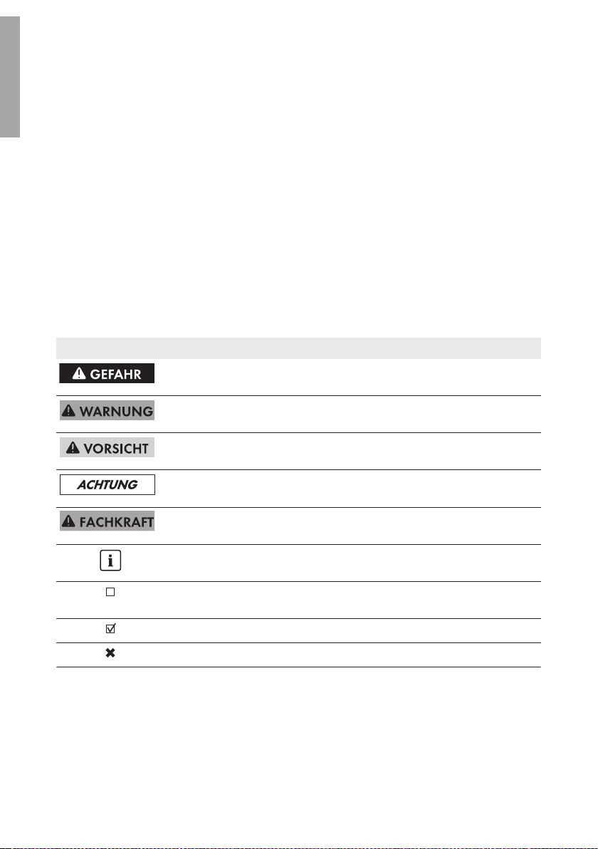
Symbol Erklärung
Warnhinweis, dessen Nichtbeachtung unmittelbar
zum Tod oder zu schwerer Verletzung führt
Warnhinweis, dessen Nichtbeachtung zum Tod
oder zu schwerer Verletzung führen kann
Warnhinweis, dessen Nichtbeachtung zu einer
leichten oder mittleren Verletzung führen kann
Warnhinweis, dessen Nichtbeachtung zu Sachschäden führen kann
Kapitel, in dem Tätigkeiten beschrieben sind, die
nur von Fachkräften durchgeführt werden dürfen
Information, die für ein bestimmtes Thema oder Ziel
wichtig, aber nicht sicherheitsrelevant ist
Voraussetzung, die für ein bestimmtes Ziel gegeben
sein muss
Erwünschtes Ergebnis
Möglicherweise auftretendes Problem
InstallationsanleitungSSMUMast-IA-xx-104
Page 5

SMA Solar Technology AG
2 Bestimmungsgemäße Verwendung
1.4 Nomenklatur
Vollständige Benennung Benennung in diesem Dokument
Mastmontageset für SMA String-Monitore • Produkt
SMA String-Monitor • SMA String-Monitor
• DC-Unterverteiler
2 Bestimmungsgemäße Verwendung
Die Masthalterung ist ein Montagesystem zum Befestigen des SMA String-Monitors an einem Rundoder Vierkantmast.
Die Masthalterung darf nur für folgende Gerätetypen von SMA Solar Technology AG verwendet
werden:
• SMA String-Monitor:
– SSM-U-1610 / SSM-U-1615
– SSM-U-2410 / SSM-U-2415
– SSM-U-3210 / SSM-U-3215
Die Maße des Masts müssen sich für die Masthalterung eignen (siehe Kapitel4 „Montageort
wählen”, Seite6).
Setzen Sie das Produkt ausschließlich nach den Angaben der beigefügten Dokumentationen und
gemäß der vor Ort gültigen Normen und Richtlinien ein. Ein anderer Einsatz kann zu Personenoder Sachschäden führen.
Eingriffe in das Produkt, z. B. Veränderungen und Umbauten, sind nur mit ausdrücklicher
schriftlicher Genehmigung von SMA Solar Technology AG gestattet. Nicht autorisierte Eingriffe
führen zum Wegfall der Garantie- und Gewährleistungsansprüche sowie in der Regel zum
Erlöschen der Betriebserlaubnis. Die Haftung von SMA Solar Technology AG für Schäden aufgrund
solcher Eingriffe ist ausgeschlossen.
Jede andere Verwendung des Produkts als in der bestimmungsgemäßen Verwendung beschrieben
gilt als nicht bestimmungsgemäß.
Die beigefügten Dokumentationen sind Bestandteil des Produkts. Die Dokumentationen müssen
gelesen, beachtet und jederzeit zugänglich aufbewahrt werden.
DEUTSCH
3 Lieferumfang
Prüfen Sie den Lieferumfang auf Vollständigkeit und äußerlich sichtbare Beschädigungen. Setzen
Sie sich bei unvollständigem Lieferumfang oder Beschädigungen mit Ihrem Fachhändler in
Verbindung.
Installationsanleitung 5SSMUMast-IA-xx-10
Page 6

DEUTSCH
4 Montageort wählen
Abbildung 1 : Bestandteile des Lieferumfangs
SMA Solar Technology AG
Position Anzahl Bezeichnung
A 2 C-Profilschiene mit Polyester-Halterung
B 2 Stahlband (Länge: ca. 1.255mm)
C 2 Fixierungsklammer (bestehend aus: 2 Winkeln, 1 Sechskantschrau-
be, 1 Mutter, 1 Unterlegscheibe)
D 4 Kreuzschlitzschraube M6 x 30 mm
E 4 Mutter M6
F 12 Unterlegscheibe M6 (8 Stück werden benötigt, 4 Stück als Ersatz)
4 Montageort wählen
Brandgefahr durch falschen Montageort
Trotz sorgfältiger Konstruktion kann bei elektrischen Geräten ein Brand entstehen.
• Den DC-Unterverteiler nicht auf brennbaren Baustoffen montieren.
• Den DC-Unterverteiler nicht in Bereichen montieren, in denen sich leicht entflammbare Stoffe
befinden.
• Den DC-Unterverteiler nicht in explosionsgefährdeten Bereichen montieren.
Anforderungen an den Montageort:
☐ Der Montageort kann sich im Außenbereich oder im Innenbereich befinden.
☐ Der Montageort darf kein Wohn- oder Büroraum sein.
☐ Durch die Montage darf kein Fluchtweg versperrt sein.
☐ Der Montageort muss jederzeit frei und sicher zugänglich sein, ohne dass zusätzliche
Hilfsmittel (z.B. Gerüste oder Hebebühnen) notwendig sind. Andernfalls sind eventuelle
Service-Einsätze nur eingeschränkt möglich.
☐ Der Montageort muss verschattet sein, z.B. unter einem Schutzdach.
☐ Der Montageort muss sich für Gewicht und Abmessungen des SMA String-Monitors eignen.
☐ Der Montageort muss sich für die Windlast eignen.
☐ Montageraum unter dem SMA String-Monitor bei Verwendung der Sicherungssteckverbinder:
Mindestens 800mm.
InstallationsanleitungSSMUMast-IA-xx-106
Page 7
SMA Solar Technology AG
4 Montageort wählen
Anforderungen an den Mast:
☐ Zulässiger Mastdurchmesser bei Rundmast bzw. Mastbreite bei Vierkantmast:
160 mm … 370mm.
☐ Der Mast muss senkrecht stehen.
☐ Der Mast muss sich für das Gewicht des SMA String-Monitors eignen. Gewicht des SMA
String-Monitors ohne Zubehör: 35 kg.
Anforderungen an die Montage des SMA String-Monitors:
☐ SMA String-Monitor so montieren, dass der Anschlussbereich nach unten zeigt.
☐ SMA String-Monitor waagerecht montieren.
☐ SMA String-Monitor nicht verwindet montieren.
☐ SMA String-Monitor nicht liegend oder geneigt montieren.
☐ Externe Kabelabfangschiene vorsehen.
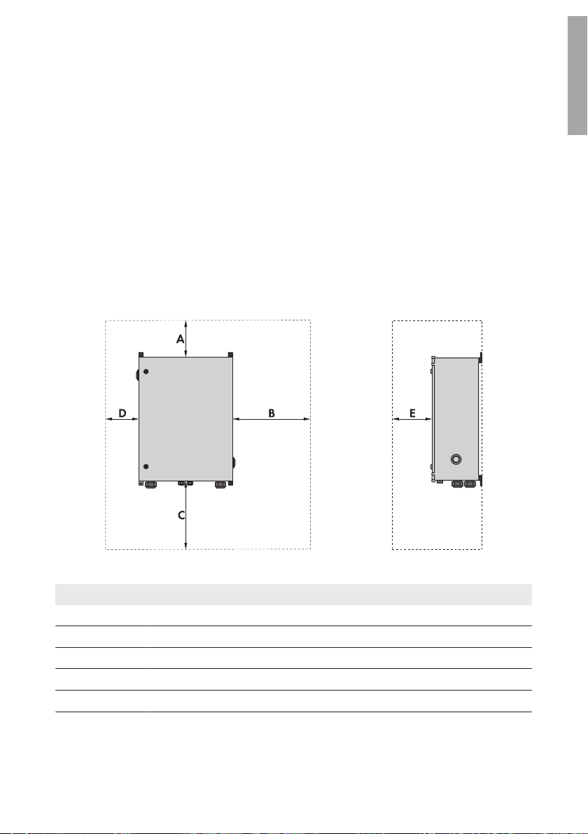
Mindestabstände einhalten:
DEUTSCH
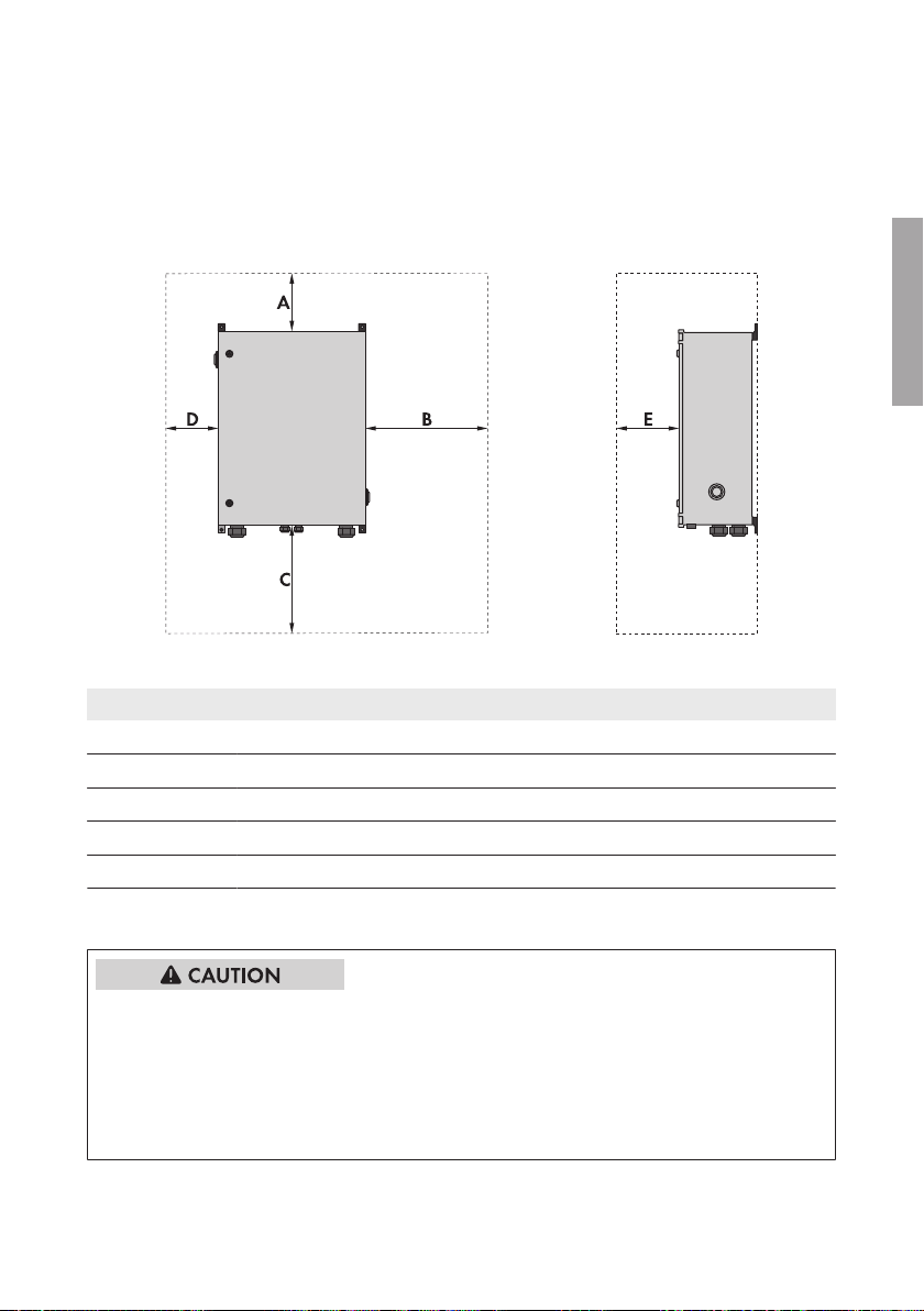
Abbildung 2 : Mindestabstände
Position Erklärung
A 200mm
B 650mm
C 800mm
D 150mm
E 650mm
Installationsanleitung 7SSMUMast-IA-xx-10
Page 8
DEUTSCH
5 SMA String-Monitor am Mast montieren
SMA Solar Technology AG
5 SMA String-Monitor am Mast montieren
Verletzungsgefahr beim Heben und durch Herunterfallen des DC-Unterverteilers
Durch falsches Heben und durch Herunterfallen des DC-Unterverteilers beim Transport oder beim
Auf- und Abhängen besteht Verletzungsgefahr. Gewicht des DC-Unterverteilers ohne eingebautes
Zubehör: 35 kg.
• Für die Montage und Demontage des DC-Unterverteilers 2 Personen vorsehen.
• Den DC-Unterverteiler vorsichtig heben und transportieren.
Vorgehen:
1. Den SMA String-Monitor mit der Vorderseite auf einen sauberen und kratzfesten Untergrund
legen. Dabei darauf achten, dass das Gehäuse des SMA String-Monitors nicht beschädigt
wird.
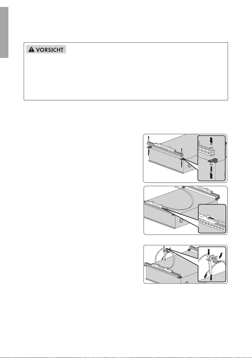
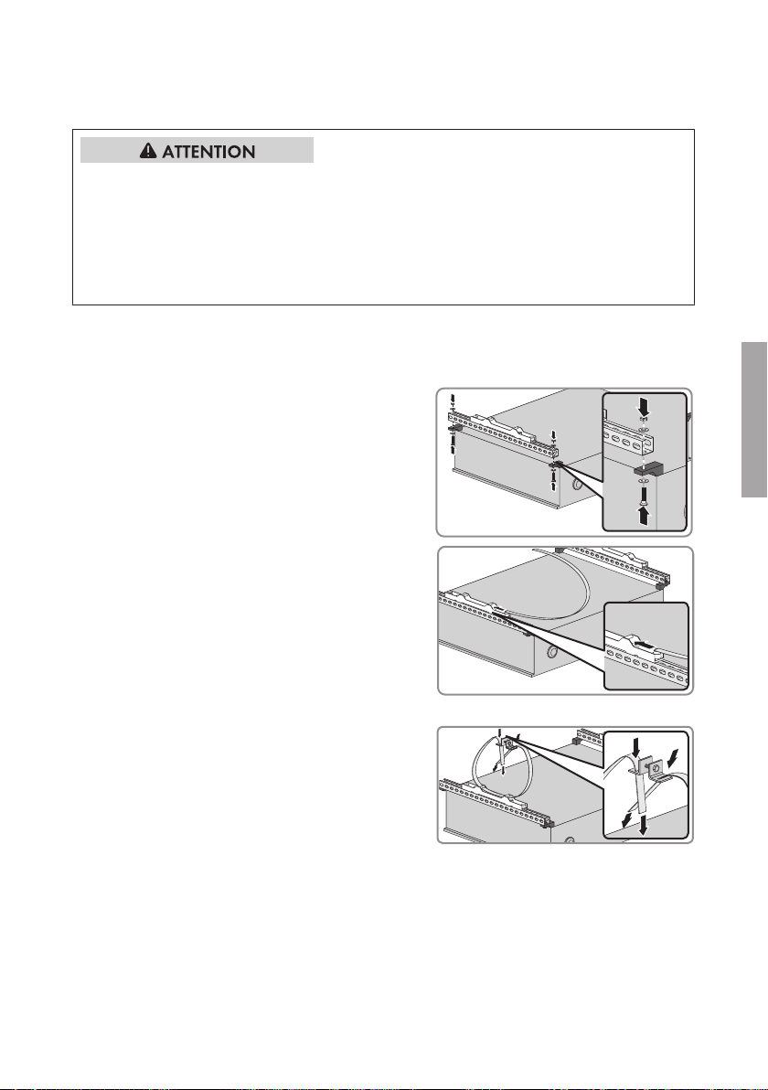
2. C-Profilschienen mit jeweils 1Schraube,
2Unterlegscheiben und 1Mutter an den oberen
und unteren Wandhalterungslaschen des SMA
String-Monitors befestigen.
3. Bei beiden C-Profilschienen jeweils ein
Stahlband durch die Polyester-Halterung ziehen,
bis sich die Polyester-Halterung mittig auf dem
Stahlband befinden.
4. Bei beiden Stahlbändern jeweils folgende Schritte durchführen:
• Die Enden des Stahlbands so weit durch
die Fixierungsklammer ziehen, bis das
Stahlband an die Größe des Masts
angepasst ist.
• Die Enden des Stahlbands umklappen und bei Bedarf kürzen. Dabei mindestens 30mm
an beiden Enden überstehen lassen. Dadurch kann sich das Stahlband nicht aus der
Fixierungsklammer lösen.
InstallationsanleitungSSMUMast-IA-xx-108
Page 9

SMA Solar Technology AG
• Bei beiden Fixierungsklammern die
Verschraubung lösen und für die
Mastmontage bereithalten.
• Den SMA String-Monitor mit der oberen
und unteren Polyester-Halterung an den
Mast drücken und die Enden der
Fixierungsklammern jeweils mit der
Schraube, der Unterlegscheibe und der
Mutter verbinden. Dabei die Schrauben
festziehen, bis der SMA String-Monitor fest
am Mast hängt.
6 SMA String-Monitor vom Mast demontieren
6 SMA String-Monitor vom Mast demontieren
Lebensgefährlicher Stromschlag durch anliegende Spannung
An den spannungsführenden Bauteilen des DC-Unterverteilers liegen hohe Spannungen an. Das
Berühren spannungsführender Bauteile führt zum Tod oder zu schweren Verletzungen durch
Stromschlag.
• Den Wechselrichter DC-seitig freischalten (siehe Anleitung des Wechselrichters).
• Den DC-Unterverteiler freischalten (siehe Anleitung des DC-Unterverteilers).
• Alle im DC-Anschlussbereich des Wechselrichters parallel geschalteten DC-Unterverteiler
freischalten (siehe Anleitung des jeweiligen DC-Unterverteilers).
DEUTSCH
Verletzungsgefahr beim Heben und durch Herunterfallen des DC-Unterverteilers
Durch falsches Heben und durch Herunterfallen des DC-Unterverteilers beim Transport oder beim
Auf- und Abhängen besteht Verletzungsgefahr. Gewicht des DC-Unterverteilers ohne eingebautes
Zubehör: 35 kg.
• Für die Montage und Demontage des DC-Unterverteilers 2 Personen vorsehen.
• Den DC-Unterverteiler vorsichtig heben und transportieren.
Vorgehen:
1. Eine saubere und kratzfeste Unterlage zum Ablegen des SMA String-Monitors bereitlegen.
2. Den SMA String-Monitor außer Betrieb nehmen (siehe Anleitung des SMA String-Monitors).
Installationsanleitung 9SSMUMast-IA-xx-10
Page 10

DEUTSCH
7 Kontakt
3. An beiden Stahlbändern die Schrauben der Fixierungsklammern lösen. Dabei darauf achten,
dass der SMA String-Monitor nicht herunterfällt.
4. An beiden Stahlbändern die Schrauben der Fixierungsklammern entfernen und den SMA
String-Monitor vom Mast nehmen. Dabei den SMA String-Monitor mit der Vorderseite auf die
vorbereitete Unterlage legen.
5. Die Enden der Stahlbänder umklappen und die Fixierungsklammern entfernen.
6. Die Stahlbänder langsam aus den Polyester-Halterungen ziehen.
7. Die Schrauben der C-Profilschienen entfernen und die C-Profilschienen entfernen.
SMA Solar Technology AG
7 Kontakt
Kontaktdaten finden Sie unter www.SMA-Solar.com.
InstallationsanleitungSSMUMast-IA-xx-1010
Page 11

SMA Solar Technology AG
Table of Contents
Table of Contents
1 Information on this Document ................................................. 12
1.1 Validity................................................................................................ 12
1.2 Target Group...................................................................................... 12
1.3 Symbols .............................................................................................. 12
1.4 Nomenclature..................................................................................... 13
2 Intended Use............................................................................. 13
3 Scope of Delivery...................................................................... 13
4 Selecting the Mounting Location ............................................. 14
5 Mounting the SMA String-Monitor on the Pole ...................... 15
6 Removing the SMA String-Monitor from the Pole.................. 17
7 Contact....................................................................................... 17
ENGLISH
Installation Manual 11SSMUMast-IA-xx-10
Page 12
ENGLISH
1 Information on this Document
SMA Solar Technology AG
1 Information on this Document
1.1 Validity
This document is valid for the product type "SSM-U-PM (pole mounting set for SMA StringMonitors).
1.2 Target Group
The activities described in this document must only be performed by qualified persons and/or
instructed persons. Only qualified persons are allowed to perform the activities marked in this
document with a warning symbol and the caption "Qualifiedperson". Qualified persons must have
the following skills:
• Training in how to deal with the dangers and risks associated with installing and using
electrical devices and installations.
• Training in the installation and commissioning of electrical devices and installations
1.3 Symbols
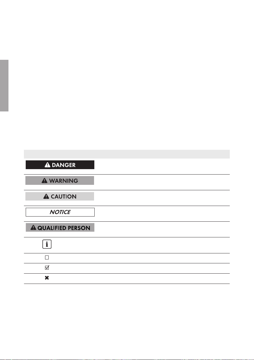
Symbol Explanation
Indicates a hazardous situation which, if not avoided, will result in death or serious injury
Indicates a hazardous situation which, if not avoided, can result in death or serious injury
Indicates a hazardous situation which, if not avoided, can result in minor or moderate injury
Indicates a situation which, if not avoided, can result in property damage
Sections describing activities to be performed by
qualified persons only
Information that is important for a specific topic or
goal, but is not safety-relevant
Indicates a requirement for meeting a specific goal
Desired result
A problem that might occur
Installation ManualSSMUMast-IA-xx-1012
Page 13

SMA Solar Technology AG
1.4 Nomenclature
Complete designation Designation in this document
Pole mounting set for SMA String-Monitors • Product
SMA String-Monitor • SMA String-Monitor
• DC sub-distribution
2 Intended Use
2 Intended Use
Pole mounting is a mounting system used to attach the SMA String-Monitors to a round or square
pole.
Pole mounting must only be used for the following device types from SMA Solar Technology AG:
• SMA String-Monitor:
– SSM-U-1610 / SSM-U-1615
– SSM-U-2410 / SSM-U-2415
– SSM-U-3210 / SSM-U-3215
The dimensions of the pole must be suitable for the pole brackets (see Section4 "Selecting the
Mounting Location", page14).
Use this product only in accordance with the information provided in the enclosed documentation
and with the locally applicable standards and directives. Any other application may cause
personal injury or property damage.
Alterations to the product, e.g. changes or modifications, are only permitted with the express written
permission of SMA Solar Technology AG. Unauthorized alterations will void guarantee and
warranty claims and usually void the operation permit. SMA Solar Technology AG shall not be
held liable for any damage caused by such changes.
Any use of the product other than that described in the Intended Use section does not qualify as
appropriate.
The enclosed documentation is an integral part of this product. Keep the documentation in a
convenient place for future reference and observe all instructions contained therein.
3 Scope of Delivery
Check the scope of delivery for completeness and any externally visible damage. Contact your
distributor if the scope of delivery is incomplete or damaged.
ENGLISH
Figure 3 : Components included in the scope of delivery
Position Quantity Designation
A 2 C profile rail with polyester bracket
Installation Manual 13SSMUMast-IA-xx-10
Page 14

ENGLISH
4 Selecting the Mounting Location
Position Quantity Designation
B 2 Steel wire (length: approx. 1,255mm)
C 2 Fixing bracket (consisting of: 2 brackets, 1 hexagon screw, 1 nut, 1
washer)
D 4 Cross-head screw M6 x 30 mm
E 4 Nut M6
F 12 Washer M6 (8 pcs. are required, 4 pcs. as spare parts)
SMA Solar Technology AG
4 Selecting the Mounting Location
Fire hazard due to wrong choice of mounting location
Despite careful construction, electrical devices can cause fires.
• Do not mount the DC sub-distribution on flammable construction materials.
• Do not mount the DC sub-distribution in areas containing highly flammable materials.
• Do not mount the DC sub-distribution in potentially explosive atmospheres.
Requirements for the mounting location:
☐ The mounting location can be outdoors or indoors.
☐ The mounting location must not be in a living or office area.
☐ The mounting location must not block any escape routes.
☐ The mounting location must be freely and safely accessible at all times without the necessity for
any auxiliary equipment (e.g. scaffolding or lifting platforms). Non-fulfillment of these criteria
may restrict servicing.
☐ The mounting location must be shaded, e.g. under a protective roof.
☐ The mounting location must be suitable for the weight and dimensions of the SMA
SunnyString‑Monitor.
☐ The mounting location must be suitable for the wind load.
☐ Mounting space below the SMAStringMonitor when using the inline fuse connectors:
at least 800mm.
Pole requirements:
☐ Permissible pole diameter for round pole respectively pole width for square pole:
160mm to 370mm
☐ The pole must be in a vertical position.
☐ The pole must be suitable for the weight of the SMA StringMonitor. Weight of the
SMAString-Monitor without accessories: 35 kg.
Requirements for mounting the SMAString-Monitor
☐ Mount the SMASunnyString-Monitor so that the connection area is facing downwards.
Installation ManualSSMUMast-IA-xx-1014
Page 15
SMA Solar Technology AG
5 Mounting the SMA String-Monitor on the Pole
☐ Mount the SMAString-Monitor in a horizontal position.
☐ Do not mount the SMAString Monitor in a twisted manner.
☐ Do not mount the SMASunnyString‑Monitor in a horizontal or inclined position.
☐ An external cable support rail must be provided.
Observe minimum clearances:
Figure 4 : Minimum clearances
ENGLISH
Position Explanation
A 200mm
B 650mm
C 800mm
D 150mm
E 650mm
5 Mounting the SMA String-Monitor on the Pole
Risk of injury when lifting the DC sub-distribution, or if it is dropped
There is risk of injury if the DC sub-distribution is lifted incorrectly or dropped while being
transported or when attaching it to or removing it from the wall mounting bracket. Weight of the
DC sub-distribution without installed accessories: 35 kg.
• Two persons are required for mounting and disassembling the DC sub-distribution.
• Carefully lift and transport the DC sub-distribution.
Installation Manual 15SSMUMast-IA-xx-10
Page 16

ENGLISH
5 Mounting the SMA String-Monitor on the Pole
SMA Solar Technology AG
Procedure:
1. Position the SMAString-Monitor with the front on a clean and scratch-proof support surface.
Make sure that the enclosure of the SMAString-Monitor is not damaged.
2. Attach the C profile rails to the upper and lower
wall mounting brackets of the SMAStringMonitor using one screw, two washers and one
nut for each rail.
3. Lead a steel wire through the polyester bracket
of each of the C profile rails until the polyester
bracket is in the middle of the steel wire.
4. Perform the following steps for both steel wires:
• Pull the ends of the steel wire through the
fixing bracket until the steel wire is adjusted
to the dimensions of the pole.
• Fold the ends of the steel wire back and shorten if required. At least 30mm on both ends
must protrude. The steel wire is thus firmly positioned in the fixing bracket.
• Remove both fixing brackets from the screw
connection and place them in readiness for
pole mounting.
• Push the SMAString-Monitor with the upper
and lower polyester bracket against the
pole and connect the ends of the fixing
brackets with the screw, the washer and the
nut. Tighten the screws until the SMAStringMonitor is firmly attached to the pole.
Installation ManualSSMUMast-IA-xx-1016
Page 17
SMA Solar Technology AG
6 Removing the SMA String-Monitor from the Pole
6 Removing the SMA String-Monitor from the Pole
Danger to life from electric shock due to live voltage
High voltages are present in the live components of the DC sub-distribution. Touching live
components results in death or serious injury due to electric shock.
• Disconnect the inverter on the DC side (see the inverter manual).
• Disconnect the DC sub-distribution (see the DC sub-distribution manual).
• Disconnect all DC sub-distributions that are connected in parallel in the DC connection area
(see the manual of the respective DC sub-distribution).
Risk of injury when lifting the DC sub-distribution, or if it is dropped
There is risk of injury if the DC sub-distribution is lifted incorrectly or dropped while being
transported or when attaching it to or removing it from the wall mounting bracket. Weight of the
DC sub-distribution without installed accessories: 35 kg.
• Two persons are required for mounting and disassembling the DC sub-distribution.
• Carefully lift and transport the DC sub-distribution.
Procedure:
1. A clean and scratch-proof surface for the SMAString-Monitor must be provided.
2. Decommission the SMAString-Monitor (see the SMA StringMonitor manual).
3. Loosen the screws of the fixing brackets on both steel wires. Make sure that the SMAStringMonitor does not fall down.
4. Remove the screws of the fixing brackets on both steel wires and take the SMAString-Monitor
off the pole. Position the SMAString-Monitor with the front on the prepared surface.
5. Fold back the ends of the steel wires and remove the fixing brackets.
6. Slowly pull out the steel wires from the polyester brackets.
7. Remove the screws from the C profile rails and then remove the C profile rails.
ENGLISH
7 Contact
You can find the contact data at www.SMA-Solar.com.
Installation Manual 17SSMUMast-IA-xx-10
Page 18

Table des matières
SMA Solar Technology AG
Table des matières
1 Remarques relatives à ce document....................................... 19
1.1 Champ d’application......................................................................... 19
1.2 Groupe cible ...................................................................................... 19
1.3 Symboles ............................................................................................ 19
1.4 Nomenclature..................................................................................... 20
2 Utilisation conforme.................................................................. 20
3 Contenu de la livraison ............................................................ 20
FRANÇAIS
4 Choix du lieu de montage........................................................ 21
5 Montage du SMA String‑Monitor au mât............................... 23
6 Démontage de SMA String‑Monitor du mât........................... 24
7 Contact....................................................................................... 25
Instructions d’installationSSMUMast-IA-xx-1018
Page 19
SMA Solar Technology AG
1 Remarques relatives à ce document
1 Remarques relatives à ce document
1.1 Champ d’application
Ce document est valide pour le type de produit «SSM-U-PM» (jeu de montage sur mât pour le
SMAString-Monitor).
1.2 Groupe cible
Les opérations décrites dans le présent document doivent uniquement être réalisées par du
personnel qualifié ou des personnes averties. Les opérations identifiées dans le présent document
par un symbole d’avertissement et par le mot «Personnel qualifié» ne doivent être réalisées que
par du personnel qualifié. Le personnel qualifié doit posséder les qualifications suivantes:
• Formation au comportement à adopter face aux dangers et risques encourus lors de
l’installation et de la manipulation d’appareils et installations électriques
• Formation à l’installation et à la mise en service des appareils et installations électriques
1.3 Symboles
Symbole Explication
Consigne de sécurité dont le non-respect entraîne
inévitablement des blessures corporelles graves voire mortelles
Consigne de sécurité dont le non-respect peut entraîner des blessures corporelles graves voire mortelles
Consigne de sécurité dont le non-respect peut entraîner des blessures corporelles légères ou de moyenne gravité
Consigne de sécurité dont le non-respect peut entraîner des dommages matériels
Chapitre décrivant des opérations qui ne doivent
être réalisées que par du personnel qualifié
Information importante sur un thème ou un objectif
précis, mais ne relevant pas de la sécurité
Condition devant être remplie pour atteindre un objectif précis
Résultat souhaité
Problème susceptible de survenir
FRANÇAIS
Instructions d’installation 19SSMUMast-IA-xx-10
Page 20

FRANÇAIS
2 Utilisation conforme
SMA Solar Technology AG
1.4 Nomenclature
Désignation complète Désignation dans ce document
Jeu de montage sur mât pour le SMAString-Monitor
SMAString-Monitor • SMAString-Monitor
• Produit
• Sous-distributeur DC
2 Utilisation conforme
Le jeu de montage sur mât est un système de montage pour la fixation du SMAString-Monitor à un
poteau rond ou rectangulaire.
Le jeu de montage sur mât ne doit être utilisé que pour les types d’appareils suivants de SMA Solar
Technology AG:
• SMAString-Monitor:
– SSM-U-1610 / SSM-U-1615
– SSM-U-2410 / SSM-U-2415
– SSM-U-3210 / SSM-U-3215
Les dimensions du mât doivent être adaptées au jeu de montage (voir chapitre4 «Choix du lieu
de montage», page21).
Utilisez ce produit exclusivement en conformité avec la documentation fournie ainsi qu’avec les
normes et directives en vigueur sur le site. Tout autre usage peut compromettre la sécurité des
personnes ou entraîner des dommages matériels.
Les interventions sur le produit (modifications ou transformations, par exemple) ne sont autorisées
qu’après accord écrit de SMA Solar Technology AG. Toute intervention non autorisée entraîne
l’annulation de la garantie légale et commerciale et en règle générale le retrait de l’autorisation
d’exploitation. SMA Solar Technology AG décline toute responsabilité en cas de dommages
résultant d’une telle intervention.
Toute utilisation du produit différente de celle décrite dans l’utilisation conforme est considérée
comme non conforme.
Les documents joints font partie intégrante du produit. Les documents doivent être lus, respectés et
rester accessibles à tout moment.
3 Contenu de la livraison
Vérifiez si la livraison est complète et ne présente pas de dommages apparents. En cas de livraison
incomplète ou de dommages, contactez votre revendeur.
Instructions d’installationSSMUMast-IA-xx-1020
Page 21
SMA Solar Technology AG
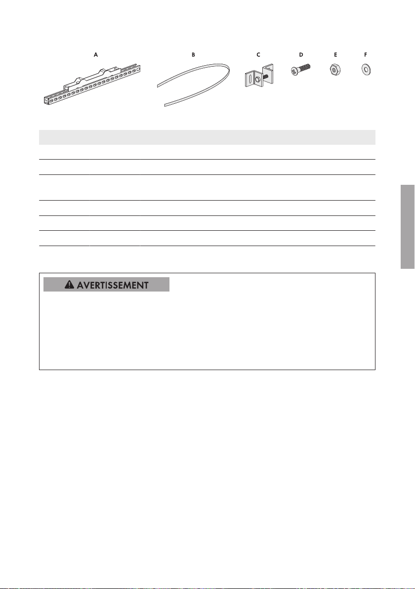
Figure 5 : Éléments du contenu de livraison
4 Choix du lieu de montage
Position Quantité Désignation
A 2 Profilé C avec fixation en polyester
B 2 Bande en acier (longueur: 1255mm)
C 2 Attache (y compris: 2équerres, 1vis à six pans, 1écrou, 1rondel-
le)
D 4 Vis à tête cruciforme M6 x 30mm
E 4 Écrou M6
F 12 Rondelle M6 (8pièces sont nécessaires, 4pièces de rechange)
4 Choix du lieu de montage
Risque d’incendie en cas de mauvais lieu de montage
En dépit d’un assemblage réalisé avec le plus grand soin, tout appareil électrique peut présenter
un risque d’incendie.
• Ne montez pas le sous-distributeurDC sur des matériaux inflammables.
• Ne montez pas le sous-distributeurDC à proximité de matériaux facilement inflammables.
• Ne montez pas le sous-distributeurDC dans des zones présentant un danger d’explosion.
FRANÇAIS
Exigences relatives au lieu de montage:
☐ Le lieu de montage peut se situer à l’intérieur ainsi qu’à l’extérieur.
☐ Le lieu de montage ne doit pas se trouver dans une pièce d’habitation ou un bureau.
☐ Aucune issue de secours ne doit être bloquée en raison du montage.
☐ Le lieu de montage doit toujours être sécurisé et accessible facilement, sans qu’il soit
nécessaire de recourir à un équipement supplémentaire (par exemple à des échafaudages ou
à des plates-formes élévatrices). Dans le cas contraire, les interventions SAV ne pourront être
effectuées que de manière restreinte.
☐ Le lieu de montage doit être ombragé, par exemple, à l’abri d’un toit protecteur.
☐ Le lieu de montage doit être adapté au poids et aux dimensions du SMAString‑Monitor.
☐ Le lieu de montage doit être adapté à la charge de vent.
☐ Local de montage sous le SMAString-Monitor en cas de l’utilisation du connecteur porte-
fusible:
au moins 800mm.
Instructions d’installation 21SSMUMast-IA-xx-10
Page 22

FRANÇAIS
4 Choix du lieu de montage
SMA Solar Technology AG
Exigences relatives au mât:
☐ Diamètre admissible du mât en cas de poteau rond ou largeur du mât en cas de poteau
rectangulaire:
160mm à 370mm.
☐ Le mât doit être installé à la verticale.
☐ Le mât doit être adapté au poids du SMAString‑Monitor. Poids du SMAString-Monitor sans
accessoires: 35 kg
Exigences relatives au montage du SMAString-Monitor:
☐ Montez le SMAString‑Monitor de façon à ce que la zone de raccordement soit orientée vers
le bas.
☐ Montez le SMAString‑Monitor horizontalement.
☐ Ne montez pas le SMAString‑Monitor de manière tordu.
☐ Ne montez pas le SMAString‑Monitor de manière couchée ou inclinée.
☐ Prévoyez un rail externe de fixation des câbles.
Respecter les distances minimales:
Figure 6 : Distances minimales
Position Explication
A 200mm
B 650mm
C 800mm
D 150mm
E 650mm
Instructions d’installationSSMUMast-IA-xx-1022
Page 23
SMA Solar Technology AG
5 Montage du SMA String‑Monitor au mât
5 Montage du SMA String‑Monitor au mât
Risque de blessure dû à la chute du sous-distributeur DC lors de son soulèvement
Il existe un risque de blessure en cas de soulèvement incorrect et de chute du sous-distributeur DC
lors du transport ainsi que lors de l’accrochage ou du décrochage. Poids du sous-distributeur DC
sans accessoires intégrés: 35 kg
• Prévoyez deux personnes pour le montage et démontage du sous-distributeur DC.
• Le sous-distributeurDC doit être transporté et levé avec précaution.
Procédure:
1. Posez le SMAString-Monitor avec le panneau avant sur une surface propre et résistant aux
éraflures. Veillez à ne pas endommager le boîtier du SMAString-Monitor.
2. Fixez chaque profilé C avec une vis, deux
rondelles et un écrou au support mural supérieur
et inférieur du SMAString-Monitor.
3. Tirez une bande en acier par la fixation en
polyester de chaque profilé C jusqu’à la fixation
en polyester se trouve au centre de la bande en
acier.
FRANÇAIS
4. Pour les deux bandes en acier, effectuez les opérations suivantes:
• Tirez les extrémités de la bande en acier
par les attaches jusqu’à la bande est
adaptée aux dimensions du mât.
• Rabattez les extrémités de la bande en acier et raccourcissez-les si nécessaire. Veillez à
ce qu’au moins 30mm dépassent sur les deux côtés. Ainsi, la bande en acier ne peut pas
se détacher de l’attache.
Instructions d’installation 23SSMUMast-IA-xx-10
Page 24

FRANÇAIS
6 Démontage de SMA String‑Monitor du mât
• Détachez les deux attaches du raccord à
vis et gardez-les à disposition pour le
montage au mât.
• Poussez le SMAString-Monitor au mât
avec la fixation en polyester supérieure et
inférieure et connectez chaque extrémité de
l’attache avec une vis, une rondelle et un
écrou. Resserrez les vis jusqu’à le
SMAString-Monitor est fixé au mât.
SMA Solar Technology AG
6 Démontage de SMA String‑Monitor du mât
Danger de mort par choc électrique dû à une tension
Les composants conducteurs du sous-distributeur DC sont soumis à de hautes tensions. Le contact
avec des composants conducteurs entraîne des blessures graves, voire la mort par choc
électrique.
• Mettez hors tension l’onduleur côté DC (voir les instructions de l’onduleur).
• Mettez hors tension le sous-distributeurDC (voir les instructions du sous-distributeurDC).
• Mettez hors tension tous les sous-distributeursDC raccordés en parallèle dans la zone de
raccordement DC dans l’onduleur (voir les instructions du sous-distributeurDC).
Risque de blessure dû à la chute du sous-distributeur DC lors de son soulèvement
Il existe un risque de blessure en cas de soulèvement incorrect et de chute du sous-distributeur DC
lors du transport ainsi que lors de l’accrochage ou du décrochage. Poids du sous-distributeur DC
sans accessoires intégrés: 35 kg
• Prévoyez deux personnes pour le montage et démontage du sous-distributeur DC.
• Le sous-distributeurDC doit être transporté et levé avec précaution.
Procédure:
1. Veillez à ce que la surface pour poser le SMAString-Monitor est propre et résistant aux
éraflures.
2. Mettez hors service le SMAString-Monitor (voir instructions du SMAString-Monitor).
Instructions d’installationSSMUMast-IA-xx-1024
Page 25

SMA Solar Technology AG
3. Dévissez les vis des attaches pour les deux bandes en acier. Veillez à ce que le SMAStringMonitor ne tombe pas.
4. Retirez les vis des attaches pour les deux bandes en acier et enlevez le SMAString-Monitor
du mât. Posez le SMAString-Monitor avec la face avant sur la surface préparée.
5. Rabattez les extrémités des bandes en acier et retirez les attaches.
6. Tirez les bandes en acier lentement des fixations en polyester.
7. Dévissez les vis des profilés C et retirez les profilés C.
7 Contact
7 Contact
Vous trouverez les coordonnées sur www.SMA-Solar.com.
FRANÇAIS
Instructions d’installation 25SSMUMast-IA-xx-10
Page 26

ESPAÑOL
Índice
SMA Solar Technology AG
Índice
1 Indicaciones sobre este documento........................................ 27
1.1 Área de validez.................................................................................. 27
1.2 Grupo de destinatarios...................................................................... 27
1.3 Símbolos ............................................................................................. 27
1.4 Nomenclatura .................................................................................... 28
2 Uso previsto .............................................................................. 28
3 Contenido de la entrega .......................................................... 28
4 Elección del lugar de montaje ................................................. 29
5 Montaje del SMA String-Monitor en el poste......................... 31
6 Desmontaje del poste del SMA String-Monitor...................... 32
7 Contacto .................................................................................... 33
Instrucciones de instalaciónSSMUMast-IA-xx-1026
Page 27

SMA Solar Technology AG
1 Indicaciones sobre este documento
1 Indicaciones sobre este documento
1.1 Área de validez
Este documento es válido para el tipo de producto “SSM-U-PM” (juego de montaje en poste para
SMAString-Monitor).
1.2 Grupo de destinatarios
Las actividades descritas en este documento deben realizarlas exclusivamente especialistas o
personas instruidas. Las tareas marcadas en este documento con un símbolo de advertencia y la
palabra “Especialista” deben llevarlas a cabo únicamente especialistas. Los especialistas han de
contar con esta cualificación:
• Formación sobre cómo actuar ante los peligros y riesgos relativos a la instalación y el manejo
de equipos eléctricos y plantas
• Formación profesional para la instalación y la puesta en marcha de equipos eléctricos y
plantas
1.3 Símbolos
Símbolo Explicación
Advertencia que, de no ser observada, causa la
muerte o lesiones físicas graves
Advertencia que, de no ser observada, puede
causar la muerte o lesiones físicas graves
Advertencia que, de no ser observada, puede
causar lesiones físicas leves o de gravedad media
Advertencia que, de no ser observada, puede
causar daños materiales
Capítulos en los que se describen tareas que deben ser llevadas a cabo únicamente por especialistas
Información importante para un tema u objetivo
concretos, aunque no relevante para la seguridad
Requisito necesario para alcanzar un objetivo determinado
Resultado deseado
Posible problema
ESPAÑOL
Instrucciones de instalación 27SSMUMast-IA-xx-10
Page 28

ESPAÑOL
2 Uso previsto
SMA Solar Technology AG
1.4 Nomenclatura
Denominación completa Denominación utilizada en este documento
Juego de montaje en poste para SMAStringMonitor
SMAString-Monitor • SMAString-Monitor
• Producto
• Subdistribuidor de CC
2 Uso previsto
El soporte para postes es un sistema de montaje para fijar el SMAString-Monitor a un poste
cilíndrico o cuadrado.
El soporte para postes debe utilizarse únicamente para estos modelos de SMA Solar Technology
AG:
• SMAString-Monitor:
– SSM-U-1610/SSM-U-1615
– SSM-U-2410/SSM-U-2415
– SSM-U-3210/SSM-U-3215
El poste debe tener las dimensiones adecuadas para el soporte para postes (consulte el capítulo4
“Elección del lugar de montaje”, página29).
Utilice siempre el producto de acuerdo con las indicaciones de la documentación adjunta y
observe las normativas y directivas locales vigentes. Cualquier otro uso puede causarle lesiones al
usuario o daños materiales.
Para realizar cualquier intervención en el producto, como modificaciones o remodelaciones,
deberá contar con el permiso expreso y por escrito de SMA Solar Technology AG. Los cambios no
autorizados pueden conducir a la pérdida de los derechos de garantía así como a la extinción del
permiso de explotación. Queda excluida la responsabilidad de SMA Solar Technology AG por los
daños derivados de dichos cambios.
Cualquier uso del producto distinto al descrito en el uso previsto se considerará uso inadecuado.
La documentación adjunta es parte integrante del producto. La documentación debe leerse,
observarse y conservarse en un lugar accesible en todo momento.
3 Contenido de la entrega
Compruebe que el contenido de la entrega esté completo y que no presente daños externos
visibles. En caso de que no esté completo o presente daños, póngase en contacto con su
distribuidor.
Instrucciones de instalaciónSSMUMast-IA-xx-1028
Page 29

SMA Solar Technology AG
Imagen 7 : Contenido de la entrega
4 Elección del lugar de montaje
Posición Cantidad Denominación
A 2 Carril de montaje tipo C con soporte de poliéster
B 2 Fleje de acero (longitud: aprox. 1255mm)
C 2 Tensor (compuesto por: 2piezas angulares, 1tornillo hexagonal,
1tuerca, 1arandela)
D 4 Tornillo con cabeza en cruz M6 x 30mm
E 4 Tuerca M6
F 12 Arandela M6 (se necesitan ocho, cuatro son de repuesto)
4 Elección del lugar de montaje
Peligro de incendio debido a un lugar de montaje inadecuado
A pesar de estar cuidadosamente construidos, los equipos eléctricos pueden originar incendios.
• No monte el subdistribuidor de CC sobre materiales inflamables.
• No monte el subdistribuidor de CC en áreas en las que se encuentren materiales fácilmente
inflamables.
• No monte el subdistribuidor de CC en áreas con peligro de explosión.
ESPAÑOL
Requisitos del lugar de montaje:
☐ El lugar de montaje puede ser en exteriores e interiores.
☐ El lugar de montaje no debe ser ninguna vivienda u oficina.
☐ Con el montaje no debe bloquearse ninguna vía de emergencia.
☐ El lugar de montaje debe ser accesible de forma fácil y segura, sin necesidad de medios
auxiliares adicionales como, p.ej., andamios o plataformas elevadoras. De lo contrario, los
trabajos técnicos solo serán posibles de manera limitada.
☐ El lugar de montaje debe estar a la sombra, p.ej. debajo de un techo protector.
☐ El lugar de montaje debe ser adecuado para el peso y las dimensiones del
SMAString‑Monitor .
☐ El lugar de montaje debe ser adecuado para la carga del viento.
☐ Espacio de montaje debajo del SMAString-Monitor si se usan conectores de seguridad:
Mínimo 800mm.
Instrucciones de instalación 29SSMUMast-IA-xx-10
Page 30

ESPAÑOL
4 Elección del lugar de montaje
SMA Solar Technology AG
Requisitos para el poste:
☐ Diámetro (para poste cilíndrico) o ancho (para poste cuadrado) permitido:
160mm … 370mm.
☐ El poste debe estar en posición vertical.
☐ El poste debe ser adecuado para el peso y las dimensiones del SMAString‑Monitor. Peso del
SMAString-Monitor sin accesorios: 35 kg.
Requisitos para el montaje del SMAString-Monitor
☐ Monte el SMAString-Monitor de modo que el área de conexión esté orientada hacia abajo.
☐ Monte el SMAString-Monitor en horizontal.
☐ No monte el SMAString-Monitor torcido.
☐ No monte el SunnyString-Monitor tumbado o inclinado.
☐ Prevea un riel externo para el paso de los cables.
Respete las distancias mínimas:
Imagen 8 : Distancias mínimas
Posición Explicación
A 200mm
B 650mm
C 800mm
D 150mm
E 650mm
Instrucciones de instalaciónSSMUMast-IA-xx-1030
Page 31

SMA Solar Technology AG
5 Montaje del SMA String-Monitor en el poste
5 Montaje del SMA String-Monitor en el poste
Peligro de lesiones al levantar o caerse el subdistribuidor de CC
Existe peligro de lesiones por levantar el subdistribuidor de CC de forma inadecuada y si se cae
durante el transporte o al colgarlo y descolgarlo. Peso del subdistribuidor de CC sin accesorios
integrados: 35 kg.
• Para montar y desmontar el subdistribuidor de CC son necesarias dos personas.
• Levante y transporte el subdistribuidor de CC con cuidado.
Procedimiento:
1. Coloque el SMAString-Monitor con su lado frontal sobre una superficie limpia y resistente a
arañazos. Preste atención a no dañar la carcasa del SMAString-Monitor.
2. Fije los carriles de montaje tipo C cada uno con
un tornillo, dos arandelas y una tuerca a las
placas de soporte mural superiores e inferiores
del SMAString-Monitor.
3. Pase en cada carril de montaje un fleje de acero
por el soporte de poliéster hasta que esté
centrado.
ESPAÑOL
4. Siga estos pasos para ambos flejes de acero:
• Pase los extremos del fleje de acero por el
tensor hasta que se ajuste al tamaño del
poste.
• Pliegue los extremos del fleje y, en caso necesario, acórtelos. Deje sobresalir al menos
30mm en ambos extremos. De esta manera, el fleje no se soltará del tensor.
Instrucciones de instalación 31SSMUMast-IA-xx-10
Page 32

6 Desmontaje del poste del SMA String-Monitor
• Retire el tornillo de ambos tensores y
manténgalos a disposición para el montaje
en el poste.
• Apoye el SMAString-Monitor en el poste
con el soporte de poliéster superior e
inferior y junte los extremos de los tensores
con el tornillo, la arandela y la tuerca.
Ajuste los tornillos hasta que el SMAStringMonitor esté sujetado firmemente en el
poste.
SMA Solar Technology AG
6 Desmontaje del poste del SMA String-Monitor
ESPAÑOL
Peligro de muerte por descarga eléctrica debido a la tensión
En los componentes conductores del subdistribuidor de CC existen altas tensiones. Tocar
componentes conductores de tensión puede causar la muerte o lesiones graves por descargas
eléctricas.
• Desconecte el inversor del lado de CC (consulte las instrucciones del inversor).
• Desconecte el subdistribuidor de CC (consulte las instrucciones del subdistribuidor de CC).
• Desconecte todos los subdistribuidores de CC conectados en paralelo en el área de
conexión de CC del inversor (consulte las instrucciones del subdistribuidor de CC).
Peligro de lesiones al levantar o caerse el subdistribuidor de CC
Existe peligro de lesiones por levantar el subdistribuidor de CC de forma inadecuada y si se cae
durante el transporte o al colgarlo y descolgarlo. Peso del subdistribuidor de CC sin accesorios
integrados: 35 kg.
• Para montar y desmontar el subdistribuidor de CC son necesarias dos personas.
• Levante y transporte el subdistribuidor de CC con cuidado.
Procedimiento:
1. Prepare una superficie limpia y resistente a arañazos para apoyar el SMAString-Monitor.
2. Ponga el SMAString-Monitor fuera de servicio (consulte las instrucciones del SMAStringMonitor).
Instrucciones de instalaciónSSMUMast-IA-xx-1032
Page 33

SMA Solar Technology AG
3. Afloje los tornillos de los tensores en ambos flejes de acero. Tenga cuidado que no se caiga
el SMAString-Monitor.
4. Retire los tornillos de los tensores en ambos flejes de acero y retire el SMAString-Monitor del
poste. Coloque el SMAString-Monitor con su lado frontal sobre la superficie preparada.
5. Despliegue los extremos de los flejes de acero y retire los tensores.
6. Retire con cuidado los flejes de acero de los soportes de poliéster.
7. Retire los carriles de montaje aflojando sus tornillos.
7 Contacto
7 Contacto
Encontrará la información de contacto en www.SMA-Solar.com.
Instrucciones de instalación 33SSMUMast-IA-xx-10
ESPAÑOL
Page 34

Índice
SMA Solar Technology AG
Índice
1 Observações relativas a este documento .............................. 35
1.1 Aplicabilidade.................................................................................... 35
1.2 Grupo-alvo ......................................................................................... 35
1.3 Símbolos ............................................................................................. 35
1.4 Nomenclatura .................................................................................... 36
2 Utilização prevista.................................................................... 36
3 Material fornecido.................................................................... 36
4 Seleccionar o local de montagem........................................... 37
5 Montar o SMA String-Monitor no poste ................................. 39
6 Desmontar o SMA String-Monitor do poste ........................... 40
7 Contactos................................................................................... 41
PORTUGUÊS
Manual de instalaçãoSSMUMast-IA-xx-1034
Page 35

SMA Solar Technology AG
1 Observações relativas a este documento
1 Observações relativas a este documento
1.1 Aplicabilidade
Este documento aplica-se ao tipo de produto "SSM-U-PM" (conjunto de montagem em poste para
SMAString-Monitor).
1.2 Grupo-alvo
As actividades descritas neste documento só podem ser executadas por técnicos especializados e/
ou pessoas devidamente formadas. As actividades que neste documento estão assinaladas com
um símbolo de aviso e a designação “Técnico especializado” devem ser executadas
exclusivamente por técnicos especializados. Os técnicos especializados devem ter as seguintes
qualificações:
• Formação sobre perigos e riscos na instalação e operação de aparelhos e sistemas eléctricos
• Formação sobre a instalação e colocação em serviço de aparelhos e sistemas eléctricos
1.3 Símbolos
Símbolo Explicação
Aviso que, se não observado, será imediatamente
fatal ou causará uma lesão grave
Aviso que, se não observado, poderá ser fatal ou
causar uma lesão grave.
Aviso que, se não observado, poderá causar uma
lesão leve ou moderada
Aviso que, se não observado, poderá causar danos materiais
Capítulo em que são descritas actividades que
apenas podem ser executadas por técnicos especializados
Informação importante para um determinado tema
ou objectivo, sem ser relevante para a segurança
Pré-requisito que é necessário estar cumprido para
se alcançar um determinado objectivo
Resultado pretendido
Problema eventualmente ocorrido
PORTUGUÊS
Manual de instalação 35SSMUMast-IA-xx-10
Page 36

2 Utilização prevista
1.4 Nomenclatura
2 Utilização prevista
O suporte para poste é um sistema de montagem para fixar o SMAString-Monitor a um poste de
secção circular ou quadrangular.
O suporte para poste só pode ser utilizado para os seguintes modelos de aparelho da SMA Solar
Technology AG:
As dimensões do poste tem de ser adequadas ao suporte para poste (ver capítulo4 "Seleccionar
o local de montagem", página37).
Utilizar o produto exclusivamente de acordo com as indicações da documentação em anexo e as
normas e directivas em vigor no local de instalação. Qualquer outra utilização pode resultar em
danos físicos ou materiais.
Intervenções no produto, p.ex., modificações e conversões, só são permitidas se tal for
expressamente autorizado, por escrito, pela SMA Solar Technology AG. Intervenções não
autorizadas têm como consequência a cessação dos direitos relativos à garantia, bem como, em
regra, a anulação da licença de operação. A SMA Solar Technology AG não assume qualquer
PORTUGUÊS
responsabilidade por danos resultantes de tais intervenções.
Qualquer outra utilização do produto, que não se encontre descrita como utilização prevista, é
considerada como desadequada e indevida.
Os documentos fornecidos são parte integrante do produto. Os documentos têm de ser lidos,
respeitados e guardados sempre em local acessível.
SMA Solar Technology AG
Designação completa Designação neste documento
Conjunto de montagem em poste para
SMAString-Monitor
SMAString-Monitor • SMAString-Monitor
• SMAString-Monitor:
– SSM-U-1610 / SSM-U-1615
– SSM-U-2410 / SSM-U-2415
– SSM-U-3210 / SSM-U-3215
• Produto
• SubdistribuidorCC
3 Material fornecido
Verifique se o material fornecido está completo e se apresenta danos exteriores visíveis. Se o
material fornecido estiver incompleto ou danificado, contacte o seu vendedor especializado.
Manual de instalaçãoSSMUMast-IA-xx-1036
Page 37

SMA Solar Technology AG
Figura 9 : Material fornecido
4 Seleccionar o local de montagem
Posição Quantidade Designação
A 2 Calha de perfil em C com suporte de poliéster
B 2 Cinta de aço (comprimento: aprox. 1255mm)
C 2 Grampo de fixação (constituído por: 2ângulos, 1parafuso de ca-
beça sextavada, 1porca, 1anilha plana)
D 4 Parafuso Phillips M6 x 30mm
E 4 Porca M6
F 12 Anilha plana M6 (8necessárias, 4sobresselentes)
4 Seleccionar o local de montagem
Perigo de incêndio devido a local de montagem errado
Apesar de uma construção cuidadosa, os aparelhos eléctricos podem incendiar-se.
• Não montar o subdistribuidorCC sobre materiais de construção inflamáveis.
• Não montar o subdistribuidorCC em zonas onde se encontrem materiais facilmente
inflamáveis.
• Não montar o subdistribuidorCC em zonas onde exista perigo de explosão.
Requisitos aplicáveis ao local de montagem:
☐ O local de montagem tanto pode ser no exterior como no interior.
☐ O local de montagem não pode ser habitação ou escritório.
☐ A montagem não pode bloquear caminhos de evacuação.
☐ Deve ser sempre possível aceder ao local de montagem, de forma fácil e segura, sem recorrer
a equipamentos auxiliares (p.ex., andaimes ou plataformas elevatórias). Caso contrário,
eventuais intervenções da assistência apenas serão possíveis de forma limitada.
☐ O local de montagem tem de estar à sombra (p.ex., sob um alpendre).
☐ O local de montagem tem de ser adequado ao peso e às dimensões do SMAString‑Monitor.
☐ O local de montagem tem de ser adequado à carga de vento.
☐ Espaço de montagem sob o SMAString-Monitor em caso de utilização dos conectores de
ficha com fusível:
no mínimo, 800mm.
Manual de instalação 37SSMUMast-IA-xx-10
PORTUGUÊS
Page 38

4 Seleccionar o local de montagem
SMA Solar Technology AG
Requisitos aplicáveis ao poste:
☐ Diâmetro admissível em poste de secção circular ou largura admissível em poste de secção
quadrangular:
160mm a 370mm.
☐ O poste tem de estar na vertical.
☐ O poste tem de ser adequado ao peso do SMAString‑Monitor. Peso do SMAString-Monitor
sem acessórios: 35kg.
Requisitos aplicáveis à montagem do SMAString-Monitor:
☐ Montar o SMAString-Monitor de forma que a área de ligação fique virada para baixo.
☐ Montar o SMAString-Monitor na horizontal.
☐ Não montar o SMAString-Monitor torcido.
☐ Não montar o SMAString-Monitor deitado ou inclinado.
☐ Providenciar uma barra de fixação de cabos externa.
Respeitar as distâncias mínimas:
PORTUGUÊS
Figura 10 : Distâncias mínimas
Posição Explicação
A 200mm
B 650mm
C 800mm
D 150mm
E 650mm
Manual de instalaçãoSSMUMast-IA-xx-1038
Page 39

SMA Solar Technology AG
5 Montar o SMA String-Monitor no poste
5 Montar o SMA String-Monitor no poste
Perigo de ferimentos ao elevar e devido à queda do subdistribuidorCC
Existe perigo de ferimentos se o subdistribuidorCC for incorrectamente levantado ou se cair
durante o transporte ou ao ser pendurado ou despendurado. Peso do subdistribuidorCC sem
acessórios montados: 35kg.
• Para a montagem e desmontagem do subdistribuidorCC são necessárias 2pessoas.
• Transportar e levantar o subdistribuidorCC com cuidado.
Procedimento:
1. Pousar o SMAString-Monitor com o lado frontal sobre uma base limpa e resistente a riscos.
Ter cuidado para que a caixa do SMAString-Monitor não se danifique.
2. Fixar as calhas de perfil emC com 1parafuso,
2anilhas planas e 1porca em cada uma das
linguetas superiores e inferiores de fixação à
parede do SMAString-Monitor.
3. Em ambas as calhas de perfil em C, passar uma
cinta de aço através do suporte de poliéster até
este se encontrar a meio da cinta de aço.
4. Executar os seguintes passos em ambas as cintas de aço:
• Passar as extremidades da cinta de aço
através do grampo de fixação até a cinta
de aço corresponder às dimensões do
poste.
• Dobrar as extremidades da cinta de aço e, caso necessário, cortá-las. Deixar ficar, pelo
menos, 30mm de cinta excedente. Isto impossibilita que a cinta de aço se solte do
grampo de fixação.
Manual de instalação 39SSMUMast-IA-xx-10
PORTUGUÊS
Page 40

6 Desmontar o SMA String-Monitor do poste
6 Desmontar o SMA String-Monitor do poste
PORTUGUÊS
SMA Solar Technology AG
• Desapertar a união roscada em ambos os
grampos de fixação e reservar para a
montagem no poste.
• Posicionar o SMAString-Monitor,
pressionando os suportes superior e inferior
de poliéster contra o poste, e unir as
extremidades de cada um dos grampos de
fixação com o respectivo parafuso, a
anilha plana e a porca. Apertar os
parafusos até o SMAString-Monitor ficar
firmemente preso ao poste.
Perigo de morte por choque eléctrico devido a tensão existente
Nos componentes condutores de tensão do subdistribuidorCC ocorrem tensões elevadas. O
contacto com componentes condutores de tensão é causa de morte ou ferimentos graves devido
a choque eléctrico.
• Seccionar completamente (colocando sem tensão) o inversor do lado CC (ver manual do
inversor).
• Seccionar completamente (colocando sem tensão) o subdistribuidorCC (ver manual do
subdistribuidorCC).
• Seccionar completamente (colocando sem tensão) todos os subdistribuidoresCC ligados
em paralelo na área de ligaçãoCC do inversor (ver manual dos respectivos
subdistribuidoresCC).
Perigo de ferimentos ao elevar e devido à queda do subdistribuidorCC
Existe perigo de ferimentos se o subdistribuidorCC for incorrectamente levantado ou se cair
durante o transporte ou ao ser pendurado ou despendurado. Peso do subdistribuidorCC sem
acessórios montados: 35kg.
• Para a montagem e desmontagem do subdistribuidorCC são necessárias 2pessoas.
• Transportar e levantar o subdistribuidorCC com cuidado.
Manual de instalaçãoSSMUMast-IA-xx-1040
Page 41

SMA Solar Technology AG
Procedimento:
1. Preparar uma base limpa e resistente a riscos para pousar o SMAString-Monitor.
2. Colocar o SMAString-Monitor fora de serviço (ver manual do SMAString-Monitor).
3. Desapertar o parafuso do grampo de fixação em ambas as cintas de aço. Ter cuidado para
que o SMAString-Monitor não caia.
4. Remover o parafuso do grampo de fixação em ambas as cintas de aço e retirar o
SMAString-Monitor do poste. Pousar o SMAString-Monitor com o lado frontal sobre a base
preparada para o efeito.
5. Desdobrar as extremidades das cintas de aço e remover os grampos de fixação.
6. Puxar lentamente as cintas de aço para fora dos suportes de poliéster.
7. Retirar os parafusos das calhas de perfil em C e remover as calhas.
7 Contactos
7 Contactos
Os dados de contacto podem ser consultados em www.SMA-Solar.com.
Manual de instalação 41SSMUMast-IA-xx-10
PORTUGUÊS
Page 42

Indice
SMA Solar Technology AG
Indice
1 Note relative al presente documento ..................................... 43
1.1 Ambito di validità............................................................................... 43
1.2 Destinatari........................................................................................... 43
1.3 Simboli ................................................................................................ 43
1.4 Nomenclatura .................................................................................... 44
2 Utilizzo conforme...................................................................... 44
3 Contenuto della fornitura......................................................... 44
4 Scelta del luogo di montaggio ................................................ 45
5 Montaggio di SMA String-Monitor al palo............................. 47
6 Smontaggio di SMA String-Monitor dal palo......................... 48
7 Contatto ..................................................................................... 49
ITALIANO
Istruzioni per l’installazioneSSMUMast-IA-xx-1042
Page 43

SMA Solar Technology AG
1 Note relative al presente documento
1 Note relative al presente documento
1.1 Ambito di validità
Questo documento è valido per il prodotto “SSM-U-PM” (set di montaggio su palo per SMAStringMonitor).
1.2 Destinatari
Le operazioni descritte nel presente documento devono essere eseguite esclusivamente da tecnici
specializzati e/o persone istruite. Le operazioni contrassegnate nel presente documento da un
simbolo di avvertenza e dalla dicitura “Tecnico specializzato” devono essere eseguite
esclusivamente da tecnici specializzati. Questi ultimi devono disporre delle seguenti qualifiche:
• Corso di formazione su pericoli e rischi durante l’installazione e l’uso di apparecchi e impianti
elettrici
• Addestramento all’installazione e alla messa in servizio di apparecchi e impianti elettrici
1.3 Simboli
Simbolo Spiegazione
Avvertenza di sicurezza la cui inosservanza provoca immediatamente lesioni gravi o mortali.
Avvertenza di sicurezza la cui inosservanza può
provocare lesioni gravi o mortali.
Avvertenza di sicurezza la cui inosservanza può
provocare lesioni leggere o medie.
Avvertenza di sicurezza la cui inosservanza può
provocare danni materiali.
Capitolo in cui sono descritte operazioni che possono essere eseguite solo da tecnici specializzati.
Informazioni importanti per un determinato obiettivo o argomento, non rilevanti tuttavia dal punto di
vista della sicurezza
Condizioni preliminari necessarie per un determinato obiettivo
Risultato desiderato
Possibile problema
Istruzioni per l’installazione 43SSMUMast-IA-xx-10
ITALIANO
Page 44

2 Utilizzo conforme
SMA Solar Technology AG
1.4 Nomenclatura
Denominazione completa Denominazione nel presente documento
Set di montaggio su palo per SMAString-Monitor
SMAString-Monitor • SMAString-Monitor
• Prodotto
• Distribuzione secondaria CC
2 Utilizzo conforme
Il supporto per pali è un sistema di montaggio per il fissaggio di SMAString-Monitor a un montante
a sezione circolare o quadrata.
Il supporto per pali deve essere utilizzato solo per i seguenti apparecchi di
SMASolarTechnologyAG:
• SMAString-Monitor:
– SSM-U-1610 / SSM-U-1615
– SSM-U-2410 / SSM-U-2415
– SSM-U-3210 / SSM-U-3215
Le dimensioni del palo devono essere adatte per il supporto (v. cap.4 “Scelta del luogo di
montaggio”, pag.45).
Utilizzare il prodotto esclusivamente in conformità con le indicazioni fornite nella documentazione
allegata nonché nel rispetto di norme e direttive vigenti a livello locale. Un uso diverso può
provocare danni personali o materiali.
Gli interventi sul prodotto, ad es. modifiche e aggiunte, sono consentiti solo previa esplicita
autorizzazione scritta da parte di SMASolarTechnologyAG. Eventuali interventi non autorizzati
comportano l’estinzione dei diritti di garanzia e di regola anche la revoca dell’omologazione. È
esclusa ogni responsabilità di SMASolarTechnologyAG per danni derivanti da tali interventi.
Non è consentito alcun utilizzo del prodotto diverso da quanto specificato nel capitolo “Utilizzo
conforme”.
La documentazione in allegato è parte integrante del prodotto. La documentazione deve essere
letta, rispettata e conservata in modo tale da essere sempre accessibile.
ITALIANO
3 Contenuto della fornitura
Controllare che il contenuto della fornitura sia completo e non presenti danni visibili all’esterno. In
caso di contenuto della fornitura incompleto o danneggiato rivolgersi al proprio rivenditore
specializzato.
Istruzioni per l’installazioneSSMUMast-IA-xx-1044
Page 45

SMA Solar Technology AG
Figura 11 : Contenuto della fornitura
4 Scelta del luogo di montaggio
Posizione Numero Denominazione
A 2 Profilo C con supporto in poliestere
B 2 Nastro d’acciaio (lunghezza: circa 1255mm)
C 2 Staffa di fissaggio (composta da: 2 angolari, 1 vite a testa esagona-
le, 1 dado, 1 rondella)
D 4 Vite a croce M6 x 30 mm
E 4 Dado M6
F 12 Rondella M6 (8 pezzi necessari + 4 di ricambio)
4 Scelta del luogo di montaggio
Pericolo di incendio in caso di luogo di montaggio errato
Pur essendo progettati accuratamente, tutti gli apparecchi elettrici possono incendiarsi.
• Non montare la distribuzione secondaria CC su materiali da costruzione infiammabili.
• Non montare la distribuzione secondaria CC in ambienti in cui sono presenti sostanze
facilmente infiammabili.
• Non montare la distribuzione secondaria CC in aree a rischio di esplosione.
Requisiti del luogo di montaggio:
☐ Il luogo di montaggio può trovarsi all’esterno o all’interno.
☐ Il luogo di montaggio non deve essere un’abitazione o un ufficio.
☐ Il montaggio non deve ostruire le vie di fuga.
☐ Il luogo di montaggio deve essere sempre sgombro e facilmente accessibile senza la necessità
di attrezzature supplementari, ades. impalcature o pedane di sollevamento. In caso contrario
ciò potrebbe limitare gli eventuali interventi di manutenzione.
☐ Il luogo di montaggio deve essere ombreggiato, ad es. sotto una tettoia.
☐ Il luogo di montaggio deve essere adatto al peso e alle dimensioni di SMAString-Monitor.
☐ Il luogo di montaggio deve essere adatto per il carico del vento.
☐ Spazio di montaggio sotto SMAString-Monitor in caso di utilizzo di connettori per fusibile:
almeno 800mm.
Istruzioni per l’installazione 45SSMUMast-IA-xx-10
ITALIANO
Page 46

4 Scelta del luogo di montaggio
SMA Solar Technology AG
Requisiti del palo:
☐ Diametro (in caso di sezione tonda) o larghezza (in caso di sezione quadrata) consentiti:
160 mm … 370mm.
☐ Il palo deve essere installato in posizione verticale.
☐ Il palo deve essere adatto al peso di SMAString-Monitor. Peso di SMAString-Monitor senza
accessori: 35 kg.
Requisiti per il montaggio di SMAString-Monitor:
☐ Montare SMAString-Monitor in modo che il campo di collegamento sia rivolto verso il basso.
☐ Montare SMAString-Monitor in posizione orizzontale.
☐ Non montare SMAString-Monitor in posizione ritorta.
☐ Non montare SMAString-Monitor in posizione orizzontale o inclinata.
☐ Prevedere una sbarra collettrice esterna.
Rispettare le distanze minime:
ITALIANO
Figura 12 : Distanze minime
Posizione Spiegazione
A 200mm
B 650mm
C 800mm
D 150mm
E 650mm
Istruzioni per l’installazioneSSMUMast-IA-xx-1046
Page 47

SMA Solar Technology AG
5 Montaggio di SMA String-Monitor al palo
5 Montaggio di SMA String-Monitor al palo
Pericolo di infortuni durante il sollevamento e in caso di caduta del quadro di
distribuzione secondaria CC
In caso di tecnica di sollevamento errata o di caduta del quadro durante il trasporto o le
operazioni di aggancio/sgancio sussiste il pericolo di infortuni. Peso del quadro di distribuzione
secondaria CC senza gli accessori aggiunti: 35 kg.
• Per il montaggio e lo smontaggio del quadro di distribuzione è previsto l’intervento di 2
persone.
• Trasportare e sollevare il quadro di distribuzione con cautela.
Procedura:
1. Mettere SMAString-Monitor con il lato anteriore su una base pulita e antigraffio. Nel farlo
assicurarsi di non danneggiare l’involucro di SMAString-Monitor.
2. Fissare i profili C con rispettivamente 1vite,
2rondelle e 1dado nelle linguette superiori e
inferiori del supporto da parete di SMAStringMonitor.
3. Su entrambi i profili C, far passare un nastro di
acciaio nel supporto in poliestere finché
quest’ultimo non si trova al centro del nastro.
4. Eseguire le seguenti operazioni su entrambi i nastri:
• Tirare le estremità del nastro attraverso le
staffe di fissaggio finché il nastro non è
adatto alla grandezza del palo.
• Piegare le estremità del nastro e se necessario accorciarle. Il nastro deve sporgere di
almeno 30mm alle 2 estremità, in modo che non possa staccarsi dalle staffe di fissaggio.
Istruzioni per l’installazione 47SSMUMast-IA-xx-10
ITALIANO
Page 48

6 Smontaggio di SMA String-Monitor dal palo
• Svitare il raccordo delle 2 staffe di
fissaggio e tenerlo a portata d mano per il
successivo montaggio su palo.
• Appoggiare SMAString-Monitor al palo
facendovi aderire il supporto superiore e
inferiore e collegare le estremità delle staffe
con le viti, le rondelle e i dadi. Serrare le
viti finché SMAString-Monitor non è fissato
saldamente al palo.
SMA Solar Technology AG
6 Smontaggio di SMA String-Monitor dal palo
Pericolo di morte per folgorazione in presenza di tensione
Sui componenti sotto tensione della distribuzione CC sono presenti tensioni elevate. Il contatto
con componenti sotto tensione determina la morte o gravi lesioni per folgorazione.
• Disinserire l’inverter sul lato CC (v. le istruzioni dell’inverter stesso).
• Disinserire la distribuzione CC (v. le istruzioni della distribuzione CC)
• Disinserire tutti i quadri di distribuzione secondaria CC collegati in parallelo al campo di
collegamento CC dell’inverter (v. le istruzioni della rispettiva distribuzione CC).
ITALIANO
Pericolo di infortuni durante il sollevamento e in caso di caduta del quadro di
distribuzione secondaria CC
In caso di tecnica di sollevamento errata o di caduta del quadro durante il trasporto o le
operazioni di aggancio/sgancio sussiste il pericolo di infortuni. Peso del quadro di distribuzione
secondaria CC senza gli accessori aggiunti: 35 kg.
• Per il montaggio e lo smontaggio del quadro di distribuzione è previsto l’intervento di 2
persone.
• Trasportare e sollevare il quadro di distribuzione con cautela.
Procedura:
1. Preparare una base pulita e antigraffio per appoggiare SMAString-Monitor.
2. Mettere fuori servizio SMAString-Monitor (v. le istruzioni di SMAString-Monitor).
Istruzioni per l’installazioneSSMUMast-IA-xx-1048
Page 49

SMA Solar Technology AG
3. Svitare le viti delle staffe di entrambi i nastri. Fare attenzione che SMAString-Monitor non
cada.
4. Rimuovere le viti delle staffe dei 2 nastri e staccare SMAString-Monitor dal palo. Deporlo in
modo che il lato anteriore si appoggi sulla base precedentemente preparata.
5. Raddrizzare le estremità dei nastri precedentemente piegate e rimuovere le staffe.
6. Rimuovere i nastri dai supporti di poliestere tirando lentamente.
7. Rimuovere le viti dei profili C e le guide stesse.
7 Contatto
7 Contatto
I dati di contatto sono disponibili sul sito www.SMA-Solar.com.
Istruzioni per l’installazione 49SSMUMast-IA-xx-10
ITALIANO
Page 50

ROMÂNĂ
Cuprins
SMA Solar Technology AG
Cuprins
1 Indicaţii privind acest document.............................................. 51
1.1 Domeniul de valabilitate.................................................................... 51
1.2 Grupul-ţintă......................................................................................... 51
1.3 Simboluri............................................................................................. 51
1.4 Denumiri.............................................................................................. 52
2 Utilizare conformă.................................................................... 52
3 Setul de livrare.......................................................................... 52
4 Alegerea locului de montaj...................................................... 53
5 Montarea aparatului SMA String-Monitor pe stâlp............... 55
6 Demontarea aparatului SMA String-Monitor de pe stâlp..... 56
7 Contact....................................................................................... 57
Instrucţiuni de instalareSSMUMast-IA-xx-1050
Page 51

SMA Solar Technology AG
1 Indicaţii privind acest document
1 Indicaţii privind acest document
1.1 Domeniul de valabilitate
Acest document este valabil pentru tipul de produs "SSM-U-PM" (set de montaj pe stâlp pentru
aparatele SMAString-Monitor).
1.2 Grupul-ţintă
Activităţile descrise în acest document se vor realiza numai de către personal de specialitate şi/sau
de către persoane special instruite. Activităţile care în acest document sunt marcate cu un simbol de
avertizare şi cu sintagma „Personal de specialitate“ nu se vor realiza decât de către personal de
specialitate. Personalul de specialitate trebuie să dispună de următoarele calificări:
• să fi absolvit un instructaj cu privire la pericolele şi riscurile la instalarea şi operarea aparatelor
şi a instalaţiilor electrice.
• să dispună de pregătire profesională pentru instalarea şi punerea în funcţiune a aparatelor şi
instalaţiilor electrice.
1.3 Simboluri
Simbol Explicaţie
Avertisment a cărui nerespectare duce în mod nemijlocit la deces sau la vătămări corporale grave
Avertisment a cărui nerespectare poate duce la deces sau la vătămări corporale grave
Avertisment a cărui nerespectare poate duce la vatămări corporale de gravitate uşoară sau medie
Avertisment a cărui nerespectare poate duce la
apariţia de daune materiale
Capitol în care sunt descrise activităţi rezervate personalului de specialitate
Informaţie importantă pentru o anumită temă sau
pentru un anumit scop, dar irelevantă pentru siguranţă
Condiţie care trebuie îndeplinită pentru atingerea
unui anumit scop
Rezultat dorit
Problemă posibilă
ROMÂNĂ
Instrucţiuni de instalare 51SSMUMast-IA-xx-10
Page 52

ROMÂNĂ
2 Utilizare conformă
SMA Solar Technology AG
1.4 Denumiri
Denumire completă Denumire utilizată în acest document
Set de montaj pe stâlp pentru aparatele
SMAString-Monitor
SMAString-Monitor • SMAString-Monitor
• Produs
• Subdistribuitor DC
2 Utilizare conformă
Suportul de fixare pe stâlp este un sistem de montaj pentru fixarea aparatului SMAString-Monitor
pe stâlpi rotunzi sau rectangulari.
Suportul de fixare pe stâlp se va utiliza exclusiv pentru următoarele tipuri de aparat SMA Solar
Technology AG:
• SMAString-Monitor:
– SSM-U-1610 / SSM-U-1615
– SSM-U-2410 / SSM-U-2415
– SSM-U-3210 / SSM-U-3215
Dimensiunile stâlpului trebuie să fie adecvate pentru suportul de fixare (vezi capitolul4 „Alegerea
locului de montaj”, pagina53).
Utilizaţi produsul exclusiv conform indicaţiilor din documentaţiile ataşate şi în conformitate cu
normele şi directivele valabile la faţa locului. O altfel de utilizare poate provoca vătămări
corporale şi daune materiale.
Intervenţiile în interiorul produsului, cum sunt modificările şi transformările, sunt permise numai cu
acordul expres, dat în scris, al SMA Solar Technology AG. Intervenţiile neautorizate duc la
anularea drepturilor de garanţie legală şi comercială, antrenând de regulă şi retragerea
autorizaţiei de funcţionare. Societatea SMA Solar Technology AG nu îşi asumă răspunderea pentru
daune cauzate de asemenea intervenţii.
Orice altă utilizare a produsului în afara celei descrise în secţiunea Utilizare conformă este
considerată neconformă.
Documentaţiile ataşate constituie parte componentă a produsului. Documentaţiile trebuie citite,
respectate şi păstrate întotdeauna la îndemână.
3 Setul de livrare
Verificaţi dacă setul de livrare este complet şi dacă prezintă deteriorări vizibile din exterior. Dacă
setul de livrare este incomplet sau prezintă deteriorări, luaţi legătura cu distribuitorul dvs.
Instrucţiuni de instalareSSMUMast-IA-xx-1052
Page 53

SMA Solar Technology AG
Figura 13 : Componentele setului de livrare
4 Alegerea locului de montaj
Poziţie Număr Denumire
A 2 Şină profilată în C cu suport din poliester
B 2 Bandă de oţel (lungime: cca. 1.255mm)
C 2 Clemă de fixare (formată din: 2 elemente de colţ, 1 şurub cu cap
hexagonal, 1 piuliţă, 1 şaibă-suport)
D 4 Şurub cu crestătură în cruce M6 x 30 mm
E 4 Piuliţă M6
F 12 Şaibă-suport M6 (8 bucăţi sunt necesare, 4 bucăţi sunt de rezervă)
4 Alegerea locului de montaj
Pericol de incendiu din cauza locului de montaj neadecvat
În ciuda faptului că asamblarea a fost realizată cu cea mai mare grijă, orice aparat electric
poate prezenta pericol de incendiu.
• Nu montaţi subdistribuitorul DC pe materiale inflamabile.
• Nu montaţi subdistribuitorul DC în zone în care se află materiale sau gaze inflamabile.
• Nu montaţi subdistribuitorul DC în zone cu pericol de explozie.
ROMÂNĂ
Cerinţe pe care trebuie să le îndeplinească locul de montaj:
☐ Locul de montaj se poate afla în exterior sau interior.
☐ Locul de montaj nu trebuie să fie un spaţiu de locuit sau un birou.
☐ Montajul nu are voie să blocheze un traseu de evacuare pentru situaţii de urgenţă.
☐ Locul montajului trebuie să fie liber în orice moment şi accesibil în condiţii de siguranţă, fără să
fie nevoie de mijloace auxiliare suplimentare (de ex. schele sau platforme ridicătoare). În caz
contrar, eventualele intervenţii de service sunt numai parţial posibile.
☐ Locul de montaj trebuie să fie umbrit, de exemplu de o copertină de protecţie.
☐ Locul de montaj trebuie să fie adecvat pentru greutatea şi dimensiunile aparatului SMAString-
Monitor.
☐ Locul de montaj trebuie să fie adecvat pentru încărcarea din vânt.
☐ Spaţiu de montaj necesar sub SMAString-Monitor, cu utilizarea de conectori fişabili de
siguranţă:
cel puţin 800mm.
Instrucţiuni de instalare 53SSMUMast-IA-xx-10
Page 54

ROMÂNĂ
4 Alegerea locului de montaj
SMA Solar Technology AG
Cerinţe pe care trebuie să le îndeplinească stâlpul:
☐ Diametru admis al stâlpului (pentru stâlpii rotunzi), resp. lăţimea stâlpului (pentru stâlpii
rectangulari):
160 mm … 370mm.
☐ Stâlpul trebuie să fie vertical.
☐ Stâlpul trebuie să fie adecvat pentru greutatea aparatului SMAString-Monitor. Greutatea
aparatului SMAString-Monitor fără accesorii: 35 kg.
Cerinţe pe care trebuie să le îndeplinească montajul aparatului SMAString-Monitor:
☐ Montaţi aparatul SMAString-Monitor astfel încât zona de racordare să fie îndreptată în jos.
☐ Montaţi aparatul SMAString-Monitor pe orizontală.
☐ Nu deformaţi aparatul SMAString-Monitor la montare.
☐ Nu montaţi SMAString-Monitor în poziţie culcată sau înclinată.
☐ Folosiţi o bară de colectare a cablurilor externe.
Respectaţi distanţele minime:
Figura 14 : Distanţe minime
Poziţie Explicaţie
A 200mm
B 650mm
C 800mm
D 150mm
E 650mm
Instrucţiuni de instalareSSMUMast-IA-xx-1054
Page 55

SMA Solar Technology AG
5 Montarea aparatului SMA String-Monitor pe stâlp
5 Montarea aparatului SMA String-Monitor pe stâlp
Pericol de accidentare prin căderea subdistribuitorului DC în timpul ridicării
Există risc de accidentare în caz de ridicare incorectă şi de cădere a subdistribuitorului DC în
timpul transportului sau în timpul suspendării şi decroşării acestuia. Greutatea subdistribuitorului
DC fără accesorii montate: 35 kg.
• Pentru montarea şi demontarea subdistribuitorului DC sunt necesare 2 persoane.
• Subdistribuitorul DC trebuie ridicat şi transportat cu atenţie.
Cum se procedează:
1. Puneţi aparatul SMAString-Monitor cu partea anterioară pe o suprafaţă curată şi rezistentă la
zgârieturi. Când faceţi acest lucru, aveţi grijă să nu deterioraţi carcasa aparatului SMAStringMonitor.
2. Fixaţi şinele profilate în C în eclisele de fixare
murală ale aparatului SMAString-Monitor,
folosind câte 1şurub, 2şaibe-suport şi 1piuliţă.
3. La ambele şine profilate în C, treceţi câte o
bandă de oţel prin suportul din poliester, până
când suportul din poliester se află la mijlocul
benzii de oţel.
ROMÂNĂ
4. La ambele benzi de oţel, parcurgeţi următoarele etape:
• Trageţi capetele benzii de oţel prin clema
de fixare, până când banda de oţel se
ajustează după dimensiunea stâlpului.
• Îndoiţi în jos capetele benzii de oţel şi, dacă este necesar, tăiaţi-le. Când faceţi acest
lucru, lăsaţi minim 30mm la ambele capete. Astfel, banda de oţel nu se va mai putea
desface din clema de fixare.
Instrucţiuni de instalare 55SSMUMast-IA-xx-10
Page 56

ROMÂNĂ
6 Demontarea aparatului SMA String-Monitor de pe stâlp
• Desfaceţi îmbinarea înşurubată la ambele
cleme de fixare şi ţineţi-o la îndemână
pentru montarea pe stâlp.
• Apăsaţi aparatul SMAString-Monitor, cu
suportul superior şi inferior din poliester, pe
stâlp şi îmbinaţi capetele clemelor de fixare
cu câte un şurub, o şaibă-suport şi o piuliţă.
Strângeţi bine şuruburile, până când
aparatul SMAString-Monitor este bine fixat
pe stâlp.
SMA Solar Technology AG
6 Demontarea aparatului SMA String-Monitor de pe
stâlp
Pericol de moarte prin electrocutare din cauza aplicării tensiunii
Componentele purtătoare de tensiune ale subdistribuitorului DC prezintă tensiuni mari. Atingerea
componentelor aflate sub tensiune duce la deces sau la accidentări grave prin electrocutare.
• Deconectaţi invertorul pe partea DC (vezi instrucţiunile invertorului).
• Deconectaţi subdistribuitorul DC (vezi instrucţiunile subdistribuitorului DC).
• Deconectaţi toţi subdistribuitorii DC cuplaţi în paralel din zona de conexiuni DC a
invertorului (vezi instrucţiunile respectivului subdistribuitor DC).
Pericol de accidentare prin căderea subdistribuitorului DC în timpul ridicării
Există risc de accidentare în caz de ridicare incorectă şi de cădere a subdistribuitorului DC în
timpul transportului sau în timpul suspendării şi decroşării acestuia. Greutatea subdistribuitorului
DC fără accesorii montate: 35 kg.
• Pentru montarea şi demontarea subdistribuitorului DC sunt necesare 2 persoane.
• Subdistribuitorul DC trebuie ridicat şi transportat cu atenţie.
Instrucţiuni de instalareSSMUMast-IA-xx-1056
Page 57

SMA Solar Technology AG
Cum se procedează:
1. Pregătiţi o suprafaţă curată şi rezistentă la zgârieturi pentru depunerea aparatului SMAStringMonitor.
2. Scoateţi aparatul SMAString-Monitor din funcţiune (vezi instrucţiunile aparatului SMAStringMonitor).
3. Desfaceţi şuruburile clemelor de fixare la ambele benzi de oţel. Când faceţi acest lucru, aveţi
grijă să nu scăpaţi aparatul.
4. Îndepărtaţi şuruburile clemelor de fixare la ambele benzi de oţel şi scoateţi aparatul
SMAString-Monitor de pe stâlp. Depuneţi SMAString-Monitor cu partea anterioară pe
suprafaţa dinainte pregătită.
5. Îndoiţi în jos capetele benzilor de oţel şi scoateţi clemele de fixare.
6. Trageţi uşor benzile de oţel din suporturile de poliester.
7. Scoateţi şuruburile şinelor profilate în C şi îndepărtaţi şinele.
7 Contact
7 Contact
Date de contact găsiţi la adresa www.SMA-Solar.com.
ROMÂNĂ
Instrucţiuni de instalare 57SSMUMast-IA-xx-10
Page 58

ΕΛΛΗΝΙΚΑ
Πίνακας περιεχομένων
SMA Solar Technology AG
Πίνακας περιεχομένων
1 Υποδείξεις για αυτό το έγγραφο ............................................. 59
1.1 Τομέας ισχύος.................................................................................... 59
1.2 Σε ποιους απευθύνεται...................................................................... 59
1.3 Σύμβολα............................................................................................. 59
1.4 Ονοματολογία ................................................................................... 60
2 Προβλεπόμενη χρήση .............................................................. 60
3 Παραδιδόμενος εξοπλισμός.................................................... 60
4 Επιλογή σημείου εγκατάστασης .............................................. 61
5 Τοποθέτηση SMA String-Monitor στον ιστό ........................... 63
6 Αφαίρεση του SMA String-Monitor από τον ιστό................... 64
7 Επικοινωνία ............................................................................... 65
Οδηγίες εγκατάστασηςSSMUMast-IA-xx-1058
Page 59

SMA Solar Technology AG
1 Υποδείξεις για αυτό το έγγραφο
1 Υποδείξεις για αυτό το έγγραφο
1.1 Τομέας ισχύος
Αυτό το έγγραφο ισχύει για τον τύπο προϊόντος "SSM-U-PM" (σετ εγκατάστασης σε ιστό για SMA
String-Monitor).
1.2 Σε ποιους απευθύνεται
Οι εργασίες που περιγράφονται στο παρόν έγγραφο, επιτρέπεται να εκτελούνται αποκλειστικά από
ειδικευμένο προσωπικό και/ή ενημερωμένα πρόσωπα. Οι εργασίες που επισημαίνονται στο παρόν
έγγραφο με ένα σύμβολο προειδοποίησης και την ονομασία «Ειδικευμένο προσωπικό»,
επιτρέπεται να εκτελούνται αποκλειστικά από ειδικευμένο προσωπικό. Το ειδικευμένο προσωπικό
πρέπει να διαθέτει τα ακόλουθα προσόντα:
• Κατάρτιση στην αντιμετώπιση κινδύνων κατά την εγκατάσταση και τον χειρισμό ηλεκτρικών
συσκευών και εγκαταστάσεων
• Εκπαίδευση για την εγκατάσταση και τη θέση σε λειτουργία ηλεκτρικών συσκευών και
εγκαταστάσεων.
1.3 Σύμβολα
Σύμβολο Επεξήγηση
Προειδοποιητική υπόδειξη, η παράβλεψη της
οποίας έχει ως άμεσο αποτέλεσμα το θάνατο ή
βαρύ τραυματισμό
Προειδοποιητική υπόδειξη, η παράβλεψη της
οποίας μπορεί να προκαλέσει θάνατο ή σοβαρό
τραυματισμό
Προειδοποιητική υπόδειξη, η παράβλεψη της
οποίας μπορεί να έχει ως αποτέλεσμα ελαφρύ ή
μέτριο τραυματισμό
Προειδοποιητική υπόδειξη, η παράβλεψη της
οποίας μπορεί να προκαλέσει υλικές ζημιές
Κεφάλαιο, όπου περιγράφονται εργασίες, οι
οποίες επιτρέπεται να εκτελούνται αποκλειστικά
από ειδικευμένο προσωπικό
Πληροφορίες, οι οποίες είναι σημαντικές για ένα
συγκεκριμένο θέμα ή στόχο, αλλά δεν σχετίζονται
με την ασφάλεια
Προϋπόθεση που πρέπει να ισχύει για ένα
συγκεκριμένο στόχο
ΕΛΛΗΝΙΚΑ
Οδηγίες εγκατάστασης 59SSMUMast-IA-xx-10
Page 60

ΕΛΛΗΝΙΚΑ
2 Προβλεπόμενη χρήση
Σύμβολο Επεξήγηση
Επιθυμητό αποτέλεσμα
Πιθανό πρόβλημα
SMA Solar Technology AG
1.4 Ονοματολογία
Πλήρης ονομασία Ονομασία στο παρόν έγγραφο
Σετ εγκατάστασης σε ιστό για SMA String-Monitor
SMA String-Monitor • SMA String-Monitor
• Προϊόν
• Υποδιανομέας DC
2 Προβλεπόμενη χρήση
Η βάση ιστού είναι ένα σύστημα εγκατάστασης για τη στερέωση του SMA String-Monitor σε ιστό
στρογγυλής ή τετράγωνης διατομής.
Η βάση ιστού επιτρέπεται να χρησιμοποιείται μόνο για τους ακόλουθους τύπους συσκευών της
SMA Solar Technology AG:
• SMA String-Monitor:
– SSM-U-1610 / SSM-U-1615
– SSM-U-2410 / SSM-U-2415
– SSM-U-3210 / SSM-U-3215
Οι διαστάσεις του ιστού πρέπει να είναι κατάλληλες για τη βάση ιστού (βλ. κεφάλαιο4 «Επιλογή
σημείου εγκατάστασης», σελίδα61).
Χρησιμοποιείτε το προϊόν αποκλειστικά σύμφωνα με τις υποδείξεις των συνοδευτικών εγγράφων
τεκμηρίωσης και σύμφωνα με τα πρότυπα και τις οδηγίες που ισχύουν στον τόπο της
εγκατάστασης. Κάθε άλλη χρήση μπορεί να προκαλέσει σωματικές βλάβες ή υλικές ζημιές.
Επεμβάσεις στο προϊόν, π.χ. τροποποιήσεις και μετατροπές, επιτρέπονται μόνο με ρητή έγγραφη
άδεια της SMA Solar Technology AG. Οι μη εξουσιοδοτημένες επεμβάσεις επιφέρουν απώλεια των
αξιώσεων εγγύησης καθώς και κατά κανόνα απώλεια της έγκρισης λειτουργίας. Αποκλείεται η
ευθύνη της SMA Solar Technology AG για ζημιές που οφείλονται σε τέτοιου είδους επεμβάσεις.
Κάθε χρήση του προϊόντος διαφορετική από αυτή που περιγράφεται στην προβλεπόμενη χρήση
θεωρείται ως μη προβλεπόμενη.
Τα συνοδευτικά έγγραφα τεκμηρίωσης αποτελούν αναπόσπαστο μέρος του προϊόντος. Τα
έγγραφα τεκμηρίωσης πρέπει να διαβάζονται, να λαμβάνονται υπόψη και να φυλάσσονται σε ανά
πάσα στιγμή προσβάσιμο μέρος.
3 Παραδιδόμενος εξοπλισμός
Ελέγξτε τον εξοπλισμό που παραλάβατε ως προς την πληρότητά του καθώς και για εμφανείς
εξωτερικές ζημιές. Σε περίπτωση που ο παραδιδόμενος εξοπλισμός δεν είναι πλήρης ή σε
περίπτωση ζημιών επικοινωνήστε με τον προμηθευτή σας.
Οδηγίες εγκατάστασηςSSMUMast-IA-xx-1060
Page 61

SMA Solar Technology AG
Εικόνα 15 : Στοιχεία του παραδιδόμενου εξοπλισμού
4 Επιλογή σημείου εγκατάστασης
Θέση Αριθμός Ονομασία
A 2 Ράγα προφίλ C με πολυεστερική βάση
B 2 Χαλύβδινο έλασμα (μήκος: περ. 1.255mm)
C 2 Κλιπ στερέωσης (αποτελούμενο από: 2 γωνίες, 1 εξάγωνη βίδα, 1
παξιμάδι, 1 ροδέλα)
D 4 Σταυρόβιδα M6 x 30 mm
E 4 Παξιμάδι M6
F 12 Ροδέλα M6 (απαιτούνται 8 τεμάχια, 4 τεμάχια ως εφεδρικά)
4 Επιλογή σημείου εγκατάστασης
Κίνδυνος πυρκαγιάς από λάθος σημείο εγκατάστασης
Παρά την επιμελή κατασκευή, οι ηλεκτρικές συσκευές εγκυμονούν πάντοτε κίνδυνο πυρκαγιάς.
• Μην τοποθετείτε τον υποδιανομέα DC επάνω σε εύφλεκτα δομικά υλικά.
• Μην τοποθετείτε τον υποδιανομέα DC σε χώρους, στους οποίους υπάρχουν εύφλεκτα
υλικά.
• Μην τοποθετείτε τον υποδιανομέα DC σε χώρους όπου υπάρχει κίνδυνος εκρήξεων.
ΕΛΛΗΝΙΚΑ
Απαιτήσεις για το σημείο εγκατάστασης:
☐ Το σημείο εγκατάστασης μπορεί να βρίσκεται σε εξωτερικό ή σε εσωτερικό χώρο.
☐ Το σημείο εγκατάστασης δεν επιτρέπεται να είναι χώρος κατοικίας ή γραφείων.
☐ Η εγκατάσταση δεν επιτρέπεται να κλείνει κάποια όδευση διαφυγής.
☐ Το σημείο εγκατάστασης πρέπει να είναι ανά πάσα στιγμή ελεύθερα και με ασφαλή τρόπο
προσβάσιμο, χωρίς να απαιτούνται πρόσθετα βοηθήματα (π.χ. σκαλωσιές ή ανυψωτικές
πλατφόρμες). Σε αντίθετη περίπτωση περιορίζεται η δυνατότητα ενδεχομένως αναγκαίων
παρεμβάσεων σέρβις.
☐ Το σημείο εγκατάστασης πρέπει να είναι σκιασμένο, π.χ. κάτω από ένα προστατευτικό
στέγαστρο.
☐ Το σημείο εγκατάστασης πρέπει να είναι κατάλληλο για το βάρος και τις διαστάσεις του SMA
String-Monitor.
Οδηγίες εγκατάστασης 61SSMUMast-IA-xx-10
Page 62

ΕΛΛΗΝΙΚΑ
4 Επιλογή σημείου εγκατάστασης
SMA Solar Technology AG
☐ Το σημείο εγκατάστασης πρέπει να είναι κατάλληλο για την ανεμοπίεση.
☐ Χώρος εγκατάστασης κάτω από το SMA String-Monitor σε περίπτωση χρήσης των βυσμάτων
σύνδεσης ασφαλείας:
Τουλάχιστον 800mm.
Απαιτήσεις για τον ιστό:
☐ Επιτρεπόμενη διάμετρος ιστού σε ιστό στρογγυλής διατομής ή πλάτος ιστού σε ιστό
τετραγωνικής διατομής:
160 mm έως 370mm.
☐ Ο ιστός πρέπει να είναι κάθετος.
☐ Ο ιστός πρέπει να είναι κατάλληλος για το βάρος του SMA String-Monitor. Βάρος του SMA
String-Monitor χωρίς εξοπλισμό: 35 kg.
Απαιτήσεις για την εγκατάσταση του SMA String-Monitor:
☐ Εγκαθιστάτε το SMA String-Monitor έτσι ώστε η περιοχή συνδέσεων να είναι στραμμένη προς
τα κάτω.
☐ Εγκαθιστάτε το SMA String-Monitor οριζόντια.
☐ Μην εγκαθιστάτε το SMA String-Monitor υπό συστροφή.
☐ Μην εγκαθιστάτε το SMA String-Monitor σε οριζόντια θέση ή με κλίση.
☐ Προβλέψτε μια εξωτερική ράγα στερέωσης καλωδίων.
Τήρηση των ελάχιστων αποστάσεων:
Εικόνα 16 : Ελάχιστες αποστάσεις
Θέση Επεξήγηση
A 200mm
B 650mm
Οδηγίες εγκατάστασηςSSMUMast-IA-xx-1062
Page 63

SMA Solar Technology AG
Θέση Επεξήγηση
C 800mm
D 150mm
E 650mm
5 Τοποθέτηση SMA String-Monitor στον ιστό
5 Τοποθέτηση SMA String-Monitor στον ιστό
Κίνδυνος τραυματισμού κατά την ανύψωση και από πτώση του υποδιανομέα DC
Υπάρχει κίνδυνος τραυματισμού από εσφαλμένη ανύψωση και από πτώση του υποδιανομέα DC
κατά τη μεταφορά ή την ανάρτηση και την αφαίρεση. Βάρος του υποδιανομέα DC χωρίς
τοποθετημένο εξοπλισμό: 35 kg.
• Για την τοποθέτηση και την αφαίρεση του υποδιανομέα DC προβλέψτε 2 άτομα.
• Ανυψώνετε και μεταφέρετε προσεκτικά τον υποδιανομέα DC.
Διαδικασία:
1. Αποθέστε το SMA String-Monitor με την μπροστινή πλευρά πάνω σε καθαρό, ανθεκτικό σε
φθορές από τριβή υπόστρωμα. Προσέξτε κατά τη διαδικασία αυτή ώστε να μην προκληθούν
ζημιές στο περίβλημα του SMA String-Monitor.
2. Στερεώστε τις ράγες προφίλ C με 1βίδα,
2ροδέλες και 1παξιμάδι την κάθε μία στις
επάνω και κάτω γλωτίδες επίτοιχης στήριξης του
SMA String-Monitor.
ΕΛΛΗΝΙΚΑ
3. Στις δύο ράγες προφίλ C περάστε από ένα
χαλύβδινο έλασμα μέσα από την πολυεστερική
βάση, μέχρι η πολυεστερική βάση να βρίσκεται
στο κέντρο στο χαλύβδινο έλασμα.
4. Στα δύο χαλύβδινα ελάσματα πραγματοποιήστε τα ακόλουθα βήματα:
• Τραβήξτε τα άκρα του χαλύβδινου
ελάσματος μέσα από το κλιπ στερέωσης,
μέχρι να προσαρμοστεί το χαλύβδινο
έλασμα στο μέγεθος του ιστού.
Οδηγίες εγκατάστασης 63SSMUMast-IA-xx-10
Page 64

ΕΛΛΗΝΙΚΑ
6 Αφαίρεση του SMA String-Monitor από τον ιστό
• Διπλώστε τα άκρα του χαλύβδινου ελάσματος και κοντύνετέ το εάν χρειάζεται. Αφήστε το
να προεξέχει τουλάχιστον 30mm στα δύο άκρα. Έτσι δεν μπορεί να λυθεί το χαλύβδινο
έλασμα από το κλιπ στερέωσης.
• Στα κλιπ στερέωσης, ξεβιδώστε τις βίδες
και κρατήστε τις για την τοποθέτηση στον
ιστό.
• Πιέστε το SMA String-Monitor με την επάνω
και την κάτω πολυεστερική βάση στον ιστό
και συνδέστε τα άκρα των κλιπ στερέωσης
με τη βίδα, τη ροδέλα και το παξιμάδι.
Σφίξτε κατά τη διαδικασία αυτή τις βίδες,
μέχρι να αναρτηθεί καλά το SMA StringMonitor στον ιστό.
SMA Solar Technology AG
6 Αφαίρεση του SMA String-Monitor από τον ιστό
Επικίνδυνη για τη ζωή ηλεκτροπληξία από τάση
Στα υπό τάση εξαρτήματα του υποδιανομέα DC επικρατούν υψηλές τάσεις. Η επαφή με
εξαρτήματα υπό τάση έχει ως αποτέλεσμα τον θάνατο ή σοβαρούς τραυματισμούς από
ηλεκτροπληξία.
• Απομονώστε τον μετατροπέα στην πλευρά DC από την τάση (βλ. οδηγίες του μετατροπέα).
• Απομονώστε από την τάση τον υποδιανομέα DC (βλ. οδηγίες του υποδιανομέα DC).
• Απομονώστε από την τάση όλους τους παράλληλα συνδεδεμένους υποδιανομείς DC στην
περιοχή σύνδεσης DC του μετατροπέα (βλ. οδηγίες του εκάστοτε υποδιανομέα DC).
Κίνδυνος τραυματισμού κατά την ανύψωση και από πτώση του υποδιανομέα DC
Υπάρχει κίνδυνος τραυματισμού από εσφαλμένη ανύψωση και από πτώση του υποδιανομέα DC
κατά τη μεταφορά ή την ανάρτηση και την αφαίρεση. Βάρος του υποδιανομέα DC χωρίς
τοποθετημένο εξοπλισμό: 35 kg.
• Για την τοποθέτηση και την αφαίρεση του υποδιανομέα DC προβλέψτε 2 άτομα.
• Ανυψώνετε και μεταφέρετε προσεκτικά τον υποδιανομέα DC.
Οδηγίες εγκατάστασηςSSMUMast-IA-xx-1064
Page 65

SMA Solar Technology AG
Διαδικασία:
1. Προετοιμάστε ένα καθαρό και ανθεκτικό σε φθορές από τριβή υπόστρωμα για απόθεση του
SMA String-Monitor.
2. Θέστε εκτός λειτουργίας το SMA String-Monitor (βλ. οδηγίες του SMA String-Monitor).
3. Ξεβιδώστε από τα δύο χαλύβδινα ελάσματα τις βίδες των κλιπ στερέωσης. Προσέξτε ώστε να
μην πέσει κάτω το SMA String-Monitor.
4. Αφαιρέστε από τα δύο χαλύβδινα ελάσματα τις βίδες των κλιπ στερέωσης και αφαιρέστε το
SMA String-Monitor από τον ιστό. Ακουμπήστε το SMA String-Monitor με την μπροστινή
πλευρά πάνω στο προετοιμασμένο υπόστρωμα.
5. Αναδιπλώστε τα άκρα των χαλύβδινων ελασμάτων και αφαιρέστε τα κλιπ στερέωσης.
6. Τραβήξτε τα χαλύβδινα ελάσματα αργά από τις πολυεστερικές βάσεις.
7. Αφαιρέστε τις βίδες των ραγών προφίλ C και τις ράγες προφίλ C.
7 Επικοινωνία
7 Επικοινωνία
Για στοιχεία επικοινωνίας επισκεφθείτε τη διεύθυνση www.SMA-Solar.com.
ΕΛΛΗΝΙΚΑ
Οδηγίες εγκατάστασης 65SSMUMast-IA-xx-10
Page 66

목차
SMA Solar Technology AG
목차
1 본 문서에 대한 정보................................................................. 67
1.1 적용 범위.......................................................................................... 67
1.2 대상 그룹.......................................................................................... 67
1.3 기호.................................................................................................... 67
1.4 명명법 ............................................................................................... 68
2 사용 용도................................................................................... 68
3 인도 범위................................................................................... 68
4 설치 위치 선택.......................................................................... 69
5 장대에 SMA String-Monitor 설치............................................ 70
한국어
6 장대에서 SMA String-Monitor 제거........................................ 72
7 문의처........................................................................................ 72
설치 매뉴얼SSMUMast-IA-xx-1066
Page 67

SMA Solar Technology AG
1 본 문서에 대한 정보
1 본 문서에 대한 정보
1.1 적용 범위
이 문서는 제품 유형 "SSM-U-PM (SMA String-Monitor 장대 설치 세트)"에 적용됩니다.
1.2 대상 그룹
이 문서에서 설명하는 작업은 적격한 기술자 및/또는 교육생만 수행할 수 있습니다. 이
문서에서 경고 기호로 표시되어 있고 "적격한 기술자" 캡션이 있는 작업은 적격한 기술
자만 수행할 수 있습니다. 적격한 기술자가 보유해야 하는 기술:
• 전기 장치와 시스템의 설치 및 사용에 관련된 위험을 처리하는 방법에 대한 교육
이수
• 전기 장치의 설치와 시운전에 대한 교육 이수
1.3 기호
기호 설명
지시를 준수하지 않을 경우 사망에 이르거나
심각한 부상을 입는 위험한 상황을 나타냅니
다.
지시를 준수하지 않을 경우 사망에 이르거나
심각한 부상을 입을 수 있는 위험한 상황을
나타냅니다.
지시를 준수하지 않을 경우 중경상을 입을 수
있는 위험한 상황을 나타냅니다.
지시를 준수하지 않을 경우 재산 손실이 발생
할 수 있는 상황을 나타냅니다.
적격한 기술자만 수행해야 하는 작업에 대해
설명된 섹션
특정 주제나 목적과 관련하여 중요하지만 안
전과는 관련이 없는 정보입니다.
특정한 목적을 충족하기 위한 요구조건을 나
타냅니다.
원하는 결과를 나타냅니다.
발생할 수 있는 문제를 나타냅니다.
한국어
설치 매뉴얼 67SSMUMast-IA-xx-10
Page 68

한국어
2 사용 용도
SMA Solar Technology AG
1.4 명명법
전체 명칭 본 문서에서의 명칭
SMA String-Monitor 장대 설치 세트 • 제품
SMA String-Monitor • SMA String-Monitor
• DC 하위 분배 장치
2 사용 용도
장대 설치는 SMA String-Monitor를 원형 또는 사각형 장대에 부착할 때 사용되는 설치 시
스템입니다.
장대 설치는 SMASolarTechnologyAG의 다음 장치 유형에서만 사용됩니다.
• SMA String-Monitor:
– SSM-U-1610 / SSM-U-1615
– SSM-U-2410 / SSM-U-2415
– SSM-U-3210 / SSM-U-3215
장대의 크기는 장대 브래킷에 적합해야 합니다 (섹션 참조 섹션 참조4 "설치 위치 선
택", 페이지의69).
이 제품은 동봉된 문서의 정보 및 현지의 해당 표준과 지침에 준해서만 사용하십시오.
다른 방식으로 이용할 경우 부상이나 자산 손실이 발생할 수 있습니다.
변경이나 개조와 같은 제품 변경은 SMASolarTechnologyAG의 서면 승인 없이는 허용되
지 않습니다. 무단 개조 시 보증 및 보증 청구가 무효화되며 일반적으로 운전 허가가 무
효화됩니다. SMASolarTechnologyAG SMA 는 이러한 개조로 인해 발생하는 손상에 대
해 책임지지 않습니다.
규정에 따른 사용 섹션에 기술된 용도 이외의 모든 제품 사용은 적절하지 않은 사용으
로 간주됩니다.
동봉된 관련 문서는 이 제품의 일부입니다. 본 문서를 나중에 쉽게 찾아볼 수 있는 곳에
보관하고 기재된 모든 지침을 준수하십시오.
3 인도 범위
인도 시 모든 부품이 다 포함되어 있으며 외부에 눈에 보이는 손상은 없는지 확인하십
시오. 인도 범위에 누락되거나 손상된 부품이 있는 경우 판매점에 문의하십시오.
그림 17 : 인도 시 포함되는 부품
위치 수량 명칭
A 2 C 프로필 레일 (폴리에스테르 브래킷 설치)
설치 매뉴얼SSMUMast-IA-xx-1068
Page 69

SMA Solar Technology AG
위치 수량 명칭
B 2 강철 와이어 (길이: 약 1,255mm)
C 2 고정 브래킷 (브래킷 2개, 육각 나사 1개, 너트 1개, 와셔 1개
로 구성)
D 4 십자 나사 M6 x 30 mm
E 4 너트 M6
F 12 와셔 M6 (8개는 필수, 4개는 예비 부품)
4 설치 위치 선택
4 설치 위치 선택
설치 위치의 잘못된 선정으로 인한 화재 위험
세심하게 제조되었더라도 전기 장치는 화재의 원인이 될 수 있습니다.
• DC 하위 분배 장치를 가연성 물질 위에 설치하지 마십시오.
• DC 하위 분배 장치를 고가연성 물질이 들어있는 장소에 설치하지 마십시오.
• DC 하위 분배 장치를 잠재적 폭발성이 있는 곳에 설치하지 마십시오.
설치 위치 요구조건:
☐ 설치 위치는 실내 또는 실외가 될 수 있습니다.
☐ 거주 공간 또는 사무 공간에 설치할 수 없습니다.
☐ 설치 위치로 인해 탈출 경로가 막히지 않아야 합니다.
☐ 설치 위치는 발판이나 리프팅 플랫폼과 같은 보조 수단을 사용하지 않고 언제라도
안전하게 접근할 수 있어야 합니다. 이러한 기준을 충족하지 않으면 서비스가 제한
될 수 있습니다.
☐ 설치 위치는 보호 지붕 아래와 같은 응달이어야 합니다.
☐ SMA String-Monitor의 하중과 크기에 적합한 설치 위치여야 합니다.
☐ 설치 위치는 풍하중에 적합한 곳이어야 합니다.
☐ 인라인 퓨즈 커넥터 사용 시 SMA String Monitor 아래 설치 공간은
800 mm 이상이어야 합니다.
장대 요구조건:
☐ 원형 장대의 허용 직경 / 사각형 장대의 너비
160mm ~ 370mm
☐ 장대는 수직으로 세워져 있어야 합니다.
☐ 장대는 Sunny String-Monitor의 하중과 크기에 적합해야 합니다. 부속품 제외 SMA
String-Monitor의 하중은 35 kg입니다.
SMAString-Monitor 설치 요구조건
☐ 연결부가 아래를 향하도록 하여 SMA String-Monitor를 설치하십시오.
☐ SMA String-Monitor를 가로로 설치하십시오.
설치 매뉴얼 69SSMUMast-IA-xx-10
한국어
Page 70

한국어
5 장대에 SMA String-Monitor 설치
SMA Solar Technology AG
☐ SMA String Monitor를 비틀어서 설치하지 마십시오.
☐ SMA Sunny String-Monitor를 가로로 또는 기울어지게 설치하지 마십시오.
☐ 외부 케이블 지지 레일을 제공해야 합니다.
최소 간격 준수:
그림 18 : 최소 간격
위치 설명
A 200mm
B 650mm
C 800mm
D 150mm
E 650mm
5 장대에 SMA String-Monitor 설치
DC 하위 분배 장치를 들어 올리거나 떨어뜨렸을 때의 부상 위험
DC 하위 배전 장치를 잘못 들어 올리거나 운송 또는 벽면 설치 브래킷에 설치 또는 제
거할 때 떨어지는 경우 부상 위험이 있습니다. 설치된 부속을 제외한 DC 분배 장치의
하중은 35 kg입니다.
• DC 하위 분배 장치를 설치 또는 분해할 때는 두 명이 필요합니다.
• DC 하위 분배장치를 조심스럽게 들어 올려서 옮깁니다.
설치 매뉴얼SSMUMast-IA-xx-1070
Page 71

SMA Solar Technology AG
5 장대에 SMA String-Monitor 설치
절차:
1. SMAString-Monitor를 앞면이 오게 하여 깨끗한 흠집 방지 지지면에 올려 놓습니다.
SMAString-Monitor의 모양이 손상되지 않아야 합니다.
2. 레일별로 나사 1개, 와셔 2개, 너트 1개를
사용하여 SMA String-Monitor의 상단 및 하
단 벽면 설치 브래킷에 C 프로필 레일을 부
착합니다.
3. C 프로필 레일마다 강철 와이어 중간에 폴
리에스테르 브래킷이 오도록 폴리에스테
르 브래킷에 강철 와이어를 꿰어 줍니다.
4. 강철 와이어 2개 모두에 다음 단계를 수행합니다.
• 강철 와이어 끝을 고정 브래킷에 꿰어
강철 와이어가 장대 크기에 맞게 조정
될 때까지 당겨 줍니다.
한국어
• 필요한 경우 강철 와이어의 끝을 뒤로 접어서 짧게 만듭니다. 양 끝이 30 mm 이
상 튀어나와 있어야 합니다. 이렇게 되어야 강철 와이어가 고정 브래킷에 단단
히 고정됩니다.
• 고정 브래킷 둘 다 나사 연결을 풀고
장대 설치에 맞게 배치합니다.
• 상단 및 하단 브래킷이 설치된
SMAString-Monitor를 장대로 밀어준 다
음 고정 브래킷의 끝을 나사, 와셔 및
너트를 이용해 연결합니다. SMA StringMonitor가 장대에 단단히 고정될 때까
지 나사를 조여 줍니다.
설치 매뉴얼 71SSMUMast-IA-xx-10
Page 72

한국어
6 장대에서 SMA String-Monitor 제거
SMA Solar Technology AG
6 장대에서 SMA String-Monitor 제거
감전으로 인한 생명의 위험
DC 하위 분배 장치에서 전기가 통하는 부품에는 고압이 흐릅니다. 전압이 흐르는 부
품을 만지면 감전으로 인해 사망 또는 심각한 부상을 초래할 수 있습니다.
• DC 쪽의 인버터를 분리합니다 (인버터 매뉴얼 참조).
• DC 하위 분배 장치를 분리합니다 (DC 하위 분배 장치 매뉴얼 참조).
• DC 연결 영역과 병렬로 연결된 모든 DC 하위 분배 장치를 분리합니다 (개별 DC
하위 분배 장치 매뉴얼 참조).
DC 하위 분배 장치를 들어 올리거나 떨어뜨렸을 때의 부상 위험
DC 하위 배전 장치를 잘못 들어 올리거나 운송 또는 벽면 설치 브래킷에 설치 또는 제
거할 때 떨어지는 경우 부상 위험이 있습니다. 설치된 부속을 제외한 DC 분배 장치의
하중은 35 kg입니다.
• DC 하위 분배 장치를 설치 또는 분해할 때는 두 명이 필요합니다.
• DC 하위 분배장치를 조심스럽게 들어 올려서 옮깁니다.
절차:
1. SMA String-Monitor를 설치할 수 있는 깨끗한 흠집 방지 표면이 제공되어야 합니다.
2. SMA String-Monitor를 해체합니다 (SMA String Monitor 매뉴얼 참조).
3. 두 강철 와이어 모두에서 고정 브래킷의 나사를 풀어줍니다. SMA String-Monitor가
떨어지면 안 됩니다.
4. 두 강철 와이어의 고정 브래킷 나사를 제거하고 SMA String-Monitor를 장대에서 분리
합니다. SMA String Monitor를 앞면이 오게 하여 준비된 표면에 올려 놓습니다.
5. 강철 와이어의 끝을 뒤로 접은 다음 고정 브래킷을 제거합니다.
6. 강철 와이어를 폴리에스테르 브래킷에서 천천히 잡아 당겨서 빼 냅니다.
7. C 프로필 레일에서 나사를 제거한 다음 레일을 제거합니다.
7 문의처
연락처 데이터는 www.SMA-Solar.com에 있습니다.
설치 매뉴얼SSMUMast-IA-xx-1072
Page 73

Page 74

SMA Solar Technology
www.SMA-Solar.com
 Loading...