

Page 1
Installation Guide / Installationsanleitung /
Instrucciones de instalación / Instructions d’installation /
Istruzioni per l’installazione
SUNNY TRIPOWER 60
STP60-10-IA-xx-10 | 139R0102 | Version 1.0
Page 2

Page 3

SMA Solar Technology AG ENGLISH - Table of Contents
ENGLISH - Table of Contents
1 Introduction. . . . . . . . . . . . . . . . . . . . . . . . . . . . . . . . . . . . . . . . . 15
1.1 Overview of Installation Area . . . . . . . . . . . . . . . . . . . . . . . . . . . . . . 16
1.2 Purpose of the Manual . . . . . . . . . . . . . . . . . . . . . . . . . . . . . . . . . . . 16
1.3 Unpacking. . . . . . . . . . . . . . . . . . . . . . . . . . . . . . . . . . . . . . . . . . . . . 18
1.4 Inverter Type Label . . . . . . . . . . . . . . . . . . . . . . . . . . . . . . . . . . . . . . 18
1.5 Installation Sequence. . . . . . . . . . . . . . . . . . . . . . . . . . . . . . . . . . . . . 19
2 Installation . . . . . . . . . . . . . . . . . . . . . . . . . . . . . . . . . . . . . . . . . 21
2.1 Environment and Clearances. . . . . . . . . . . . . . . . . . . . . . . . . . . . . . . 21
2.2 Mounting the Wall Mounting Bracket. . . . . . . . . . . . . . . . . . . . . . . . 22
2.3 Mounting the Inverter . . . . . . . . . . . . . . . . . . . . . . . . . . . . . . . . . . . . 23
2.4 Disassembling the Inverter. . . . . . . . . . . . . . . . . . . . . . . . . . . . . . . . . 24
2.5 Access to the Installation Area. . . . . . . . . . . . . . . . . . . . . . . . . . . . . . 24
2.6 Grid Connection . . . . . . . . . . . . . . . . . . . . . . . . . . . . . . . . . . . . . . . . 25
2.7 Cable Entry . . . . . . . . . . . . . . . . . . . . . . . . . . . . . . . . . . . . . . . . . . . . 26
2.8 Ethernet Connections . . . . . . . . . . . . . . . . . . . . . . . . . . . . . . . . . . . . . 27
2.9 PV Connection. . . . . . . . . . . . . . . . . . . . . . . . . . . . . . . . . . . . . . . . . . 27
2.9.1 External PV Array Junction Boxes. . . . . . . . . . . . . . . . . . . . . . . . . . . 27
2.10 Closure . . . . . . . . . . . . . . . . . . . . . . . . . . . . . . . . . . . . . . . . . . . . . . . 29
3 Initial Setup and Start . . . . . . . . . . . . . . . . . . . . . . . . . . . . . . . . 29
3.1 User Interface . . . . . . . . . . . . . . . . . . . . . . . . . . . . . . . . . . . . . . . . . . 29
3.1.1 Operating Modes . . . . . . . . . . . . . . . . . . . . . . . . . . . . . . . . . . . . . . 29
3.2 Display. . . . . . . . . . . . . . . . . . . . . . . . . . . . . . . . . . . . . . . . . . . . . . . . 30
3.2.1 Initial Setup via LCS tool . . . . . . . . . . . . . . . . . . . . . . . . . . . . . . . . . 30
3.2.2 Switching on the PV Load-Break Switch . . . . . . . . . . . . . . . . . . . . . . 31
3.2.3 Commissioning. . . . . . . . . . . . . . . . . . . . . . . . . . . . . . . . . . . . . . . . . 31
3.3 LCS tool . . . . . . . . . . . . . . . . . . . . . . . . . . . . . . . . . . . . . . . . . . . . . . . 31
3.3.1 Getting Started. . . . . . . . . . . . . . . . . . . . . . . . . . . . . . . . . . . . . . . . . 33
4 Service. . . . . . . . . . . . . . . . . . . . . . . . . . . . . . . . . . . . . . . . . . . . . 39
4.1 Troubleshooting. . . . . . . . . . . . . . . . . . . . . . . . . . . . . . . . . . . . . . . . . 39
Installationsanleitung STP60-10-IA-xx-10 3
Page 4

DEUTSCH - Inhaltsverzeichnis SMA Solar Technology AG
4.2 Maintenance . . . . . . . . . . . . . . . . . . . . . . . . . . . . . . . . . . . . . . . . . . . 44
5 Technical Data . . . . . . . . . . . . . . . . . . . . . . . . . . . . . . . . . . . . . . 45
5.1 Specifications. . . . . . . . . . . . . . . . . . . . . . . . . . . . . . . . . . . . . . . . . . . 45
5.2 Trip Settings . . . . . . . . . . . . . . . . . . . . . . . . . . . . . . . . . . . . . . . . . . . . 47
5.3 Compliance . . . . . . . . . . . . . . . . . . . . . . . . . . . . . . . . . . . . . . . . . . . . 47
5.4 Installation Conditions . . . . . . . . . . . . . . . . . . . . . . . . . . . . . . . . . . . . 49
5.5 Torque Specifications. . . . . . . . . . . . . . . . . . . . . . . . . . . . . . . . . . . . . 50
5.6 Specifications for Grid Protection . . . . . . . . . . . . . . . . . . . . . . . . . . . 50
5.7 Technical Data of the Communication Interface . . . . . . . . . . . . . . . . 51
5.8 Ethernet Connections . . . . . . . . . . . . . . . . . . . . . . . . . . . . . . . . . . . . . 52
5.8.1 Network Topology. . . . . . . . . . . . . . . . . . . . . . . . . . . . . . . . . . . . . . 52
6 Contact . . . . . . . . . . . . . . . . . . . . . . . . . . . . . . . . . . . . . . . . . . . . 53
DEUTSCH - Inhaltsverzeichnis
1 Einführung. . . . . . . . . . . . . . . . . . . . . . . . . . . . . . . . . . . . . . . . . . 59
1.1 Überblick über den Installationsbereich. . . . . . . . . . . . . . . . . . . . . . . 60
1.2 Zweck des Handbuchs . . . . . . . . . . . . . . . . . . . . . . . . . . . . . . . . . . . 60
1.3 Auspacken. . . . . . . . . . . . . . . . . . . . . . . . . . . . . . . . . . . . . . . . . . . . . 62
1.4 Typenschild des Wechselrichters. . . . . . . . . . . . . . . . . . . . . . . . . . . . 62
1.5 Installationsreihenfolge . . . . . . . . . . . . . . . . . . . . . . . . . . . . . . . . . . . 63
2 Installation . . . . . . . . . . . . . . . . . . . . . . . . . . . . . . . . . . . . . . . . . 65
2.1 Umgebung und Abstände . . . . . . . . . . . . . . . . . . . . . . . . . . . . . . . . . 65
2.2 Montage der Wandhalterung. . . . . . . . . . . . . . . . . . . . . . . . . . . . . . 66
2.3 Montage des Wechselrichters. . . . . . . . . . . . . . . . . . . . . . . . . . . . . . 67
2.4 Abbau des Wechselrichters. . . . . . . . . . . . . . . . . . . . . . . . . . . . . . . . 68
2.5 Zugang zum Installationsbereich. . . . . . . . . . . . . . . . . . . . . . . . . . . . 68
2.6 AC-Netzanschluss . . . . . . . . . . . . . . . . . . . . . . . . . . . . . . . . . . . . . . . 69
2.7 Kabeleinführung . . . . . . . . . . . . . . . . . . . . . . . . . . . . . . . . . . . . . . . . 70
2.8 Ethernet-Anschlüsse . . . . . . . . . . . . . . . . . . . . . . . . . . . . . . . . . . . . . . 71
2.9 PV-Anschluss . . . . . . . . . . . . . . . . . . . . . . . . . . . . . . . . . . . . . . . . . . . 71
4 STP60-10-IA-xx-10 Installationsanleitung
Page 5

SMA Solar Technology AG
2.9.1 Externe Generatoranschlusskästen . . . . . . . . . . . . . . . . . . . . . . . . . 71
2.10 Schließen . . . . . . . . . . . . . . . . . . . . . . . . . . . . . . . . . . . . . . . . . . . . . . 73
3 Ersteinrichtung und Start . . . . . . . . . . . . . . . . . . . . . . . . . . . . . . 73
3.1 Benutzerschnittstelle. . . . . . . . . . . . . . . . . . . . . . . . . . . . . . . . . . . . . . 73
3.1.1 Betriebsarten . . . . . . . . . . . . . . . . . . . . . . . . . . . . . . . . . . . . . . . . . . 73
3.2 Display. . . . . . . . . . . . . . . . . . . . . . . . . . . . . . . . . . . . . . . . . . . . . . . . 74
3.2.1 Ersteinrichtung über LCS-Tool. . . . . . . . . . . . . . . . . . . . . . . . . . . . . . 75
3.2.2 PV-Lasttrennschalter einschalten. . . . . . . . . . . . . . . . . . . . . . . . . . . . 75
3.2.3 Inbetriebnahme . . . . . . . . . . . . . . . . . . . . . . . . . . . . . . . . . . . . . . . . 75
3.3 LCS-Tool. . . . . . . . . . . . . . . . . . . . . . . . . . . . . . . . . . . . . . . . . . . . . . . 75
3.3.1 Erste Schritte. . . . . . . . . . . . . . . . . . . . . . . . . . . . . . . . . . . . . . . . . . . 76
4 Service. . . . . . . . . . . . . . . . . . . . . . . . . . . . . . . . . . . . . . . . . . . . . 82
4.1 Fehlersuche und -behebung. . . . . . . . . . . . . . . . . . . . . . . . . . . . . . . . 82
4.2 Wartung . . . . . . . . . . . . . . . . . . . . . . . . . . . . . . . . . . . . . . . . . . . . . . 88
5 Technische Daten . . . . . . . . . . . . . . . . . . . . . . . . . . . . . . . . . . . . 89
5.1 Spezifikationen . . . . . . . . . . . . . . . . . . . . . . . . . . . . . . . . . . . . . . . . . 89
5.2 Abschalteinstellungen . . . . . . . . . . . . . . . . . . . . . . . . . . . . . . . . . . . . 91
5.3 Konformität . . . . . . . . . . . . . . . . . . . . . . . . . . . . . . . . . . . . . . . . . . . . 92
5.4 Installationsbedingungen. . . . . . . . . . . . . . . . . . . . . . . . . . . . . . . . . . 93
5.5 Drehmomentspezifikationen. . . . . . . . . . . . . . . . . . . . . . . . . . . . . . . . 94
5.6 Spezifikation für die Netzsicherungen. . . . . . . . . . . . . . . . . . . . . . . . 94
5.7 Technische Daten der Kommunikationsschnittstellen . . . . . . . . . . . . . 95
5.8 Ethernet-Anschlüsse . . . . . . . . . . . . . . . . . . . . . . . . . . . . . . . . . . . . . . 96
5.8.1 Netzwerktopologie . . . . . . . . . . . . . . . . . . . . . . . . . . . . . . . . . . . . . 96
6 Kontakt . . . . . . . . . . . . . . . . . . . . . . . . . . . . . . . . . . . . . . . . . . . . 97
Installationsanleitung STP60-10-IA-xx-10 5
Page 6

SMA Solar Technology AG
ESPAÑOL - Índice
1 Introducción . . . . . . . . . . . . . . . . . . . . . . . . . . . . . . . . . . . . . . . 103
1.1 Vista general de la planta . . . . . . . . . . . . . . . . . . . . . . . . . . . . . . . . 104
1.2 Objetivo de estas instrucciones . . . . . . . . . . . . . . . . . . . . . . . . . . . . 104
1.3 Desembalaje . . . . . . . . . . . . . . . . . . . . . . . . . . . . . . . . . . . . . . . . . . 106
1.4 Placa de características del inversor . . . . . . . . . . . . . . . . . . . . . . . . 106
1.5 Orden de instalación. . . . . . . . . . . . . . . . . . . . . . . . . . . . . . . . . . . . 107
2 Instalación. . . . . . . . . . . . . . . . . . . . . . . . . . . . . . . . . . . . . . . . . 109
2.1 Entorno y espacios libres. . . . . . . . . . . . . . . . . . . . . . . . . . . . . . . . . 109
2.2 Montaje del soporte mural . . . . . . . . . . . . . . . . . . . . . . . . . . . . . . . 110
2.3 Montaje del inversor . . . . . . . . . . . . . . . . . . . . . . . . . . . . . . . . . . . . 111
2.4 Desmontaje del inversor . . . . . . . . . . . . . . . . . . . . . . . . . . . . . . . . . 112
2.5 Acceso al área de instalación . . . . . . . . . . . . . . . . . . . . . . . . . . . . . 112
2.6 Conexión de red de CA . . . . . . . . . . . . . . . . . . . . . . . . . . . . . . . . . 113
2.7 Entrada de cables . . . . . . . . . . . . . . . . . . . . . . . . . . . . . . . . . . . . . . 114
2.8 Conexiones de ethernet. . . . . . . . . . . . . . . . . . . . . . . . . . . . . . . . . . 115
2.9 Conexión FV . . . . . . . . . . . . . . . . . . . . . . . . . . . . . . . . . . . . . . . . . . 115
2.9.1 Cajas de conexión del generador externas. . . . . . . . . . . . . . . . . . 115
2.10 Cerrar . . . . . . . . . . . . . . . . . . . . . . . . . . . . . . . . . . . . . . . . . . . . . . . 117
3 Configuración inicial y arranque . . . . . . . . . . . . . . . . . . . . . . 117
3.1 Interfaz de usuario. . . . . . . . . . . . . . . . . . . . . . . . . . . . . . . . . . . . . . 117
3.1.1 Tipos de funcionamiento . . . . . . . . . . . . . . . . . . . . . . . . . . . . . . . . 117
3.2 Pantalla . . . . . . . . . . . . . . . . . . . . . . . . . . . . . . . . . . . . . . . . . . . . . . 118
3.2.1 Ajuste inicial mediante herramienta LCS . . . . . . . . . . . . . . . . . . . . 119
3.2.2 Ponga el interruptor-seccionador FV en posición ON . . . . . . . . . . 119
3.2.3 Arranque . . . . . . . . . . . . . . . . . . . . . . . . . . . . . . . . . . . . . . . . . . . . 119
3.3 Herramienta LCS . . . . . . . . . . . . . . . . . . . . . . . . . . . . . . . . . . . . . . . 119
3.3.1 Primeros pasos. . . . . . . . . . . . . . . . . . . . . . . . . . . . . . . . . . . . . . . . 120
4 Mantenimiento . . . . . . . . . . . . . . . . . . . . . . . . . . . . . . . . . . . . . 126
4.1 Resolución de problemas . . . . . . . . . . . . . . . . . . . . . . . . . . . . . . . . 126
6 STP60-10-IA-xx-10 Installationsanleitung
Page 7

SMA Solar Technology AG
4.2 Mantenimiento. . . . . . . . . . . . . . . . . . . . . . . . . . . . . . . . . . . . . . . . . 132
5 Datos técnicos. . . . . . . . . . . . . . . . . . . . . . . . . . . . . . . . . . . . . . 133
5.1 Especificaciones. . . . . . . . . . . . . . . . . . . . . . . . . . . . . . . . . . . . . . . . 133
5.2 Ajustes de desconexión. . . . . . . . . . . . . . . . . . . . . . . . . . . . . . . . . . 135
5.3 Conformidad . . . . . . . . . . . . . . . . . . . . . . . . . . . . . . . . . . . . . . . . . . 136
5.4 Condiciones de la instalación . . . . . . . . . . . . . . . . . . . . . . . . . . . . . 137
5.5 Especificaciones del par de apriete. . . . . . . . . . . . . . . . . . . . . . . . . 138
5.6 Especificaciones del circuito de la red eléctrica . . . . . . . . . . . . . . . 138
5.7 Especificaciones de la interfaz auxiliar . . . . . . . . . . . . . . . . . . . . . . 139
5.8 Conexiones de ethernet. . . . . . . . . . . . . . . . . . . . . . . . . . . . . . . . . . 140
5.8.1 Topología de red . . . . . . . . . . . . . . . . . . . . . . . . . . . . . . . . . . . . . . 140
6 Contacto . . . . . . . . . . . . . . . . . . . . . . . . . . . . . . . . . . . . . . . . . . 141
FRANÇAIS - Table des matières
1 Introduction. . . . . . . . . . . . . . . . . . . . . . . . . . . . . . . . . . . . . . . . 147
1.1 Aperçu de la zone d’installation . . . . . . . . . . . . . . . . . . . . . . . . . . . 148
1.2 Objet du manuel . . . . . . . . . . . . . . . . . . . . . . . . . . . . . . . . . . . . . . . 148
1.3 Déballage . . . . . . . . . . . . . . . . . . . . . . . . . . . . . . . . . . . . . . . . . . . . 150
1.4 Plaque signalétique de l’onduleur . . . . . . . . . . . . . . . . . . . . . . . . . . 150
1.5 Séquence d’installation . . . . . . . . . . . . . . . . . . . . . . . . . . . . . . . . . . 151
2 Installation . . . . . . . . . . . . . . . . . . . . . . . . . . . . . . . . . . . . . . . . 153
2.1 Environnement et distances . . . . . . . . . . . . . . . . . . . . . . . . . . . . . . . 153
2.2 Montage du support mural . . . . . . . . . . . . . . . . . . . . . . . . . . . . . . . 154
2.3 Montage de l’onduleur . . . . . . . . . . . . . . . . . . . . . . . . . . . . . . . . . . 155
2.4 Démontage de l’onduleur . . . . . . . . . . . . . . . . . . . . . . . . . . . . . . . . 156
2.5 Accès à la zone d’installation . . . . . . . . . . . . . . . . . . . . . . . . . . . . . 156
2.6 Raccordement au réseau AC. . . . . . . . . . . . . . . . . . . . . . . . . . . . . . 157
2.7 Entrée des câbles. . . . . . . . . . . . . . . . . . . . . . . . . . . . . . . . . . . . . . . 158
2.8 Raccordements Ethernet . . . . . . . . . . . . . . . . . . . . . . . . . . . . . . . . . 159
2.9 Raccordement photovoltaïque. . . . . . . . . . . . . . . . . . . . . . . . . . . . . 159
Installationsanleitung STP60-10-IA-xx-10 7
Page 8

SMA Solar Technology AG
2.9.1 Boîtiers de jonction externes . . . . . . . . . . . . . . . . . . . . . . . . . . . . . 159
2.10 Fermeture. . . . . . . . . . . . . . . . . . . . . . . . . . . . . . . . . . . . . . . . . . . . . 161
3 Configuration initiale et démarrage. . . . . . . . . . . . . . . . . . . . 161
3.1 Interface utilisateur. . . . . . . . . . . . . . . . . . . . . . . . . . . . . . . . . . . . . . 161
3.1.1 Mode de fonctionnement. . . . . . . . . . . . . . . . . . . . . . . . . . . . . . . . 161
3.2 Écran . . . . . . . . . . . . . . . . . . . . . . . . . . . . . . . . . . . . . . . . . . . . . . . . 162
3.2.1 Configuration initiale via l’outil LCS . . . . . . . . . . . . . . . . . . . . . . . . 163
3.2.2 Activation de l’interrupteur-sectionneur DC . . . . . . . . . . . . . . . . . . 163
3.2.3 Mise en service . . . . . . . . . . . . . . . . . . . . . . . . . . . . . . . . . . . . . . . 163
3.3 L’outil LCS . . . . . . . . . . . . . . . . . . . . . . . . . . . . . . . . . . . . . . . . . . . . 163
3.3.1 Premières étapes . . . . . . . . . . . . . . . . . . . . . . . . . . . . . . . . . . . . . . 164
4 Service. . . . . . . . . . . . . . . . . . . . . . . . . . . . . . . . . . . . . . . . . . . . 170
4.1 Recherche d’erreurs et dépannage . . . . . . . . . . . . . . . . . . . . . . . . . 170
4.2 Maintenance . . . . . . . . . . . . . . . . . . . . . . . . . . . . . . . . . . . . . . . . . . 177
5 Données techniques. . . . . . . . . . . . . . . . . . . . . . . . . . . . . . . . . 178
5.1 Spécifications. . . . . . . . . . . . . . . . . . . . . . . . . . . . . . . . . . . . . . . . . . 178
5.2 Réglages de déconnexion. . . . . . . . . . . . . . . . . . . . . . . . . . . . . . . . 180
5.3 Conformité. . . . . . . . . . . . . . . . . . . . . . . . . . . . . . . . . . . . . . . . . . . . 181
5.4 Conditions d’installation. . . . . . . . . . . . . . . . . . . . . . . . . . . . . . . . . . 182
5.5 Spécifications de couple . . . . . . . . . . . . . . . . . . . . . . . . . . . . . . . . . 183
5.6 Spécifications pour la protection du réseau . . . . . . . . . . . . . . . . . . 183
5.7 Spécifications de l’interface de communication. . . . . . . . . . . . . . . . 184
5.8 Raccordements Ethernet . . . . . . . . . . . . . . . . . . . . . . . . . . . . . . . . . 185
5.8.1 Topologie du réseau . . . . . . . . . . . . . . . . . . . . . . . . . . . . . . . . . . . 185
6 Contact . . . . . . . . . . . . . . . . . . . . . . . . . . . . . . . . . . . . . . . . . . . 186
8 STP60-10-IA-xx-10 Installationsanleitung
Page 9

SMA Solar Technology AG
ITALIANO - Indice
1 Introduzione . . . . . . . . . . . . . . . . . . . . . . . . . . . . . . . . . . . . . . . 191
1.1 Panoramica sull’area di installazione.. . . . . . . . . . . . . . . . . . . . . . . 192
1.2 Scopo del presente manuale. . . . . . . . . . . . . . . . . . . . . . . . . . . . . . 192
1.3 Disimballaggio. . . . . . . . . . . . . . . . . . . . . . . . . . . . . . . . . . . . . . . . . 194
1.4 Targhetta di identificazione dell’inverter . . . . . . . . . . . . . . . . . . . . . 194
1.5 Ordine d’installazione . . . . . . . . . . . . . . . . . . . . . . . . . . . . . . . . . . . 195
2 Installazione . . . . . . . . . . . . . . . . . . . . . . . . . . . . . . . . . . . . . . . 197
2.1 Ambiente e distanze . . . . . . . . . . . . . . . . . . . . . . . . . . . . . . . . . . . . 197
2.2 Montaggio del supporto da parete. . . . . . . . . . . . . . . . . . . . . . . . . 198
2.3 Montaggio dell’inverter. . . . . . . . . . . . . . . . . . . . . . . . . . . . . . . . . . 199
2.4 Rimozione dell’inverter. . . . . . . . . . . . . . . . . . . . . . . . . . . . . . . . . . . 200
2.5 Accesso all’area di installazione . . . . . . . . . . . . . . . . . . . . . . . . . . . 200
2.6 Collegamento rete CA. . . . . . . . . . . . . . . . . . . . . . . . . . . . . . . . . . . 201
2.7 Introduzione dei cavi. . . . . . . . . . . . . . . . . . . . . . . . . . . . . . . . . . . . 202
2.8 Collegamenti Ethernet . . . . . . . . . . . . . . . . . . . . . . . . . . . . . . . . . . . 203
2.9 Collegamento dell’impianto FV . . . . . . . . . . . . . . . . . . . . . . . . . . . . 203
2.9.1 Quadri di parallelo stringhe esterni . . . . . . . . . . . . . . . . . . . . . . . . 203
2.10 Chiusura. . . . . . . . . . . . . . . . . . . . . . . . . . . . . . . . . . . . . . . . . . . . . . 205
3 Setup iniziale e avviamento . . . . . . . . . . . . . . . . . . . . . . . . . . 205
3.1 Interfaccia utente . . . . . . . . . . . . . . . . . . . . . . . . . . . . . . . . . . . . . . . 205
3.1.1 Modi di funzionamento . . . . . . . . . . . . . . . . . . . . . . . . . . . . . . . . . 205
3.2 Display. . . . . . . . . . . . . . . . . . . . . . . . . . . . . . . . . . . . . . . . . . . . . . . 206
3.2.1 Setup iniziale attraverso il tool LCS . . . . . . . . . . . . . . . . . . . . . . . . 207
3.2.2 Attivazione dell’interruttore del carico FV . . . . . . . . . . . . . . . . . . . 207
3.2.3 Messa in servizio . . . . . . . . . . . . . . . . . . . . . . . . . . . . . . . . . . . . . . 207
3.3 Tool LCS. . . . . . . . . . . . . . . . . . . . . . . . . . . . . . . . . . . . . . . . . . . . . . 207
3.3.1 Primi passi . . . . . . . . . . . . . . . . . . . . . . . . . . . . . . . . . . . . . . . . . . . 208
4 Servizio di assistenza tecnica . . . . . . . . . . . . . . . . . . . . . . . . . 214
4.1 Ricerca degli errori . . . . . . . . . . . . . . . . . . . . . . . . . . . . . . . . . . . . . 214
Installationsanleitung STP60-10-IA-xx-10 9
Page 10

SMA Solar Technology AG
4.2 Manutenzione . . . . . . . . . . . . . . . . . . . . . . . . . . . . . . . . . . . . . . . . . 220
5 Dati tecnici. . . . . . . . . . . . . . . . . . . . . . . . . . . . . . . . . . . . . . . . . 221
5.1 Specifiche . . . . . . . . . . . . . . . . . . . . . . . . . . . . . . . . . . . . . . . . . . . . 221
5.2 Impostazioni di scollegamento . . . . . . . . . . . . . . . . . . . . . . . . . . . . 223
5.3 Conformità. . . . . . . . . . . . . . . . . . . . . . . . . . . . . . . . . . . . . . . . . . . . 224
5.4 Condizioni di installazione . . . . . . . . . . . . . . . . . . . . . . . . . . . . . . . 225
5.5 Specifiche di coppia . . . . . . . . . . . . . . . . . . . . . . . . . . . . . . . . . . . . 226
5.6 Specifiche interfaccia ausiliaria . . . . . . . . . . . . . . . . . . . . . . . . . . . . 226
5.7 Dati tecnici delle interfacce di comunicazione. . . . . . . . . . . . . . . . . 227
5.8 Collegamenti Ethernet . . . . . . . . . . . . . . . . . . . . . . . . . . . . . . . . . . . 228
5.8.1 Topologia della rete. . . . . . . . . . . . . . . . . . . . . . . . . . . . . . . . . . . . 228
6 Contatto. . . . . . . . . . . . . . . . . . . . . . . . . . . . . . . . . . . . . . . . . . . 229
10 STP60-10-IA-xx-10 Installationsanleitung
Page 11

SMA Solar Technology AG
Legal Provisions
The information contained in this document is the
property of SMA Solar Technology AG. Publishing its
content, either partially or in full, requires the written
permission of SMA Solar Technology AG.
Any internal company copying of the document for
the purposes of evaluating the product or its correct
implementation is allowed and does not require
permission.
SMA Warranty
You can download the current warranty conditions
from the Internet at www.SMA-Solar.com.
Trademarks
All trademarks are recognized, even if not explicitly
identified as such. A lack of identification does not
mean that a product or symbol is not trademarked.
The BLUETOOTH® word mark and logos are
registered trademarks owned by Bluetooth SIG, Inc.
and any use of these marks by SMA Solar
Technology AG is under license.
Modbus® is a registered trademark of Schneider
El ect ric and is l icensed by t he M odb us O rga niz ati on,
Inc.
QR Code is a registered trademark of DENSO
WAVE INCORPORATED.
®
Phillips
and Pozidriv® are registered trademarks of
Phillips Screw Company.
Torx® is a registered trademark of Acument Global
Technologies, Inc.
SMA Solar Technology AG
Sonnenallee 1
34266 Niestetal
Germany
Tel. +49 561 9522-0
Fax +49 561 9522-100
www.SMA.de
E-mail: info@SMA.de
© 2004 to 2015 SMA Solar Technology AG. All
rights reserved.
Installation Guide STP60-10-IA-xx-10 11
Page 12
SMA Solar Technology AG
IMPORTANT SAFETY
INFORMATION
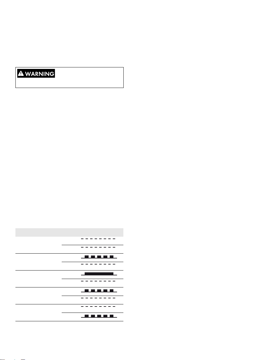
The following symbols are used in this document:
Symbol Explanation
Indicates a hazardous situation which, if not avoided, will result in death or
serious injury
Indicates a hazardous situation which, if not avoided, can result in death or
serious injury
Indicates a hazardous situation which, if not avoided, can result in minor or
moderate injury
Indicates a situation which, if not avoided, can result in property damage
Indicates that the following section contains tasks that must be performed by
qualified persons only
Information that is important for a specific topic or goal, but is not
safety-relevant
☐
☑ Desired result
✖ A problem that might occur
General Safety
Indicates a requirement for meeting a specific goal
Disconnecting the inverter
This manual contains important instructions that must be
followed during installation and maintenance of the
inverter.
Before Installation
Check the inverter and the packaging for damage. If
in doubt, contact the supplier before commencing
installation.
Installation
For optimum safety, follow the steps described in this
document. Keep in mind that the inverter has two voltage
carrying sides, the PV input and the utility grid.
12 STP60-10-IA-xx-10 Installation Guide
Before working on the inverter, disconnect it from the utility
grid by means of the main switch and switch off PV using
the integrated PV load-break switch (DC load-break
switch). Ensure that the inverter cannot be unintentionally
reconnected. Use a voltage detector to ensure that the
unit is disconnected and voltage free. The inverter can still
be charged with very high voltage at hazardous levels
even when it is disconnected from utility grid and PV
modules. Wait at least five minutes after disconnection
from the utility grid and PV modules before proceeding.
Page 13
SMA Solar Technology AG
RISK OF ELECTRIC SHOCK
These maintenance instructions are intended for use by
qualified personnel only. To reduce the risk of electric
shock, do not perform any maintenance work other than
that specified in the user manual unless you are qualified
to do so.
The inverter is not equipped with an transformer and is
intended to be installed according to NFPA 70, 690.35
with an ungrounded (floating) PV array.
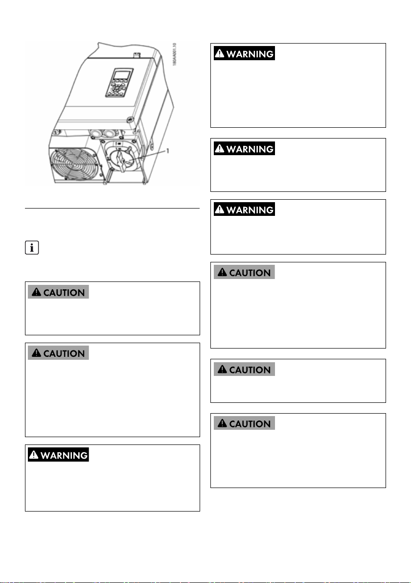
1 PV load-break switch
Figure 1.1
INFORMATION
The PV load-break switch can be secured in the ‘Off’
position using a padlock.
DC voltages up to 1,000 V are present in a PV system
even when the inverter is disconnected from the utility grid.
Faults or inappropriate use may lead to electric arcing.
MAINTENANCE AND MODIFICATION
Only authorized personnel are permitted to repair or
modify the inverter. To ensure personal safety, use only
original spare parts available from the supplier. If
no n-or igin al sp are p ar ts a re u se d, c omp li anc e wi th CE /U L
guidelines in respect of electrical safety, EMC and
machine safety is not guaranteed.
INSTALLER
Observe the National Electric Code, ANSI/NFPA 70.
Input and output circuits are isolated from the enclosure.
System grounding is the responsibility of the installer.
Input and output circuits are isolated from the enclosure.
System grounding, if required by the Canadian Electrical
Code, Part I, is the responsibility of the installer.
All persons responsible for the installation and
maintenance of inverters must be:
• Trained and authorized in general safety rules for
work on electric equipment.
• Familiar with local requirements, rules and
regulations for the installation.
The inverter does not provide overcurrent protection. This
must be provided by the installer. See table 5.8
The temperature of the cooling elements and components
in the inv ert er c an e xce ed 7 0°C /15 8°F . Th ere is a ri sk o f
burns.
The inverter is to be installed in such way that hot
components cannot be touched.
Installation Guide STP60-10-IA-xx-10 13
Page 14
SMA Solar Technology AG
INFORMATION
To reduce the risk of fire, connect the inverter only to a
circuit provided with 125 A maximum branch-circuit
overcurrent protection in accordance with the National
Electrical Code
®
, ANSI/NFPA 70.
This device has been tested and found to comply with
the thresholds for a Class B digital device, pursuant
to part 15 of the FCC Rules. These thresholds are
intended to provide an adequate level of protection
against harmful interference when using the device in
residential areas. The inverter generates, uses and
INFORMATION
Use 75°C or 90°C cables, either AWG copper or
AWG aluminum. See Section 2.7, page26.
can radiate radio frequency energy and, if not
installed and used in accordance with the
instructions, may cause harmful interference to radio
communications. However, there is no guarantee that
interference will not occur in a particular installation.
INFORMATION
The symbol for grounding conductors used in this
manual is identified in figure 2.18.
The on/off symbol is identified in Section 3.2.2,
page31.
INFORMATION
For information about the operating temperature
range, see Section 5.4, page49.
If this device does cause harmful interference to radio
or television reception, which can be determined by
turning the device off and on, the user is encouraged
to try to c orr ect the int erf ere nce by o ne o r mo re o f th e
following measures:
• Reorient or relocate the receiving antenna.
• Increase the distance between the device and
receiver.
• Do not connect the device to a circuit for radio
or television receivers.
INFORMATION
This manual contains information about field wiring
connections and torque specifications. See Section
5.5, page50.
• Consult your distributor or a trained radio/TV
technician for help.
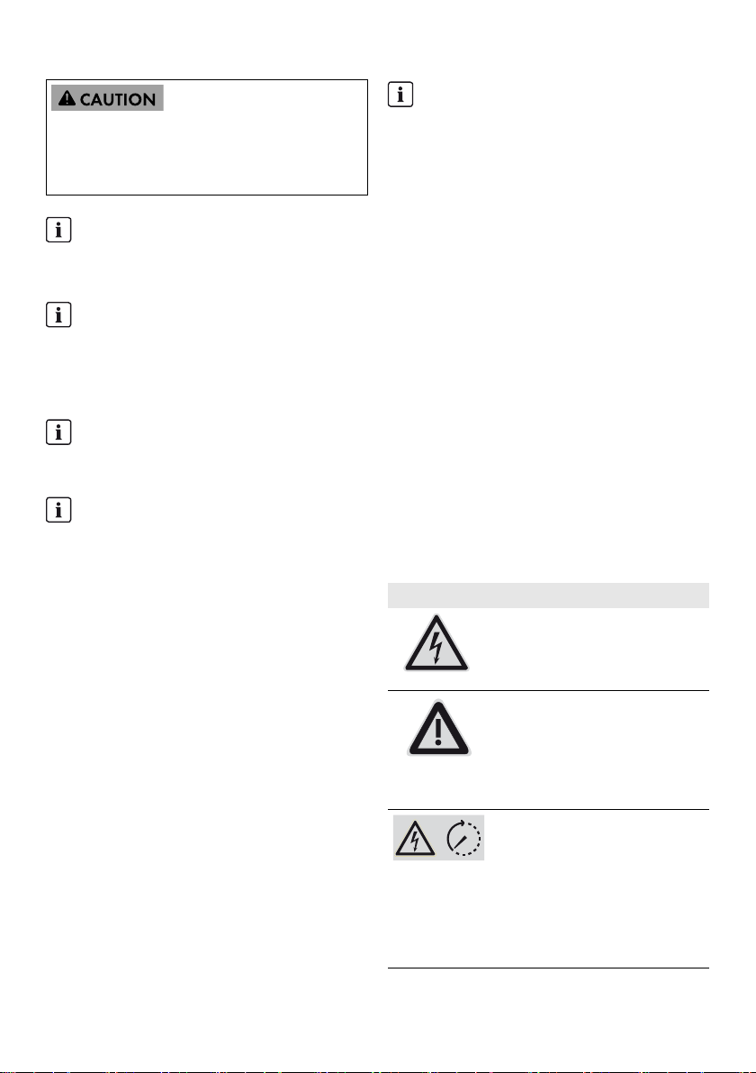
Symbols on the Inverter
Symbol Explanation
Danger to life due to electric shock
The product operates at high voltages.
All work on the product must be
carried out by qualified persons only.
Danger
This symbol indicates that the inverter
must be additionally grounded if
additional grounding or equipotential
bonding is required at the installation
site.
Danger to life due to high voltages in
the inverter; observe waiting time.
High voltages that can cause lethal
electric shocks are present in the live
components of the inverter.
Prior to performing any work on the
inverter, disconnect it from all voltage
sources as described in this document.
14 STP60-10-IA-xx-10 Installation Guide
Page 15
SMA Solar Technology AG 1 Introduction
Symbol Explanation
Risk of burns due to hot surfaces
The product can get hot during
operation. Avoid contact during
operation. Allow the product to cool
down sufficiently before carrying out
any work.
Observe the documentation
Observe all documentation supplied
with the product.
Compliance
Further information can be found in the download area of
www.SMA-Solar.com (see also Section 5, page45).
1Introduction
The STP 60 inverters are designed to act exclusively as
grid-tie inverters for PV systems. The inverter converts direct
voltage generated by a PV array to alternating current. The
device must be connected to the utility grid and a sufficient
number of PV modules in order to operate properly. The
STP 60 inverters are not suitable for any other applications
(such as operation with battery or wind turbine systems).
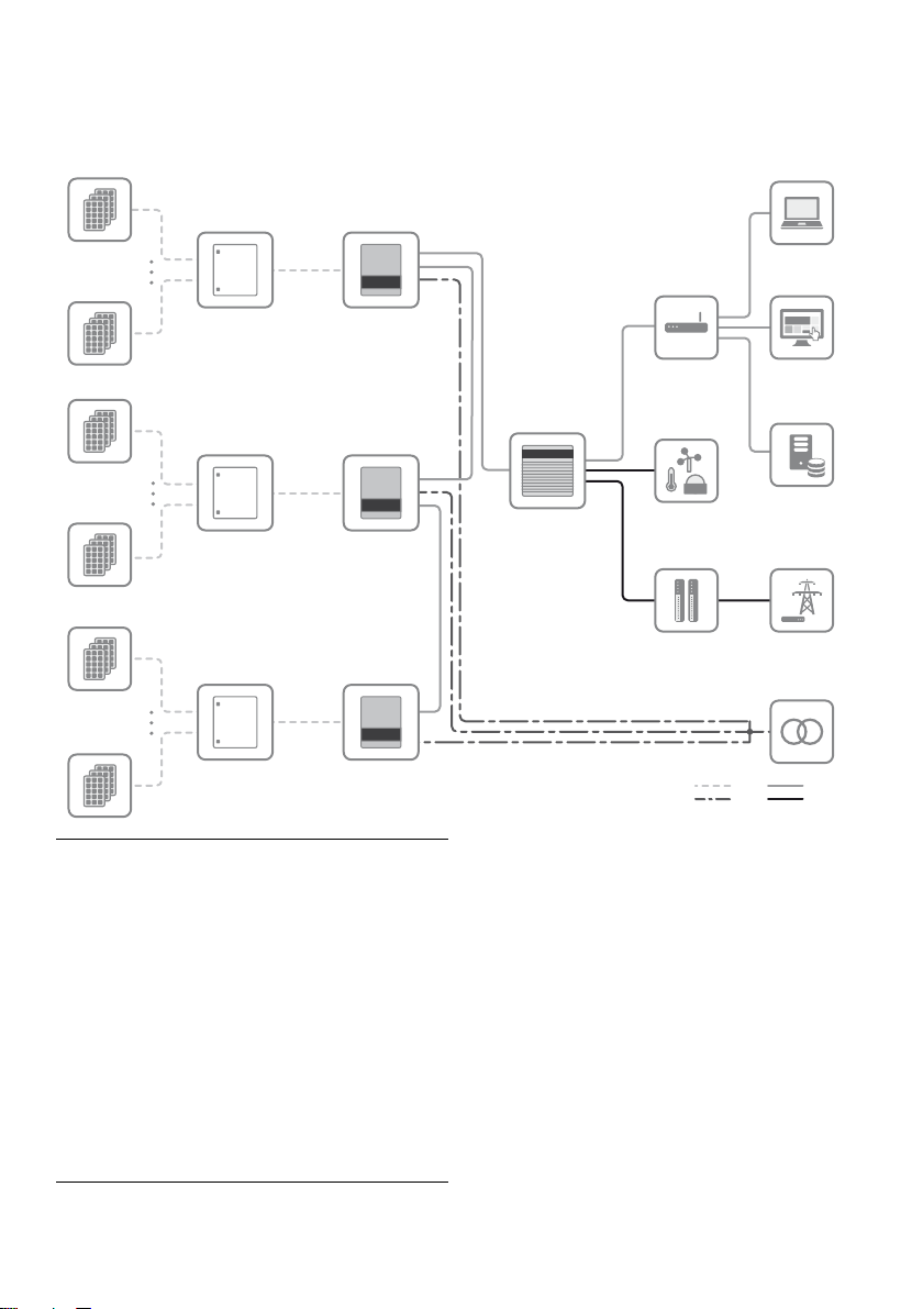
The STP 60 system consists of four main components:
• Sunny Tripower 60
• PV array junction box
The PV array junction box makes it possible to combine
the needed number of PV strings for the STP 60
inverter. A PV array junction box is needed for each
STP 60 inverter.
• SMA Inverter Manager
The SMA Inverter Manager is required for the
operation of the Sunny Tripower 60. Up to 42
Sunny Tripower 60 inverters can be connected to one
SMA Inverter Manager. The SMA Inverter Manager
handles all communication of the inverters. It serves as
central interface for data acquisition systems, upload to
cloud services and power-plant control.
• Local commissioning and service tool (LCS tool)
The LCS tool is required for commissioning and
servicing STP 60 inverters via the
SMA Inverter Manager. The LCS tool acts as the
primary user interface of the STP 60 system.
Installation Guide STP60-10-IA-xx-10 15
Page 16
1 Introduction SMA Solar Technology AG
STP 60-10
STP 60-10
STP 60-10
DC COMBINER
DC COMBINER
DC COMBINER
1
12
1
12
1
12
1
23
4
5
6
7
8
9
10
11
12
INVERTER-
MANAGER
DC
AC
ETHERNET
RS485
I/O BOX
TRANSFORMER
STATION
PV STRINGS
PORTAL
LCS TOOL
ROUTER
GRID
MANAGEMENT
PV STRINGS
PV STRINGS
WEATHER
STATION
SCADA
SYSTEM
1.1 Overview of Installation Area
1PV strings
2 PV array junction box
3 Sunny Tripower 60
4 SMA Inverter Manager
5Router
6 LCS tool
7Portal
8 SCADA system
9 Weather station
10 I/O box
11 Grid management
12 Transformer station
16 STP60-10-IA-xx-10 Installation Guide
1.2 Purpose of the Manual
The installation manual provides information on the
installation and commissioning of the STP 60 inverter series.
Additional resources available:
• Quick reference guide for commissioning of the STP 60
inverters – for information required to commission the
STP 60 inverters as well as setup of inverter
communication.
• Installation manual of the SMA Inverter Manager and
the I/O box – for information required to commission
the STP 60 inverter as well as setup of inverter
communication
• Planning guidelines – for information required for
detailed inverter layout planning in a diversity of solar
energy applications.
Page 17
SMA Solar Technology AG 1 Introduction
• Service manual for replacing the fan – for information
required to replace a fan.
• Service manual for replacing the SPDs – for
information required to replace surge protection
devices.
These documents are available from the download area at
www.SMA-Solar.com or from the supplier of the PV inverter.
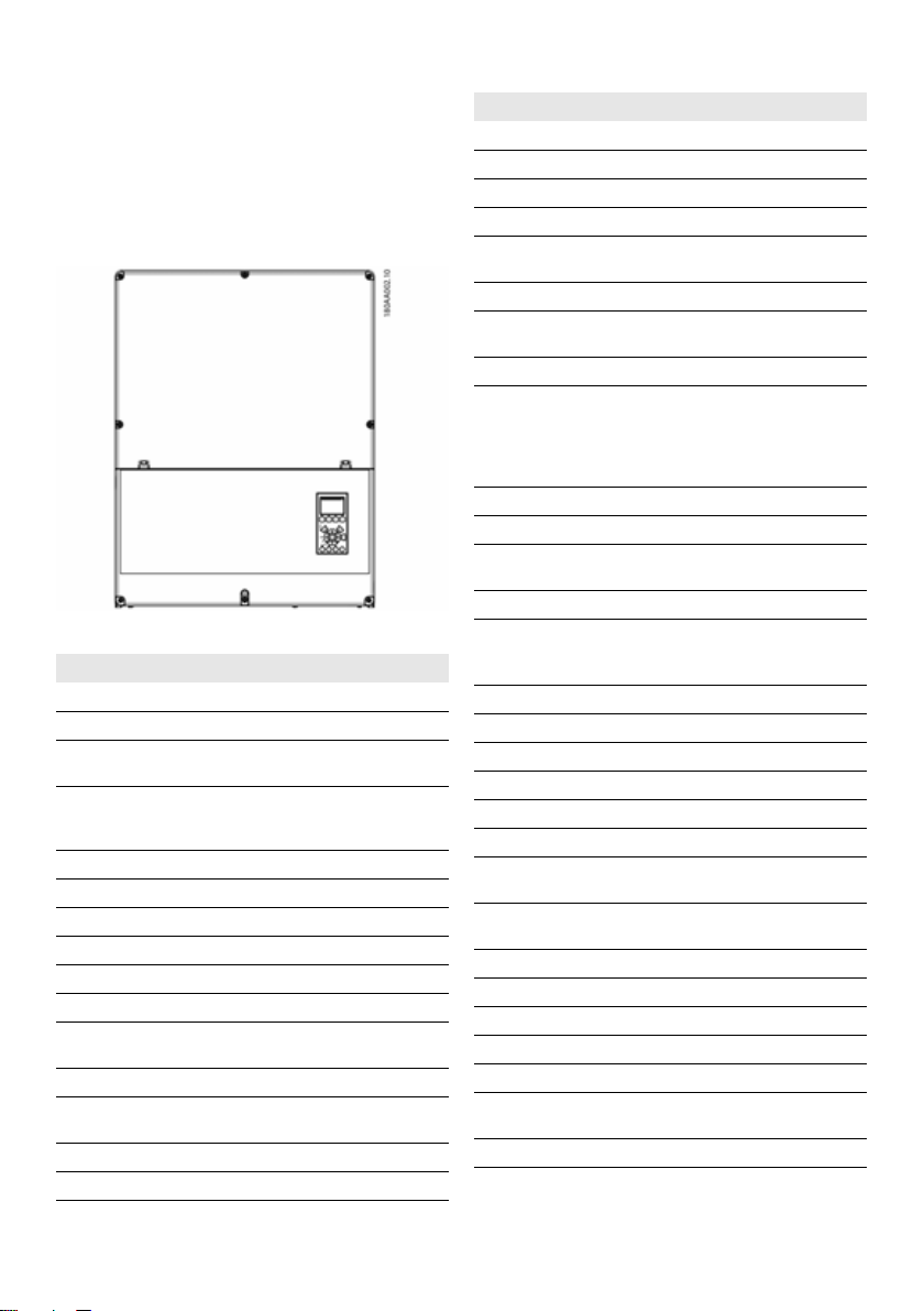
Figure 1.2 Sunny Tripower 60
Abbreviation Description
ANSI American National Standards Institute
AWG American Wire Gauge
cat5e Category 5 twisted pair cable (enhanced) for
DHCP Dynamic Host Configuration Protocol –
DGO Distribution Grid Operator
DSL Digital Subscriber Line
EMC (directive) Electromagnetic compatibility directive
ESD Electrostatic Discharge
FCC Federal Communications Commission
FRT Fault Ride Through
GSM Global System for Mobile Communications
HDD Hard Disk Drive
IEC International Electrotechnical Commission –
IT Isolated Terra
LCS Local Commissioning and Service
data transmission
enables automatic assignment of the network
address via the DHCP server
(standard for digital cellular mobile network)
international standards organization
Abbreviation Description
LED Light-Emitting Diode
LVD (Directive) Low voltage directive
MCB Circuit Breaker
MPP Maximum Power Point
MPPT Maximum Power Point Tracking determines the
NFPA National Fire Protection Association
P P is the symbol for active power and is
PCB Printed Circuit Board
PCC Point of Common Coupling - point of
PE Protective Grounding
PELV Protected Extra-Low Voltage
PLA Power Level Adjustment = Output power
P
nom
POC Point of Connection
P
STC
PV Photovoltaic, photovoltaic cells
RCD Residual-Current Device
RCMU Residual Current Monitoring Unit
R
ISO
ROCOF Rate of Change of Frequency
Q Q is the symbol for reactive power and is
S S is the symbol for apparent power and is
STC Standard Test Conditions
SW Software
THD Total Harmonic Distortion
TN-S Terra Neutral - Separate. AC Network
TN-C Terra Neutral - Combined. AC Network
TN-C-S Terra Neutral - Combined - Separate. AC
TT Terra Terra. AC Network
point of optimum PV power
measured in Watts (W).
interconnection
The point on the public electricity network to
which other customers are, or could be,
connected.
limitation
Power [W], Nominal active power
The point at which the PV system is connected
to the public utility grid.
Power [W], Standard Test Conditions
Insulation resistance
measured in reactive volt-amperes (VAr).
measured in volt-amperes (VA).
Network
Installation Guide STP60-10-IA-xx-10 17
Page 18
1 Introduction SMA Solar Technology AG
1.3 Unpacking
Content:
•Inverters
•Wall mounting bracket
• Accessories bag containing:
– 6 wall plugs 8 x 50 mm
– 6 mounting screws 6 x 60 mm
– 1 M25 cable gland with sealing grommet for
Ethernet cables
– 1 grounding bolt M6 x 12 mm
– For STP 60-10-US additionally included: 2 x cable
channel with conduit bracket (2")
• Installation manual
• Quick reference guide for installation
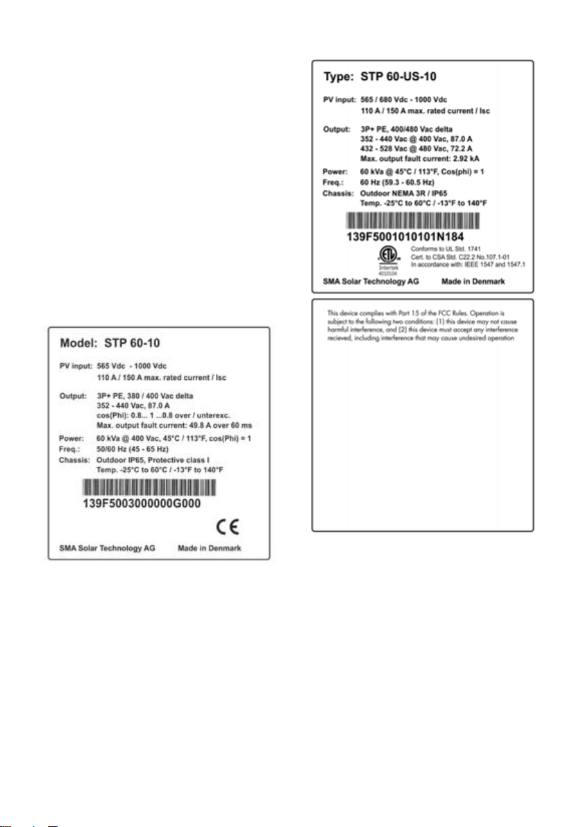
1.4 Inverter Type Label
Figure 1.4 Sunny Tripower 60-US type label
Figure 1.3 Sunny Tripower 60 type label
18 STP60-10-IA-xx-10 Installation Guide
The type label on the side of the inverter shows:
•Device type
• Important technical data
•Serial number, located under the bar code, for inverter
identification
Page 19

SMA Solar Technology AG 1 Introduction
1.5 Installation Sequence
1. Pay special attention to the important safety
information at the beginning of this manual.
2. Mount the inverter according to Section 2.1, page21,
Section 2.2, page22, Section 2.3, page23.
3. Open the inverter in accordance with Section 2.5,
page24.
4. Install the AC supply in accordance with Section 2.6,
page25.
5. Install Ethernet in accordance with Section 5.8,
page52.
6. Install the PV module in accordance with Section 2.9,
page27 using a PV array junction box.
7. Close the inverter in accordance with Section 2.5,
page24.
8. Turn on AC.
9. Finalize commissioning by using the Local
Commissioning and Service Tool (LCS tool). The tool is
available from the download area at
www.SMA-Solar.com. The hardware requirements for
the LCS tool are:
– PC with Windows
–1 GB HDD
–2 GB RAM
The LCS tool must be installed on a local PC drive. The
PC must be connected to the system network of the
SMA Inverter Manager. For setup via the LCS tool,
refer to Section 3.3, page31.
10. Switch on the PV system via the PV load-break switch.
11. Verify the installation by:
– Inverter display: LED "On" is permanently green.
– LCS tool: In the inverter view, the status is "On
grid".
12. The inverter is in operation now.
TM
7 and later
Installation Guide STP60-10-IA-xx-10 19
Page 20

1 Introduction SMA Solar Technology AG
Figure 1.5 Overview of the installation area
PELV (safe to touch)
2 Device grounding
7 Ethernet interface x 2
8 RS-485 interface (not in use)
Live Parts
1AC terminals
5PV terminals
Other
3 AC overvoltage protection (SPDs)
4 DC overvoltage protection (SPDs)
6 PV load-break switch
Figure 1.2 Overview of the installation area
20 STP60-10-IA-xx-10 Installation Guide
Page 21
SMA Solar Technology AG 2 Installation
2Installation
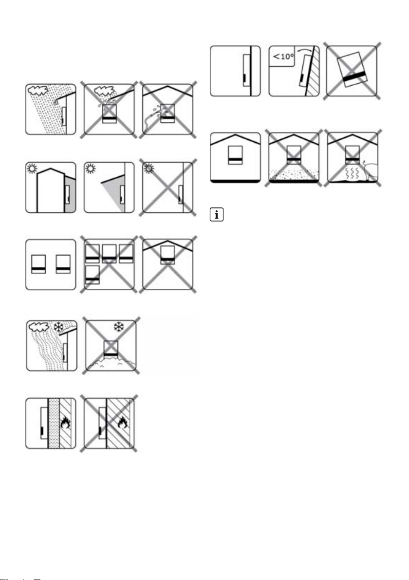
2.1 Environment and Clearances
Figure 2.6 Mount upright on vertical surface. Backwards tilt of up to
ten degrees is permitted.
Figure 2.1 Avoid constant contact with water
Figure 2.7 Prevent dust and ammonia gases
Figure 2.2 Avoid direct solar irradiation
Figure 2.3 Ensure adequate air flow
Figure 2.4 Ensure adequate air flow
Figure 2.5 Mount on non-flammable surface
INFORMATION
When planning the installation site, ensure that the
inverter product label and warning labels remain
visible. For detailed information, see Section 5,
page45.
Installation Guide STP60-10-IA-xx-10 21
Page 22
2 Installation SMA Solar Technology AG
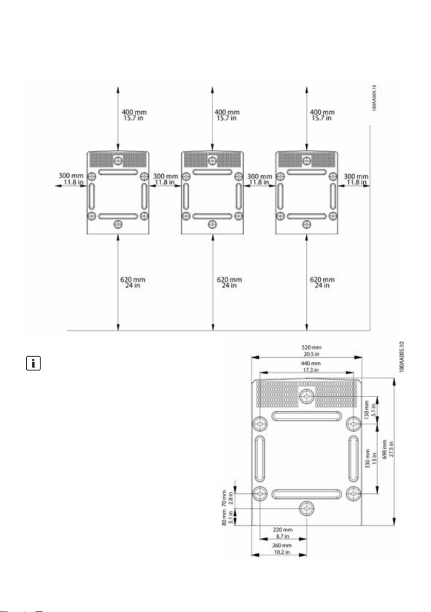
2.2 Mounting the Wall Mounting
Bracket
Figure 2.8 Safety clearances
INFORMATION
Ensure 620 mm/24 inches base clearance for
adequate airflow.
22 STP60-10-IA-xx-10 Installation Guide
Page 23
SMA Solar Technology AG 2 Installation
Figure 2.9 Wall mounting bracket
INFORMATION
Use of the wall mounting bracket delivered with the
inverter is mandatory. If the inverter is mounted
without the wall mounting bracket, the warranty
becomes void. It is highly recommended to use all six
mounting holes.
Mounting of the wall mounting bracket:
• Mount the wall mounting bracket in the defined
environment
• Use screws and wall plugs that can safely carry the
weight of the inverter.
• Ensure that the mounting plate is correctly aligned.
• Observe safe clearances when installing one more
inverters, to ensure adequate airflow. Clearances are
specified in figure 2.8 and on the mounting plate label.
• Mounting multiple inverters side by side in a single row
is recommended. Contact the supplier for guidelines
when mounting inverters in more than one row.
• Ensure adequate clearance at the front, for safe
installation and service access to the inverter.
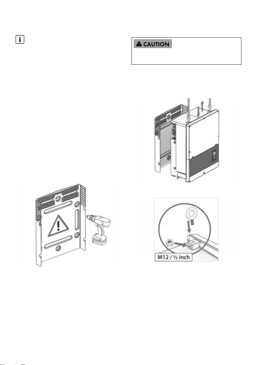
2.3 Mounting the Inverter
Refer to local health and safety regulations when
handling the inverter.
Procedure:
1. Lift the inverter. Locate the slots on the side of the wall
mounting bracket. Use M12 or ½ in lifting bolts and
matching nuts (not included in the scope of delivery).
Figure 2.11 Position the inverter
Figure 2.12 Lifting bolts
Figure 2.10 Mounting of the wall mounting bracket
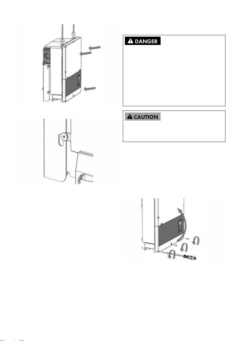
2. On the inverter, position the side screws against the
wall mounting bracket slots.
3. Push the inverter as shown so the side screws slide into
the two lower slots and the two upper slots. See figure
2.13 and figure 2.14
Installation Guide STP60-10-IA-xx-10 23
Page 24
2 Installation SMA Solar Technology AG
2.5 Access to the Installation Area
Before working on the inverter, disconnect it from the utility
grid by means of the main switch and switch off PV using
the integrated PV load-break switch (DC load-break
switch). Ensure that the inverter cannot be unintentionally
reconnected. Use a voltage detector to ensure that the
unit is disconnected and voltage free. The inverter can still
be charged with very high voltage at hazardous levels
even when it is disconnected from utility grid and PV
modules. Wait at least five minutes after disconnection
from the utility grid and PV modules before proceeding.
Figure 2.13 Sliding the screws into the slots
Observe ESD safety regulations. Discharge any
electrostatic charge by touching the grounded enclosure,
before handling any electronic component.
Procedure:
1. To open the cover, loosen the three lower front screws
using a TX 30 screwdriver. The screws are captive
screws and cannot fall out.
2. Ope n th e co ver and fla p it bac k. A mag net e nab les the
cover to stay open.
Figure 2.14 Detail of sliding into slot
3. To close the cover, lower it into place and fasten the
three front screws.
4. Check that the four side screws sit securely in the
mounting plate slots.
5. Release the inverter.
2.4 Disassembling the Inverter
Procedure:
1. Disassemble the inverter in the reverse mounting order.
2. Lif t an d sl ide the inv ert er o ut o f th e mo unt ing pla te s lot s.
3. Lift the inverter free of the mounting plate.
Figure 2.15 Loosen front screws and lift the cover
24 STP60-10-IA-xx-10 Installation Guide
Page 25
SMA Solar Technology AG 2 Installation
2.6 Grid Connection
These instructions for utility grid connection are for
qualified personnel only. To reduce the risk of electric
shock, do not perform any maintenance work other than
that specified in the user manual unless you are qualified
to do so.
For fuse and RCD information, refer to Section 5,
page45. AC fuse rating must not exceed the ampacity of
the conductors used.
INFORMATION
All electrical installations in the U.S. and Canada
must be made in accordance with the local standards
and National Electrical Code
the Canadian Electrical Code
®
ANSI/NFPA70 or
®
CSA C22.1.
• Before connecting the inverter to the utility grid,
contact your local grid operator. The electrical
conn ectio n of th e inve rter mus t be ca rried out by
qualified persons only.
• Ensure that no cables used for electrical
connection are damaged.
IMI Detection
The inverter has built-in IMI/RCMU (Insulation Monitoring
Interrupter / Residual Current Monitoring Unit) according to
the UL 1741 for non-isolated EPS interactive PV inverters. It
acts on continuous ground fault current and a sudden
change in the ground fault current. This functionality is
activated during normal operation.
Insulation Resistance Detection
The inverter has a built-in insulation resistance detection /
ISO circuit, which is certified according to the UL 1741 for
non-isolated EPS interactive PV inverters. The insulation
resistance detector performs a measurement of the
connected PV system resistance to ground before the
inverter connects to the grid. If the resistance is below the
gr id c ode set val ue, the inv erter wil l wa it a nd r e-m eas ure the
resistance after a short while. When the resistance is above
the grid code set value, the inverter performs a self-test and
connects to the grid.
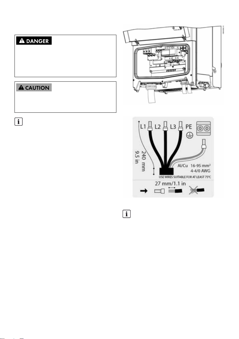
Figure 2.16 Installation area
Figure 2.17 AC cable wire strip
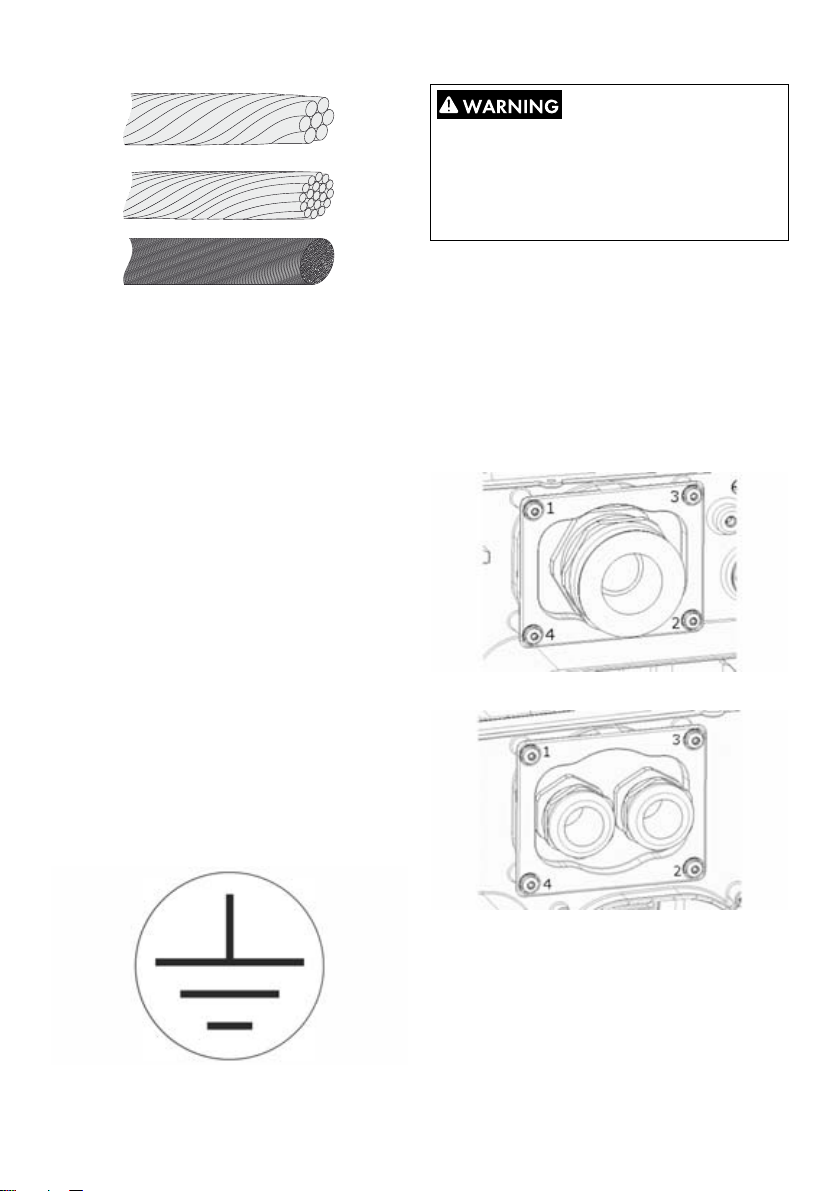
INFORMATION
For AC connection, cables with multi-strand,
fine-strand or extra fine-strand conductors can be
used (see figure 2.18).
When using fine-strand or extra fine-strand
conductors, bootlace ferrules must be used for the
connection.
Installation Guide STP60-10-IA-xx-10 25
Page 26
2 Installation SMA Solar Technology AG
LEAKAGE CURRENT HAZARD
Leakage currents exceed 3.5 mA. Failure to ground the
inverter properly can result in death or serious injury.
• Ensure the correct grounding of the devices by a
certified electrical installer.
2.7 Cable Entry
Figure 2.18 Cables with different conductors (from top to bottom):
single strand, multi strand, fine stand and extra-fine strand
The STP 60 inverter must only be connected to a
three-phase grid.
On the AC cable, strip insulation on all four wires. The
protective conductor (PE) must be longer than the grid wires.
See figure 2.17.
1. Verify that the nominal voltage of the inverter matches
the grid voltage.
2. Ensure that the main circuit breaker is released, and
take precautions to prevent reconnection.
3. Open the front cover.
4. Insert the cable through the AC cable gland to the
connecting terminal plate.
5. Connect the three grid wires (L1, L2, L3) and the
grounding conductor (PE) to the connecting terminal
plate with the respective markings. The grounding
conductor is marked with the symbol shown in figure
2.19.
6. Optional: Make an extra PE connection at the
secondary PE grounding points using the external
device grounding bolt delivered with the inverter. See
figure 5.2.
7. All wires must be properly fastened with the correct
torque. See Section 5.5, page50.
Options for cable entry
• For STP 60-10: cable glands (pre-mounted)
• For STP 60-10-US: two-inch conduit adapters (included
in delivery)
When replacing the two-inch conduit adapters, ensure to
tighten the screws in the order shown in figure 2.19 and
figure 2.20. First tighten all screws with 0.75 Nm and then
2.5 Nm.
Figure 2.20 AC mounting bracket
Figure 2.21 DC mounting bracket
Figure 2.19 Protective conductor symbol
26 STP60-10-IA-xx-10 Installation Guide
Page 27
SMA Solar Technology AG 2 Installation
Terminal Range
AC+PE 16 to 95 mm²
PV 16 to 95 mm²
Table 2.1 Suitable conductor sizes
1)
Always observe the ampacity of cables used.
1)
6 to 4/0 AWG
6 to 4/0 AWG
Max. conductor
temperature rating
90ºC Al/Cu 37 to 44 mm
90ºC Al/Cu 14 to 21 mm
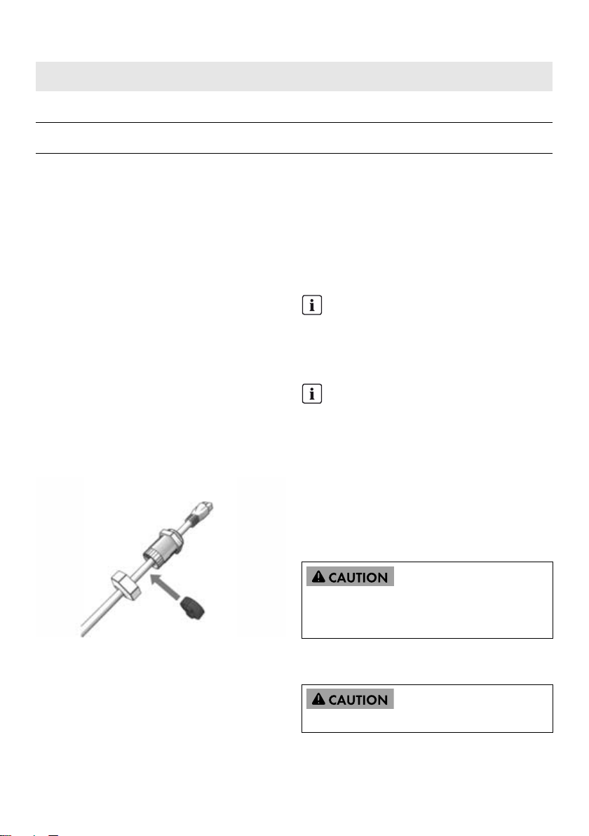
2.8 Ethernet Connections
For outdoor use, ensure that an appropriate cable is used.
If the cable is very stiff, an intermediate terminal should be
used in order to change from a stiff to a more flexible cable
before entering the inverter. For some cables it might be
sufficient to remove the hard outer mantle of the part of the
cable inside the inverter enclosure. This is to protect the
PCB-mounted RJ-45 Ethernet ports from excessive strain,
which could lead to damage or connection issues.
Procedure:
1. Do not remove the RJ-45 connector on the Ethernet
cable.
2. Run the cables through the base of the inverter via
cable glands. See figure 2.22.
3. Cut slice in rubber grommet. Place the grommet in the
gland to ensure proper seal.
4. Plug into the Ethernet connector.
Conductor
material
Cable sheath diameter with supplied
cable gland
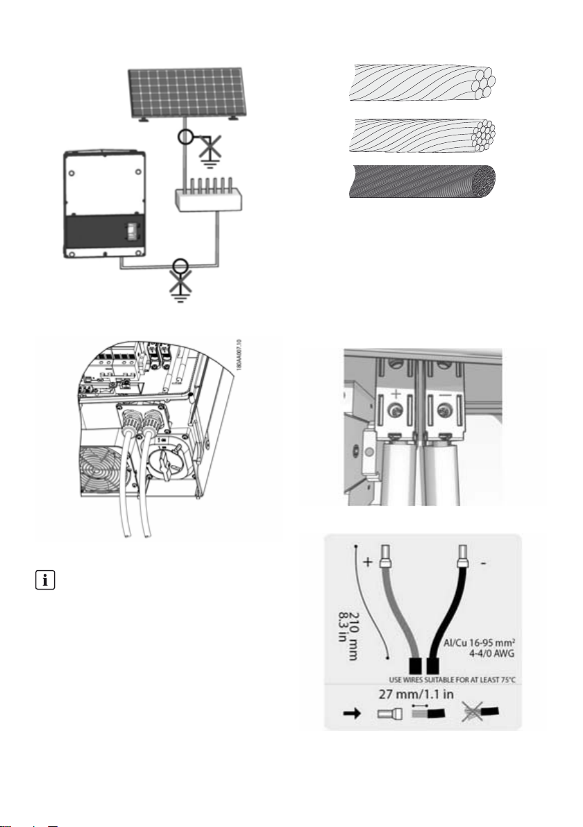
2.9 PV Connection
2.9.1 External PV Array Junction Boxes
PV str ing s mu st b e co nne cte d to the DC i npu t vi a an ext ern al
PV array junction box. The PV array junction box connects
the PV strings of the PV array and protects the individual
strings against overcurrent.
INFORMATION
The same number and type of modules must be
connected to all PV strings connected to the PV array
junction box. In addition, all connected modules must
have the same orientation.
INFORMATION
Observe correct fuse rating. Consult module
manufacturers' manuals for information on correct
string fuse rating.
Use a suitable voltage detector that can measure up to
1,000 V DC. Verify the polarity and maximum voltage of
the PV arrays by measuring the PV open-circuit voltage. The
inverter is protected against reversed polarity and will not
generate power until the polarity is correct.
The combined output from the DC combiner must be
connected to the DC input of the STP 60 inverter.
PV array is floating, with both the (+) and (-) conductors
connected to the inverters' PV inputs. Neither conductor is
connected to ground.
Figure 2.22 Run cables through cable glands
The DC power can be disconnected with the
inverter-integrated DC load-break switch.
Do NOT connect PV to ground!
Installation Guide STP60-10-IA-xx-10 27
Page 28
2 Installation SMA Solar Technology AG
Figure 2.26 Cables with different conductors (from top to bottom):
single strand, multi strand, fine strand and extra fine strand
1. On the inverter or PV array junction box turn the PV
load-break switch to Off position.
2. Connect the PV cables from the PV array junction box
to the inverter. Ensure correct polarity, see figure 2.27.
Figure 2.24 Do not connect PV to ground!
3. All wires must be properly fastened with the correct
torque. See Section 5.5, page50.
Figure 2.27 Connect to PV input
Figure 2.25: DC connection area
INFORMATION
Cables with multi-strand, fine-strand or extra
fine-strand conductors can be used for AC
connection (see figure 2.26).
When using fine-strand or extra fine-strand
conductors, bootlace ferrules must be used for the
connection.
Figure 2.28 DC label
28 STP60-10-IA-xx-10 Installation Guide
Page 29
SMA Solar Technology AG 3 Initial Setup and Start
Protection class of PV modules
The inverter must only be operated with PV modules of
protection class II, compliant with IEC 61730, application
class A.
Only connect PV modules to the inverter. Other energy
sources are not allowed.
PV modules generate a voltage when exposed to light.
2.10 Closure
1. Close the cover of the inverter installation area. Fasten
the three front screws. See Section 5.5, page50.
2. Turn on AC power.
3 Initial Setup and Start
3.1 User Interface
The user interface comprises:
• Local display, for all inverter variants. The local display
shows status information of the inverter. It is not
possible to configure or set up the STP 60 inverter via
the display. The "#" in the display explains the
operation modes.
• Local commissioning and service tool (LCS tool). The
LCS tool enables configuration of one or multiple
STP 60 inverters.
3.1.1 Operating Modes
The inverter has five operation modes, indicated by LEDs.
Status LEDs LEDs
Off grid Green
Red
Connecting Green
Red
On grid Green
Red
Internal inverter event Green
Red
Fail safe Green
Red
Off grid (standby) (LEDs off)
#0-51
When no power has been delivered to the utility grid for
more than ten minutes, the inverter disconnects from the grid
and shuts down. User and communication interfaces remain
powered for communication purposes.
Connecting (green LED flashing)
#52 to 53
The inverter starts up when the PV input voltage reaches the
minimum DC feed-in voltage. The inverter performs a series
of internal self-tests, including measurement of the resistance
between the PV arrays and ground. Meanwhile, it also
monitors the grid parameters. When the grid parameters
have been within the specifications for the required amount
of time (depends on grid code), the inverter starts feeding
into the utility grid.
On grid (green LED on)
#60
The inverter is connected to the utility grid and feeds into the
utility grid. The inverter disconnects when:
• it detects abnormal grid conditions (dependent on grid
code),
• an internal event occurs, or
• PV power is insufficient (no power is supplied to the
grid for ten minutes).
The inverter then enters connecting mode or off-grid mode.
Internal inverter event (green LED flashing)
#54
The inverter is waiting for an internal condition to be within
thresholds (for example when the temperature is too high)
before it re-connects to the utility grid.
Fail safe (red LED flashing)
#70
If the inv ert er d ete cts an e rror i n it s ci rcu its dur ing the sel f-test
(in connecting mode) or during operation, the inverter goes
into fail s afe mo de, disc onnec ting f rom t he gri d. The in verter
will remain in "fail safe" mode until power has been absent
for a minimum of ten minutes, or the inverter has been shut
down completely (AC+PV).
Table 3.1 Operating modes
Installation Guide STP60-10-IA-xx-10 29
Page 30
3 Initial Setup and Start SMA Solar Technology AG
3.2 Display
INFORMATION
It can take up to ten seconds until the display
activates, after start-up.
The integrated display on the inverter front gives the user
access to information about the PV system and the inverter.
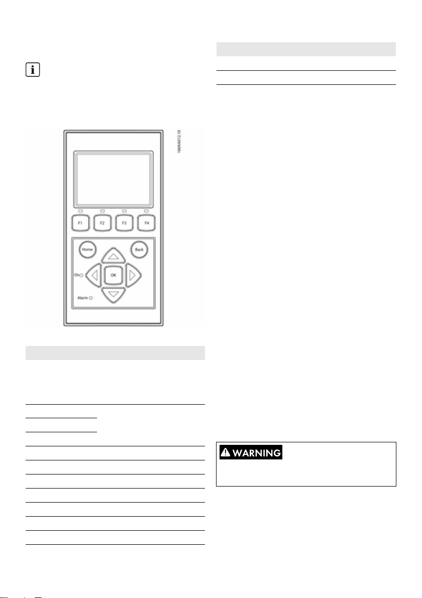
Figure 3.1 Overview of display buttons and functionality
Display buttons and functionality
Button Function
F1 Adjust the contrast level of
display. Use arrow up/down
button while pressing the F1
button.
F2 No function
F3
F4
Home Return to main screen
OK No function
Arrow up A step up
Arrow down A step down
Arrow right Toggles screen right
Arrow left Toggles screen left
Back Return to main screen
Button Function
On - green LED
Alarm - red LED
Table 3.2: Display buttons and functionality
The screen structure is divided into three sections:
1. Main screen. Current and daily yield. This section
contains:
– Actual output power (kW)
– Yield of the current day (kWh)
– Total yield (kWh)
– Current date
– Current time
– Operating mode (#)
2. Inverter information. This section contains:
– Inverter device type
–Inverter name
–Serial number
– IP address
– MAC address of the SMA Inverter Manager
– Inverter software version
3. Actual values. This section contains:
– PV voltage and current
– Phase-to-phase voltages
– Phase currents
– Power frequency
3.2.1 Initial Setup via LCS tool
The LCS tool makes it possible to chose from a list of
predefined settings for different grids. All grid-specific limits
must be configured using the LCS tool.
After installation, check all cables and close the inverter.
Turn on AC power.
The correct selection of the grid code is essential to
comply with local and national standards.
30 STP60-10-IA-xx-10 Installation Guide
Page 31

SMA Solar Technology AG 3 Initial Setup and Start
3.2.2 Switching on the PV Load-Break Switch
Figure 3.2. PV load-break switch
Switch on the PV load-break switch on, either via inverter or
PV array junction box.
3.2.3 Commissioning
The inverter starts automatically if sufficient solar irradiation
is ava ila ble . Co mmi ssi oning tak es a few min ute s. D uri ng t his
period, the inverter performs a self-test.
INFORMATION
The inverter is equipped with reverse polarity
protection. The inverter does not generate feed-in
power until any reverse polarity is corrected.
3.3 LCS tool
The STP 60 inverters and the SMA Inverter Manager must
be commissioned via the local commissioning and service
tool (LCS tool). Commissioning is required before the
STP 60 inverters are connected to the utility grid and start to
feed-in power.
The LCS tool is available in the download area at
www.SMA-Solar.com.
The hardware requirements for the LCS tool are:
• PC with Windows
•1 GB HDD
• 2 GB RAM
The LCS tool must be installed on a local PC drive. The PC
must be connected to the SMA Inverter Manager’s LAN 1
port via Ethernet.
TM
7 and later
INFORMATION
The SMA Inverter Manager must have an IP address
assigned by a DHCP server on port LAN 1.
It is important that the PC running the LCS tool is
connected to the same IP subnet as the
SMA Inverter Manager.
Port LAN 2 is intended for STP 60 inverters only.
Installation Guide STP60-10-IA-xx-10 31
Page 32
3 Initial Setup and Start SMA Solar Technology AG
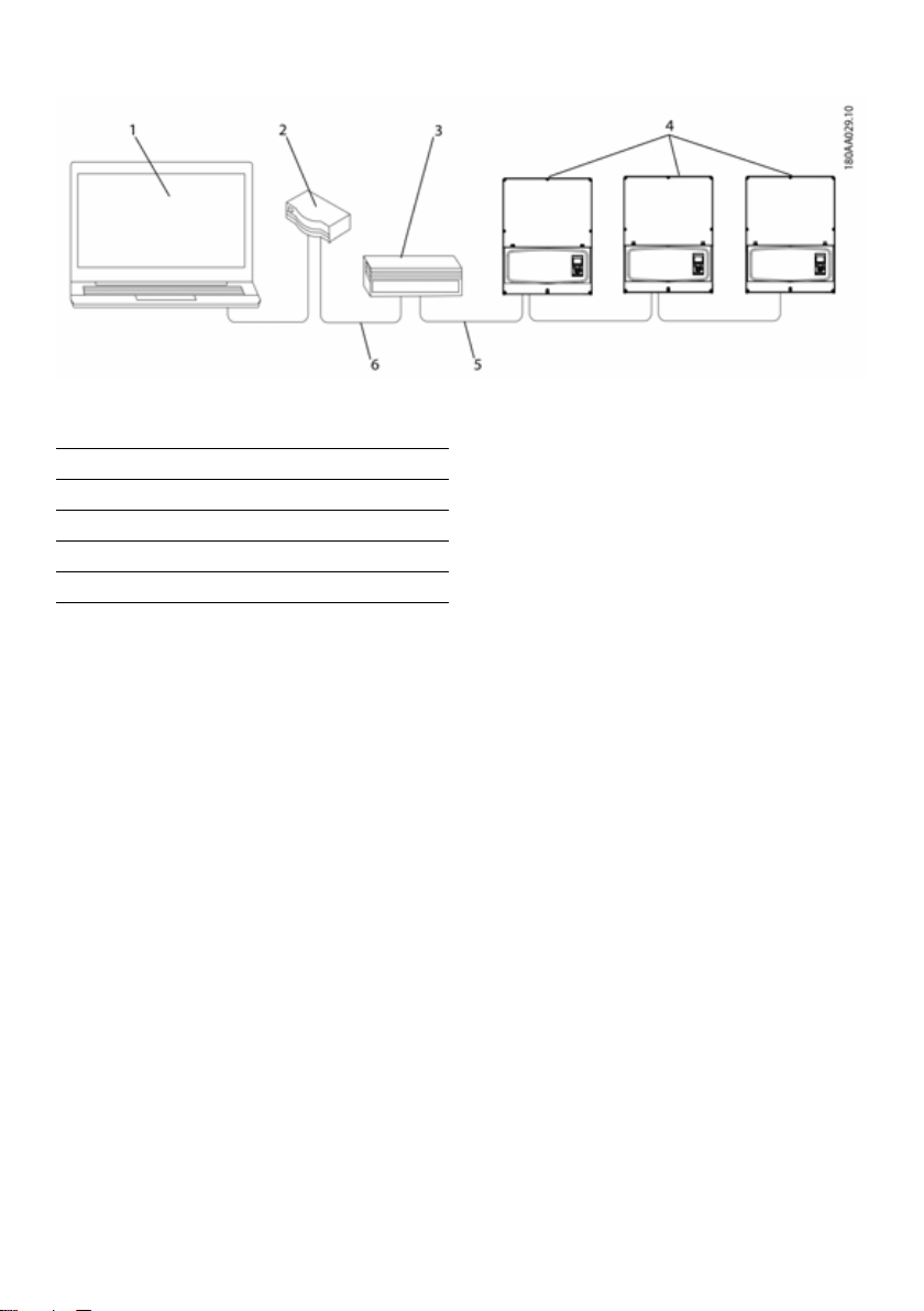
Figure 3.3: Commissioning inverters via the LCS tool
1LCS tool
2Router/DHCP
3 SMA Inverter Manager
4 Sunny Tripower 60
5LAN 2
6LAN 1
32 STP60-10-IA-xx-10 Installation Guide
Page 33

SMA Solar Technology AG 3 Initial Setup and Start
3.3.1 Getting Started
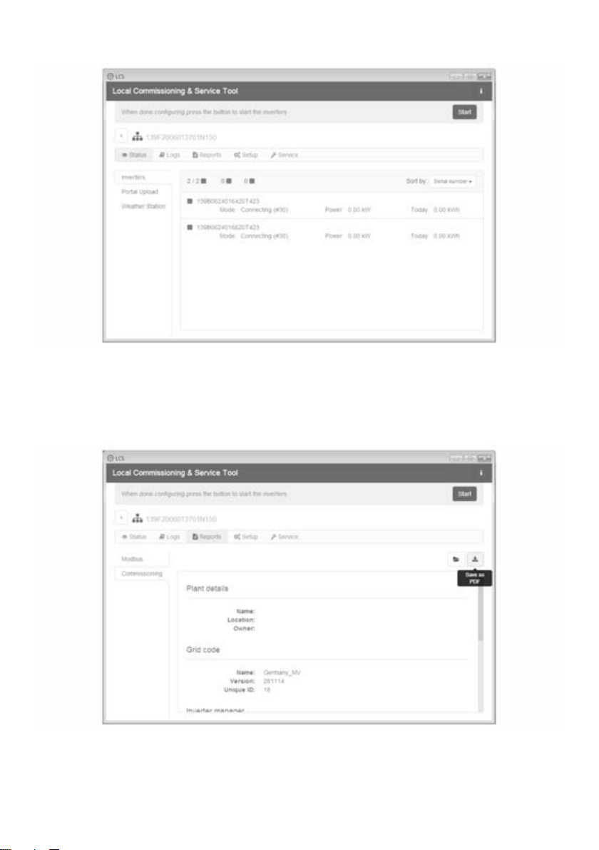
1. Start up the LCS tool. The tool displays a list of all
identified SMA Inverter Managers. It can take several
minutes before the LCS tool has identified all
SMA Inverter Managers.
2. The screen now shows a list of all
SMA Inverter Managers (see figure 3.4). To start the
wizard, click the SMA Inverter Manager to be
configured. By clicking the SMA Inverter Manager, the
inverters detected by the SMA Inverter Manager are
displayed. Uncommissioned inverters (no grid code
assigned) are presented with a blue square together
with their software version.
Figure 3.4 LCS tool - initial screen
Installation Guide STP60-10-IA-xx-10 33
Page 34
3 Initial Setup and Start SMA Solar Technology AG
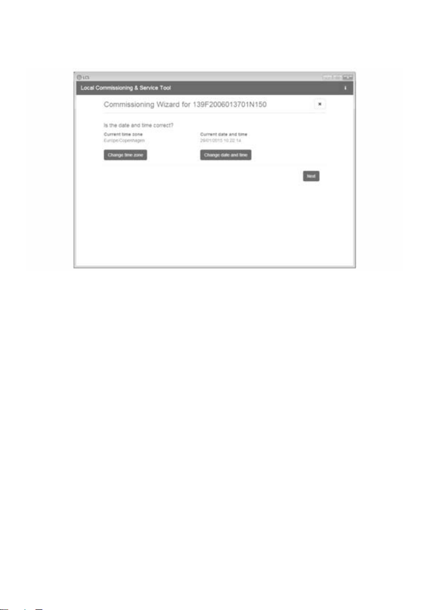
3. Verify that date and time are correct. If not, set date
and time and continue. See figure 3.5.
Figure 3.5 LCS tool - Verifying date and time
4. A list of inverters identified by the selected
SMA Inverter Manager is shown. See figure 3.6
Make sure that the list of inverters is complete.
Make sure that all inverters are present. It is possible to
continue the configuration of the listed inverters even if not
all inverters are discovered. The undetected inverters can
always be configured later.
34 STP60-10-IA-xx-10 Installation Guide
Page 35

SMA Solar Technology AG 3 Initial Setup and Start
Figure 3.6 LCS tool - List of connected inverters
5. Select the desired country from the list of options
available for the inverters in the network. See figure
3.7.
Figure 3.7 LCS tool - Select country and grid code
6. Select the desired grid code from the list of options
available for the selected country. If needed, load a
customer-specific grid code by clicking the "Load"
button. See figure 3.7. The "Create" button is inactive
and cannot be used.
7. The LCS to ol prom pts for a c onfirmat ion of the selected
country and grid code. See figure 3.8. Incorrect
configuration can be changed using the "Back" button
and changing the settings in the previous windows.
Installation Guide STP60-10-IA-xx-10 35
Page 36

3 Initial Setup and Start SMA Solar Technology AG
Figure 3.8 LCS tool - Verification of country and grid code
8. The system now applies the selected grid code to the
SMA Inverter Manager and the discovered inverters.
Any inverter added at a later stage automatically
inherits the same grid code. Only one grid code is
possible per SMA Inverter Manager.
INFORMATION
It is essential to choose the correct grid code. The grid
code cannot be changed afterwards without
contacting SMA Solar Technology AG.
9. A green square identifies the commissioned inverters.
However, the inverters are not connected to grid
before a " Start" comm and is iss ued fro m the ba r below
the top menu. See figure 3.9.
36 STP60-10-IA-xx-10 Installation Guide
Page 37
SMA Solar Technology AG 3 Initial Setup and Start
Figure 3.9 LCS tool - List of all inverters connected to the
SMA Inverter Manager
10. If sufficient PV power is present and the grid code
conditions are met, the inverters are connected to the
grid.
Figure 3.10 LCS tool - Commissioning report
11. Upon commissioning, it is possible to download a
commissioning report under the menu "Reports". The
report contains information about inverter settings,
including actual disconnection values for each inverter.
See figure 3.10.
Installation Guide STP60-10-IA-xx-10 37
Page 38

3 Initial Setup and Start SMA Solar Technology AG
INFORMATION
If the desired grid code is not available, or if the LCS
tool displays a warning about incompatible software
versions, the grid code and software library must be
updated on the LCS tool.
It is possible to set up customer specific grid code files
with adapted setting values. For this purpose, please
contact SMA Technology AG.
38 STP60-10-IA-xx-10 Installation Guide
Page 39

SMA Solar Technology AG 4 Service
4Service
4.1 Troubleshooting
The information is organized in tables showing messages
appearing in the LCS tool, known as events. The tables
contain descriptions of events as well as explanations of
which actions to take when an event occurs.
Type of event Indicates whether the event relates to grid, PV, internal or fail safe issues.
ID The specific event ID.
Display Text shown in display.
Description Description of the event.
Measure Description of which action to take prior to contacting any other parties.
DGO If the prescribed action has not identified the malfunction, contact the DGO for further assistance.
Hotline If the prescribed action has not identified the malfunction, contact Service for further assistance
(see Section6 "Contact", page53).
PV If the prescribed action has not identified the malfunction, contact the PV module supplier for
further assistance.
Grid-Related Events
ID Status
message
1 to 6 Grid voltage too low. Check voltage and AC
7 to 9 Grid voltage average over 10
10 to 15 Grid voltage too high. Check voltage and AC
16 to18 The inverter has detected a
19, 22 Power frequency too low or
31 to 33 DC current share in utility grid
Installation Guide STP60-10-IA-xx-10 39
Description Measure DGO Hotline PV
-- -
-- -
-- -
-- -
-- -
minutes too high.
voltage peak on the grid.
too high.
is too high.
installation. If the voltage is zero,
check the fuses.
Check that the installation is
correct in accordance with the
installation manual. If so, request
a new grid code file with
increased voltage limit or reactive
power for voltage suppression.
installation.
Check voltage and AC
installation.
Check power frequency. - - -
For repeated daily occurrences,
perform onsite grid analysis.
Page 40

4 Service SMA Solar Technology AG
ID Status
Description Measure DGO Hotline PV
message
34 to 37 The residual-current monitoring
unit (RCMU) detected an
overcurrent.
Turn off both DC and AC supply
and wait until the display turns off.
Then turn on DC and AC supply
and obser ve if the eve nt reoc curs.
Visual inspection of all PV cables
and modules.
40 Utility grid
not OK.
The utility grid has been
outside the permissible range
for more than ten minutes
Check power frequency, grid
voltage, software version and
grid code setting.
(frequency and/or voltage).
41 to 43 Fault ride through. The inverter
has detected that grid voltage
was below or above a certain
If this event is reported several
times each day, perform onsite
grid analysis.
level.
48, 51 Power frequency too low or
too high.
54 to 56 DC current share in utility grid
is too high (stage 2).
61 Grid failure, open phase
detected.
Check power frequency and AC
installation.
For repeated daily occurrences,
perform onsite grid analysis.
If the event reoccurs several times
each day, contact the responsible
grid operator.
62 Grid failure. If the event reoccurs several times
each day, contact the responsible
grid operator.
64-81 Grid voltage on phase too low. Check voltage and AC
installation. If the voltage is zero,
check the fuses.
Figure 4.1 Grid-related events
-- -
-- -
-- -
-- -
-- -
-- -
-- -
40 STP60-10-IA-xx-10 Installation Guide
Page 41

SMA Solar Technology AG 4 Service
PV-Related Events
ID Status
103 PV current is
115,
260
258 PV voltage
278 DC voltage warning. Make sure that PV system and
Figure 4.2 PV-related events
message
too high/
waiting
PV ISO too
low
too high/
waiting
Description Measure DGO Hotline PV
Too many PV modules
connected in parallel. Should
only appear on newly installed
systems.
The resistance between the PV
strings and ground PE) is too
low for the inverter to be
commissioned. This will force
the inverter to make a new
measurement after ten minutes.
The DC voltage is too high. Make sure that PV system and
Check number of strings in
parallel and current ratings. Has
the current limit been exceeded?
Reconnect strings in parallel.
Make a visual inspection of all PV
cables and modules for correct
installation according to the
installation manual. The event
could indicate that the PE
connection is missing.
layout correspond to
recommendations in the manuals.
layout correspond to
recommendations in the manuals.
System-Related Events
ID Status
message
2000 Communication assembly is
2010,
2011
2012 to
2018
2030 Transmitting grid code to CPU
2050,
2051
2052,
2053
Description Measure DGO Hotline PV
booting.
The software update of the
main CPU has been started/is
finished.
The software update failed. Restart the software update. If an
failed.
Ethernet connection is active /
disconnected.
Transmitting the grid code from
SMA Inverter Manager to
STP 60-10 has been started /
stopped.
----
----
error occurs during the update,
contact the Service.
If the occurs repeatedly, contact
the Service.
No measures required. This error
identifies bad Ethernet cables.
----
-- -
-- -
-- -
-- -
-- -
-- -
-- -
Installation Guide STP60-10-IA-xx-10 41
Page 42

4 Service SMA Solar Technology AG
ID Status
Description Measure DGO Hotline PV
message
2054 Transmitting the grid code from
SMA Inverter Manager to
If the occurs repeatedly, contact
the Service.
STP 60-10 failed.
Table 4.3 System-related events
Internal events
ID Status
message
201 to
208
209,
210
211 Low fan
speed
213 to
215
216 to
218
219 to
221
225 to
240,
275
241,
242,
245,
249
248 Internal CPU error. Restart the inverter. If the event
252 to
254
243,
263
279 Temperature sensor error. If the event persists, call the
Description Measure DGO Hotline PV
The internal temperature of the
inverter is too high.
Make sure that there are no
objects or dust on the inverter and
that the air duct is not blocked.
Voltage in DC link is too high. If the event persists, reset the
inverter by disconnecting DC and
AC . If the ev ent is rep eat ed, check
the maximum PV voltage using the
display to see if it is above the
limits.
Fan speed is too low. Check whether the inverter fan is
blocked.
Internal error. Voltage
Contact the Service. - - measured before and after the
relay differs too much.
Current measured on AC side
Contact the Service. - - is too high.
Internal error. Voltage
Contact the Service. - - measured before and after the
relay differs too much.
Failure in memory/EEPROM. Restart the inverter. If the event
persists, call the Service.
Internal communications fault. Restart the inverter. If the event
persists, call the Service.
persists, call the Service.
Current measured on AC side
If the event repeats, call Service. - - is too high.
Internal error. Restart the inverter. If the event
persists, call the Service.
Service.
-- -
-- -
-- -
-- -
-- -
-- -
-- -
-- -
-- -
42 STP60-10-IA-xx-10 Installation Guide
Page 43

SMA Solar Technology AG 4 Service
ID Status
Description Measure DGO Hotline PV
message
280 Self-test 24-hour timeout.
None. - - Self-test must run at least once
per 24 hours.
281 Too many RCMU events
during th e past 24 h ours. Onl y
four automatic reconnect
Wait up to 24 hours. If event 34
also occurs, follow the action for
event 34.
attempts after event 34 is
allowed during a 24-hour
period. The inverter will
automatically try to reconnect
after a certain period.
282 Grid code settings invalid. Restart the inverter. If event
persists, ask Service to generate a
new grid code file or reselect a
standard grid code.
283 Gatedrive error. Restart the inverter. If the event
persists, call the Service.
323 Internal fan error. Maximum
If the event repeats, call Service. - - output power has been
reduced.
Table 4.4 Internal events
Events Caused by the Self-test
-- -
-- -
-- -
ID Description Measure DGO Hotline PV
100 PV input current is negative. Sensor fault. Check the polarity of the PV system. If
-- -
polarity is correct, call service.
264,
266
272 PV overvoltage protection device error.
273 Grid overvoltage protection device
274 Overvoltage protection device status
350 to
352
Measurement circuit test failed. Restart the inverter. If the event persists,
call the Service.
Replace PV overvoltage protection
Inverter will continue operation without
overvoltage protection.
device. See SPD replacement
instructions for details.
Replace PV overvoltage protection
error. Inverter will continue operation
without overvoltage protection.
device. See SPD replacement
instructions for details.
Restart the inverter. If the event persists,
unknown.
Residual-current monitoring unit (RCMU)
call the Service.
Contact the Service. - - self-test failed.
-- -
-- -
-- -
-- -
353 Current sensor test failed. Contact the Service. - - -
Installation Guide STP60-10-IA-xx-10 43
Page 44

4 Service SMA Solar Technology AG
ID Description Measure DGO Hotline PV
356–
361
366 Residual-current monitoring unit (RCMU)
Table 4.5 Events caused by the self-test
Transistor and relay test failed or inverter
relay has failed (contact assumed
welded).
self-test failed.
Contact the Service. - - -
Contact the Service. - - -
4.2 Maintenance
Ensure that the heat sink at the rear of the inverter is not
covered.
Clean the contacts of the PV load-break switch once a year.
Cl ean by c ycl ing the swi tch to o n and off positions ten times.
The PV load-break switch is located at the bottom of the
inverter.
For correct operation and a long service life, ensure free air
circulation for the following areas:
• around the heat sink at the top and side of the inverter
where the air exhausts, and
• to the fan at the inverter base.
To clear obstructions, clean using compressed air, a soft
cloth, or a brush.
Temperature of the heat sink can exceed 70°C.
44 STP60-10-IA-xx-10 Installation Guide
Page 45

SMA Solar Technology AG 5 Technical Data
5 Technical Data
5.1 Specifications
Parameter STP 60-10
AC
Nominal apparent power
Nominal active power
Reactive power range
1)
2)
1)
Nominal AC voltage (voltage range) 3P + PE (WYE) / 400-480 V (+/- 10 %)
Supported grounding systems TT, TN
Nominal AC current 3 x 87 A
Max. AC current 3 x 87 A (3 x 72 A @ 480 V)
AC total harmonic distortion (THD at nominal output power) < 1%
Inrush current 9.2 A/5 ms
Maximum residual output current 49.8 A RMS over three periods
Power factor – standard > 0.99 at nominal power
Displacement power factor - regulated 0.8 overexcited to 0.8 underexcited
Stand-by power consumption (for communication) 3 W
Nominal power frequency (range) 50/60 Hz (+/- 10%)
DC
Input voltage range 565 to 1,000 V at 400 Vac
680 to 1000 V at 480 Vac
Nominal DC voltage 630 V at 400 Vac
MPPT voltage range - nominal power 570 to 800 V at 400 Vac
Max. DC voltage 1,000V
Min power on the grid 100 W
Max. DC MPPT current
Max. DC short-circuit current
4)
4)
MPP tracker/Input per MPPT 1/1 (when using an external PV array junction box)
Overvoltage categories AC: Overvoltage category III (OVC III),
PV: Overvoltage category II (OVC II)
Efficiency
Max. efficiency EU/CEC 98.8%
EU efficiency at 630 V
CEC efficiency at 400/480 V
DC
AC
60 kVA
60 kW
0 to 60 kVAr
710 V at 480 Vac
685 to 800 V at 480 Vac
110 A
150 A
98.3%
98.0%/98.5%
Installation Guide STP60-10-IA-xx-10 45
Page 46

5 Technical Data SMA Solar Technology AG
Parameter STP 60-10
MPPT efficiency, static 99.9%
Enclosure
Dimensions (W / H / D) 740 × 570 × 300 mm (29 × 22.5 × 12")
Weight 75 kg (165 lbs)
3)
Acoustic noise level 58 dB(A) (typical)
Table 5.1 Specifications
1)
at nominal grid voltage
2)
at nominal grid voltage, Cos(phi) = 1.
3)
depending on the options installed
4)
under any conditions
Parameter STP 60 series
Protection class I
Electrical
Electrical safety • IEC 62109-1/IEC 62109-2 (Class I, grounded –
Communication part Class II, PELV)
• UL 1741 with non-Isolated EPS Interactive PV
Inverters
• IEEE 1547
Functional
Functional safety • Voltage and frequency monitoring
• Monitoring of DC current share in AC current
• Insulation resistance monitoring
• FI monitoring
• UL1998
Islanding detection - grid failure • Active frequency shift
• Disconnection
• Three-phase monitoring
•ROCOF/SFS
RCD compatibility
Table 5.1 Safety specifications
1)
depending on local regulations
1)
Typ B, 600 mA
46 STP60-10-IA-xx-10 Installation Guide
Page 47

SMA Solar Technology AG 5 Technical Data
5.2 Trip Settings
Figure 5.1 Overvoltage and undervoltage disconnect
Nom. grid Vmin2
Nominal voltage
400 V
Nominal voltage:
480 V
Table 5.3 Standards for voltage trip levels and trip times
Standard 200.00 0.16 352.00 2.00 440.00 1.00 480.00 0.16
Range 160 to
Standard 240.00 0.16 423.00 2.00 528.00 1.00 576.00 0.16
Range 192 to
Fmin2
[Hz]
[V]
240
288
T_Fmin2
[s]
T_Vmin2
[s]
0.1 to 3.0 300 to
0.1 to 3.0 360 - 456 0.5 to 3.0 504 -
Fmin1
[Hz]
Vmin1
[V]
380
T_Fmin1
[s]
T_Vmin1
[s]
0.5 to 3.0 420 -
Vmax1
[V]
480
576
Fmax1
[Hz]
T_Vmax1
[s]
0.5 to 3.0 440 -
0.5 to 3.0 528 -
T_Fmax1
[s]
Vmax2
[V]
520
624
Fmax2
[Hz]
Standard 57.00 0.16 59.30 10.00 60.50 0.16 - Range 56.5 to
57.5
Table 5.4 Default frequency trip levels and trip times
0.1 to 3.0 57.0 to
59.8
0.16 to
300
60.1 to
60.9
5.3 Compliance
0.16 to
3.0
60.1 to
61.0
INFORMATION
The values apply only to IEEE 1547.
International standards STP 60 series
Efficiency EU efficiency, Standard: EN 50530
CEC efficiency, Standard: CEC Directive
Test procedure: Performance Test Protocol for Evaluating Inverters Used in
Grid-Connected
Photovoltaic Systems (Draft): March 1, 2005
EC Low-Voltage Directive 2006/95/EC
T_Vmax2
[s]
0.1 to 3.0
0.1 to 3.0
T_Fmax2
[s]
0.1 to 3.0
Installation Guide STP60-10-IA-xx-10 47
Page 48

5 Technical Data SMA Solar Technology AG
International standards STP 60 series
EC Directive for Electromagnetic
2004/108/EC
Compatibility (EMC)
Safety IEC 62109-1/IEC 62109-2
UL 1741
UL 508i
Functional safety IEC 62109-2
UL 1741/IEEE 1547
EMC, immunity EN 61000-6-1
EN 61000-6-2
EMC, emission EN 61000-6-3
EN 61000-6-4
CISPR 11 Class B
FCC Part 15
Harmonic currents EN 61000-3-12
CE Yes
Utility grid characteristics IEC 61727
EN 50160
IEEE 1547 UI
Table 5.5 Compliance with international standards
Approvals and certificates are available from the download
area at www.SMA-Solar.com.
48 STP60-10-IA-xx-10 Installation Guide
Page 49

SMA Solar Technology AG 5 Technical Data
5.4 Installation Conditions
Parameter Specification
Operating temperature range -25°C to 60°C (possible power reduction above 45°C)
(-13°F to 140°F) (possible power reduction above 113°F)
Storage temperature -40°C to 60°C
Relative humidity 95% (non-condensing)
Pollution degree PD2
Environmental category IEC62109-1 Outdoor, wet (see Section 2, page21)
Environmental class in accordance with IEC 60721-3-4 4K4H/4Z4/4B2/4S3/4M2/4C2
Cooling concept Forced cooling
Air quality - general ISA S71.04-1985
Level G3 (at 75% RH)
Air quality - coastal, heavy industrial and agricultural zones Must be measured and classified in accordance with ISA
Vibration < 1 G
Enclosure protection class IP65
UL 50E enclosure type NEMA 3R
Maximum operating altitude above mean sea level 2,000 m (6,500 ft) above sea level (derating may occur at
Installation Avoid constant stream of water.
* Installations at heights >2,000 are possible on request. Contact SMA Solar Technology AG.
Table 5.6 Installation conditions
S71.04-1985: G3 (at 75% RH)
an altitude over 1,000 m).*
Avoid direct solar irradiation.
Ensure adequate air flow.
Mount on non-flammable surface.
Mount upright on vertical surface.
Prevent dust and ammonia gases.
Installation Guide STP60-10-IA-xx-10 49
Page 50

5 Technical Data SMA Solar Technology AG
5.5 Torque Specifications
Figure 5.2 Overview of Inverter with Torque Indications
Parameter Tools Torque
1 M63 cable gland Wrench 65/68 mm6 Nm (53 in-lbf)
2 Terminals on AC
terminal block
3Primary PE
(secondary PE to
the immediate
right)
4 Terminals on DC TX 30 14 Nm
5 M32 cable gland Wrench, 36 mm 6 Nm (53 in-lbf)
6 Swivel nut for M32
cable gland
7 M25 cable gland Wrench 33 mm 10 Nm
8 Swivel nut for M25
cable gland
9 M6 equipment
grounding
(equipotential
bonding terminal)
Front screw (not
shown)
TX 30 14 Nm
(124 in-lbf)
TX 30 3.9 Nm
(35 in-lbf)
(124 in-lbf)
Wrench, 36 mm 1.8 Nm
(16 in-lbf)
(89 in-lbf)
Wrench 33 mm 1.8 Nm
(16 in-lbf)
TX 20 3.9 Nm
(35 in-lbf)
TX 30 1.5 Nm
(13 in-lbf)
5.6 Specifications for Grid Protection
Parameter Specification
Maximum inverter current, I
Recommended blow fuse type gL/gG (IEC
60269-1)
Recommended blow fuse Class T (UL/USA) 125 A
Recommended circuit breaker type B or C 125 A
Maximum fuse size 125 A
Table 5.8: Specifications for grid protection
ACmax
INFORMATION
Observe local regulations.
87 A
100 to125 A
Table 5.7: Torques
If the blind plugs are removed (see (7) in figure 5.2 ), use
the following fittings: 3, 3S, 4, 4X, 6, 6P.
50 STP60-10-IA-xx-10 Installation Guide
Page 51

SMA Solar Technology AG 5 Technical Data
5.7 Technical Data of the Communication Interface
Interface Parameter Parameter details Specification
Ethernet Cables Cable sheath diameter ( ⌀ ) 2 x 5 to7 mm
Cable type STP cable (Shielded Twisted Pair,
Cable characteristic
impedance
RJ-45 connector: 2 pcs. RJ45
Wire size 24 to 26 AWG (depending on
for Ethernet
Cable shield termination Via RJ-45 plug
Galvanic interface insulation Yes, 500 Vrms
Direct contact protection Double/reinforced insulation Yes
Short-circuit protection Yes
Communication Network topology Star and daisy chain
Cables Maximum cable length
between inverters
Max. number of inverters Per SMA Inverter Manager 42
Table 5.9 Technical data of the communication interface
1)
For outdoor use, ensure that an appropriate cable is used. If the
cable is very stiff, an intermediate terminal should be used in
order to change from a stiff to a more flexible cable before
entering the inverter. For some cables it might be sufficient to
remove the hard outer mantle of the part of the cable inside
the inverter enclosure. This is to protect the PCB-mounted
RJ-45 Ethernet ports from excessive strain, which could lead
to damage or connection issues.
CAT 5e or SFTP CAT 5e)
100 Ω to 120 Ω
design of the RJ-45 plug)
100 m (328 ft)
1)
Figure 5.3 Auxiliary interfaces (cutout of Communication PCB with
RJ-45 Ethernet ports)
Installation Guide STP60-10-IA-xx-10 51
Page 52

5 Technical Data SMA Solar Technology AG
5.8 Ethernet Connections
Table 5.4 Pin assignment of the RJ-45 plug for Ethernet
Ethernet pin
assignment
1. RX+ Green/white Orange/white
2. RX Green Orange
3. TX+ Orange/white Green/white
4. Blue Blue
5. Blue/white Blue/white
6. TX- Orange, Green
7. Brown/White Brown/White
8. Brown Brown
Color standard
Cat. 5
T-568A
Cat. 5
T-568B
5.8.1 Network Topology
The inverte r has two Eth ernet RJ-45 connectors enabling the
connection of several inverters in a line topology (as an
alternative to the typical star topology).
INFORMATION
Ring topology (C in figure 5.5) is only permitted if
realized with Ethernet switch supporting spanning
tree.
Figure 5.5 Network topology
A Linear daisy chain
B Star topology
C Ring topology (only if spanning tree is used)
1 Sunny Tripower 60
2 Ethernet switch
Status of the LEDs next to the Ethernet port is explained in
table 5.12. There are two LEDs per port.
Status Yellow LED Green LED
Off 10 Mbit/s data transfer rate No link
On 100 MBit data transfer rate Link
Flashing- Activity
Table 5.12 LED status
52 STP60-10-IA-xx-10 Installation Guide
Page 53

SMA Solar Technology AG 6 Contact
6Contact
If you have technical problems with our products, please
contact the SMA Service Line. We require the following
information in order to provide you with the necessary
assistance:
•Inverter device type
• Inverter serial number
• Inverter firmware version
• Special country-specific settings of the inverter (if
applicable)
• Type and number of PV modules connected
• Mounting location and altitude of the inverter
• Display message
Installation Guide STP60-10-IA-xx-10 53
Page 54

6 Contact SMA Solar Technology AG
54 STP60-10-IA-xx-10 Installation Guide
Page 55

SMA Solar Technology AG
Rechtliche Bestimmungen
Die in diesen Unterlagen enthaltenen Informationen
sind Eigentum der SMA Solar Technology AG. Die
Veröffentlichung, ganz oder in Teilen, bedarf der
schriftlichen Zustimmung der SMA Solar Technology
AG. Eine innerbetriebliche Vervielfältigung, die zur
Evaluierung des Produktes oder zum sachgemäßen
Einsatz bestimmt ist, ist erlaubt und nicht
genehmigungspflichtig.
SMA Garantie
Die aktuellen Garantiebedingungen können Sie im
Internet unter www.SMA-Solar.com herunterladen.
Warenzeichen
Alle Warenzeichen werden anerkannt, auch wenn
diese nicht gesondert gekennzeichnet sind. Fehlende
Kennzeichnung bedeutet nicht, eine Ware oder ein
Zeichen seien frei.
Die BLUETOOTH® Wortmarke und Logos sind
eingetragene Warenzeichen der Bluetooth SIG, Inc.
und jegliche Verwendung dieser Marken durch die
SMA Solar Technology AG erfolgt unter Lizenz.
Modbus® ist ein eingetragenes Warenzeichen der
Schneider Electric und ist lizensiert durch die Modbus
Organization, Inc.
QR Code ist eine eingetragene Marke der DENSO
WAVE INCORPORATED.
Phillips® und Pozidriv® sind eingetragene Marken
der Firma Phillips Screw Company.
®
Torx
ist eine eingetragene Marke der Firma
Acument Global Technologies, Inc.
SMA Solar Technology AG
Sonnenallee 1
34266 Niestetal
Deutschland
Tel. +49 561 9522-0
Fax +49 561 9522-100
www.SMA.de
E-Mail: info@SMA.de
© 2004 bis 2015 SMA Solar Technology AG. Alle
Rechte vorbehalten.
WICHTIGE
SICHERHEITSHINWEISE
In diesem Dokument werden folgende Symbole verwendet:
Symbol Erklärung
(&'")3
☐
☑ Erwünschtes Ergebnis
✖ Möglicherweise auftretendes
Allgemeine Sicherheit
Dieses Handbuch enthält wichtige Anweisungen, die
beim Einbau und der Wartung des Wechselrichters zu
befolgen sind.
Warnhinweis, dessen
Nichtbeachtung unmittelbar zum
Tod oder zu schwerer Verletzung
führt
Warnhinweis, dessen
Nichtbeachtung zum Tod oder
zu schwerer Verletzung führen
kann
Warnhinweis, dessen
Nichtbeachtung zu einer leichten
oder mittleren Verletzung führen
kann
Warnhinweis, dessen
Nichtbeachtung zu
Sachschäden führen kann
Hinweis, dass der folgende
Abschnitt Tätigkeiten beinhaltet,
die ausschließlich von
Fachkräften durchgeführt
werden dürfen
Information, die für ein
bestimmtes Thema oder Ziel
wichtig, aber nicht
sicherheitsrelevant ist
Voraussetzung, die für ein
bestimmtes Ziel gegeben sein
muss
Problem
Installationsanleitung STP60-10-IA-xx-10 55
Page 56

SMA Solar Technology AG
(&'")3
Vor der Installation
Prüfen, ob der Wechselrichter und die Verpackung
beschädigt sind. Wenden Sie sich im Zweifelsfall vor
der Installation an den Lieferanten.
InstallationService
Zur Gewährleistung der optimalen Sicherheit sind die in
diesem Dokument beschriebenen Schritte zu befolgen.
Beachten Sie, dass der Wechselrichter über zwei
spannungsführende Bereiche verfügt: den PV-Eingang
und das AC-Netz.
Trennung des Wechselrichters
Schalten Sie vor Beginn der Arbeiten am Wechselrichter
das AC-Netz am Netzschalter und PV über den
eingebauten PV-Lastschalter (DC-Lasttrennschalter) ab.
Stellen Sie sicher, dass das Gerät nicht versehentlich
wiederangeschlossen werden kann. Überprüfen Sie
Mithilfe eines Spannungsprüfers, dass das Gerät
abgeschaltet und spannungsfrei ist. Auch bei
freigeschalteter AC-Netzversorgung und abgeschalteten
Solarmodulen kann der Wechselrichter nach wie vor
unter gefährlicher Hochspannung stehen. Warten Sie
nach jeder Trennung vom Stromnetz und von den
PV-Modulen mindestens 5 Minuten, bevor Sie fortfahren.
HINWEIS
Der PV-Lastschalter kann in der „Aus“-Stellung mit
einem Vorhängeschloss gesichert werden.
Auc h wenn der Wechselrichter vom AC-Netz getrennt ist,
sind in einem PV-System DC-Spannungen bis zu 1000 V
vorhanden. Fehler oder unsachgemäße Verwendung
können einen Lichtbogenüberschlag verursachen.
WARTUNG UND ÄNDERUNG
Reparaturen oder Umrüstungen am Wechselrichter
dürfen nur von befugtem Fachpersonal durchgeführt
werden. Es dürfen ausschließlich die über Ihrem
Lieferanten erhältlichen Originalersatzteile verwendet
werden, um eine Gefährdung von Personen
auszuschließen. Werden keine Originalersatzteile
verwendet, ist die Einhaltung der CE-/UL-Richtlinien in
Bezug auf elektrische Sicherheit, EMV und
Maschinensicherheit nicht gewährleistet.
INSTALLATEUR
Beachten Sie die US-Sicherheitsstandards NEC, ANSI/
NFPA 70.
Eingangs-und Ausgangsstromkreise sind vom Gehäuse
isoliert. Die Erdung der Anlage unterliegt der
Zuständigkeit des Installateurs.
GEFAHR EINES STROMSCHLAGS
Diese Wartungsanweisungen richtet sich ausschließlich
an qualifiziertes Fachpersonal. Um das Risiko eines
elektrischen Schlages zu verringern, dürfen keine
Wartungsarbeiten ausgeführt werden, die nicht
ausdrücklich in der Bedienungsanleitung beschrieben
sind, außer Sie sind zu deren Ausführung qualifiziert.
1 PV-Lasttrennschalter
Abbildung 1.1
56 STP60-10-IA-xx-10 Installationsanleitung
Page 57

SMA Solar Technology AG
HINWEIS
Es handelt sich um einen trafolosen Wechselrichter der
gemäß NFPA 70, 690.35 mit ungeerdeten
PV-Generatoren (mit frei schwebenden Potentialen)
Benutzen Sie 75 °C oder 90 °C spezifizierte Kabel,
entweder AWG Kupfer oder AWG Aluminium. Siehe
Kapitel 2.7,Seite70.
betrieben wird.
HINWEIS
Das in diesem Handbuch verwendete Symbol für
Schutzleiter finden Sie in Abbildung 2.18.
Eingangs- und Ausgangsstromkreise sind vom Gehäuse
isoliert.
Eine Illustration des DC Freischalters finden Sie in
Kapitel 3.2.2,Seite75.
Die Erdung der Anlage, sofern vom kanadischen
Sicherheitsstandard Teil I gefordert, fällt in die
Zuständigkeit des Installateurs.
HINWEIS
Informationen über den
Umgebungstemperaturbereich finden Sie in Kapitel
5.4,Seite93.
Alle Personen, die mit der Installation und Wartung von
Wechselrichtern betraut sind, müssen:
• in allgemeinen Sicherheitsrichtlinien für Arbeiten an
elektrischen Betriebsmitteln geschult und befugt sein.
• mit lokalen Anforderungen, Regelungen und
Richtlinien zur Installation vertraut sein.
Der Wechselrichter bietet keinen Überstromschutz. Dieser
mu ss v om I nst all ate ur b ere itg est ell t we rde n. S ieh e Ta bel le
5.8.
Die Temperatur der Kühlelemente und Bauteile im
Wechselrichter kann 70 °C/158 °F überschreiten. Es
besteht Verbrennungsgefahr.
Der Wechselrichter ist in einer Weise zu installieren, dass
eine Berührung der heißen Bereiche durch Personen nicht
zu erwarten ist.
Um die Brandgefahr zu reduzieren, schließen Sie gemäß
dem National Electrical Code
®
, ANSI/NFPA 70 nur an
einen Stromkreis mit maximal 125 A
Zweig-Überstromschutz an.
HINWEIS
Dieses Handbuch enthält Informationen zu
Feldverdrahtungsanschlüssen und
Drehmomentvorgaben. Siehe Kapitel 5.5,Seite94.
Installationsanleitung STP60-10-IA-xx-10 57
Page 58

SMA Solar Technology AG
HINWEIS
Dieses Gerät ist geprüft worden und hält die
Grenzwerte für ein Gerät der Kategorie B gemäß Teil
15 der FCC Richtlinien ein. Diese Grenzwerte sollen
einen angemessenen Schutz vor schädlichen
Störungen sicher stellen, wenn das Gerät in
Wohngebieten verwendet wird. Der Betrieb des
Wechselrichters kann, wenn er nicht gemäß den
Anweisungen installiert und benutzt wird, durch
hochfrequente elektromagnetische Abstrahlungen
Funkkommunikationen beeinträchtigen. Es kann
jedoch nicht garantiert werden, dass Störungen in
einzelnen Anlagen nicht auftreten. Wenn das Gerät
Störungen im Rundfunk- oder Fernsehempfang
verursacht, was durch vorübergehendes Ausschalten
des Geräts überprüft werden kann, versuchen Sie,
die Störung durch eine der folgenden Maßnahmen
zu beheben:
• Verändern Sie die Ausrichtung oder den
Standort der Empfangsantenne.
• Erhöhen Sie den Abstand zwischen dem Gerät
und Ihrem Rundfunk- oder Fernsehempfänger.
• Schließen Sie das Gerät an einen anderen
Stromkreis an als den Rundfunk- oder
Fernsehempfänger.
• Wenden Sie sich an Ihren Händler oder einen
ausgebildeten Rundfunk- und Fernsehtechniker.
Symbole auf dem Wechselrichter
Symbol Erklärung
Lebensgefahr durch hohe
Spannungen im Wechselrichter,
Wartezeit einhalten
An den spannungsführenden Bauteilen
des Wechselrichters liegen hohe
Sp ann ungen an, die le ben sgefä hrl ich e
Stromschläge verursachen können.
Vor allen Arbeiten am Wechselrichter
den Wechselrichter immer wie in
diesem Dokument beschrieben
spannungsfrei schalten.
Verbrennungsgefahr durch heiße
Oberfläche
Das Produkt kann während des
Betriebs heiß werden. Vermeiden Sie
Berührungen während des Betriebs.
Lassen Sie vor allen Arbeiten das
Produkt ausreichend abkühlen.
Dokumentationen beachten
Beachten Sie alle Dokumentationen,
die mit dem Produkt geliefert werden.
Konformität
Weitere Informationen sind im Download-Bereich unter
www.SMA-Solar.com erhältlich (siehe auch Kapitel
5,Seite89).
Symbol Erklärung
Lebensgefahr durch elektrischen
Schlag
Das Produkt arbeitet mit hohen
Spannungen. Alle Arbeiten am
Produkt dürfen ausschließlich durch
Fachkräfte erfolgen.
Gefahr
Dieses Symbol weist darauf hin, dass
der Wechselrichter zusätzlich geerdet
werden muss, wenn vor Ort eine
zusätzliche Erdung oder ein
Potenzialausgleich gefordert ist.
58 STP60-10-IA-xx-10 Installationsanleitung
Page 59

SMA Solar Technology AG 1 Einführung
1Einführung
Die STP 60-Wechselrichter sind ausschließlich für den
Betrieb als netzgekoppelte PV-Anlagen konzipiert. Die
Wechselrichter wandeln Gleichspannung aus
Solarmodulen in Wechselstrom um. Für den Betrieb müssen
diese an ein Versorgungsnetz angeschlossen sowie mit
einer ausreichenden Anzahl von PV-Modulen verbunden
sein. Für andere Anwendungen (wie für den Betrieb mit
Batterie oder Windkraftanlagen) sind die STP
60-Wechselrichter nicht geeignet.
Die STP 60-Anlage besteht aus 4 Hauptkomponenten:
• Sunny Tripower 60
• Generatoranschlusskasten (GAK).
Der Generatoranschlusskasten ermöglicht die
Bündelung der erforderlichen Anzahl an PV-Strings für
den STP 60-Wechselrichter. Jeder STP
60-Wechselrichter benötigt einen
Generatoranschlusskasten.
• SMA Inverter Manager
Der SMA Inverter Manager ist für den Betrieb des
Sunny Tripower 60 erforderlich. An jeden SMA
Inverter Manager können bis zu 42 Sunny Tripower 60
angeschlossen werden. Der SMA Inverter Manager
verwaltet die gesamte Kommunikation der
Wechselrichter. Er dient als zentrale
Anlagenschnittstelle für Datenerfassungssysteme,
Hochladen in Cloud-Dienste und Kraftwerk-Leittechnik.
• Lokales Inbetriebnahme- und Service-Tool (LCS-Tool)
Das LCS-Tool ist für die Inbetriebnahme und den
Service von STP 60-Wechselrichtern über den SMA
Inverter Manager erforderlich. Das LCS-Tool dient als
primäre Benutzeroberfläche für die STP 60-Anlage.
Installationsanleitung STP60-10-IA-xx-10 59
Page 60

1 Einführung SMA Solar Technology AG
STP 60-10
STP 60-10
STP 60-10
DC COMBINER
DC COMBINER
DC COMBINER
1
12
1
12
1
12
1
23
4
5
6
7
8
9
10
11
12
INVERTER-
MANAGER
DC
AC
ETHERNET
RS485
I/O BOX
TRANSFORMATOR-
STATION
PV-STRINGS
PORTAL
LCS TOOL
ROUTER
NETZ-
MANAGEMENT
PV-STRINGS
PV-STRINGS
WETTER-
STATION
SCADA-
SYSTEM
1.1Überblick über den
Installationsbereich
1PV-Strings
2 Generatoranschlusskasten (GAK)
3 Sunny Tripower 60
4 SMA Inverter Manager
5Router
6 LCS-Tool
7Portal
8SCADA-System
9 Wetterstation
10 I/O-Box
11 Netzverwaltung
12 Transformatorstation
60 STP60-10-IA-xx-10 Installationsanleitung
1.2Zweck des Handbuchs
Die Installationsanleitung enthält Informationen zur
Installation und Inbetriebnahme der
STP 60-Wechselrichterserie.
Folgende zusätzliche Materialien sind verfügbar:
• Schnelleinstieg zur Installation des
STP 60-Wechselrichters – enthält notwendige
Informationen zur Inbetriebnahme der STP 60Wechselrichter sowie zur Einrichtung der
Wechselrichter-Kommunikation.
• Installationsanleitung des SMA Inverter Manager und
der I/O-Box – enthält notwendige Informationen zur
Inbetriebnahme der STP 60-Wechselrichter sowie zur
Einrichtung der Wechselrichter-Kommunikation.
Page 61

SMA Solar Technology AG 1 Einführung
• Planungsleitfaden – enthält alle notwendigen
Informationen zur Einsatzplanung des Wechselrichters
in verschiedenen Solarenergieanwendungen.
• Serviceanleitung für den Austausch des Lüfters –
enthält Informationen zum Austausch eines defekten
Lüfters.
• Serviceanleitung für den Austausch der SPD's – enthält
Informationen zum Austausch der
Überspannungsschutzgeräten
Diese Dokumente sind im Downloadbereich unter
www.SMA-Solar.com verfügbar. Sie können Sie auch über
den Lieferanten des Solar-Wechselrichters beziehen.
Abbildung 1.2 Sunny Tripower 60
Abkürzung Beschreibung
ANSI American National Standards Institute
AWG American Wire Gauge (Kodierung für
cat5e Kategorie 5 Kabel (mit verbesserten
DHCP Dynamic Host Configuration Protocol –
VNB Verteilnetzbetreiber
DSL Digital Subscriber Line – digitaler
EMV
(Richtlinie)
ESD Elektrostatische Entladung
(US-amerikanische Stelle zur Normung
industrieller Verfahrensweisen)
Drahtdurchmesser)
Eigenschaften) mit verdrillten Adernpaaren
(Twisted-Pair) zur Datenübertragung
ermöglicht die automatische Zuweisung der
Netzadresse durch den DHCP-Server
Teilnehmeranschluss
Richtlinie über die elektromagnetische
Verträglichkeit
Abkürzung Beschreibung
FCC Federal Communications Commission
FRT Fault Ride Through (robustes Einspeiseverhalten
GSM Global System for Mobile Communications
HDD Hard Disk Drive (Festplattenlaufwerk)
IEC Internationale Elektrotechnische Kommission –
IT Isolierte Erde
LCS Lokale Inbetriebnahme und Service
LED Leuchtdiode
NSR
(Richtlinie)
MCB Leitungsschutzschalter
MPP Maximum Power Point (Punkt maximaler Leistung)
MPPT Maximum Power Point Tracker – ermittelt den
NFPA National Fire Protection Association
P P ist das Symbol der Wirkleistung, gemessen in
PCB Leiterplatte
PCC Point of Common Coupling –
PE Schutzerde
PELV Schutzkleinspannung
PLA Power Level Adjustment = Begrenzung der
P
NOM
POC Anschlusspunkt
P
STC
PV Photovoltaik, Photovoltaik-Zellen
RCD Fehlerstromschutzschalter
RCMU Residual Current Monitoring Unit –
R
ISO
ROCOF Rate Of Change Of Frequency –
(unabhängige US-Behörde zur Regelung von
Funkkommunikationswegen)
im Netzfehlerfall)
(Standard für digitale Mobilfunknetze)
internationale Normungsorganisation
Niederspannungsrichtlinie
Punkt der optimalen PV-Leistung
(US-Brandschutz-Vereinigung)
Watt (W).
Netzverknüpfungspunkt
Der Punkt im öffentlichen Elektrizitätsnetz, an den
Kunden angeschlossen sind oder sein könnten.
Ausgangsleistung
Power [W], Nennwirkleistung
Der Punkt, an dem das PV-System an das
öffentliche Versorgungsnetz angeschlossen ist.
Power [W], Leistung bei
Standardtestbedingungen
FI-Überwachungsgerät
Isolationswiderstand
Frequenzänderungsrate
Installationsanleitung STP60-10-IA-xx-10 61
Page 62

1 Einführung SMA Solar Technology AG
Abkürzung Beschreibung
Q Q ist das Symbol der Blindleistung, gemessen in
S S ist das Symbol der Scheinleistung und wird in
STC Standardtestbedingungen (Standard Test
SW Software
THD Oberschwingungsgehalt
TN-S Wechselstromnetz mit getrennten Schutz- und
TN-C Wechselstromnetz mit kombiniertem Schutz- und
TN-C-S Kombiniertes TN-C und TN-S-System: Die
TT Wechselstromnetz mit Trennung zwischen
Volt-Ampere reaktiv (VAr)
Voltampere (VA) angegeben.
Conditions)
Neutralleitern
Neutralleiter
Tr enn ung von S chu tz- und Neu tra lle iter erf olg t am
Übergangspunkt zwischen Verteilungsnetz und
Kundenanlage.
Betriebserde des Erzeugers und der Erde der
Verbraucheranlage
1.3Auspacken
Inhalt:
• Wechselrichter
• Wandhalterung
• Inhalt des Zubehörbeutels:
– 6 Wanddübel 8 x 50 mm
– 6 Befestigungsschrauben 6 x 60 mm
– 1 M25 Kabelverschraubung mit
Dichtungsmanschette für Ethernet-Kabel
– 1 Erdungsbolzen M6 x 12 mm
– Bei STP 60-10-US zusätzlich enthalten:
2 x Kabelkanal mit Bügelschelle (2")
• Installationsanleitung
• Schnelleinstieg zur Installation
1.4Typenschild des
Wechselrichters
Abbildung 1.3 Typenschild Sunny Tripower 60
62 STP60-10-IA-xx-10 Installationsanleitung
Page 63

SMA Solar Technology AG 1 Einführung
1.5Installationsreihenfolge
1. Bitte beachten Sie besonders die Sicherheitshinweisen
zu Beginn des Handbuchs!
2. Den Wechselrichter gemäß Kapitel 2.1,Seite65,
Kapitel 2.2,Seite66 und Kapitel 2.3,Seite67
montieren.
3. Den Wechselrichter gemäß den Anweisungen in
Kapitel 2.5,Seite68 öffnen.
4. Die AC-Versorgung gemäß Kapitel 2.6,Seite69
installieren.
5. Ethernet gemäß Kapitel 5.8,Seite96 installieren.
6. Das PV-Module mittels Generatoranschlusskasten
gemäß Kapitel 2.9,Seite71 installieren.
7. Den Wechselrichter entsprechend den Anweisungen in
Kapitel 2.5,Seite68 schließen.
8. Wechselstrom einschalten.
9. Inbetriebnahme mittels LCS-Tool abschließen Das Tool
ist im Downloadbereich unter www.SMA-Solar.com
Abbildung 1.4 Typenschild Sunny Tripower 60-US
Auf dem Typenschild an der Seite des Wechselrichters sind
folgende Angaben zu finden:
• Gerätetyp
• Wichtige technische Daten
• Seriennummer zur Identifizierung des Wechselrichters
(unter dem Barcode)
erhältlich. Hardware Anforderungen für das LCS-Tool:
–PC mit Windows
–1 GB HDD
– 2 GB RAM
Das LCS-Tool muss auf einem lokalen PC-Laufwerk
installiert werden. Der PC muss mit dem
Anlagennetzwerk des SMA Inverter Managers
verbunden sein. Zur Einstellung über das LCS-Tool,
siehe Kapitel 3.3,Seite75.
10. PV-System über den PV-Lasttrennschalter einschalten.
11. Überprüfung der Installation durch:
– Wechselrichteranzeige: LED „On“ leuchtet
durchgehend grün.
– LCS-Tool: Beim Wechselrichter lautet die
Statusanzeige „am Netz“.
12. Der Wechselrichter ist nun in Betrieb.
TM
7 oder neuer
Installationsanleitung STP60-10-IA-xx-10 63
Page 64
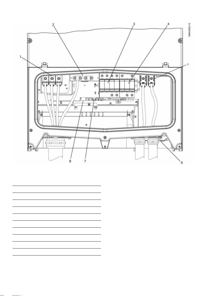
1 Einführung SMA Solar Technology AG
Abbildung 1.5 Überblick über den Installationsbereich
PELV (berührungssicher)
2Geräteerdung
7 Ethernet-Schnittstelle x 2
8 RS-485-Schnittstelle (nicht im Einsatz)
Spannungsführende Teile
1 AC-Anschlussklemmen
5 PV-Anschlussklemmen
Sonstiges
3 AC-Überspannungsschutz (SPDs)
4 DC-Überspannungsschutz (SPDs)
6 PV-Lasttrennschalter
Tabelle 1.2 Überblick über den Installationsbereich
64 STP60-10-IA-xx-10 Installationsanleitung
Page 65

SMA Solar Technology AG 2 Installation
2Installation
2.1Umgebung und Abstände
Abbildung 2.6 Gerade auf vertikaler Oberfläche einbauen. Eine
Rückwärtsneigung von bis zu 10 Grad ist zulässig.
Abbildung 2.1 Ständigen Kontakt mit Wasser vermeiden
Abbildung 2.7 Staub und Ammoniakgase vermeiden
Abbildung 2.2 Direkte Sonneneinstrahlung vermeiden
Abbildung 2.3 Ausreichende Luftströmung sicherstellen
Abbildung 2.4 Ausreichende Luftströmung sicherstellen
Abbildung 2.5 Auf nicht entflammbarer Oberfläche montieren
HINWEIS
Bei der Auswahl des Installationsorts sicherstellen,
dass die Produkt- und Warnhinweise auf dem
Wechselrichter jederzeit sichtbar sind. Ausfürhliche
Informationen finden Sie in Kapitel 5,Seite89.
Installationsanleitung STP60-10-IA-xx-10 65
Page 66

2 Installation SMA Solar Technology AG
2.2Montage der Wandhalterung
Abbildung 2.8 Sicherheitsabstände
HINWEIS
Für eine ausreichende Luftströmung einen
Mindestabstand von 620 mm / 24 in. sicherstellen.
Abbildung 2.9 Wandhalterung
66 STP60-10-IA-xx-10 Installationsanleitung
Page 67

SMA Solar Technology AG 2 Installation
HINWEIS
Die mitgelieferte Wandhalterung muss zwingend
verwendet werden. Wird der Wechselrichter ohne
Wandhalterung einbaut, erlischt der
Garantieanspruch. Es wird dringend empfohlen, alle
6 Montagelöcher zu nutzen.
Montage der Wandhalterung:
• Wandhalterung in der vorgesehenen Umgebung
montieren.
• Schrauben und Dübel verwenden, die das
Wechselrichtergewicht sicher tragen können.
• Sicherstellen, dass die Befestigungsplatte korrekt
ausgerichtet ist.
• Bei der Installation eines oder mehrerer Wechselrichter
die Sicherheitsabstände einhalten, um eine
ausreichende Luftströmung sicherzustellen. Die
Abstände sind in Abbildung 2.8 und auf dem Schild
der Befestigungsplatte angegeben.
• Es wird die Montag e der We chselric hter in einer Rei he
nebeneinander empfohlen. Wenden Sie sich für
Richtlinien zur Montage von Wechselrichtern in
mehreren Reihen übereinander an den Lieferanten.
• An der Frontseite des Wechselrichters zwecks sicherem
Einbau und Servicezugang einen ausreichenden
Abstand einhalten.
2.3Montage des Wechselrichters
Beim Umgang mit dem Wechselrichter lokale
Arbeitsschutzbestimmungen zu Rate ziehen.
Vorgehensweise:
1. Den Wechselrichter anheben. Die Position der
Führungsschlitze an der Seite der Wandhalterung
bestimmen. Verwendung von Bügelschrauben M12 /
1/2" und dazu passende Muttern (nicht im
Lieferumfang enthalten).
Abbildung 2.11 Platzierung des Wechselrichters
Abbildung 2.12 Bügelschrauben
Abbildung 2.10 Montage der Wandhalterung
2. Am Wechselrichter die seitlichen Schrauben in die
Führungsschlitze der Wandhalterung einsetzen.
3. Den Wechselrichter wie abgebildet schieben, damit
die seitlichen Schrauben in die beiden unteren
Führungschlitze und dann in die oberen Schlitze
geführt werden. Siehe Abbildung 2.13 und Abbildung
2.14.
Installationsanleitung STP60-10-IA-xx-10 67
Page 68

2 Installation SMA Solar Technology AG
(&'")3
2.5Zugang zum
Installationsbereich
Schalten Sie vor Beginn der Arbeiten am Wechselrichter
das AC-Netz am Netzschalter und PV über den
eingebauten PV-Lastschalter (DC-Lasttrennschalter) ab.
Stellen Sie sicher, dass das Gerät nicht versehentlich
wiederangeschlossen werden kann. Überprüfen Sie
Mithilfe eines Spannungsprüfers, dass das Gerät
abgeschaltet und spannungsfrei ist. Auch bei
freigeschalteter AC-Netzversorgung und abgeschalteten
Solarmodulen kann der Wechselrichter nach wie vor
Abbildung 2.13 Einführung der Schrauben in die Führungsschlitze
Abbildung 2.14 Einführung der Schrauben in die Führungschlitze –
Detailansicht
4. Darauf achten, dass die vier seitlichen Schrauben
sicher in den Führungsschlitzen der Befestigungsplatte
sitzen.
5. Den Wechselrichter loslassen.
unter gefährlicher Hochspannung stehen. Warten Sie
nach jeder Trennung vom Stromnetz und von den
PV-Modulen mindestens 5 Minuten, bevor Sie fortfahren.
Die Schutzvorschriften bezüglich elektrostatischer
Entladungen beachten. Eventuelle elektrostatische
Ladung vor Handhabung von Elektroteilen durch
Berühren des geerdeten Gehäuses entladen.
Vorgehensweise:
1. Zum Öff nen der Abd eck ung die 3 v ord ere n Sc hra ube n
mit einem TX30-Schraubendreher lösen. Die
Schrauben sind unverlierbare Schrauben und können
nicht herausfallen.
2. Die Abdeckung um 180° anheben. Die Abdeckung
wird durch einen Magneten in der geöffneten Position
gehalten.
3. Zum Schließen der Abdeckung diese wieder nach
unte n zieh en und di e 3 vor dere n Schr auben festz iehen.
2.4Abbau des Wechselrichters
Vorgehensweise:
1. Der Abbau des Wechselrichters erfolgt in umgekehrter
Reihenfolge der Montage.
2. Den Wechselrichter anheben und aus den
Führungsschlitzen der Befestigungsplatte schieben.
3. Den Wechselrichter von der Befestigungsplatte
abheben.
Ab bild ung 2 .15 Vord ere S chr aube n lös en u nd Ab deck ung anhe ben
68 STP60-10-IA-xx-10 Installationsanleitung
Page 69

SMA Solar Technology AG 2 Installation
(&'")3
2.6AC-Netzanschluss
Diese Anweisungen für den Anschluss an das AC-Netz
sind nur für das Fachpersonal bestimmt. Um das Risiko
eines elektrischen Schlages zu verringern, dürfen keine
Wartungsarbeiten ausgeführt werden, die nicht
ausdrücklich in der Bedienungsanleitung beschrieben
sind, außer Sie sind zu deren Ausführung qualifiziert.
Informationen zu Sicherungen und
Fehlerstromschutzeinrichtung (RCD) finden Sie in Kapitel
5,Seite89. Die AC-Sicherung darf die
Strombelastbarkeit der eingesetzten Leiter nicht
überschreiten.
HINWEIS
Alle elektrischen Installationen in den USA und
Kanada müssen gemäß den vor Ort geltenden
elektrischen Normen und dem National Electrical
®
Code
ANSI/NFPA 70 oder dem Canadian
Electrical Code
• Vor dem elektrischen Anschluss des
Wechselrichters an das öffentliche Stromnetz
wend en Sie sich a n Ihr en Net zbetr eiber vo r Ort.
Der elektrische Anschluss des Wechselrichters
darf ausschließlich von Fachkräften
durchgeführt werden.
• Sicherstellen, dass die Kabel für den elektrischen
Anschluss nicht beschädigt sind.
IMI-Erkennung
Der Wechselrichter verfügt über eine(n) eingebaute(n)
Isolationswächter (IMI)/Fehlerstromüberwachungseinheit
(RCMU) gemäß UL 1741 für potenzialbehaftete
netzgebundene PV-Wechselrichter. Er reagiert auch auf
Fehlergleichströme wie auch plötzliche Veränderung im
Erdschlussstrom. Diese Funktion ist bei Normalbetrieb
aktiviert.
Erkennung des Isolationswiderstands
Der Wechselrichter hat eine eingebaute Erkennung des
Isolationswiderstands / ISO Schaltkreis, die gemäß UL
1741 für potentialbehaftete netzgebundene
PV-Wechselrichter zertifiziert ist. Die Erkennung des
Isolationswiderstands führt vor Anschluss an das Stromnetz
eine Messung des Widerstands der angeschlossenen
®
CSA C22.1.durchgeführt werden.
PV-Anlage zur Erde durch. Liegt der Widerstand unterhalb
des Sollwerts gemäß den Netzanschlussregeln, wartet der
Wechselrichter ab und misst den Widerstand nach kurzer
Ze it er neut. Liegt der Wi derst and üb er de m Soll wert g emäß
den Netzanschlussregeln, führt der Wechselrichter einen
Selbsttest durch und wird ans Netz angeschlossen.
Abbildung 2.16 Installationsbereich
Abbildung 2.17 Abisolierung der AC-Kabel
HINWEIS
Für den AC-Anschluss können Kabel mit
mehrdrähtigen, fein- oder feinstdrähtigen Leitern
eingesetzt werden (siehe Abbildung 2.18).
Bei dem Einsatz von Kabeln mit fein- oder
feinstdrähtigen Leitern müssen für den Anschluss
Aderendhülsen verwendet werden.
Installationsanleitung STP60-10-IA-xx-10 69
Page 70

2 Installation SMA Solar Technology AG
Abbildung 2.18 Kabel mit verschiedenen Leitern (von oben nach
unten): eindrähtig, mehrdrähtig, feindrähtig und feinstdrähtig
Der STP 60-Wechselrichter darf nur an ein 3-Phasen-Netz
angeschlossen werden.
Am AC-Kabel alle 4 Drähte abisolieren. Der Schutzleiter
(PE) muss länger als die Netzleiter sein. Siehe Abbildung
2.17.
1. Prüfen, ob die Nennspannung des Wechselrichters der
Netzspannung entspricht.
2. Sicherstellen, dass der Haupttrennschalter geöffnet ist
und durch angemessene Schutzmaßnahmen
sicherstellen, dass ein Wiedereinschalten nicht möglich
ist.
3. Die Frontabdeckung öffnen.
4. Das Kabel durch die AC-Kabelverschraubung zu den
Klemmenleisten schieben.
5. Die drei Netzleiter (L1, L2, L3) und den Schutzleiter
(PE) entsprechend den Markierungen an die
Klemmenleiste anschließen. Der Schutzleiter wird mit
dem in Abbildung 2.19 abgebildeten Symbol
gekennzeichnet.
6. Optional: Einen zusätzlichen PE-Anschluss an den
sekundären PE-Erdungspunkten mit einem externen
Erdungsbolzen des Geräts herstellen, der mit dem
Wechselrichter geliefert wird. Siehe Abbildung 5.2.
7. Alle Drähte müssen ordnungsgemäß mit dem richtigen
Drehmoment befestigt werden. Siehe Kapitel
5.5,Seite94.
Abbildung 2.19 Symbol für Schutzleiter
GEFAHR DURCH ABLEITSTROM
Ableitstrom überschreitet 3,5 mA. Eine unzureichende
Erdung des Wechselrichters kann zu schweren
Verletzungen oder zum Tode führen.
• Stellen Sie sicher, dass die Geräte korrekt durch
einen zertifizierten Elektroinstallateur geerdet
werden.
2.7Kabeleinführung
Optionen für die Kabeleinführung
• Bei STP 60-10: Kabelverschraubungen (vormontiert)
• Bei STP 60-10-US: 2"-Kabelkanaladapter (im
Lieferumfang enthalten)
Bei Austausch des 2"-Kabelkanaladapters sicherstellen,
dass die Schrauben in der in Abbildung 2.19 und
Abbildung 2.20 abgebildeten Reihenfolge angezogen
werden. Zuerst alle Schrauben mit 0,75 Nm und dann mit
2,5 Nm anziehen.
Abbildung 2.20 AC-Montagehalterung
70 STP60-10-IA-xx-10 Installationsanleitung
Page 71

SMA Solar Technology AG 2 Installation
Abbildung 2.21 DC-Montagehalterung
Klemme Bereich
AC+PE 16-95 mm²
PV 16-95 mm²
Tabelle 2.1 Ausreichende Leiterquerschnitte
1)
Beachten Sie immer die Strombelastbarkeit der verwendeten
Kabel.
1)
6-4/0 AWG
6-4/0 AWG
Maximal zulässige
Leitertemperaturen
90 ºC Al/Cu 37-44 mm
90 ºC Al/Cu 14-21 mm
2.8Ethernet-Anschlüsse
Achten Sie beim Einsatz im Außenbereich darauf, ein
geeignetes Kabel zu verwenden. Wenn das Kabel sehr steif
ist, sollte eine Zwischenklemme verwendet werden, um eine
größere Biegsamkeit des Kabels zu erreichen, bevor es an
denWechselrichter angeschlossen wird. Bei einigen Kabel
ist es ggf. ausreichend, die äußere harte Ummantelung an
dem Teil des Kabels zu entfernen, das in das
Wechselrichtergehäuse eingeführt wird. Auf diese Weise
werden die auf den Leiterplatten montierten
RJ-45-Ethernetanschlüsse vor zu starker Beanspruchung
geschützt, die zu Schäden oder Problemen mit der
Verbindung führen könnte.
Vorgehensweise:
1. Den RJ-45-Steckverbinder am Ethernet-Kabel nicht
entfernen.
2. Die Kabel über Kabelverschraubungen durch die
Unterseite des Wechselrichters führen. Siehe
Abbildung 2.22.
3. Einen Einschnitt in die Gummimanschette machen. Die
Manschette in die Verschraubung für eine optimale
Abdichtung einbringen.
4. In den Ethernet-Steckverbinder stecken.
Leitermaterial Durchmesser Kabelmantel mit
mitgelieferter Kabelverschraubung
Abbildung 2.22 Kabelführung durch Kabelverschraubungen
2.9PV-Anschluss
2.9.1Externe
Generatoranschlusskästen
PV-Strings müssen über einen externen
Generatoranschlusskasten an den DC-Eingang
angeschlossen werden. Der Generatoranschlusskasten
verbindet die PV-Strings des PV-Generators und schützt die
einzelnen Strings gegen Überstrom.
HINWEIS
An allen mit dem Generatoranschlusskasten
verbundenen PV-Strings müssen die gleiche Anzahl
an Modulen und der gleiche Modul-Typ
angeschlossen sein. Außerdem müssen alle
angeschlossenen Module die gleiche Ausrichtung
aufweisen.
Installationsanleitung STP60-10-IA-xx-10 71
Page 72

2 Installation SMA Solar Technology AG
HINWEIS
Auf richtige Absicherung achten! Zu Informationen
über korrekte String-Sicherungswerte die
Modul-Handbücher des Herstellers zu Rate ziehen.
Ein geeignetes Voltmeter verwenden, das bis zu 1000 V DC
messen kann. Überprüfen Sie die Polarität und die
Maximalspannung des PV-Generators durch Messen der
PV-Leerlaufspannung. Der Wechselrichter verfügt über
einen Verpolungsschutz, kann aber erst nach korrektem
Anschluss Leistung erzeugen.
Die kombinierte Leistung aus dem
Generatoranschlusskasten muss an den DC-Eingang des
STP 60-Wechselrichters angeschlossen werden.
Abbildung 2.25 DC-Anschlussbereich
Der PV-Generator ist potenzialfrei, wobei beide Leiter (+)
und (-) an die PV-Eingänge des Wechselrichters
angeschlossen sind. Kein Leiter ist geerdet.
Die DC-Leistung kann mit dem im Wechselrichter
eingebauten DC-Lasttrennschalter getrennt werden.
PV darf NICHT mit Erde verbunden werden!
Abbildung 2.24 PV darf nicht mit Erde verbunden werden
HINWEIS
Für den AC-Anschluss können Kabel mit
mehrdrähtigen, fein- oder feinstdrähtigen Leitern
eingesetzt werden (siehe Abbildung 2.26).
Bei dem Einsatz von Kabeln mit fein- oder
feinstdrähtigen Leitern müssen für den Anschluss
Aderendhülsen verwendet werden.
Abbildung 2.26 Kabel mit verschiedenen Leitern (von oben nach
unten): eindrähtig, mehrdrähtig, feindrähtig und feinstdrähtig
1. Den PV-Lasttrennschalter am Wechselrichter oder
Generatoranschlusskasten auf Aus stellen.
2. Die PV-Kabel vom Gerneratoranschlusskasten an den
Wechselrichter anschließen. Die richtige Polarität
sicherstellen, siehe Abbildung 2.27.
3. Alle Drähte müssen ordnungsgemäß mit dem richtigen
Drehmoment befestigt werden. Siehe Kapitel
5.5,Seite94.
72 STP60-10-IA-xx-10 Installationsanleitung
Page 73

SMA Solar Technology AG 3 Ersteinrichtung und Start
3Ersteinrichtung und Start
3.1Benutzerschnittstelle
Die Benutzerschnittstelle besteht aus folgenden Elementen:
• Lokales Display, für alle Wechselrichtervarianten. Das
lokale Display zeigt Statusinformationen des
Wechselrichters. Die Konfiguration oder Einrichtung
des STP 60-Wechselrichters über das Display ist nicht
möglich. Das „#“ im Display erklärt die Betriebsarten.
• Lokales Inbetriebnahme- und Service-Tool (LCS-Tool).
Abbildung 2.27 Anschluss an PV-Eingang
Abbildung 2.28 DC Aufkleber
Schutzklasse der PV-Module
Der Wechselrichter darf nur mit PV-Modulen der
Schutzklasse II nach IEC 61730, Anwendungsklasse A,
betrieben werden.
Schließen Sie nur PV-Module an den Wechselrichter an.
Andere Energiequellen sind nicht zulässig.
PV-Module erzeugen bei Lichteinfall elektrische
Spannung.
2.10Schließen
1. Die Abdeckung des Installationsbereichs des
Wechselrichters schließen. Die 3 vorderen Schrauben
festziehen. Siehe Kapitel 5.5,Seite94.
2. AC zuschalten.
Das LCS-Tool ermöglicht die Konfiguration eines oder
mehrerer STP 60-Wechselrichter.
3.1.1Betriebsarten
Der Wechselrichter hat 5 Betriebsarten, die durch LEDs
angezeigt werden.
Status LEDs LEDs
Vom Netz Grün
Rot
Anschluss erfolgt Grün
Rot
Am Netz Grün
Rot
Internes
Wechselrichterereignis
Ausfallsicher Grün
Tabelle 3.1 Betriebsarten
Vom Netz (Standby) (LEDs aus)
#0-51
Wenn länger als 10 Minuten nicht in das AC-Netz
eingespeist wurde, trennt sich der Wechselrichter
selbstständig vom Netz und schaltet sich ab. Die Benutzerund Kommunikationsschnittstellen werden zu
Kommunikationszwecken weiter mit Strom versorgt.
Grün
Rot
Rot
Installationsanleitung STP60-10-IA-xx-10 73
Page 74

3 Ersteinrichtung und Start SMA Solar Technology AG
Anschlussmodus (Grüne LED blinkt)
#52-53
Der Wechselrichter läuft an, wenn die
PV-Eingangsspannung die DC-Mindesteinspeisespannung
erreicht. Der Wechselrichter führt eine Reihe interner
Selbsttests durch einschließlich einer Messung des
Widerstands zwischen PV-Array und Erde. In der
Zwischenzeit werden auch die Netzparameter überwacht.
Wenn die Netzparameter während des erforderlichen
Zeitraums innerhalb der Spezifikationen liegen (abhängig
vom Grid Code), beginnt der Wechselrichter mit der
Einspeisung in das Stromnetz.
Am Netz (Grüne LED leuchtet)
#60
Der Wechselrichter ist an das AC-Netz angeschlossen und
speist in dieses ein. Der Wechselrichter trennt sich in
folgenden Fällen vom Netz:
• Der Wechselrichter erkennt abnormale
Netzbedingungen (abhängig vom Grid Code).
• ein internes Ereignis tritt auf.
• PV-Leistung ist unzureichend (10 Minuten lang wird
kein Strom eingespeist).
In diesem Fall wechselt der Wechselrichter in den
Anschlussmodus oder in die Betriebsart „Vom Netz
getrennt“.
3.2Display
HINWEIS
Es kann bis zu 10 s dauern, bis das Display nach
dem Einschalten anspricht.
Der Benutzer hat über das integrierte Display auf der
Vorderseite des Wechselrichters Zugang zu Informationen
über das PV-System und den Wechselrichter.
Internes Wechselrichterereignis (Grüne LED blinkt)
#54
Der Wechselrichter wartet auf einen internen Zustand
innerhalb der Grenzwerte (zum Beispiel wegen einer zu
hohen Temperatur), bevor er wieder ans Netz geht.
Ausfallsicher (Rote LED blinkt)
#70
We nn d er W ech sel ric hte r be im S elb stt est (in de r Be tri ebs art
Anschlussmodus) oder während des Betriebs einen
Schaltkreisfehler feststellt, schaltet er in die Betriebsart
„Ausfallsicher“ und wird vom Netz getrennt. Der
Wechselrichter verbleibt in der Betriebsart „Ausfallsicher“,
bis die PV-Leistung zehn Minuten lang ausbleibt oder der
Wechselrichter vollständig abgeschaltet wird (AC+PV).
74 STP60-10-IA-xx-10 Installationsanleitung
Abbildung 3.1 Display mit Steuer- und Funktionstasten
Display mit Steuer- und Funktionstasten
Taste Funktion
F1 Anpassen der Kontraststufe des
F2 Ohne Funktion
F3
F4
Home Zurück zum Hauptfenster
OK Ohne Funktion
Pfeil nach oben Einen Schritt nach oben
Pfeil nach unten Einen Schritt nach unten
Pfeil nach rechts Wechselt zum rechten Bildbereich
Pfeil nach links Wechselt zum linken Bildbereich
Zurück Zurück zum Hauptfenster
Displays. Pfeil-nach-oben/
unten-Taste verwenden, solange
die F1-Taste gedrückt ist.
Page 75

SMA Solar Technology AG 3 Ersteinrichtung und Start
Taste Funktion
On – Grüne LED
Alarm – Rote LED
Tabelle 3.2 Display mit Steuer- und Funktionstasten
Der Bildschirm-Aufbau ist in 3 Abschnitte unterteilt:
1. Hauptbildschirm. Strom und täglicher Ertrag. Dieser
Abschnitt enthält:
– Ist-Ausgangsleistung (kW)
– Ertrag des aktuellen Tags (kWh)
– Gesamtertrag (kWh)
– Aktuelles Datum
–Aktuelle Zeit
– Betriebsart (#)
2. Informationen zum Wechselrichter. Dieser Abschnitt
enthält:
– Gerätetyp des Wechselrichters
– Name des Wechselrichters
– Seriennummer
–IP-Adresse
– MAC-Adresse des SMA Inverter Managers
– Software-Version des Wechselrichters
3. Ist-Werte. Dieser Abschnitt enthält:
– PV-Spannung und Strom
– Spannungen Phase-Phase
–Phasenströme
–Netzfrequenz
3.2.1Ersteinrichtung über LCS-Tool
Das LCS-Tool ermöglicht die Wahl aus einer Liste
vordefinierter Einstellungen für verschiedene Netze. Alle
Netz-spezifischen Grenzwerte müssen über das LCS-Tool
konfiguriert werden.
Nach der Installation alle Kabel prüfen und den
Wechselrichter schließen.
AC zuschalten.
Die korrekte Auswahl des Grid Codes ist wichtig, um die
lokalen und nationalen Standards einzuhalten.
3.2.2PV-Lasttrennschalter einschalten
Abbildung 3.2 PV-Lasttrennschalter
PV-Lasttrennschalter entweder am Wechselrichter oder am
Generatoranschlusskasten einschalten.
3.2.3Inbetriebnahme
Der Wechselrichter startet automatisch, wenn ausreichende
Sonneneinstrahlung zur Verfügung steht. Die
Inbetriebnahme dauert einige Minuten. In dieser Zeit führt
der Wechselrichter eine Selbsttestfunktion durch.
HINWEIS
Der Wechselrichter ist mit Verpolungsschutz
ausgestattet. Der Wechselrichter erzeugt erst
Einspeiseleistung, wenn verdrehte Verpolung
korrigiert wurde.
3.3LCS-Tool
Die STP 60--Wechselrichter und der SMA Inverter Manager
müssen über das lokale Inbetriebnahme- und Service-Tool
(LCS-Tool) in Betrieb genommen werden. Die
Inbetriebnahme ist erforderlich, bevor die
STP 60-Wechselrichter an das AC-Netz angeschlossen
werden und einspeisen.
Das LCS-Tool ist im Downloadbereich unter
www.SMA-Solar.com verfügbar.
Hardware Anforderungen für das LCS-Tool:
•PC mit Windows
•1 GB HDD
• 2 GB RAM
Das LCS-Tool muss auf einem lokalen PC-Laufwerk installiert
werden. Der PC muss über Ethernet an den LAN 1 Port des
SMA Inverter Managers angeschlossen werden.
TM
7 oder neuer
Installationsanleitung STP60-10-IA-xx-10 75
Page 76

3 Ersteinrichtung und Start SMA Solar Technology AG
HINWEIS
Dem LAN 1 Port des SMA Inverter Manager muss
vom DHCP-Server eine IP-Adresse zugewiesen
werden.
Es ist wichtig, dass der PC, auf dem das LCS-Tool
läuft, an das gleiche IP-Subnetz angeschlossen ist wie
der SMA Inverter Manager.
Port LAN 2 ist ausschließlich für
STP 60-Wechselrichter bestimmt.
Abbildung 3.3 Inbetriebnahme von Wechselrichtern über LCS-Tool
1LCS-Tool
2Router/DHCP
3 SMA Inverter Manager
4 Sunny Tripower 60
5LAN 2
6LAN 1
3.3.1Erste Schritte
1. Starten Sie das LCS-Tool. Das To ol zeig t eine L iste aller
identifizierten SMA Inverter Manager. Es kann mehrere
Minuten dauern, bis das LCS-Tool alle SMA Inverter
Manager identifiziert hat.
2. Der Bildschirm zeigt jetzt eine Liste aller SMA Inverter
Manager (siehe Abbildung 3.4). Zum Start des
Assistenten klicken Sie den zu konfigurierenden SMA
Inverter Manager an. Durch Anklicken des SMA
Inverter Manager werden die vom SMA Inverter
Manager gefundenen Wechselrichter angezeigt.
Nicht in Betrieb genommene Wechselrichter (kein
zugewiesener Grid-Code) werden mit einem blauen
Quadrat zusammen mit ihrer Software-Version
aufgeführt.
76 STP60-10-IA-xx-10 Installationsanleitung
Page 77

SMA Solar Technology AG 3 Ersteinrichtung und Start
Abbildung 3.4 LCS-Tool - Startbildschirm
3. Überprüfen, ob Datum und Uhrzeit richtig sind. Falls
nicht, Datum und Uhrzeit einstellen und fortfahren.
Siehe Abbildung 3.5.
Abbildung 3.5 LCS-Tool - Datum und Uhrzeit überprüfen
Installationsanleitung STP60-10-IA-xx-10 77
Page 78

3 Ersteinrichtung und Start SMA Solar Technology AG
4. Eine Liste der durch den ausgewählten SMA Inverter
Manager identifizierten Wechselrichter wird
angezeigt. Siehe Abbildung 3.6.
Prüfen, ob die Liste der Wechselrichter vollständig ist.
Prüfen, ob alle Wechselrichter vorhanden sind. Es ist
möglich, mit der Konfiguration der aufgeführten
Wechselrichter fortzufahren, selbst wenn nicht alle
Wechselrichter gefunden werden. Die unentdeckten
Wechselrichter können später noch konfiguriert werden.
Abbildung 3.6 LCS Tool - Liste der angeschlossenen Wechselrichter
5. Wählen Sie das gewünschte Land aus der Liste der
verfügbaren Optionen für die Wechselrichter im
Netzwerk. Siehe Abbildung 3.7.
6. Wählen Sie den gewünschten Grid-Code aus der Liste
der verfügbaren Optionen für das ausgewählte Land
aus. Im Bedarfsfall einen kundenspezifischen
Grid-Code durch Anklicken der „Load“-Taste laden.
Siehe Abbildung 3.7. Die „Create“-Schaltfläche ist
inaktiv und kann nicht verwendet werden.
78 STP60-10-IA-xx-10 Installationsanleitung
Page 79

SMA Solar Technology AG 3 Ersteinrichtung und Start
Abbildung 3.7 LCS-Tool - Land und Grid-Code auswählen
Abbildung 3.8 LCS-Tool - Überprüfung des Landes und des
Grid-Codes
7. Das LCS-Tool fordert zur Bestätigung des
ausgewählten Landes und des Grid-Codes auf. Siehe
Abbildung 3.8. Eine falsche Konfiguration kann mittels
der Schaltfläche ‚Zurück' und der Änderung der
Einstellungen im vorherigen Fenster geändert werden.
Installationsanleitung STP60-10-IA-xx-10 79
Page 80
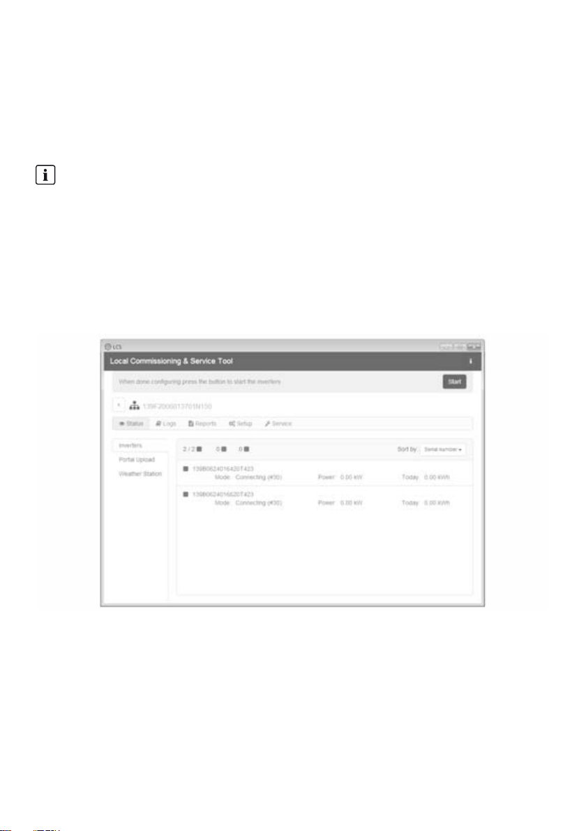
3 Ersteinrichtung und Start SMA Solar Technology AG
8. Das System wendet nun den auf dem SMA Inverter
Manager ausgewählten Grid-Code auf die
gefundenen Wechselrichter an. Jeder zu einem
späteren Zeitpunkt hinzugefügte Wechselrichter
übernimmt automatisch denselben Grid-Code. Pro
SMA Inverter Manager ist nur die Anwendung von
einem Grid-Code möglich.
HINWEIS
Es ist wichtig, den richtigen Grid-Code zu wählen.
Der Grid-Code kann nachträglich ohne Rücksprache
mit SMA Solar Technology AG nicht mehr geändert
werden.
9. Ein grünes Quadrat macht den in Betrieb genommenen
Wechselrichter kenntlich. Die Wechselrichter werden
jedoch erst mit dem Netz verbunden, wenn der
‚Start'-Befehl von der Leiste unterhalb des Startmenüs
erfolgt ist. Siehe Abbildung 3.9.
Abbildung 3.9 LCS Tool - Liste aller an den SMA Inverter Manager
angeschlossenen Wechselrichter
über die Wechselrichtereinstellungen, einschließlich
der eingestellten Trennwerte für die einzelnen
Wechselrichters. Siehe Abbildung 3.10.
10. Wenn genügend PV-Leistung vorhanden ist und die
Grid-Code-Bedingungen erfüllt sind, werden die
Wechselrichter ans Netz angeschlossen.
11. Bei Inbetriebnahme ist es möglich, einen
Inbetriebnahmebericht im Menü „Reports“
herunterzuladen. Der Bericht enthält alle Informationen
80 STP60-10-IA-xx-10 Installationsanleitung
Page 81

SMA Solar Technology AG 3 Ersteinrichtung und Start
Abbildung 3.10 LCS-Tool - Inbetriebnahmebericht
HINWEIS
Wenn der gewünschte Grid-Code nicht verfügbar ist
oder das LCS-Tool eine Warnung wegen
inkompatibler Softwareversionen anzeigt, müssen
der Grid-Code und die Softwarebibliothek auf dem
LCS-Tool aktualisiert werden.
Es ist möglich kundenspezifische Grid Code-Dateien
mit angepassten Einstellwerten zu erstellen. Nehmen
Sie hierzu Kontakt mit SMA Solar Technology AG
auf.
Installationsanleitung STP60-10-IA-xx-10 81
Page 82

4 Service SMA Solar Technology AG
4Service
4.1Fehlersuche und -behebung
Die Informationen werden in Tabellen aufgelistet und
zeigen die Meldungen an, die im LCS-Tool erscheinen und
als Ereignisse bekannt sind. Die Tabellen enthalten
Be sch rei bun gen von Ereig nis sen sow ie E rkl äru nge n, w elche
Maßnahmen im Falle von Ereignissen zu ergreifen sind.
Ereignistyp Zeigt an, ob das Ereignis der Kategorie Netz, PV, Intern oder Ausfallsicher zuzurechnen ist.
ID Die spezifische Ereignis-ID.
Display Im Display angezeigter Text.
Beschreibung Beschreibung des Ereignisses.
Maßnahme Beschreibung der zu ergreifenden Maßnahme, bevor Dritte involviert werden.
VNB Wenn die Fehlfunktion nicht durch die empfohlene Maßnahme identifiziert werden konnte,
Hotline Wenn die Fehlfunktion durch die empfohlene Maßnahme nicht identifiziert werden konnte,
PV Wenn die Fehlfunktion durch die empfohlene Maßnahme nicht identifiziert werden konnte,
Netzbezogene Ereignisse
wenden Sie sich an den VNB.
wenden Sie sich an den Service (siehe Kapitel6 „Kontakt“,Seite97).
wenden Sie sich an den PV-Lieferanten.
ID Statusmel
dung
1–6 Netzspannung zu niedrig. Spannung und AC-Installation
7–9 Durchschnittliche
10–15 Netzspannung zu hoch. Spannung und AC-Installation
16–18 Der Wechselrichter hat eine
19, 22 Netzfrequenz zu niedrig oder
82 STP60-10-IA-xx-10 Installationsanleitung
Beschreibung Maßnahme VNB Hotline PV
x- überprüfen. Ist die Spannung gleich
Null, prüfen Sie die Sicherungen.
Netzspannung 10 Minuten
lang zu hoch.
Spannungsspitze im Netz
gemessen.
zu hoch.
Prüfen, ob die Installation
entsprechend der
Installationsanleitung durchgeführt
wurde. Fordern Sie in diesem Fall
eine neue Grid-Code-Datei mit
erhöhter Spannungsgrenze oder
Blindleistung zur
Spannungsunterdrückung an.
überprüfen.
Spannung und AC-Installation
überprüfen.
Netzfrequenz überprüfen. x - -
x- -
x- -
x- -
Page 83

SMA Solar Technology AG 4 Service
ID Statusmel
Beschreibung Maßnahme VNB Hotline PV
dung
31–33 Gleichstromanteil im AC-Netz
zu hoch.
Bei wiederholten täglichen
Vorfällen eine Vor-Ort-Netzanalyse
durchführen.
34–37 FI-Überwachungsgerät
(RCMU) hat Überstrom
gemessen.
DC- und AC-Versorgung abschalten
und warten, bis sich das Display
ausschaltet. Anschließend DC- und
AC-Versorgung einschalten und
prüfen, ob das Ereignis erneut
eintritt. Sichtprüfung sämtlicher
PV-Kabel und -Module durchführen.
40 AC-Netz
nicht
konform
AC-Netz liegt länger als zehn
Minuten außerhalb des
zulässigen Bereichs (Frequenz
Netzfrequenz, Netzspannung,
Softwareversion und
Grid-Code-Einstellung prüfen.
und/oder Spannung).
41–43 Fault Ride Through. Der
Wechselrichter hat festgestellt,
dass die Netzspannung unter
Wenn dieses Ereignis mehrmals
täglich eintritt, führen Sie eine
Vor-Ort-Netzanalyse durch.
oder über einem bestimmten
Niveau liegt.
48, 51 Netzfrequenz zu niedrig oder
zu hoch.
54–56 Gleichstromanteil im AC-Netz
zu hoch (Stufe 2).
Netzfrequenz und AC-Installation
prüfen.
Bei wiederholten täglichen
Vorfällen eine Vor-Ort-Netzanalyse
durchführen.
61 Netzausfall, offene Phase
erkannt.
Den zuständigen Netzbetreiber
kontaktieren, wenn das Ereignis
mehrmals innerhalb eines Tages
auftritt.
62 Netzausfall. Den zuständigen Netzbetreiber
kontaktieren, wenn das Ereignis
mehrmals innerhalb eines Tages
auftritt.
64-81 Netzspannung an Phase zu
niedrig.
Spannung und AC-Installation
überprüfen. Ist die Spannung gleich
Null, prüfen Sie die Sicherungen.
Tabelle 4.1 Netzbezogene Ereignisse
-x -
-x -
x- -
x- -
x- -
x- -
x- -
x- -
Installationsanleitung STP60-10-IA-xx-10 83
Page 84

4 Service SMA Solar Technology AG
PV-bezogene Ereignisse
ID Statusmel
103 Der
115,
260
258 PV-Spannun
278 DC-Spannung ausdrückliche
Tabelle 4.2 PV-bezogene Ereignisse
dung
PV-Strom ist
zu hoch/
wartend
PV ISO zu
niedrig
g zu hoch/
wartend
Beschreibung Maßnahme VNB Hotline PV
Zu viele PV-Module sind
parallel geschaltet. Dies sollte
nur bei neu installierten
Systemen angezeigt werden.
Der Widerstand zwischen den
PV-Strings und der Erde (PE) ist
für die Inbetriebnahme des
Wechselrichters zu niedrig.
Nach 10 Minuten führt der
Wechselrichter automatisch
eine neue Messung durch.
DC-Spannung ist zu hoch. Prüfen, ob die PV-Installation und
Warnung.
Systembezogene Ereignisse
ID Statusmel
dung
2000 Kommunikationsbaugruppe
2010,
2011
2012 2018
2030 Die Übermittlung des Grid
2050,
2051
Beschreibung Maßnahme VNB Hotline PV
fährt hoch.
Das Software-Update des
Hauptrechners wurde gestartet
/ ist beendet.
Das Software-Update ist
fehlgeschlagen.
Godes an den Hauptrechner
ist fehlgeschlagen.
Ethernet-Verbindung ist aktiv /
getrennt.
Anzahl der parallel geschalteten
Strings und Stromnennwerte prüfen.
Wurde der Stromgrenzwert
überschritten? Strings wieder
parallel schalten
Sämtliche PV-Kabel und -Module
per Sichtprüfung auf korrekte
Installation gemäß
Installationsanleitung prüfen. Das
Ereignis deutet möglicherweise
darauf hin, dass der PE-Anschluss
fehlt.
die -Auslegung den Empfehlungen
in den Handbüchern entsprechen.
Prüfen, ob die PV-Installation und
die -Auslegung den Empfehlungen
in den Handbüchern entsprechen.
----
----
Software-Update erneut beginnen.
Falls Fehler beim Update auftreten,
kontaktieren Sie den Service.
Wenn dieses Ereignis öfter auftrit,
kontaktieren Sie den Service.
Keine Maßnahme
notwendig.Dieser Fehler dient
beispielsweise dazu, schlechte
Ethernet-Kabel zu identifzieren.
-x x
-x x
-x x
-x x
-x -
-x -
-- -
84 STP60-10-IA-xx-10 Installationsanleitung
Page 85

SMA Solar Technology AG 4 Service
ID Statusmel
Beschreibung Maßnahme VNB Hotline PV
dung
2052,
2053
Die Übermittlung des Grid
Codes vom SMA Inverter
Manager zum STP 60-10
wurde gestartet / beendet.
2054 Die Übermittlung des Grid
Godes vom SMA Inverter
Manager zum STP 60-10 ist
fehlgeschlagen.
Tabelle 4.3 Systembezogene Ereignisse
Interne Ereignisse
ID Statusmel
dung
201–
208
209,
210
211 Lüfterdrehz
ahl niedrig
213–
215
216–
218
219–
221
225–
240,
275
241,
242,
245,
249
Beschreibung Maßnahme VNB Hotline PV
Die Innentemperatur des
Wechselrichters ist zu hoch.
Zu hohe Spannung im
DC-Zwischenkreis.
Die Lüfterdrehzahl ist zu
niedrig.
Interner Fehler. Gemessene
Spannung vor und hinter dem
Relais weicht zu sehr ab.
Zu hoher gemessener Strom
auf der AC-Seite.
Interner Fehler. Gemessene
Spannung vor und hinter dem
Relais weicht zu sehr ab.
Störung im Speicher/
EEPROM.
Interner Kommunikationsfehler. Wechselrichter neu starten. Wenn
----
Wenn dieses Ereignis öfter auftrit,
-- -
kontaktieren Sie den Service.
Überprüfen Sie, dass keine
-x Gegenstände oder Staub auf dem
We chs elr ich ter lie gt u nd p rüf en S ie,
ob die Lüftungskanäle frei und nicht
verstopft sind.
Wenn das Ereignis andauert, den
-x Wechselrichter durch Trennung der
DC- und AC-Versorgung
zurücksetzten. Wenn sich das
Ereignis wiederholt, über das
Display prüfen, ob die
PV-Spannung den Höchstwert
überschreitet.
Prüfen, ob der Lüfter des
-x Wechselrichters blockiert ist.
Den Service kontaktieren. - x -
Den Service kontaktieren. - x -
Den Service kontaktieren. - x -
Wechselrichter neu starten. Wenn
-x das Ereignis andauert, den Service
kontaktieren.
-x das Ereignis andauert, den Service
kontaktieren.
Installationsanleitung STP60-10-IA-xx-10 85
Page 86

4 Service SMA Solar Technology AG
ID Statusmel
Beschreibung Maßnahme VNB Hotline PV
dung
248 Interner CPU-Fehler. Wechselrichter neu starten. Wenn
das Ereignis andauert, den Service
kontaktieren.
252–
254
243,
263
Zu hoher gemessener Strom
auf der AC-Seite.
Wenn sich das Ereignis wiederholt,
den Service kontaktieren.
Interner Fehler. Wechselrichter neu starten. Wenn
das Ereignis andauert, den Service
kontaktieren.
279 Fehler des Temperaturfühlers Wenn das Ereignis andauert, den
Service kontaktieren.
280 Selbsttest 24-Stunden-Timeout
Keine. - - -
Der Selbsttest muss mindestens
einmal in 24 Stunden laufen.
281 Zu viele RCMU-Ereignisse in
den letzten 24 Stunden.
Innerhalb von 24 Stunden sind
nach einem Ereignis 34 nur 4
Bis zu 24 Stunden warten. Wenn
das Ereignis 34 wieder auftritt, die
Maßnahme für Ereignis 34
befolgen.
automatische
Wiederzuschaltversuche
zulässig. Der Wechselrichter
versucht automatisch die
Wiederzuschaltung nach
einem bestimmten Zeitraum.
282 Grid-Code-Einstellungen
ungültig.
Wechselrichter neu starten. Wenn
der Fehler weiterhin auftritt, bitten
Sie die Serviceabteilung um die
Erstellung einer neuen
Grid-Code-Datei bzw. die erneute
Auswahl eines
Standard-Grid-Codes.
283 Gatedrive-Fehler. Wechselrichter neu starten. Wenn
das Ereignis andauert, den Service
kontaktieren.
323 Fehler des internen Lüfters.
Maximale Ausgangsleistung
Wenn sich das Ereignis wiederholt,
den Service kontaktieren.
wurde reduziert.
Tabelle 4.4 Interne Ereignisse
-x -
-x -
-x -
-x -
-x -
-x -
-x -
-x -
86 STP60-10-IA-xx-10 Installationsanleitung
Page 87

SMA Solar Technology AG 4 Service
Durch den Selbsttest erzeugte Ereignisse
ID Beschreibung Maßnahme VNB Hotline PV
100 PV-Eingangsstrom ist negativ.
Sensorfehler.
Polarität der PV-Anlage prüfen, wenn
diese korrekt ist, mit dem Service in
Verbindung setzen.
264,
266
Messkreistest fehlgeschlagen. Wechselrichter neu starten. Wenn das
Ereignis andauert, den Service
kontaktieren.
272 PV-Überspannungsschutzgerät-Fehler.
Wechselrichter läuft weiter ohne
Überspannungsschutz.
273 AC-Netz-Überspannungsschutzgerät-Fe
hler. Wechselrichter läuft weiter ohne
Überspannungsschutz.
274 Status des Überspannungsschutzgerätes
unbekannt.
PV-Überspannungsschutzgerät
aust ausch en. De tails entne hmen Sie den
Anweisungen zum SPD-Austausch.
PV-Überspannungsschutzgerät
aust ausch en. De tails entne hmen Sie den
Anweisungen zum SPD-Austausch.
Wechselrichter neu starten. Wenn das
Ereignis andauert, den Service
kontaktieren.
350–
352
Selbsttest der
Fehlerstromüberwachungseinheit
Den Service kontaktieren. - x -
(RCMU) fehlgeschlagen.
353 Stromsensortest fehlgeschlagen. Den Service kontaktieren. - x 356–
361
Transistor- und Relais-Test
fehlgeschlagen, oder
Den Service kontaktieren. - x -
Wechselrichterrelais defekt (Kontakt
vermutlich geschweißt).
366 Selbsttest der
Den Service kontaktieren. - x Fehlerstromüberwachungseinheit
(RCMU) fehlgeschlagen.
Tabelle 4.5 Durch den Selbsttest erzeugte Ereignisse
-x -
-x -
-x -
-x -
-x -
Installationsanleitung STP60-10-IA-xx-10 87
Page 88
4 Service SMA Solar Technology AG
4.2Wartung
Sicherstellen, dass der Kühlkörper an der Rückseite des
Wechselrichters nicht verdeckt wird.
Die Kontakte des PV-Trennschalters einmal pro Jahr
reinigen. Zum Reinigen den Schalter zehnmal ein- und
ausschalten. Der PV-Trennschalter befindet sich an der
Unterseite des Wechselrichters.
Für korrekten Betrieb und eine lange Lebensdauer an
folgenden Stellen freie Luftzirkulation sicherstellen:
• rund um den Kühlkörper oben und seitlich am
Wechselrichter (dort tritt die Luft aus) und
• zum Lüfter an der Unterseite des Wechselrichters hin.
Um Verstopfungen zu entfernen, mit Druckluft, einem
weichen Tuch oder einer Bürste reinigen.
Die Temperatur des Kühlkörpers kann 70 °C
überschreiten.
88 STP60-10-IA-xx-10 Installationsanleitung
Page 89

SMA Solar Technology AG 5 Technische Daten
5Technische Daten
5.1Spezifikationen
Parameter STP 60-10
AC
Nenn-Scheinleistung
Nenn-Wirkleistung
Blindleistungsbereich
AC Nennspannung (Spannungsbereich) 3P + PE (WYE) / 400-480 V (+/- 10 %)
Unterstützte Erdungssysteme TT, TN
Nennstrom AC 3 x 87 A
Max. Strom AC 3 x 87 A (3 x 72 A @ 480 V)
AC-Klirrfaktor (THD, bei Ausgangsnennleistung) < 1%
Einschaltstrom 9,2 A/5 ms
Maximaler Ausgangsfehlerstrom Effektivwert 49,8 A über 3 Perioden
Leistungsfaktor - Standard > 0,99 bei Nennleistung
Verschiebungsfaktor - geregelt 0,8 übererregt bis 0,8 untererregt
Stromverbrauch im Standby-Modus (für die
Kommunikation)
Nenn-Netzfrequenz (Bereich) 50/60 Hz (+/- 10 %)
DC
Eingangsspannungsbereich 565 … 1000 V bei 400 Vac
Nennspannung DC 630 V bei 400 Vac
MPPT-Spannungsbereich – Nennleistung 570 … 800 V bei 400 Vac
Max. Gleichspannung 1000 V
Mind.-Leistung am Netz 100 W
Max. MPPT Strom DC4) 110 A
Max. Kurzschlussstrom DC4) 150 A
MPP-Tracker/Eingang pro MPPT 1 / 1 (für die Verwendung eines externen
Überspannungskategorien AC: Überspannungskategorie III (OVC III),
Wirkungsgrad
Max. EU/CEC-Wirkungsgrad 98,8 %
1)
2)
1)
680 … 1000 V bei 480 Vac
685 … 800 V bei 480 Vac
Generatoranschlusskastens)
PV: Überspannungskategorie II (OVC II)
60 kVA
60 kW
0-60 kVAr
3 W
710 V bei 480 Vac
Installationsanleitung STP60-10-IA-xx-10 89
Page 90

5 Technische Daten SMA Solar Technology AG
Parameter STP 60-10
EU-Wirkungsgrad bei 630V
dc
CEC-Wirkungsgrad bei 400/480 V
ac
98,3 %
98,0 %/98,5 %
MPPT Wirkungsgrad, statisch 99,9 %
Gehäuse
Abmessungen (H x B x T) 740 × 570 × 300 mm (29 × 22,5 × 12")
Gewicht 75 kg (165 lbs)3)
Geräuschbelastung 58 dB(A) (typisch)
Tabelle 5.1 Spezifikationen
1)
Bei Nenn-Netzspannung.
2)
Bei Nenn-Netzspannung, Cos(phi) = 1.
3)
Je nach installierten Optionen.
4)
Unter allen Bedingungen.
Parameter STP 60-Serie
Schutzklasse I
Elektrisch
Elektrische Sicherheit • IEC 62109-1/IEC 62109-2 (Klasse I, geerdet –
Kommunikation Teil Klasse II, PELV)
• UL 1741 für potenzialbehaftete netzgebundene
PV-Wechselrichter
• IEEE 1547
Funktional
Funktionale Sicherheit • Spannungs- und Frequenzüberwachung
• Überwachung des Gleichstromanteils im
Wechselstrom
• Überwachung des Isolationswiderstands
• FI-Überwachung
• UL1998
Inselbetriebserkennung – Netzausfall • Aktive Frequenzverschiebung
• Trennung
• Dreiphasenüberwachung
•ROCOF/SFS
RCD-Kompatibilität
Tabelle 5.1 Sicherheitsspezifikationen
1)
Je nach regionalen Vorschriften.
1)
Typ B, 600 mA
90 STP60-10-IA-xx-10 Installationsanleitung
Page 91

SMA Solar Technology AG 5 Technische Daten
5.2Abschalteinstellungen
Abbildung 5.1 Überspannung und Unterspannung Trennung
Nenngröße Netz Umin2
Nenn-Spannung:
400 V
Nenn-Spannung:
480 V
Tabelle 5.3 Standards Spannung Abschalteinstellungen und
Abschaltzeiten
Standard 200,00 0,16 352,00 2,00 440,00 1,00 480,00 0,16
Bereich 160-240 0.1-3.0 300-380 0.5-3.0 420-480 0.5-3.0 440-520 0.1-3.0
Standard 240,00 0,16 423,00 2,00 528,00 1,00 576,00 0,16
Bereich 192-288 0.1-3.0 360-456 0.5-3.0 504-576 0.5-3.0 528-624 0.1-3.0
Fmin2
[Hz]
[V]
T_Fmin2
[s]
T_Umin2
[s]
Fmin1
[Hz]
Umin1
[V]
T_Fmin1
[s]
T_Umin1
[s]
Fmax1
[Hz]
Umax1
[V]
T_Umax1
[s]
T_Fmax1
[s]
Umax2
[V]
Fmax2
[Hz]
T_Umax2
[s]
T_Fmax2
[s]
Standard 57,00 0,16 59,30 10,00 60,50 0,16 - Bereich 56.5-57.5 0.1-3.0 57.0-59.8 0,16-300 60.1-60.9 0.16-3.0 60.1-61.0 0.1-3.0
Tabelle 5.4 Standard Frequenz Abschalteinstellungen und
Abschaltzeiten
HINWEIS
Die Werte gelten nur für IEEE 1547.
Installationsanleitung STP60-10-IA-xx-10 91
Page 92

5 Technische Daten SMA Solar Technology AG
5.3Konformität
Internationale Normen STP 60-Serie
Wirkungsgrad EU-Wirkungsgrad, Standard: EN 50530
CEC-Wirkungsgrad, Standard: CEC-Richtlinie
Testverfahren: Leistungstestprotokoll für die Bewertung von
Wechselrichtern, die in netzgekoppelten Photovoltaikanlagen eingesetzt
EC-Niederspannungsrichtlinie 2006/95/EC
EC-Richtlinie zur elektromagnetischen
Verträglichkeit (EMV)
Sicherheit IEC 62109-1/IEC 62109-2
Funktionale Sicherheit IEC 62109-2
EMV, Störfestigkeit EN 61000-6-1
EMV, Störaussendung EN 61000-6-3
Oberschwingungsströme EN 61000-3-12
CE Ja
Eigenschaften des Versorgungsnetzes IEC 61727
Tabelle 5.5 Konformität mit internationalen Normen
werden (Entwurf): 1. März 2005
2004/108/EC
UL 1741
UL 508i
UL 1741/IEEE 1547
EN 61000-6-2
EN 61000-6-4
CISPR 11 Klasse B
FCC Teil 15
EN 50160
IEEE 1547 UI
Zulassungen und Zertifikate sind im Downloadbereich unter
www.SMA-Solar.com verfügbar.
92 STP60-10-IA-xx-10 Installationsanleitung
Page 93

SMA Solar Technology AG 5 Technische Daten
5.4Installationsbedingungen
Parameter Spezifikation
Betriebstemperaturbereich -25 °C … 60 °C (mögliche Leistungsreduzierung über
45 °C) (-13 °F … 140 °F) (mögliche Leistungsreduzierung
über 113 °F)
Lagertemperatur -40 °C … 60 °C
Relative Luftfeuchtigkeit 95 % (nicht kondensierend)
Verschmutzungsgrad PD2
Umweltkategorie IEC62109-1 Außenbereich, nass (Details siehe Kapitel 2,Seite65)
Umgebungsklassifizierung gemäß IEC 60721-3-4 4K4H/4Z4/4B2/4S3/4M2/4C2
Kühlkonzept Zwangskühlung
Luftqualität – Allgemein ISA S71.04-1985
Klasse G3 (bei 75 % rF)
Luftqualität – an der Küste, in Industriegebieten und
landwirtschaftlichen Regionen
Vibrationen < 1G
Gehäuseschutzklasse IP65
UL 50E Gehäuse-Typ NEMA 3R
Max. Betriebshöhe über NHN (Normalhöhennull) 2000 m (6500 Fuß) über dem Meeresspiegel (ab einer
Installation Ständigen Kontakt mit Wasser vermeiden.
* Aufstellung in Höhen > 2000 m sind auf Anfrage möglich, hierzu SMA Solar Technology AG kontaktieren.
Tabelle 5.6 Installationsbedingungen
Muss gemäß ISA S71.04-1985 gemessen und eingestuft
werden: G3 (bei 75 % rF)
Höhe von 1000 m kann es zu einer Leistungsreduzierung
kommen).*
Direkte Sonneneinstrahlung vermeiden.
Ausreichende Luftströmung sicherstellen.
Auf nicht entflammbarer Oberfläche montieren.
Gerade auf vertikaler Oberfläche einbauen.
Staub und Ammoniakgase vermeiden.
Installationsanleitung STP60-10-IA-xx-10 93
Page 94

5 Technische Daten SMA Solar Technology AG
5.5Drehmomentspezifikationen
Wenn die Blindverschlüsse entfernt werden (siehe (7) in
Abbildung 5.2), sind Anschlüsse der Typen: 3, 3S, 4, 4X,
6, 6P zu verwenden.
5.6Spezifikation für die
Netzsicherungen
Parameter Spezifikation
87 A
100-125 A
125 A
125 A
Abbildung 5.2 Überblick über Wechselrichter mit
Drehmomentvorgaben
Parameter Werkzeug Anzugsdreh-
1M63-Kabelverschr
aubung
2 Klemmen am
AC-Anschluss
3 Primärer
Schutzleiter
(sekundärer
Schutzleiter direkt
rechts davon)
4 Klemmen am
DC-Anschluss
5M32-Kabelverschr
aubung
6 Überwurfmutter für
M32-Kabelverschr
aubung
7M25-Kabelverschr
aubung
8 Überwurfmutter für
M25-Kabelverschr
aubung
9 M6 Geräte-Erdung
(Potentialausgleich
sklemme)
Vordere
Schrauben (nicht
abgebildet)
Schraubenschlüsse
l 65/68 mm
TX 30 14 Nm
TX 30 3,9 Nm
TX 30 14 Nm
Schraubenschlüsse
l, 36 mm
Schraubenschlüsse
l, 36 mm
Schraubenschlüsse
l 33 mm
Schraubenschlüsse
l 33 mm
TX 20 3,9 Nm
TX 30 1,5 Nm
moment
6 Nm (53 in-lbf)
(124 in-lbf)
(35 in-lbf)
(124 in-lbf)
6 Nm (53 in-lbf)
1,8 Nm
(16 in-lbf)
10 Nm
(89 in-lbf)
1,8 Nm
(16 in-lbf)
(35 in-lbf)
(13 in-lbf)
Maximaler Wechselrichterstrom, I
Empfohlener Typ der trägen Sicherung gL/gG
(IEC 60269-1)
Empfohlener Typ der trägen Sicherung Klasse
T (UL/USA)
Empfohlener Leitungsschutzschalter (MCB) Typ
B oder C
Maximale Sicherungsgröße 125 A
Tabelle 5.8 Spezifikation für die Netzsicherungen
acmax
HINWEIS
Örtliche Vorschriften beachten.
Tabelle 5.7 Anzugsdrehmomente
94 STP60-10-IA-xx-10 Installationsanleitung
Page 95

SMA Solar Technology AG 5 Technische Daten
5.7Technische Daten der
Kommunikationsschnittstellen
Schnittstelle Parameter Parameterdetails Spezifikation
Ethernet Kabel Durchmesser Kabelmantel ( ⌀ ) 2 x 5-7 mm
Kabeltyp STP-Kabel (Shielded Twisted Pair,
Wellenwiderstand (Impedanz)
der Kabel
RJ-45-Steckverbinder: 2 Stck.
Drahtstärke 24–26 AWG (je nach Ausführung
RJ-45 für Ethernet
Kabelschirmabschluss Über RJ-45-Stecker
Galvanische
Schnittstellentrennung
Direkter Berührungsschutz Doppelte/verstärkte Isolierung Ja
Kurzschlussschutz Ja
Kommunikation Netzwerktopologie Sternverbindung und verkettete
Kabel Max. Kabellänge zwischen
Wechselrichtern
Max. Anzahl der
Pro SMA Inverter Manager 42
Wechselrichter
Tabelle 5.9 Technische Daten der Kommunikationsschnittstellen
1)
Achten Sie beim Einsatz im Außenbereich darauf, ein geeignetes
Kabel zu verwenden. Wenn das Kabel sehr steif ist, sollte
eine Zwischenklemme verwendet werden, um eine größere
Biegsamkeit des Kabels zu erreichen, bevor es an den
Wechselrichter angeschlossen wird. Bei einigen Kabel ist es
ggf. ausreichend, die äußere harte Ummantelung an dem
Teil des Kabels zu entfernen, das in das
Wechselrichtergehäuse eingeführt wird. Auf diese Weise
werden die auf den Leiterplatten montierten
RJ-45-Ethernetanschlüsse vor zu starker Beanspruchung
geschützt, die zu Schäden oder Problemen mit der
Verbindung führen könnte.
CAT 5e oder SFTP CAT 5e)
100 Ω – 120 Ω
des RJ-45-Steckers)
Ja, 500 Veff
Verbindung
100 m (328 ft)
1)
Abbildung 5.3 Hilfsschnittstellen (Ausschnitt der
Kommunikationsleiterplatte mit RJ-45-Ethernet-Anschlüssen)
Installationsanleitung STP60-10-IA-xx-10 95
Page 96

5 Technische Daten SMA Solar Technology AG
5.8Ethernet-Anschlüsse
Abbildung 5.4 Pinbelegung des RJ-45-Steckers für Ethernet
Pinbelegung
Ethernet
1. RX+ Grün/Weiß Orange/Weiß
2. RX Grün Orange
3. TX+ Orange/Weiß Grün/Weiß
4. Blau Blau
5. Blau/Weiß Blau/Weiß
6. TX- Orange6, Grün
7. Braun/Weiß Braun/Weiß
8. Braun Braun
Farbstandard
Cat. 5
T-568A
Cat. 5
T-568B
5.8.1Netzwerktopologie
Der Wechselrichter verfügt über zwei
Ethernet-RJ-45-Buchsen, die den Anschluss mehrerer
Wechselrichter in einer Linientopologie ermöglichen (als
Alternative zur üblichen Sterntopologie).
HINWEIS
Ringtopologie (C in Abbildung 5.5) ist nur zulässig,
wenn sie mit einem Ethernet-Switch realisiert wird, der
das Spanning-Tree-Protokoll unterstützt.
Abbildung 5.5 Netzwerktopologie
A Lineare Verkettung
B Sterntopologie
C Ringtopologie (nur bei Einsatz des
Spanning-Tree-Protokolls)
1 Sunny Tripower 60
2 Ethernet-Switch
Status der LEDs neben der Ethernet-Schnittstelle ist in Tabelle
5.12 erklärt. Pro Schnittstelle gibt es 2 LEDs.
Status Gelbe LED Grüne LED
Off 10 MBit/s
Verbindungsgeschwindigkeit
On 100 MBit
Verbindungsgeschwindigkeit
Blinkt - Aktivität
Tabelle 5.12 LED-Status
Kein Link
Link
96 STP60-10-IA-xx-10 Installationsanleitung
Page 97

SMA Solar Technology AG 6 Kontakt
6Kontakt
Bei technischen Problemen mit unseren Produkten wenden
Sie sich an die SMA Service Line. Wir benötigen folgende
Daten, um Ihnen geziehlt helfen zu können:
• Gerätetyp des Wechselrichters
• Seriennummer des Wechselrichters
• Firmware-Version des Wechselrichters
• Ggf. länderspezifische Sondereinstellungen des
Wechselrichters
• Typ und Anzahl der angeschlossenen PV-Module
• Montageort und Montagehöhe des Wechselrichters
• Display-Meldung
Installationsanleitung STP60-10-IA-xx-10 97
Page 98

6 Kontakt SMA Solar Technology AG
98 STP60-10-IA-xx-10 Installationsanleitung
Page 99

SMA Solar Technology AG
Disposiciones legales
Las informaciones contenidas en esta documentación
son propiedad de SMA Solar Technology AG. La
publicación, completa o parcial, requiere el
consentimiento por escrito de SMA Solar Technology
AG. La reproducción interna por parte de una
empresa con vistas a evaluar el producto o
emplearlo correctamente está permitida y no
requiere autorización.
Garantía de SMA
Las condiciones actuales de garantía pueden
descargarse en la página www.SMA-Solar.com.
Marcas registradas
Se rec onocen t odas las mar cas re gis tra das , inclus o si
no están señaladas por separado. La falta de
señalización no implica que la mercancía o las
marcas sean libres.
La marca y los logotipos de BLUETOOTH® son
marca s registradas d e Bluetooth SIG , INC. T odo uso
que se haga de estas marcas a través de SMA Solar
Technology AG se realiza con licencia.
Modbus® es una marca registrada de Schneider
Electric y cuenta con licencia de la Modbus
Organization, Inc.
QR Code es una marca registrada de DENSO
WAVE INCORPORATED.
Phillips® y Pozidriv® son marcas registradas de
Phillips Screw Company.
®
Torx
es una marca registrada de Acument Global
Technologies, Inc.
SMA Solar Technology AG
Sonnenallee 1
34266 Niestetal
Alemania
Tel. +49 561 9522-0
Fax +49 561 9522-100
www.SMA.de
Correo electrónico: info@SMA.de
© 2004 - 2015 SMA Solar Technology AG.
Reservados todos los derechos.
Instrucciones de instalación STP60-10-IA-xx-10 99
Page 100
SMA Solar Technology AG
1&-*(30
INDICACIONES IMPORTANTES
PARA LA SEGURIDAD
En este documento se utiliza estos símbolos:
Símbolo Explicación
1&-*(30
"%7&35&/$*"
"5&/$*/
13&$"6$*/
☐
☑ Resultado deseado
✖Posible problema
Seguridad general
Advertencia que, de no ser observada, causa la muerte o lesiones físicas graves
Advertencia que, de no ser observada, puede causar la muerte o lesiones físicas graves
Advertencia que, de no ser observada, puede causar lesiones físicas leves o de
gravedad media
Advertencia que, de no ser observada, puede causar daños materiales
Indicación de que el apartado siguiente recoge actividades que deben llevar a cabo
únicamente especialistas
Información importante para un tema u objetivo concretos, aunque no relevante para la
seguridad
Requisito necesario para alcanzar un objetivo determinado
"5&/$*/
Este documento contiene instrucciones importantes de
obligado cumplimiento durante la instalación y el
mantenimiento del inversor.
Antes de la instalación
Compruebe que no se hayan producido daños en el
equi po ni e n el emba laje. En ca so de d uda, p óngas e
en contacto con el proveedor antes de comenzar la
instalación.
"%7&35&/$*"
Instalación
Para conseguir unas condiciones de seguridad óptimas,
siga los pasos que se describen en este documento.
Recuerde que el inversor tiene dos lados con tensión: la
entrada fotovoltaica y la red de CA.
100 STP60-10-IA-xx-10 Instrucciones de instalación
Desconexión del inversor
Antes de comenzar a trabajar con el inversor, desconecte
la CA en el interruptor de red eléctrica y el fotovoltaico
girando el interruptor-seccionador fotovoltaico.
Asegúrese de que no se puede volver a conectar el
inversor de manera involuntaria. Utilice un detector
capacitivo para asegurarse de que la unidad está
desconectada y sin tensión. Aunque esté desconectado
de la red de CA y los módulos, el inversor puede estar
ca rgado co n una t ensió n muy a lta y , por t anto, const ituy e
una fuente de peligro. Cuando desconecte el equipo de
la red pública y de los módulos, espere siempre un
mínimo de 5 minutos antes de continuar.
 Loading...