

SMA STP 15000TL-10, STP 17000TL-10, STP 12000TL-US-10, STP 15000TL-US-10, STP 20000TL-US-10 Technical Information
...
Technical Information
Integrated Plant Control and Q on Demand 24/7
SUNNY TRIPOWER
Reactive power is necessary for the stability of the utility grid. With the functions "Integrated Plant Control" and
"Q on Demand 24/7", it is possible that SMA inverters of type Sunny Tripower feed in reactive power during operation
and at night. The following table provides an overview of the device types and firmware versions for which the various
functions are available.
Device type Reactive power provision
0
overexcited
STP 15000TL-10/
STP 17000TL-10
STP 15000TLEE-10/
STP 20000TLEE-10
STP 20000TL-30/
STP 25000TL-30
IPC_STP-TI-en-14 | Version 1.4 ENGLISH
from firmware version
2.60.02
from firmware version
2.61.06
from firmware version
2.80.04
to 0
underexcited
Q on Demand 24/7 Integrated Plant Control
from firmware version
2.60.02
from firmware version
2.61.06
from firmware version
2.82.03
from firmware version
2.62.04
from firmware version
2.63.03
from firmware version
2.82.03
1 Definition of Active Power, Reactive Power and Apparent Power SMA Solar Technology AG
Device type Reactive power provision
0
overexcited
STP 12000TL-US-10 /
STP 15000TL-US-10 /
STP 20000TL-US-10 /
STP 24000TL-US-10 /
STP 30000TL-US-10
This document provides basic information on reactive power and how to set the inverter in order to feed reactive power
into the utility grid in compliance with standards and demand.
from firmware version
2.80.00
to 0
underexcited
Q on Demand 24/7 Integrated Plant Control
from firmware version
2.80.00
from firmware version
2.80.00
1 Definition of Active Power, Reactive Power and Apparent Power
Electrical power is the product of current and voltage. While current and voltage have stable values with direct current,
the strength and the direction of both current flow and voltage change regularly in alternating current. In the utility grid,
current and voltage have a sinusoidal shape, so that their product, electrical power, is also sinusoidal. In DC systems, the
sign of the power indicates the direction in which the electrical energy, in the form of active power, is transported.
In general, this also applies in an AC circuit. However, the power may not always be positive or negative, but rather its
sign can fluctuate periodically, causing the power to os cillate back and forth. This oscillating power does not do any work
and is therefore referred to as reactive power. The time delay between the current and voltage curve -- its so-called phase
shift -- is a value which is easy to measure and characteristic of the relation between active power and reactive power at
the point under consideration in the electric circuit.
1.1 Active Power P
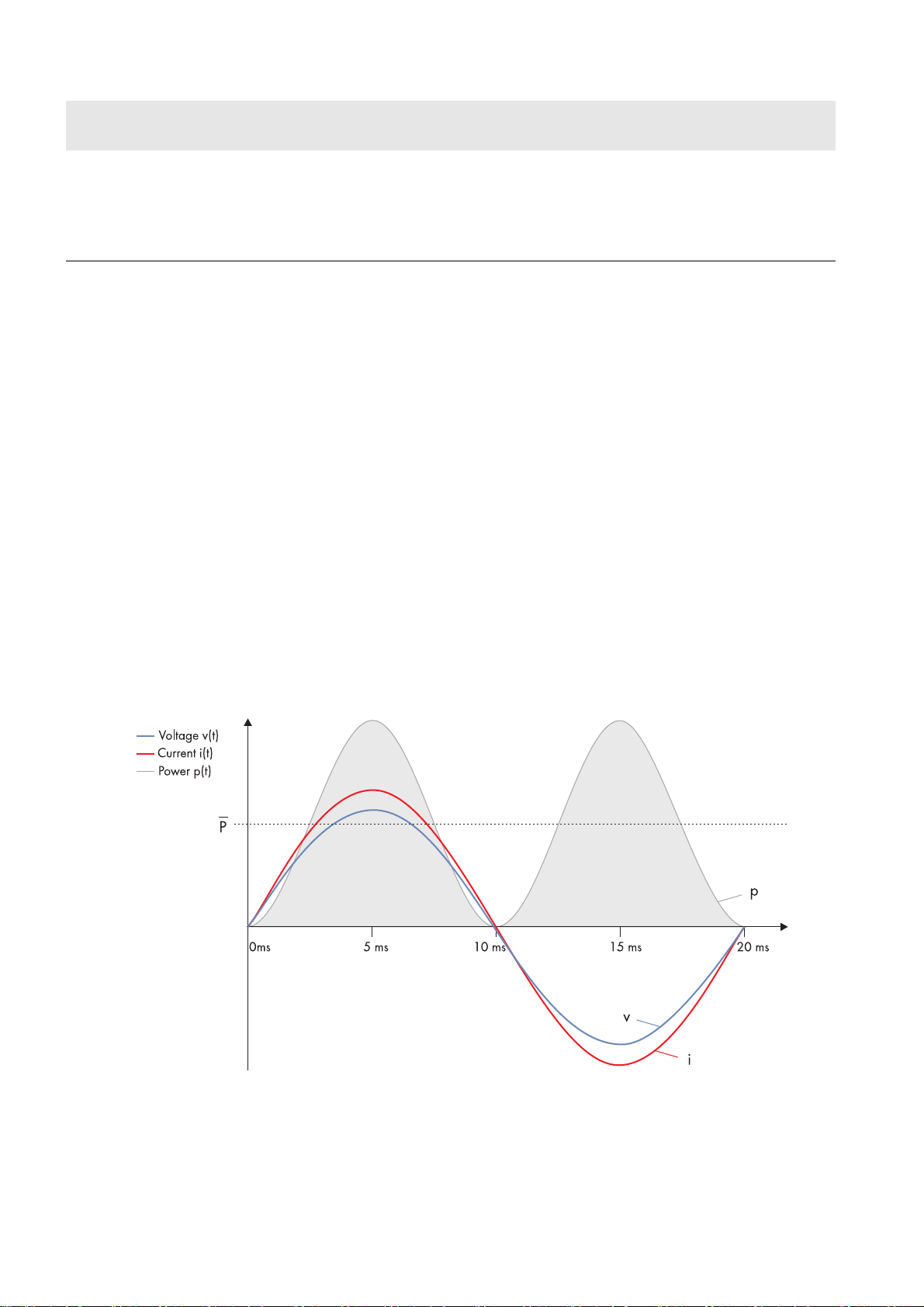
With no phase shift between progression of current i(t) and voltage v(t) over time, both always have the same sign and
simultaneously reach their maximum and minimum values. The power oscillates between zero and the positive maximum
value. Averaged over time, this results in a positive power value P (unit: W; Watt) and only active power is generated P.
This behavior occurs only when ohmic loads are the only loads in the electric circuit. In a real utility grid, however, cable
inductance and capacitance ensure that the active power is always accompanied by a small amount of reactive power.
Figure1: Pure active power: current and voltage are in phase
2 IPC_STP-TI-en-14 Technical Information
SMA Solar Technology AG 1 Definition of Active Power, Reactive Power and Apparent Power
1.2 Reactive Power Q
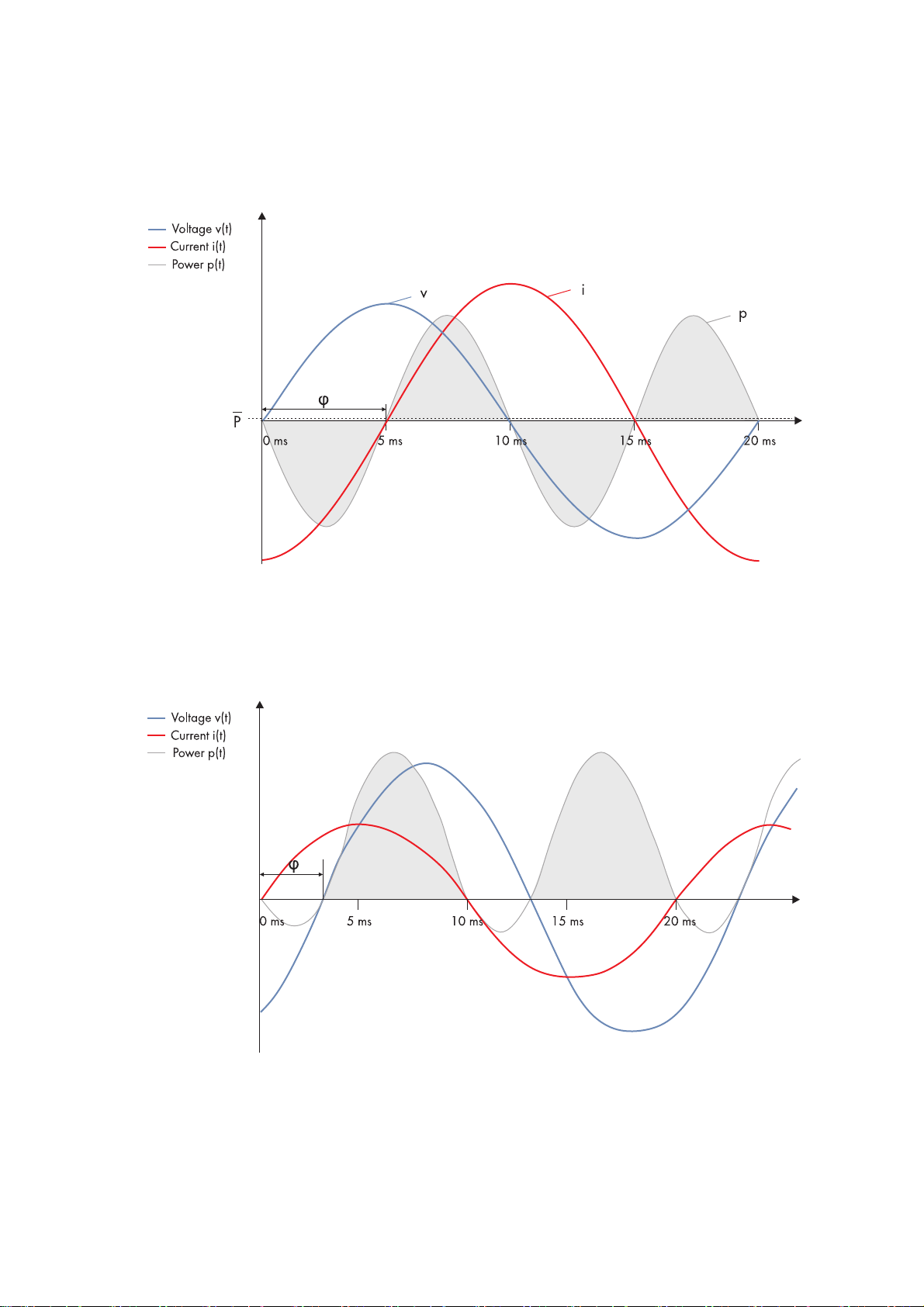
With a phase shift phi of 90°, the maximum current occurs precisely when the voltage crosses zero; then the power
oscillates between positive and negative values, which is why the average value over time is zero. This is known as pure
reactive power Q (unit: Var, from the French volt-ampère-réactif) which moves "back and forth" in the cables.
Figure2: Pure reactive power: current and voltage are phase-shifted by 90°
1.3 Apparent Power S
In real AC circuits, there is a mix of active power and reactive power. This behavior occurs when there are leading or
lagging loads in the utility grid. The shift between current and voltage is denoted by the displacement power factor cos φ.
Figure3: In real AC grids, current and voltage are slightly phase-shifted and reactive power occurs together with active power.
Technical Information IPC_STP-TI-en-14 3
1 Definition of Active Power, Reactive Power and Apparent Power SMA Solar Technology AG
Calculating Apparent Power
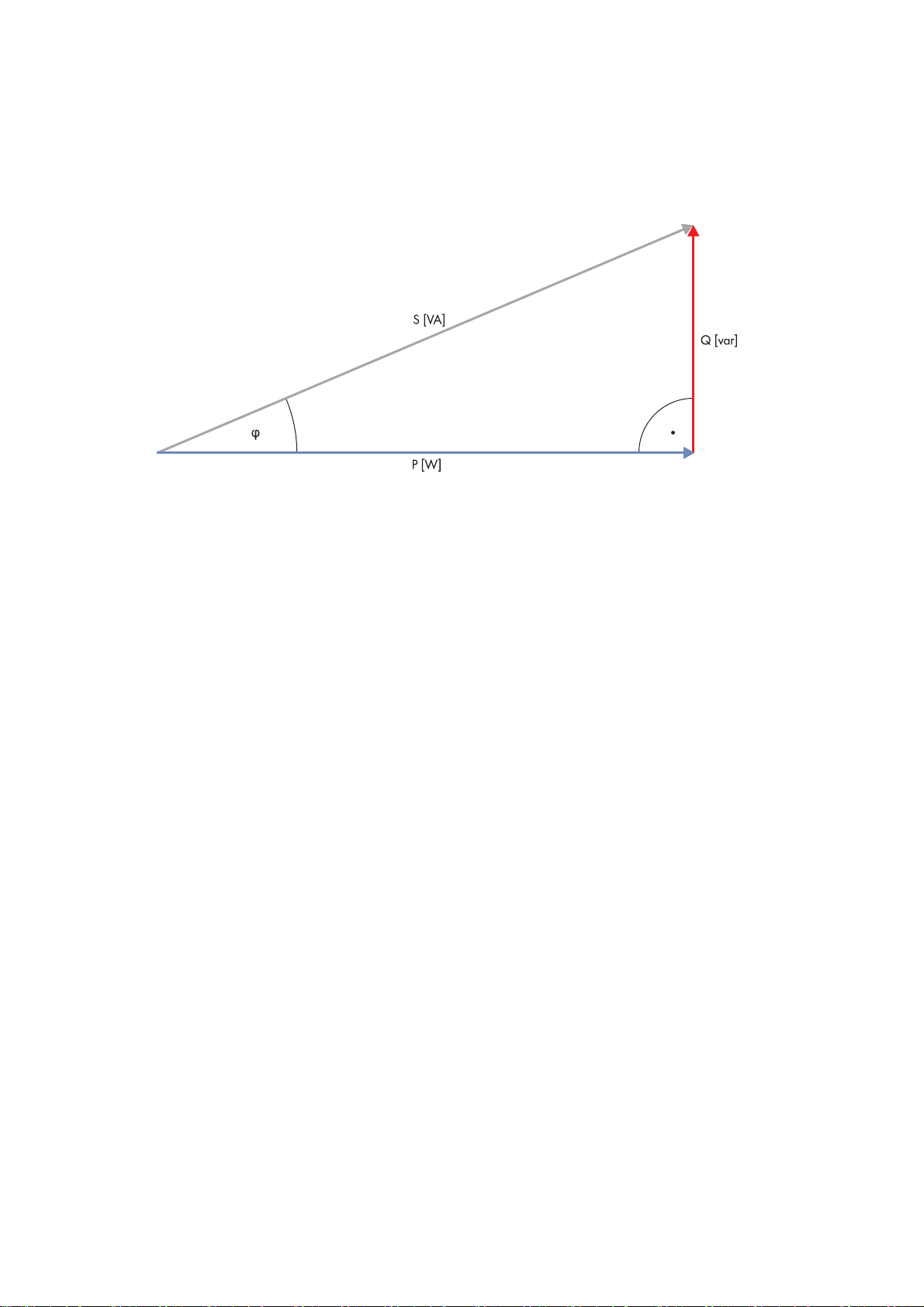
The sum of active power and reactive power is the so-called apparent power S (unit: VA; volt-ampère). It should be noted
that the units are not simply added arithmetically, but must be represented as vectors: active and reactive power form the
sides of a right triangle whose hypotenuse corresponds to the apparent power. The cosine of the angle between the
active power and the apparent power is the displacement power factor.
Figure4: Vector addition of active and reactive power
1.4 Compensating and Controlling Reactive Power with Sunny Tripower
Compensating Reactive Power Demand with Q on Demand 24/7
Leading or lagging loads (e.g. cables, transformers) require reactive power. Transporting reactive power from the power
plant to the load places a burden on the utility grid. It therefore makes sense to install a compensation system that provides
reactive power at sites with many leading or lagging loads. In order to ensure the stability of the utility grid, grid operators
require energy producers to take part in the compensation of reactive power. A PV system can complement or replace
such a compensation system.
Due to their design, large PV farms have a certain demand for reactive power which can be compensated with
Sunny Tripower inverters. At the same time, Sunny Tripower inverters can feed reactive power into the utility grid.
Compensation can take place both in feed-in and non-feed-in operation by using the Q on Demand 24/7 function.
Using this function, the Sunny Tripower inverter provides reactive power for the PV farm equipment without placing a
burden on the utility grid.
Controlling the Q(V) Characteristic Curve with Integrated Plant Control
The Sunny Tripower inverter can provide reactive power to the utility grid with the Integrated Plant Control function.
The grid operator specifies the preferred process by which the inverter should supply reactive power to the utility grid.
In many cases, the grid operator will require control in accordance with a Q(V) characteristic curve.
SMA inverters with Integrated Plant Control are capable of representing this Q(V) characteristic curve without performing
any measurement at the grid-connection point. The inverter can automatically compensate equipment installed between
the inverter and the grid-connection point.
The function "Integrated Plant Control" is not capable of compensating irregular or fluctuating reactive power demands
— e.g. from connected machinery — when the machinery is connected between the inverters and the grid-connection point.
If the machinery is connected directly at the grid-connection point, it is possible to dynamically determine the reactive
power demand of the machines using additional measurement equipment and then to provide this value as an offset to
the Q(V) control.
4 IPC_STP-TI-en-14 Technical Information
 Loading...