

SMA STP 15000TL-30, Sunny Tripower 15000TL, STP 20000TL-30, Sunny Tripower 25000TL, Sunny Tripower 20000TL Operating Manual
...
Operating Manual
SUNNY TRIPOWER 15000TL / 20000TL /
25000TL
STP15-25TL-30-BE-en-13 | Version 1.3ENGLISH

Legal Provisions
SMA Solar Technology AG
Legal Provisions
The information contained in these documents is property of SMA Solar Technology AG. Any
publication, whether in whole or in part, requires prior written approval by SMA Solar Technology
AG. Internal reproduction used solely for the purpose of product evaluation or other proper use is
allowed and does not require prior approval.
SMA Warranty
You can download the current warranty conditions from the Internet at www.SMA-Solar.com.
Trademarks
All trademarks are recognized, even if not explicitly identified as such. Missing designations do not
mean that a product or brand is not a registered trademark.
Modbus® is a registered trademark of SchneiderElectric and is licensed by the
ModbusOrganization,Inc.
QRCode is a registered trademark of DENSOWAVEINCORPORATED.
Phillips® and Pozidriv® are registered trademarks of PhillipsScrewCompany.
Torx® is a registered trademark of AcumentGlobalTechnologies,Inc.
SMA Solar Technology AG
Sonnenallee 1
34266 Niestetal
Germany
Tel. +49 561 9522-0
Fax +49 561 9522-100
www.SMA.de
Email: info@SMA.de
Copyright © 2016 SMA Solar Technology AG. All rights reserved.
Operating ManualSTP15-25TL-30-BE-en-132

SMA Solar Technology AG
Table of Contents
Table of Contents
1 Information on this Document................................................. 5
1.1 Validity ............................................................................................... 5
1.2 Target group ...................................................................................... 5
1.3 Additional Information....................................................................... 5
1.4 Symbols.............................................................................................. 6
1.5 Nomenclature.................................................................................... 7
2 Safety ........................................................................................ 8
2.1 Intended Use...................................................................................... 8
2.2 Safety Information ............................................................................. 8
3 Scope of Delivery ..................................................................... 10
4 Product Description .................................................................. 11
4.1 Sunny Tripower.................................................................................. 11
4.2 Interfaces and Functions.................................................................... 13
5 Mounting................................................................................... 16
5.1 Requirements for Mounting............................................................... 16
5.2 Mounting the Inverter........................................................................ 18
6 Electrical Connection ................................................................ 21
6.1 Safety during Electrical Connection ................................................. 21
6.2 Overview of the Connection Area.................................................... 22
6.2.1 View from Below............................................................................ 22
6.2.2 Interior View................................................................................... 23
6.3 AC Connection .................................................................................. 23
6.3.1 Requirements for the AC Connection........................................... 23
6.3.2 Connecting the Inverter to the Utility Grid ................................... 25
6.3.3 Connecting Additional Grounding............................................... 27
6.4 DC Connection .................................................................................. 28
6.4.1 Requirements for the DC Connection........................................... 28
6.4.2 Connecting the PV Array............................................................... 28
7 Commissioning ......................................................................... 31
7.1 Commissioning Procedure................................................................. 31
Operating Manual 3STP15-25TL-30-BE-en-13

Table of Contents
SMA Solar Technology AG
7.2 Configuring the Country Data Set.................................................... 31
7.3 Commissioning the Inverter............................................................... 32
8 Configuration............................................................................ 35
8.1 Configuration Procedure................................................................... 35
8.2 Integrating the Inverter into the Network ......................................... 35
8.3 Changing Operating Parameters ..................................................... 36
8.4 Setting the Active Power Limitation in case of PV System Control
Failure................................................................................................. 36
8.5 Configuring the Modbus Function.................................................... 37
8.6 Reducing the Attenuation of Ripple Control Signals ....................... 37
8.7 Setting SMA OptiTrac Global Peak................................................. 38
9 Operation ................................................................................. 39
9.1 LED Signals ........................................................................................ 39
9.2 Display Overview.............................................................................. 39
9.3 Activating and Operating the Display ............................................. 41
9.4 Calling Up Display Messages of the Start-Up Phase...................... 42
10 Disconnecting the Inverter from Voltage Sources ................. 43
11 Technical Data .......................................................................... 46
12 Accessories ............................................................................... 51
13 Contact ...................................................................................... 52
14 EU Declaration of Conformity ................................................. 54
Operating ManualSTP15-25TL-30-BE-en-134

SMA Solar Technology AG
1 Information on this Document
1 Information on this Document
1.1 Validity
This document is valid for the following device types:
• STP 15000TL-30 (Sunny Tripower 15000TL)
• STP 20000TL-30 (Sunny Tripower 20000TL)
• STP 25000TL-30 (Sunny Tripower 25000TL)
1.2 Target group
This document is intended for qualified persons and end users. Only qualified persons are allowed
to perform the activities marked in this document with a warning symbol and the caption
"Qualifiedperson". Tasks that do not require any particular qualification are not marked and can
also be performed by end users. Qualified persons must have the following skills:
• Knowledge of how an inverter works and is operated
• Training in how to deal with the dangers and risks associated with installing and using
electrical devices and installations
• Training in the installation and commissioning of electrical devices and installations
• Knowledge of the applicable standards and directives
• Knowledge of and compliance with this document and all safety information
1.3 Additional Information
Links to additional information can be found at www.SMA-Solar.com:
Document title and content Document type
Troubleshooting, cleaning, replacement of surge arresters
typeII and decommissioning
"Application for SMAGridGuard Code" Form
"SMASpeedwire/Webconnect Data Module"
Connection to the Speedwire/Webconnect data module
"Webconnect Systems in SunnyPortal"
Registration in SunnyPortal and setting or changing operating
parameters of the inverter
"Overview of the Rotary Switch Settings"
Overview of the rotary switch settings for configuring the coun-
try data set and display language
"Efficiency and Derating"
Efficiency and Derating Behavior of the SunnyBoy,
SunnyTripower and SunnyMiniCentral Inverters
Service Manual
Installation Manual
User Manual
Technical Information
Technical Information
Operating Manual 5STP15-25TL-30-BE-en-13
1 Information on this Document
Document title and content Document type
"Criteria for Selecting a Residual-Current Device" Technical Information
"Circuit Breaker"
Dimensioning and Selection of a Suitable AC Circuit Breaker
for Inverters under PV-Specific Influences
"Insulation Resistance (Riso) of Non-Galvanically Isolated PV
Systems"
Calculating the insulation resistance for troubleshooting
"IntegratedPlantControl and QonDemand24/7"
Detailed explanation of functions and description for setting the
functions
"Shade Management"
Efficient operation of partly shaded PV systems with Opti-
TracGlobalPeak
"Leading Leakage Currents"
Information on the Design of Transformerless Inverters
"Firmware Update with SD Card" Technical Description
"Parameter list"
Overview of All Inverter Operating Parameters and Their Configuration Options
"SMAModbus® Interface"
Information on the commissioning and configuration of the
SMA Modbus interface
"SMA Modbus® Interface"
List with the product specific SMA Modbus registers
"SunSpec® Modbus® Interface"
Information on the commissioning and configuration of the SunSpec Modbus interface
"SunSpec® Modbus® Interface"
List with the product specific SunSpec Modbus registers
SMA Solar Technology AG
Technical Information
Technical Information
Technical Information
Technical Information
Technical Information
Technical Information
Technical Information
Technical Information
Technical Information
Technical Information
1.4 Symbols
Symbol Explanation
Indicates a hazardous situation which, if not
avoided, will result in death or serious injury
Indicates a hazardous situation which, if not
avoided, can result in death or serious injury
Operating ManualSTP15-25TL-30-BE-en-136
SMA Solar Technology AG
Symbol Explanation
Indicates a hazardous situation which, if not
avoided, can result in minor or moderate injury
Indicates a situation which, if not avoided, can result in property damage
Sections describing activities to be performed by
qualified persons only
Information that is important for a specific topic or
goal, but is not safety-relevant
Indicates a requirement for meeting a specific goal
Desired result
A problem that might occur
1 Information on this Document
1.5 Nomenclature
Complete designation Designation in this document
SunnyTripower Inverter, product
Operating Manual 7STP15-25TL-30-BE-en-13

2 Safety
SMA Solar Technology AG
2 Safety
2.1 Intended Use
The SunnyTripower is a transformerless PV inverter with two MPP trackers which converts the direct
current of the PV array to grid-compliant three-phase current and feeds it into the utility grid.
The product is suitable for indoor and outdoor use.
The product must only be operated with PV arrays of protection class II in accordance with
IEC61730, application class A. The PV modules must be compatible with this product.
PV modules with a high capacity to ground must only be used if their coupling capacity does not
exceed 3.5 μF (for information on how to calculate the coupling capacity, see the Technical
Information "Leading Leakage Currents" at www.SMA-Solar.com).
All components must remain within their permitted operating ranges at all times.
The product must only be used in countries for which it is approved or released by SMA Solar
Technology AG and the grid operator.
The product is also approved for the Australian market and may be used in Australia. If DRM
support is specified, the inverter may only be used in conjunction with a Demand Response
Enabling Device (DRED). This ensures that the inverter implements the commands from the grid
operator for active power limitation at all times. The inverter and the Demand Response Enabling
Device (DRED) must be connected in the same network and the inverter Modbus interface must be
activated and the TCP server set.
Use this product only in accordance with the information provided in the enclosed documentation
and with the locally applicable standards and directives. Any other application may cause
personal injury or property damage.
Alterations to the product, e.g. changes or modifications, are only permitted with the express written
permission of SMA Solar Technology AG. Unauthorized alterations will void guarantee and
warranty claims and in most cases terminate the operating license. SMA Solar Technology AG
shall not be held liable for any damage caused by such changes.
Any use of the product other than that described in the Intended Use section does not qualify as
appropriate.
The enclosed documentation is an integral part of this product. Keep the documentation in a
convenient place for future reference and observe all instructions contained therein.
The type label must remain permanently attached to the product.
2.2 Safety Information
This section contains safety information that must be observed at all times when working on or with
the product.
To prevent personal injury and property damage and to ensure long-term operation of the product,
read this section carefully and observe all safety information at all times.
Operating ManualSTP15-25TL-30-BE-en-138
SMA Solar Technology AG
2 Safety
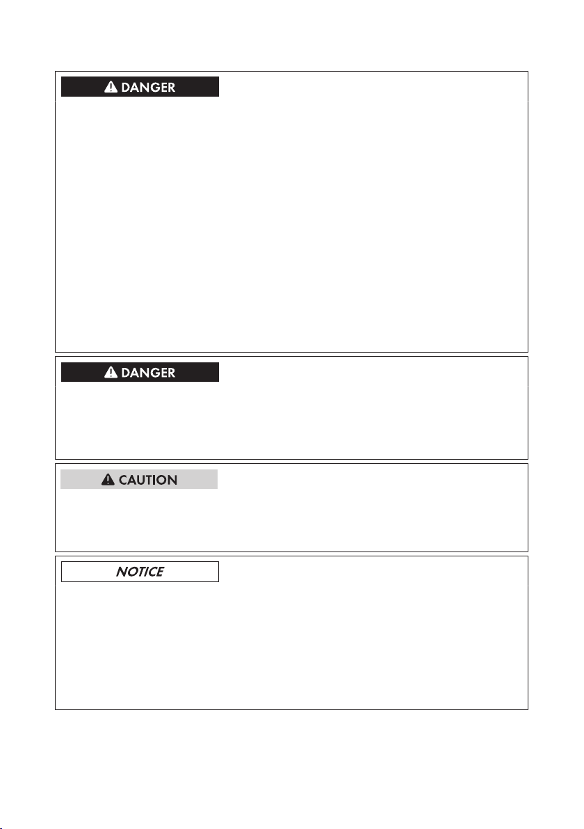
Danger to life due to high voltages of the PV array
When exposed to sunlight, the PV array generates dangerous DC voltage which is present in the
DC conductors and the live components of the inverter. Touching the DC conductors or the live
components can lead to lethal electric shocks. If you disconnect the DC connectors from the
inverter under load, an electric arc may occur leading to electric shock and burns.
• Do not touch non-insulated cable ends.
• Do not touch the DC conductors.
• Do not touch any live components of the inverter.
• Have the inverter mounted, installed and commissioned only by qualified persons with the
appropriate skills.
• If an error occurs, have it rectified by qualified persons only.
• Prior to performing any work on the inverter, disconnect it from all voltage sources as
described in this document (see Section10 "Disconnecting the Inverter from Voltage
Sources", page43).
Danger to life due to electric shock
Touching an ungrounded PV module or array frame can cause a lethal electric shock.
• Connect and ground the PV modules, array frame and electrically conductive surfaces so
that there is continuous conduction. Observe the applicable local regulations.
Risk of burns due to hot enclosure parts
Some parts of the enclosure can get hot during operation.
• Do not touch any parts other than the lower enclosure lid of the inverter during operation.
Damage to seals on the enclosure lids in subfreezing conditions
If you open the upper and lower enclosure lids when temperatures are below freezing, the
enclosure seals can be damaged. This can lead to moisture entering the inverter.
• Do not open the inverter at ambient temperatures lower than -5°C.
• If a layer of ice has formed on the seal of the lid when temperatures are below freezing,
remove it prior to opening the enclosure lids of the inverter (e.g. by melting the ice with
warm air). Observe the applicable safety regulations.
Operating Manual 9STP15-25TL-30-BE-en-13
ABCD
(N
am
e des G
erätes):
Bitte füllen Sie die folgenden Felder aus:
:
Typ:
Seriennummer:
Datum der Inbetriebnahme:
Anschrift:
Installationsbetrieb
Typ:
Seriennummer:
Datum der Inbetriebnahme:
Anschrift:
Installationsbetrieb
G
ew
ährleistungs- und Garantiebedingungen
FGE
_
+
HIK
N
OP Q
L
M
3 Scope of Delivery
SMA Solar Technology AG
3 Scope of Delivery
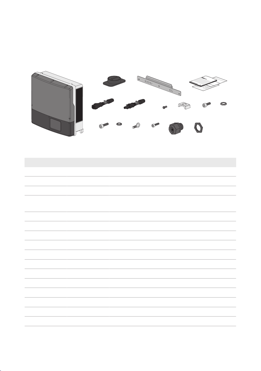
Check the scope of delivery for completeness and any externally visible damage. Contact your
distributor if the scope of delivery is incomplete or damaged.
The delivery may contain parts that are not required for the installation of this inverter.
Figure 1: Components included in the scope of delivery
Position Quantity Designation
A 1 Inverter
B 1 DC load-break switch
C 1 Wall mounting bracket
D 1 Quick installation guide, supplementary sheet with default
settings, installation manual of the DC connectors
E 6 Negative DC connector
F 6 Positive DC connector
G 12 Sealing plug
H 1 Clamping bracket
I 1 Cylindrical screw M6x16
K 1 Conical spring washer M6
L 2 Cylindrical screw M5x20*
M 2 Conical spring washer M5*
N 1 Eye bolt M8
O 2 Cylindrical screw M5x10
P 1 AC cable gland
Q 1 Counter nut
* Spare part for the enclosure lid
Operating ManualSTP15-25TL-30-BE-en-1310
B
E
G
H
C
A
D
A
F
I
SMA Solar Technology AG
4 Product Description
4 Product Description
4.1 SunnyTripower
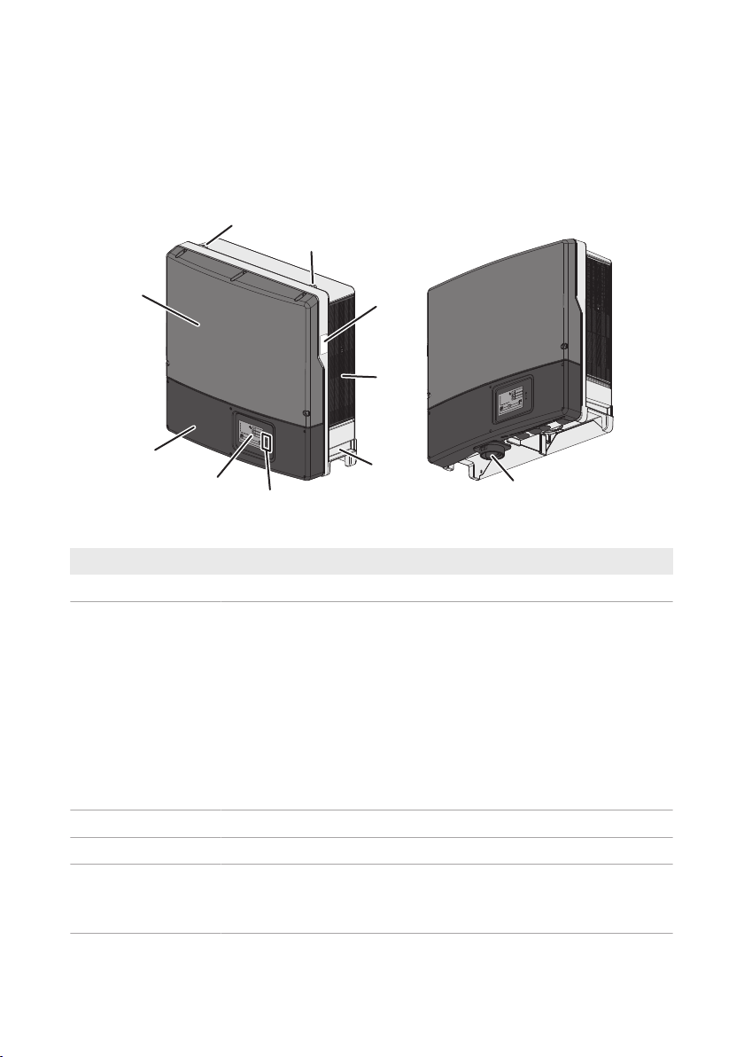
The SunnyTripower is a transformerless PV inverter with two MPP trackers which converts the direct
current of the PV array to grid-compliant three-phase current and feeds it into the utility grid.
Figure 2: Design of the SunnyTripower
Position Designation
A Thread for screwing in two eye bolts for transport
B Type label
The type label uniquely identifies the inverter. You will require the information on the type label to use the product safely and when seeking customer support from the SMAServiceLine. You will find the following information on the type label:
• Device type (Model)
• Serial number (SerialNo.)
C Ventilation grid
D Recessed grip
E LEDs
• Date of manufacture
• Device-specific characteristics
The LEDs indicate the operating state of the inverter (see Section9.1 "LED
Signals", page39).
Operating Manual 11STP15-25TL-30-BE-en-13
4 Product Description
Position Designation
F Display (optional)
The display shows the current operating data and events or errors (see
service manual at www.SMA-Solar.com).
G Lower enclosure lid
H Upper enclosure lid
I DC load-break switch
The inverter is equipped with a DC load-break switch. If the DC load-
break switch is set to the position I, it establishes a conductive connection
between the PV array and the inverter. Setting the DC load-break switch
to the O position interrupts the DC electric circuit and completely discon-
nects the PV array from the inverter. Disconnection takes place at all
poles.
Symbols on the Inverter and on the Type Label
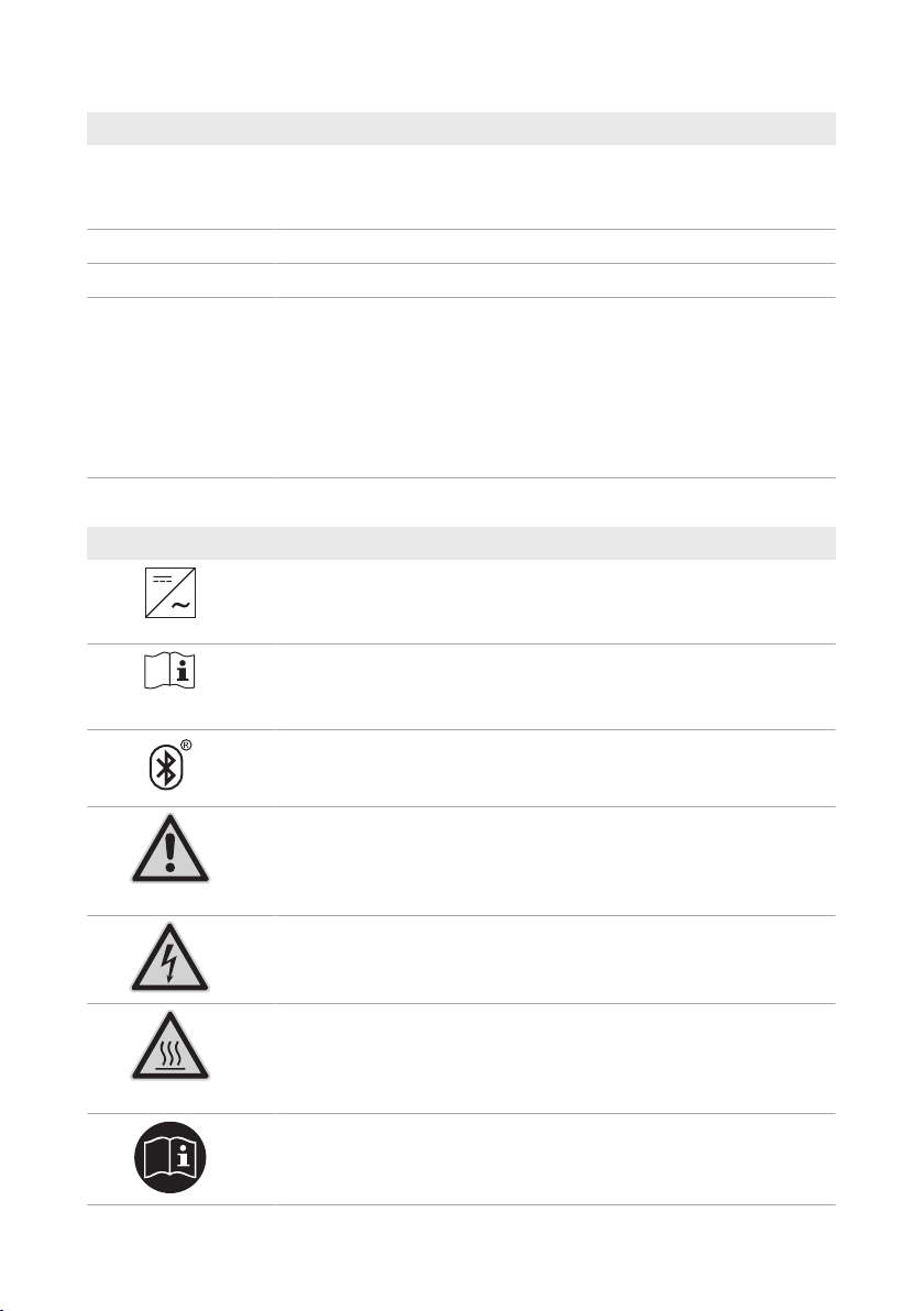
Symbol Explanation
Inverter
Together with the green LED, this symbol indicates the operating state of
the inverter.
Observe the documentation
Together with the red LED, this symbol indicates an error (for trou-
bleshooting, see the service manual at www.SMA-Solar.com).
BLUETOOTH
No function. The inverter is equipped with Speedwire/Webconnect.
SMA Solar Technology AG
Danger
This symbol indicates that the inverter must be additionally grounded if a
second grounding conductor or equipotential bonding is required locally
(see Section6.3.3 "Connecting Additional Grounding", page27).
Danger to life due to electric shock
The product operates at high voltages. All work on the product must be
carried out by qualified persons only.
Risk of burns due to hot surfaces
The product can get hot during operation. Avoid contact during opera-
tion. Allow the product to cool down sufficiently before carrying out any
work.
Observe the documentation
Observe all documentation supplied with the product.
Operating ManualSTP15-25TL-30-BE-en-1312

SMA Solar Technology AG
Symbol Explanation
Direct current
The product does not have a transformer.
Three-phase alternating current with neutral conductor
WEEE designation
Do not dispose of the product together with the household waste but in
accordance with the locally applicable disposal regulations for electronic
waste.
CE marking
The product complies with the requirements of the applicable EU direc-
tives.
Degree of protectionIP65
The product is protected against dust intrusion and water jets from any
angle.
The product is suitable for outdoor installation.
4 Product Description
RCM (Regulatory Compliance Mark)
The product complies with the requirements of the applicable Australian
standards.
4.2 Interfaces and Functions
The inverter can be equipped or retrofitted with the following interfaces and functions:
SMASpeedwire/Webconnect
The inverter is equipped with SMA Speedwire/Webconnect as standard. SMA Speedwire/
Webconnect is a type of communication based on the Ethernet standard. This enables inverteroptimized 10/100Mbit data transmission between Speedwire devices in PV systems and the
software Sunny Explorer. The Webconnect function enables direct data transmission between the
inverters of a small-scale system and the Internet portal SunnyPortal without any additional
Operating Manual 13STP15-25TL-30-BE-en-13

4 Product Description
communication device and for a maximum of 4 inverters per SunnyPortal system. In large-scale PV
power plants, data transmission to the Internet portal SunnyPortal is carried out via the
SMAClusterController. You can access your SunnyPortal system from any computer with an
Internet connection.
Webconnect enables - for PV systems operated in Italy - the connection or disconnection of the
inverter to or from the utility grid and the specifying of the frequency limits to be used via
IEC61850-GOOSE messages.
SMA Solar Technology AG
RS485 Interface
The inverter can communicate via cables with special SMA communication products via the RS485
interface (information on supported SMAproducts at www.SMA-Solar.com). The RS485 interface
can be retrofitted and can be used in place of the SMASpeedwire/Webconnect interface in the
inverter.
Modbus
The inverter is equipped with a Modbus interface. The Modbus interface is deactivated by default
and must be configured as needed.
The Modbus interface of the supported SMA devices is designed for industrial use and has the
following tasks:
• Remote query of measured values
• Remote setting of operating parameters
• Setpoint specifications for system control
Grid Management Services
The inverter is equipped with service functions for grid management.
Depending on the requirements of the grid operator, you can activate and configure the functions
(e.g. active power limitation) via operating parameters.
SMA Power Control Module
The SMAPowerControlModule enables the inverter to implement grid management services and
is equipped with an additional multifunction relay (for information on installation and configuration,
see the installation manual of the SMAPowerControlModule). The SMAPowerControlModule
can be retrofitted.
Multifunction Relay
You can configure the multifunction relay for various operating modes. The multifunction relay is
used, for example, to switch fault indicators on or off (for information on installation and
configuration, see the installation manual of the multifunction relay). The multifunction relay can be
retrofitted.
Operating ManualSTP15-25TL-30-BE-en-1314

SMA Solar Technology AG
4 Product Description
SMAOptiTracGlobalPeak
SMAOptiTracGlobalPeak is an advancement of SMAOptiTrac and allows the operating point of
the inverter to follow the optimal operating point of the PV array (MPP) precisely at all times. In
addition, with the aid of SMAOptiTracGlobalPeak, the inverter detects several maximum power
points in the available operating range, such as may occur particularly with partially shaded
strings. SMA OptiTrac Global Peak is enabled by default.
Surge arrester type II
Surge arresters limit dangerous overvoltages. Surge arresters of typeII can be retrofitted (for details
on the installation refer to the service manual of the inverter at www.SMA-Solar.com).
QonDemand 24/7
The inverter can supply reactive power by means of QonDemand24/7 covering the entire unit
circle around the clock (for details on the configuration refer to the Technical Information
"IntegratedPlantControl and QonDemand24/7" at www.SMA-Solar.com).
IntegratedPlantControl
The inverter can display the Q(V) characteristic curve specified by the grid operator by means of
IntegratedPlantControl without measuring on the grid-connection point. The inverter can
automatically compensate equipment installed between the inverter and the grid-connection point
after having activated the function (for information on the system configuration refer to the Technical
Information "IntegratedPlantControl and QonDemand24/7" at www.SMA-Solar.com).
Operating Manual 15STP15-25TL-30-BE-en-13
5 Mounting
SMA Solar Technology AG
5 Mounting
5.1 Requirements for Mounting
Requirements for the mounting location:
Danger to life due to fire or explosion
Despite careful construction, electrical devices can cause fires.
• Do not mount the inverter in areas containing highly flammable materials or gases.
• Do not mount the inverter in a potentially explosive atmosphere.
☐ Do not mount the inverter on a pillar.
☐ The mounting location must be inaccessible to children.
☐ A solid support surface must be available for mounting, e.g. concrete or masonry. When
mounted on drywall or similar materials, the inverter emits audible vibrations during operation
which could be perceived as annoying.
☐ The mounting location must be suitable for the weight and dimensions of the inverter (see
Section11 "Technical Data", page46).
☐ The mounting location must not be exposed to direct solar irradiation. Direct solar irradiation
can result in the premature aging of the exterior plastic parts of the inverter and direct solar
irradiation can cause the inverter to overheat. When becoming too hot, the inverter reduces
its power output to avoid overheating.
☐ The mounting location should be freely and safely accessible at all times without the need for
any auxiliary equipment (such as scaffolding or lifting platforms). Non-fulfillment of these
criteria may restrict servicing.
☐ To ensure optimum operation, the ambient temperature should be between -25°C and 40°C.
☐ Climatic conditions must be met (see Section11 "Technical Data", page46).
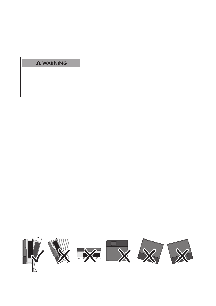
Permitted and prohibited mounting positions:
☐ The inverter must only be mounted in one of the permitted positions. This will ensure that no
moisture can penetrate the inverter.
☐ The inverter should be mounted in such a way that LED signals can be read without difficulty.
Figure 3: Permitted and prohibited mounting positions:
Operating ManualSTP15-25TL-30-BE-en-1316
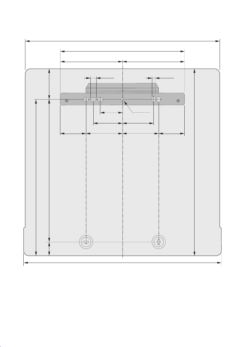
638 mm
432 mm
216 mm 216 mm
20 mm 11 mm
79 mm Ø 11 mm
112 mm
105 mm
110 mm
86 mm
130 mm 86 mm
467 mm
619 mm
40 mm
130 mm
648 mm
507 mm
SMA Solar Technology AG
Dimensions for mounting:
5 Mounting
Figure 4: Position of the anchoring points
Recommended clearances:
If you maintain the recommended clearances, adequate heat dissipation will be ensured. Thus, you
will prevent power reduction due to excessive temperature.
☐ Maintain the recommended clearances to walls as well as to other inverters or objects.
☐ If multiple inverters are mounted in areas with high ambient temperatures, increase the
clearances between the inverters and ensure sufficient fresh-air supply.
Operating Manual 17STP15-25TL-30-BE-en-13
 Loading...