

Page 1

US
Mounting Rack
SUNNY TOWER-US ST6US/ST36/ST42/ST48
Installation Guide
ST36-48US-IA-IUS112321 | IMUS-ST36-48 | Version 2.1
Page 2

Page 3

SMA America, LLC Legal Restrictions
Copyright © 2011 SMA America,LLC. All rights reserved.
No part of this document may be reproduced, stored in a retrieval system, or transmitted, in any form
or by any means, electronic, mechanical, photographic, magnetic or otherwise, without the prior
written permission of SMA America,LLC.
Neither SMA America,LLC nor SMA Solar Technology Canada Inc. makes representations, express
or implied, with respect to this documentation or any of the equipment and/or software it may
describe, including (with no limitation) any implied warranties of utility, merchantability, or fitness for
any particular purpose. All such warranties are expressly disclaimed. Neither SMA America,LLC nor
its distributors or dealers nor SMA Solar Technology Canada Inc. nor its distributors or dealers shall
be liable for any indirect, incidental, or consequential damages under any circumstances.
(The exclusion of implied warranties may not apply in all cases under some statutes, and thus the
above exclusion may not apply.)
Specifications are subject to change without notice. Every attempt has been made to make this
document complete, accurate and up-to-date. Readers are cautioned, however, that
SMAAmerica,LLC and SMA Solar Technology Canada Inc. reserve the right to make changes
without notice and shall not be responsible for any damages, including indirect, incidental or
consequential damages, caused by reliance on the material presented, including, but not limited to,
omissions, typographical errors, arithmetical errors or listing errors in the content material.
All trademarks are recognized even if these are not marked separately. Missing designations do not
mean that a product or brand is not a registered trademark.
The Bluetooth
®
word mark and logos are registered trademarks owned by Bluetooth SIG, Inc. and
any use of such marks by SMA America,LLC and SMA Solar Technology Canada Inc. is under
license.
SMA America, LLC
3801 N. Havana Street
Denver, CO 80239 U.S.A.
SMA Solar Technology Canada Inc.
2425 Matheson Blvd. E, 8th Floor
Mississauga, ON L4W 5K5, Canada
Installation Guide ST36-48US-IA-IUS112321 3
Page 4
Important Safety Instructions SMA America, LLC
IMPORTANT SAFETY INSTRUCTIONS
SAVE THESE INSTRUCTIONS
This manual contains important instructions for the following products:
•Sunny Tower-US
This manual must be followed during installation and maintenance.
The product is designed and tested according to international safety requirements, but as with all
electrical and electronic equipment, certain precautions must be observed when installing and/or
operating the product. To reduce the risk of personal injury and to ensure the safe installation and
operation of the product, you must carefully read and follow all instructions, cautions and warnings
in this manual.
Warnings in this document
A warning describes a hazard to equipment or personnel. It calls attention to a procedure or practice,
which, if not correctly performed or adhered to, could result in damage to or destruction of part or all
of the SMA equipment and/or other equipment connected to the SMA equipment or personal injury.
DANGER
DANGER indicates a hazardous situation which, if not avoided, will result in death or
serious injury.
WARNING
WARNING indicates a hazardous situation which, if not avoided, could result in death or
serious injury.
CAUTION
CAUTION indicates a hazardous situation which, if not avoided, could result in minor or
moderate injury.
NOTICE
NOTICE is used to address practices not related to personal injury.
4 ST36-48US-IA-IUS112321 Installation Guide
Page 5

SMA America, LLC Important Safety Instructions
Other symbols in this document
In addition to the safety and hazard symbols described on the previous pages, the following symbol
is also used in this manual:
Information
This symbol accompanies notes that call attention to supplementary information that you
must know and use to ensure optimal operation of the system.
Markings on this product
The following symbols are used as product markings with the following meanings.
Warning regarding dangerous voltage
The product works with high voltages. All work on the product must only be performed
as described in the documentation of the product.
Electric arc hazards
The product has large electrical potential differences between its conductors. Arc flashes
can occur through air when high-voltage current flows. Do not work on the product
during operation.
Beware of hot surface
The product can become hot during operation. Do not touch the product during
operation.
Observe the operating instructions
Read the documentation of the product before working on it. Follow all safety
precautions and instructions as described in the documentation.
AC current
DC current
Earth Ground
UL1741 is the standard applied by Underwriters Laboratories to the product to certify
that it meets the requirements of the NationalElectricalCode
®
, the Canadian Electrical
Code® CSA C22.1 and IEEE‑929‑2000. IEEE 929-2000 provides recommendations
regarding the proper equipment and functionality necessary to ensure compatible
operation when power generation is connected to the utility grid.
Installation Guide ST36-48US-IA-IUS112321 5
Page 6

General Warnings SMA America, LLC
General warnings
General warnings
All electrical installations must be done in accordance with the local and
NationalElectrical Code
®
ANSI/NFPA 70 or the Canadian Electrical Code®
CSAC22.1. This document does not and is not intended to replace any local, state,
provincial, federal or national laws, regulation or codes applicable to the installation and
use of the product, including without limitation applicable electrical safety codes. All
installations must conform with the laws, regulations, codes and standards applicable in
the jurisdiction of installation. SMA assumes no responsibility for the compliance or
noncompliance with such laws or codes in connection with the installation of the product.
The product contains no user-serviceable parts except for the fans on the bottom of the
enclosure and the filters behind the fans as well as the handle covers on the sides of the
unit. For all repair and maintenance, always return the unit to an authorized SMA Service
Center.
Before installing or using the product, read all of the instructions, cautions, and warnings in
this manual.
Before connecting the product to the electrical utility grid, contact the local utility company.
This connection must be made only by qualified personnel.
Wiring of the product must be made by qualified personnel only.
6 ST36-48US-IA-IUS112321 Installation Guide
Page 7

SMA America, LLC Table of Contents
Table of Contents
1 Notes on this manual. . . . . . . . . . . . . . . . . . . . . . . . . . . . . . 9
1.1 Validity . . . . . . . . . . . . . . . . . . . . . . . . . . . . . . . . . . . . . . . . . . . . 9
1.2 Target group . . . . . . . . . . . . . . . . . . . . . . . . . . . . . . . . . . . . . . . . 9
1.3 Nomenclature. . . . . . . . . . . . . . . . . . . . . . . . . . . . . . . . . . . . . . . 9
2 The Sunny Tower . . . . . . . . . . . . . . . . . . . . . . . . . . . . . . . . 10
2.1 Appropriate usage . . . . . . . . . . . . . . . . . . . . . . . . . . . . . . . . . . 10
2.2 Device overview . . . . . . . . . . . . . . . . . . . . . . . . . . . . . . . . . . . . 10
2.3 Dimensions . . . . . . . . . . . . . . . . . . . . . . . . . . . . . . . . . . . . . . . . 12
2.4 Type plate. . . . . . . . . . . . . . . . . . . . . . . . . . . . . . . . . . . . . . . . . 13
2.5 Sunny WebBox. . . . . . . . . . . . . . . . . . . . . . . . . . . . . . . . . . . . . 13
3 Safety . . . . . . . . . . . . . . . . . . . . . . . . . . . . . . . . . . . . . . . . . 14
4 Installation . . . . . . . . . . . . . . . . . . . . . . . . . . . . . . . . . . . . . 15
4.1 Required tools and materials . . . . . . . . . . . . . . . . . . . . . . . . . . 15
4.2 Installing the Sunny Tower . . . . . . . . . . . . . . . . . . . . . . . . . . . . 15
4.2.1 Foundation . . . . . . . . . . . . . . . . . . . . . . . . . . . . . . . . . . . . . . . . . . . . . . . . . . 15
4.2.2 Minimum workspace/ventilation requirements . . . . . . . . . . . . . . . . . . . . . . . 16
4.3 Installing at the site . . . . . . . . . . . . . . . . . . . . . . . . . . . . . . . . . . 16
5 Attaching the conduits . . . . . . . . . . . . . . . . . . . . . . . . . . . . 18
5.1 Insert cables from the rear into the Sunny Tower . . . . . . . . . . . 18
5.2 Insert cables from below into the Sunny Tower . . . . . . . . . . . . 19
6 Opening and closing the Sunny Tower . . . . . . . . . . . . . . 21
6.1 Opening the Sunny Tower . . . . . . . . . . . . . . . . . . . . . . . . . . . . 21
6.2 Closing the Sunny Tower . . . . . . . . . . . . . . . . . . . . . . . . . . . . . 23
6.3 Opening and closing the Sunny Boy . . . . . . . . . . . . . . . . . . . . 23
7 Electrical connection. . . . . . . . . . . . . . . . . . . . . . . . . . . . . . 24
Installation Guide ST36-48US-IA-IUS112321 7
Page 8

Table of Contents SMA America, LLC
7.1 Connecting ground. . . . . . . . . . . . . . . . . . . . . . . . . . . . . . . . . . 25
7.2 Grid configuration. . . . . . . . . . . . . . . . . . . . . . . . . . . . . . . . . . . 26
7.3 Connecting the AC output . . . . . . . . . . . . . . . . . . . . . . . . . . . . 28
7.4 Connecting the DC Input . . . . . . . . . . . . . . . . . . . . . . . . . . . . . 30
7.5 Installing the inverters on the Sunny Tower . . . . . . . . . . . . . . . . 32
7.6 Wiring Connections to the Sunny Boy . . . . . . . . . . . . . . . . . . . 33
7.6.1 AC Wiring of the SB 6000US/SB 7000US/SB 8000US . . . . . . . . . . . . . . 34
7.6.2 DC wiring of the SB 6000US/SB 7000US/SB 8000US. . . . . . . . . . . . . . . 37
8 Communication. . . . . . . . . . . . . . . . . . . . . . . . . . . . . . . . . . 41
8.1 External communication device . . . . . . . . . . . . . . . . . . . . . . . . 41
8.2 Communication interface 485USPB-NR or 485USPB-SMC-NR 42
8.3 External communication device . . . . . . . . . . . . . . . . . . . . . . . . 43
8.4 Connecting another Sunny Tower. . . . . . . . . . . . . . . . . . . . . . . 44
8.5 Installing the Sunny WebBox . . . . . . . . . . . . . . . . . . . . . . . . . . 46
9 Commissioning the Sunny Tower . . . . . . . . . . . . . . . . . . . 49
10 Cleaning and maintenance . . . . . . . . . . . . . . . . . . . . . . . . 52
11 Technical data. . . . . . . . . . . . . . . . . . . . . . . . . . . . . . . . . . . 53
11.1 Sunny Tower ST36 equipped with Sunny Boy SB 6000US . . . 53
11.2 Sunny Tower ST42 equipped with Sunny Boy SB 7000US . . . 55
11.3 Sunny Tower ST48 equipped with Sunny Boy SB 8000US . . . 57
12 Contact . . . . . . . . . . . . . . . . . . . . . . . . . . . . . . . . . . . . . . . . 59
8 ST36-48US-IA-IUS112321 Installation Guide
Page 9

SMA America, LLC Notes on this manual
1 Notes on this manual
This manual describes the mounting, installation and commissionig of the Sunny Tower-US ST6US,
ST36, ST42 and ST48. This manual does not cover any details concerning equipment connected to
th e Su nny Tow er. In for mat ion con cer ning t he c onn ect ed e qui pme nt i s av ailab le f rom the manuf act ure r
of the equipment.
1.1 Validity
This manual is valid for the Sunny Tower types listed below:
ST6US
ST36
ST42
ST48
In this manual the listed types above are referred to as Sunny Tower.
1.2 Target group
This manual is for qualified personnel. Qualified personnel have received training and have
demonstrated skills and knowledge in the construction and operation of the device. Qualified
personnel is trained to deal with the dangers and hazards involved in installing electric devices.
1.3 Nomenclature
In this document SMA America Production, LLC is referred to in the following as SMA.
Installation Guide ST36-48US-IA-IUS112321 9
Page 10

The Sunny Tower SMA America, LLC
2 The Sunny Tower
2.1 Appropriate usage
The Sunny Tower is a mounting frame which enables you to easily install six inverters of type
SB6000US, SB 7000US or SB 8000US. The AC and DC cabling is pre-wired, as is the
communication via RS485, and the AC/DC Disconnect.
An optional Sunny WebBox allows remote monitoring of the PV plant via an internet connection.
The Sunny Tower is delivered with a base plate for easy installation.
It is prohibited:
• to use the Sunny Tower for purposes other than those described here.
• to connect voltage sources to the inverter other than those consisting of PV-modules.
• to modify the Sunny Tower or to install components that are not explicitly recommended by
SMA or sold by SMA for this purpose.
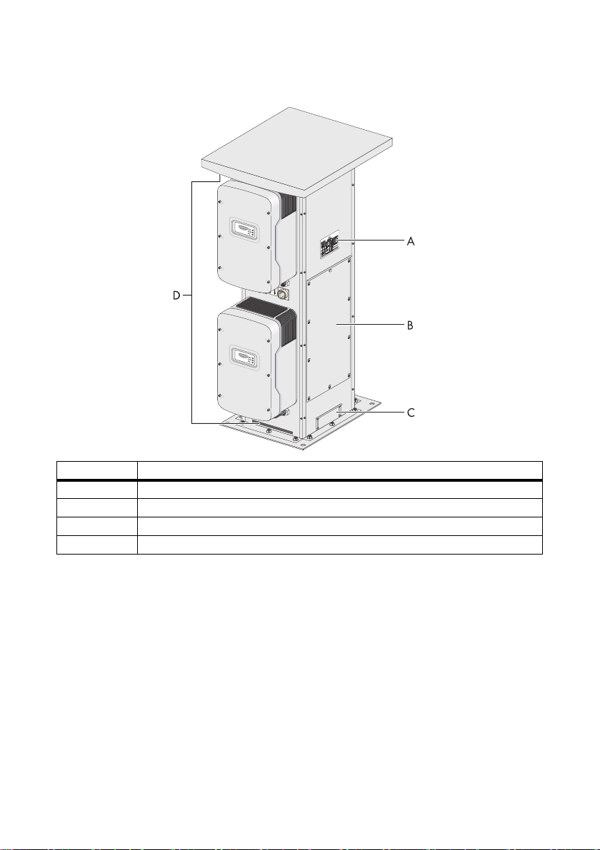
2.2 Device overview
The following figures provide you with an overview of the Sunny Tower.
Front view
Position Description
A AC/DC disconnect
BSunny Boy
10 ST36-48US-IA-IUS112321 Installation Guide
Page 11
SMA America, LLC The Sunny Tower
Rear view
Position Description
A Type plate
B Service access cover
C Conduit access/mounting plate
DAir vents
Installation Guide ST36-48US-IA-IUS112321 11
Page 12

The Sunny Tower SMA America, LLC
40.55 in.
57.24 in.
25.75 in.
27.4 in.
19.69 in.
35.07 in.
19.84 in.
71.3 in.
20.59 in.
35.07 in.
40.55 in.
2.3 Dimensions
12 ST36-48US-IA-IUS112321 Installation Guide
Page 13

SMA America, LLC The Sunny Tower
2.4 Type plate
You can identify the Sunny Tower with the type plate. The type plate is found on the back side of the
Sunny Tower.
2.5 Sunny WebBox
The Sunny WebBox is a communication option available from SMA. It enables remote
communication with the Sunny Tower.
The Sunny WebBox power supply is available in 2 voltage ranges, one version for voltages between
120 V AC and 240 V AC, the second version for 480 V AC. Verify that you have the correct version
for the utility voltage prior to commissioning the Sunny Tower.
Communication via RS485 is pre-wired as a standard feature.
Installation Guide ST36-48US-IA-IUS112321 13
Page 14

Safety SMA America, LLC
3 Safety
DANGER
Risk of electric shock due to high voltages inside the Sunny Tower.
Death or serious injuries will result.
• All work on the Sunny Tower must only be carried out by qualified personnel.
• All work on the Sunny Tower shall only be done as described in this manual.
• Pay attention to all safety instructions.
WARNING
Risk of electric shock during operation of a damaged Sunny Tower.
Death or serious injuries will result.
• The Sunny Tower may only be used when it is technically faultless and safe to
operate!
• Operate the Sunny Tower only if no damage is visibly evident!
• Visually check the Sunny Tower for damage on a regular basis!
• Ensure that all external safety features are freely accessible at all times, and that they
are regularly tested for correct functionality!
NOTICE
Electrostatic discharges possible when components are touched.
Damage to components will result.
• Follow ESD protective provisions.
• Remove existing electrostatic charges by touching a grounded metal surface (e.g.
housing).
Avoid using wire nuts to join any wires together or to make any connections anywhere in
the PV-system. Wire nuts are a frequent cause of unreliable, resistive connections, and
ground faults.
Storage of the documentation
The documentation must be kept in the immediate vicinity of the Sunny Tower. They must
be available to operators and maintenance staff at all times. Read this manual carefully.
14 ST36-48US-IA-IUS112321 Installation Guide
Page 15

SMA America, LLC Installation
4 Installation
4.1 Required tools and materials
Quantity Tool/Material Purpose
1 Hammer drill with a suitable drill bit Drilling the holes for the base plate
anchors
4 Concrete anchors with a minimum
diameter of 3/8 in.
1 Allen key 0.197 in.(5 mm) Attaching the Sunny Boy wall mount
4.2 Installing the Sunny Tower
DANGER
Danger to life due to fire or explosions.
There is always a certain risk with electric devices that a fire can occur, even though
greatest attention was paid to avoiding this during the development.
• Do not install the Sunny Tower on flammable construction materials.
• Do not install the Sunny Tower in areas where highly flammable materials are stored.
• Do not install the Sunny Tower in potentially explosive areas.
Anchor the Sunny Tower base to the
concrete pad
brackets to the Sunny Tower
The information contained in this installation guide must be observed when installing the
Sunny Tower. The inverters are designed for outdoor installation and confirm to the
protection class NEMA 3R.
The correct installation of the Sunny Tower requires:
• Proper electrical connections.
• Adequate ventilation of the inverters.
• Adequate fire prevention on site.
4.2.1 Foundation
• The foundation must guarantee solid and safe positioning of the Sunny Tower.
• The foundation must provide the necessary load-carrying capacity to cope with the weight of
the fully equipped Sunny Tower up to approximately 1,430 Ibs (649 kg).
• A foundation slab is recommended for ground-mounted installations.
Pouring and structural inspection of the foundation slab should be performed on-site.
Installation Guide ST36-48US-IA-IUS112321 15
Page 16

Installation SMA America, LLC
• When pouring the foundation, keep in mind that the cables and conduits should enter the Sunny
Tower from underneath. Therefore, suitable conduits or cable feed-throughs should be installed
prior to pouring.
4.2.2 Minimum workspace/ventilation requirements
Due to NEC 110.26 Work Space Requirements, a minimum of 36 in. (914 mm) of free space and
adequate ventilation must be maintained around all four sides of the Sunny Tower.
4.3 Installing at the site
WARNING
Risk of injury during transport of the Sunny Tower.
Injuries and contusion of body parts will result.
• Consider the weight of the Sunny Tower.
• Transport the Sunny Tower with four people or with a cart.
• Wear personal protective equipment.
• The Sunny Tower must be securely fastened to the floor before you begin with the installation
and cabling of the inverters.
• The Sunny Tower must be installed on a level surface. Any existing unevenness, depression, or
slope must be corrected prior to installation.
16 ST36-48US-IA-IUS112321 Installation Guide
Page 17
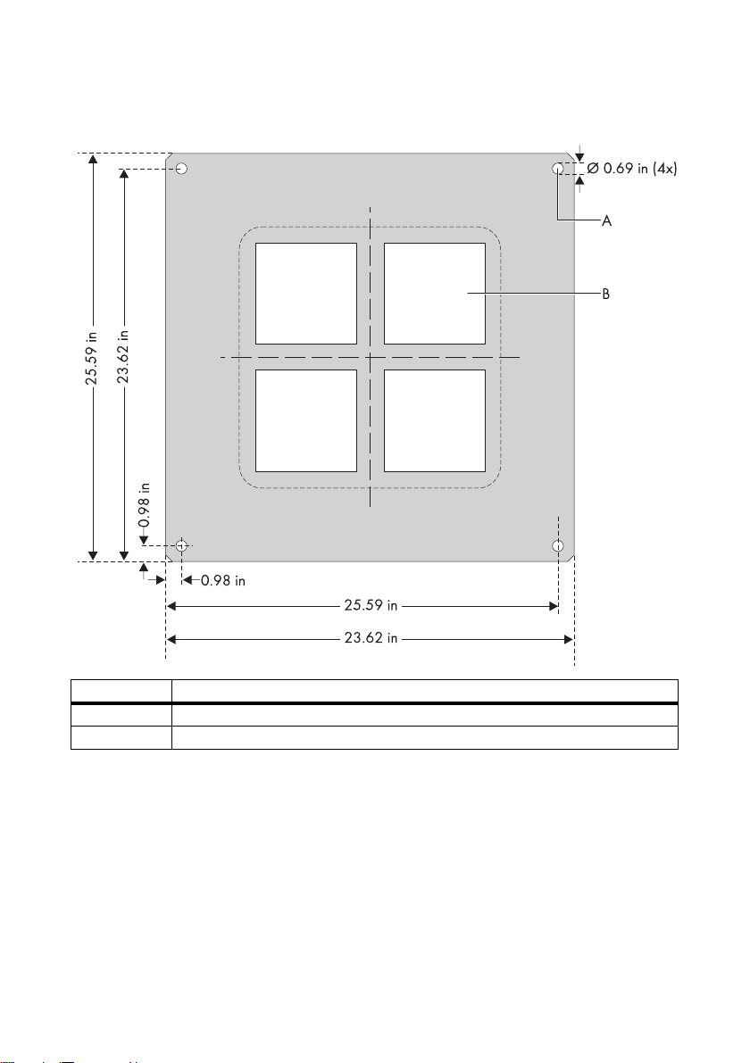
SMA America, LLC Installation
1. Mark the positions of the base plate mounting holes on the mounting surface.
Position Description
A Drill holes for the foundation connection
B Conduit openings
2. At the marked positions, drill the holes for the anchor screws.
3. Insert the concrete anchors in the drilled holes.
4. Place the Sunny Tower bottom down on the foundation. The drill holes and the base plate holes
have to align.
5. Mount the Sunny Tower to foundation using 4 scews.
☑ The Sunny Tower is installed.
6. Remove the carrying handles by unscrewing the stainless steel screws.
Installation Guide ST36-48US-IA-IUS112321 17
Page 18

Attaching the conduits SMA America, LLC
5 Attaching the conduits
This section descibes where to insert the cables in the Sunny Tower and where to punch the holes for
the conduits.
NOTICE
Moisture can seep through incorrectly installed conduits and conduit hubs.
Damage to the electronics of the Sunny Tower will result.
• For conduit hubs, use only UL listed rainproof, or wet location hubs complying with
UL 514B for entry into the enclosure.
• Adjust the diameter of the conduit hubs to match the diameter of the conduits.
The PV panel cables, the AC cables and the communication cables can be routed into the Sunny
Tower from the rear or from below. The two options are described below.
5.1 Insert cables from the rear into the Sunny Tower
1. Remove the four screws that secure the conduit
access/mounting plate to the rear of the Sunny
Tower.
2. Store the conduit access/mounting plate (3),
mounting screws and washers in a safe place while
mounting, installing or repairing the Sunny Tower.
3. Mark the holes for at least one conduit per DC
cable.
4. Mark the holes for at least one conduit per AC
cable.
5. Mark the hole for communication cable.
18 ST36-48US-IA-IUS112321 Installation Guide
Page 19

SMA America, LLC Attaching the conduits
6. Punch the holes for the conduits.
Figure to the right: Example for a plate with
conduits.
A: Conduit for AC cables.
B: Conduit for communication cables.
C: Conduit for DC cables.
7. Insert the PV-generator cables, the AC cables and
the data cables into the Sunny Tower from the rear.
A conduit access/mounting plate is attached to the
Sunny Central for this purpose.
8. Attach the plate to the Sunny Tower.
9. Attach the screws and washers and tighten with a
torque of 53inlbs (6Nm).
10. Insert the conduits into the openings.
11. Attach the conduits with the appropriate hubs.
12. Insert the cables into the Sunny Tower.
☑ The cables are inserted.
5.2 Insert cables from below into the Sunny Tower
1. Insert the following cables into the Sunny Tower from the bottom through the foundation:
– PV-Generator cables.
– AC cables.
– Data cables.
There are four openings in the base of the Sunny Tower through which the cables can be inserted into
the Sunny Tower. Two aluminum sheets are attached above the openings.
Installation Guide ST36-48US-IA-IUS112321 19
Page 20

Attaching the conduits SMA America, LLC
2. Remove the six screws that secure the aluminum
sheets to the bottom of the Sunny Tower.
3. Store the aluminum sheets, mounting screws and
washers in a safe place.
4. Place the Sunny Tower with the openings above the
cable conduits onto the base.
5. Fasten the Sunny Tower to the base as d escribed in
section 4.3 „Installing at the Location”.
6. Seal the Sunny Tower to the base.
Without
• Seal the openings down to the base.
aluminum
sheet.
With aluminum
sheet.
• Punch holes for the conduits.
Figure to the right: Example for
plates with conduits.
A: Conduit for AC cables.
B: Conduit for communication
cables.
C: Conduit for DC cables.
• Insert the conduits into the openings.
• Attach the plate to the bottom of the Sunny Tower.
• Attach the screws and washers and tighten with a torque of 53 in-lbs (6 Nm).
• Attach the conduits with the appropriate hubs.
7. Insert the cables into the Sunny Tower.
☑ The cables are inserted.
20 ST36-48US-IA-IUS112321 Installation Guide
Page 21

SMA America, LLC Opening and closing the Sunny Tower
6 Opening and closing the Sunny Tower
6.1 Opening the Sunny Tower
DANGER
Risk of electric shock due to high voltage inside the Sunny Tower.
Death and burning resulting from electric shock.
• All procedures described in this section shall only be conducted by qualified
personnel.
• Observe the sequence described here when opening the Sunny Tower.
• If problems occur when performing the work described here, contact SMA.
1. Disconnect the AC side of the Sunny Tower.
2. Disconnect the DC side of the inverters.
3. Ensure that LEDs and Display are off.
CAUTION
Components inside the Sunny Tower become hot during operation.
Danger of burn injury.
• Wait for the Sunny Tower to cool down for at least 30 minutes.
• Wear protective gloves when working on the Sunny Tower.
Installation Guide ST36-48US-IA-IUS112321 21
Page 22

Opening and closing the Sunny Tower SMA America, LLC
Opening the service access cover
1. Loosen the screws (1).
2. Remove the top middle screw of the service access cover (2). Put it aside.
3. Push the service access cover upwards (3).
4. Remove the service access cover (4).
5. Remove the grounding cable from the service access cover.
6. Store the service access cover, mounting screws and washers in a safe place while mounting,
installing or repairing the Sunny Tower.
☑ The service access cover is open.
22 ST36-48US-IA-IUS112321 Installation Guide
Page 23

SMA America, LLC Opening and closing the Sunny Tower
6.2 Closing the Sunny Tower
Closing the service access cover
1. Fit the grounding cable back to the service access cover.
2. Place the service access cover over the screws (1).
3. Push down the service access cover (2).
4. Fasten the top middle screw of the service access cover (3).
5. Tighten all screws (4).
☑ The service access cover is closed.
6.3 Opening and closing the Sunny Boy
Refer to the SB 6000US/SB 7000US/SB 8000US installation guide.
Installation Guide ST36-48US-IA-IUS112321 23
Page 24

Electrical connection SMA America, LLC
7 Electrical connection
Refer to the table below for the appropriate wire sizes and torque values.
Terminal Wire Size Wire type Torque
DC Terminal Blocks (PV-
return or PV grounded
conductors)
DC Fuse Holder (PV-hot
or PV ungrounded
conductors)
AC Terminal Blocks 350 kcmil...3/0 AWG 600 V minimum rated 194°F
Primary protective
earthing terminal
Inverter protective
earthing terminal
Cover Screws — — 53 lbsin
6...2AWG 600V minimum rated 194°F
(90°C); copper or copper clad
conductors only
14...8AWG 600V minimum rated 194°F
(90 °C); copper or copper clad
conductors only
16...10AWG 600 V minimum rated 194°F
(90 °C); copper or copper clad
conductors only
(90 °C); copper or copper clad
conductors only
2/0...1AWG 600V minimum rated 194°F
(90 °C); copper or copper clad
conductors only
6...2AWG 600V minimum rated 194°F
(90 °C); copper or copper clad
conductors only
14...8AWG 600V minimum rated 194°F
(90 °C); copper or copper clad
conductors only
2/0...2AWG 600V minimum rated 194°F
(90 °C); copper or copper clad
conductors only
6...14AWG 600V minimum rated 194°F
(90 °C); copper or copper clad
conductors only
80lbsin
(9Nm)
35 lbsin
(3.9Nm)
19 lbsin
(2.2Nm)
200 lbsin
(22.6Nm)
100 lbsin
(11.4Nm)
80 lbsin
(9Nm)
35 lbsin
(3.9Nm)
89 lbsin
(10Nm)
27 lbsin
(3Nm)
(6Nm)
24 ST36-48US-IA-IUS112321 Installation Guide
Page 25

SMA America, LLC Electrical connection
7.1 Connecting ground
The diagram below shows the equipment grounding terminals of the Sunny Tower. They are located
on the lower right side underneath the DC connections inside the SunnyTower.
• The minimum size for the primary grounding electrode conductor is 6AWG.
• The minimum size for the individual inverter grounding electrode conductors is 8AWG.
Installation Guide ST36-48US-IA-IUS112321 25
Page 26

Electrical connection SMA America, LLC
7.2 Grid configuration
Configurate the AC fuses inside of the Sunny Tower to use different grid types for the Sunny Tower.
Refer to the yellow labels which are directly located on the AC fuse holders for detail information.
Configurate the Sunny Boys as described in the Sunny Boy installation guide.
The following figures show possible grid configurations for the Sunny Tower.
208 V WYE, available for ST36 and ST42
240 V Delta, available for ST36, ST42 and ST48
26 ST36-48US-IA-IUS112321 Installation Guide
Page 27

SMA America, LLC Electrical connection
480 V WYE, available for ST36, ST42 and ST48
Installation Guide ST36-48US-IA-IUS112321 27
Page 28

Electrical connection SMA America, LLC
7.3 Connecting the AC output
AC Fuse
When inserting the fuses provided with the ST36/ST42/ST48 you must consider the local
grid configuration and voltage! If the Sunny Tower is to be used in a 480/277 volt
installation, the fuses for the L2 connections of each inverter must not be installed. These
fuse holders are marked with yellow warning labels on the fuse holders inside the Sunny
Tower.
Maximum Inverter AC output fuse size is 50 A, Fuse must be fast acting Class J
(forexample: Ferraz A4J50, Bussman JKS-50, Littelfuse JLS-50).
Ensure that the Sunny Tower is properly grounded and the bonding of your equipment is
in accordance with NEC articles 250 and 690.
AC-output/neutral is not bonded to ground!
1. Turn OFF the main breaker in the main utility box.
2. Ensure that the correct breaker sizes specified in the table below are installed.
Inverter Type Grid Configuration Breaker Size
SB 8000US 480 V/277 V 80 A
SB 8000US 240 V 150 A
SB 7000US 480 V/277 V 70 A
SB 7000US 208 V/120 V 150 A
SB 7000US 240 V 150 A
SB 6000US 480 V/277 V 60 A
SB 6000US 208 V/120 V 125 A
SB 6000US 240 V 110 A
Ensure that conductors are sized in accordance with NEC article 310.
28 ST36-48US-IA-IUS112321 Installation Guide
Page 29

SMA America, LLC Electrical connection
The inscription goes from left to right.
Position Description
Ø Connection terminal for the grid connection to XA (L1)
Ø Connection terminal for the grid connection to XB (L2)
Ø Connection terminal for the grid connection to XC (L3)
N Connection terminal for the grid connection to N (neutral)
Installation Guide ST36-48US-IA-IUS112321 29
Page 30

Electrical connection SMA America, LLC
7.4 Connecting the DC Input
DANGER
Voltage is present in PV-modules exposed to light.
Risk of electric shock when touching the DC cable attached to a PV-module.
Death and burn injuries will result.
• Cover the PV-modules with opaque material.
• Follow all safety precautions of the module manufacturer.
Make sure that your cable has sufficient length.
1. Open the fuse switch of each individual safety device.
PV array wiring can enter the tower enclosure from below or through the cable access
cover. If necessary use an appropriate knock out punch to create knockouts for the array
conduits.
2. Connect the PV array wiring to the string fuse holders as shown below.
PV str ing con duc tor s sh ould be su ppo rte d us ing the cab le t ie t abs near the inputs of the fuse
holders and terminal blocks.
30 ST36-48US-IA-IUS112321 Installation Guide
Page 31

SMA America, LLC Electrical connection
Position Installed Sunny Boy PV Connection
A Sunny Boy 1 PV return
B Sunny Boy 1 PV hot
C Sunny Boy 2 PV return
D Sunny Boy 2 PV hot
E Sunny Boy 3 PV return
F Sunny Boy 3 PV hot
G Sunny Boy 4 PV hot
H Sunny Boy 4 PV return
I Sunny Boy 5 PV hot
K Sunny Boy 5 PV return
L Sunny Boy 6 PV hot
M Sunny Boy 6 PV return
3. PV hot (PV ungrounded) conductors should be connected to the fuse holders.
PV return (PV grounded) conductors should be connected to the associated terminal blocks.
Installation Guide ST36-48US-IA-IUS112321 31
Page 32

Electrical connection SMA America, LLC
DC Fuse
The maximum allowable fuse size for the DC string fuses is 20A. Fuse must be fast acting.
Fuses are provided with the Sunny Tower. The proper size PV string fuse is determined by
1.56 x Isc (of the PV module) and then rounding up to the next standard fuse size.
Example: If the Isc of the PV module = 6.9 Adc then the fuse size is determined by
1.56x6.9=10.76. The next standard fuse size would be 12A, 600Vdc fuse.
The string fuse size must not be greater than the maximum fuse size rating of the PV mo dule.
7.5 Installing the inverters on the Sunny Tower
The Sunny Tower must be securely fastened to the floor prior to installing and connecting
the inverters.
Installing the mounting brackets (A) for the Sunny Boy
1. Hold the mounting bracket (A) over the corresponding screw anchor holes of the Sunny Tower.
2. Fasten the mounting bracket (A) using the metric threaded stainless steel screws (M8x16mm
with corresponding locking washers) provided with the Sunny Tower.
3. Perform these steps again for installing the remaining mounting brackets.
4. Refer to the SB 6000US/SB 7000US/SB 8000US manual for further installation instructions.
32 ST36-48US-IA-IUS112321 Installation Guide
Page 33

SMA America, LLC Electrical connection
7.6 Wiring Connections to the Sunny Boy
The AC and DC system cables are already pre-wired to the inverter mounting locations of the Sunny
Tower.
Position Description
ADC cable
BAC cable
CAC/DC Disconnect
D Communicaton cable
In addition to this manual, refer to the SB 6000US/SB 7000US/SB 8000US manual for instructions
on wiring the AC and DC cables inside the inverters and configuring the AC voltage of the inverter.
Information on this subject can be read in the appropriate section.
The AC/DC disconnect serves to simultaneously disconnect the AC and DC connections.
The DC inp ut and AC output circ uits are isolated from the enclosure and system grounding.
If an alternative grounding scheme is required, it is the responsibility of the installer.
The PV-system grounding shall be installed per the requirements of sections 690.41
through 690.47 of the National Electric Code, ANSI/NFPA 70, and is the responsibility
of the installer.
The National Electrical Code, ANSI/NFPA 70, wiring methods are to be used.
Installation Guide ST36-48US-IA-IUS112321 33
Page 34

Electrical connection SMA America, LLC
Appropriate torque values and wire sizes
Terminal Nm inIbs Wire Size
AC & DC Terminal Blocks 2 18 10...6AWG
Unused Terminal Block for
AC Configuration
Cover Screws 6 53 —
1.3 11 —
7.6.1 AC Wiring of the SB 6000US/SB 7000US/SB 8000US
DANGER
High voltages are present on the AC and DC cables. Risk of electric shock.
Death or serious injuries will result when touching voltage-conducting cables and contacts.
• All procedures described in this section shall only be conducted by qualified
personnel.
• Observe the sequence described here when opening the Sunny Boy.
Routing the AC cable into the Sunny Boy
1. Refer to the Sunny Boy installation guide for opening the Sunny Boy.
2. Remove a membrane at the bottom of the inverter.
3. Pull the cable conduit from below into the Sunny
Boy.
4. Tighten the conduit with the locknut from the inside
of the inverter.
34 ST36-48US-IA-IUS112321 Installation Guide
Page 35

SMA America, LLC Electrical connection
AC wiring for 208 V/240 V grid configuration
1. Connect the white wire of the AC/DC disconnect to the terminal labeled N and the black wire
to the terminal labeled L1 of the Sunny Boy.
2. connect the blue wire to the terminal labeled L2 in the Sunny Boy.
Position Description
A Black wire connected to L1 terminal
B Blue wire connected to L2 terminal
C White wire connected to N terminal
3. Connect the wires to the terminal blocks in the Sunny Boy and tighten to a torque of 18inlb
(2Nm).
4. Verify that all connections are correctly wired and properly torqued.
☑ The Sunny Boy is connected to the 208V/240V grid.
5. Repeat steps 1 to 4 for the AC wiring of the remaining Sunny Boy inverters.
Installation Guide ST36-48US-IA-IUS112321 35
Page 36

Electrical connection SMA America, LLC
AC wiring for 277V/480V grid configuration
1. Connect the white wire of the AC/DC disconnect to the terminal labeled N and the black wire
to the terminal labeled L1 of the Sunny Boy.
2. For 277V/480V connect the blue wire to the terminal labeled PE in the Sunny Boy (not used).
Position Description
A Blue wire connected to PE terminal
B Black wire connected to L1 terminal
C White wire connected to N terminal
3. Connect the wires to the terminal blocks in the Sunny Boy and tighten to a torque of 18inlb
(2Nm).
4. Verify that all connections are correctly wired and properly torqued.
☑ The Sunny Boy is connected to the 277V/480V grid.
5. Repeat steps 1 to 4 for the AC wiring of the remaining Sunny Boy inverters.
36 ST36-48US-IA-IUS112321 Installation Guide
Page 37

SMA America, LLC Electrical connection
7.6.2 DC wiring of the SB 6000US/SB 7000US/SB 8000US
The Sunny Boy is configured for negative ground systems. Certain types of PV modules may require
that the positive terminal be grounded instead of the negative terminal. To configure the Sunny Boy
for positive ground, move the fuse (1) and change the jumper position (2) as shown in the following
illustrations.
Negative grounding
Following figure shows GFDI Fuse and Jumper Settings for negative grounding.
Positive grounding
Following figure shows GFDI Fuse and Jumper Settings for positive grounding.
Installation Guide ST36-48US-IA-IUS112321 37
Page 38

Electrical connection SMA America, LLC
Routing the DC cable into the Sunny Boy
1. Refer to the Sunny Boy installation guide for opening the Sunny Boy.
2. Remove a membrane at the bottom of the inverter.
3. Pull the cable conduit from below into the Sunny
Boy.
4. Tighten the conduit with the locknut from the inside
of the inverter.
38 ST36-48US-IA-IUS112321 Installation Guide
Page 39

SMA America, LLC Electrical connection
Negative grounding
Following figure shows the DC connection with negative grounding.
Position Description
A White wire (PV RETURN) connected to DC −
B Black wire (PV HOT) connected to DC+
1. Connect the black wire (PV HOT) to the terminal labeled DC+ in the Sunny Boy.
2. Connect the white wire (PV RETURN) to the terminal labeled DC − in the Sunny Boy.
3. Torque all wires in the terminal blocks inside the Sunny Boy to 18inlb (2Nm).
4. Verify that all connections are correctly wired and properly torqued.
☑ The Sunny Boy is DC wired with negative grounding.
5. Repeat steps 1 to 4 for DC wiring with negative grounding for the remaining Sunny Boy
inverters.
Installation Guide ST36-48US-IA-IUS112321 39
Page 40

Electrical connection SMA America, LLC
Positive grounding
Following figure shows the DC connection with positive grounding.
Position Description
A White wire (PV RETURN) connected to DC+
B Black wire (PV HOT) connected to DC −
Avoid using wire nuts to join any wires together or to make any connections anywhere in
the PV system. Wire nuts are a frequent cause of unreliable connections, resistive
connections, and ground faults.
1. Connect the white wire (PV RETURN) to the terminal labeled DC+ in the Sunny Boy.
2. Connect the black wire (PV HOT) to the terminal labeled DC − in the Sunny Boy.
3. Torque all wires in the terminal blocks inside the Sunny Boy to 18inlb (2Nm).
4. Verify that all connections are correctly wired and properly torqued.
☑ The Sunny Boy is DC wired with positive grounding.
5. Repeat steps 1 to 4 for DC wiring with negative grounding for the remaining Sunny Boy
inverters.
40 ST36-48US-IA-IUS112321 Installation Guide
Page 41

SMA America, LLC Communication
8 Communication
The communication cables must be wired in separate conduits or raceways and must be
isolated from the power lines!
For detail information on communication, refer to the SB 6000US/SB 7000US/SB 8000US and the
Sunny WebBox installation guide.
• If ordered, the Sunny WebBox is already installed inside the Sunny Tower.
• Connec t the communication cables to each installed Sunny Boy. Connect other bus participants
to the communication distributor.
• The communication distributor is situated inside the Sunny Tower.
8.1 External communication device
To connect an external communication device to the communication bus of the Sunny Tower simply
connect the RS485 cable to the RJ45 socket as you can see below.
Position Description
A Socket for external communication device
B Socket for additional bus participant or termination resistor
Installation Guide ST36-48US-IA-IUS112321 41
Page 42

Communication SMA America, LLC
8.2 Communication interface 485USPB-NR or 485USPB-SMC-NR
For installing the communication interface 485USPB-NR or 485USPB-SMC-NR refer to the
appropriate installation guide.
Position Description
A Cable routing
B Male connector for PE
C Openings for communication cabling conduits
D Screw terminals for connecting the communication cabling
EJumper slot
FInterface slot
Signal Conductor color Screw terminal of the inverter (D)
Data+ White, green 2
Data − Brown, yellow 7
GND Grey 5
42 ST36-48US-IA-IUS112321 Installation Guide
Page 43

SMA America, LLC Communication
screen
1
8
8.3 External communication device
To connect an external communication device to the communication bus of the Sunny Tower simply
connect the RS485 cable to the RJ45 socket as you can see below.
Position Description
A Socket for additional bus participant or termination resistor
B External communication device
Pin configuration from RJ45-plug:
PIN 1= Data PIN 2= GND
PIN 3= Data +
Installation Guide ST36-48US-IA-IUS112321 43
Page 44

Communication SMA America, LLC
8.4 Connecting another Sunny Tower
44 ST36-48US-IA-IUS112321 Installation Guide
Page 45

SMA America, LLC Communication
Position Description
A RJ45 socket for Sunny WebBox or external communication device
B Connection to next Sunny Tower
C Termination resistor location
1. Remove and save the bus termination resistor in the first Sunny Tower.
2. Connect a patch cable (RJ45 plug) to the place of the removed bus termination resistor.
3. Route the cable to the second Sunny Tower.
4. In the second Sunny Tower place the bus termination resistor in the appropriate RJ45 socket, if
not already present.
Installation Guide ST36-48US-IA-IUS112321 45
Page 46

Communication SMA America, LLC
8.5 Installing the Sunny WebBox
The connection of the communication cable to the Sunny Boy is described in detail in the
installation guide of the Sunny Boy and the communication device.
• Refer to the appropriate section of these manuals.
The optional Sunny WebBox is installed inside of the Sunny Tower.
The communication cables from the WebBox to each Sunny Boy are already pre-installed.
Proceed as follows:
1. Remove the clear cover of the WebBox housing.
2. Remove the square plug of the cable entry in the WebBox housing.
3. Place the square plug over the Ethernet cable.
4. Insert the square plug with the Ethernet cable into the cable entry of the WebBox housing.
5. Attach the Ethernet cable to the WebBox.
6. Install the clear cover on the WebBox housing.
Route the Ethernet cable parallel to the communication lines, further into the right front corner, then
downward to the cable entry of the Sunny Towers.
46 ST36-48US-IA-IUS112321 Installation Guide
Page 47

SMA America, LLC Communication
Sunny WebBox 120V...240V version
Position Description
A AC cable to Sunny Tower
B RS485 cable to communication distribution
Installation Guide ST36-48US-IA-IUS112321 47
Page 48

Communication SMA America, LLC
Sunny WebBox 480V version
Position Description
A AC cable to Sunny Tower
B RS485 cable to communication distribution
48 ST36-48US-IA-IUS112321 Installation Guide
Page 49

SMA America, LLC Commissioning the Sunny Tower
9 Commissioning the Sunny Tower
Requirements for the initial start-up
NOTICE
Risk of overvoltage.
Damage to connected PV-modules and fuses will result.
• Ensure the correct polarity of each DC cable connected to the Sunny Tower.
• Ensure the correct DC fuse size regarding the grid configuration.
1. Check the AC main connection inside the Sunny Tower for a clockwise rotating field.
– Use a rotating field instrument for checking.
2. Proceed with commissioning the Sunny Tower only after:
– The housing covers on the SB 6000US/SB 7000US/SB 8000US inverters are closed.
– The DC cables are connected correctly.
– The AC cable is connected correctly.
– All conduit fittings are secured.
3. Verify the functionality of the AC/DC disconnect. Operate each AC/DC disconnect for
10times as follows:
– Turn from position “0“ (off) to position “1“ (on).
– Turn back from position “1“ (on) to position “0“ (off).
4. Switch on the breaker of the AC distribution panel, connecting the Sunny Tower to the grid.
5. Verify the correct voltage range at the grid connection terminals, 208V, 240V or 277V/
480V. See section 7.2 for details.
Installation Guide ST36-48US-IA-IUS112321 49
Page 50

Commissioning the Sunny Tower SMA America, LLC
Inserting the fuses for 208V/240V grid configuration
1. Turn each AC/DC disconnector to "0" (off).
2. If the Sunny Tower is to be used in a 208V/240V installation insert both fuses.
3. Ensure that all DC string fuse holders are closed.
Inserting the fuses for 277V/480V grid configuration
When inserting the fuses provided with the Sunny Tower, you must consider the local grid
configuration and voltage! If the Sunny Tower is to be used in a 277V/480V installation,
the fuses for the L2 connections of each inverter must not be installed. These fuse holders
are marked with yellow warning labels on the fuse holders inside the Sunny Tower.
Maximum Inverter AC output fuse size is 50A, Fuse must be fast acting Class J (for
example: Ferraz A4J50, Bussman JKS-50, Littelfuse JLS-50).
1. Turn each AC/DC disconnector to "0" (off).
2. If the Sunny Tower is to be used in a 277V/480V installation insert one fuse only.
3. Ensure that all DC string fuse holders are closed.
T
The maximum allowable fuse size for the DC string fuses is 15 amps. Fuse must be fast
acting (for example: Ferraz ATM15, Bussman KTK15, Littelfuse KLK15).
50 ST36-48US-IA-IUS112321 Installation Guide
Page 51

SMA America, LLC Commissioning the Sunny Tower
Closing the service access cover and starting the Sunny Tower
1. Fit the grounding cable back to the service access cover.
2. Place the service access cover over the screws (1).
3. Push down the service access cover (2).
4. Fasten the top middle screw of the service access cover (3).
5. Tighten all screws (4).
☑ The service access cover ist installed.
6. One after another switch on the AC/DC disconnector of each Sunny Boy to "1" (on).
7. Check the green LED on each Sunny Boy, to ensure that each one is operating correctly.
If the Sunny Boy displays other messages or blink codes, refer to the SB 6000US/
SB7000US/SB 8000US manual for trouble shooting information.
Installation Guide ST36-48US-IA-IUS112321 51
Page 52

Cleaning and maintenance SMA America, LLC
10 Cleaning and maintenance
Remove dirt and dust from the air vents (A) of the Sunny Tower once a year. If the Sunny Tower is
operated in areas with a high amount of dust or dirt check the air vents for dirt more frequently.
• Use vacuum cleaner for cleaning the air vents.
• Additionally use a soft brush in order to loosen the dust or dirt.
• Make sure that no loose dust or dirt gets inside the Sunny Tower.
To ensure the proper operation of the SunnyTower operate each AC/DC disconnect at least once a
year for 10times as follows:
1. Turn from position “0“ (off) to position “1“ (on).
2. Turn back from position “1“ (on) to position “0“ (off).
3. Repeat steps 1 and 2 with the remaining AC/DC disconnectors.
52 ST36-48US-IA-IUS112321 Installation Guide
Page 53

SMA America, LLC Technical data
11 Technical data
11.1 Sunny Tower ST36 equipped with Sunny Boy SB 6000US
PV generator connection
Recommended Maximum PV Power
(ModuleSTC)
DC Maximum Voltage 600V
Peak Power Tracking Voltage 250V...480V
DC Maximum Input Current 150A
Number of Fused String Inputs
(AC‑DCdisconnect)
Fuse Size 15A
PV Start Voltage (Adjustable) 300V
Power Factor (Nominal) 0.99
45 kW
24
Grid connection
AC Nominal Power 36.0kW
AC Maximum Power 36.0kW
AC Maximum Output Current at 208 V
(3‑PhaseOnly)
AC Maximum Output Current at 240 V
(3‑PhaseOnly)
AC Maximum Output Current at 277 V
(3‑PhaseOnly)
AC Nominal Voltage Range at 208 V Delta or
WYE (3‑PhaseOnly)
AC Nominal Voltage Range at 240 V Delta
(3‑PhaseOnly)
AC Nominal Voltage Range at 277 V WYE
(3‑PhaseOnly)
AC Frequency Nominal 60Hz
AC Frequency Range 59.3Hz...60.5Hz
Power consumption at night 0.6W
100A
87A
44A
187V...229V
211V...264V
244V...305V
Efficiency
Peak Inverter Efficiency 97.0%
CEC Weighted Efficiency at 208 V/240 V 95.5%
CEC Weighted Efficiency at 277 V 96.0%
Installation Guide ST36-48US-IA-IUS112321 53
Page 54

Technical data SMA America, LLC
Ambient conditions
Ambient Temperature Range − 13°F...+113°F
( − 25°C...+45°C)
Mechanical data
WidthxHeightxDepth 43.3inx70.5inx39in
(1.100mmx1.791mmx991mm)
Tower Weight 330lbs(150kg)
6 Inverters Weight 846lbs(384kg)
Total Shipping Weight 1.388lbs(630kg)
Features
Topology LF transformer
Sunny Boy coolingconcept OptiCool ™ , forced active cooling
RS485 communication yes
Wireless communication optional
LCD display yes
54 ST36-48US-IA-IUS112321 Installation Guide
Page 55

SMA America, LLC Technical data
11.2 Sunny Tower ST42 equipped with Sunny Boy SB 7000US
PV generator connection
Recommended Maximum PV Power
(ModuleSTC)
DC Maximum Voltage 600V
Peak Power Tracking Voltage 250V...480V
DC Maximum Input Current 180A
Number of Fused String Inputs
(AC‑DCdisconnect)
PV Start Voltage (Adjustable) 300V
Power Factor (Nominal) 0.99
52.5 kW
24
Grid connection
AC Nominal Power 42.0kW
AC Maximum Power 42.0kW
AC Maximum Output Current at 208 V
(3‑PhaseOnly)
AC Maximum Output Current at 240 V
(3‑PhaseOnly)
AC Maximum Output Current at 277 V
(3‑PhaseOnly)
AC Nominal Voltage Range at 208 V Delta or
WYE (3‑PhaseOnly)
AC Nominal Voltage Range at 240 V Delta
(3‑PhaseOnly)
AC Nominal Voltage Range at 277 V WYE
(3‑PhaseOnly)
AC Frequency Nominal 60Hz
AC Frequency Range 59.3Hz...60.5Hz
Power consumption at night 0.6W
117A
101A
51A
187V...229V
211V...264V
244V...305V
Efficiency
Peak Inverter Efficiency 97.1%
CEC Weighted Efficiency at 208 V 95.5%
CEC Weighted Efficiency at 240 V/277 V 96.0%
Ambient conditions
Ambient Temperature Range − 13°F...+113°F
( − 25°C...+45°C)
Installation Guide ST36-48US-IA-IUS112321 55
Page 56

Technical data SMA America, LLC
Mechanical data
WidthxHeightxDepth 43.3inx70.5inx39in
(1.100mmx1.791mmx991mm)
Tower Weight 330lbs(150kg)
6 Inverters Weight 846lbs(384kg)
Total Shipping Weight 1.388lbs(630kg)
Features
Topology LF transformer
Sunny Boy cooling concept OptiCool ™ , forced active cooling
RS485 communication yes
Wireless communication optional
LCD display yes
56 ST36-48US-IA-IUS112321 Installation Guide
Page 57

SMA America, LLC Technical data
11.3 Sunny Tower ST48 equipped with Sunny Boy SB 8000US
PV generator connection
Recommended Maximum PV Power
(ModuleSTC)
DC Maximum Voltage 600V
Peak Power Tracking Voltage 300V ...480V
DC Maximum Input Current 180A
Number of Fused String Inputs
(AC‑DCdisconnect)
PV Start Voltage (Adjustable) 365V
Power Factor (Nominal) 0.99
60kW
24
Grid connection
AC Nominal Power 48.0kW
AC Maximum Power 48.0kW
AC Maximum Output Current at 208 V
(3‑PhaseOnly)
AC Maximum Output Current at 240 V
(3‑PhaseOnly)
AC Maximum Output Current at 277 V
(3‑PhaseOnly)
AC Nominal Voltage Range at 208 V Delta or
WYE (3‑PhaseOnly)
AC Nominal Voltage Range at 240 V Delta
(3‑PhaseOnly)
AC Nominal Voltage Range at 277 V WYE
(3‑PhaseOnly)
AC Frequency Nominal 60Hz
AC Frequency Range 59.3Hz...60.5Hz
Power consumption at night 0.6W
N/A
116A
58A
N/A
211V...264V
244V...305V
Efficiency
Peak Inverter Efficiency 96.5%
CEC Weighted Efficiency at 208 V N/A
CEC Weighted Efficiency at 240 V/277 V 96.0%
Ambient conditions
Ambient Temperature Range − 13°F...+113°F
( − 25°C...+45°C)
Installation Guide ST36-48US-IA-IUS112321 57
Page 58

Technical data SMA America, LLC
Mechanical data
WidthxHeightxDepth 43.3inx70.5inx39in
(1.100mmx1.791mmx991mm)
Tower Weight 330lbs(150kg)
6 Inverters Weight 888lbs(403 kg)
Total Shipping Weight 1.430lbs(649kg)
Features
Topology LF transformer
Sunny Boy cooling concept OptiCool ™ , forced active cooling
RS485 communication yes
Wireless communication optional
LCD display yes
58 ST36-48US-IA-IUS112321 Installation Guide
Page 59

SMA America, LLC Contact
12 Contact
If you have technical problems concerning our products, contact the SMA Serviceline. We require the
following information in order to provide you with the necessary assistance:
• Serial number of the Sunny Tower.
• Type of inverters connected to the Sunny Tower.
• Serial numbers of the inverters connected to the Sunny Tower.
• Type and number of PV-modules connected to the Sunny Tower.
• Communication devices connected to the Sunny Tower.
• Blink codes or display messages of the connected inverters.
•Communication method.
SMA Solar Technology America, LLC
6020 West Oaks Blvd, Ste 300
Rocklin, CA 95765
Tel. +1 916 625 0870
Tel. +1 877-MY SMA TECH
Tel. +1 877 697 6283 (Toll free, available for USA, Canada and Puerto Rico)
Fax +1 916 625 0871
Service@SMA-America.com
www.SMA-America.com
SMA Solar Technology Canada Inc.
2425 Matheson Blvd E, 8th Floor
Mississauga, ON L4W 5K5, Canada
Tel. +1 877 506 1756 (Toll free, available for Canada)
Service@SMA-Canada.ca
www.SMA-Canada.ca
Installation Guide ST36-48US-IA-IUS112321 59
Page 60

4.""NFSJDB--$
XXX4.""NFSJDBDPN
 Loading...