

Page 1
TechnicalInformation
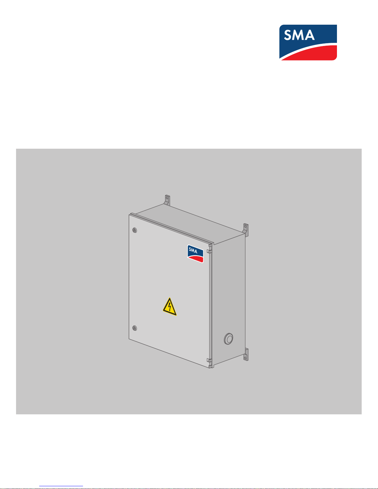
SMA STRING-MONITOR SSM-U-XX10 / SSM-U-XX15
SSMUXX1015-TI-en-10 | Version 1.0
ENGLISH
Page 2

1 Overview of Product Details
Product Description
• The SMA String-Monitor is a PV array junction box for outdoor areas to which several strings can be connected in
parallel. The SMAString-Monitor collects, measures and monitors the input currents of the strings, assists in
detecting failures, thus helping to minimize power and yield losses.
• The measured values are transmitted from the SMA String-Monitor via Ethernet to the next SMA String-Monitor in
the communication bus up to the inverter. Distances of up to 100m between the nodes are possible when using
copper cables. Greater distances of up to 2,000 m between two nodes are possible via optical fibers (see
Section8, page24).
• The number of SMA String-Monitors connectable to an inverter depends on the DC inputs of the inverter. One
SMA String-Monitor per DC input can be connected to the inverter.
• Up to ten SMA String-Monitors can be connected in line topology to each string monitoring communication
terminal of the inverter (for information on the number of string monitoring communication terminals, see the
inverter manual).
• The SMAString-Monitor is equipped with a DC load-break switch. The DC load-break switch can disconnect the
PV array connected to the SMA String-Monitor from the inverter.
• The SMA String-Monitor may only be operated if the strings are protected with fuses. SMA Solar Technology AG
guarantees the safe operation of the SMA String-Monitors in combination with inline fuse connectors as string
fuses and when the inline fuse connectors are connected directly to the DC connectors of the string cables of the
SMA String-Monitor. Using a different type and location of fuses for the strings does not guarantee the safe
operation of the SMA String-Monitor and the observance of the thresholds by SMA Solar Technology AG. The
inline fuse connectors are available as an accessory (see Section8, page24).
• There are six SMA String-Monitor models available depending on the system voltage and on the number of PV
inputs to be monitored:
– The SSM-U-XX10 is suitable for voltages of up to 1,000 VDC and is available with XX = 16, 24 or 32 PV
inputs.
– The SSM-U-XX15 is suitable for voltages of up to 1,500 VDC and is available with XX= 16, 24 or 32 PV
inputs.
Equipment and Equipment Options
• Depending on the product option, the SMA String-Monitor is equipped with 16, 24 or 32 measuring channels.
Different numbers of string inputs and string fuses can be assigned to the measuring channels. This allows you to
achieve the optimum design for your PV system and to protect the PV array from reverse currents.
• The interior of the SMA String-Monitor is equipped with protective covers for the lower DC input area and for the
upper DC output area. This facilitates working on the disconnected lower DC input area in the SMA StringMonitor without having to disconnect the DC output area from voltage sources on the inverter side.
• The string fuses are attached on the outside of the enclosure of the SMA String-Monitor. This prevents additional
heat in the enclosure caused by the waste heat of the string fuses.
Inline fuse connectors of the SUNCLIX plug-in system by Phoenix Contact with internal gPV fuse are available as
an accessory. The inline fuse connectors are connected to the pre-installed DC connectors of the string cables of
the SMA String-Monitor.
The inline fuse connectors can be connected to the positive and/or negative terminal of the PV inputs and are
available in different electrical current strengths.
• The SMA String‑Monitor is equipped with a type II overvoltage protection. This protects the inverter against
overvoltage. The SMA String-Monitor can be additionally equipped with a type II overvoltage protection for the
communication connection and for the 230 VAC voltage supply of the SMA String-Monitor.
1 Overview of Product Details
SMA Solar Technology AG
Technical InformationSSMUXX1015-TI-en-102
Page 3

• The SMAString-Monitor is equipped with a double-bit key for the switch cabinet. Profile half-cylinders are
available upon request from the manufacturer of the SMA String-Monitor enclosure.
• DC connection:
– You can connect up to two DC main cables per terminal by default.
– You can connect DC main cables from 70 mm2 to 400 mm2 made of aluminum or copper to the busbar in
the SMA String-Monitor by means of terminal lugs. Only tin-plated copper tube terminal lugs for copper
cables or bimetal tube terminal lugs for aluminum cables are permitted.
– You can connect DC main cables from 70 mm2 to 300 mm2 made of aluminum or copper to the V-box
terminals in the SMA String-Monitor. The V-box terminals are available as an accessory.
– For connecting the tube terminal lugs or the V-box terminals, the required material for the bolted connection is
pre-mounted on the busbars.
• DC load-break switch:
– The DC load-break switch is equipped with a viewing window for the contacts.
– To receive feedback on the switching state of the DC load-break switch, an alarm contact is available as an
accessory (see Section8, page24).
1 Overview of Product Details
SMA Solar Technology AG
Technical Information 3SSMUXX1015-TI-en-10
Page 4
2 Product Description
2.1 Circuitry Options with Inline String Fuses
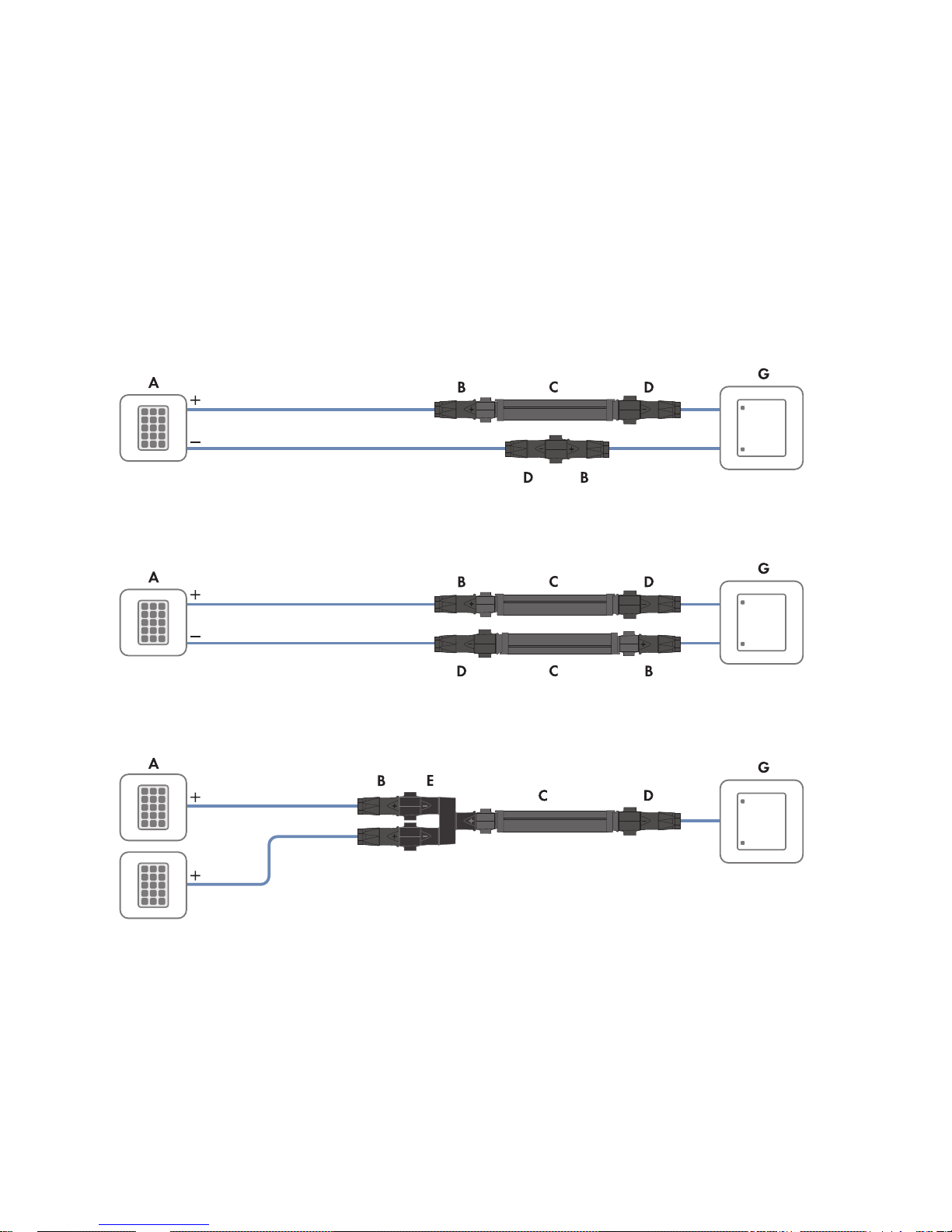
The string fuses for the SMA String-Monitor are integrated as so-called "inline string fuses" on the outside of the
enclosure in the string connection. The string terminals of the SMA String-Monitor are equipped with DC connectors
from the SUNCLIX product range of Phoenix Contact. Suitable for the SUNCLIX plug-in system, inline fuse connectors
(see Section2.2, page6) and Y adapters are available from SMA Solar Technology AG as accessories (see
Section8, page24).
The string terminals are located outside of the enclosure of the SMA String-Monitor. This offers several options for the
circuitry and fuse protection of the strings.
One-Sided Fuse Protection with Inline Fuse Connector on the Positive or Negative Terminal
Figure 1: One-sided fuse protection with inline fuse connector on the positive terminal (example)
Two-Sided Fuse Protection with Inline Fuse Connector on the Positive or Negative Terminal
Figure 2: Two-sided fuse protection with inline fuse connector on the positive or negative terminal (example)
Two Strings on One Fuse via Y Adapter
Figure 3: Two strings on one fuse via Y adapter (example)
2 Product Description
SMA Solar Technology AG
Technical InformationSSMUXX1015-TI-en-104
Page 5
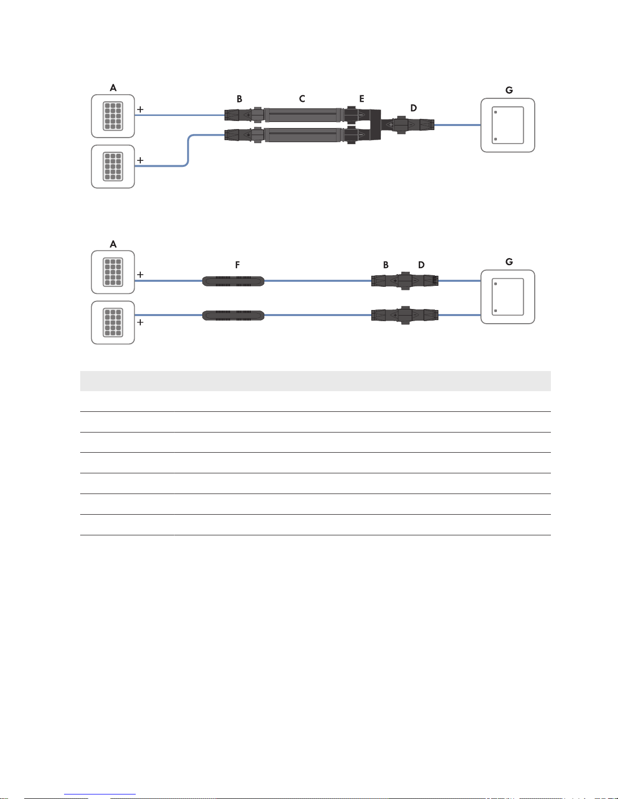
Two Fuses on One String via Y Adapter
Figure 4: Two fuses on one string via Y adapter (example)
Connection of Pre-Fabricated Cable Harnesses with Integrated String Fuse
Figure 5: Connection of pre-fabricated cable harnesses with integrated string fuse (example)
Position Designation
A PV module
B DC connector (positive terminal)
C Inline fuse connector
D DC connector (negative terminal)
E Y adapter
F Integrated string fuse
G SMA String-Monitor
2 Product Description
SMA Solar Technology AG
Technical Information 5SSMUXX1015-TI-en-10
Page 6
2.2 Inline Fuse Connector as Inline String Fuse
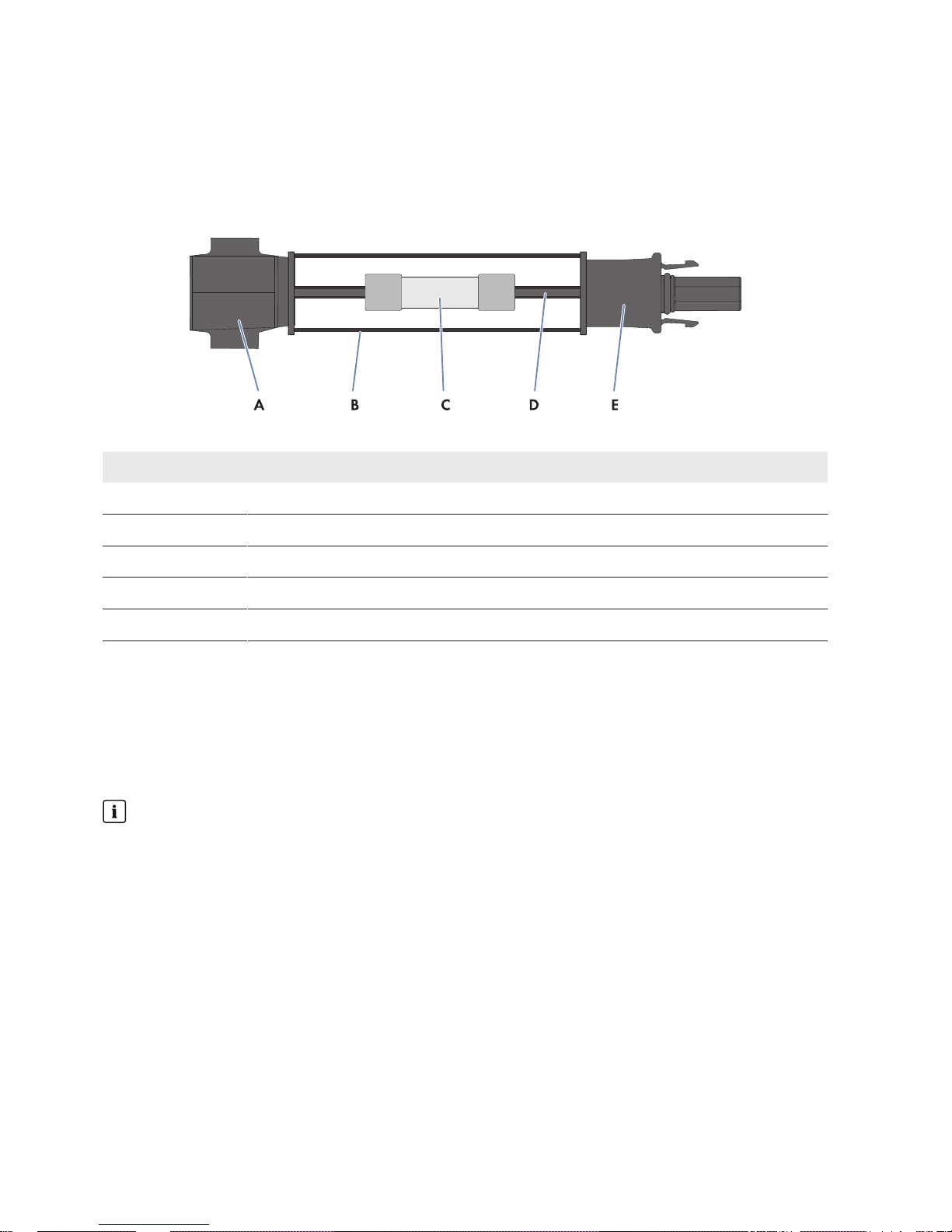
The DC connectors and the inline fuse connectors are from the SUNCLIX plug-in system by Phoenix Contact and can
be installed by easily plugging them together. For further information on this subject, see the Technical Information
"IFCON Inline Fuse Connector Set16".
Design of the Inline Fuse Connector by Phoenix Contact
Figure 6: Design of the inline fuse connector by Phoenix Contact
Position Designation
A Plug-in contact (pin) from the SUNCLIX plug-in system
B Enclosure
C Electronic string fuse
D Connection of the plug-in contact with the fuse
E Plug-in contact (pin connector) from the SUNCLIX plug-in system
2.3 DC Load-Break Switch
The SMAString-Monitor is equipped with a multi-terminal DC load-break switch with a viewing window for the
contacts. The DC load-break switch disconnects the PV array connected to the SMA String‑Monitor from the inverter.
Disconnection takes place at all poles.
An alarm contact for the switching status of the DC load-break switch is available as an accessory (see Section8,
page24).
Upstream LV/HRC fuses required
Use of the DC load-break switch is only permissible if LV/HRC fuses with gPV characteristic are installed upstream
in the inverter or the main DC distribution box.
2 Product Description
SMA Solar Technology AG
Technical InformationSSMUXX1015-TI-en-106
Page 7

3 System Design
3.1 Design Considerations
When designing an SMAString-Monitor, take the following aspects into account:
• Maximum current values
• Fuse rating
• Specifics for installation altitudes over 2,000m
• Ambient temperatures over 50°C
3.2 Maximum Current Values
The following current values must not be exceeded:
• Rated current (I
DCmax
) up to 50°C: 315 A
DC
• Rated current (I
DCmax
) over 50°C: reduction by 2.5% per K
• Rated current per measurement input: 17.5 A
DC
The following applies:
I
String_max
= I
DC_max
/ number of string inputs ≤ 17.5A
The rated current applies for a maximum irradiation of 1,200W/m2 (hourly average value of the horizontal global
radiation). In case the irradiation is higher, the rated current must be adapted linearly downwards.
3.3 Fuse Rating
If you are using the inline fuse connectors offered by SMA Solar Technology AG, you can find information on the fuse
rating in the Technical Information "IFCON Inline Fuse Connector Set16".
If you are using other fuses, you can find information on the fuse rating in the datasheet of the fuse manufacturer.
When selecting the fuse nominal values (I
nom
), a reduction factor according to the manufacturer specifications for the
short-circuit current of the connected PV array under standard test conditions (I
SC_STC
) needs to be applied.
The following applies:
I
SC_STC
≤ I
nom
x reduction factor or I
nenn
≥ I
SC_STC
/ reduction factor
3.4 Specifics for installation altitudes over 2,000m
3.4.1 Reduction of Maximum Fuse Current
When installing at altitudes over 2,000 m, an additional reduction factor for the fuse rating needs to be taken into
account (when using the inline fuse connectors offered by SMA Solar Technology AG, see the Technical Information
"IFCON Inline Fuse Connector Set16"; when using other fuses, see the datasheet of the fuse manufacturer).
3.4.2 Reduction of the Electrical Parameters of the DC Load-Break Switch
The current is not being reduced.
The rated voltage is reduced as follows:
• For installation altitudes of 2,001 m to 3,000 m = reduction by 1.0% per 100 m
• For installation altitudes of 3,001 m to 4,000 m = reduction by 1.2% per 100 m
3.4.3 UV Radiation
UV radiation increases by approximately 1.5% for every 100m of altitude. For example, the UV radiation at an
altitude of 4,000m is approximately30% stronger than at an altitude of 2,000m.
UV radiation has damaging effects on plastics.
3 System Design
SMA Solar Technology AG
Technical Information 7SSMUXX1015-TI-en-10
Page 8

However, the UV radiation does not impact the functionality and the insulation of the plastic enclosure of the SMA
String-Monitor. Over time, merely the color and condition of the enclosure surface might change slightly.
3 System Design
SMA Solar Technology AG
Technical InformationSSMUXX1015-TI-en-108
Page 9
4 Mounting
You can mount the SMA String-Monitor to a wall or to a round or square pole. The material for pole mounting is
available as an accessory (see Section8, page24).
Requirements for the mounting location:
☐ The mounting location can be outdoors or indoors.
☐ The mounting location must be shaded, e.g. under a protective roof.
☐ The mounting location must be suitable for the weight and dimensions of the SMA SunnyString‑Monitor.
☐ The mounting location must be suitable for the wind load.
☐ Mounting space below the SMAStringMonitor when using the inline fuse connectors:
at least 800mm.
Pole requirements:
☐ Permissible pole diameter for round pole respectively pole width for square pole:
160mm to 370mm
☐ The pole must be in a vertical position.
☐ The pole must be suitable for the weight of the SMA StringMonitor. Weight of the SMAString-Monitor without
accessories: 35 kg.
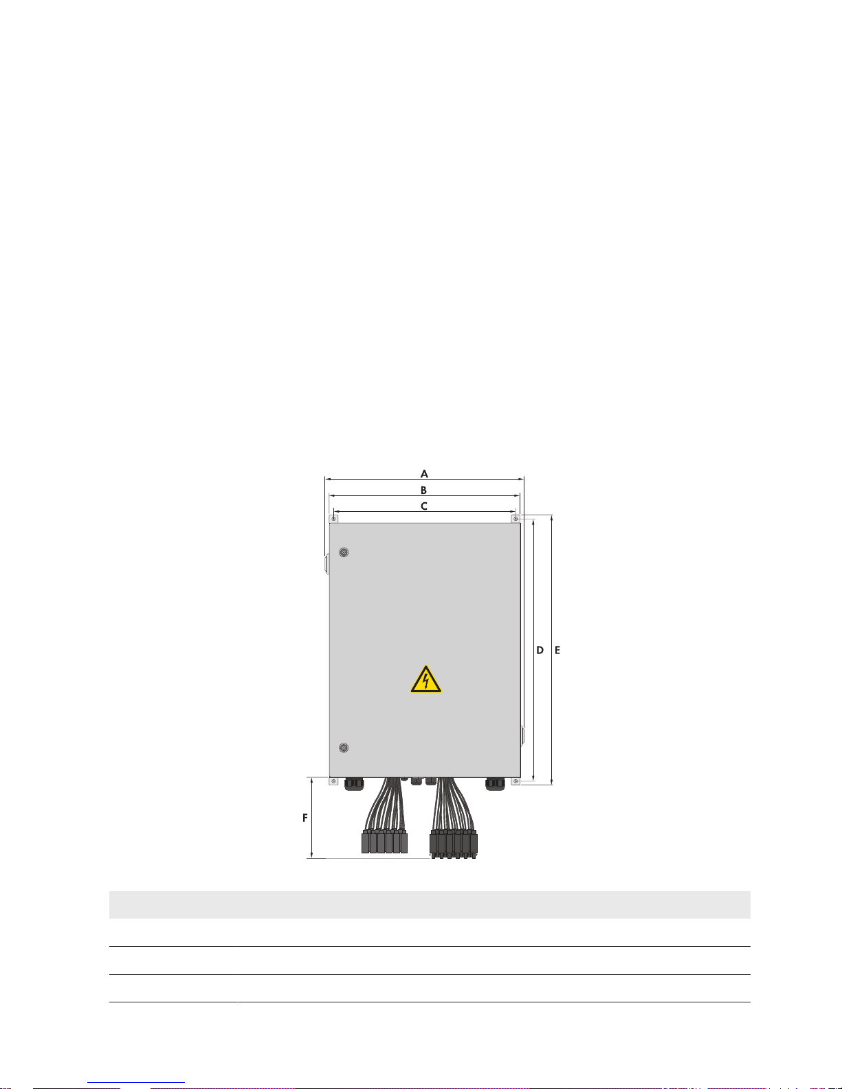
Dimensions:
Figure 7: Dimensions of the SMAString-Monitor
Position Explanation
A 630.00mm
B 600.00mm
C 573.00mm
4 Mounting
SMA Solar Technology AG
Technical Information 9SSMUXX1015-TI-en-10
Page 10
Position Explanation
D 825.60mm
E 850.00mm
F 250.00mm
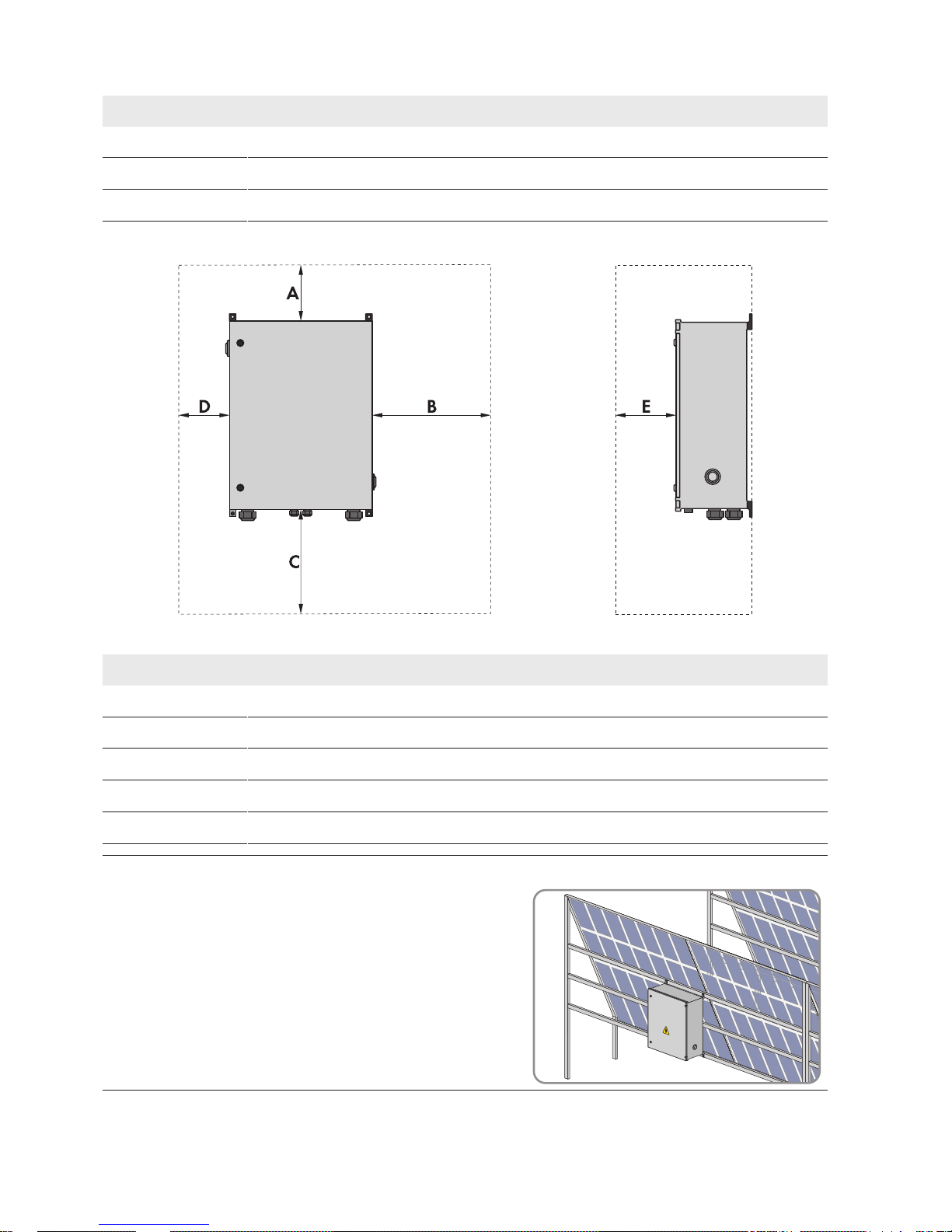
Observe minimum clearances:
Figure 8: Minimum clearances
Position Explanation
A 200mm
B 650mm
C 800mm
D 150mm
E 650mm
Example: mounting on the PV array structure
• If the PV array is mounted on a free-standing structure, the
SMAString‑Monitor can be fixed to this structure in a shaded
position. Make sure that the SMAString-Monitor enclosure is
not mounted in the path of water flowing off the module
surface.
4 Mounting
SMA Solar Technology AG
Technical InformationSSMUXX1015-TI-en-1010
Page 11

Strain Relief for Cables
Strain relief for the cables must be provided for mounting. Strain relief can be effected by means of an external cable
support rail. The cable support rail is not included in the scope of delivery.
4 Mounting
SMA Solar Technology AG
Technical Information 11SSMUXX1015-TI-en-10
Page 12
5 Installation
5.1 Installing the Ethernet Cables
Up to ten SMA String-Monitors can be connected to each string monitoring communication connection of the inverter
in line topology (number of connections for string monitoring communication see the inverter manual).
The Ethernet cables are connected to the LSA+ terminals of the electronics assembly using LSA+ punch down tools.
Interference in data transmission due to unshielded power cables
If unshielded power cables are used, they generate an electromagnetic field during operation which may induce
interference in network cables during data transmission.
• When laying network cables, observe the following minimum clearances to unshielded energy cables:
– For installation without separating strip: at least 200mm
– For installation with aluminum separating strip: at least 100mm
– For installation with steel separating strip: at least 50mm
Requirements for Ethernet cables:
☐ Cable type: copper, two-conductor
☐ Number of insulated conductor pairs and insulated conductor cross-section: 4 x 2 x 0.125mm2 to 0.205mm
2
☐ Cable type: at least Cat5 with shielding S-UTP, F-UTP or higher
☐ Maximum cable length: 100m
☐ The Ethernet cable must be connected in accordance with EIA/TIA 568B (8-conductor):
Signal EIA/TIA 568B (8-conductor)
Insulated conductor color
TX+ White/orange
TX- Orange/white or orange
RX+ White/green
Not assigned Blue/white or blue
Not assigned White/blue
RX- Green/white or green
Not assigned White/brown
Not assigned Brown/white or brown
5.2 Installing the String Cables
The string cables of the PV arrays are connected to the string cables of the SMA String-Monitor via DC connectors. The
string cables of the PV arrays must be equipped with DC connectors for this. The DC connectors are available as an
accessory (see Section8, page24). The DC connectors are pre-installed on the string cables of the SMA StringMonitor.
Damage to the SMA String-Monitor due to moisture penetration
In order to protect the enclosure of the SMA String Monitor from moisture, all unused DC inputs must be closed
with suitable protective caps on the DC connectors. The protective caps are available from Phoenix Contact.
5 Installation
SMA Solar Technology AG
Technical InformationSSMUXX1015-TI-en-1012
Page 13

5.3 Installing the DC Main Cables
You can connect up to two DC main cables per terminal by default.
The material required for the bolted connections is already pre-mounted on the busbar; further material is required
depending on the type of connection and cable. Depending on the cable cross-section, the DC main cables must be
connected to the busbars via terminal lugs or V-box terminals:
The following options are available for connecting the DC main cables:
Connecting DC Main Cables to the Busbar Using Terminal Lugs
• DC main cables 70 mm2 to 400 mm2 made of aluminum or copper
– Aluminum cables: additionally required material: bimetal ring terminal lugs.
– Copper cables: tinned copper ring terminal lugs are pre-mounted.
Connecting DC Main Cables to the Busbar Using V-Box Terminals
• DC main cables 70 mm2 to 300 mm2 made of aluminum or copper
Additionally required material: V-box terminals (see Section8, page24).
Connecting the DC Main Cables with Terminal Lugs
Cable requirements for connection with terminal lugs:
☐ Use copper or aluminum cables only.
☐ The cables must be designed for the maximum PV voltage.
☐ Maximum number of cables per potential: 2
☐ Permitted cable cross-section: 70mm2 to 400 mm
2
Terminal lug requirements:
☐ Use tin-plated terminal lugs only.
☐ For the connection, only the supplied screws, washers and nuts must be used.
☐ The terminal lugs must be designed according to the temperature. Temperature: +95°C
☐ The width of the terminal lugs must exceed the washer diameter. Washer diameter: 32mm. This will ensure that
the defined torques are effective over the whole surface.
☐ Maximum width of the terminal lugs when connecting two cables per potential: 48mm
Connecting the DC Main Cables with V-Box Terminals
The DC main cables are connected directly to the busbars with V-box terminals. The V-box terminals are available as
an accessory.
Cable requirements for connection with V box terminals:
☐ Use copper or aluminum cables only.
☐ The cables must be designed for the maximum PV voltage.
☐ The cables must have double or reinforced insulation.
☐ Maximum number of cables per potential: 2
☐ Permitted cable cross-section: 70mm2 to 300 mm
2
☐ Permitted conductor cross-section:
Cable type Conductor cross-section per potential
Round, single-strand 70mm2to150mm
2
Round, multi-strand 70mm2to300mm
2
5 Installation
SMA Solar Technology AG
Technical Information 13SSMUXX1015-TI-en-10
Page 14

Cable type Conductor cross-section per potential
Sectoral, single-strand 70mm2to240mm
2
Sectoral, multi-strand 70mm2to240mm
2
5 Installation
SMA Solar Technology AG
Technical InformationSSMUXX1015-TI-en-1014
Page 15
6 Network Topology
Network Topology
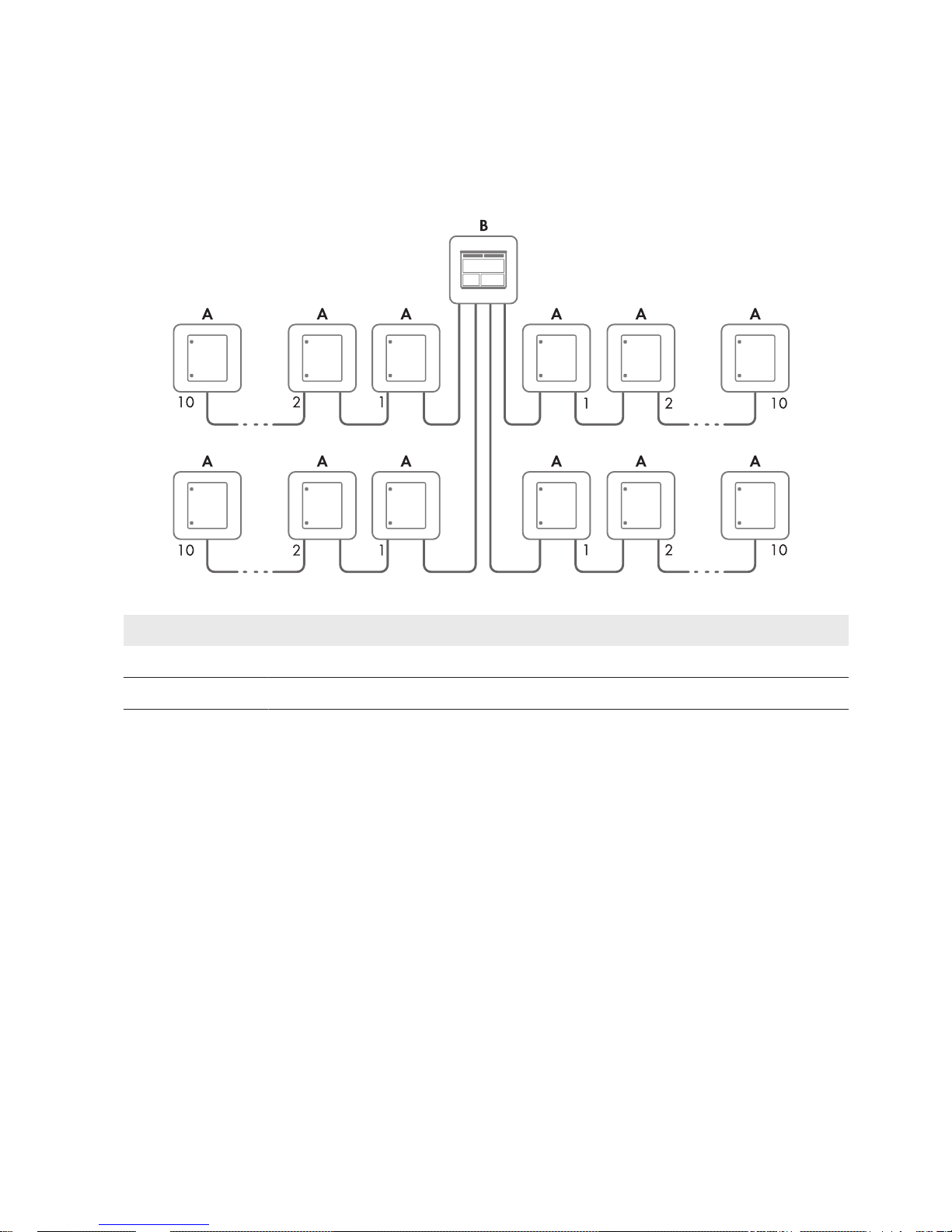
Up to ten SMA String-Monitors can be connected to each string monitoring communication connection of the inverter
in line topology (number of connections for string monitoring communication see the inverter manual).
Figure 9: Network topology with SMA String-Monitor (example)
Position Designation
A SMA String-Monitor
B Inverter (example)
Communication Options
The SMA String-Monitor is equipped by default with Ethernet communication. Distances of up to 100m between two
nodes can be bridged via Ethernet. The SMA String-Monitor can be retrofitted with optical fiber communication, if
required (see Section8, page24). Distances of up to 2,000m between two nodes can be bridged via optical fiber
communication.
Both communication types can be combined between two SMA String-Monitors, meaning that you can use Ethernet
communication and/or optical fiber communication for the communication input and for the communication output
depending on the distance to be bridged.
6 Network Topology
SMA Solar Technology AG
Technical Information 15SSMUXX1015-TI-en-10
Page 16
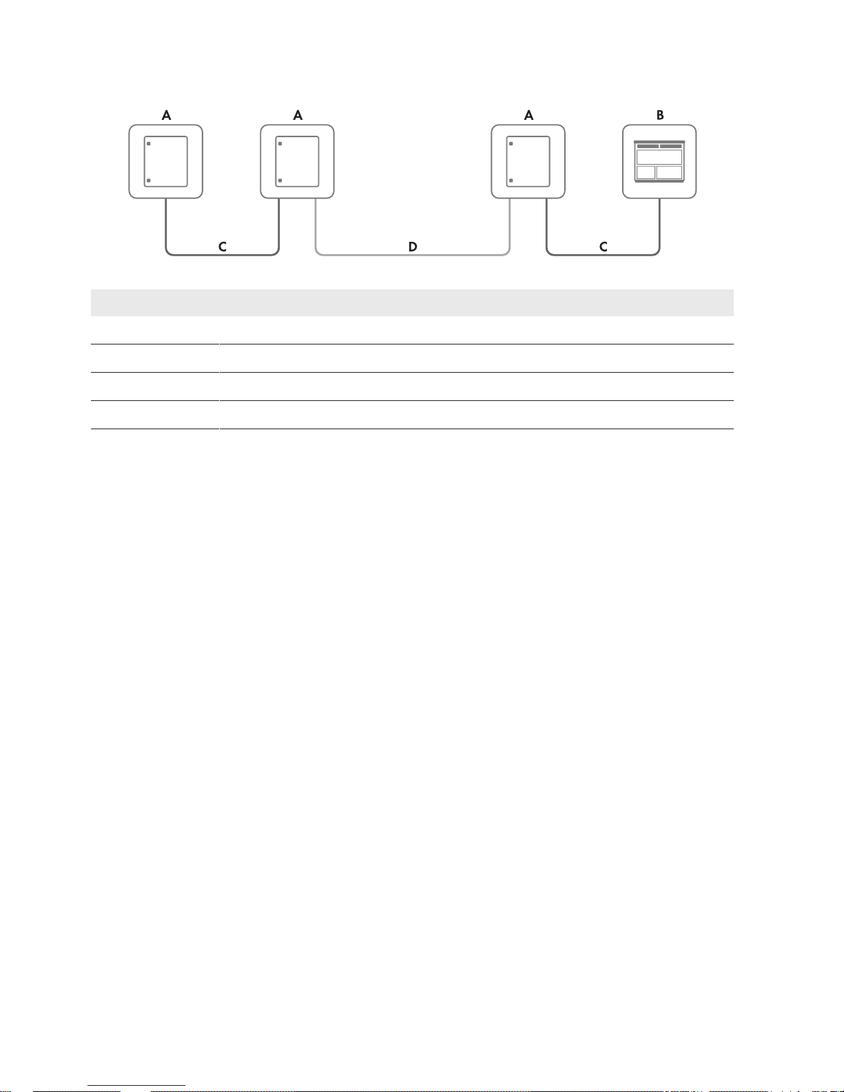
Information on communication options of the inverter can be found in the inverter manual.
Figure 10: Communication options (example)
Position Designation
A SMA String-Monitor
B Inverter (example)
C Ethernet communication
D Optical fiber communication
6 Network Topology
SMA Solar Technology AG
Technical InformationSSMUXX1015-TI-en-1016
Page 17
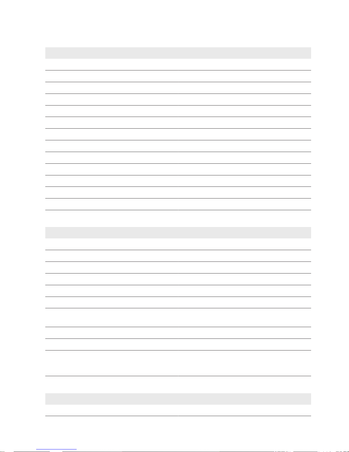
7 Technical Data
Enclosure
Outdoor installation Shaded
Material Glass-fiber reinforced plastic
Combustion properties Self-extinguishing, halogen-free
IP degree of protection in accordance with IEC60529 IP54
IK degree of protection in accordance with IEC62262 IK10
Protection class in accordance with IEC 60529 II
Pollutiondegree in accordance with IEC 61010-1 2
Color RAL7035
UV resistance in accordance with IEC 61439-1 Yes
Wall mounting Yes
Pole mounting* Yes
Lock cylinder Double-bit key for switch cabinet
Cable support rail** Yes
* available as an accessory (see Section8, page24)
** to be provided by the customer
Mechanical Data
Enclosure width 600mm
Enclosure with including vent plug 630mm
Enclosure height including wall bracket lugs 850mm
Enclosure height including string cable harness 1,055mm
Enclosure depth 300mm
Enclosure depth including wall bracket lugs 320mm
Enclosure depth including wall bracket lugs and pole
mounting bracket*
385mm
Maximum weight** 34kg
Weight of pole mounting bracket* 2.1kg
Minimum clearance between enclosure and floor if inline
fuse connectors are installed underneath the SMAStringMonitor
800mm
* available as an accessory (see Section8, page24)
** depending on the number of string inputs of the SMAString-Monitor, without accessories
Electrical Data
PV array Negatively grounded/positively grounded/insulated
7 Technical Data
SMA Solar Technology AG
Technical Information 17SSMUXX1015-TI-en-10
Page 18
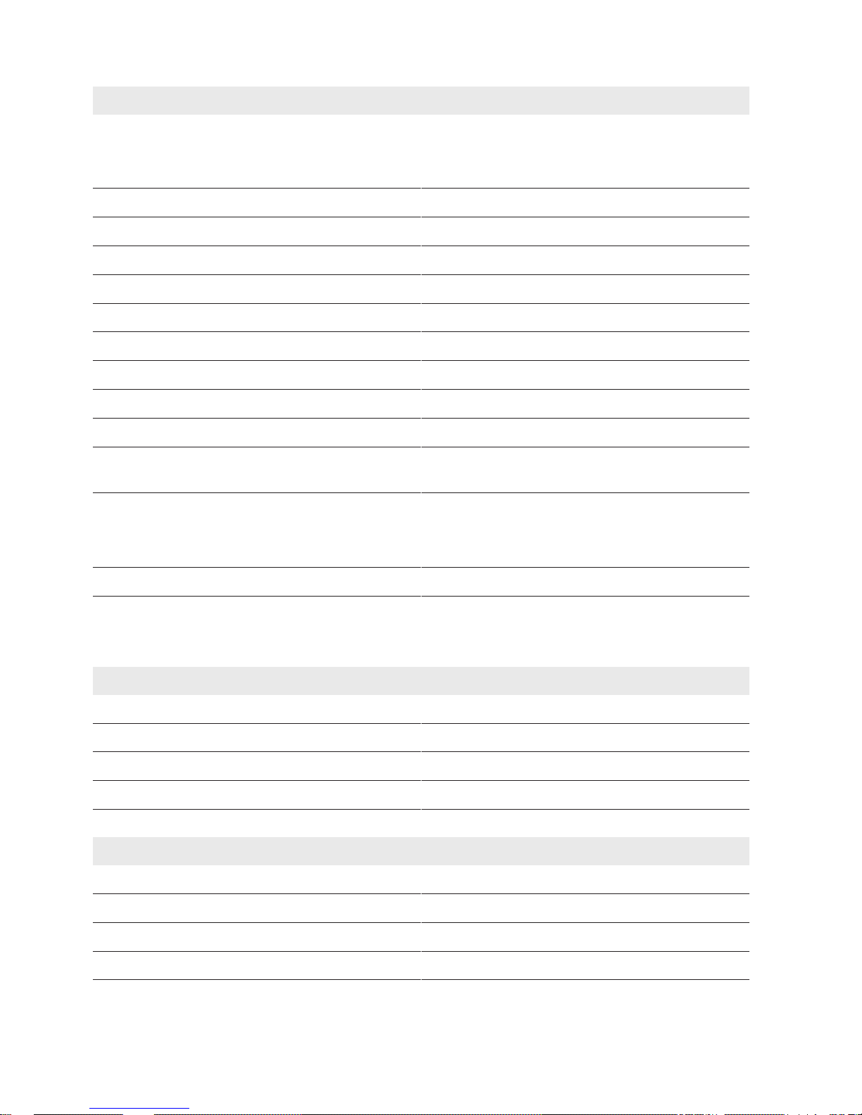
Electrical Data
Rated voltage
At installation altitudes over 2,000m, an additional reduction factor must be taken into account.
1,000VDC / 1,500V
DC
2,001m to 3,000m reduction by 1.0% per 100m
3,001m to 4,000m reduction by 1.2% per 100m
Rated current (I
DCmax
) at 50°C* 315A
DC
Rated current (I
DCmax
) at above 50°C* Reduction by 2.5% per K
Rated current per measuring input* 17.5A
DC
Fuse characteristics gPV
Number of string inputs per potential 16 / 24 / 32
DC supply voltage from PV array +200 VDC to +1,500 V
DC
External AC supply voltage** 230VAC ±20%
DC load-break switch 400 A
DC
DC load-break switch - actuation under load Max. 200 switching cycles
DC load-break switch - actuation
at ‒40°C
Max. 100 switching cycles
Surge arrester DC Type 2 (monitored)
I
nom
= 20kA
I
max
= 40kA
Overvoltage category II
* Maximum continuous operating current up to the specified ambient temperature, taking a maximum irradiation up to 1,200W/m2 into
account (hourly average value of the horizontal global radiation). In case the irradiation is higher, the rated current must be adapted
linearly downwards.
** available as an accessory (see Section8, page24)
Current Measurement
Number of measuring channels 16 / 24 / 32
Current measurement range −2.5 A to +17.5 A
Maximum error at +25°C* ±0.5%
Maximum error in temperature range* ±1.0%
* based on the end value of the current measurement range
Voltage Measurement
Number of measuring channels 1
Voltage measurement range +250 VDC to +1,500 V
DC
Maximum error at +25°C* ±0.5%
Maximum error in temperature range* ±1.0%
* based on the current measurement range end value
7 Technical Data
SMA Solar Technology AG
Technical InformationSSMUXX1015-TI-en-1018
Page 19
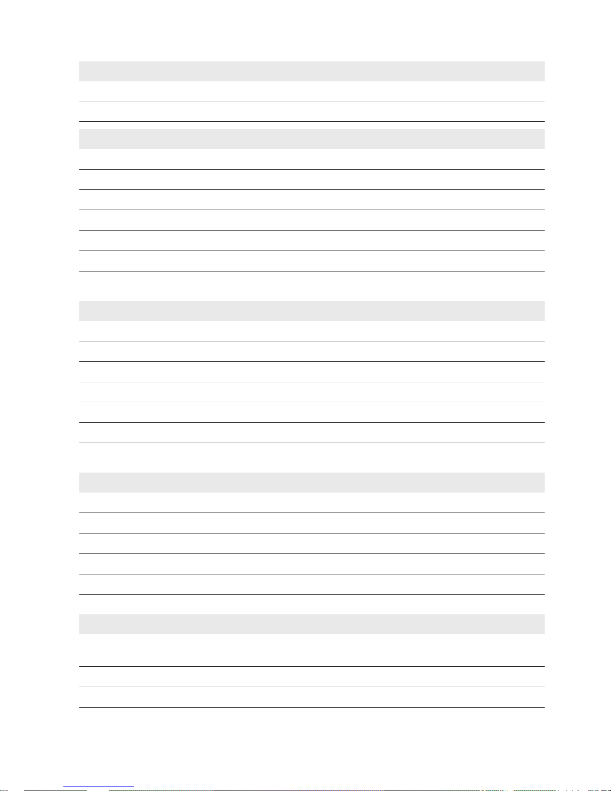
Measurement Internal Temperature SMAString-Monitor
Temperature measurement range −40°C to +100°C
Accuracy ±2% of measuring range end value
DC Main Connection to Busbar
Connection via busbar Ring terminal lugs for M12 screw
Maximum conductor cross-section 400mm
2
Suitable connection material Copper/aluminum*
Number of cables per potential 1 / 2
Cable gland M50
Sealing range of cable glands** 17.0mm to 38.5mm
* with suitable terminal lug (see Section5.3, page13)
** Tightness of seal must be assured using the mounted seal insert or the size-reducing seal insert supplied
DC Main Connection to Box Terminals*
Type of terminal V-Box terminal
Maximum conductor cross-section 300mm
2
Suitable connection material Copper/aluminum
Number of cables per potential 1 / 2
Cable gland M50
Sealing range of cable gland** 17.0mm to 38.5mm
* available as an accessory (see Section8, page24)
** Tightness of seal must be assured using the mounted seal insert or the size-reducing seal insert supplied
Connecting the String Cable to the DC Connector*
Cable type PV 1-F
Conductor cross-section at 6mm2 DC connector 2.5mm2 to6.0mm
2
Cable diameter at 6mm2 DC connector 5mm to 8mm
Conductor cross-section at 16mm2 DC connector 6mm2to16mm
2
Cable diameter at 16mm2 DC connector 5.5mm to 10.0mm
* available as an accessory (see Section8, page24)
Connection Functional Grounding to DC Surge Arrester
Terminal Connecting terminal plate with screw connection for
grounding conductor
Conductor cross-section for surge arrester type 2 25mm2to35mm
2
Cable gland Multiple feed-through
7 Technical Data
SMA Solar Technology AG
Technical Information 19SSMUXX1015-TI-en-10
Page 20
Connection Functional Grounding to DC Surge Arrester
Sealing range of cable gland 5.0mm to 10.2mm
Recommended cable type NYY-O
Connection Functional Grounding to Electronic Assembly
Terminal Spring-cage terminal with actuation lever on the
electronic assembly
Conductor cross-section for surge arrester type 2 6mm
2
Cable gland Multiple feed-through
Sealing range of cable gland 5.0mm to 10.2mm
Recommended cable type NYY-O
Interfaces for Temperature Measurement
Number (module/ambient temperature) 2
Plug-in temperature sensor PT100 and PT1000 with two-, three- and four-wire
measurement
Measurement range −40°C to +100°C
Maximum error at +25°C* ±0.5%
Maximum error in temperature range* ±2.0%
Terminal Spring-cage terminal with actuation lever on the
electronic assembly
Conductor cross-section 0.08mm2to1.00mm
2
Cable gland Multiple feed-through
Sealing range of cable gland 3.2mm to 6.5mm
* based on the measurement range end value (with four-wire measurement)
Digital Input (Customer)
Quantity 1
Supply voltage 24 VDC ±20%
Maximum output current (for sensors) 150mA
Switching threshold, low level V
LMAX
3V
Switching threshold high level V
HMIN
15V
Nominal input voltage 24 V
DC
Nominal input current 5mA
Terminal Spring-cage terminal with actuation lever on the
electronic assembly
7 Technical Data
SMA Solar Technology AG
Technical InformationSSMUXX1015-TI-en-1020
Page 21
Digital Input (Customer)
Conductor cross-section 0.08mm2to1.00mm
2
Maximum cable length 30m
Cable gland Multiple feed-through
Sealing range of cable gland 3.2mm to 6.5mm
Digital Input for Alarm Contact* for DC Load-Break Switch
Quantity 1
Design Potential-free contact
Nominal input voltage (typical) 24 V
DC
Nominal input current (typical) 5mA
Terminal Supplied preassembled cable with plug contact
* available as an accessory (see Section8, page24)
Analog Current Input
Quantity 1
Supply voltage 24 VDC ±20%
Maximum output current (for sensors) 150mA
Input measurement resistance 250Ω
Current measurement range 4 mA to 20 mA
Maximum error at +25°C* ±0.3%
Maximum error in temperature range* ±2.0%
Terminal Spring-cage terminal with actuation lever on the
electronic assembly
Maximum cable length 30m
Conductor cross-section 0.08mm2to1.00mm
2
Cable gland Multiple feed-through
Sealing range of cable gland 3.2mmto6.5mm / 5.0mmto10.2mm
* based on the measuring range end value
Digital Output
Type Potential-free change-over contact
Maximum switching power AC 250VAC / 2A
Maximum switching power DC 24VDC / 2A
48VDC / 1A
7 Technical Data
SMA Solar Technology AG
Technical Information 21SSMUXX1015-TI-en-10
Page 22
Digital Output
Minimum electrical endurance when the maximum switching voltage and maximum switching current are complied
with
1,000,000 switching cycles
Terminal Spring-cage terminal with actuation lever on the
electronic assembly
Conductor cross-section 0.5mm2 to 6.0mm
2
Cable gland Multiple feed-through
Sealing range of cable gland 3.2mmto6.5mm / 5.0mmto10.2mm
Data Transmission Copper Wire
Data interface Modbus (TCP)
Local area network (LAN) Ethernet
Connection without surge arrester LSA+
Connection with surge arrester* RJ45
Recommended cable type Cat5 cable with shielding S-UTP, F-UTP or higher
Maximum cable length 100m
Cable gland Multiple feed-through
Sealing range of cable gland 3.2mmto6.5mm / 5.0mmto10.2mm
* available as an accessory (see Section8, page24)
Data Transmission Optical Fiber*
Data interface Modbus (TCP)
Local area network (LAN) Ethernet
Direct connection multimode optical fiber cable to optical
fiber Piggy-Back**
SC coupling
Fiber type Multimode 50.0/125.0µm or 62.5/125.0µm
Fiber grade OM1 or higher
Connection multimode optical fiber cable to splice box
***
Splicing/optical fiber pigtail SC multimode
Cable gland Multiple feed-through
Sealing range of cable gland 3.2mmto6.5mm / 5.0mmto10.2mm
* Accessory optical fiber Piggy-Back required OF Piggy-Back accessories required (see Section8, page24)
** available as an accessory (see Section8, page24)
*** available as an accessory (see Section8, page24); optical fiber pigtail is not included in the accessory scope of delivery
Ambient Conditions
Standard operating temperature range ‒40°C to +50°C
7 Technical Data
SMA Solar Technology AG
Technical InformationSSMUXX1015-TI-en-1022
Page 23

Ambient Conditions
Extended operating temperature range ‒40°C to +60°C
Storage temperature ‒40°C to +70°C
Relative humidity* 0% to 95%
Maximum altitude above MSL 2,000m / 4,000 m (derating)
* condensation possible
7 Technical Data
SMA Solar Technology AG
Technical Information 23SSMUXX1015-TI-en-10
Page 24
8 Accessories
You will find the accessories for your product in the following overview. If required, these can be ordered from SMA
Solar Technology AG or your distributor.
Designation Brief description SMA order number
Inline fuse connector set Inline fuse connector set consisting of
16 PV inline fuse connectors
See the Technical Information
"IFCON Inline Fuse Connector
Set16"
Y connector set (available soon) Y connector set consisting of 16 Y
connectors
• YCON16SFMM
(female/2male)
• YCON16SMFF (male/2female)
PV connector set PV connector set consisting of 16
connectors for the field wiring
• PVCON16S06F11 (2.5mm2 to
6.0mm2 1,100V (+))
• PVCON16S06M11 (2.5mm
2
to 6.0mm2 1,100V (‒))
• PVCON16S06F15 (2.5mm2 to
6.0mm2 1,500V (+))
• PVCON16S06M15 (2.5mm
2
to 6.0mm2 1,500V (‒))
• PVCON16S16F15 (6.0mm2 to
16.0mm2 1,500V (+))
• PVCON16S16M15 (6.0mm
2
to 16.0mm2 1,500V (‒))
Optical fiber interface module for
SMAString-Monitors
Optical fiber interface module with
multimode SC coupling, type PiggyBack for the SMAString-Monitor
SSM-U-FOPB
Optical fiber splice box set for
SMAString-Monitors
Optical fiber splice box set MM with
two SC/SC Duplex patch cables as
retrofit kit for the SMAString-Monitor
SSM-U-FOSB
SSM-U pole mounting set Set for mounting the SMAString-
Monitor to a pole
SSM-U-PM
Alarm Contact Kit for SMA StringMonitors
Alarm contact set 1NO (make contact) for the switch state indicator for
the SMAString-Monitor
SSM-U-AUXCONT
Ethernet overvoltage protection set
for SMA String-Monitors
Overvoltage protection for the Ethernet communication of the
SMAString-Monitor
SSM-U-COMOVP
Overvoltage protection set for supply
voltage 230 VAC for SMAStringMonitors
Overvoltage protection for external
230VAC supply voltage of the
SMAString-Monitor via the inverter
SSM-U-AUXPBOVP
8 Accessories
SMA Solar Technology AG
Technical InformationSSMUXX1015-TI-en-1024
Page 25

Designation Brief description SMA order number
Power supply assembly for external
power supply of SMAString-Monitors
Assembly for external 230VAC supply voltage of the SMAString-Monitor via the inverter
SSSM-U-AUXPB
V box terminal set for the
SMAString-Monitors SSM-U and
SSMxx-21-BS
V box terminals with connection
brackets
AFC-300
8 Accessories
SMA Solar Technology AG
Technical Information 25SSMUXX1015-TI-en-10
Page 26

SMA Solar Technology
www.SMA-Solar.com
 Loading...