

Page 1

OperatingManual
SMAString-Monitor SSM-U-1615 / SSM-U-2415 / SSMU-3215
SSMUXX15-BE-en-10 | Version 1.0
ENGLISH
Page 2

Legal Provisions
SMA Solar Technology AG
Legal Provisions
The information contained in these documents is property of SMA Solar Technology AG. Any
publication, whether in whole or in part, requires prior written approval by SMA Solar Technology
AG. Internal reproduction used solely for the purpose of product evaluation or other proper use is
allowed and does not require prior approval.
SMA Warranty
You can download the current warranty conditions from the Internet at www.SMA-Solar.com.
Trademarks
All trademarks are recognized, even if not explicitly identified as such. A lack of identification does
not mean that a product or symbol is not trademarked.
The BLUETOOTH® word mark and logos are registered trademarks of BluetoothSIG,Inc. and any
use of these marks by SMASolarTechnologyAG is under license.
Modbus® is a registered trademark of Schneider Electric and is licensed by the Modbus
Organization, Inc.
QR Code is a registered trademark of DENSO WAVE INCORPORATED.
Phillips® and Pozidriv® are registered trademarks of Phillips Screw Company.
Torx® is a registered trademark of Acument Global Technologies, Inc.
SMASolarTechnologyAG
Sonnenallee 1
34266 Niestetal
Germany
Tel. +49 561 9522-0
Fax +49 561 9522-100
www.SMA.de
E-mail: info@SMA.de
© 2004 to 2015SMASolarTechnologyAG. All rights reserved.
Operating ManualSSMUXX15-BE-en-102
Page 3

SMA Solar Technology AG
Table of Contents
Table of Contents
1 Information on this Document ................................................. 6
1.1 Validity................................................................................................ 6
1.2 Target Group...................................................................................... 6
1.3 Additional Information....................................................................... 6
1.4 Symbols .............................................................................................. 6
1.5 Typographies...................................................................................... 7
1.6 Nomenclature..................................................................................... 7
2 Safety......................................................................................... 8
2.1 Intended Use ...................................................................................... 8
2.2 Safety Information.............................................................................. 9
2.3 Personal Protective Equipment........................................................... 11
3 Scope of Delivery...................................................................... 12
4 Product Overview..................................................................... 13
4.1 SMA String-Monitor........................................................................... 13
4.2 External View of the DC Subdistribution........................................... 14
4.3 Components of the DC Subdistribution ............................................ 15
4.4 Terminals on the Electronic Assembly............................................... 17
4.5 Type Label .......................................................................................... 18
4.6 Symbols on the Product ..................................................................... 19
4.7 LEDs on the Electronic Assembly....................................................... 20
5 Mounting ................................................................................... 21
5.1 Selecting the Mounting Location....................................................... 21
5.2 Mounting the SMA String-Monitor on the Wall............................... 23
6 Installation................................................................................. 25
6.1 Overview of the Connection Area of the SMA String-Monitor....... 25
6.2 Grounding ......................................................................................... 27
6.2.1 Information on Grounding............................................................. 27
6.2.2 Grounding the Electronic Assembly.............................................. 27
6.2.3 Grounding the DC Surge Arrester ................................................ 27
6.3 Installation of the DC Main Cables .................................................. 28
Operating Manual 3SSMUXX15-BE-en-10
Page 4

Table of Contents
6.3.1 Safety during Installation of the DC Main Cables....................... 28
6.3.2 Options for Installation of the DC Main Cables .......................... 28
6.3.3 Connecting the DC Main Cables to the Busbar using Terminal
Lugs................................................................................................. 29
6.3.4 Connecting the DC Main Cables to the Busbar using V Box
Terminals......................................................................................... 32
6.3.4.1 Requirements and Conditions................................................. 32
6.3.4.2 Installing the Box Terminal on the Busbar.............................. 33
6.3.4.3 Connecting Copper Cables to V-Box Terminal...................... 34
6.3.4.4 Connecting Aluminum Cables to V Box Terminal.................. 35
SMA Solar Technology AG
6.4 Connecting the Ethernet Cables........................................................ 36
6.5 Connection of Sensors....................................................................... 39
6.5.1 Connecting Temperature Sensors ................................................. 39
6.5.2 Connecting an Irradiation Sensor or Anemometer to the
Analog Input................................................................................... 39
6.6 Connecting the Remote Terminal to the Digital Input....................... 40
6.7 Connecting the Remote Terminal to the Digital Output ................... 41
6.8 Installation of the String Cables ........................................................ 42
6.8.1 Requirements for Installation of the String Cables ....................... 42
6.8.2 Installing the String Cables............................................................ 42
7 Commissioning the DC Subdistribution................................... 45
8 Disconnecting and Reconnecting............................................. 46
8.1 Safety When Disconnecting and Reconnecting Voltage Sources .. 46
8.2 Disconnecting the DC Subdistribution............................................... 47
8.3 Switching the DC Subdistribution Back On...................................... 47
9 Troubleshooting ........................................................................ 49
9.1 LED States........................................................................................... 49
9.1.1 Status LEDs of the SMA String-Monitor ........................................ 49
9.1.2 LEDs of the Network Connection.................................................. 50
9.2 Performing an Update ....................................................................... 51
10 Maintenance ............................................................................. 52
10.1 Safety during Maintenance............................................................... 52
10.2 Maintenance Schedule and Consumables ...................................... 53
Operating ManualSSMUXX15-BE-en-104
Page 5

SMA Solar Technology AG
10.2.1 Notes on Maintenance Work....................................................... 53
10.2.2 Maintenance Work Every 24 Months.......................................... 53
Table of Contents
10.3 Maintenance Work............................................................................ 54
10.3.1 Checking the DC Load-Break Switch............................................ 54
10.3.2 Checking the Protective Covers..................................................... 55
10.3.3 Performing the Visual Inspection ................................................... 55
10.3.4 Checking the Condensate Drain................................................... 56
10.3.5 Checking the Vent Plug.................................................................. 56
10.3.6 Checking the Seals ........................................................................ 56
10.3.7 Checking the Labels....................................................................... 57
10.3.8 Checking the LEDs.......................................................................... 58
10.3.9 Checking the Bolted, Clamp and Plug Connections.................... 58
10.3.10 Checking the Inline Fuse Connectors............................................ 59
10.3.11 Checking the Ground Connection ................................................ 59
10.4 Completing Maintenance Work ....................................................... 59
11 Decommissioning ...................................................................... 60
11.1 Decommissioning the DC Subdistribution......................................... 60
11.2 Disassembling the DC Subdistribution from the Wall...................... 60
11.3 Packing the DC Subdistribution......................................................... 61
11.4 Storing the DC Subdistribution.......................................................... 61
11.5 Disposing of the DC Subdistribution................................................. 61
12 Periodic Actions......................................................................... 62
12.1 Inserting the Cables ........................................................................... 62
12.1.1 Leading Cables through Enclosure Opening with Membrane.... 62
12.1.2 Leading Cables through Enclosure Opening with Cable Gland 62
12.2 Disassembling and Mounting the Protective Covers........................ 63
13 Technical Data........................................................................... 65
14 Accessories ................................................................................ 72
15 Contact....................................................................................... 74
Operating Manual 5SSMUXX15-BE-en-10
Page 6
1 Information on this Document
SMA Solar Technology AG
1 Information on this Document
1.1 Validity
This document is valid for the SMAString-Monitor of the following device types from production
version A1:
• SSM-U-1615
• SSM-U-2415
• SSM-U-3215
1.2 Target Group
The tasks described in this document must only be performed by qualified persons. Qualified
persons must have the following skills:
• Knowledge of how the product works and is operated
• Training in how to deal with the dangers and risks associated with installing and using
electrical devices and systems
• Training in the installation and commissioning of electrical devices and systems
• Knowledge of all applicable standards and directives
• Knowledge of and adherence to this manual and all safety precautions
1.3 Additional Information
Links to additional information can be found at www.SMA-Solar.com.
1.4 Symbols
Symbol Explanation
Indicates a hazardous situation which, if not
avoided, will result in death or serious injury
Indicates a hazardous situation which, if not
avoided, can result in death or serious injury
Indicates a hazardous situation which, if not
avoided, can result in minor or moderate injury
Indicates a situation which, if not avoided, can
result in property damage
Information that is important for a specific topic
or goal, but is not safety-relevant
Indicates a requirement for meeting a specific
goal
Desired result
A problem that might occur
Operating ManualSSMUXX15-BE-en-106
Page 7

SMA Solar Technology AG
1 Information on this Document
1.5 Typographies
Typographies Use Example
bold
>
[Button/Key]
• Display messages
• Elements on a user
interface
• Terminals
• Slots
• Elements to be selected
• Elements to be entered
• Connects several elements
to be selected
• Button or key to be
selected or pressed
• Set parameter WGra to
0.2.
• Select PV system >
Detect.
• Select [Start detection].
1.6 Nomenclature
In this document, the SMAString‑Monitor is also referred to as "DC subdistribution" or "product".
Operating Manual 7SSMUXX15-BE-en-10
Page 8

2 Safety
SMA Solar Technology AG
2 Safety
2.1 Intended Use
The SMAString‑Monitor is a PV array junction box to which several strings can be connected in
parallel. The SMAString-Monitor monitors the input currents of the strings and detects failures, thus
helping to minimize power and yield losses.
The SMAString‑Monitor can be operated in large-scale PV power plants with central inverters from
SMA Solar Technology AG or other PV inverters.
The maximum current values for the SMAString-Monitor must not be exceeded.
The SMAString-Monitor should only be operated when the strings are fuse protected. SMA Solar
Technology AG guarantees safe operation of the SMAString-Monitor with inline fuse connectors as
string fuses, providing that the inline fuse connectors are connected directly to the DC connectors of
the string cables on the DC subdistribution. For any other type or location of the string fusing, SMA
Solar Technology AG cannot guarantee safe operation of the SMAString-Monitor or compliance
with the required thresholds. The inline fuse connectors are available as accessories.
The product is suitable for indoor and outdoor use.
All work on the product must only be performed using appropriate tools and in compliance with the
ESD protection regulations.
The installation of SMA accessories in the product is permissible without specific approval by SMA
Solar Technology AG, providing that the product supports the given SMA accessories (see
Section14, page72).
The product must only be used in countries for which it is approved or released by SMA Solar
Technology AG and the grid operator.
Use this product only in accordance with the information provided in the enclosed documentation
and with the locally applicable standards and directives. Any other application may cause
personal injury or property damage.
Alterations to the product, e.g. changes or modifications, are only permitted with the express written
permission of SMA Solar Technology AG. Unauthorized alterations will void guarantee and
warranty claims and usually void the operating license. SMA Solar Technology AG shall not be
held liable for any damage caused by such changes.
Any use of the product other than that described in the Intended Use section does not qualify as
appropriate.
The enclosed documentation is an integral part of this product. Keep the documentation in a
convenient place for future reference and observe all instructions contained therein.
The type label must remain permanently attached to the product.
Operating ManualSSMUXX15-BE-en-108
Page 9
SMA Solar Technology AG
2 Safety
2.2 Safety Information
This section contains safety information that must be observed at all times when working on or with
the product. To prevent personal injury and property damage and to ensure long-term operation of
the product, read this section carefully and observe all safety information at all times.
Danger to life from electric shock due to live voltage
High voltages are present in the live components of the product. Touching live components results
in death or serious injury due to electric shock.
• Wear suitable personal protective equipment for all work on the product.
• Do not touch any live components.
• Unless live voltage is absolutely necessary, always disconnect the product from voltage
sources before performing any work (see Section8 "Disconnecting and Reconnecting",
page46).
Danger to life from electric shock due to live DC cables
DC cables connected to PV modules that are exposed to sunlight are energized. Touching live
cables results in death or serious injury due to electric shock.
• Prior to assembling the DC cables, ensure that the DC cables are voltage-free.
• Wear suitable personal protective equipment for all work on the product.
Danger to life from electric shock due to ground fault
If there is a ground fault, system components that are supposedly grounded may in fact be live.
Touching incorrectly grounded components results in death or serious injuries from electric shock.
• Before working on the system, ensure that no ground fault is present.
• Wear suitable personal protective equipment for all work on the product.
Danger to life from electric shock due to damaged product
Operating a damaged product can lead to hazardous situations that result in death or serious
injuries due to electric shock.
• Only operate the product when it is in a flawless technical condition and safe to operate.
• Check the product regularly for visible damage.
• Make sure that all external safety equipment is freely accessible at all times.
• Make sure that all safety equipment is in good working order.
• Wear suitable personal protective equipment for all work on the product.
Operating Manual 9SSMUXX15-BE-en-10
Page 10
2 Safety
SMA Solar Technology AG
Danger to life from electric shock if the product is not locked
If the product is not locked, unauthorized persons will have access to live components carrying
lethal voltages. Touching live components can result in death or serious injury due to electric
shock.
• Always close and lock the product.
• Remove the keys.
• Store the keys in a safe place.
• Ensure that no unauthorized persons have access to the closed electrical operating area.
Danger to life from electric shock if the DC load-break switch is damaged
Switching the DC load-break switch at temperatures belowthe specified threshold may damage
the DC load-break switch. The threshold is: ‒25°C. In this case, reliable disconnection can no
longer be guaranteed.
If the DC load-break switch is switched in spite of visible damage, again the reliable
disconnection function cannot be guaranteed.
High voltages are present in components that are not properly disconnected. Touching live
components can result in death or serious injury due to electric shock.
• Do not switch the DC load-break switch at temperatures below the specified threshold. The
threshold is: ‒25°C.
• Do not switch the DC load-break switch if it is visibly damaged.
Risk of burns due to hot components
Some components of the product can get very hot during operation. Touching these components
can cause burns.
• Observe the warnings on all components.
• During operation, do not touch any components marked with such warnings.
• Wear suitable personal protective equipment for all work on the product.
Damage to the PV system due to incorrectly rated fuses
If fuses are incorrectly rated, excessive reverse currents can destroy the PV modules.
• Observe the maximum current values for the product when rating the fuses.
Operating ManualSSMUXX15-BE-en-1010
Page 11
SMA Solar Technology AG
Property damage due to dust intrusion and moisture penetration
Dust or moisture intrusion can damage the product and impair its functionality.
• Do not open the enclosure during rainfall or when humidity exceeds the specified threshold.
The threshold for humidity is: 95 %.
• Only perform maintenance work when the environment is dry and free of dust.
• Operation of the product is only permitted when it is closed.
• If the installation or commissioning process is interrupted, mount all panels.
• Close and lock the enclosure.
• The product must always be closed for storage.
• Store the product in a dry and covered location.
• Temperature at the storage location must be in the specified range. The temperature range
is: ‒40°Cto+70°C.
Damage to electronic components due to electrostatic discharge
Electrostatic discharge can damage or destroy electronic components.
• Observe the ESD safety regulations when working on the product.
• Wear suitable personal protective equipment for all work on the product.
• Discharge electrostatic charge by touching grounded elements. Only then is it safe to touch
electronic components.
2 Safety
2.3 Personal Protective Equipment
Always wear suitable protective equipment
When working on the product, always wear the appropriate personal protective equipment
for the specific job.
The following personal protective equipment is regarded to be the minimum requirement:
☐ In a dry environment, safety shoes of categoryS3 with perforation-proof soles and steel toe
caps
☐ During precipitation or on moist ground, safety boots of categoryS5 with perforation-proof
soles and steel toe caps
☐ Tight-fitting work clothes made of 100%cotton
☐ Suitable work pants
☐ Individually fitted hearing protection
☐ Safety gloves
Any other prescribed protective equipment must also be used.
Operating Manual 11SSMUXX15-BE-en-10
Page 12

3 Scope of Delivery
SMA Solar Technology AG
3 Scope of Delivery
Check the scope of delivery for completeness and any externally visible damage. Contact your
distributor if the scope of delivery is incomplete or damaged.
Figure 1: Components included in the scope of delivery
Position Quantity Designation
A 1 SMAString-Monitor
B 1 Switch cabinet key
C 4 Size-reducing seal inserts
D 1 Operating manual and circuit diagram
Operating ManualSSMUXX15-BE-en-1012
Page 13
SMA Solar Technology AG
4 Product Overview
4 Product Overview
4.1 SMAString-Monitor
The SMAString‑Monitor is a PV array junction box to which several strings can be connected in
parallel. The SMAString‑Monitor can be operated in large-scale PV power plants with central
inverters from SMA Solar Technology AG or other PV inverters.
The essential tasks performed by the SMAString-Monitor are:
• to bundle the input currents of the strings
• to measure the input currents of the strings and transfer these to the inverter
• to transmit information on the input currents of the strings
This enables failures to be recognized and power and yield losses to be minimized.
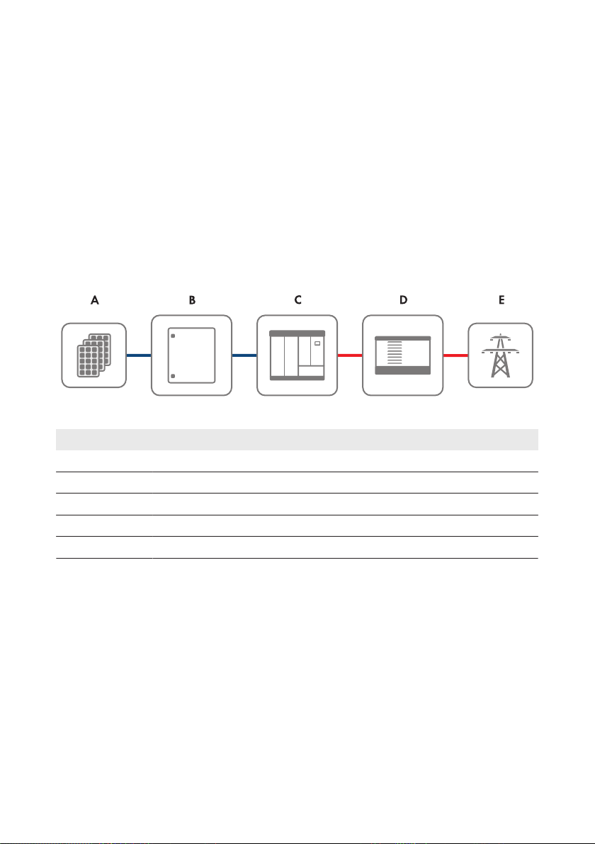
Principle of a grid-tie PV system with SMAString-Monitor
Figure 2: Principle of a grid-tie PV system with SMAString-Monitor
Position Designation
A PV array
B SMAString-Monitor
C Sunny Central
D Transformer
E Utility grid
Operating Manual 13SSMUXX15-BE-en-10
Page 14
4 Product Overview
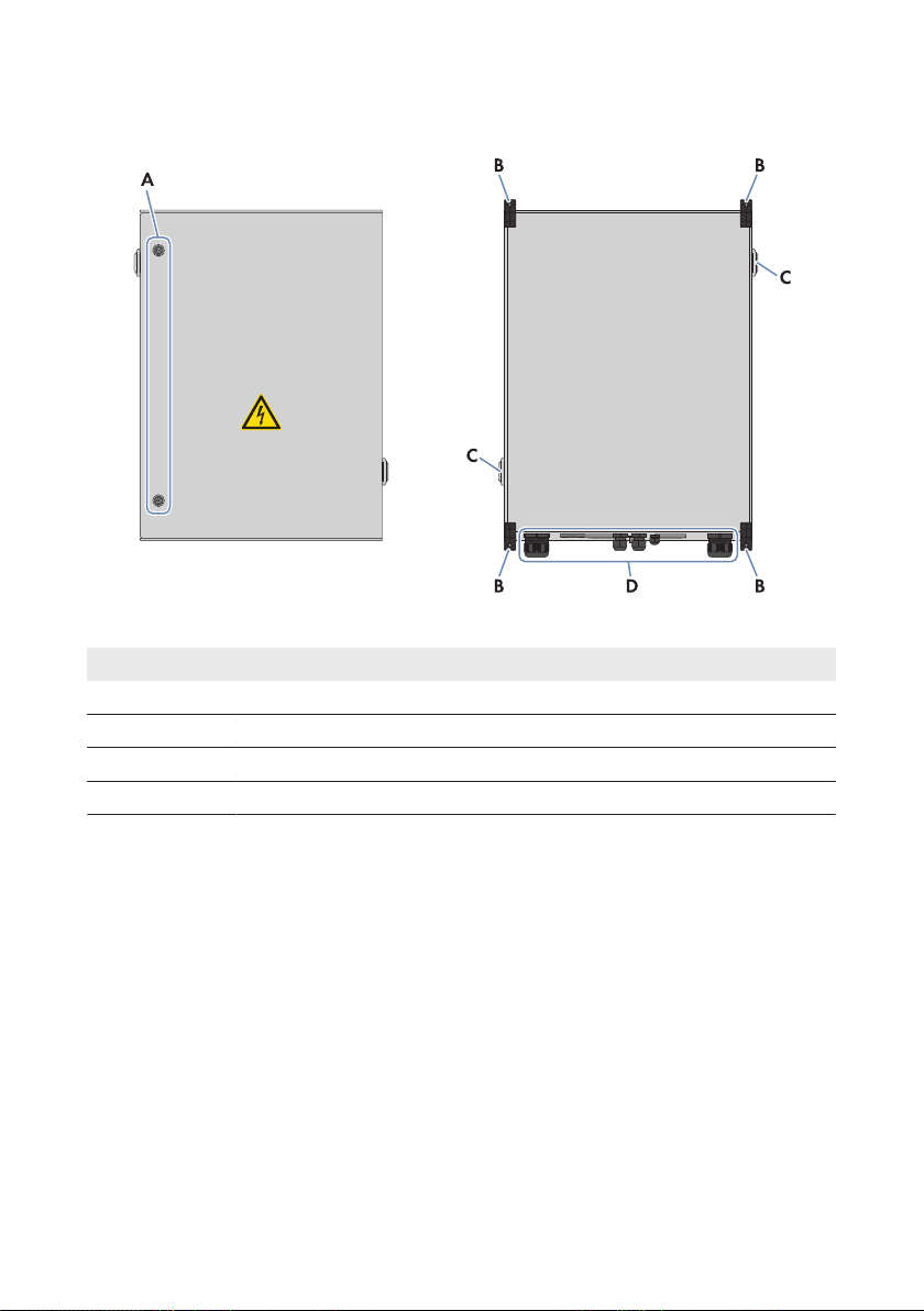
4.2 External View of the DC Subdistribution
Figure 3: External view of the DC subdistribution
Position Designation
A Lock cylinder
B Wall bracket lugs
C Vent plug
D Enclosure openings for introducing the cables
SMA Solar Technology AG
Operating ManualSSMUXX15-BE-en-1014
Page 15

SMA Solar Technology AG
4.3 Components of the DC Subdistribution
4 Product Overview
Figure 4: Components of the DC subdistribution
Position Designation
A DC overvoltage protection
B DC Load-Break Switch
C Terminal for connection of the DC overvoltage protection unit to the functional
grounding
Operating Manual 15SSMUXX15-BE-en-10
Page 16

4 Product Overview
Position Designation
D Rotary handle of the DC load-break switch
E Electronic assembly
Protective covers
SMA Solar Technology AG
Figure 5: Position of the protective covers
Position Designation
A Top protective cover
B Bottom protective cover
Operating ManualSSMUXX15-BE-en-1016
Page 17

1 2 3 4 5 6 7 8 9 1112 14
A
B
C
D
E
F
G
H
K
L
M
N
OP
Q
I
SMA Solar Technology AG
4 Product Overview
4.4 Terminals on the Electronic Assembly
Figure 6: Terminals on the electronic assembly
Position Designation Explanation
A ‒ Connection of string cable harnesses (PV+) and, depend-
ing on the version, of the plug-in board (MEU) for the num-
ber of PV inputs (factory installed)
B X1 Analog current input
C X2 Analog input temperature sensor external 1 (EXT 1)
D X3 Analog input temperature sensor external 2 (EXT 2)
E X4 Digital customer input
F X5 Digital input surge arrester DC
G X6 Status alarm contact DC load-break switch
H X7 Ethernet communication output LAN OUT
I X8 Terminal for the functional grounding cable of the elec-
tronic assembly
K X9 Ethernet communication input LAN IN
L LWLPB 1 Slot for the OF interface module (communication input
LWL IN)
M LWLPB 2 Slot for the OF interface module (communication output
LWL OUT)
N ‒ Digital output of potential-free change-over contact
Operating Manual 17SSMUXX15-BE-en-10
Page 18

4 Product Overview
Position Designation Explanation
O ‒ Slot for the power supply assembly for external 230V
supply voltage to the SMAString-Monitor via the inverter
P ‒ Terminal for supply voltage of the SMAString-Monitor
from the PV field (PV-) (factory installed)
Q ‒ Fuse for the supply voltage of the SMAString-Monitor
from the PV field
SMA Solar Technology AG
AC
4.5 Type Label
The type label clearly identifies the product.
You will require the information on the type label to use the product safely and when seeking
customer support from Service (see Section15, page74). The type label must remain permanently
attached to the product.
SMAString-Monitor
There are two type labels attached to the SMAString‑Monitor. The type labels are located on the
inside of the right-hand door and on the right-hand outside panel of the SMAString‑Monitor.
You can read off the following data from the type label:
• Date of manufacture (Fabrication Date)
• Serial number (SER)
• Device type (SSM-U-XXXX XX/XX/XX)
• Device-specific characteristics
Electronic assembly
There is one type label attached to the electronic assembly. The type label is located at the top left
of the electronic assembly.
You can read off the following data from the type label:
• Production version (FA)
• Serial number (SER)
• Assembly type and version (SSM30BASE.XXX)
Plug-in board (MEU) for the number of PV inputs
There is one type label attached to the plug-in board.
You can read off the following data from the type label:
• Production version (FA)
• Serial number (SER)
• Assembly type and version (SSM30MEU.XXX)
Operating ManualSSMUXX15-BE-en-1018
Page 19

SMA Solar Technology AG
4 Product Overview
4.6 Symbols on the Product
The following gives an explanation of all the symbols found on the SMAString-Monitor and on the
type label.
Symbol Designation Explanation
CE marking The product complies with the requirements of the applica-
ble EU directives.
DataMatrix code 2Dcode for device-specific characteristics
Degree of protectionIP54
Protection class II The product has a reinforced or double insulation be-
WEE marking Do not dispose of the product together with household
Beware of dangerous
voltage
Beware of hot surface The product can get hot during operation. Avoid contact
Observe the documentation
The product is protected against interior dust deposits and
splashing water from all angles.
tween grid current circuit and output voltage.
waste but in accordance with the locally applicable dis-
posal regulations for electronic waste.
The product operates at high voltages. All work on the
product must be carried out by qualified persons only.
during operation. Allow the product to cool down suffi-
ciently before carrying out any work. Wear personal pro-
tective equipment such as safety gloves.
Observe all documentation supplied with the product.
Operating Manual 19SSMUXX15-BE-en-10
Page 20

L‒L+
LK/ACT
SPEED
LK/ACT
SPEED
UPD
ERR
AL
PWR
COM
A
B
C
D
E
4 Product Overview
SMA Solar Technology AG
4.7 LEDs on the Electronic Assembly
Figure 7: LEDs on the electronic assembly
Position Designation Color Explanation
A UPD yellow Update status of the SMAString-Moni-
tor
ERR red Error in the SMAString-Monitor
AL green Firmware status of the SMAString-
Monitor
PWR green Voltage supply status of the
SMAString-Monitor
COM yellow Communication status of the
SMAString-Monitor
B LK/ACT green Status/activity of the network connec-
tion at the communication output
C SPEED yellow Speed of the network connection at
the communication output
D LK/ACT green Status/activity of the network connec-
tion at the communication input
E SPEED yellow Speed of the network connection at
the communication input
A description of the LED states will by given in (see Section9.1, page49).
Operating ManualSSMUXX15-BE-en-1020
Page 21
SMA Solar Technology AG
5 Mounting
5 Mounting
5.1 Selecting the Mounting Location
Fire hazard due to wrong choice of mounting location
Despite careful construction, electrical devices can cause fires.
• Do not mount the DC sub-distribution on flammable construction materials.
• Do not mount the DC sub-distribution in areas containing highly flammable materials.
• Do not mount the DC sub-distribution in potentially explosive atmospheres.
Requirements for the mounting location:
☐ The mounting location can be outdoors or indoors.
☐ The mounting location must not be in a living or office area.
☐ The mounting location must not block any escape routes.
☐ The mounting location must be freely and safely accessible at all times without the necessity for
any auxiliary equipment (e.g. scaffolding or lifting platforms). Non-fulfillment of these criteria
may restrict servicing.
☐ The mounting location must be shaded, e.g. under a protective roof.
☐ The mounting location must be suitable for the weight and dimensions of the SMA
SunnyString‑Monitor.
☐ The mounting location must be suitable for the wind load.
☐ Mounting space below the SMAStringMonitor when using the inline fuse connectors:
at least 800mm.
Requirements for mounting the SMAString-Monitor
☐ Mount the SMASunnyString-Monitor so that the connection area is facing downwards.
☐ Mount the SMAString-Monitor in a horizontal position.
☐ Do not mount the SMAString Monitor in a twisted manner.
☐ Do not mount the SMASunnyString‑Monitor in a horizontal or inclined position.
☐ An external cable support rail must be provided.
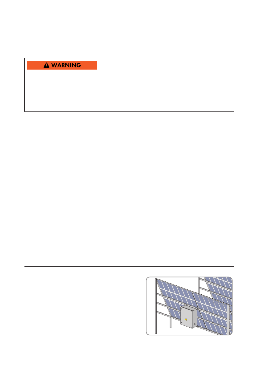
Example: Mounting on PV array substructure
• If the PV array is mounted on a free-standing
structure, the DC subdistribution can be fixed to
this structure in a shaded position. In this case,
make sure that there is no danger of rainwater
flowing off the module surface and over the
enclosure of the DC subdistribution.
Operating Manual 21SSMUXX15-BE-en-10
Page 22

5 Mounting
Dimensions and anchoring points:
Figure 8: Dimensions and anchoring points
Position Explanation
A 630.00mm
B 600.00mm
C 573.00mm (space between anchoring points)
D 825.60mm (space between anchoring points)
E 850.00mm
F 250.00mm
SMA Solar Technology AG
Operating ManualSSMUXX15-BE-en-1022
Page 23
SMA Solar Technology AG
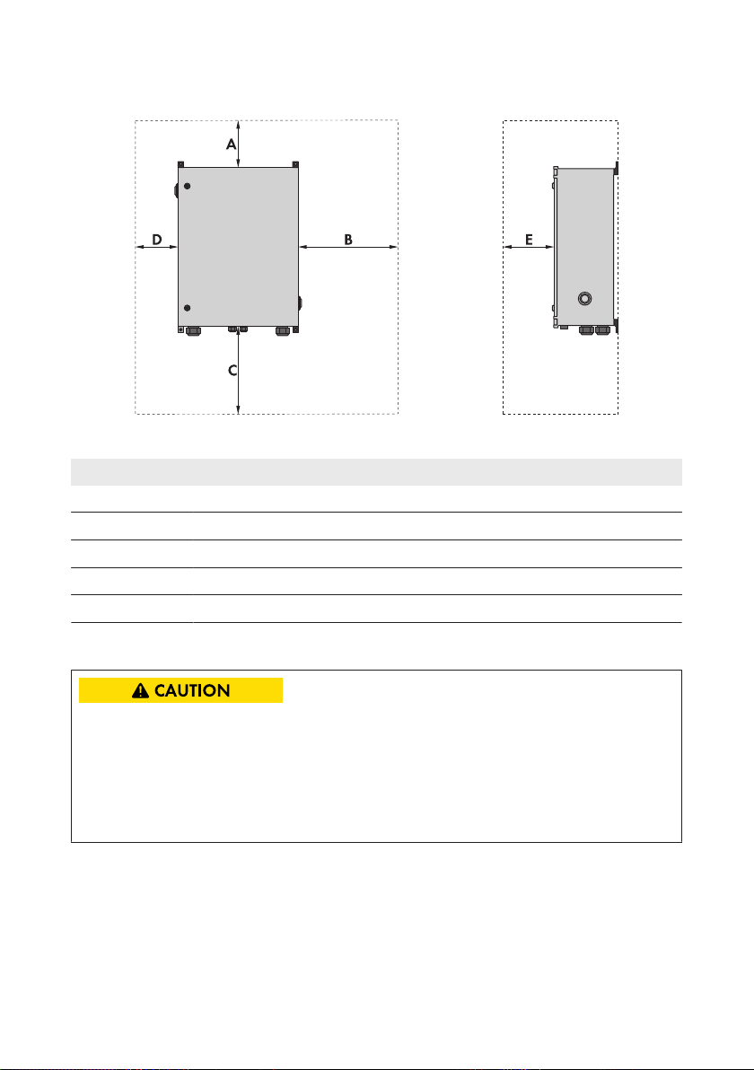
Observe minimum clearances:
Figure 9: Minimum clearances
Position Explanation
A 200mm
B 650mm
C 800mm
D 150mm
E 650mm
5 Mounting
5.2 Mounting the SMAString-Monitor on the Wall
Risk of injury when lifting the DC sub-distribution, or if it is dropped
There is risk of injury if the DC sub-distribution is lifted incorrectly or dropped while being
transported or when attaching it to or removing it from the wall mounting bracket. Weight of the
DC sub-distribution without installed accessories: 35 kg.
• Two persons are required for mounting and disassembling the DC sub-distribution.
• Carefully lift and transport the DC sub-distribution.
Additionally required mounting material (not included in the scope of delivery):
• For mounting the DC subdistribution on a wall:
– 4 screws M6. Take the wall properties into account when selecting the screws.
– 4 washers
Operating Manual 23SSMUXX15-BE-en-10
Page 24

5 Mounting
SMA Solar Technology AG
– 4 screw anchors if necessary. Take the wall properties into account when selecting the
screw anchors.
• For mounting the DC subdistribution on the PV module substructure:
– 4 screws M6
– 4 washers
– 4 nuts
Procedure:
1. Close the DC subdistribution.
2. Mark the position of the drill holes on the wall or support structure.
3. Drill holes at the marked positions.
4. If necessary, insert screw anchors.
5. Fasten the DC subdistribution to the wall or
substructure using suitable screws and washers.
6. Ensure that the DC subdistribution is securely attached.
Operating ManualSSMUXX15-BE-en-1024
Page 25

SMA Solar Technology AG
6 Installation
6 Installation
6.1 Overview of the Connection Area of the SMA StringMonitor
View from Below
Figure 10: View of the SMAString-Monitor from below
Position Designation
A Enclosure opening with cable gland for the main cable DC+
B Enclosure opening with string cable harness (PV+) and DC connectors (factory pre-
assembled)
C Condensate drain
D Enclosure opening with string cable harness (PV‒) and DC connectors (factory pre-
assembled)
E Enclosure opening with cable gland for the main cable DC‒
F Enclosure opening with membrane for the following cables:
• Communication
• Sensors
• External functional grounding for the electronic assembly
• External functional grounding for the DC surge arrester
G Enclosure opening with cable gland for the cables of the external 230VAC voltage
supply
H Enclosure opening with cable gland for the external functional grounding cable of
the power supply assembly
Operating Manual 25SSMUXX15-BE-en-10
Page 26

6 Installation
Interior View
SMA Solar Technology AG
Figure 11: Interior view of the DC subdistribution
Position Designation
A Busbar for connecting the main cables DC+
B Busbar for connecting the main cables DC‒
C Terminal plate for connecting external functional grounding of the DC surge
arrester
D Cable channel
Operating ManualSSMUXX15-BE-en-1026
Page 27

SMA Solar Technology AG
Position Designation
E Electronic assembly
F Strain relief for the cables
6.2 Grounding
6.2.1 Information on Grounding
The parts to be grounded can be connected to a joint grounding electrode.
6.2.2 Grounding the Electronic Assembly
6 Installation
Cable requirement:
☐ Conductor cross-section: 6mm
Procedure:
1. Lead the grounding cable through the corresponding enclosure opening (see Section6.1,
page25) into the DC subdistribution (see Section12.1, page62).
2. Strip the grounding cable by 15mm. Make sure that no pieces of cable are dropped into the
DC subdistribution.
3. Connect the grounding cable to the electronic assembly at screw terminal X8 FE (see
Section4.4, page17) to ground the electronic assembly.
4. Ensure that the grounding cable is securely fixed.
5. Attach the grounding cable to the strain relief in the DC subdistribution using a cable tie.
6. Ground the grounding cable in the vicinity of the DC subdistribution, e.g. by means of a
grounding electrode.
2
6.2.3 Grounding the DC Surge Arrester
In order to guarantee the function of the DC surge arrester, it must be connected to the external
grounding.
Cable requirements:
☐ Conductor cross-section: 16mm2 to 35mm
☐ Recommended cable type: NYY-O
Procedure:
1. Lead the grounding cable through the corresponding enclosure opening (see Section6.1,
page25) into the DC subdistribution (see Section12.1, page62).
2. Strip the grounding cable by 15mm. Make sure that no pieces of cable are dropped into the
DC subdistribution.
3. Route the grounding cable in the cable channel to the connecting terminal plate for functional
grounding of the DC surge arrester (see Section4.4, page17). To do this, you can remove
and reattach the cover of the cable channel.
2
Operating Manual 27SSMUXX15-BE-en-10
Page 28

6 Installation
4. Release the screw on the connecting terminal plate, insert the grounding cable and fasten the
screw (torque: 3.2Nm).
5. Ensure that the grounding cable is securely fixed.
6. Attach the grounding cable to the strain relief in the DC subdistribution using a cable tie.
7. Ground the grounding cable in the vicinity of the DC subdistribution, e.g. by means of a
grounding electrode.
SMA Solar Technology AG
6.3 Installation of the DC Main Cables
6.3.1 Safety during Installation of the DC Main Cables
Risk of fire due to failure to observe torque specifications on voltage-carrying bolted
connections
Failure to follow the specified torques reduces the transmission capacity of live bolted connections
and the contact resistances increase. This can cause components to overheat and catch fire.
• Ensure that live bolted connections are always tightened with the exact torque specified in
this document.
• When working on the device, use suitable tools only.
• Avoid repeated tightening of live bolted connections, as this may result in inadmissibly high
torques.
Damage to the electronic assembly by the DC main cables
When inserting the DC main cables into the DC subdistribution, it is possible to damage the
electronic assembly.
• When inserting the DC main cables, keep them far enough away from the electronic
assembly.
Failure of data transmission due to incorrect cable routing
Non-compliance with the minimum clearances between the DC main cables and the data cable
may lead to failure of data transmission. This can result in yield loss.
• When laying the DC main cables, ensure that the minimum clearance of 200mm to the data
cables is observed.
6.3.2 Options for Installation of the DC Main Cables
You can regularly connect up to two DC main cables per pole. The required material for the bolted
connections is already preassembled on the busbar. Further material may be required depending
on the connection type and the cable type.
The following options for connecting the DC main cables are available:
Operating ManualSSMUXX15-BE-en-1028
Page 29

SMA Solar Technology AG
6 Installation
Connecting the DC main cables to the busbar using terminal lugs(see Section6.3.3, page29
)
• DC main cable 70mm2 to 400mm2 made of aluminum or copper
– Aluminum cable: additionally required material: bimetal ring terminal lugs
– Copper cable: tin-plated copper ring terminal lugs are preassembled
Connecting the DC main cables to the busbar using V box terminals(see Section6.3.4,
page32)
• DC main cable 70mm2 to 300mm2 made of aluminum or copper
Additionally required material: V box terminals (see Section6.3.4.1 "Requirements and
Conditions", page32) (see Section14, page72)
6.3.3 Connecting the DC Main Cables to the Busbar using Terminal Lugs
Cable requirements for connection with terminal lugs:
☐ Use copper or aluminum cables only.
☐ The cables must be designed for the maximum PV voltage.
☐ Maximum number of cables per potential: 2
☐ Permitted cable cross-section: 70mm2 to 400 mm
Terminal lug requirements:
☐ For the connection of copper cables, use only tin-plated copper tube terminal lugs.
☐ For the connection of aluminum cables, use only bimetal tube terminal lugs.
☐ For the connection, use only the screws, nuts and washers which are preassembled on the
busbar.
☐ The terminal lugs must be designed for the given temperature. Temperature: +95°C
☐ The width of the terminal lugs must exceed the washer diameter. Washer diameter: 32mm.
This will ensure that the defined torques are effective over the whole surface.
☐ Maximum width of the terminal lugs when connecting two cables per potential: 48mm.
If using cables with small cross-sections, the cable lugs can be installed next to each other.
If using cables with large cross-sections, the cable lugs must be installed one behind the other.
Additionally required mounting material (not included in the scope of delivery):
☐ For the connection of copper cables: tin-plated copper tube terminal lugs for screw size M12
☐ Clean cloth
☐ Ethanol cleaning agent
2
Operating Manual 29SSMUXX15-BE-en-10
Page 30

6 Installation
Assembly of the Connection with One Terminal Lug
Figure 12: Assembly of the Connection with One Terminal Lug
Position Designation
A Screw M12
B Washer
C Tin-plated copper busbar
D Tin-plated tube terminal lug
E Fender washer
F Spring washer
G Nut M12
SMA Solar Technology AG
Operating ManualSSMUXX15-BE-en-1030
Page 31

SMA Solar Technology AG
Assembly of the Connection with Two Terminal Lugs
Position Designation
A Screw M12
B Washer
C Tin-plated copper busbar
D Fender washer
E Spring washer
F Nut M12
G Tin-plated tube terminal lug
6 Installation
Procedure:
1. Ensure that the DC subdistribution is switched off and secured against reconnection (see
Section8 "Disconnecting and Reconnecting", page46).
2. Ensure that the inverter is disconnected on the DC side and secured against reconnection (see
inverter manual).
3. Lead the DC main cables into the DC subdistribution through the designated enclosure
opening (see Section6.1, page25) with the appropriate seal insert (see Section12.1, page
62).
4. Fit the DC main cables with tube terminal lugs. Make sure that no pieces of cable are dropped
into the DC subdistribution.
5. In the DC subdistribution, remove the fastening material for the DC main cables from the
busbars.
6. Clean the contact surfaces using a clean cloth and ethanol cleaning agent. Do not touch the
contact surfaces after cleaning.
Operating Manual 31SSMUXX15-BE-en-10
Page 32

6 Installation
SMA Solar Technology AG
7. Connect the DC main cables to the busbars for the DC main cables (torque: 60 Nm) (see
Section6.1, page25). To do this, use only the fastening material already attached to the
busbars and do not connect more than two DC main cables to each busbar.
8. Ensure that the DC main cables are securely attached.
9. Secure the DC main cables to the external cable support rail.
6.3.4 Connecting the DC Main Cables to the Busbar using V Box Terminals
6.3.4.1 Requirements and Conditions
Cable requirements for connection with V box terminals:
☐ Use copper or aluminum cables only.
☐ The cables must be designed for the maximum PV voltage.
☐ The cables must have double or reinforced insulation.
☐ Maximum number of cables per potential: 2
☐ Permitted cable cross-section: 70mm2 to 300 mm
☐ Permitted conductor cross-section:
Cable type Conductor cross-section per potential
Round, single-strand 70mm2to150mm
Round, multi-strand 70mm2to300mm
Sectoral, single-strand 70mm2to240mm
Sectoral, multi-strand 70mm2to240mm
2
2
2
2
2
Additionally required mounting material (not included in the scope of delivery):
☐ Clean cloth
☐ Ethanol cleaning agent
Operating ManualSSMUXX15-BE-en-1032
Page 33

SMA Solar Technology AG
6.3.4.2 Installing the Box Terminal on the Busbar
Assembly of the Connection with One Box Terminal
Figure 13: Assembly of the Connection with One Box Terminal
Position Designation
A Screw M12
B Washer
C Tin-plated copper busbar
D Fender washer
E Spring washer
F Nut M12
G Box terminal
6 Installation
Installing the Box Terminal on the Busbar
1. Ensure that the DC subdistribution is switched off and secured against reconnection (see
Section8 "Disconnecting and Reconnecting", page46).
2. Ensure that the inverter is fully disconnected from voltage sources on the DC side and secured
against reconnection (see inverter manual).
3. In the DC subdistribution, remove the fastening material for the DC main cables from the
busbars.
4. Clean the contact surfaces on the busbar and box terminal using a clean cloth and ethanol
cleaning agent. Do not touch the contact surfaces after cleaning.
5. Mount the box terminals on the busbar (torque: 60 Nm). To do this, use only the fastening
material already attached to the busbars.
Operating Manual 33SSMUXX15-BE-en-10
Page 34

6 Installation
SMA Solar Technology AG
6.3.4.3 Connecting Copper Cables to V-Box Terminal
Risk of fire from contact failure
Grease on the set screw can result in failure to reach the prescribed torque. Contact failure and
increased transition resistances are the result. This can cause components to overheat and catch
fire.
• Insert the insulated conductors into the box terminal from below. Ensure that no grease
comes into contact with the set screw.
Procedure:
1. Ensure that the DC subdistribution is switched off and secured against reconnection (see
Section8 "Disconnecting and Reconnecting", page46).
2. Ensure that the inverter is fully disconnected from voltage sources on the DC side and secured
against reconnection (see inverter manual).
3. Unscrew the set screw of the box terminal with an Allen key.
4. If you are using a cable with cable cross-section 185mm2 to 300mm2, remove the insert in
the box terminal and reinsert it the other way round. The insert on the box terminal has a small
and a large clamping area. The insert must be reinserted so that the side for the larger
clamping area points towards the DC main cable to be clamped.
5. Lead the DC main cables into the DC subdistribution through the designated enclosure
openings (see Section6.1, page25) with the appropriate seal insert (see Section12.1, page
62). Ensure correct polarity.
6. Strip the DC main cables by 35mm.
7. Connect one DC main cable to each box terminal. To do this, insert the conductors into the
box terminal from below and fasten the set screw of the box terminal (torque: 32 Nm).
8. Ensure that the DC main cables are securely attached.
9. Secure the DC main cables to the external cable support rail.
Operating ManualSSMUXX15-BE-en-1034
Page 35

SMA Solar Technology AG
6 Installation
6.3.4.4 Connecting Aluminum Cables to V Box Terminal
Upon contact with oxygen, an oxide film forms on aluminum surfaces. This oxide film increases
transition resistances. For this reason, the insulated conductors of the aluminum cables must be
cleaned immediately before connecting them. If they are not to be connected immediately after
cleaning, the cable ends will need greasing. This prevents the formation of a new oxide film. We
recommend connecting the greased conductors to the box terminals within eight hours.
Risk of fire through connection of soiled or oxidized aluminum cables
Connecting soiled or oxidized DC main cables reduces the ampacity of the live terminals, thereby
increasing the transition resistances. This can cause components to overheat and catch fire.
• Only connect clean and oxide-free conductors of the aluminum cables.
• Ensure that the conductors are free of iron particles.
• Connect the insulated conductors to the terminals within ten minutes of cleaning.
Risk of fire from contact failure
Grease on the set screw can result in failure to reach the prescribed torque. Contact failure and
increased transition resistances are the result. This can cause components to overheat and catch
fire.
• Insert the insulated conductors into the box terminal from below. Ensure that no grease
comes into contact with the set screw.
Procedure:
1. Ensure that the DC subdistribution is switched off and secured against reconnection (see
Section8 "Disconnecting and Reconnecting", page46).
2. Ensure that the inverter is fully disconnected from voltage sources on the DC side and secured
against reconnection (see inverter manual).
3. Unscrew the set screw of the box terminal with an Allen key.
4. If you are using a cable with cable cross-section 185mm2 to 300mm2, remove the insert in
the box terminal and reinsert it the other way round. The insert on the box terminal has a small
and a large clamping area. The insert must be reinserted so that the side for the larger
clamping area points towards the DC main cable to be clamped.
5. Lead the DC main cables into the DC subdistribution through the designated enclosure
openings (see Section6.1, page25) with the appropriate seal insert (see Section12.1, page
62). Ensure correct polarity.
6. Strip the DC main cables by 35mm.
7. Remove any oxide film from the insulated conductors of the DC main cable e.g. with a sharp
knife. Do not use files, sandpaper or brushes.
8. Ensure that no further contamination builds up on the insulated conductors.
9. If you do not connect the insulated conductors within ten minutes of cleaning, grease them.
This prevents the formation of an oxide film.
Operating Manual 35SSMUXX15-BE-en-10
Page 36

6 Installation
SMA Solar Technology AG
10. Unscrew the set screw of the box terminal with an Allen key (AF 6).
11. Connect one DC main cable to each box terminal. To do this, insert the conductors into the
box terminal from below and fasten the set screw of the box terminal (torque: 32 Nm).
12. Ensure that the DC main cables are securely attached.
13. Secure the DC main cables to the external cable support rail.
6.4 Connecting the Ethernet Cables
Up to ten SMAString-Monitors can be connected in line topology to each string monitoring
communication terminal of the inverter (for number of string monitoring communication terminals,
see inverter manual).
The Ethernet cables are connected to LSA+ terminals on the electronic assembly using an LSA+
insertion tool.
Interference in data transmission due to unshielded power cables
If unshielded power cables are used, they generate an electromagnetic field during operation
which may induce interference in network cables during data transmission.
• When laying network cables, observe the following minimum clearances to unshielded
energy cables:
– For installation without separating strip: at least 200mm
– For installation with aluminum separating strip: at least 100mm
– For installation with steel separating strip: at least 50mm
Requirements for Ethernet cables:
☐ Cable type: copper, two-conductor
☐ Number of insulated conductor pairs and insulated conductor cross-section: 4 x 2 x 0.125mm
2
to 0.205mm
☐ Cable type: at least Cat5 with shielding S-UTP, F-UTP or higher
☐ Maximum cable length: 100m
2
Operating ManualSSMUXX15-BE-en-1036
Page 37

SMA Solar Technology AG
System topology for Ethernet communication:
Figure 14: System topology for Ethernet communication with SMAString-Monitor (example)
Position Designation
A SMAString-Monitor
B Inverter (example)
6 Installation
Procedure:
1. Lead the Ethernet cable through the corresponding enclosure opening (see Section6.1, page25
) into the DC subdistribution (see Section12.1, page62).
2. Prepare the Ethernet cable for connection as follows:
• Strip 44mm cable sheath off the end of the connection cable which is to be attached to
the DC subdistribution.
• Shorten the cable shield to 15mm.
• Fold the surplus cable shield back over the cable sheath.
3. Press the Ethernet cable with the cable shield into the shield clamp. The cable shield must be
clamped under the shield clamp as completely as possible.
4. Connect the Ethernet cables to the LSA+ terminals on the electronic assembly using the LSA+
insertion tool:
• To connect the communication output, connect all eight conductors of the Ethernet cable
to the electronic assembly at terminal X7 (see Section4.4, page17) according to the
following table. Trim any overlapping conductors.
Operating Manual 37SSMUXX15-BE-en-10
Page 38

6 Installation
SMA Solar Technology AG
• To connect the communication input, connect all eight conductors of the Ethernet cable to
the electronic assembly at terminal X9 (see Section4.4, page17) according to the
following table. Trim any overlapping conductors.
Signal Terminal
X7 and X9
TX+ 1
EIA/TIA 568B (eight-conductor)
Insulated conductor color
white/orange
(white/orange)
TX- 2
orange/white or orange
(orange/white or orange)
RX+ 3
white/green
(white/green)
not assigned 4
blue/white or blue
(blue/white or blue)
not assigned 5
white/blue
(white/blue)
RX- 6
green/white or green
(green/white or
green)
not assigned 7
white/brown
(white/brown)
not assigned 8
brown/white or brown
(brown/white or
brown)
5. Ensure that the Ethernet cables are securely connected.
6. Attach the Ethernet cables to the strain relief in the DC subdistribution using a cable tie.
7. Connect the Ethernet cable for the communication output in the inverter (see inverter manual)
or in the next DC subdistribution in the communication bus.
8. Secure the Ethernet cables to the external cable support rail.
Operating ManualSSMUXX15-BE-en-1038
Page 39

SMA Solar Technology AG
6 Installation
6.5 Connection of Sensors
6.5.1 Connecting Temperature Sensors
You can connect two temperature sensors, e.g., ambient temperature sensor or module temperature
sensor, in the DC subdistribution. The measured values from the temperature sensors are shown on
the user interface of the inverter. The sensors can be connected using two-, three- or four-conductor
connection technology.
Cable requirements:
☐ Conductor cross-section: 0.08mm2 to 1.00mm
☐ External cable diameter: 3.2mm to 6.5mm
Additionally required material (not included in the scope of delivery):
☐ 1 ambient temperature sensor or 1 module temperature sensor
☐ 1 connection cable
Requirement:
☐ The sensor must be technically suitable for connection to the temperature inputs of the DC
subdistribution (see Section13, page65).
Procedure:
1. Connect the cable to the sensor (see manufacturer manual). Trim the unneeded insulated
conductors up to the cable shield and note down the conductor colors.
2. Lead the other end of the cable through the corresponding enclosure opening (see
Section6.1, page25) into the DC subdistribution (see Section12.1, page62).
3. Prepare the cable for connection as follows:
• Remove 40mm of cable sheath at the end of the cable.
• Strip the conductors by 6mm.
4. Lead the cable through the cable channel as far as terminal X2 or X3 (see Section4.4, page17
) of the electronic assembly and out of one of the lateral slits in the cable channel. To do this,
you can remove and reattach the cover of the cable channel.
5. Connect the cable to terminal X2 or X3 (see Section4.4, page17) of the electronic assembly
according to the circuit diagram. Observe the pin assignment.
6. Attach the cable to the cable support rail in the DC subdistribution.
2
6.5.2 Connecting an Irradiation Sensor or Anemometer to the Analog Input
You can connect one irradiation sensor or one anemometer in the DC subdistribution. The
measured values from the sensors are shown on the user interface of the inverter.
Cable requirements:
☐ Number of insulated conductors: at least two
☐ Shielding: yes
☐ Conductor cross-section: 0.08mm2 to 1mm
Operating Manual 39SSMUXX15-BE-en-10
2
Page 40

6 Installation
SMA Solar Technology AG
☐ Maximum cable length: 30m
☐ External cable diameter: 3.2mm to 6.5mm
Additionally required material (not included in the scope of delivery):
☐ 1 irradiation sensor or 1 anemometer
☐ 1 connection cable
Requirement:
☐ The sensor must be technically suitable for connection to the analog input of the DC
subdistribution (see Section13, page65).
Procedure:
1. Connect the cable to the sensor (see manufacturer manual). Trim the unneeded insulated
conductors up to the cable shield and note down the conductor colors.
2. Lead the other end of the cable through the corresponding enclosure opening (see
Section6.1, page25) into the DC subdistribution (see Section12.1, page62).
3. Prepare the cable for connection as follows:
• Remove 40mm of cable sheath at the end of the cable.
• Strip the conductors by 6mm.
4. Lead the cable through the cable channel as far as terminal X1 (see Section4.4, page17) of
the electronic assembly and out of one of the lateral slits in the cable channel. To do this, you
can remove and reattach the cover of the cable channel.
5. Connect the cable to terminal X1 (see Section4.4, page17) of the electronic assembly
according to the circuit diagram. Observe the pin assignment.
6. Attach the cable to the cable support rail in the DC subdistribution.
6.6 Connecting the Remote Terminal to the Digital Input
You can connect e.g. a remote signaling contact to the digital input of the DC subdistribution.
Cable requirements:
☐ Number of insulated conductors: at least two
☐ Conductor cross-section: 0.08mm2 to 1mm
☐ Maximum cable length: 30m
☐ External cable diameter: 3.2mm to 6.5mm
Additionally required material (not included in the scope of delivery):
☐ 1 remote terminal
☐ 1 connection cable
Requirement:
☐ The remote terminal must be technically suitable for connection to the digital input of the DC
subdistribution (see Section13, page65).
2
Operating ManualSSMUXX15-BE-en-1040
Page 41

SMA Solar Technology AG
6 Installation
Procedure:
1. Connect the cable to the remote terminal (see manufacturer manual). Trim the unneeded
insulated conductors up to the cable shield and note down the conductor colors.
2. Lead the other end of the cable through the corresponding enclosure opening (see
Section6.1, page25) into the DC subdistribution (see Section12.1, page62).
3. Prepare the cable for connection as follows:
• Remove 40mm of cable sheath at the end of the cable.
• Strip the conductors by 6mm.
4. Lead the cable through the cable channel as far as terminal X4 (see Section4.4, page17) of
the electronic assembly and out of one of the lateral slits in the cable channel. To do this, you
can remove and reattach the cover of the cable channel.
5. Connect the cable to terminal X4 (see Section4.4, page17) of the electronic assembly
according to the circuit diagram. Observe the pin assignment.
6. Attach the cable to the cable support rail in the DC subdistribution.
6.7 Connecting the Remote Terminal to the Digital Output
You can connect e.g. a warning light to the digital output of the DC subdistribution.
Cable requirements:
☐ Number of insulated conductors: at least two
☐ Conductor cross-section: 0.5mm2 to 6mm
☐ Maximum cable length: 30m
☐ External cable diameter: 3.2mm to 10.2mm
Additionally required material (not included in the scope of delivery):
☐ 1 remote terminal
☐ 1 connection cable
Requirement:
☐ The remote terminal must be technically suitable for connection to the digital output of the DC
subdistribution (see Section13, page65).
Procedure:
1. Connect the cable to the remote terminal (see manufacturer manual). Trim the unneeded
insulated conductors up to the cable shield and note down the conductor colors.
2. Lead the other end of the cable through the corresponding enclosure opening (see
Section6.1, page25) into the DC subdistribution (see Section12.1, page62).
3. Prepare the cable for connection as follows:
• Remove 80mm of cable sheath at the end of the cable.
• Strip the conductors by 12mm.
4. Connect the cable to terminal X10 (see Section4.4, page17) of the electronic assembly
according to the circuit diagram. Observe the pin assignment.
5. Attach the cable to the cable support rail in the DC subdistribution.
2
Operating Manual 41SSMUXX15-BE-en-10
Page 42

6 Installation
SMA Solar Technology AG
6.8 Installation of the String Cables
6.8.1 Requirements for Installation of the String Cables
Requirement:
☐ Apart from installation of the string cables, all other installation work must be completed.
Requirements for the PV modules per input:
☐ The thresholds for the input voltage and the input current of the DC subdistribution must be
adhered to (see Section13, page65).
☐ On the coldest day based on statistical records, the open-circuit voltage of the PV array must
never exceed the maximum input voltage of the DC subdistribution.
☐ The positive connection cables of the PV modules must be fitted with the positive DC
connectors (for information on assembling DC connectors, see the DC connector installation
manual).
☐ The negative connection cables of the PV modules must be fitted with the negative DC
connectors (for information on assembling DC connectors, see the DC connector installation
manual).
Use of Y adapters for parallel connection of strings
The Y adapters must not be used to interrupt the DC circuit under load.
• In order to interrupt the DC circuit, disconnect the DC subdistribution from all voltage
sources (see Section8.2, page47).
6.8.2 Installing the String Cables
The SMAString-Monitor is supplied with string cable harnesses and DC connectors fitted at the
factory.
Danger to life due to electric shock from live PV voltage
As soon as the string cables are connected, the electronic assembly and other voltage-carrying
components will be energized. Touching live components results in death or serious injury due to
electric shock.
• Wear suitable protective equipment for all work.
• Do not touch any live components.
• Always install string cables right at the end of the installation work.
Operating ManualSSMUXX15-BE-en-1042
Page 43

SMA Solar Technology AG
6 Installation
Danger to life due to electric arc
An electric arc may occur when plugging or removing the DC connectors or the inline fuse
connectors under load and in case of a reverse-poled connection of the DC connectors. Electric
arcs can result in death or serious injury.
• Ensure the correct polarity of the strings before connection.
• Plug or remove DC connectors and inline fuse connectors only under load-free conditions.
• Disconnect the DC sub-distribution (see the DC sub-distribution manual).
• Wear suitable personal protective equipment.
Damage to the DC connectors due the use of contact cleaner of other cleaning agents
Some contact cleaners or other cleaning agents may contain substances that decompose the
plastic of the DC connectors.
• Do not use contact cleaners or other cleaning agents for cleaning the DC connectors.
Damage to the DC subdistribution due to moisture ingress
The DC subdistribution is only properly sealed when all unused DC inputs are closed with suitable
protective caps on the DC connectors.
• For any unused DC inputs of the DC subdistribution, fit appropriate protective caps of the
SUNCLIX plug-in system onto the DC connectors of the string cables of the DC
subdistribution.
The protective caps are available from Phoenix Contact.
Cable requirements:
☐ Cable type: PV 1-F
☐ Conductor cross-section for 6mm2 DC connector: 2.5mm2 to 6.0mm
2
☐ Cable diameter for 6mm2 DC connector: 5.0mm to 8.0mm
☐ Conductor cross-section for 16mm2 DC connector: 6.0mm2 to 16.0mm
2
☐ Cable diameter for 16mm2 DC connector: 5.5mm to 10.0mm
Additionally required material (not included in the scope of delivery):
☐ For any unused DC inputs:
SUNCLIX protective caps for DC connectors
Procedure:
1. Ensure that the DC subdistribution is switched off and secured against reconnection (see
Section8 "Disconnecting and Reconnecting", page46).
2. Ensure that there is no ground fault in the PV array (see service manual at www.SMASolar.com).
Operating Manual 43SSMUXX15-BE-en-10
Page 44

6 Installation
SMA Solar Technology AG
3. On the DC subdistribution, remove the protection foil from the cable harnesses for connection
of the PV strings.
4. If inline fuse connectors are used, connect the inline fuse connectors to the assembled DC
connectors of the PV module string cables (see installation manual "IFCON Inline Fuse
Connector Set16").
5. Connect the PV module string cables PV+ to the DC subdistribution:
• Connect the assembled DC connectors of the PV module string cables (PV+) to the string
cable harnesses (PV+) of the DC subdistribution:
– If using inline fuse connectors, plug the inline fuse connectors of the PV module string
cables (PV+) into the string cable harness (PV+) of the DC subdistribution.
☑ The inline fuse connectors snap into place.
– If no inline fuse connectors are used, plug the assembled DC connectors of the PV
module string cables (PV+) into the DC connectors of the string harness (PV+) in the
DC subdistribution.
☑ The DC connectors snap into place.
6. Connect the string cables PV module PV‒ to the DC subdistribution:
• Connect the assembled DC connectors of the PV module string cables (PV‒) to the string
cable harness (PV‒) of the DC subdistribution:
– If using inline fuse connectors, plug the inline fuse connectors of the PV module string
cables (PV‒) into the string cable harness (PV‒) of the DC subdistribution.
☑ The inline fuse connectors snap into place.
– If no inline fuse connectors are used, plug the assembled DC connectors of the PV
module string cables (PV‒) into the DC connectors of the string cable harness (PV‒)
in the DC subdistribution.
☑ The DC connectors snap into place.
7. Ensure that all DC connectors are securely connected.
8. Close any unused terminals on the string cable harnesses of the DC subdistribution with
protective caps of the SUNCLIX plug-in system for DC connectors. This will seal the DC
connectors.
9. Fasten the string cables to the external cable support rail.
Operating ManualSSMUXX15-BE-en-1044
Page 45

SMA Solar Technology AG
7 Commissioning the DC Subdistribution
7 Commissioning the DC Subdistribution
The commissioning report of the inverter must be completed during commissioning.
Requirements:
☐ The DC load-break switch must be switched off.
☐ The DC main cables must be connected to the inverter or DC main distribution box and
disconnected from voltage sources.
☐ There is no reverse voltage from the inverter.
☐ Voltage supply to the DC subdistribution must be present.
☐ All connections must have been executed in accordance with this manual (see Section6,
page25).
☐ The correct polarity of all connections must be ensured and documented.
☐ The floor around the DC subdistribution must be firm and freely accessible.
Procedure:
1. Complete the commissioning report
2. Switch the DC subdistribution on (see Section8.3, page47).
Operating Manual 45SSMUXX15-BE-en-10
Page 46

8 Disconnecting and Reconnecting
SMA Solar Technology AG
8 Disconnecting and Reconnecting
8.1 Safety When Disconnecting and Reconnecting Voltage Sources
Danger to life from electric shock due to live voltage
High voltages are present in the live components of the DC subdistribution. Touching live
components results in death or serious injury due to electric shock.
• Wear suitable personal protective equipment for all work on the product.
• Do not touch any live components.
• Observe all warning messages on the product and in the documentation.
• Observe all safety information issued by the module manufacturer.
• Disconnect the DC subdistribution from voltage sources (see Section8.2, page47)
Danger to life from electric shock if the DC load-break switch is damaged
Switching the DC load-break switch at temperatures belowthe specified threshold may damage
the DC load-break switch. The threshold is: ‒25°C. In this case, reliable disconnection can no
longer be guaranteed.
If the DC load-break switch is switched in spite of visible damage, again the reliable
disconnection function cannot be guaranteed.
High voltages are present in components that are not properly disconnected. Touching live
components can result in death or serious injury due to electric shock.
• Do not switch the DC load-break switch at temperatures below the specified threshold. The
threshold is: ‒25°C.
• Do not switch the DC load-break switch if it is visibly damaged.
Risk of burns due to hot inline fuse connectors
During operation, the temperature of the inline fuse connectors can reach up to 90°C. Touching
the inline fuse connectors can result in burns.
• Only touch the inline fuse connectors wearing suitable personal protective equipment.
• Position hot, removed inline fuse connectors in such a way that they cannot be touched
inadvertently.
• Mount the inline fuse connectors in such a way that air can circulate around them. Cooling
the inline fuse connectors by the ambient air is absolutely necessary.
• Mount the inline fuse connectors in such a way that they cannot be touched inadvertently.
Ensure that air circulation around the inline fuse connectors is not prevented.
Operating ManualSSMUXX15-BE-en-1046
Page 47

SMA Solar Technology AG
8 Disconnecting and Reconnecting
8.2 Disconnecting the DC Subdistribution
1. Disconnect the inverter DC side from voltage sources and secure against inadvertent
reconnection (see inverter manual).
2. If available, disconnect the external supply voltage of the DC subdistribution (see manual of
the inverter or manual of the external voltage source).
3. Disconnect all DC subdistributions that are connected in parallel in the DC connection area
and secure against inadvertent reconnection (see manual of the respective DC subdistribution).
How to disconnect the DC subdistribution specified in this manual is described in the following
steps.
4. Open the door of the DC subdistribution.
5. Switch the DC load-break switch off by turning the rotary handle on the DC load-break switch
to 0 (OFF, green zone).
This disconnects the PV array connected to the DC subdistribution from the inverter.
☑ The arrow on the rotary handle is pointing to 0 (OFF, green zone). The handle is in a
horizontal position.
6. Secure the DC load-break switch against reconnection. You can do this by attaching a
padlock (diameter: max. 6mm) to the red inner section of the handle. You can push the red
inner section out from below.
7. Ensure that the string inputs are load-free.
8. Release and remove all DC connectors. To do
this, insert a regular or angled screwdriver
(blade width: 3.5mm) into one of the slide slots
and pull the DC connectors straight out. Do not
pull on the cable.
9. Ensure that no voltage is present in the DC subdistribution.
Tip: Use the voltage test points in the protective cover to measure the voltage in the DC
subdistribution.
10. If the work can be carried out with the door of the DC subdistribution closed, close the door.
11. If the work to be carried out requires the door of the DC subdistribution to be open, secure the
door so that it cannot slam shut.
8.3 Switching the DC Subdistribution Back On
1. Open the door of the DC subdistribution.
2. Ensure that the DC load-break switch in the DC subdistribution is switched off and secured
against reconnection.
Operating Manual 47SSMUXX15-BE-en-10
Page 48

8 Disconnecting and Reconnecting
SMA Solar Technology AG
3. Ensure that there is no ground fault in the PV array (see service manual at www.SMASolar.com).
4. Remount the protective covers on the DC subdistribution (see Section12.2, page63).
5. Connect all the DC connectors to the DC subdistribution.
6. If an anti-reconnection lock has been installed on the rotary handle of the DC load-break
switch, remove the lock.
7. Switch the DC load-break switch on by turning the rotary handle to I (ON, red zone).
☑ The arrow on the rotary handle is pointing to I (ON, red zone). The handle is now in a
vertical position.
8. Close the door of the DC subdistribution.
9. Switch all other DC subdistributions back on (see DC subdistribution manual).
10. Switch the inverter back on (see inverter manual).
11. If available, reconnect the external supply voltage of the DC subdistribution (see manual of the
inverter or manual of the external voltage source).
Operating ManualSSMUXX15-BE-en-1048
Page 49

SMA Solar Technology AG
9 Troubleshooting
9.1 LED States
9.1.1 Status LEDs of the SMAString-Monitor
An overview of the LEDs can be found in Section4.7, page20.
LED Status Cause and corrective measure
UPD (yellow) Off* No update in progress at present.
flashing Update in progress at present.
ERR (red) On The electronic assembly is defective.
Corrective measures:
• Contact the Service (see Section15, page74).
Off Normal operation
AL (green) Off* The firmware is faulty.
Corrective measures:
• Update the firmware of the SMAString-Monitor
(see inverter manual).
On The firmware is faulty.
Corrective measures:
• Update the firmware of the SMAString-Monitor
(see inverter manual).
flashing The firmware is OK.
PWR (green) Off Supply voltage is too low or too high.
Corrective measures:
• Make sure that the supply voltage to the DC
subdistribution is OK.
– If you are using the power supply assembly
for the external power supply (available as an
accessory), ensure that the external 230V
supply voltage is correctly connected (see
manual "Power Supply Assembly for External
Power Supply of SMAString-Monitors").
– Ensure that the supply voltage of the DC
subdistribution from the PV field is correctly
connected.
On The supply voltage is OK.
9 Troubleshooting
AC
Operating Manual 49SSMUXX15-BE-en-10
Page 50

9 Troubleshooting
SMA Solar Technology AG
LED Status Cause and corrective measure
COM (yellow) Off* At present no data exchange in progress.
On At present data exchange in progress.
flashing At present no data exchange in progress.
* If the LED ERR is on, an error has occurred.
9.1.2 LEDs of the Network Connection
LED Status Cause and corrective measure
LK/ACT (green) Off No network connection established.
The DC subdistribution is not connected to the voltage supply.
Corrective measures:
• Connect the DC subdistribution to the voltage
supply.
No network connection established.
The network cable is not properly connected to the
DC subdistribution or other devices in the communication bus.
Corrective measures:
• Ensure that the network cables are correctly
connected to the DC subdistribution (see
Section6.4, page36).
• Ensure that the network cables are correctly
connected to the other devices in the
communication bus.
No network connection established.
One or more network components, network cables or
connectors are defective or damaged.
Corrective measures:
• Replace the defective or damaged network
components, network cables or connectors.
on Network connection established.
flashing Network connection established.
Data is being sent or received.
SPEED (yellow) Off Network connection established.
The data transfer rate is up to 10Mbit/s.
on Network connection established.
The data transfer rate is up to 100Mbit/s.
Operating ManualSSMUXX15-BE-en-1050
Page 51

SMA Solar Technology AG
9 Troubleshooting
9.2 Performing an Update
SMAString-Monitor updates are carried out via the SMA inverter (see inverter manual).
Operating Manual 51SSMUXX15-BE-en-10
Page 52

10 Maintenance
SMA Solar Technology AG
10 Maintenance
10.1 Safety during Maintenance
Danger to life from electric shock due to live voltage
High voltages are present in the live components of the product. Touching live components results
in death or serious injury due to electric shock.
• Wear suitable personal protective equipment for all work on the product.
• Do not touch any live components.
• Unless live voltage is absolutely necessary, always disconnect the product from voltage
sources before performing any work (see Section8 "Disconnecting and Reconnecting",
page46).
Risk of burns due to hot components
Some components of the product can get very hot during operation. Touching these components
can cause burns.
• Observe the warnings on all components.
• During operation, do not touch any components marked with such warnings.
• Wear suitable personal protective equipment for all work on the product.
Property damage due to dust intrusion and moisture penetration
Dust or moisture intrusion can damage the product and impair its functionality.
• Do not open the enclosure during rainfall or when humidity exceeds the specified threshold.
The threshold for humidity is: 95 %.
• Only perform maintenance work when the environment is dry and free of dust.
• Operation of the product is only permitted when it is closed.
• If the installation or commissioning process is interrupted, mount all panels.
• Close and lock the enclosure.
• The product must always be closed for storage.
• Store the product in a dry and covered location.
• Temperature at the storage location must be in the specified range. The temperature range
is: ‒40°Cto+70°C.
Operating ManualSSMUXX15-BE-en-1052
Page 53

SMA Solar Technology AG
Damage to electronic components due to electrostatic discharge
Electrostatic discharge can damage or destroy electronic components.
• Observe the ESD safety regulations when working on the product.
• Wear suitable personal protective equipment for all work on the product.
• Discharge electrostatic charge by touching grounded elements. Only then is it safe to touch
electronic components.
10 Maintenance
10.2 Maintenance Schedule and Consumables
10.2.1 Notes on Maintenance Work
Adverse ambient conditions reduce maintenance intervals
Location and ambient conditions influence the maintenance intervals. Note that cleaning and
corrosion protection may be required more frequently depending on the conditions at the
installation site.
• If the DC subdistribution is subject to adverse ambient conditions, it is recommended to
shorten the maintenance intervals.
• SMA recommends an optical inspection every six months to determine the maintenance
requirements.
Consumables and maintenance materials
Only those consumables and maintenance materials not normally included in the standard
equipment of an electrically qualified person are listed. It is taken for granted that standard
tools and materials such as torque wrenches, one-contact voltage testers and wrenches will be
available for all maintenance operations.
Spare parts
Spare parts can be identified via the reference designation and the circuit diagram. The spareparts list includes the article numbers of each spare part. For information on a specific article
number, contact us (see Section15 "Contact", page74).
10.2.2 Maintenance Work Every 24 Months
Required maintenance materials and tools:
☐ Talcum, petroleum jelly or wax for maintaining the seals
☐ Abrasive cloth
☐ Degreaser
☐ A surge arrester testing device approved by the surge arrester manufacturer
Maintenance with DC voltage present
Task See
Checking the DC load-break switch Section10.3.1, page54
Operating Manual 53SSMUXX15-BE-en-10
Page 54

10 Maintenance
Maintenance under voltage-free conditions
Task See
Checking the protective covers Section10.3.2, page55
Performing the visual inspection Section10.3.3, page55
Checking the condensate drain Section10.3.4, page56
Checking the vent plug Section10.3.5, page56
Checking the seals Section10.3.6, page56
Checking the labels Section10.3.7, page57
Checking the LEDs Section10.3.8, page58
Checking the bolted, clamp and plug connections Section10.3.9, page58
Checking the inline fuse connectors* Installation manual of the inline fuse con-
nector
Checking the ground connection Section10.3.11, page59
* available as an accessory
SMA Solar Technology AG
10.3 Maintenance Work
10.3.1 Checking the DC Load-Break Switch
1. Disconnect the DC subdistribution from voltage sources (see Section8.2, page47)
2. Check whether the DC load-break switch has disconnected the contacts as follows:
• If you are using the alarm contact set (see Section14, page72), check on the user
interface of the inverter whether the switching state of the DC load-break switch is
displayed correctly.
• If no alarm contact set is in use, check in the
inspection window of the DC load-break
switch whether the switch is open.
or
Use a continuity tester to perform a
continuity check.
Operating ManualSSMUXX15-BE-en-1054
Page 55

SMA Solar Technology AG
10 Maintenance
10.3.2 Checking the Protective Covers
Danger to life from electric shock due to live voltage
High voltages are present in the live components of the DC subdistribution. Touching live
components results in death or serious injury due to electric shock.
• Disconnect the inverter from all voltage sources on the DC side (see the inverter manual).
• Disconnect the DC subdistribution from voltage sources (see Section8.2, page47)
• Disconnect all DC sub-distributions that are connected in parallel in the DC connection area
(see the manual of the respective DC sub-distribution).
Procedure:
1. Disconnect the DC subdistribution from voltage sources (see Section8.2, page47)
2. Check whether the covers are damaged. Position of the covers Section4.3, page15.
Replace the covers if they are damaged. If the covers are loose, fasten the screws tightly.
3. Check whether the covers are firmly attached.
If not, fasten the screws of the covers tightly.
10.3.3 Performing the Visual Inspection
Danger to life from electric shock due to live voltage
High voltages are present in the live components of the DC subdistribution. Touching live
components results in death or serious injury due to electric shock.
• Disconnect the inverter from all voltage sources on the DC side (see the inverter manual).
• Disconnect the DC subdistribution from voltage sources (see Section8.2, page47)
• Disconnect all DC sub-distributions that are connected in parallel in the DC connection area
(see the manual of the respective DC sub-distribution).
Procedure:
1. Disconnect the DC subdistribution from voltage sources (see Section8.2, page47)
2. On the DC subdistribution and any used string cable inline fuse connectors, check whether
there are any foreign materials or objects that are flammable or that could otherwise
endanger operational safety.
Remove any such materials or objects.
3. Check whether there are any objects in the installation compartment of the DC subdistribution.
Remove any such objects from the installation compartment.
Operating Manual 55SSMUXX15-BE-en-10
Page 56

10 Maintenance
4. Check the enclosure of the DC subdistribution for defects or leaks, e.g. soiled or damaged
areas.
Remove any soiling with a non-abrasive damp cloth.
If damage is detected which impairs the function of the DC subdistribution or causes the
enclosure to leak, contact Service (see Section15, page74).
5. Check whether the door hinges of the DC subdistribution are soiled.
Remove any soiling with a non-abrasive damp cloth.
SMA Solar Technology AG
10.3.4 Checking the Condensate Drain
Procedure:
• Check whether there is any internal or external clogging of the condensate drain (see
Section6.1, page25) in the connection area of the DC subdistribution.
If so, unscrew the condensate drain, rinse out with water and refasten to the enclosure.
10.3.5 Checking the Vent Plug
Danger to life from electric shock due to live voltage
High voltages are present in the live components of the DC subdistribution. Touching live
components results in death or serious injury due to electric shock.
• Disconnect the inverter from all voltage sources on the DC side (see the inverter manual).
• Disconnect the DC subdistribution from voltage sources (see Section8.2, page47)
• Disconnect all DC sub-distributions that are connected in parallel in the DC connection area
(see the manual of the respective DC sub-distribution).
Procedure:
1. Disconnect the DC subdistribution from voltage sources (see Section8.2, page47)
2. Remove protective covers in the DC subdistribution (see Section12.2, page63).
3. Check whether the vent plug (see Section4.2, page14) on the enclosure of the DC
subdistribution is soiled on the outside or inside.
Remove any soiling with a non-abrasive damp cloth.
10.3.6 Checking the Seals
Required maintenance material (not included in the scope of delivery):
☐ A suitable water-free, heat-resistant lubricant
☐ Talcum, petroleum jelly or wax for maintaining the seals
Operating ManualSSMUXX15-BE-en-1056
Page 57

L‒L+
L‒L+
A B C
F
E
D
SMA Solar Technology AG
10 Maintenance
Procedure:
1. Check whether the seals around the edges of the DC subdistribution door show any damage.
If seals are damaged, contact Service (see Section15 "Contact", page74).
2. Apply talcum, petroleum jelly or wax to seals. This will prevent frost damage.
3. Check whether the seals of the cable glands in the connection area of the DC subdistribution
show any damage.
If seals are damaged, contact Service (see Section15, page74).
10.3.7 Checking the Labels
Position of the labels
Figure 15: Position of the labels on the front panel, on the protective covers and on the inside of the door of the
SMAString-Monitor
Position SMA order number Designation
A 86-051489 Symbol "Dangerous voltage"
B de/en/fr: 86-106900.01*
C Risk of burns due to hot components
es/en/pt: 86-107000.01*
it/en/ro: 86-107100.01*
D Danger to life due to electric shock
Operating Manual 57SSMUXX15-BE-en-10
el/en/ko: 86-107200.01*
Danger to life due to electric shock
Page 58

10 Maintenance
Position SMA order number Designation
E 86-104500.03 Reference designation label
F 86-116100.01 Symbol "Hot components"
* Includes the three given labels in the appropriate languages.
Procedure:
1. Check whether any warning message or label is damaged or missing.
2. Replace any warning messages and labels which are missing or illegible. If necessary, you
can order the labels using the order number stated above. Contact the Service (see
Section15, page74).
SMA Solar Technology AG
10.3.8 Checking the LEDs
Procedure:
• Check the status of the LEDs (see Section9.1, page49) and eliminate the errors.
10.3.9 Checking the Bolted, Clamp and Plug Connections
Danger to life from electric shock due to live voltage
High voltages are present in the live components of the DC subdistribution. Touching live
components results in death or serious injury due to electric shock.
• Disconnect the inverter from all voltage sources on the DC side (see the inverter manual).
• Disconnect the DC subdistribution from voltage sources (see Section8.2, page47)
• Disconnect all DC sub-distributions that are connected in parallel in the DC connection area
(see the manual of the respective DC sub-distribution).
Procedure:
1. Disconnect the DC subdistribution from voltage sources (see Section8.2, page47)
2. Remove protective covers in the DC subdistribution (see Section12.2, page63).
3. Ensure that the bolted connections of the power cabling are securely in place.
4. Check whether there is any discoloration or change in appearance of the bolted or clamp
connections at the insulation or terminals.
If bolted or clamp connections show any such discoloration or change, replace them.
5. Ensure that all connectors are intact and securely in place.
Operating ManualSSMUXX15-BE-en-1058
Page 59

SMA Solar Technology AG
10 Maintenance
10.3.10 Checking the Inline Fuse Connectors
Danger to life due to electric arc
An electric arc may occur when plugging or removing the DC connectors or the inline fuse
connectors under load and in case of a reverse-poled connection of the DC connectors. Electric
arcs can result in death or serious injury.
• Ensure the correct polarity of the strings before connection.
• Plug or remove DC connectors and inline fuse connectors only under load-free conditions.
• Disconnect the DC sub-distribution (see the DC sub-distribution manual).
• Wear suitable personal protective equipment.
The inline fuse connectors are available as accessories (see Section14, page72).
A description of how to check the inline fuse connectors can be found in the installation manual
"IFCON Inline Fuse Connector Set16".
10.3.11 Checking the Ground Connection
Danger to life from electric shock due to live voltage
High voltages are present in the live components of the DC subdistribution. Touching live
components results in death or serious injury due to electric shock.
• Disconnect the inverter from all voltage sources on the DC side (see the inverter manual).
• Disconnect the DC subdistribution from voltage sources (see Section8.2, page47)
• Disconnect all DC sub-distributions that are connected in parallel in the DC connection area
(see the manual of the respective DC sub-distribution).
Procedure:
1. Disconnect the DC subdistribution from voltage sources (see Section8.2, page47)
2. Remove protective covers in the DC subdistribution (see Section12.2, page63).
3. Ensure that the ground connection and the contact resistance to the ground potential are
correct.
10.4 Completing Maintenance Work
1. Remount the protective covers in the DC subdistribution (see Section12.2, page63).
2. Switch the DC subdistribution back on (see Section8.3, page47).
Operating Manual 59SSMUXX15-BE-en-10
Page 60

11 Decommissioning
SMA Solar Technology AG
11 Decommissioning
11.1 Decommissioning the DC Subdistribution
Danger to life from electric shock due to live voltage
High voltages are present in the live components of the DC subdistribution. Touching live
components results in death or serious injury due to electric shock.
• Disconnect the inverter from all voltage sources on the DC side (see the inverter manual).
• Disconnect the DC subdistribution from voltage sources (see Section8.2, page47)
• Disconnect all DC sub-distributions that are connected in parallel in the DC connection area
(see the manual of the respective DC sub-distribution).
Procedure:
1. Disconnect the DC subdistribution from voltage sources (see Section8.2, page47)
2. Remove protective covers in the DC subdistribution (see Section12.2, page63).
3. Remove all cables leading into the DC subdistribution.
4. Close the enclosure openings for the cables and seal with suitable material (e.g., filler plugs).
5. Dismantle the DC subdistribution as follows:
• Disassemble the DC subdistribution from the pole (see installation manual "Pole Mounting
Set for SMAString-Monitors").
or
• Disassemble the DC subdistribution from the wall or substructure of the PV modules (see
Section11.2, page60).
6. Remount the protective covers on the DC subdistribution (see Section12.2, page63).
7. Close the DC subdistribution.
11.2 Disassembling the DC Subdistribution from the Wall
Danger to life from electric shock due to live voltage
High voltages are present in the live components of the DC subdistribution. Touching live
components results in death or serious injury due to electric shock.
• Disconnect the inverter from all voltage sources on the DC side (see the inverter manual).
• Disconnect the DC subdistribution from voltage sources (see Section8.2, page47)
• Disconnect all DC sub-distributions that are connected in parallel in the DC connection area
(see the manual of the respective DC sub-distribution).
Operating ManualSSMUXX15-BE-en-1060
Page 61

SMA Solar Technology AG
Risk of injury when lifting the DC sub-distribution, or if it is dropped
There is risk of injury if the DC sub-distribution is lifted incorrectly or dropped while being
transported or when attaching it to or removing it from the wall mounting bracket. Weight of the
DC sub-distribution without installed accessories: 35 kg.
• Two persons are required for mounting and disassembling the DC sub-distribution.
• Carefully lift and transport the DC sub-distribution.
Procedure:
1. Decommission the DC subdistribution (see Section11.1, page60).
2. Remove the screws from the mounting brackets of the DC subdistribution. Take care not to
drop the DC subdistribution.
3. Remove the DC subdistribution from the wall or substructure.
11 Decommissioning
11.3 Packing the DC Subdistribution
• If available, use the original packaging of the product.
• If the original packaging is not available, use a cardboard box suitable for the weight and
size of the product.
11.4 Storing the DC Subdistribution
• Store the product in a dry and covered location.
• Temperature at the storage location must be in the specified range. The temperature range is:
‒40°Cto+70°C.
• Always store the product in a horizontal position with the door facing upwards.
• The product must always be closed for storage.
11.5 Disposing of the DC Subdistribution
Dispose of the product at the end of its service life in accordance with the electronic waste disposal
regulations that currently apply at your installation site.
Operating Manual 61SSMUXX15-BE-en-10
Page 62

12 Periodic Actions
SMA Solar Technology AG
12 Periodic Actions
12.1 Inserting the Cables
12.1.1 Leading Cables through Enclosure Opening with Membrane
Property damage due to dust intrusion and moisture penetration
Excessively large or redundant holes in the membranes of the cable feed-through plate can cause
dust or moisture to penetrate the DC subdistribution.
• Only pierce as many holes in the membrane as you need for the cables.
• The hole in the membrane must be smaller than the diameter of the cable to be led through.
Procedure:
1. Pierce the appropriate membrane.
2. Insert the cable through the membrane.
3. Cut the cable to length.
12.1.2 Leading Cables through Enclosure Opening with Cable Gland
Seal insert for cable glands for DC main cables:
Cable glands for the DC main cables are each supplied with two seal inserts for different cable
sizes.
Cable diameter Seal insert
24.0 mm to 38.5 mm Use mounted seal insert.
17.0 mm to 31.0 mm Replace seal insert for the seal insert supplied in
the scope of delivery.
Procedure:
1. Release cable gland.
2. Remove the filler plug from the cable gland.
3. When inserting the DC main cables, replace the seal insert with the insert in the scope of
delivery if necessary (see above table).
4. Lead the cable through the swivel nut of the cable gland. Ensure that the thread of the swivel
nut is facing upwards.
5. Lead the cable through the seal insert.
6. Insert the seal insert into the cable gland together with the cable.
7. Cut the cable to length.
8. Tighten the cable gland with the appropriate torque:
Operating ManualSSMUXX15-BE-en-1062
Page 63

SMA Solar Technology AG
12 Periodic Actions
• Cable gland for DC main cable: 7.5Nm
• Cable gland for external voltage supply: 4.0Nm
• Cable gland for external functional grounding of the AC Piggy-Back: 2.5Nm
12.2 Disassembling and Mounting the Protective Covers
Figure 16: Position of the protective covers
Position Designation
A Top protective cover
B Bottom protective cover
Danger to life from electric shock due to live voltage
High voltages are present in the live components of the DC subdistribution. Touching live
components results in death or serious injury due to electric shock.
• Disconnect the inverter from all voltage sources on the DC side (see the inverter manual).
• Disconnect the DC subdistribution from voltage sources (see Section8.2, page47)
• Disconnect all DC sub-distributions that are connected in parallel in the DC connection area
(see the manual of the respective DC sub-distribution).
Operating Manual 63SSMUXX15-BE-en-10
Page 64

12 Periodic Actions
SMA Solar Technology AG
Disassembling the protective covers
1. Disconnect the DC subdistribution from voltage sources (see Section8.2, page47)
2. To disassemble the bottom protective cover:
• Release the five knurled nuts on the bottom protective cover and retain them for later use.
• Pull bottom protective cover towards you until it comes off the spacer bolts.
3. To disassemble the top protective cover:
• Release the five knurled nuts on the top protective cover and retain them for later use.
• Pull top protective cover towards you until it comes off the spacer bolts and lift off.
Mounting the protective covers
1. To mount the top protective cover:
• Slide the top protective cover from above underneath the DC load-break switch and
position on the spacer bolts.
• Fasten the five knurled nuts to the spacer bolts.
2. To mount the bottom protective cover:
• Position the bottom protective cover on the spacer bolts.
• Fasten the five knurled nuts to the spacer bolts.
Operating ManualSSMUXX15-BE-en-1064
Page 65

SMA Solar Technology AG
13 Technical Data
13 Technical Data
Enclosure
Outdoor installation Shaded
Material Glass-fiber reinforced plastic
Combustion properties Self-extinguishing, halogen-free
IP degree of protection in accordance with
IEC60529
IK degree of protection in accordance with
IEC62262
Protection class in accordance with IEC 60529 II
Pollution degree in accordance with
IEC61010-1
Color RAL7035
UV resistance in accordance with IEC 61439-1 Yes
Wall mounting Yes
Pole mounting* Yes
Lock cylinder Double-bit key for switch cabinet
Cable support rail** Yes
* available as an accessory (see Section14, page72)
** to be provided by the customer
Mechanical Data
Enclosure width 600mm
Enclosure with including vent plug 630mm
Enclosure height including wall bracket lugs 850mm
Enclosure height including string cable harness 1,055mm
Enclosure depth 300mm
Enclosure depth including wall bracket lugs 320mm
Enclosure depth including wall bracket lugs and
pole mounting bracket*
Maximum weight** 34kg
IP54
IK10
2
385mm
Operating Manual 65SSMUXX15-BE-en-10
Page 66

13 Technical Data
SMA Solar Technology AG
Mechanical Data
Weight of pole mounting bracket* 2.1kg
Minimum clearance between enclosure and
800mm
floor if inline fuse connectors are installed underneath the SMAString-Monitor
* available as an accessory (see Section14, page72)
** depending on the number of string inputs of the SMAString-Monitor, without accessories
Electrical Data
PV array Negatively grounded/positively grounded/
insulated
Rated voltage
At installation altitudes over 2,000m, an addi-
tional reduction factor must be taken into account.
2,001m to 3,000m reduction by 1.0% per
100m
3,001m to 4,000m reduction by 1.2% per
1,500V
DC
100m
Rated current (I
Rated current (I
Rated current per measuring input* 17.5A
) at 50°C* 315A
DCmax
) at above 50°C* Reduction by 2.5% per K
DCmax
DC
DC
Fuse characteristics gPV
Number of string inputs per potential 16 / 24 / 32
DC supply voltage from PV array +200 VDC to +1,500 V
DC
External AC supply voltage** 230VAC ±20%
DC load-break switch 400 A
DC
DC load-break switch - actuation under load Max. 200 switching cycles
DC load-break switch - actuation
Max. 100 switching cycles
at ‒40°C
Surge arrester DC Type 2 (monitored)
I
= 20kA
nom
I
= 40kA
max
Overvoltage category II
* Maximum continuous operating current up to the specified ambient temperature, taking a maximum
irradiation up to 1,200W/m2 into account (hourly average value of the horizontal global radiation). In
case the irradiation is higher, the rated current must be adapted linearly downwards.
** available as an accessory (see Section14, page72)
Current Measurement
Number of measuring channels 16 / 24 / 32
Operating ManualSSMUXX15-BE-en-1066
Page 67

SMA Solar Technology AG
13 Technical Data
Current Measurement
Current measurement range −2.5 A to +17.5 A
Maximum error at +25°C* ±0.5%
Maximum error in temperature range* ±1.0%
* based on the end value of the current measurement range
Voltage Measurement
Number of measuring channels 1
Voltage measurement range +250 VDC to +1,500 V
DC
Maximum error at +25°C* ±0.5%
Maximum error in temperature range* ±1.0%
* based on the current measurement range end value
Measurement Internal Temperature SMAString-Monitor
Temperature measurement range −40°C to +100°C
Accuracy ±2% of measuring range end value
DC Main Connection to Busbar
Connection via busbar Ring terminal lugs for M12 screw
Maximum conductor cross-section 400mm
2
Suitable connection material Copper/aluminum*
Number of cables per potential 1 / 2
Cable gland M50
Sealing range of cable glands** 17.0mm to 38.5mm
* with suitable terminal lug (see Section6.3.3, page29)
** Tightness of seal must be assured using the mounted seal insert or the size-reducing seal insert supplied
DC Main Connection to Box Terminals*
Type of terminal V-Box terminal
Maximum conductor cross-section 300mm
2
Suitable connection material Copper/aluminum
Number of cables per potential 1 / 2
Cable gland M50
Sealing range of cable gland** 17.0mm to 38.5mm
* available as an accessory (see Section14, page72)
** Tightness of seal must be assured using the mounted seal insert or the size-reducing seal insert supplied
Operating Manual 67SSMUXX15-BE-en-10
Page 68

13 Technical Data
SMA Solar Technology AG
Connecting the String Cable to the DC Connector*
Cable type PV 1-F
Conductor cross-section at 6mm2 DC connector 2.5mm2 to6.0mm
2
Cable diameter at 6mm2 DC connector 5mm to 8mm
Conductor cross-section at 16mm2 DC connec-
6mm2to16mm
2
tor
Cable diameter at 16mm2 DC connector 5.5mm to 10.0mm
* available as an accessory (see Section14, page72)
Connection Functional Grounding to DC Surge Arrester
Terminal Connecting terminal plate with screw connection
for grounding conductor
Conductor cross-section for surge arrester type 2 25mm2to35mm
2
Cable gland Multiple feed-through
Sealing range of cable gland 5.0mm to 10.2mm
Recommended cable type NYY-O
Connection Functional Grounding to Electronic Assembly
Terminal Spring-cage terminal with actuation lever on the
electronic assembly
Conductor cross-section for surge arrester type 2 6mm
2
Cable gland Multiple feed-through
Sealing range of cable gland 5.0mm to 10.2mm
Recommended cable type NYY-O
Interfaces for Temperature Measurement
Number (module/ambient temperature) 2
Plug-in temperature sensor PT100 and PT1000 with two-, three- and four-
wire measurement
Measurement range −40°C to +100°C
Maximum error at +25°C* ±0.5%
Maximum error in temperature range* ±2.0%
Terminal Spring-cage terminal with actuation lever on the
electronic assembly
Conductor cross-section 0.08mm2to1.00mm
2
Operating ManualSSMUXX15-BE-en-1068
Page 69

SMA Solar Technology AG
13 Technical Data
Interfaces for Temperature Measurement
Cable gland Multiple feed-through
Sealing range of cable gland 3.2mm to 6.5mm
* based on the measurement range end value (with four-wire measurement)
Digital Input (Customer)
Quantity 1
Supply voltage 24 VDC ±20%
Maximum output current (for sensors) 150mA
Switching threshold, low level V
Switching threshold high level V
Nominal input voltage 24V
LMAX
HMIN
3V
15V
DC
Nominal input current 5mA
Terminal Spring-cage terminal with actuation lever on the
electronic assembly
Conductor cross-section 0.08mm2to1.00mm
2
Maximum cable length 30m
Cable gland Multiple feed-through
Sealing range of cable gland 3.2mm to 6.5mm
Digital Input for Alarm Contact* for DC Load-Break Switch
Quantity 1
Design Potential-free contact
Nominal input voltage (typical) 24V
DC
Nominal input current (typical) 5mA
Terminal Supplied preassembled cable with plug contact
* available as an accessory (see Section14, page72)
Analog Current Input
Quantity 1
Supply voltage 24 VDC ±20%
Maximum output current (for sensors) 150mA
Input measurement resistance 250Ω
Current measurement range 4 mA to 20 mA
Maximum error at +25°C* ±0.3%
Operating Manual 69SSMUXX15-BE-en-10
Page 70

13 Technical Data
SMA Solar Technology AG
Analog Current Input
Maximum error in temperature range* ±2.0%
Terminal Spring-cage terminal with actuation lever on the
electronic assembly
Maximum cable length 30m
Conductor cross-section 0.08mm2to1.00mm
2
Cable gland Multiple feed-through
Sealing range of cable gland 3.2mmto6.5mm / 5.0mmto10.2mm
* based on the measuring range end value
Digital Output
Type Potential-free change-over contact
Maximum switching power AC 250VAC / 2A
Maximum switching power DC 24VDC / 2A
48VDC / 1A
Minimum electrical endurance when the maxi-
1,000,000 switching cycles
mum switching voltage and maximum switching
current are complied with
Terminal Spring-cage terminal with actuation lever on the
electronic assembly
Conductor cross-section 0.5mm2 to 6.0mm
2
Cable gland Multiple feed-through
Sealing range of cable gland 3.2mmto6.5mm / 5.0mmto10.2mm
Data Transmission Copper Wire
Data interface Modbus (TCP)
Local area network (LAN) Ethernet
Connection without surge arrester LSA+
Connection with surge arrester* RJ45
Recommended cable type Cat5 cable with shielding S-UTP, F-UTP or higher
Maximum cable length 100m
Cable gland Multiple feed-through
Sealing range of cable gland 3.2mmto6.5mm / 5.0mmto10.2mm
* available as an accessory (see Section14, page72)
Operating ManualSSMUXX15-BE-en-1070
Page 71

SMA Solar Technology AG
13 Technical Data
Data Transmission Optical Fiber*
Data interface Modbus (TCP)
Local area network (LAN) Ethernet
Direct connection multimode optical fiber cable
SC coupling
to optical fiber Piggy-Back**
Fiber type Multimode 50.0/125.0µm or 62.5/125.0µm
Fiber grade OM1 or higher
Connection multimode optical fiber cable to
Splicing/optical fiber pigtail SC multimode
splice box ***
Cable gland Multiple feed-through
Sealing range of cable gland 3.2mmto6.5mm / 5.0mmto10.2mm
* Accessory optical fiber Piggy-Back required OF Piggy-Back accessories required (see Section14, page72
)
** available as an accessory (see Section14, page72)
*** available as an accessory (see Section14, page72); optical fiber pigtail is not included in the
accessory scope of delivery
Ambient Conditions
Standard operating temperature range ‒40°C to +50°C
Extended operating temperature range ‒40°C to +60°C
Storage temperature ‒40°C to +70°C
Relative humidity* 0% to 95%
Maximum altitude above MSL 2,000m / 4,000 m (derating)
* condensation possible
Operating Manual 71SSMUXX15-BE-en-10
Page 72

14 Accessories
SMA Solar Technology AG
14 Accessories
You will find the accessories for your product in the following overview. If required, these can be
ordered from SMA Solar Technology AG or your distributor.
Designation Brief description SMA order number
Inline fuse connector set Inline fuse connector set consist-
ing of 16 PV inline fuse connectors
Y connector set (available
soon)
Y connector set consisting of 16
Y connectors
PV connector set PV connector set consisting of
16 connectors for the field
wiring
Optical fiber interface module
for SMAString-Monitors
Optical fiber interface module
with multimode SC coupling,
type Piggy-Back for the
SMAString-Monitor
Optical fiber splice box set for
SMAString-Monitors
Optical fiber splice box set
MM with two SC/SC Duplex
patch cables as retrofit kit for
the SMAString-Monitor
SSM-U pole mounting set Set for mounting the
SMAString-Monitor to a pole
See the Technical Information
"IFCON Inline Fuse Connector
Set16"
• YCON16SFMM
(female/2male)
• YCON16SMFF
(male/2female)
• PVCON16S06F11
(2.5mm2 to 6.0mm
2
1,100V (+))
• PVCON16S06M11
(2.5mm2 to 6.0mm
2
1,100V (‒))
• PVCON16S06F15
(2.5mm2 to 6.0mm
2
1,500V (+))
• PVCON16S06M15
(2.5mm2 to 6.0mm
2
1,500V (‒))
• PVCON16S16F15
(6.0mm2 to 16.0mm
2
1,500V (+))
• PVCON16S16M15
(6.0mm2 to 16.0mm
2
1,500V (‒))
SSM-U-FOPB
SSM-U-FOSB
SSM-U-PM
Operating ManualSSMUXX15-BE-en-1072
Page 73

SMA Solar Technology AG
Designation Brief description SMA order number
Alarm Contact Kit for SMA
String-Monitors
Alarm contact set 1NO (make
contact) for the switch state indi-
SSM-U-AUXCONT
cator for the SMAString-Monitor
Ethernet overvoltage protection
set for SMA String-Monitors
Overvoltage protection for the
Ethernet communication of the
SSM-U-COMOVP
SMAString-Monitor
Overvoltage protection set for
supply voltage 230 VAC for
SMAString-Monitors
Overvoltage protection for external 230VAC supply voltage
of the SMAString-Monitor via
SSM-U-AUXPBOVP
the inverter
Power supply assembly for external power supply of
SMAString-Monitors
Assembly for external 230V
supply voltage of the
SMAString-Monitor via the in-
SSSM-U-AUXPB
AC
verter
V box terminal set for the
SMAString-Monitors SSM-U
V box terminals with connection
brackets
AFC-300
and SSMxx-21-BS
14 Accessories
Operating Manual 73SSMUXX15-BE-en-10
Page 74

15 Contact
SMA Solar Technology AG
15 Contact
If you have technical problems with our products, please contact the SMAServiceLine. We need
the following information in order to provide you with the necessary assistance:
• Device type
• Serial number
• Type and number of PV modules connected
• Type of communication
• Error number and error message
Australia SMA Australia Pty Ltd.
Sydney
Toll free for Australia:
1800SMAAUS
(1800762287)
International: +61294914200
Argentina
Brasil
Chile
Perú
Danmark
Deutschland
Österreich
Schweiz
SMA South America SPA
Santiago
+562 2820 2101
SMA Solar Technology AG
Niestetal
SMA Online Service Center:
www.SMA.de/Service
Sunny Boy, Sunny Mini Central,
SunnyTripower:
+495619522‑1499
Monitoring Systems (Kommunikationsprodukte):
+495619522‑2499
Fuel Save Controller (PV-DieselHybridsysteme):
+495619522-3199
Sunny Island, Sunny Backup, Hydro Boy: +495619522-399
Sunny Central:
+495619522-299
Belgien
Belgique
België
Luxemburg
Luxembourg
Nederland
Česko
Magyarország
Polska
România
Slovensko
France SMA France S.A.S.
SMA Benelux BVBA/SPRL
Mechelen
+3215286 730
SMA Central & Eastern
Europes.r.o.
Praha
+420235010417
Lyon
Sunny Boy, Sunny Mini Central,
Sunny Tripower :
+33472090440
Monitoring Systems :
+33472090441
Sunny Island :
+33472090442
Sunny Central :
+33472090443
Operating ManualSSMUXX15-BE-en-1074
Page 75

5%6!78%
9:;*<+%,='3)>+%
/01,234
9:;
SMA Solar Technology AG
15 Contact
España
Portugal
South Africa SMA Solar Technology South
Italia SMA Italia S.r.l.
SMA Ibérica Tecnología Solar,
S.L.U.
Barcelona
+34935635099
Africa Pty Ltd.
Centurion (Pretoria)
08600SUNNY
(0860078669)
International:
+27(12)6223000
Milano
+39028934-7299
SMA Solar (Thailand) Co., Ltd.
+6626706999
SMA Middle East LLC
+9712234-6177
India SMA Solar India Pvt. Ltd.
Mumbai
+912261713888
Ελλάδα
Κύπρος
Kıbrıs
България
United Kingdom
대한민국 SMA Technology Korea Co.,
Other countries International SMA Service Line
SMA Hellas AE
Αθήνα
+30 210 9856666
SMA Solar UK Ltd.
Milton Keynes
+441908304899
Ltd.
서울
+82-2-520-2666
Niestetal
Toll free worldwide:
00800SMASERVICE
(+8007627378423)
Operating Manual 75SSMUXX15-BE-en-10
Page 76

SMA Solar Technology
www.SMA-Solar.com
 Loading...