

SMA SSM-U-1610, SSM-U-2410, SSM-U-2415, SSM-U-3210, SSM-U-3215 Operating Manual
Operating Manual
SMASTRING-MONITOR
SSM-U-1610 / SSM-U-2410 / SSM-U-3210
SSM-U-1615 / SSM-U-2415 / SSM-U-3215
SSMUXX1015-BE-en-14 | Version 1.4
ENGLISH

Legal Provisions
The information contained in these documents is property of SMA Solar Technology AG. Any
publication, whether in whole or in part, requires prior written approval by SMA Solar Technology
AG. Internal reproduction used solely for the purpose of product evaluation or other proper use is
allowed and does not require prior approval.
SMA Warranty
You can download the current warranty conditions from the Internet at www.SMA-Solar.com.
Trademarks
All trademarks are recognized, even if not explicitly identified as such. Missing designations do not
mean that a product or brand is not a registered trademark.
Modbus® is a registered trademark of SchneiderElectric and is licensed by the
ModbusOrganization,Inc.
QRCode is a registered trademark of DENSOWAVEINCORPORATED.
Phillips® and Pozidriv® are registered trademarks of PhillipsScrewCompany.
Torx® is a registered trademark of AcumentGlobalTechnologies,Inc.
SMA Solar Technology AG
Sonnenallee 1
34266 Niestetal
Germany
Tel. +49 561 9522-0
Fax +49 561 9522-100
www.SMA.de
Email: info@SMA.de
Copyright © 2016 SMA Solar Technology AG. All rights reserved.
Legal Provisions
SMA Solar Technology AG
Operating ManualSSMUXX1015-BE-en-142

Table of Contents
1 Information on this Document................................................. 6
1.1 Validity ............................................................................................... 6
1.2 Target Group ..................................................................................... 6
1.3 Additional Information....................................................................... 6
1.4 Symbols.............................................................................................. 6
1.5 Typographies..................................................................................... 7
1.6 Nomenclature.................................................................................... 7
2 Safety ........................................................................................ 8
2.1 Intended Use...................................................................................... 8
2.2 Safety Information ............................................................................. 9
2.3 Personal Protective Equipment.......................................................... 11
3 Scope of Delivery ..................................................................... 12
4 Product Overview .................................................................... 13
4.1 SMA String-Monitor .......................................................................... 13
4.2 External View of the DC Subdistribution .......................................... 14
4.3 Components of the DC Subdistribution............................................ 15
4.4 Terminals on the Electronic Assembly............................................... 17
4.5 Type Label.......................................................................................... 18
4.6 Symbols on the Product..................................................................... 19
4.7 LEDs on the Electronic Assembly ...................................................... 20
5 Mounting................................................................................... 21
5.1 Selecting the Mounting Location ...................................................... 21
5.2 Mounting the SMA String-Monitor on the Wall .............................. 23
6 Installation ................................................................................ 25
6.1 Overview of the Connection Area of the SMA String-Monitor ...... 25
6.2 Grounding ......................................................................................... 27
6.2.1 Information on Grounding ............................................................ 27
6.2.2 Grounding the Electronic Assembly ............................................. 27
6.2.3 Grounding the DC Surge Arrester................................................ 27
6.3 Installation of the DC Main Cables.................................................. 28
Table of Contents
SMA Solar Technology AG
Operating Manual 3SSMUXX1015-BE-en-14

6.3.1 Safety during Installation of the DC Main Cables....................... 28
6.3.2 Options for Installation of the DC Main Cables.......................... 29
6.3.3 Connecting the DC Main Cables to the Busbar using Terminal
Lugs................................................................................................. 29
6.3.4 Connecting the DC Main Cables to the Busbar using V Box
Terminals ........................................................................................ 32
6.3.4.1 Requirements and Conditions ................................................ 32
6.3.4.2 Installing the Box Terminal on the Busbar ............................. 33
6.3.4.3 Connecting Copper Cables to V-Box Terminal..................... 34
6.3.4.4 Connecting Aluminum Cables to V Box Terminal................. 35
6.4 Connecting the Ethernet Cables ....................................................... 36
6.5 Connection of Sensors ...................................................................... 38
6.5.1 Connecting Temperature Sensors................................................. 38
6.5.2 Connecting an Irradiation Sensor or Anemometer to the
Analog Input .................................................................................. 39
6.6 Connecting the Remote Terminal to the Digital Input...................... 41
6.7 Connecting the Remote Terminal to the Digital Output................... 41
6.8 Installation of the String Cables........................................................ 42
6.8.1 Requirements for Installation of the String Cables....................... 42
6.8.2 Installing the String Cables ........................................................... 43
7 Commissioning the DC Subdistribution .................................. 46
8 Disconnecting and Reconnecting ............................................ 47
8.1 Safety When Disconnecting and Reconnecting Voltage Sources.. 47
8.2 Disconnecting the DC Subdistribution.............................................. 48
8.3 Switching the DC Subdistribution Back On ..................................... 49
9 Troubleshooting........................................................................ 50
9.1 LED States........................................................................................... 50
9.1.1 Status LEDs of the SMA String-Monitor........................................ 50
9.1.2 LEDs of the Network Connection.................................................. 51
9.2 Performing an Update....................................................................... 52
10 Maintenance ............................................................................. 53
10.1 Safety during Maintenance .............................................................. 53
10.2 Maintenance Schedule and Consumables...................................... 54
Table of Contents
SMA Solar Technology AG
Operating ManualSSMUXX1015-BE-en-144

10.2.1 Notes on Maintenance Work....................................................... 54
10.2.2 Maintenance Work Every 24 Months ......................................... 54
10.3 Maintenance Work........................................................................... 55
10.3.1 Checking the DC Load-Break Switch............................................ 55
10.3.2 Checking the Protective Covers .................................................... 56
10.3.3 Performing the Visual Inspection................................................... 56
10.3.4 Checking the Condensate Drain................................................... 57
10.3.5 Checking the Vent Plug ................................................................. 57
10.3.6 Checking the Seals ........................................................................ 57
10.3.7 Checking the Labels ...................................................................... 58
10.3.8 Checking the LEDs ......................................................................... 59
10.3.9 Checking the Bolted, Clamp and Plug Connections ................... 59
10.3.10 Checking the Inline Fuse Connectors ........................................... 60
10.3.11 Checking the Ground Connection................................................ 60
10.4 Completing Maintenance Work....................................................... 60
11 Decommissioning ..................................................................... 61
11.1 Decommissioning the DC Subdistribution ........................................ 61
11.2 Disassembling the DC Subdistribution from the Wall...................... 61
11.3 Packing the DC Subdistribution ........................................................ 62
11.4 Storing the DC Subdistribution.......................................................... 62
11.5 Disposing of the DC Subdistribution................................................. 62
12 Periodic Actions ........................................................................ 63
12.1 Insert the cable into the inverter........................................................ 63
12.1.1 Leading Cables through Enclosure Opening with Membrane ... 63
12.1.2 Leading Cables through Enclosure Opening with Cable Gland 63
12.2 Disassembling and Mounting the Protective Covers....................... 64
13 Technical Data .......................................................................... 66
14 Accessories ............................................................................... 73
15 Contact ...................................................................................... 75
Table of Contents
SMA Solar Technology AG
Operating Manual 5SSMUXX1015-BE-en-14
1 Information on this Document
1.1 Validity
This document is valid for the SMAString-Monitor of the following device types from production
version A1:
• SSM-U-1610
• SSM-U-2410
• SSM-U-3210
• SSM-U-1615
• SSM-U-2415
• SSM-U-3215
Figures in this document are examples and identical with the device types SSM‑U‑1615/
SSM‑U‑2415/ SSM‑U‑3215.
1.2 Target Group
The tasks described in this document must only be performed by qualified persons. Qualified
persons must have the following skills:
• Knowledge of how the product works and is operated
• Training in how to deal with the dangers and risks associated with installing and using
electrical devices and systems
• Training in the installation and commissioning of electrical devices and systems
• Knowledge of all applicable standards and directives
• Knowledge of and adherence to this manual and all safety precautions
1.3 Additional Information
Links to additional information can be found at www.SMA-Solar.com.
1.4 Symbols
Symbol Explanation
Indicates a hazardous situation which, if not avoided, will result in
death or serious injury
Indicates a hazardous situation which, if not avoided, can result in
death or serious injury
Indicates a hazardous situation which, if not avoided, can result in
minor or moderate injury
Indicates a situation which, if not avoided, can result in property
damage
1 Information on this Document
SMA Solar Technology AG
Operating ManualSSMUXX1015-BE-en-146
Symbol Explanation
Information that is important for a specific topic or goal, but is not
safety-relevant
Indicates a requirement for meeting a specific goal
Desired result
A problem that might occur
1.5 Typographies
Typographies Use Example
bold
• Display messages
• Elements on a user
interface
• Terminals
• Slots
• Elements to be selected
• Elements to be entered
• Set parameter WGra to
0.2.
>
• Connects several
elements to be selected
• Select PV system >
Detect.
[Button/Key]
• Button or key to be
selected or pressed
• Select [Start detection].
1.6 Nomenclature
In this document, the SMAString‑Monitor is also referred to as "DC subdistribution" or "product".
1 Information on this Document
SMA Solar Technology AG
Operating Manual 7SSMUXX1015-BE-en-14

2 Safety
2.1 Intended Use
The SMAString‑Monitor is a PV array junction box to which several strings can be connected in
parallel. The SMAString-Monitor monitors the input currents of the strings and detects failures, thus
helping to minimize power and yield losses.
The SMAString‑Monitor can be operated in large-scale PV power plants with central inverters from
SMA Solar Technology AG or other PV inverters.
The maximum current values for the SMAString-Monitor must not be exceeded.
The SMAString-Monitor should only be operated when the strings are fuse protected. SMA Solar
Technology AG guarantees safe operation of the SMAString-Monitor with inline fuse connectors as
string fuses, providing that the inline fuse connectors are connected directly to the DC connectors of
the string cables on the DC subdistribution. For any other type or location of the string fusing, SMA
Solar Technology AG cannot guarantee safe operation of the SMAString-Monitor or compliance
with the required thresholds. The inline fuse connectors are available as accessories.
The product is suitable for indoor and outdoor use.
All work on the product must only be performed using appropriate tools and in compliance with the
ESD protection regulations.
The installation of SMA accessories in the product is permissible without specific approval by SMA
Solar Technology AG, providing that the product supports the given SMA accessories (see
Section14, page73).
The product must only be used in countries for which it is approved or released by SMA Solar
Technology AG and the grid operator.
Use this product only in accordance with the information provided in the enclosed documentation
and with the locally applicable standards and directives. Any other application may cause
personal injury or property damage.
Alterations to the product, e.g. changes or modifications, are only permitted with the express written
permission of SMA Solar Technology AG. Unauthorized alterations will void guarantee and
warranty claims and in most cases terminate the operating license. SMA Solar Technology AG
shall not be held liable for any damage caused by such changes.
Any use of the product other than that described in the Intended Use section does not qualify as the
intended use.
The enclosed documentation is an integral part of this product. Keep the documentation in a
convenient place for future reference and observe all instructions contained therein.
The type label must remain permanently attached to the product.
2 Safety
SMA Solar Technology AG
Operating ManualSSMUXX1015-BE-en-148
2.2 Safety Information
This section contains safety information that must be observed at all times when working on or with
the product. To prevent personal injury and property damage and to ensure long-term operation of
the product, read this section carefully and observe all safety information at all times.
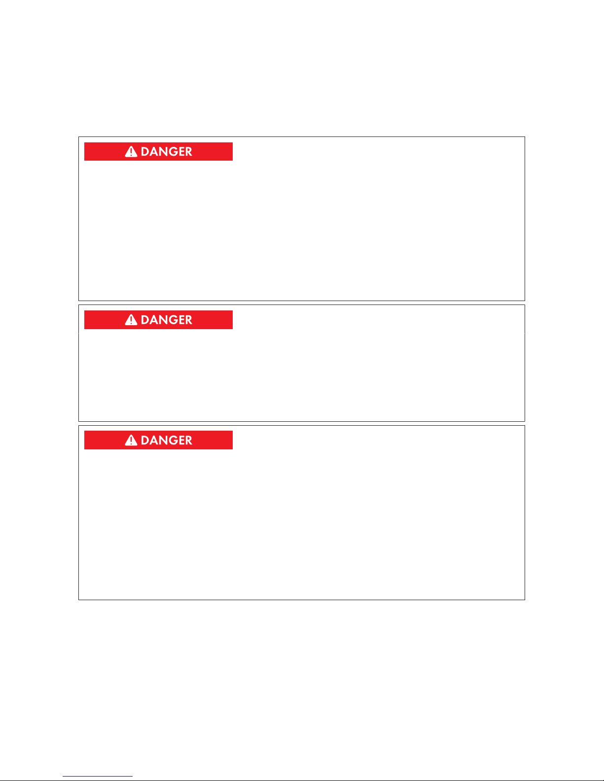
Danger to life from electric shock due to live voltage
High voltages are present in the live components of the product. Touching live components results
in death or serious injury due to electric shock.
• Wear suitable personal protective equipment for all work on the product.
• Do not touch any live components.
• Unless live voltage is absolutely necessary, always disconnect the product from voltage
sources before performing any work (see Section8 "Disconnecting and Reconnecting",
page47).
Danger to life from electric shock due to live DC cables
DC cables connected to PV modules that are exposed to sunlight are energized. Touching live
cables results in death or serious injury due to electric shock.
• Prior to assembling the DC cables, ensure that the DC cables are voltage-free.
• Wear suitable personal protective equipment for all work on the product.
Danger to life from electric shock due to damaged product
Operating a damaged product can lead to hazardous situations that result in death or serious
injuries due to electric shock.
• Only operate the product when it is in a flawless technical condition and safe to operate.
• Check the product regularly for visible damage.
• Make sure that all external safety equipment is freely accessible at all times.
• Make sure that all safety equipment is in good working order.
• Wear suitable personal protective equipment for all work on the product.
2 Safety
SMA Solar Technology AG
Operating Manual 9SSMUXX1015-BE-en-14
Danger to life from electric shock if the product is not locked
If the product is not locked, unauthorized persons will have access to live components carrying
lethal voltages. Touching live components can result in death or serious injury due to electric
shock.
• Always close and lock the product.
• Remove the keys.
• Store the keys in a safe place.
• Ensure that no unauthorized persons have access to the closed electrical operating area.
Danger to life from electric shock if the DC load-break switch is damaged
Switching the DC load-break switch at temperatures belowthe specified threshold may damage
the DC load-break switch. The threshold is: ‒25°C. In this case, reliable disconnection can no
longer be guaranteed.
If the DC load-break switch is switched in spite of visible damage, again the reliable
disconnection function cannot be guaranteed.
High voltages are present in components that are not properly disconnected. Touching live
components can result in death or serious injury due to electric shock.
• Do not switch the DC load-break switch at temperatures below the specified threshold. The
threshold is: ‒25°C.
• Do not switch the DC load-break switch if it is visibly damaged.
Damage to the PV system due to incorrectly rated fuses
If fuses are incorrectly rated, excessive reverse currents can destroy the PV modules.
• Observe the maximum current values for the product when rating the fuses.
2 Safety
SMA Solar Technology AG
Operating ManualSSMUXX1015-BE-en-1410
Property damage due to dust intrusion and moisture penetration
Dust or moisture intrusion can damage the product and impair its functionality.
• Do not open the enclosure during rainfall or when humidity exceeds the specified threshold.
The threshold for humidity is: 95 %.
• Only perform maintenance work when the environment is dry and free of dust.
• Operation of the product is only permitted when it is closed.
• If the installation or commissioning process is interrupted, mount all panels.
• Close and lock the enclosure.
• The product must always be closed for storage.
• Store the product in a dry and covered location.
• Temperature at the storage location must be in the specified range. The temperature range
is: ‒40°C to +70°C.
Damage to electronic components due to electrostatic discharge
Electrostatic discharge can damage or destroy electronic components.
• Observe the ESD safety regulations when working on the product.
• Wear suitable personal protective equipment for all work on the product.
• Discharge electrostatic charge by touching grounded elements. Only then is it safe to touch
electronic components.
2.3 Personal Protective Equipment
Always wear suitable protective equipment
When working on the product, always wear the appropriate personal protective equipment
for the specific job.
The following personal protective equipment is regarded to be the minimum requirement:
☐ In a dry environment, safety shoes of categoryS3 with perforation-proof soles and steel toe
caps
☐ During precipitation or on moist ground, safety boots of categoryS5 with perforation-proof
soles and steel toe caps
☐ Tight-fitting work clothes made of 100%cotton
☐ Suitable work pants
☐ Individually fitted hearing protection
☐ Safety gloves
Any other prescribed protective equipment must also be used.
2 Safety
SMA Solar Technology AG
Operating Manual 11SSMUXX1015-BE-en-14
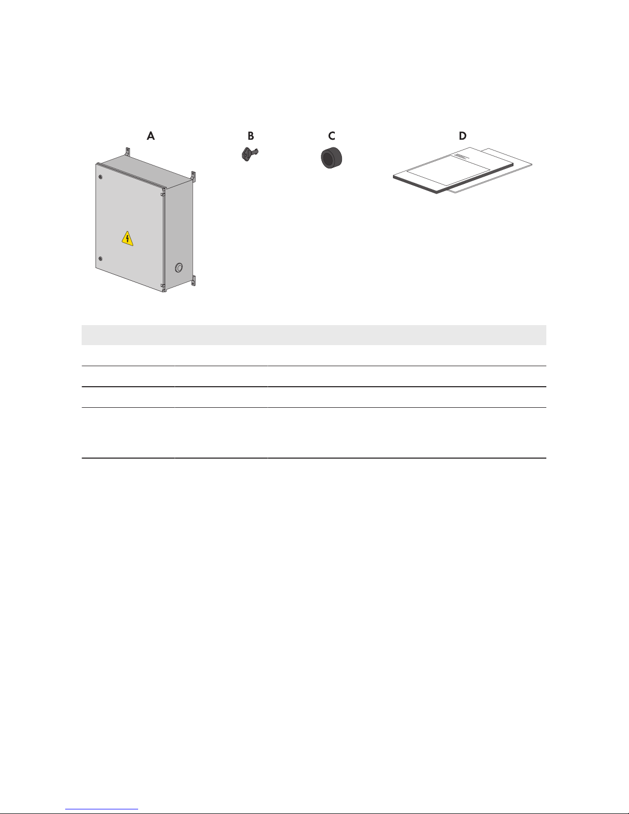
3 Scope of Delivery
Check the scope of delivery for completeness and any externally visible damage. Contact your
distributor if the scope of delivery is incomplete or damaged.
Figure 1: Components included in the scope of delivery
Position Quantity Designation
A 1 SMAString-Monitor
B 1 Switch cabinet key
C 4 Size-reducing seal inserts
D 1 Operating manual, circuit diagram, installation manual for
inline fuse connector and installation manual for PV connector
3 Scope of Delivery
SMA Solar Technology AG
Operating ManualSSMUXX1015-BE-en-1412
4 Product Overview
4.1 SMAString-Monitor
The SMAString‑Monitor is a PV array junction box to which several strings can be connected in
parallel. The SMAString‑Monitor can be operated in large-scale PV power plants with central
inverters from SMA Solar Technology AG or other PV inverters.
The essential tasks performed by the SMAString-Monitor are:
• to bundle the input currents of the strings
• Measuring of the input currents of the strings and transfer to the inverter
• to transmit information on the input currents of the strings
This enables failures to be recognized and power and yield losses to be minimized.
A distinction is made for the following SMA String-Monitor types:
Device types for rated voltage 1,000V
DC
Device types for rated voltage 1,500V
DC
Number of string inputs per
potential
SSM-U-1610 SSM-U-1615 16
SSM-U-2410 SSM-U-2415 24
SSM-U-3210 SSM-U-2415 32
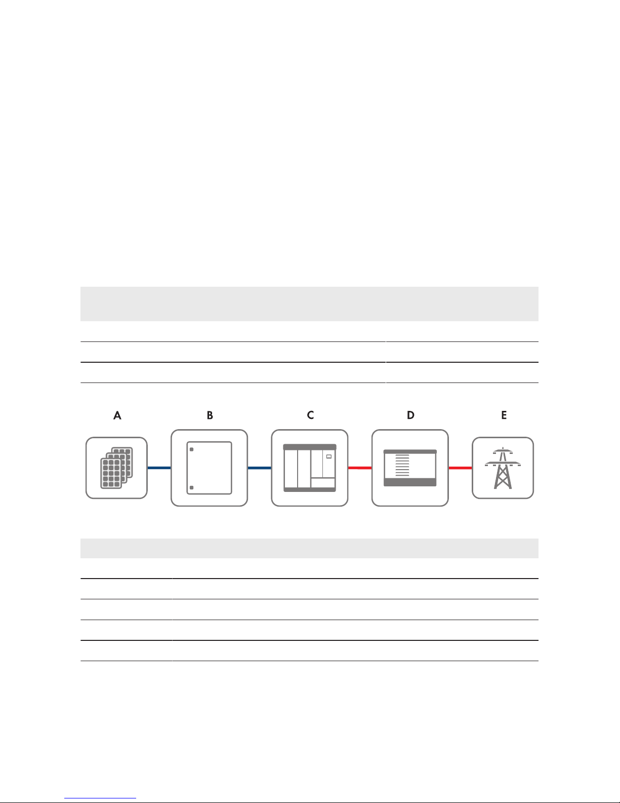
Principle of a grid-tie PV system with SMAString-Monitor
Figure 2: Principle of a grid-tie PV system with SMAString-Monitor
Position Designation
A PV array
B SMAString-Monitor
C Sunny Central
D Transformer
E Utility grid
4 Product Overview
SMA Solar Technology AG
Operating Manual 13SSMUXX1015-BE-en-14
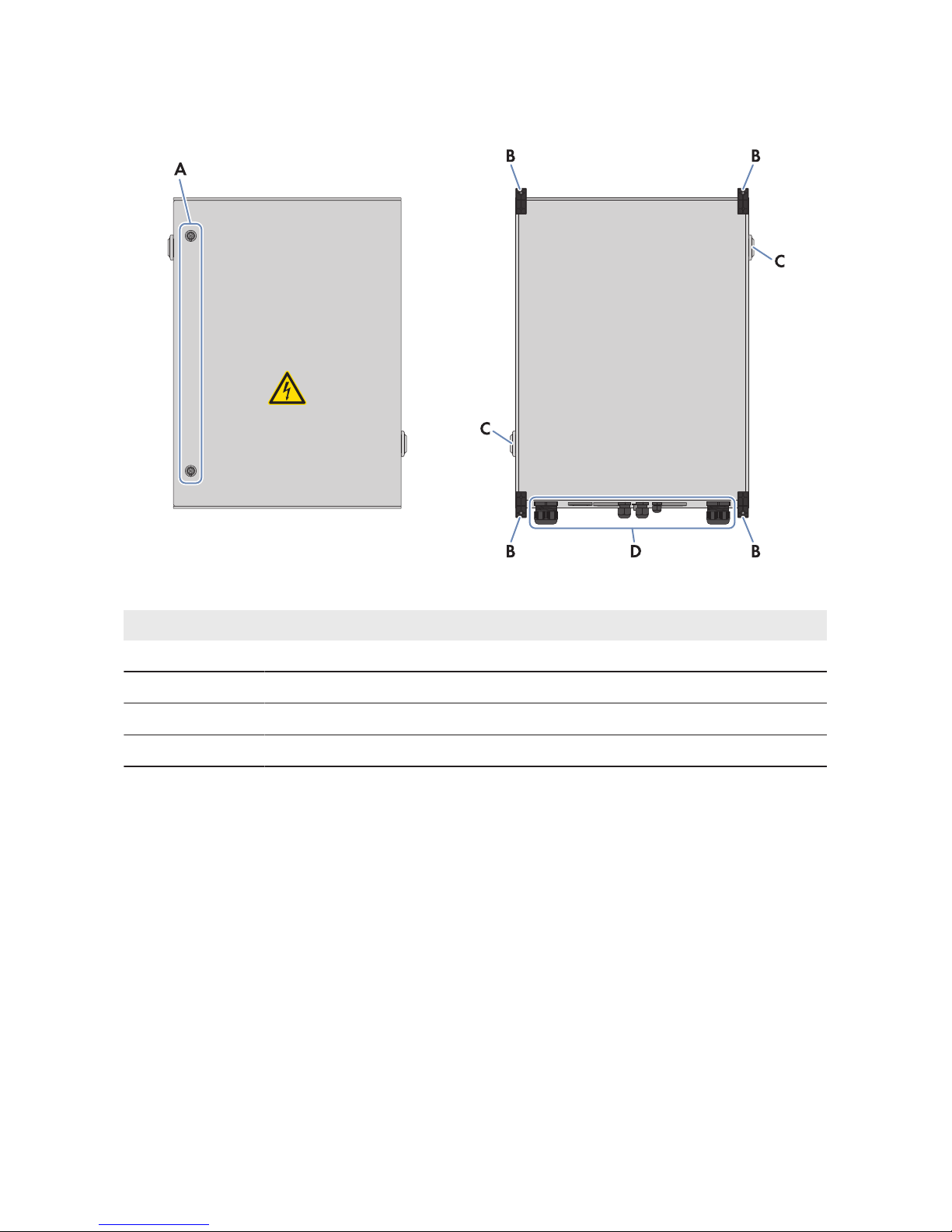
4.2 External View of the DC Subdistribution
Figure 3: External view of the DC subdistribution
Position Designation
A Lock cylinder
B Wall bracket lugs
C Vent plug
D Enclosure openings for introducing the cables
4 Product Overview
SMA Solar Technology AG
Operating ManualSSMUXX1015-BE-en-1414
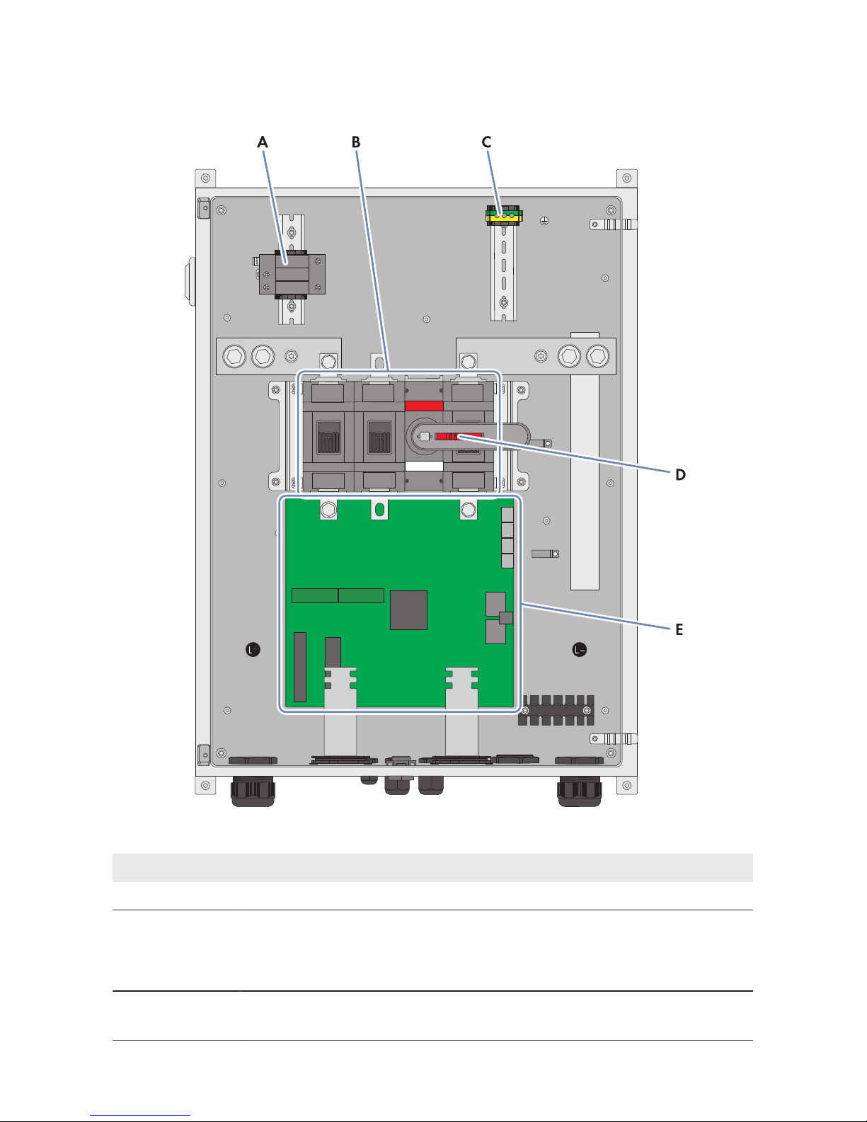
4.3 Components of the DC Subdistribution
Figure 4: Components of the DC subdistribution (SSM-U-1615 / SSM-U-2415 / SSM-U-3215)
Position Designation
A DC overvoltage protection
B DC load-break switch
• 2-pole at SSM-U-1610 / SSM-U-2410 / SSM-U-3210
• 3-pole at bei SSM-U-1615 / SSM-U-2415 / SSM-U-3215
C Terminal for connection of the DC overvoltage protection unit to the functional
grounding
4 Product Overview
SMA Solar Technology AG
Operating Manual 15SSMUXX1015-BE-en-14
Position Designation
D Rotary handle of the DC load-break switch
E Electronic assembly
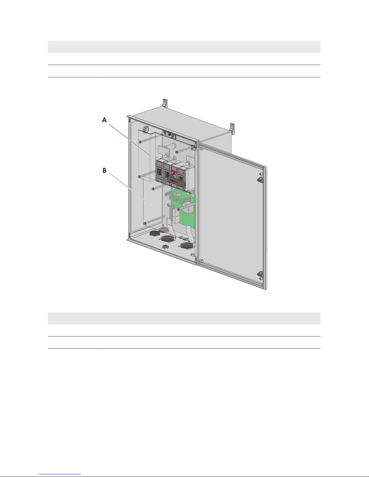
Protective covers
Figure 5: Position of the protective covers
Position Designation
A Top protective cover
B Bottom protective cover
4 Product Overview
SMA Solar Technology AG
Operating ManualSSMUXX1015-BE-en-1416
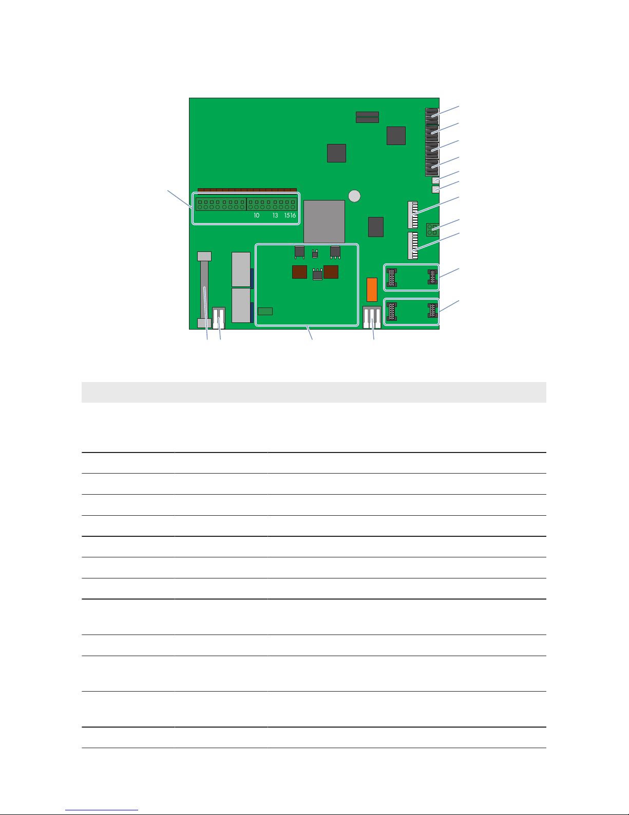
4.4 Terminals on the Electronic Assembly
12 345678 9 1112 14
A
B
C
D
E
F
G
H
K
L
M
N
OP
Q
I
Figure 6: Terminals on the electronic assembly
Position Designation Explanation
A ‒ Connection of string cable harnesses (PV+) and, depend-
ing on the version, of the plug-in board (MEU) for the num-
ber of PV inputs (factory installed)
B X1 Analog current input
C X2 Analog input temperature sensor external 1 (EXT 1)
D X3 Analog input temperature sensor external 2 (EXT 2)
E X4 Digital customer input
F X5 Digital input surge arrester DC
G X6 Status alarm contact DC load-break switch
H X7 Ethernet communication output LAN OUT
I X8 Terminal for the functional grounding cable of the elec-
tronic assembly
K X9 Ethernet communication input LAN IN
L LWLPB 1 Slot for the OF interface module (communication input
LWL IN)
M LWLPB 2 Slot for the OF interface module (communication output
LWL OUT)
N X10 Digital output of potential-free change-over contact
4 Product Overview
SMA Solar Technology AG
Operating Manual 17SSMUXX1015-BE-en-14

Position Designation Explanation
O ‒ Slot for the power supply assembly for external 230V
AC
supply voltage to the SMAString-Monitor via the inverter
P X14 Terminal for supply voltage of the SMAString-Monitor
from the PV field (PV-) (factory installed)
Q ‒ Fuse for the supply voltage of the SMAString-Monitor
from the PV field
4.5 Type Label
The type label clearly identifies the product.
You will require the information on the type label to use the product safely and when seeking
customer support from Service (see Section15, page75). The type label must remain
permanently attached to the product.
SMAString-Monitor
There are two type labels attached to the SMAString‑Monitor. The type labels are located on the
inside of the right-hand door and on the right-hand outside panel of the SMAString‑Monitor.
You can read off the following data from the type label:
• Date of manufacture (Fabrication Date)
• Serial number (SER)
• Device type (SSM-U-XXXX XX/XX/XX)
• Device-specific characteristics
Electronic assembly
There is one type label attached to the electronic assembly. The type label is located at the top left
of the electronic assembly.
You can read off the following data from the type label:
• Production version (FA)
• Serial number (SER)
• Assembly type and version (SSM30BASE.XXX)
Plug-in board (MEU) for the number of PV inputs
There is one type label attached to the plug-in board.
You can read off the following data from the type label:
• Production version (FA)
• Serial number (SER)
• Assembly type and version (SSM30MEU.XXX)
4 Product Overview
SMA Solar Technology AG
Operating ManualSSMUXX1015-BE-en-1418
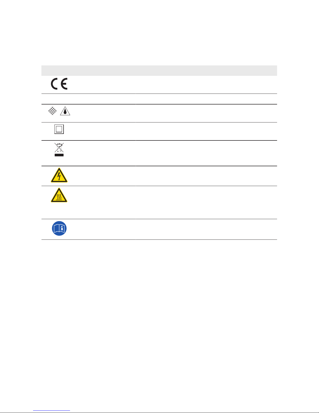
4.6 Symbols on the Product
The following gives an explanation of all the symbols found on the SMAString-Monitor and on the
type label.
Symbol Designation Explanation
CE marking The product complies with the requirements of the applica-
ble EU directives.
DataMatrix code 2Dcode for device-specific characteristics
Degree of protec-
tionIP54
The product is protected against interior dust deposits and
splashing water from all angles.
Protection class II The product has a reinforced or double insulation be-
tween grid current circuit and output voltage.
WEEE designation Do not dispose of the product together with household
waste but in accordance with the locally applicable dis-
posal regulations for electronic waste.
Beware of dangerous
voltage
The product operates at high voltages. All work on the
product must be carried out by qualified persons only.
Beware of hot surface The product can get hot during operation. Avoid contact
during operation. Allow the product to cool down suffi-
ciently before carrying out any work. Wear personal pro-
tective equipment such as safety gloves.
Observe the documentation
Observe all documentation supplied with the product.
4 Product Overview
SMA Solar Technology AG
Operating Manual 19SSMUXX1015-BE-en-14
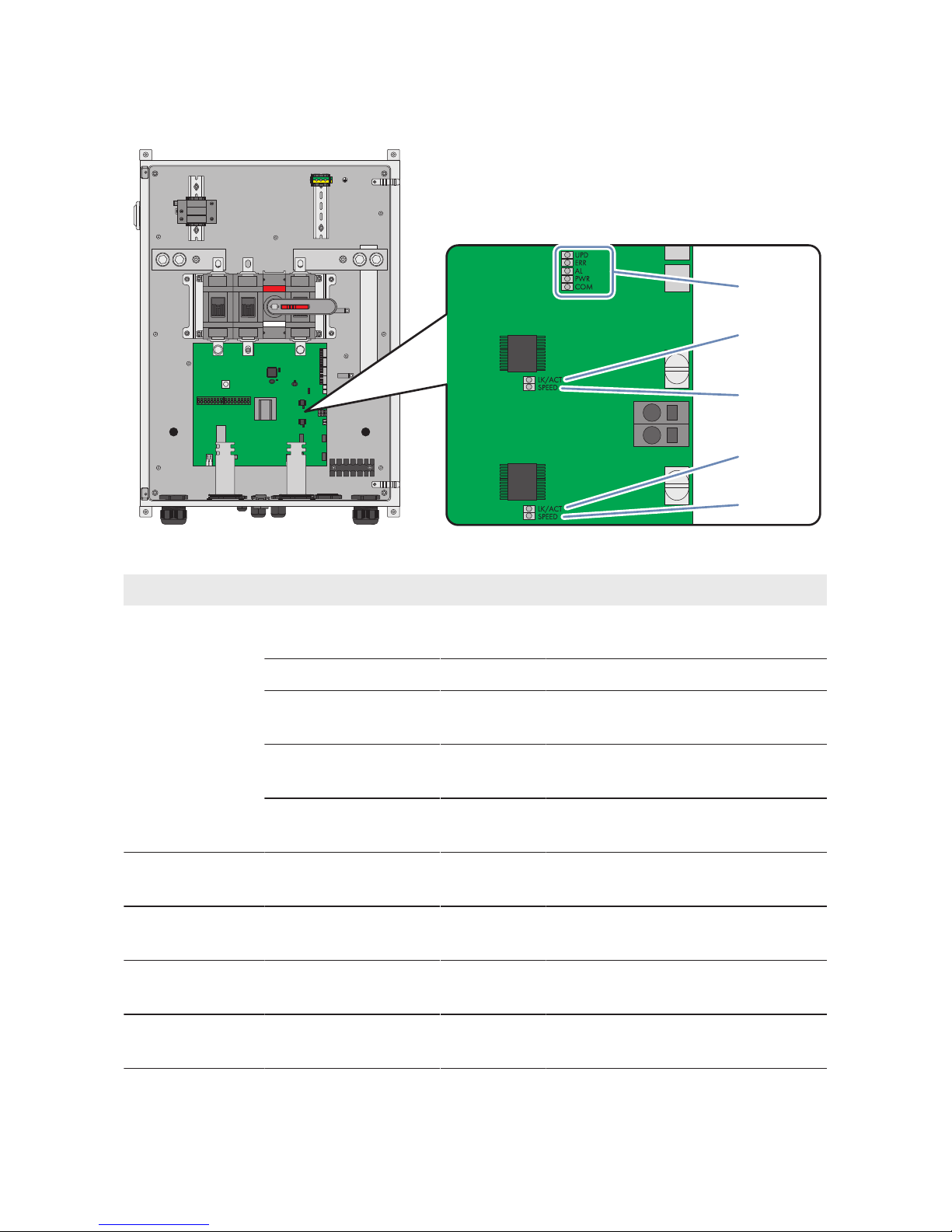
4.7 LEDs on the Electronic Assembly
L‒L+
LK/ACT
SPEED
LK/ACT
SPEED
UPD
ERR
AL
PWR
COM
A
B
C
D
E
Figure 7: LEDs on the electronic assembly
Position Designation Color Explanation
A UPD yellow Update status of the SMAString-Moni-
tor
ERR red Error in the SMAString-Monitor
AL green Firmware status of the SMAString-
Monitor
PWR green Voltage supply status of the
SMAString-Monitor
COM yellow Communication status of the
SMAString-Monitor
B LK/ACT green Status/activity of the network connec-
tion at the communication output
C SPEED yellow Speed of the network connection at
the communication output
D LK/ACT green Status/activity of the network connec-
tion at the communication input
E SPEED yellow Speed of the network connection at
the communication input
A description of the LED states will by given in (see Section9.1, page50).
4 Product Overview
SMA Solar Technology AG
Operating ManualSSMUXX1015-BE-en-1420
5 Mounting
5.1 Selecting the Mounting Location
Fire hazard due to wrong choice of mounting location
Despite careful construction, electrical devices can cause fires.
• Do not mount the DC sub-distribution on flammable construction materials.
• Do not mount the DC sub-distribution in areas containing highly flammable materials.
• Do not mount the DC sub-distribution in potentially explosive atmospheres.
Requirements for the mounting location:
☐ The mounting location can be outdoors or indoors.
☐ The mounting location must not be in a living or office area.
☐ The mounting location must not block any escape routes.
☐ The mounting location must be freely and safely accessible at all times without the necessity
for any auxiliary equipment (e.g. scaffolding or lifting platforms). Non-fulfillment of these
criteria may restrict servicing.
☐ The mounting location must be shaded, e.g. under a protective roof.
☐ The mounting location must be suitable for the weight and dimensions of the SMA
String‑Monitor.
☐ The mounting location must be suitable for the wind load.
☐ Mounting space below the SMAString-Monitor when using the inline fuse connectors:
at least 800mm.
Requirements for mounting the SMAString-Monitor
☐ Mount the SMAString-Monitor so that the connection area is facing downwards.
☐ Mount the SMAString-Monitor in a horizontal position.
☐ Do not mount the SMAString-Monitor in a twisted manner.
☐ Do not mount the SMAString‑Monitor in lying down or inclined position.
☐ An external cable support rail must be provided.
5 Mounting
SMA Solar Technology AG
Operating Manual 21SSMUXX1015-BE-en-14
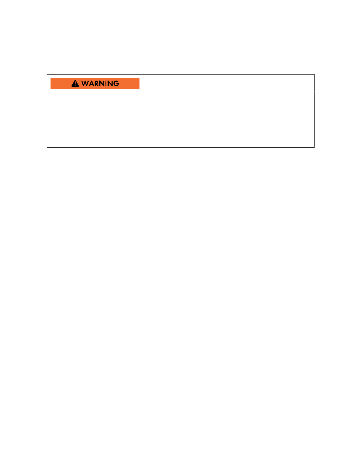
Example: Mounting on PV array substructure
• If the PV array is mounted on a free-standing
structure, the DC subdistribution can be fixed
to this structure in a shaded position. In this
case, make sure that there is no danger of
rainwater flowing off the module surface and
over the enclosure of the DC subdistribution.
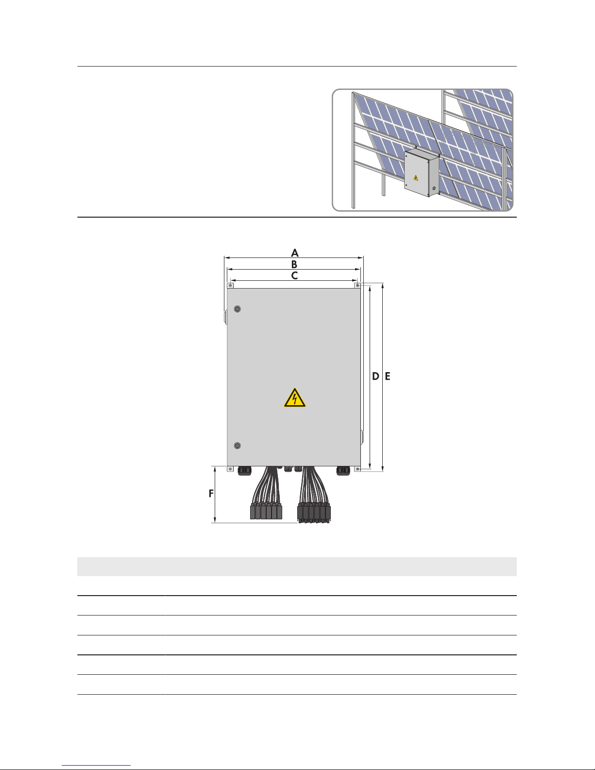
Dimensions and anchoring points:
Figure 8: Dimensions and anchoring points
Position Explanation
A 630.00mm
B 600.00mm
C 573.00mm (space between anchoring points)
D 825.60mm (space between anchoring points)
E 850.00mm
F 250.00mm
5 Mounting
SMA Solar Technology AG
Operating ManualSSMUXX1015-BE-en-1422
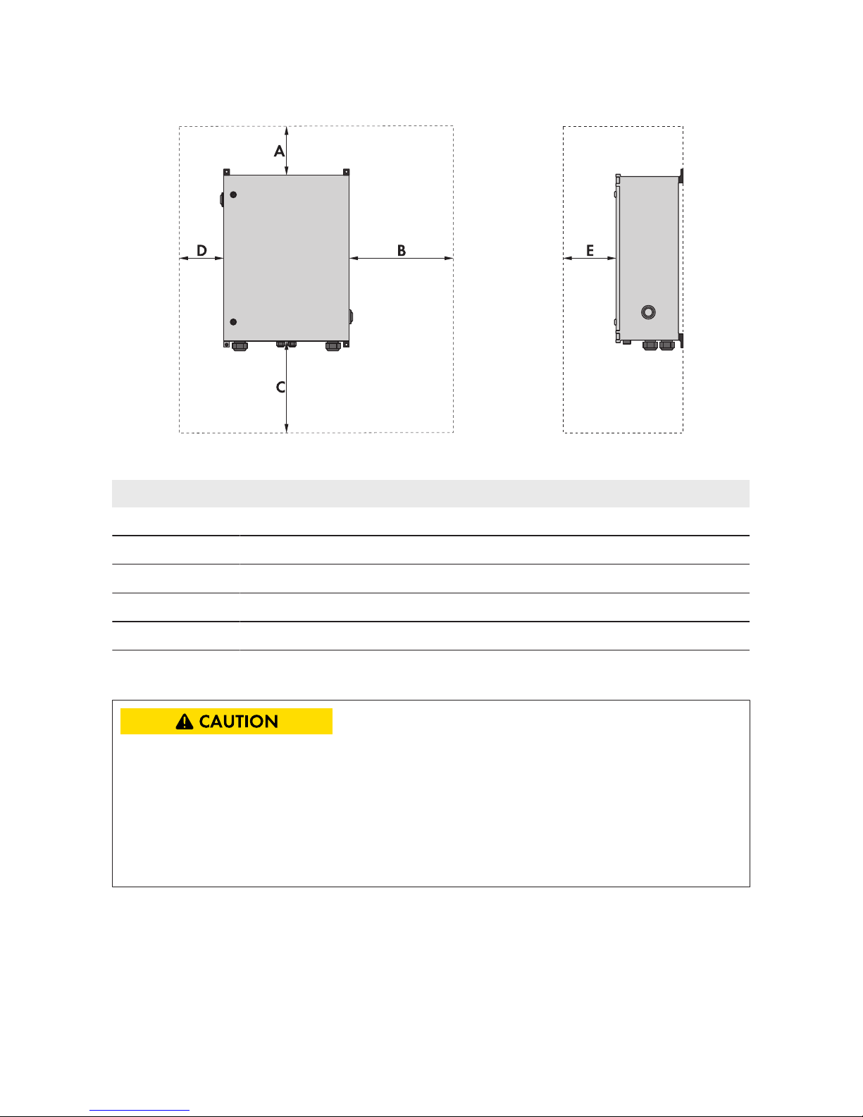
Observe minimum clearances:
Figure 9: Minimum clearances
Position Explanation
A 200mm
B 650mm
C 800mm
D 150mm
E 650mm
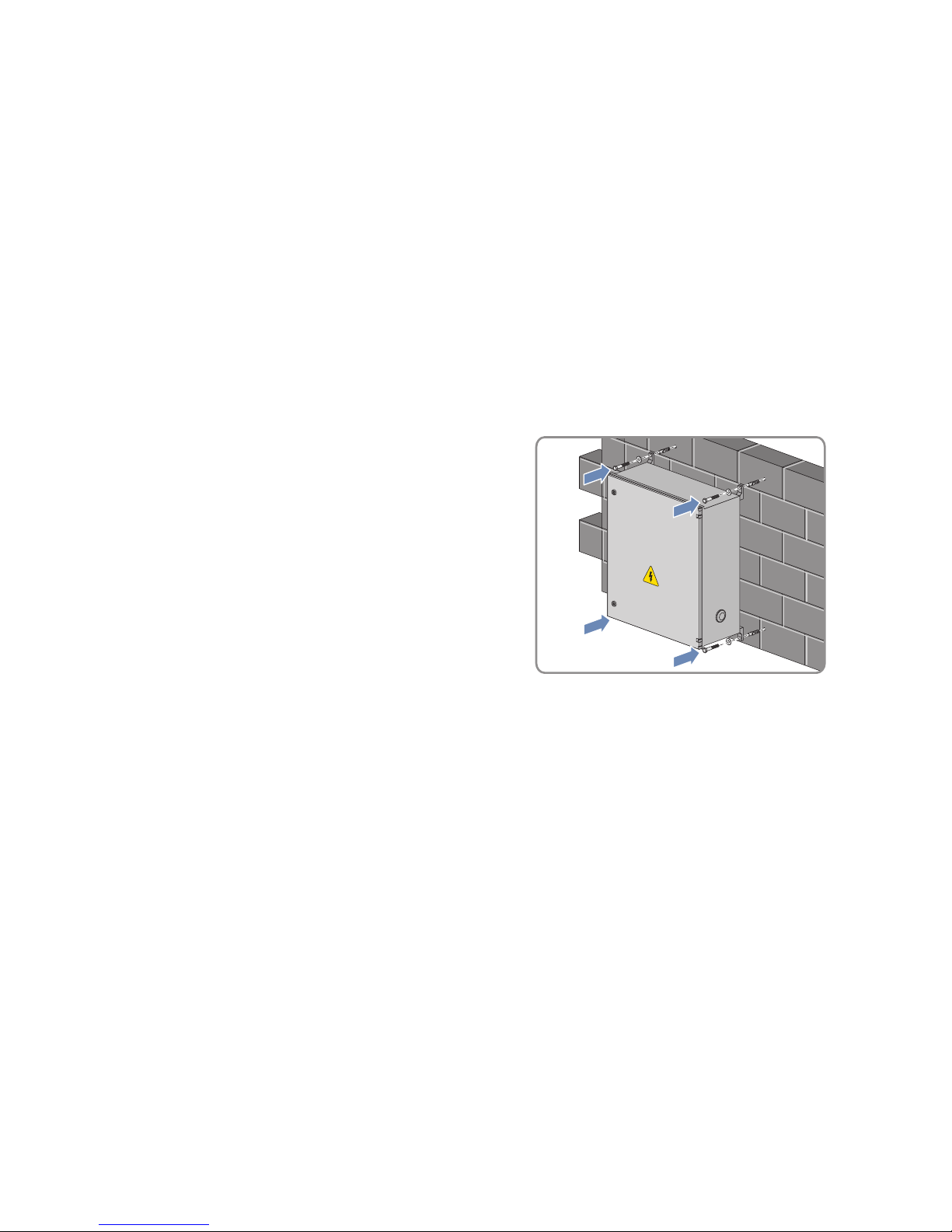
5.2 Mounting the SMAString-Monitor on the Wall
Risk of injury when lifting the DC sub-distribution, or if it is dropped
There is risk of injury if the DC sub-distribution is lifted incorrectly or dropped while being
transported or when attaching it to or removing it from the wall mounting bracket. Weight of the
DC sub-distribution without installed accessories: 35 kg.
• Two persons are required for mounting and disassembling the DC sub-distribution.
• Carefully lift and transport the DC sub-distribution.
Additionally required mounting material (not included in the scope of delivery):
• For mounting the DC subdistribution on a wall:
– 4 screws M6. Take the wall properties into account when selecting the screws.
– 4 washers
5 Mounting
SMA Solar Technology AG
Operating Manual 23SSMUXX1015-BE-en-14
– 4 screw anchors if necessary. Take the wall properties into account when selecting the
screw anchors.
• For mounting the DC subdistribution on the PV module substructure:
– 4 screws M6
– 4 washers
– 4 nuts
Procedure:
1. Close the DC subdistribution.
2. Mark the position of the drill holes on the wall or support structure.
3. Drill holes at the marked positions.
4. If necessary, insert screw anchors.
5. Fasten the DC subdistribution to the wall or
substructure using suitable screws and washers.
6. Ensure that the DC subdistribution is securely attached.
5 Mounting
SMA Solar Technology AG
Operating ManualSSMUXX1015-BE-en-1424
 Loading...