

Page 1

Installation Manual
SUNNY STRING-MONITOR SSM8-21-BS / SSM16-21-BS /
SSM8-21-BS-JP / SSM16-21-BS-JP
SSMxx-21-IA-BS-JP-en-20 | 98-116700.03 | Version 2.0 ENGLISH
Page 2

Legal Provisions SMA Solar Technology AG
Legal Provisions
The information contained in this document is the property of SMA Solar Technology AG. Publishing its content, either
partially or in full, requires the written permission of SMA Solar Technology AG. Any internal company copying of the
document for the purposes of evaluating the product or its correct implementation is allowed and does not require
permission.
SMA Warranty
You can download the current warranty conditions from the Internet at www.SMA-Solar.com.
Trademarks
All trademarks are recognized, even if not explicitly identified as such. A lack of identification does not mean that a
product or symbol is not trademarked.
The BLUETOOTH
marks by SMA Solar Technology AG is under license.
®
Modbus
is a registered trademark of Schneider Electric and is licensed by the Modbus Organization, Inc.
QR Code is a registered trademark of DENSO WAVE INCORPORATED.
®
Phillips
Torx
and Pozidriv® are registered trademarks of Phillips Screw Company.
®
is a registered trademark of Acument Global Technologies, Inc.
®
word mark and logos are registered trademarks owned by Bluetooth SIG, Inc. and any use of these
SMA Solar Technology AG
Sonnenallee 1
34266 Niestetal
Germany
Tel. +49 561 9522-0
Fax +49 561 9522-100
www.SMA.de
E-mail: info@SMA.de
© 2004 bis 2015 SMA Solar Technology AG. Alle Rechte vorbehalten.
2 SSMxx-21-IA-BS-JP-en-20 Installation Manual
Page 3

SMA Solar Technology AG Inhaltsverzeichnis
Inhaltsverzeichnis
1 Information on this Document. . . . . . . . . . . . . . . . . . . . . . . . . . . . . . . . . . . . . . . . . . . . . . . . . . . . . 5
2 Safety . . . . . . . . . . . . . . . . . . . . . . . . . . . . . . . . . . . . . . . . . . . . . . . . . . . . . . . . . . . . . . . . . . . . . . . . 6
2.1 Intended Use . . . . . . . . . . . . . . . . . . . . . . . . . . . . . . . . . . . . . . . . . . . . . . . . . . . . . . . . . . . . . . . . . . . . . . . . . 6
2.2 Safety Information . . . . . . . . . . . . . . . . . . . . . . . . . . . . . . . . . . . . . . . . . . . . . . . . . . . . . . . . . . . . . . . . . . . . . 7
3 Scope of Delivery. . . . . . . . . . . . . . . . . . . . . . . . . . . . . . . . . . . . . . . . . . . . . . . . . . . . . . . . . . . . . . 10
4 Product Description . . . . . . . . . . . . . . . . . . . . . . . . . . . . . . . . . . . . . . . . . . . . . . . . . . . . . . . . . . . . 11
4.1 Sunny String-Monitor . . . . . . . . . . . . . . . . . . . . . . . . . . . . . . . . . . . . . . . . . . . . . . . . . . . . . . . . . . . . . . . . . . 11
4.2 String-Current Monitoring . . . . . . . . . . . . . . . . . . . . . . . . . . . . . . . . . . . . . . . . . . . . . . . . . . . . . . . . . . . . . . . 12
4.3 DC Load-Break Switch . . . . . . . . . . . . . . . . . . . . . . . . . . . . . . . . . . . . . . . . . . . . . . . . . . . . . . . . . . . . . . . . . 14
4.4 String Fuses. . . . . . . . . . . . . . . . . . . . . . . . . . . . . . . . . . . . . . . . . . . . . . . . . . . . . . . . . . . . . . . . . . . . . . . . . . 15
4.5 Overvoltage Protection. . . . . . . . . . . . . . . . . . . . . . . . . . . . . . . . . . . . . . . . . . . . . . . . . . . . . . . . . . . . . . . . . 15
4.6 LEDs on the String-Monitor Unit . . . . . . . . . . . . . . . . . . . . . . . . . . . . . . . . . . . . . . . . . . . . . . . . . . . . . . . . . . 16
4.7 Type Label . . . . . . . . . . . . . . . . . . . . . . . . . . . . . . . . . . . . . . . . . . . . . . . . . . . . . . . . . . . . . . . . . . . . . . . . . . 16
5 Mounting. . . . . . . . . . . . . . . . . . . . . . . . . . . . . . . . . . . . . . . . . . . . . . . . . . . . . . . . . . . . . . . . . . . . . 18
5.1 Wall Mounting . . . . . . . . . . . . . . . . . . . . . . . . . . . . . . . . . . . . . . . . . . . . . . . . . . . . . . . . . . . . . . . . . . . . . . . 18
5.1.1 Selecting the Mounting Location . . . . . . . . . . . . . . . . . . . . . . . . . . . . . . . . . . . . . . . . . . . . . . . . . . . . . . . . . . . .18
5.1.2 Mounting the Sunny String-Monitor. . . . . . . . . . . . . . . . . . . . . . . . . . . . . . . . . . . . . . . . . . . . . . . . . . . . . . . . . .18
5.2 Base Mounting . . . . . . . . . . . . . . . . . . . . . . . . . . . . . . . . . . . . . . . . . . . . . . . . . . . . . . . . . . . . . . . . . . . . . . . 20
5.2.1 Selecting the Mounting Location . . . . . . . . . . . . . . . . . . . . . . . . . . . . . . . . . . . . . . . . . . . . . . . . . . . . . . . . . . . .20
5.2.2 Mounting the Base. . . . . . . . . . . . . . . . . . . . . . . . . . . . . . . . . . . . . . . . . . . . . . . . . . . . . . . . . . . . . . . . . . . . . . .20
5.2.3 Mounting the Sunny String-Monitor on the Base . . . . . . . . . . . . . . . . . . . . . . . . . . . . . . . . . . . . . . . . . . . . . . . .21
6 Electrical Connection . . . . . . . . . . . . . . . . . . . . . . . . . . . . . . . . . . . . . . . . . . . . . . . . . . . . . . . . . . . 23
6.1 Safety during Electrical Connection . . . . . . . . . . . . . . . . . . . . . . . . . . . . . . . . . . . . . . . . . . . . . . . . . . . . . . . 23
6.2 Inserting the Cables into the Switch Cabinet . . . . . . . . . . . . . . . . . . . . . . . . . . . . . . . . . . . . . . . . . . . . . . . . 23
6.3 Overview of the Connection Area . . . . . . . . . . . . . . . . . . . . . . . . . . . . . . . . . . . . . . . . . . . . . . . . . . . . . . . . 25
6.3.1 SSM8-21-BS/SSM16-21-BS . . . . . . . . . . . . . . . . . . . . . . . . . . . . . . . . . . . . . . . . . . . . . . . . . . . . . . . . . . . . . . .25
6.3.2 SSM8-21-BS-JP/SSM16-21-BS-JP . . . . . . . . . . . . . . . . . . . . . . . . . . . . . . . . . . . . . . . . . . . . . . . . . . . . . . . . . . .26
6.4 Connecting the String Cables. . . . . . . . . . . . . . . . . . . . . . . . . . . . . . . . . . . . . . . . . . . . . . . . . . . . . . . . . . . . 26
6.5 Connecting the DC Main Cables . . . . . . . . . . . . . . . . . . . . . . . . . . . . . . . . . . . . . . . . . . . . . . . . . . . . . . . . . 27
6.5.1 Cable Requirements. . . . . . . . . . . . . . . . . . . . . . . . . . . . . . . . . . . . . . . . . . . . . . . . . . . . . . . . . . . . . . . . . . . . . .27
6.5.2 Connecting DC Main Cables to the Busbar . . . . . . . . . . . . . . . . . . . . . . . . . . . . . . . . . . . . . . . . . . . . . . . . . . .28
6.5.3 Connecting DC Main Cables to the Terminals . . . . . . . . . . . . . . . . . . . . . . . . . . . . . . . . . . . . . . . . . . . . . . . . .29
6.6 Connecting the Grounding Cable . . . . . . . . . . . . . . . . . . . . . . . . . . . . . . . . . . . . . . . . . . . . . . . . . . . . . . . . 30
6.6.1 Connecting the Grounding Cable in the SSMxx21-BS . . . . . . . . . . . . . . . . . . . . . . . . . . . . . . . . . . . . . . . . . . .30
6.6.2 Connecting the Grounding Cable in the SSMxx21-BS-JP . . . . . . . . . . . . . . . . . . . . . . . . . . . . . . . . . . . . . . . . .31
6.7 Connecting the Data Cables . . . . . . . . . . . . . . . . . . . . . . . . . . . . . . . . . . . . . . . . . . . . . . . . . . . . . . . . . . . . 31
6.7.1 Cable Requirements. . . . . . . . . . . . . . . . . . . . . . . . . . . . . . . . . . . . . . . . . . . . . . . . . . . . . . . . . . . . . . . . . . . . . .31
6.7.2 Connecting the Data Cables in the SSMxx-21-BS. . . . . . . . . . . . . . . . . . . . . . . . . . . . . . . . . . . . . . . . . . . . . . .31
6.7.3 Connecting the Data Cable in the SSMxx-21-BS-JP . . . . . . . . . . . . . . . . . . . . . . . . . . . . . . . . . . . . . . . . . . . . .34
6.7.4 Connecting the Data Cables in the Sunny Central . . . . . . . . . . . . . . . . . . . . . . . . . . . . . . . . . . . . . . . . . . . . . .37
7 Commissioning . . . . . . . . . . . . . . . . . . . . . . . . . . . . . . . . . . . . . . . . . . . . . . . . . . . . . . . . . . . . . . . . 38
7.1 Safety during Commissioning . . . . . . . . . . . . . . . . . . . . . . . . . . . . . . . . . . . . . . . . . . . . . . . . . . . . . . . . . . . . 38
Installation Manual SSMxx-21-IA-BS-JP-en-20 3
Page 4

Inhaltsverzeichnis SMA Solar Technology AG
7.2 Commissioning the Sunny String-Monitor. . . . . . . . . . . . . . . . . . . . . . . . . . . . . . . . . . . . . . . . . . . . . . . . . . . 38
7.2.1 Requirements for Commissioning. . . . . . . . . . . . . . . . . . . . . . . . . . . . . . . . . . . . . . . . . . . . . . . . . . . . . . . . . . . .38
7.2.2 Terminating the Data Cable. . . . . . . . . . . . . . . . . . . . . . . . . . . . . . . . . . . . . . . . . . . . . . . . . . . . . . . . . . . . . . . .38
7.2.3 Noting Down the Serial Number of the String-Monitor Unit . . . . . . . . . . . . . . . . . . . . . . . . . . . . . . . . . . . . . . .40
7.3 Switching On the Sunny String-Monitor . . . . . . . . . . . . . . . . . . . . . . . . . . . . . . . . . . . . . . . . . . . . . . . . . . . . 40
8 Disconnecting the Sunny String-Monitor. . . . . . . . . . . . . . . . . . . . . . . . . . . . . . . . . . . . . . . . . . . .41
9 Troubleshooting . . . . . . . . . . . . . . . . . . . . . . . . . . . . . . . . . . . . . . . . . . . . . . . . . . . . . . . . . . . . . . .42
10 Maintenance . . . . . . . . . . . . . . . . . . . . . . . . . . . . . . . . . . . . . . . . . . . . . . . . . . . . . . . . . . . . . . . . . .43
10.1 Maintenance Interval . . . . . . . . . . . . . . . . . . . . . . . . . . . . . . . . . . . . . . . . . . . . . . . . . . . . . . . . . . . . . . . . . . 43
10.2 Overview of the Main Components. . . . . . . . . . . . . . . . . . . . . . . . . . . . . . . . . . . . . . . . . . . . . . . . . . . . . . . 43
10.3 Checking the Mounting Location and the Installation . . . . . . . . . . . . . . . . . . . . . . . . . . . . . . . . . . . . . . . . . 45
10.4 Checking the Enclosure . . . . . . . . . . . . . . . . . . . . . . . . . . . . . . . . . . . . . . . . . . . . . . . . . . . . . . . . . . . . . . . . 45
10.5 Checking the Inside of the Enclosure . . . . . . . . . . . . . . . . . . . . . . . . . . . . . . . . . . . . . . . . . . . . . . . . . . . . . . 45
10.6 Checking the Base Plate. . . . . . . . . . . . . . . . . . . . . . . . . . . . . . . . . . . . . . . . . . . . . . . . . . . . . . . . . . . . . . . . 45
10.7 Checking the Covers and Labels . . . . . . . . . . . . . . . . . . . . . . . . . . . . . . . . . . . . . . . . . . . . . . . . . . . . . . . . . 46
10.8 Checking the Fuse Holders . . . . . . . . . . . . . . . . . . . . . . . . . . . . . . . . . . . . . . . . . . . . . . . . . . . . . . . . . . . . . 47
10.9 Checking the Bolted, Clamp and Plug Connections. . . . . . . . . . . . . . . . . . . . . . . . . . . . . . . . . . . . . . . . . . . 47
10.10 Checking the Surge Arrester for the DC Main Cable. . . . . . . . . . . . . . . . . . . . . . . . . . . . . . . . . . . . . . . . . 47
10.11 Checking the Surge Arrester for RS485 Communication . . . . . . . . . . . . . . . . . . . . . . . . . . . . . . . . . . . . . . 48
10.12 Checking the Supply Voltage. . . . . . . . . . . . . . . . . . . . . . . . . . . . . . . . . . . . . . . . . . . . . . . . . . . . . . . . . . . 48
10.13 Checking the Ground Connection . . . . . . . . . . . . . . . . . . . . . . . . . . . . . . . . . . . . . . . . . . . . . . . . . . . . . . . 49
10.14 Checking the LEDs of the String-Monitor Unit. . . . . . . . . . . . . . . . . . . . . . . . . . . . . . . . . . . . . . . . . . . . . . . 49
11 Decommissioning . . . . . . . . . . . . . . . . . . . . . . . . . . . . . . . . . . . . . . . . . . . . . . . . . . . . . . . . . . . . . .50
11.1 Disassembling the Sunny String-Monitor . . . . . . . . . . . . . . . . . . . . . . . . . . . . . . . . . . . . . . . . . . . . . . . . . . . 50
11.2 Disposing of the Sunny String-Monitor. . . . . . . . . . . . . . . . . . . . . . . . . . . . . . . . . . . . . . . . . . . . . . . . . . . . . 50
12 Technical Data. . . . . . . . . . . . . . . . . . . . . . . . . . . . . . . . . . . . . . . . . . . . . . . . . . . . . . . . . . . . . . . . .51
13 Contact. . . . . . . . . . . . . . . . . . . . . . . . . . . . . . . . . . . . . . . . . . . . . . . . . . . . . . . . . . . . . . . . . . . . . . .55
4 SSMxx-21-IA-BS-JP-en-20 Installation Manual
Page 5

SMA Solar Technology AG 1 Information on this Document
'$1*(5
:$5 1,1*
&$87,21
/05*$&
1 Information on this Document
Validity
This document is valid for the following device types from the indicated production version:
Device type From production version
SSM8-21-BS B4
SSM16-21-BS B4
SSM8-21-BS-JP A1
SSM16-21-BS-JP A1
Target Group
The activities described in this document must only be performed by qualified persons. Qualified persons must have the
following skills:
• Knowledge of how the device works and is operated
• Training in how to deal with the dangers and risks associated with installing and using electrical devices and
installations
• Training in the installation and commissioning of electrical devices
• Knowledge of all applicable standards and directives
• Knowledge of and compliance with this document and all safety information
Additional Information
Links to additional information can be found at www.SMA-Solar.com:
Document title Document type
Product Details - Features and Mounting Options for SUNNY
STRING-MONITOR SSM8-21-BS /SSM16-21-BS/SSM8-21-BS-JP/SSM16-21-BS-JP
Plant Communication in Large-Scale PV Power Plants Technical Information
SUNNY CENTRAL - Operating Manual Operating Manual
Technical Information
Symbols
Symbol Explanation
Indicates a hazardous situation which, if not avoided, will result in death or serious injury
Indicates a hazardous situation which, if not avoided, can result in death or serious injury
Indicates a hazardous situation which, if not avoided, can result in minor or moderate injury
Indicates a situation which, if not avoided, can result in property damage
☐ Indicates a requirement for meeting a specific goal
☑ Desired result
✖ A problem that might occur
Installation Manual SSMxx-21-IA-BS-JP-en-20 5
Information that is important for a specific topic or goal, but is not safety-relevant
Page 6

2 Safety SMA Solar Technology AG
Nomenclature
In this document the device types of the Sunny String-Monitor are referred to as "Sunny String-Monitor".
2 Safety
2.1 Intended Use
The Sunny String-Monitor is a PV array junction box to which several strings can be connected in parallel. The
Sunny String-Monitor monitors the input currents of the strings and detects failures, thus helping to minimize power and
yield losses.
Figure1: Principle of a grid-tie PV system
Position Designation
A PV array
B Sunny String-Monitor
CInverter
D MV transformer
E Utility grid
The maximum current values for the Sunny String-Monitors must not be exceeded. The Sunny String-Monitor is suitable
for indoor and outdoor use.
The Sunny String-Monitor can be used in large-scale PV power plants with Sunny Central inverters. For the optimum
operation of the Sunny String-Monitor, observe the mounting location requirements (see Section12 "Technical Data",
page51).
Alterations to the product, e.g. modifications or conversions, are only permitted with the express written permission of
SMA Solar Technology AG. Unauthorized alterations will void guarantee and warranty claims and usually void the
operating license. SMA Solar Technology AG shall not be held liable for any damage caused by such changes.
Any use of the product other than that described in the Intended Use section does not qualify as appropriate.
The enclosed documentation is an integral part of this product. Keep the documentation in a convenient place for future
reference and observe all instructions contained therein.
Only use the Sunny String-Monitor in accordance with the information provided in the enclosed documentation. Any other
use can result in personal injury or property damage.
6 SSMxx-21-IA-BS-JP-en-20 Installation Manual
Page 7

SMA Solar Technology AG 2 Safety
'$1*(5
2.2 Safety Information
This section contains safety information that must be observed at all times when working on or with the product. To prevent
personal injury and property damage and to ensure long-term operation of the product, read this section carefully and
observe all safety information at all times.
Danger to life from electric shock due to live voltage
High voltages are present in the live components of the Sunny String-Monitor. Touching live components results in death
or serious injury due to electric shock.
• Wear personal protective equipment when working on the Sunny String-Monitor.
• Do not touch live components.
• Before performing any work, always disconnect the Sunny String-Monitor from voltage sources unless supply
voltage is absolutely necessary.
– Switch off the DC load-break switch in the Sunny String-Monitor.
– Remove the DC fuses in the central inverter or main DC distribution box when the power is switched off. Use the
LV/HRC fuse handle.
– Only open the fuse holders in the Sunny String-Monitor when the power is switched off.
• Ensure that the device cannot be reconnected.
• Ensure that no voltage is present.
• Ground and short-circuit the device.
• Cover or isolate any adjacent live components. Protective covers must always be mounted.
Danger to life from electric shock due to live DC cables
DC cables connected to PV modules that are exposed to sunlight are live. Touching live DC cables results in death or
serious injury due to electric shock.
• Prior to connecting the DC cables, ensure that the DC cables are voltage-free.
• Wear suitable personal protective equipment when working on the Sunny String-Monitor.
Danger to life from electric shock due to ground fault
In the event of a ground fault, grounded PV systems can still be live. Touching system components that have not been
properly grounded results in death or serious injuries from electric shock.
• Before working on the PV system, ensure that no ground fault is present.
• Wear suitable personal protective equipment for all work on the product.
Danger to life from electric shock if the Sunny String-Monitor is damaged
If the Sunny String-Monitor is damaged, dangerous situations may arise during operation that result in death or serious
injury from electric shock.
• Only use the Sunny String-Monitor when it is in a technically faultless condition and safe to operate.
• Regularly check the Sunny String-Monitor for visual damage.
• Make sure that all external safety equipment is freely accessible at all times.
• Make sure that all safety equipment is in good working order.
Installation Manual SSMxx-21-IA-BS-JP-en-20 7
Page 8

2 Safety SMA Solar Technology AG
:$5 1,1*
&$87,21
Danger to life from electric shock if the Sunny String-Monitor is left unlocked
If the Sunny String-Monitor is unlocked, unauthorized persons will have access to components carrying lethal voltages.
Touching live components can result in death or serious injury due to electric shock.
• Always lock the Sunny String-Monitor.
• Remove the keys from the door locks.
• Keep the keys in a safe place.
Risk of fire due to failure to observe torque specifications on live bolted connections
Failure to follow the specified torques reduces the ampacity of live bolted connections so that the contact resistances
increase. This can cause components to overheat and catch fire.
• Ensure that live bolted connections are always tightened with the exact torque specified in this document.
• Use suitable tools when working on the device.
• Avoid repeated tightening of live bolted connections as this may result in inadmissibly high torques.
Danger to life from electric shock if the DC load-break switch is damaged
Switching the DC load-break switch at temperatures below ‒25°C may cause damage to the DC load-break switch.
Correct disconnection function can no longer be guaranteed. High voltages are present in components that are not
properly disconnected. Touching live components can result in death or serious injury due to electric shock.
• Do not switch the DC load-break switch at temperatures below ‒25°C.
Danger to life from electric shock due to damaged fuse holders
Using the fuse holders at temperatures below ‒25°C may cause damage to the fuse holders. Correct disconnection
function can no longer be guaranteed. High voltages are present in components that are not properly disconnected.
Touching live components can result in death or serious injury due to electric shock.
• Do not use the fuse holders at temperatures below ‒25°C.
Risk of burns due to hot components or devices
Some components of the Sunny String-Monitor can get very hot during operation. Touching these components can
cause burns.
• Observe the warnings on the components.
• During operation, do not touch any components or devices marked with such warnings.
• After disconnecting the PV system from voltage sources, wait until all hot components have cooled down sufficiently.
• Wear suitable personal protective equipment for all work on the product.
8 SSMxx-21-IA-BS-JP-en-20 Installation Manual
Page 9
SMA Solar Technology AG 2 Safety
/05*$&
Damage to the PV system due to incorrectly rated fuses
If fuses are incorrectly rated, excessive reverse currents can destroy the PV modules.
• Observe the maximum current values for Sunny String-Monitors when rating the fuses.
• Only install string fuses supplied or approved by SMA Solar Technology AG for Sunny String-Monitors.
Damage to the components due to dust or moisture penetration
Dust intrusion or moisture penetration can damage the components of the Sunny String-Monitor or impair their
functionality.
• Do not open the Sunny String-Monitor during a sand storm, rainfall or humidity of more than 95%.
• Only carry out maintenance work on the Sunny String-Monitor if the environment is dry and sand-free.
• Always lock the Sunny String-Monitor.
• Always store the Sunny String-Monitor in an upright position with the connection area facing downwards.
Damage to electronic components due to electrostatic discharge
Electrostatic discharge can damage or destroy electronic components.
• When working on the Sunny String-Monitor and handling components, observe all ESD safety regulations.
• Wear suitable personal protective equipment for all work on the product.
• Discharge electrostatic charge by touching uncoated, grounded enclosure parts (e.g. at the grounding conductor
connection on the doors). Only then is it safe to touch electronic components.
Installation Manual SSMxx-21-IA-BS-JP-en-20 9
Page 10

3 Scope of Delivery SMA Solar Technology AG
3 Scope of Delivery
Check the scope of delivery for completeness and any externally visible damage. Contact your distributor if the scope of
delivery is incomplete or damaged.
Sunny String-Monitor for Wall Mounting
Figure2: Components included in the scope of delivery for wall mounting
Position Quantity Designation
A 1 Sunny String-Monitor
B 1 Switch cabinet key
C2 Wall mounting rail
D 8 Screw for the wall mounting rail
E 1 Installation manual, circuit diagram
Accessories
Fuses and cylindrical bridges are available as accessories.
10 SSMxx-21-IA-BS-JP-en-20 Installation Manual
Page 11
SMA Solar Technology AG 4 Product Description
4 Product Description
4.1 Sunny String-Monitor
The Sunny String-Monitor is a PV array junction box to which several strings can be connected in parallel. The
Sunny String-Monitor monitors the input currents of the strings and detects failures, thus helping to minimize power and
yield losses.
The string currents are monitored by the measurement PCB String-Monitor Unit (SMU) located in the
Sunny String-Monitor.
The string fuses in the Sunny String-Monitor protect the PV modules of the strings from reverse currents.
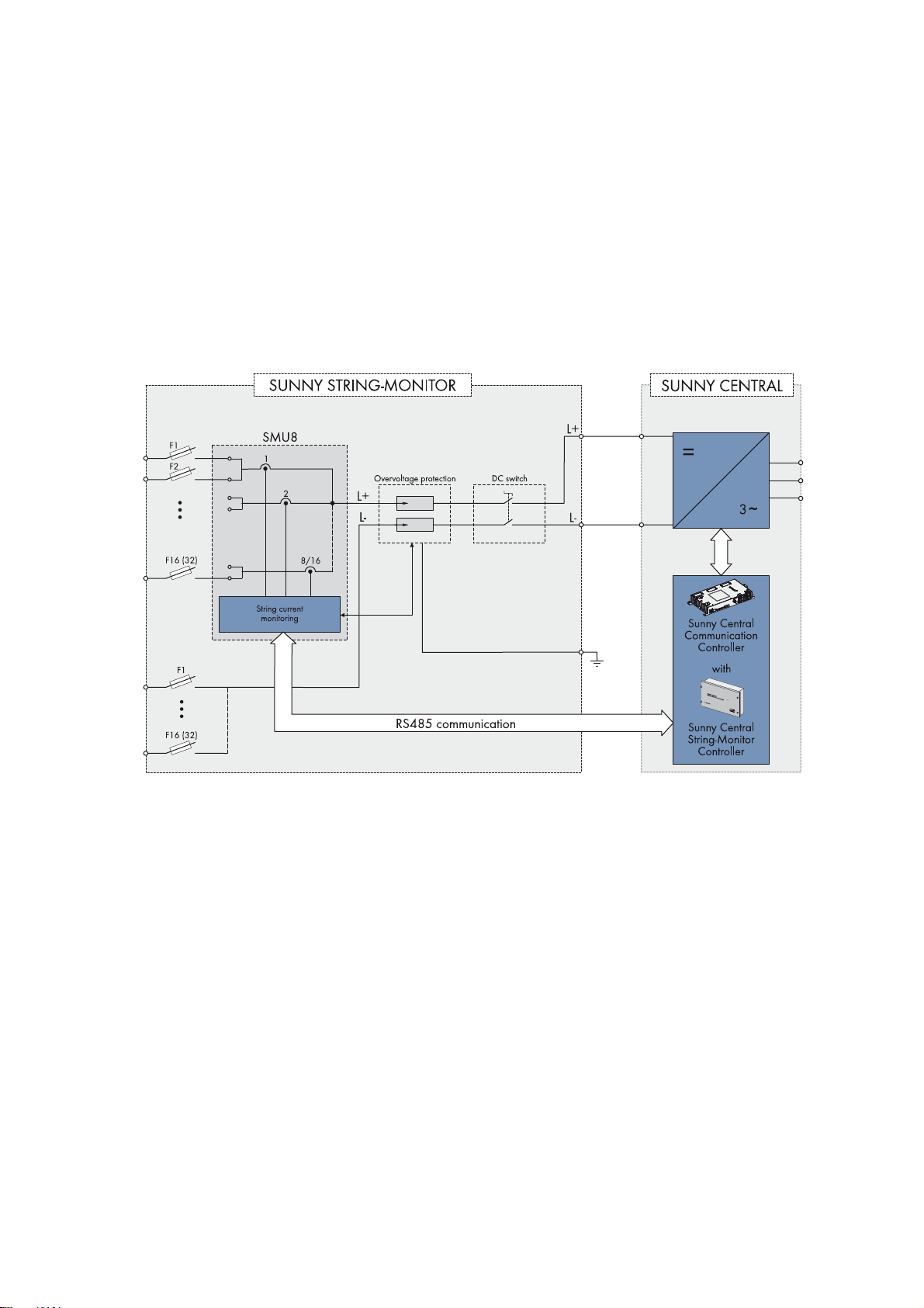
Block Circuit Diagram of the Sunny String-Monitor SSM8-21-BS/SSM16-21-BS
Figure3: Block circuit diagram of the Sunny String-Monitor SSM8-21-BS/SSM16-21-BS
Installation Manual SSMxx-21-IA-BS-JP-en-20 11
Page 12

4 Product Description SMA Solar Technology AG
Block Circuit Diagram of the Sunny String-Monitor SSM8-21-BS-JP/SSM16-21-BS-JP
Figure4: Block circuit diagram of the Sunny String-Monitor SSM8-21-BS-JP/SSM16-21-BS-JP
4.2 String-Current Monitoring
The string currents are monitored via the measurement PCB String-Monitor Unit. The String-Monitor Unit measures the
string currents and continuously calculates the mean values of the string currents. The string currents are compared with
the mean values. If a string current exceeds or falls short of the mean value by the set tolerance value, the warning 380
SMU is displayed.
With central inverters, you can use the user interface to set the parameters for the string-current monitoring and read off
the mean values (see operating manual of the respective central inverter).
The total failure of a string can be detected via the parameters set. Marginally increased string currents are reliably
detected over several query intervals and distinguished from typical current fluctuations of the PV array.
The sections below describe:
• the conditions under which the string current is monitored
• the intervals at which data is transmitted
• the key parameters for the sensitivity of the string-current monitoring.
Requirements for Activating the String-Current Monitoring
☐The DC power PDC of the PV array exceeds 5% of the nominal AC power P
P
> 0.05 * P
DC
☐ The mean value of the string currents of the individual groups l
l
M String
AC nom
≥ 0.5 A
is equal to or greater than 0.5 A.
M String
of the Sunny Central.
AC nom
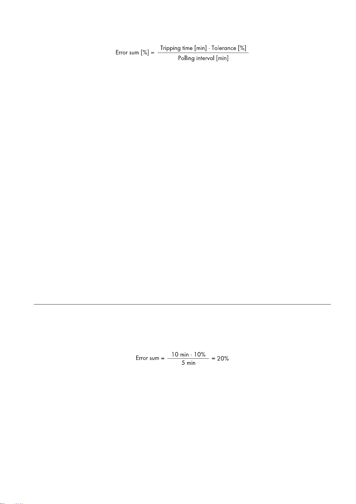
Error Sum
The error sum is a measure of the sensitivity of string-current monitoring. The error sum can be parameterized via the
tripping time and the tolerance and can be calculated using the following formula:
12 SSMxx-21-IA-BS-JP-en-20 Installation Manual
Page 13
SMA Solar Technology AG 4 Product Description
The individual error sums of the measuring channels are reset at midnight.
Query Intervals
The Sunny String-Monitor continuously measures the string currents and performs cyclic storage of the measured values.
The data logger reads out these values every five minutes.
Tripping Time
The tripping time is the time span between the occurrence of an error and the error message. The tripping time is set to
180 minutes by default. You can set the parameter for the tripping time to between 2 minutes and 1,440 minutes.
Tolerance
The tolerance indicates how much the string current is allowed to deviate from the mean value. If the string current is
outside the tolerance limits, the data logger detects the deviation and stores it. The tolerance can be set between 10%
and 100%.
Grouping the Strings
To simplify monitoring, you can assign the strings to the eight measuring channels. Should individual strings be shaded,
aligned differently or fitted with different PV modules, it is also possible to group the individual measuring channels. This
makes it possible to compare measuring channels with the same properties.
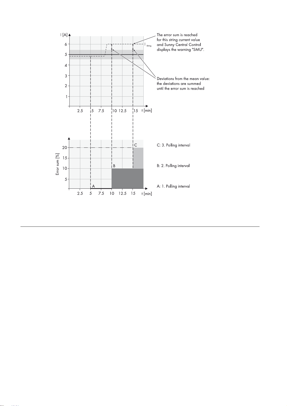
Comparison
Every five minutes, the data logger compares the string current with the mean value for the group. If the string current
exceeds the tolerance limit, the data logger records the deviation. If at the next query, there is still a deviation between
the string current and the mean value, the deviations are added together. If the sum of the deviations exceeds the error
sum, the data logger issues the warning 380 SMU. When the error is acknowledged, the error sum is reset and the
warning disappears from the display.
It is possible to see which Sunny String-Monitor and which measuring channels deviate from the mean value of the group
via the Sunny Central Control or via the SC-COM.
Example:
It is assumed that at time t
range is from 4.5 A to 5.5 A. The tripping time is set to 10 minutes. The query interval is five minutes. The error sum can
therefore be calculated as follows:
the mean value of a group is 5 A. The set tolerance is 10%. This means that the tolerance
0
All string currents are compared with this mean value at the five-minute query interval. If all the string currents are within
the set tolerance of 10%, no addition is carried out.
However, if one string has a string current of 6 A, the difference between the actual string current of 6 A and the tolerance
limit of 5.5 A is added. The difference is 0.5 A which is a deviation of 10% from the mean value. This difference of 10%
is now added to the total until the error sum of 20% is reached.
The error sum is reached when the error remains the same for two query intervals. The data logger issues the warning
380 SMU.
Installation Manual SSMxx-21-IA-BS-JP-en-20 13
Page 14
4 Product Description SMA Solar Technology AG
If a string fails, the current difference in the above example is 4.5 A which equates to a deviation of 90% from the mean
value. Assuming that the settings in the above example remain unaltered, i.e. tolerance at 10% and tripping time at
10 minutes, the error sum of 20% will already be reached after the first query interval of 5 minutes. The data logger
now issues an SMU warning.
4.3 DC Load-Break Switch
The Sunny String-Monitor can be disconnected on the inverter side by means of a DC load-break switch. Use of the DC
load-break switch is only permissible if LV/HRC fuses with gPV characteristic are installed upstream in the inverter or the
main DC distribution box.
14 SSMxx-21-IA-BS-JP-en-20 Installation Manual
Page 15

SMA Solar Technology AG 4 Product Description
4.4 String Fuses
The string fuses protect the PV modules of a PV system from reverse currents. Only install string fuses supplied or approved
by SMA Solar Technology AG as accessories for Sunny String-Monitors.
Figure5: Principle of reverse current
A reverse current can occur when different open-circuit voltages are applied to PV modules connected in parallel. In this
event, the reverse current can be much higher than the short-circuit current of the PV modules. The higher the reverse
current, the more the PV modules of the faulty string will heat up. Strong heat build-up can destroy the modules of the
faulty string.
Reverse current can have the following causes:
• short circuit in one or more modules
• short circuit in one or more cells of a module
• double ground fault in a module
• double ground fault in the cabling
The string fuses trip when the string current is too high and protect the PV modules of the faulty string. The
Sunny String-Monitor informs the inverter of the string failure.
In the case of grounded PV arrays, the positive or the negative terminal can be grounded in the inverter. To do this,
cylindrical bridges are fitted in the Sunny String-Monitor instead of string fuses. Cylindrical bridges are available as
accessories.
4.5 Overvoltage Protection
Depending on the device type, the Sunny String-Monitor is equipped with one or two surge arresters for overvoltage
protection.
In order to guarantee the overvoltage protection function, the surge arrester must be connected to the external grounding.
Components to be protected SSMxx-21-BS SSMxx-21-BS-JP
DC main cable of the Sunny String-Monitor ✓ ✓
RS485 interface and RS485 communication
bus
Installation Manual SSMxx-21-IA-BS-JP-en-20 15
✖✓
Page 16

4 Product Description SMA Solar Technology AG
Components to be protected SSMxx-21-BS SSMxx-21-BS-JP
Voltage supply to the Sunny String-Monitor ✖ ✓
The integrated surge arrester for the DC main cable can be monitored via the Sunny String-Monitor.
4.6 LEDs on the String-Monitor Unit
The LEDs are installed on the String-Monitor Unit. You can determine the status of the communication, voltage supply or
surge arresters via the LEDs.
Figure6: LEDs on the String-Monitor Unit
Designation Name of LED Status Explanation
A DIN1 glowing green The surge arrester is active.
off The surge arrester has tripped.
B RS485 off No data is being exchanged via the
RS485 interface.
glowing yellow Data is being transmitted via the RS485
interface.
C Error off The String-Monitor Unit is functioning
correctly.
glowing red The String-Monitor Unit is defective.
4.7 Type Label
The type label clearly identifies the Sunny String-Monitor. There are two type labels attached to the Sunny String-Monitor.
The type labels are located inside the right-hand door and on the right-hand outside panel of the Sunny String-Monitor.
You will find the following information on the type label:
• Device type and option code
• Serial number
•Production version
• Device-specific characteristics
You will require the information on the type label to use the product safely and when seeking customer support from the
SMA Service Line. The type label must remain permanently attached to the product.
16 SSMxx-21-IA-BS-JP-en-20 Installation Manual
Page 17

SMA Solar Technology AG 4 Product Description
Symbols on the Type Label
Symbol Explanation
Danger to life due to high voltages
The product operates at high voltages. All work on the product must be carried out by qualified
persons only.
Risk of burns due to hot surfaces
The product can get hot during operation. Avoid contact during operation. Allow the product to
cool down sufficiently before carrying out any work. Wear personal protective equipment such as
safety gloves.
Observe the documentation
Observe all documentation supplied with the product.
CE marking
The product complies with the requirements of the applicable EU directives.
WEEE designation
Do not dispose of the product together with the household waste but in accordance with the locally
applicable disposal regulations for electronic waste.
Degree of protection
The product is protected against interior dust deposits and splashing water from all angles.
Installation Manual SSMxx-21-IA-BS-JP-en-20 17
Page 18
5 Mounting SMA Solar Technology AG
:$5 1,1*
&$87,21
5 Mounting
5.1 Wall Mounting
5.1.1 Selecting the Mounting Location
Fire hazard due to wrong choice of mounting location
Under fault conditions electric arcs may occur in the Sunny String-Monitor. Electric arcs can cause fires if the
Sunny String-Monitor is mounted on flammable materials.
• Do not mount the Sunny String-Monitor on flammable construction materials.
• Do not mount the Sunny String-Monitor near highly flammable materials.
• Do not mount the Sunny String-Monitor in potentially explosive atmospheres.
Requirements for the mounting location:
☐ The mounting location must not be in a living or office area.
☐ The mounting location must not block any escape routes.
☐ The mounting location must be freely and safely accessible at all times without the necessity for any auxiliary
equipment (such as scaffolding or lifting platforms). Non-fulfillment of these criteria may restrict servicing.
☐ The mounting location must be suitable for the weight and dimensions of the Sunny String-Monitor (see Section12
"Technical Data", page51).
☐ The mounting location must not be exposed to direct solar irradiation.
Requirements for mounting
• Mount the Sunny String-Monitor so that the connection area is facing downwards.
• Do not mount the Sunny String-Monitor in a horizontal or inclined position.
• An external cable support rail must be provided.
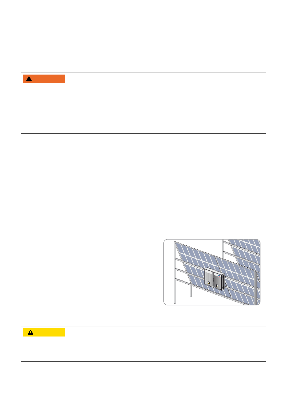
Example: Mounting the Sunny String-Monitor
If the PV array is mounted on a free-standing structure, the
Sunny String-Monitor can be fixed to this structure in a shaded
position. Make sure that the Sunny String-Monitor enclosure is not
mounted in the path of rainwater flowing off the module surface.
5.1.2 Mounting the Sunny String-Monitor
Danger of crushing if the Sunny String-Monitor is dropped
• When mounting the Sunny String-Monitor, take the weight of up to 70 kg into account.
• Two people are needed to mount the Sunny String-Monitor.
18 SSMxx-21-IA-BS-JP-en-20 Installation Manual
Page 19

SMA Solar Technology AG 5 Mounting
/05*$&
Damage to cable glands and plug connections due to improper transport and installation
The cable glands and plug connections protrude from the enclosure.
• Ensure that the cable glands and plug connections are not damaged during mounting and transport.
Additionally required mounting material (not included in the scope of delivery):
• 4 screws M8 Take wall properties into account when choosing the screws.
•4 washers
• If necessary, 4 screw anchors. Choose the screw anchors according to the properties of the wall surface.
Figure7: Dimensions of the Sunny String-Monitor
Procedure:
1. Mark the position of the drill holes on the wall or stand.
2. Drill holes at the marked positions.
3. If necessary, insert the screw anchors.
4. Attach the two mounting rails to the Sunny String-Monitor with the
screws supplied (torque: 15 Nm).
Installation Manual SSMxx-21-IA-BS-JP-en-20 19
Page 20

5 Mounting SMA Solar Technology AG
'$1*(5
/05*$&
5. Fasten the Sunny String-Monitor to the wall or stand using suitable
screws and washers.
6. Ensure that the Sunny String-Monitor is securely in place.
5.2 Base Mounting
The base for the Sunny String-Monitor is available as an accessory.
5.2.1 Selecting the Mounting Location
Danger to life due to fire or explosion
• Do not mount the Sunny String-Monitor on flammable construction materials.
• Do not mount the Sunny String-Monitor near highly flammable materials.
• Do not mount the Sunny String-Monitor in potentially explosive atmospheres.
Requirements for the mounting location:
☐ The mounting location must not be in a living or office area.
☐ The mounting location must not block any escape routes.
☐ The mounting location must be freely and safely accessible at all times without the necessity for any auxiliary
equipment (such as scaffolding or lifting platforms). Non-fulfillment of these criteria may restrict servicing.
☐ The mounting location must be suitable for the weight and dimensions of the Sunny String-Monitor (see Section12
"Technical Data", page51).
☐ The mounting location must not be exposed to direct solar irradiation.
5.2.2 Mounting the Base
Damage to the Sunny String-Monitor due to moisture penetration
Penetrating moisture can lead to condensation, corrosion and creeping currents. The use of a base filler will prevent the
formation of condensation.
• Use a base filler when installing the base.
20 SSMxx-21-IA-BS-JP-en-20 Installation Manual
Page 21

SMA Solar Technology AG 5 Mounting
&$87,21
/05*$&
Figure8: Dimensions of the base foundation
Procedure:
1. Excavate a pit. Make sure to observe the burial depth for the base. Tip: the maximum burial depth is marked on the
sides of the Sunny String-Monitor.
2. Position the base in the excavated pit so that the side with the kick plate faces the front.
3. Remove the upper kick plate.
4. Lay the connection cables in the correct positions in the base.
5. Half-fill the pit with sand or fine gravel.
6. Fill the remaining base area with base filler.
5.2.3 Mounting the Sunny String-Monitor on the Base
Additionally required mounting material (included in the scope of delivery of the accessories):
☐1 base
☐4 nuts
☐ 4 threaded fittings
☐4 fender washers
☐ 2 locking screws for the kick plate
Danger of crushing if the Sunny String-Monitor is dropped
• When mounting the Sunny String-Monitor, take the weight of up to 70 kg into account.
• Two people are needed to mount the Sunny String-Monitor.
Damage to cable glands and plug connections due to improper transport and installation
The cable glands and plug connections protrude from the enclosure.
Procedure:
1. Remove four caps in the base plate of the Sunny String-Monitor.
2. Screw four threaded fittings from underneath into the threaded holes of the base plate.
Installation Manual SSMxx-21-IA-BS-JP-en-20 21
• Ensure that the cable glands and plug connections are not damaged during mounting and transport.
Page 22

5 Mounting SMA Solar Technology AG
3. Place the Sunny String-Monitor on the base.
4. Fasten the Sunny String-Monitor to the base using four fender
washers and four nuts (torque: 10 Nm).
5. Ensure that the Sunny String-Monitor is securely in place.
6. After connecting the cables, fasten the kick plate to the inside of the
base plate using two locking screws.
22 SSMxx-21-IA-BS-JP-en-20 Installation Manual
Page 23

SMA Solar Technology AG 6 Electrical Connection
'$1*(5
6 Electrical Connection
6.1 Safety during Electrical Connection
Danger to life due to electric shock
High voltages are present in the live components of the Sunny String-Monitor. Therefore work on the
Sunny String-Monitor is only allowed if the power is disconnected and the guidelines that apply at the mounting location
are strictly followed.
• Disconnect from voltage sources:
– Switch off the DC load-break switch in the Sunny String-Monitor.
– Remove the DC fuses in the central inverter or main DC distribution box when the power is switched off. Use an
LV/HRC fuse extractor.
– Only open the fuse holders in the Sunny String-Monitor when the power is switched off.
• Ensure that the device cannot be reconnected.
• Ensure that no voltage is present.
• Ground and short-circuit the device.
• Cover or isolate any adjacent live components. Protective covers must always be mounted.
6.2 Inserting the Cables into the Switch Cabinet
Figure9: Bottom view of Sunny String-Monitor with cable glands (example)
Position Designation Explanation
A Condensate drain ‒
B Cable feed-through plate For connecting the string cables
C Cable gland with sealing ring cut-outs For connecting the data cables
D Sealing plug Reserve
E Cable gland with sealing ring cut-outs For connecting the DC main cables
F Cable gland with sealing ring cut-outs For connecting the grounding cable
G Sealing plug Reserve
Leading Cables through the Cable Feed-Through Plate
SMA Solar Technology AG recommends the use of supplementary strain relief for the string cables.
Installation Manual SSMxx-21-IA-BS-JP-en-20 23
Page 24

6 Electrical Connection SMA Solar Technology AG
/05*$&
/05*$&
/05*$&
Damage to the Sunny String-Monitor due to moisture penetration
Moisture can penetrate the Sunny String-Monitor through redundant holes in the membranes of the cable feed-through
plate.
• Only pierce as many holes in the membrane as you need for the cables.
Procedure:
1. Pierce the appropriate membranes.
2. Insert the string cables through the membranes.
3. Cut the string cables to length.
Leading the Cables through the Cable Glands with Sealing Ring Cut-Outs
Damage to the Sunny String-Monitor due to moisture penetration
Moisture can penetrate the Sunny String-Monitor through unsealed cable glands.
• Only remove the required number of sealing rings from the sealing plugs of the cable glands to match the cable
diameter.
Damage to the cable gland for DC main cables due to incorrectly inserted cables
The DC main cables must be inserted straight through the cable gland. Any transverse stress on the cable gland due to
skewed insertion of cables can damage the cable gland and the base plate of the Sunny String-Monitor.
• Ensure that the DC main cables are led straight through the cable gland.
Lead each cable through the cable glands as described below.
Procedure:
1. Remove the sealing plug from the cable gland.
2. Adjust the sealing plug to the diameter of the cable to be inserted. To do this, cut out the required number of sealing
rings from the center of the sealing plug.
3. Lead the cable through the swivel nut of the cable gland. Ensure that the thread of the swivel nut is facing upwards.
4. Lead the cable through the sealing plug.
5. Insert the sealing plug with the cable into the cable gland.
6. Cut the cable to length.
7. Firmly tighten the cable gland (torque: 5 Nm).
24 SSMxx-21-IA-BS-JP-en-20 Installation Manual
Page 25

SMA Solar Technology AG 6 Electrical Connection
6.3 Overview of the Connection Area
6.3.1 SSM8-21-BS/SSM16-21-BS
The features of the Sunny String-Monitor are dependent on the order option. The maximum configuration of the
Sunny String-Monitor is shown in the overview diagrams.
Figure10: Connections (with SSM16-21-BS as an example)
Position Designation
A Terminals for string cables, positive terminal
B Terminal for data cables
CTerminal for DC main cable, positive terminal
D Terminal for grounding cable
ETerminal for DC main cable, negative terminal
F Terminals for string cables, negative terminal
Installation Manual SSMxx-21-IA-BS-JP-en-20 25
Page 26

6 Electrical Connection SMA Solar Technology AG
6.3.2 SSM8-21-BS-JP/SSM16-21-BS-JP
The features of the Sunny String-Monitor are dependent on the order option. The maximum configuration of the
Sunny String-Monitor is shown in the overview diagrams.
Figure11: Connections (with the SSM16-21-BS-JP as an example)
Position Designation
A Terminals for string cables, positive terminal
B Terminal for data cables
C Terminal for DC main cable, positive terminal
D Grounding cable connection
E Terminal for DC main cable, negative terminal
F Terminals for string cables, negative terminal
6.4 Connecting the String Cables
SMA Solar Technology AG recommends using bootlace ferrules for connecting the string cables to the fuse holders.
Cable requirements:
☐ PV1-F cable must be available.
☐ Conductor cross-section of the string cable for connection of one string cable to the fuse holders: 0.75 mm
16 mm
2
2
to
26 SSMxx-21-IA-BS-JP-en-20 Installation Manual
Page 27

SMA Solar Technology AG 6 Electrical Connection
/05*$&
Procedure:
1. Attach the string cables to a cable support rail.
2. Cut the string cables to length and strip off the insulation by 11 mm.
3. If you are using bootlace ferrules, mount the bootlace ferrules and crimp gas-tight.
4. Connect the string cables to the screw terminals of the fuse holders (torque: 2.5 Nm). Ensure correct polarity.
6.5 Connecting the DC Main Cables
6.5.1 Cable Requirements
The Sunny String-Monitor comes supplied with busbars for connecting the DC cables with terminal lugs. If you wish to
connect the DC cables directly to the terminals, the appropriate terminals are available as accessories.
Failure of data transmission due to incorrect cable installation
Non-compliance with the minimum clearances between the DC main cables and the data cable may lead to failure of
data transmission. This can result in yield loss.
• When laying the DC main cables, ensure that the minimum clearance of 400 mm to the data cables is observed.
Requirements for DC main cables and terminal lugs:
☐ Use copper or aluminum cables only.
☐ Use only tin-plated copper ring terminal lugs for copper cables or bimetal ring terminal lugs for aluminum cables.
☐ The width of the terminal lug contact surface must exceed the diameter of the washers (32 mm).
Requirements for DC main cables for connection to terminals available as accessories:
☐ Use copper or aluminum cables only.
☐ The conductor cross-sections of the DC main cables must be selected correctly:
Conductor type Conductor cross-section
2
Round, single-strand 25 mm
to 150 mm
Round, multi-strand 25 mm2 to 300 mm
Sectoral, single-strand 25 mm2 to 240 mm
Sectoral, multi-strand 25 mm2 to 240 mm
2
2
2
2
Installation Manual SSMxx-21-IA-BS-JP-en-20 27
Page 28

6 Electrical Connection SMA Solar Technology AG
6.5.2 Connecting DC Main Cables to the Busbar
Figure12: Assembly of the connection with a ring terminal lug
Position Designation
AScrew M12
BSpring washer
C Fender washer
D Tin-plated copper bar
E Tin-plated ring terminal lug
FNut M12
Additionally required material (not included in the scope of delivery):
☐ Ring terminal lugs (size: for M12 screw)
☐Clean cloth
☐ Ethanol cleaning agent
Procedure:
1. Strip off the DC main cable insulation.
2. Fit the DC main cables with ring terminal lugs.
3. Clean the contact surfaces using a clean cloth and ethanol cleaning agent. Do not touch the contact surfaces after
cleaning.
4. Connect the DC main cables in accordance with the circuit diagram (torque: 60 Nm). Only use the supplied
fastening material and connect a maximum of two adjacent DC main cables to each busbar.
5. Secure the DC main cables to the cable support rail.
28 SSMxx-21-IA-BS-JP-en-20 Installation Manual
Page 29

SMA Solar Technology AG 6 Electrical Connection
6.5.3 Connecting DC Main Cables to the Terminals
The terminals are available as accessories.
Mounting Terminals to the Busbar
Figure13: Connection of terminals to busbars
Position Designation
AScrew M12
BSpring washer
CFender washer
D Tin-plated copper bar
ETerminal
FNut M12
Additionally required material:
☐ Ethanol cleaning agent
☐Clean cloth
Procedure:
1. Wipe the contact surfaces on the busbar and the terminal with a clean cloth and ethanol cleaner. Do not touch the
surfaces once they have been cleaned.
2. Mount the terminals on the busbar (torque: 60 Nm). Only use the supplied screws, nuts and washers and make sure
that the screw heads always point backwards.
Connecting Copper Cables to the Terminals
1. Strip off the DC main cable insulations by 35 mm.
2. Connect the DC main cables to the terminals:
• Unscrew the set screw with an Allen key.
• Insert the DC main cables into the terminal from below. Ensure correct polarity.
• Fasten the set screw (torque: 32 Nm).
3. Ensure that the DC main cables are securely in place.
Installation Manual SSMxx-21-IA-BS-JP-en-20 29
Page 30

6 Electrical Connection SMA Solar Technology AG
:$5 1,1*
:$5 1,1*
Connecting Aluminum Cables to the Terminals
Upon contact with oxygen, an oxide film forms on aluminum surfaces. This oxide film increases transition resistances. For
this reason, the insulated conductors of the aluminum cables must be cleaned immediately before connecting them. If they
are not to be connected immediately after cleaning, the cable ends need to be greased. SMA Solar Technology AG
recommends connecting the greased insulated conductors to the terminals within eight hours.
Risk of fire if dirty or oxidized aluminum cables are connected
Connecting dirty or oxidized DC main cables reduces the ampacity of the live terminals, thereby increasing the transition
resistances. This can cause components to overheat and catch fire.
• Only connect clean and oxide-free conductors of the aluminum cable.
• Ensure that the conductors are free of iron particles.
• Connect the insulated conductors to the terminals within ten minutes after cleaning.
Procedure:
1. Strip off the DC main cable insulations by 35 mm.
2. Remove any oxide film from the insulated conductors, e.g. with a sharp knife. Do not use a file, sandpaper or brush.
3. Ensure that no further contamination occurs on the insulated conductors.
4. If you do not connect the insulated conductors within ten minutes after cleaning, grease the insulated conductors.
This prevents the formation of an oxide film.
5. Unscrew the set screw with an Allen key.
6.
Risk of fire from contact failure if grease comes into contact with the set screw
Grease on the set screw can result in failure to achieve the prescribed torque. Contact failure and increased
transition resistances are the result.
• Insert the insulated conductors into the terminal from below. Ensure that no grease comes into contact with the
set screw.
7. Fasten the set screw (torque: 32 Nm).
8. Ensure that the DC main cables are securely in place.
6.6 Connecting the Grounding Cable
6.6.1 Connecting the Grounding Cable in the SSMxx21-BS
In order to guarantee the function of the surge arrester, it must be connected to the external grounding.
Cable requirement:
☐ Conductor cross-section: 16 mm
Requirement:
The grounding cable must be routed into the Sunny String-Monitor through the cable gland (see Section6.2, page23).
2
to 25 mm
2
Procedure:
1. Strip off the grounding cable insulation by 16 mm.
2. Connect the grounding cable to the screw terminal of the surge arrester (torque: 2.5 Nm).
3. Ensure that the grounding cable is securely in place.
4. Ground the grounding cable in the vicinity of the Sunny String-Monitor, e.g. by means of a grounding electrode.
30 SSMxx-21-IA-BS-JP-en-20 Installation Manual
Page 31

SMA Solar Technology AG 6 Electrical Connection
6.6.2 Connecting the Grounding Cable in the SSMxx21-BS-JP
In the device type SSMxx-21-BS-JP, an additional surge arrester is installed for the RS485 communication. To guarantee
the functionality of the surge arresters, they must be connected to the external grounding.
Cable requirement:
2
☐ Conductor cross-section: 16 mm
Requirement:
☐ The grounding cable must be routed into the Sunny String-Monitor through the cable gland (see Section6.2,
page23).
Procedure:
1. Strip off the grounding cable insulation by 16 mm.
2. Connect the grounding cable to the screw terminal -X100 (torque: 3.2 Nm).
3. Ensure that the grounding cable is securely in place.
4. Tighten the grounding cable gland.
5. Ground the grounding cable in the vicinity of the Sunny String-Monitor, e.g. by means of a grounding electrode.
to 35 mm
2
6.7 Connecting the Data Cables
6.7.1 Cable Requirements
Requirement:
☐ The voltage supply and the communication connection must be combined in one cable.
For an optimum voltage supply, SMA Solar Technology AG recommends connecting two insulated conductors with a
cross section of 0.5 mm
for the GND_EXT signal in just the same way.
Recommended cable type: Li2YCYv (TP) 4 x 2 x 0.5 mm
6.7.2 Connecting the Data Cables in the SSMxx-21-BS
The Sunny String-Monitors must be connected to the RS485 communication bus. This means that two data cables will be
connected to each Sunny String-Monitor. Only one data cable is connected and terminated in the last
Sunny String-Monitor.
2
each to one voltage supply terminal. You can connect two insulated conductors to one terminal
2
.
Figure14: Connection of Sunny String-Monitors to the RS485 communication bus (example)
Installation Manual SSMxx-21-IA-BS-JP-en-20 31
Page 32

6 Electrical Connection SMA Solar Technology AG
Limited number of String-Monitor Units per Ethernet hub
Since the String-Monitor Unit measurement PCBs are supplied with voltage via the data cables, the number of
connected String-Monitor Units is limited.
• Do not connect more than ten String-Monitor Units per Ethernet hub.
The various types of Sunny String-Monitors are equipped with differing numbers of String-Monitor Units:
• Sunny String-Monitor SSM8-21: 1 String-Monitor Unit
• Sunny String-Monitor SSM16-21: 2 String-Monitor Units
The data cables are connected to the lowest String-Monitor Unit measurement PCB via a connector.
Procedure:
To connect the data cables in the Sunny String-Monitor, carry out the following steps in the given sequence. The exact
procedure is described in the following sections.
• Preparing the data cables
• Connecting the data cables to the connectors
• Connecting the connector to the String-Monitor Unit
Preparing the Data Cables
Requirement:
☐ The data cables must be routed into the Sunny String-Monitor through the cable glands (see Section6.2 "Inserting
the Cables into the Switch Cabinet", page23)
Additionally required material (not included in the scope of delivery):
☐ 1 bootlace ferrule for conductor cross-section 6 mm
2
Procedure:
1. Dismantle the data cables by 100 mm.
2. Unravel the cable shield of the data cables.
3. Push the unraveled cable shield to one side of each data cable and twist.
4. If you are connecting two data cables, twist the cable shields of the data cables together.
5. Shorten the twisted cable shield to 20 mm.
6. Mount the bootlace ferrule on the twisted cable shield and crimp.
Connecting the Data Cables to the Connectors
Additionally required material (not included in the scope of delivery):
☐ 3 cable ties (dimensions: 100 mm x 2.5 mm)
Procedure:
1. Strip off the insulated conductors of the data cables by 10 mm.
2. Remove the connector of the lowest String-Monitor Unit.
3. Connect the insulated conductors of the data cables to the female connector in accordance with the circuit diagram:
• Hold the actuation lever down.
• Insert the insulated conductor:
Terminal Signal Color of insulated conductor*
Pin 1 GND_EXT Conductor pair: white/brown
Pin 2 RS485L green
32 SSMxx-21-IA-BS-JP-en-20 Installation Manual
Page 33

SMA Solar Technology AG 6 Electrical Connection
Terminal Signal Color of insulated conductor*
Pin 3 RS485H yellow
Pin 4 +60V_EXT Conductor pair: gray/pink
Pin 5 GND_EXT Conductor pair: white/brown
Pin 6 RS485L green
Pin 7 RS485H yellow
Pin 8 +60V_EXT Conductor pair: gray/pink
* as per DIN EN 47100; the color of the insulated conductor can vary depending on the cable
• Let go of the actuation lever.
• Ensure that the insulated conductors are firmly in place.
4. Bundle the insulated conductors of the data cables with a cable tie.
5. Position the bootlace ferrule between the data cables and the
connector.
6. Attach the data cables to the connector using two cable ties.
Installation Manual SSMxx-21-IA-BS-JP-en-20 33
Page 34

6 Electrical Connection SMA Solar Technology AG
Connecting the Connector to the String-Monitor Unit
• Plug the connector with the connected data cables into the pin
connector of the lowest String-Monitor Unit.
6.7.3 Connecting the Data Cable in the SSMxx-21-BS-JP
The Sunny String-Monitors must be connected to the RS485 communication bus and supplied with voltage.
The RS485 data cables and the voltage supply are connected jointly in one data cable to terminals -X712 and -X713
by means of a connector. This means that two data cables will be connected to each Sunny String-Monitor. Only one
data cable is connected and terminated at the last Sunny String-Monitor.
Figure15: Connection of Sunny String-Monitors to the RS485 communication bus (example)
Limited number of String-Monitor Units per Ethernet hub
Since the String-Monitor Unit measurement PCBs are supplied with voltage via the data cables, the number of
connected String-Monitor Units is limited.
• Do not connect more than ten String-Monitor Units per Ethernet hub.
The various types of Sunny String-Monitors are equipped with differing numbers of String-Monitor Units:
• Sunny String-Monitor SSM8-21: 1 String-Monitor Unit
• Sunny String-Monitor SSM16-21: 2 String-Monitor Units
• Sunny String-Monitor SSM24-21: 3 String-Monitor Units
Procedure:
To connect the data cables in the Sunny String-Monitor, carry out the following steps in the given sequence. The exact
procedure is described in the following sections.
• Preparing the data cables
• Connecting the data cables to the connectors
• Connecting the connectors in the Sunny String-Monitor
34 SSMxx-21-IA-BS-JP-en-20 Installation Manual
Page 35

SMA Solar Technology AG 6 Electrical Connection
Preparing the Data Cables
Requirement:
☐ The data cables must be routed into the Sunny String-Monitor through cable glands (see Section6.2, page23).
Additionally required mounting material (not included in the scope of delivery):
☐ Conductive adhesive foil
Procedure:
1. Dismantle the data cables by 100 mm.
2. Fold the surplus cable shield of the data cables back over the
cable sheath.
3. Wrap the cable shield in conductive adhesive foil.
Connecting the Data Cables to the Connectors
Pin assignment in the connector
Voltage supply to the Sunny String-Monitors
To minimize voltage drops between the separate Sunny String-Monitors, one insulated conductor pair must be
assigned to each of the pins for voltage supply.
Pin Assignment
1GND_EXT
2 RS485L
3 RS485H
4 +60V_EXT
Procedure:
1. Strip off the insulated conductors of the data cables by 10 mm.
2. Remove the connectors from the customer terminals -X712 and -X713.
Installation Manual SSMxx-21-IA-BS-JP-en-20 35
Page 36

6 Electrical Connection SMA Solar Technology AG
3. Connect the conductors of the data cables to the female connector of the connectors in accordance with the circuit
diagram. The conductors for the voltage supply must be drilled pairs.
• Hold the actuation lever down.
• Insert the insulated conductor.
• Let go of the actuation lever.
• Ensure that the insulated conductors are firmly in place.
4. Shorten all other conductors flush with the cable sheath.
5. Clamp the data cables into the respective shield clamp.
6. Fasten the data cable glands.
36 SSMxx-21-IA-BS-JP-en-20 Installation Manual
Page 37

SMA Solar Technology AG 6 Electrical Connection
Connecting the Connectors in the Sunny String-Monitor
• Insert the connectors with the connected data cables into the pin
connectors of the terminals -X712 and -X713.
6.7.4 Connecting the Data Cables in the Sunny Central
In the inverter, the data cables are connected to a separate connecting terminal plate. There are three communication
terminals, to each of which up to ten String-Monitor Units can be connected (for information on how to connect
Sunny String-Monitors to Sunny Central inverters of the CP production series, see the installation manual of the respective
central inverter.)
Installation Manual SSMxx-21-IA-BS-JP-en-20 37
Page 38

7 Commissioning SMA Solar Technology AG
'$1*(5
7 Commissioning
7.1 Safety during Commissioning
Danger to life from electric shock due to live voltage
High voltages are present in the live components of the Sunny String-Monitor. Touching live components results in death
or serious injury due to electric shock.
• Wear personal protective equipment when working on the Sunny String-Monitor.
• Do not touch live components.
• Before performing any work, always disconnect the Sunny String-Monitor from voltage sources unless supply
voltage is absolutely necessary.
– Switch off the DC load-break switch in the Sunny String-Monitor.
– Remove the DC fuses in the central inverter or main DC distribution box when the power is switched off. Use the
LV/HRC fuse handle.
– Only open the fuse holders in the Sunny String-Monitor when the power is switched off.
• Ensure that the device cannot be reconnected.
• Ensure that no voltage is present.
• Ground and short-circuit the device.
• Cover or isolate any adjacent live components. Protective covers must always be mounted.
7.2 Commissioning the Sunny String-Monitor
7.2.1 Requirements for Commissioning
Commissioning is to be performed by Service employees only
Commissioning of the Sunny String-Monitor must be performed by Service employees of SMA Solar Technology AG
or their authorized representatives only.
The commissioning report must be completed during commissioning.
Requirements:
☐ The DC load-break switch must be switched off.
☐ The DC main cables must be connected to the inverter or main DC distribution box and disconnected from voltage
sources.
☐ There is no reverse voltage from the inverter.
☐ All connections must be made in accordance with this manual (see Section6 "Electrical Connection", page23).
☐ The correct polarity of all connections must be ensured and documented.
☐ The floor around the Sunny String-Monitors must be firm and freely accessible.
7.2.2 Terminating the Data Cable
The last Sunny String-Monitor of each string and the Ethernet hubs in the Sunny Central must be terminated.
The Sunny String-Monitors are not terminated upon delivery so that they can be configured as required on site. The
Ethernet hubs in the Sunny Central are terminated upon delivery.
38 SSMxx-21-IA-BS-JP-en-20 Installation Manual
Page 39

SMA Solar Technology AG 7 Commissioning
Figure16: Termination of the Sunny String-Monitors (example)
Requirement:
☐ All Sunny String-Monitors in a string are connected to the RS485 communication bus (see Section6.7 "Connecting
the Data Cables", page31).
Procedure:
1. In the last Sunny String-Monitor of each string, plug the jumper into
pin header S1 at position T on the lowest String-Monitor Unit.
2. Make sure that in the other Sunny String-Monitors of the string, the
jumpers are plugged into pin header S1 at position P of the lowest String-Monitor Unit.
Installation Manual SSMxx-21-IA-BS-JP-en-20 39
Page 40

7 Commissioning SMA Solar Technology AG
:$5 1,1*
'$1*(5
7.2.3 Noting Down the Serial Number of the String-Monitor Unit
The serial number clearly identifies the String-Monitor Unit. The serial number can be found on the type label at the bottom
right-hand corner of the String-Monitor Unit.
You will need the serial numbers for detecting the String-Monitor Units. All serial numbers of the String-Monitor Units must
be noted in the commissioning report.
Figure17: Position of the serial number on the String-Monitor Unit
Position Designation
A Serial number of the String-Monitor Unit
Procedure:
• Identify the serial numbers of the String-Monitor Units and note them in the commissioning report.
7.3 Switching On the Sunny String-Monitor
Fire risk caused by incorrect rating of string fuses or by use of incorrect string fuses
• Ensure that the rating of the string fuses is correct.
• Only install string fuses supplied or approved by SMA Solar Technology AG for Sunny String-Monitors.
Requirement:
☐ The String-Monitor Unit is supplied with voltage.
Procedure:
1. Open the fuse holders.
2.
Danger to life due to electric shock if live components of the Sunny String-Monitor are touched
• Only insert the string fuses in the Sunny String-Monitor when the power is switched off.
3. Close the fuse holders.
4. Switch on the DC load-break switch.
40 SSMxx-21-IA-BS-JP-en-20 Installation Manual
Page 41

SMA Solar Technology AG 8 Disconnecting the Sunny String-Monitor
'$1*(5
:$5 1,1*
:$5 1,1*
:$5 1,1*
8 Disconnecting the Sunny String-Monitor
Danger to life due to electric shock if live components of the Sunny String-Monitor are touched
• Observe the following safety rules when disconnecting:
– Disconnect the device from voltage sources.
– Ensure that the device cannot be reconnected.
– Ensure that no voltage or current is present.
– Ground and short-circuit the device.
– Cover or isolate any adjacent live components.
Risk of burns from touching hot components
• Wear personal safety equipment when working on the device.
Danger to life from electric shock if the DC load-break switch is damaged
Switching the DC load-break switch at temperatures below ‒25°C may cause damage to the DC load-break switch.
Correct disconnection function can no longer be guaranteed. High voltages are present in components that are not
properly disconnected. Touching live components can result in death or serious injury due to electric shock.
•Do not switch the DC load-break switch at temperatures below ‒25°C.
Danger to life from electric shock due to damaged fuse holders
Using the fuse holders at temperatures below ‒25°C may cause damage to the fuse holders. Correct disconnection
function can no longer be guaranteed. High voltages are present in components that are not properly disconnected.
Touching live components can result in death or serious injury due to electric shock.
• Do not use the fuse holders at temperatures below ‒25°C.
Procedure:
1. Switch off the DC load-break switch. This ensures that there is no current flow through the Sunny String-Monitor.
2. Disconnect the Sunny Central from voltage sources (see Sunny Central installation manual).
If there are fuses in the Sunny Central, remove them. Use the LV/HRC fuse handle.
or
If there are no fuses in the Sunny Central, remove the fuses in the DC main distributor.
3. Only open the fuse holders in the Sunny String-Monitor when the power is switched off.
Installation Manual SSMxx-21-IA-BS-JP-en-20 41
Page 42

9 Troubleshooting SMA Solar Technology AG
9 Troubleshooting
Symptom Cause and corrective measures
LED DIN1 is off. The surge arrester for the DC main cable has tripped.
Corrective measures:
• If the Sunny String-Monitor is equipped with a modular surge arrester, replace the
defective module in the surge arrester.
• Ensure that the surge arrester for overvoltage protection is functioning.
The LED Error is glowing. The String-Monitor Unit is defective.
Corrective measures:
• Contact the SMA Service Line.
The LED RS485 has been
off for more than five
minutes.
The data cable is damaged or not properly connected and terminated.
Corrective measures:
• Ensure that the data cable is connected correctly (see Section6.7 "Connecting the
Data Cables", page31).
• Ensure that the cabling between the Sunny Central and the Sunny String-Monitors is
OK.
• Ensure that the data cable in the last Sunny String-Monitor of a string is terminated (see
Section7.2.2 "Terminating the Data Cable", page38).
The serial interface is not correctly configured.
Corrective measures:
• Configure the serial interface correctly (see user manual of the inverter).
42 SSMxx-21-IA-BS-JP-en-20 Installation Manual
Page 43

SMA Solar Technology AG 10 Maintenance
10 Maintenance
10.1 Maintenance Interval
• Maintenance is to be performed on the Sunny String-Monitor every 24 months.
10.2 Overview of the Main Components
Figure18: Main components of the Sunny String-Monitor (with SSM16-21-BS-JP as an example)
Installation Manual SSMxx-21-IA-BS-JP-en-20 43
Page 44

10 Maintenance SMA Solar Technology AG
Figure19: Main components of the Sunny String-Monitor (with SSM16-21-BS as an example)
Position Designation
A Terminals for string cables, positive terminal
B Terminal for data cables
C Terminal for DC main cable, positive terminal
D Terminal for grounding cable
E Terminal for DC main cable, negative terminal
F Terminals for string cables, negative terminal
G Condensate drain
H Cable feed-through plate
I Cable gland with sealing ring cut-outs
44 SSMxx-21-IA-BS-JP-en-20 Installation Manual
Page 45

SMA Solar Technology AG 10 Maintenance
'$1*(5
'$1*(5
Position Designation
K Sealing plug
L Cable gland with sealing ring cut-outs
M Cable gland with sealing ring cut-outs
N Sealing plug
10.3 Checking the Mounting Location and the Installation
• Remove all inflammable materials.
• Ensure that the Sunny String-Monitor is securely in place.
• Ensure that the Sunny String-Monitor is not exposed to direct solar irradiation.
• Ensure that the mounting location is accessible at all times.
10.4 Checking the Enclosure
• Check whether the enclosure is damaged.
If the enclosure is badly damaged or cracked, it must be replaced.
• Check whether the seals are damaged.
If the seals are damaged, replace them.
• Ensure that the vent plugs in the enclosure are intact and clean.
• Ensure that the lock is intact and functional.
10.5 Checking the Inside of the Enclosure
1.
Danger to life by electric shock or electric arc if live components are touched
• Disconnect the Sunny String-Monitor from voltage sources (see Section8, page41).
2. Ensure tightness of the Sunny String-Monitor.
3. Ensure that the drain plugs are intact and clean.
4. Ensure that there is no condensation water inside the enclosure.
10.6 Checking the Base Plate
1.
Danger to life by electric shock or electric arc if live components are touched
• Disconnect the Sunny String-Monitor from voltage sources (see Section8, page41).
2. Ensure that all cable glands are sealed and securely in place.
3. Ensure that the DC connectors are intact and securely in place.
Installation Manual SSMxx-21-IA-BS-JP-en-20 45
Page 46

10 Maintenance SMA Solar Technology AG
10.7 Checking the Covers and Labels
Figure20: Position of the labels in and on the Sunny String-Monitor (with the SSM 21-BS as an example)
Position SMA order number Designation
A 86- 101700.02* Risk of electric shock. Do not actuate the load-break switch at temperatures below
-25°C.
B 86-051488 Warning regarding dangerous voltage
C 86-0514 Negative terminal (L − )
D 86-101700.02* Two labels:
Risk of electric shock from active power source
and
Damage to the system due to incorrectly rated fuses Maximum output current:
200 A
or
Risk of electric shock from active power source
and
Damage to the system due to incorrectly rated fuses Maximum output current:
280 A
46 SSMxx-21-IA-BS-JP-en-20 Installation Manual
Page 47

SMA Solar Technology AG 10 Maintenance
'$1*(5
'$1*(5
'$1*(5
'$1*(5
Position SMA order number Designation
E 86-0512 Positive terminal (L+)
F 86-101700.02* Three labels:
Risk of electric shock from active power source
Risk of electric arc
Risk of burns due to hot components
* Material number of the label sheet with all warning labels for all product versions
Procedure:
1.
Danger to life by electric shock or electric arc if live components are touched
• Disconnect the Sunny String-Monitor from voltage sources (see Section8, page41).
2. Check whether the warning labels on and inside the device are damaged or missing.
Replace warning labels if damaged or missing. Select a warning label that is correct for the product version.
3. Check that the cover latches are undamaged and securely in place.
If the cover latches are damaged or loose, they must be replaced.
10.8 Checking the Fuse Holders
1.
Danger to life due to electric arcs when opening the fuse holders
• Only open the fuse holders in the Sunny String-Monitor when the power is switched off.
2. Check the fuse holders for discoloration or changed appearance.
If they are discolored or changed in any way, contact the SMA Service Line.
3. Ensure that each fuse holder opens and closes properly.
10.9 Checking the Bolted, Clamp and Plug Connections
1.
Danger to life by electric shock or electric arc if live components are touched
• Disconnect the Sunny String-Monitor from voltage sources (see Section8, page41).
2. Ensure that the bolted connections of the power cables are securely in place.
3. Check whether there is any discoloration or change in appearance of the bolted connections at the insulation or the
terminals.
If the bolted connections and terminals show discoloration or a changed appearance, replace them.
4. Ensure that all connectors are intact and securely in place.
10.10 Checking the Surge Arrester for the DC Main Cable
1.
2. Check whether the ready indicator on the surge arrester is red.
Installation Manual SSMxx-21-IA-BS-JP-en-20 47
Danger to life by electric shock or electric arc if live components are touched
• Disconnect the Sunny String-Monitor from voltage sources (see Section8, page41).
If the ready indicator is red, replace the protection module.
Page 48

10 Maintenance SMA Solar Technology AG
'$1*(5
'$1*(5
10.11 Checking the Surge Arrester for RS485 Communication
In device type SSMxx-21-BS-JP, there is a surge arrester for RS485 communication installed.
Additionally required material (not included in the scope of delivery):
☐ Measuring device DEHNrecorder LC M3
☐ Measuring device PM20
☐ Test adapter PA BXT
Procedure:
1.
Danger to life by electric shock or electric arc if live components are touched
• Disconnect the Sunny String-Monitor from voltage sources (see Section8, page41).
2. For the surge arrester BVT ALD 60, use the measuring device PM20 3 to perform the measurements (see
documentation of the measuring device). Check whether the readings are within the tolerance range defined by the
lower threshold LLV and the upper threshold ULV:
Measurement 1 Measurement 2Measurement 3
LLV 0 V 73 V 0 V
ULV 219 V 83 V 1 V
If the readings are outside the tolerance limits, replace the surge arrester.
3. For the module BXT ML2 BD, use the measuring device PM20 3 to perform the measurements (see documentation
of the measuring device). Check whether the readings are within the tolerance range defined by the lower threshold
LLV and the upper threshold ULV:
Measurement 1 Measurement 2Measurement 3
LLV 182 V 17 V 0 V
ULV 279 V 22 V 1 V
If the readings are outside the tolerance limits, replace the surge arrester.
10.12 Checking the Supply Voltage
Required maintenance material (not included in the scope of delivery):
☐ Voltmeter
Requirement:
☐ The circuit breaker for the supply voltage of the Sunny Central must be switched on.
Procedure:
1.
Danger to life by electric shock or electric arc if live components are touched
• Disconnect the Sunny String-Monitor from voltage sources (see Section8, page41).
2. Measure the supply voltage at the connector on the lowest String-Monitor Unit.
☑ The supply voltage is at least 30 V.
✖ The supply voltage is less than 30 V?
48 SSMxx-21-IA-BS-JP-en-20 Installation Manual
Page 49

SMA Solar Technology AG 10 Maintenance
'$1*(5
'$1*(5
• Check the terminals. Attach the cable, if necessary.
10.13 Checking the Ground Connection
1.
Danger to life by electric shock or electric arc if live components are touched
• Disconnect the Sunny String-Monitor from voltage sources (see Section8, page41).
2. Ensure that the ground connection and the contact resistance to the ground potential are correct.
10.14 Checking the LEDs of the String-Monitor Unit
Figure21: LED Error on the String-Monitor Unit
Position Designation
ALED Error
Procedure:
1.
Danger to life by electric shock or electric arc if live components are touched
• Disconnect the Sunny String-Monitor from voltage sources (see Section8, page41).
2. If the red Error LED on the String-Monitor Unit is glowing, contact the SMA Service Line.
Installation Manual SSMxx-21-IA-BS-JP-en-20 49
Page 50

11 Decommissioning SMA Solar Technology AG
11 Decommissioning
11.1 Disassembling the Sunny String-Monitor
Requirement:
☐ The Sunny String-Monitor is disconnected from voltage sources (see Section8 "Disconnecting the
Sunny String-Monitor", page41).
Procedure:
1. Open the doors of the Sunny String-Monitor.
2. Disconnect the string cables from the fuse holders.
3. Disconnect the DC main cable.
4. Disconnect the grounding cable.
5. Release the cable glands.
6. Pull all cables out of cable glands and cable feed-through plates.
7. Disassemble the Sunny String-Monitor.
11.2 Disposing of the Sunny String-Monitor
• Dispose of the Sunny String-Monitor in accordance with the applicable disposal regulations for electronic waste.
50 SSMxx-21-IA-BS-JP-en-20 Installation Manual
Page 51

SMA Solar Technology AG 12 Technical Data
12 Technical Data
Enclosure
Outdoor installation Shaded
Material Glass-fiber reinforced plastic
Combustion properties Self-extinguishing, halogen-free
Color RAL7035
UV resistance Yes
Wall mounting Yes
Base mounting*
Yes
Protective insulation Yes
Lock cylinder**
Double-bit key for switch cabinet
Cylinder length 30/10 or 35/10
Cable support rail***
* base available as accessory
** prepared for customer mounting of a profile half-cylinder
*** only for base mounting
Yes
Mechanical Data of Wall-Mounted Device
Width of enclosure 1,058 mm
Width of enclosure including pressure equalization plug 1,088 mm
Height of enclosure 848 mm
Height of enclosure including cable glands 898 mm
Depth of enclosure 245 mm
Depth of enclosure including lock 273 mm
Maximum weight without base 70 kg
Mechanical Data of Base-Mounted Device*
Width of enclosure 1,058 mm
Width of enclosure including pressure equalization plug 1,088 mm
Height of enclosure 848 mm
Height of base 883 mm
Total height 1,731 mm
Depth of enclosure 245 mm
Depth of enclosure including lock 273 mm
Weight of base 16 kg
Maximum weight with base 86 kg
Burial depth of base 595 mm
* base available as accessory
Installation Manual SSMxx-21-IA-BS-JP-en-20 51
Page 52

12 Technical Data SMA Solar Technology AG
Electrical Data
PV array Negatively grounded/positively grounded/isolated
Maximum DC input voltage 1,000 V
Maximum DC output current for SSM8-21-BS/SSM8-21-BS-JP 200 A
Maximum DC output current for SSM16-21-BS/
280 A
DC
DC
DC
SSM16-21-BS-JP
Maximum reverse current 15 kA
DC
Fuse characteristics gPV
Nominal current strength of string fuses 6 A
/8 ADC/10 ADC/12 ADC/15 ADC/20 ADC/
DC
25 A
DC
/30 A
Dimensions of string fuses 10 x 38 mm
Maximum current per fuse at maximum current of 25 A
measuring channel, maximum output current of 200 A
280 A
and ambient temperature of 40°C
DC
Maximum current per fuse at maximum current of 25 ADC per
measuring channel, maximum output current of 200 A
280 A
and ambient temperature of 50°C
DC
Maximum current per measuring input 25 A
Number of string inputs per potential SSM8-21-BS/
DC
DC
DC
per
/
/
0.60 x I
0.55 x I
16
nom fuse
nom fuse
DC
SSM8-21-BS-JP
DC
Number of string inputs per potential SSM16-21-BS/
32
SSM16-21-BS-JP
Number of string fuses per potential SSM8-21-BS/
16
SSM8-21-BS-JP
Number of string fuses per potential SSM16-21-BS/
32
SSM16-21-BS-JP
Number of measuring inputs per potential SSM8-21-BS/
8
SSM8-21-BS-JP
Number of measuring inputs per potential SSM16-21-BS/
16
SSM16-21-BS-JP
External DC supply voltage*
35 VDC to 55 V
DC load-break switch 280 A
Surge arrester for DC input Type 2
Surge arrester for RS485 communication SSM8-21-BS-JP/
Type 2
SSM16-21-BS-JP
Overvoltage category II
* via the data cable for RS 485 communication
DC Main Connection to Busbar
DC
DC
Connection to busbar Ring terminal lugs for M12 screw
Maximum conductor cross-section 300 mm
2
Cable gland M40
52 SSMxx-21-IA-BS-JP-en-20 Installation Manual
Page 53

SMA Solar Technology AG 12 Technical Data
DC Main Connection to Busbar
Sealing range of cable glands M40 13 mm to 32 mm
Maximum width of the terminal lugs when connecting two
55 mm
cables per potential
Suitable connection material Copper/aluminum
Number of cables per potential 1/2
DC Main Connection to Terminals*
Type of terminal V-box terminal
Maximum conductor cross-section 300 mm
2
Suitable connection material Copper/aluminum
Number of cables per potential 1/2
Cable gland M40
Sealing range of cable gland 13 mm to 32 mm
* Terminals available as accessories
Connection of String Cables to Fuse Holder
Conductor cross-section for one string cable per fuse holder 0.75 mm2 to 16 mm2
Cable feed-through plate M50
Clamping range of cable entry plate 5.0 mm to 10.5 mm
Ground Connection in SSMxx-21-BS
Terminal Surge arrester
Conductor cross-section 16 mm
2
Cable gland M25
Sealing range of cable gland 8 mm to 17 mm
Ground Connection in SSMxx-21-BS-JP
Terminal Screw terminal
Conductor cross-section 16 mm
2
Cable gland M25
Sealing range of cable gland 8 mm to 17 mm
Surge Arrester for Communication and Voltage Supply in SSMxx-21-BS-JP
®
Type BLITZDUCTOR
BVT ALD 60
Arrester class Type1P1
Nominal voltage 60 V
DC
D1 Lightning surge current (10/350) total 5 kA
C2 nominal discharge current (8/20) total 20 kA
Test standards IEC 61643-21/EN 61643-21
Installation Manual SSMxx-21-IA-BS-JP-en-20 53
Page 54

12 Technical Data SMA Solar Technology AG
Surge Arrester Module for Communication and Voltage Supply in SSMxx-21-BS-JP
®
Type BLITZDUCTOR
BXTML2 BD DL S 15
Arrester class Type1P1
Nominal voltage 15 V
DC
D1 Lightning surge current (10/350) total 9 kA
C2 nominal discharge current (8/20) total 20 kA
Test standards IEC 61643-21/EN 61643-21
Surge Arrester for DC Main Cable in SSMxx-21-BS-JP
®
Type DEHNguard
Maximum PV voltage 1,000 V
DG M YPV SCI 1000 FM
DC
Total discharge current (8/20) 40 kA
Nominal discharge current (8/20) per terminal 12.5 kA
Surge Arrester for DC Main Cable in SSMxx-21-BS
Type CITEL DS50VGPVS-1000
Nominal voltage 1,000 V
DC
Maximum discharge current (8/20)per terminal 40 kA
Nominal discharge current (8/20) per terminal 20 kA
Connection of Communication and Voltage Supply
Terminal Connector
Conductor cross-section 0.08 mm
2
to 2.5 mm
2
Cable gland M25
Sealing range of cable gland 7 mm to 14 mm
Recommended cable type Li2YCYv (TP) 4x2x0.5 mm
Degree of Protection and Ambient Conditions
Degree of protection*
IP54
Pollution degree 3
Operating range ‒40°C to +50°C
Storage temperature ‒40°C to +70°C
Relative humidity**
0% to 95%
Maximum altitude above MSL 2,000 m
Ambient conditions***
* as per DIN EN 60529
** condensation possible
*** as per IEC 60721-3-4:1995
4C2
2
54 SSMxx-21-IA-BS-JP-en-20 Installation Manual
Page 55

SMA Solar Technology AG 13 Contact
13 Contact
If you have technical problems concerning our products, contact our SMA Service Line. We need the following
information in order to provide you with the necessary assistance:
• Sunny String-Monitor type
• Serial number of the Sunny String-Monitor
• Type and number of PV modules connected
• Type of communication
• Fault or warning number displayed
• Display message on the Sunny Central
Australia SMA Australia Pty Ltd.
Sydney
Toll free for Australia: 1800 SMA AUS
(1800 762 287)
International: +61 2 9491 4200
Argentina
Brasil
Chile
Perú
Danmark
Deutschland
Österreich
Schweiz
SMA South America SPA
Santiago
+562 2820 2101
SMA Solar Technology AG
Niestetal
SMA Online Service Center:
www.SMA.de/Service
Sunny Boy, Sunny Mini Central,
Sunny Tripower: +49 561 9522-1499
Monitoring Systems
(Kommunikationsprodukte): +49 561
9522-2499
Fuel Save Controller (PV-Diesel Hybridsysteme): +49 561 9522-3199
Sunny Island, Sunny Backup,
Hydro Boy: +49 561 9522-399
Belgien
Belgique
België
Luxemburg
Luxembourg
Nederland
Česko
Magyarország
Polska
România
Slovensko
France SMA France S.A.S.
SMA Benelux BVBA/SPRL
Mechelen
+32 15 286 730
SMA Central & Eastern Europe s.r.o.
Praha
+420 235 010 417
Lyon
Sunny Boy, Sunny Mini Central,
Sunny Tripower : +33 472 09 04 40
Monitoring Systems :
+33 472 09 04 41
Sunny Island : +33 472 09 04 42
Sunny Central : +33 472 09 04 43
Sunny Central: +49 561 9522-299
España
Portugal
South Africa SMA Solar Technology
Installation Manual SSMxx-21-IA-BS-JP-en-20 55
SMA Ibérica Tecnología Solar, S.L.U.
Barcelona
+34 935 63 50 99
South Africa Pty Ltd.
Centurion (Pretoria)
08600 SUNNY (08600 78669)
International: +27 (12) 622 3000
India SMA Solar India Pvt. Ltd.
Mumbai
+91 22 61713888
Ελλάδα
Κύπρος
Kıbrıs
България
SMA Hellas AE
Αθήνα
801 222 9 222
International: +30 212 222 9 222
Page 56

13 Contact SMA Solar Technology AG
!
Italia SMA Italia S.r.l.
Milano
+39 02 8934-7299
SMA Solar (Thailand) Co., Ltd.
+66 2 670 6999
SMA Middle East LLC
+971 2 234-6177
United Kingdom SMA Solar UK Ltd.
Milton Keynes
+44 1908 304899
대한민국 SMA Technology Korea Co., Ltd.
서울
+82-2-520-2666
Other countries International SMA Service Line
Niestetal
Toll free worldwide:
00800 SMA SERVICE
(+800 762 7378423)
56 SSMxx-21-IA-BS-JP-en-20 Installation Manual
Page 57

Page 58

Page 59

Page 60

SMA Solar Technology
www.SMA-Solar.com
 Loading...