

Page 1
EN
Accessories for Central Inverter
SUNNY STRING-MONITOR SSM16-11/SSM24-11
Installation Guide
SSM16-24-IA-IEN105120 | 98-4024820 | Version 2.0
Page 2

Page 3

SMA Solar Technology AG Table of Contents
Table of Contents
1 Information on this Guide . . . . . . . . . . . . . . . . . . . . . . . . . . 8
2 Safety . . . . . . . . . . . . . . . . . . . . . . . . . . . . . . . . . . . . . . . . . 10
2.1 Appropriate Usage. . . . . . . . . . . . . . . . . . . . . . . . . . . . . . . . . . 10
2.2 Target Group Qualification . . . . . . . . . . . . . . . . . . . . . . . . . . . 10
2.3 Safety Instructions . . . . . . . . . . . . . . . . . . . . . . . . . . . . . . . . . . . 10
2.4 Symbols on the Type Label and the Sunny String-Monitor . . . . 13
3 Product Description . . . . . . . . . . . . . . . . . . . . . . . . . . . . . . 14
3.1 SunnyString‑MonitorSSM16-11 / SSM24-11 . . . . . . . . . . . . 14
3.2 String Current Monitoring . . . . . . . . . . . . . . . . . . . . . . . . . . . . . 14
3.3 String Fuses. . . . . . . . . . . . . . . . . . . . . . . . . . . . . . . . . . . . . . . . 18
3.4 Overvoltage Protection . . . . . . . . . . . . . . . . . . . . . . . . . . . . . . . 19
3.5 Remote Tripping . . . . . . . . . . . . . . . . . . . . . . . . . . . . . . . . . . . . 19
3.5.1 Remote Tripping as a Shunt Trip . . . . . . . . . . . . . . . . . . . . . . . . . . . . . . . . . . 19
3.5.2 Remote Tripping as Undervoltage Release . . . . . . . . . . . . . . . . . . . . . . . . . . 19
3.6 Type Label . . . . . . . . . . . . . . . . . . . . . . . . . . . . . . . . . . . . . . . . 19
4 Scope of Delivery. . . . . . . . . . . . . . . . . . . . . . . . . . . . . . . . 20
4.1 Sunny String-Monitor SSM16-11 . . . . . . . . . . . . . . . . . . . . . . . 20
4.2 Sunny String-Monitor SSM24-11 . . . . . . . . . . . . . . . . . . . . . . . 21
5 Assembly. . . . . . . . . . . . . . . . . . . . . . . . . . . . . . . . . . . . . . . 23
5.1 Base Mounting . . . . . . . . . . . . . . . . . . . . . . . . . . . . . . . . . . . . . 23
5.1.1 Selecting the Mounting Location. . . . . . . . . . . . . . . . . . . . . . . . . . . . . . . . . . 23
5.1.2 Mounting the Base . . . . . . . . . . . . . . . . . . . . . . . . . . . . . . . . . . . . . . . . . . . . 24
5.1.3 Mounting the Sunny String-Monitor on the Base. . . . . . . . . . . . . . . . . . . . . . 25
5.2 Wall Mounting . . . . . . . . . . . . . . . . . . . . . . . . . . . . . . . . . . . . . 26
5.2.1 Selecting the Mounting Location. . . . . . . . . . . . . . . . . . . . . . . . . . . . . . . . . . 26
5.2.2 Mounting the Sunny String-Monitor . . . . . . . . . . . . . . . . . . . . . . . . . . . . . . . 27
Installation Guide SSM16-24-IA-IEN105120 3
Page 4

Table of Contents SMA Solar Technology AG
6 Electrical Connection . . . . . . . . . . . . . . . . . . . . . . . . . . . . . 29
6.1 Overview of the Connection Area . . . . . . . . . . . . . . . . . . . . . . 29
6.2 Connecting the PV Strings. . . . . . . . . . . . . . . . . . . . . . . . . . . . . 31
6.2.1 Calculating the Maximum Number of Strings per Measuring Input . . . . . . . 31
6.2.2 Connecting the PV Strings to Isolation Terminals. . . . . . . . . . . . . . . . . . . . . . 31
6.2.3 Connecting the PV Strings to the SUNCLIX DC Plug Connectors . . . . . . . . . 31
6.2.4 Connecting the PV Strings to Tyco, MC3, and MC4 Plug Connectors . . . . . 34
6.3 Connecting the DC Main Cable. . . . . . . . . . . . . . . . . . . . . . . . 34
6.4 Connecting the Grounding Cable. . . . . . . . . . . . . . . . . . . . . . . 35
6.5 Connecting the Data Cable . . . . . . . . . . . . . . . . . . . . . . . . . . . 36
6.5.1 Selecting the Data Cable . . . . . . . . . . . . . . . . . . . . . . . . . . . . . . . . . . . . . . . 36
6.5.2 Connecting the Data Cable Shield Contact . . . . . . . . . . . . . . . . . . . . . . . . . 36
6.5.3 Connecting the Data Cable in the Sunny String-Monitor . . . . . . . . . . . . . . . 37
6.5.4 Connecting the Data Cable in the Sunny Central. . . . . . . . . . . . . . . . . . . . . 38
6.6 Connecting the Remote Tripping for the DC Circuit Breaker. . . 40
6.6.1 Dimensioning the Connection Cable for the Shunt Trip. . . . . . . . . . . . . . . . . 40
6.6.2 Connecting the Shunt Release. . . . . . . . . . . . . . . . . . . . . . . . . . . . . . . . . . . . 41
6.6.3 Connecting the Feedback Contact . . . . . . . . . . . . . . . . . . . . . . . . . . . . . . . . 41
6.7 Installing the Theft Protection. . . . . . . . . . . . . . . . . . . . . . . . . . . 42
7 Commissioning . . . . . . . . . . . . . . . . . . . . . . . . . . . . . . . . . . 43
7.1 Safety . . . . . . . . . . . . . . . . . . . . . . . . . . . . . . . . . . . . . . . . . . . . 43
7.2 Preparing and Carrying Out Commissioning . . . . . . . . . . . . . . 43
7.2.1 Requirements for Commissioning . . . . . . . . . . . . . . . . . . . . . . . . . . . . . . . . . 43
7.2.2 Terminating the Data Cable . . . . . . . . . . . . . . . . . . . . . . . . . . . . . . . . . . . . . 43
7.2.3 Noting the Serial Number of the Piggy-Backs for Data Processing. . . . . . . . 45
7.2.4 Filling In the Commissioning Report. . . . . . . . . . . . . . . . . . . . . . . . . . . . . . . . 45
7.3 Switching On the Sunny String-Monitor . . . . . . . . . . . . . . . . . . 46
7.4 Reconnecting the DC Circuit Breaker after Tripping . . . . . . . . . 46
8 Disconnecting the Sunny String-Monitor . . . . . . . . . . . . . 47
4 SSM16-24-IA-IEN105120 Installation Guide
Page 5

SMA Solar Technology AG Table of Contents
9 Configuring the Sunny String-Monitor via
Sunny Central Control . . . . . . . . . . . . . . . . . . . . . . . . . . . . 48
9.1 Organizing the Configuration. . . . . . . . . . . . . . . . . . . . . . . . . . 48
9.2 Detecting Sunny String-Monitors. . . . . . . . . . . . . . . . . . . . . . . . 48
9.3 Setting the Parameters for the String Current Monitoring . . . . . 50
9.3.1 Setting the Number of Strings per Measuring Channel . . . . . . . . . . . . . . . . 50
9.3.2 Setting the Groups . . . . . . . . . . . . . . . . . . . . . . . . . . . . . . . . . . . . . . . . . . . . 50
9.3.3 Setting the Tripping Time. . . . . . . . . . . . . . . . . . . . . . . . . . . . . . . . . . . . . . . . 51
9.3.4 Setting the Tolerance. . . . . . . . . . . . . . . . . . . . . . . . . . . . . . . . . . . . . . . . . . . 51
9.3.5 Setting the Monitoring Period . . . . . . . . . . . . . . . . . . . . . . . . . . . . . . . . . . . . 51
9.3.6 Setting the Nighttime Deactivation . . . . . . . . . . . . . . . . . . . . . . . . . . . . . . . . 51
9.3.7 Setting the Theft Protection . . . . . . . . . . . . . . . . . . . . . . . . . . . . . . . . . . . . . . 52
9.4 Reading the Measured Values . . . . . . . . . . . . . . . . . . . . . . . . . 52
9.4.1 Reading the Mean Values of the Groups . . . . . . . . . . . . . . . . . . . . . . . . . . . 52
9.4.2 Reading the Mean Values for the Individual Measuring Channels. . . . . . . . 52
9.5 Reading and Confirming Messages . . . . . . . . . . . . . . . . . . . . . 52
9.5.1 Resetting the Messages. . . . . . . . . . . . . . . . . . . . . . . . . . . . . . . . . . . . . . . . . 52
9.5.2 Reading and Confirming Current Messages. . . . . . . . . . . . . . . . . . . . . . . . . 52
9.5.3 Reading and Confirming the Event History . . . . . . . . . . . . . . . . . . . . . . . . . . 52
10 Configuring the Sunny String-Monitor with
Sunny Data Control . . . . . . . . . . . . . . . . . . . . . . . . . . . . . . 53
10.1 Organizing the Configuration. . . . . . . . . . . . . . . . . . . . . . . . . . 53
10.2 Detecting the Sunny String-Monitor . . . . . . . . . . . . . . . . . . . . . 55
10.3 Setting Parameters for String Current Monitoring . . . . . . . . . . . 56
10.3.1 Overview of the Program Window . . . . . . . . . . . . . . . . . . . . . . . . . . . . . . . . 56
10.3.2 Setting the Number of Strings per Measuring Channel . . . . . . . . . . . . . . . . 57
10.3.3 Setting the Groups . . . . . . . . . . . . . . . . . . . . . . . . . . . . . . . . . . . . . . . . . . . . 57
10.3.4 Setting the Monitoring Period . . . . . . . . . . . . . . . . . . . . . . . . . . . . . . . . . . . . 57
10.3.5 Setting the Tripping Time. . . . . . . . . . . . . . . . . . . . . . . . . . . . . . . . . . . . . . . . 58
10.3.6 Setting the Tolerance. . . . . . . . . . . . . . . . . . . . . . . . . . . . . . . . . . . . . . . . . . . 58
10.3.7 Setting the Nighttime Deactivation . . . . . . . . . . . . . . . . . . . . . . . . . . . . . . . . 58
Installation Guide SSM16-24-IA-IEN105120 5
Page 6

Table of Contents SMA Solar Technology AG
10.3.8 Setting the Theft Protection . . . . . . . . . . . . . . . . . . . . . . . . . . . . . . . . . . . . . . 59
10.4 Reading the Measured Values . . . . . . . . . . . . . . . . . . . . . . . . . 59
11 Configuring the Sunny String-Monitor with
Sunny WebBox . . . . . . . . . . . . . . . . . . . . . . . . . . . . . . . . . 60
11.1 Organizing the Configuration. . . . . . . . . . . . . . . . . . . . . . . . . . 60
11.2 Sunny WebBox Interface Overview . . . . . . . . . . . . . . . . . . . . . 60
11.3 Detecting the Sunny Central . . . . . . . . . . . . . . . . . . . . . . . . . . . 61
11.4 Detecting the Sunny String-Monitor . . . . . . . . . . . . . . . . . . . . . 61
11.5 Setting the Parameters for Sunny Central Control. . . . . . . . . . . 62
11.5.1 Setting the Number of Strings per Measuring Channel . . . . . . . . . . . . . . . . 62
11.5.2 Setting the Groups . . . . . . . . . . . . . . . . . . . . . . . . . . . . . . . . . . . . . . . . . . . . 62
11.5.3 Setting the Monitoring Period . . . . . . . . . . . . . . . . . . . . . . . . . . . . . . . . . . . . 63
11.5.4 Setting the Tripping Time. . . . . . . . . . . . . . . . . . . . . . . . . . . . . . . . . . . . . . . . 63
11.5.5 Setting the Tolerance. . . . . . . . . . . . . . . . . . . . . . . . . . . . . . . . . . . . . . . . . . . 63
11.6 Setting the Parameters for the Sunny Central String Monitor
Controller . . . . . . . . . . . . . . . . . . . . . . . . . . . . . . . . . . . . . . . . . 64
11.6.1 Setting the Number of Strings per Measuring Channel . . . . . . . . . . . . . . . . 64
11.6.2 Setting the Groups . . . . . . . . . . . . . . . . . . . . . . . . . . . . . . . . . . . . . . . . . . . . 64
11.6.3 Setting the Communication Period . . . . . . . . . . . . . . . . . . . . . . . . . . . . . . . . 65
11.6.4 Setting the Monitoring Period . . . . . . . . . . . . . . . . . . . . . . . . . . . . . . . . . . . . 65
11.6.5 Setting the Tripping Time. . . . . . . . . . . . . . . . . . . . . . . . . . . . . . . . . . . . . . . . 65
11.6.6 Setting the Tolerance. . . . . . . . . . . . . . . . . . . . . . . . . . . . . . . . . . . . . . . . . . . 66
11.7 Reading the Measured Values . . . . . . . . . . . . . . . . . . . . . . . . . 66
11.7.1 Reading the Measured Values of the Groups. . . . . . . . . . . . . . . . . . . . . . . . 66
11.7.2 Reading the Measured Values for the Individual
Measuring Channels. . . . . . . . . . . . . . . . . . . . . . . . . . . . . . . . . . . . . . . . . . . 66
11.8 Acknowledging Error Messages. . . . . . . . . . . . . . . . . . . . . . . . 67
11.8.1 Acknowledging Error Messages with Sunny Central Control . . . . . . . . . . . . 67
11.8.2 Acknowledging Error Messages with the Sunny Central String Monitor
Controller . . . . . . . . . . . . . . . . . . . . . . . . . . . . . . . . . . . . . . . . . . . . . . . . . . . 67
6 SSM16-24-IA-IEN105120 Installation Guide
Page 7

SMA Solar Technology AG Table of Contents
12 Troubleshooting . . . . . . . . . . . . . . . . . . . . . . . . . . . . . . . . . 68
12.1 LED signals . . . . . . . . . . . . . . . . . . . . . . . . . . . . . . . . . . . . . . . . 68
12.2 Communication and Operation Faults . . . . . . . . . . . . . . . . . . . 69
13 Technical Data . . . . . . . . . . . . . . . . . . . . . . . . . . . . . . . . . . 70
13.1 Sunny String‑Monitor SSM16-11 . . . . . . . . . . . . . . . . . . . . . . . 70
13.2 Sunny String‑Monitor SSM24-11 . . . . . . . . . . . . . . . . . . . . . . . 76
14 Contact . . . . . . . . . . . . . . . . . . . . . . . . . . . . . . . . . . . . . . . . 82
Installation Guide SSM16-24-IA-IEN105120 7
Page 8

1 Information on this Guide SMA Solar Technology AG
1 Information on this Guide
Validity
This installation guide applies to the following devices:
•SunnyString‑MonitorSSM16‑11
•Sunny String-Monitor SSM24-11
Target Group
This manual is intended for skilled workers. Only qualified personnel are allowed to perform the tasks
set forth in this manual (see section 2.2”Target Group Qualification”,page10).
Additional Information
Additional information is available at www.SMA.de/en:
Document title Document type
Product Details ‒ Features and Mounting Options for
SUNNY STRING-MONITOR SSM 16-11
Product Details ‒Features and Mounting Options for
SUNNY STRING-MONITOR SSM 24-11
Plant communication in large-scale PV plants ‒
POSSIBILITIES OF PLANT COMMUNICATION
Technical Information
Technical Information
Technical Description
Utility Model
The Sunny String-Monitor SSM 16-11 and the Sunny String-Monitor SSM24-11 have pending utility
patents.
8 SSM16-24-IA-IEN105120 Installation Guide
Page 9

SMA Solar Technology AG 1 Information on this Guide
%"/(&3
8"3/*/(
$"65*0/
/05*$&
Symbols
Symbol Explanation
Indicates a hazardous situation which, if not avoided, will result in death
or serious injury.
Indicates a hazardous situation which, if not avoided, could result in death
or serious injury.
Indicates a hazardous situation which, if not avoided, could result in minor
or moderate injury.
Indicates a situation that can result in property damage if not avoided.
Indicates information that is important for a specific topic or objective, but
is not safety-relevant.
☐ Indicates a requirement for meeting a specific goal.
☑ Desired result.
✖ Undesired result. Followed by a solution on how to achieve the desired
result.
Typography
Typography Usage Example
"light" • Information displayed on
the inverter
•Elements on a software
interface
•Connections
bold • Elements from which you
should make a selection
•Elements which you
should input
> •Several elements which
you should select
[Button/key] • The button or key which
you should select or press
• The value can be read in the field
"Energy".
• Select Settings.
•Enter 10 in the "Minutes" field.
• Select Settings > Date.
• Select [Next].
Nomenclature
The manual deals with both the SunnyString‑Monitor SSM16-11 and the
SunnyString‑MonitorSSM24-11 and they are referred to as the Sunny String-Monitor.
Installation Guide SSM16-24-IA-IEN105120 9
Page 10

2 Safety SMA Solar Technology AG
2Safety
2.1 Appropriate Usage
The SunnyString‑Monitor is a DC sub-distributor to which several strings ca n be connected in paral lel.
The Sunny String-Monitor monitors the input current to the strings, detects failures and thus helps to
minimize power and yield losses.
Figure1:Principle of a grid-tie PV plant
Position Designation
APV array
B Sunny String-Monitor
C Sunny Central
D Transformer
E Power distribution grid
2.2 Target Group Qualification
All work on the plants may only be carried out by qualified technical personnel. Qualified means that
the personnel must possess training relevant to the task performed and must be familiar with the
content of this manual.
2.3 Safety Instructions
Following Instructions
Failure to follow this manual and the operating or safety instructions it contains may lead to severe
injury from electric shock.
• Only perform work as described in this manual. Observe all safety instructions.
• Keep the documentation for the Sunny String-Monitor and for the installed components with the
system documentation. They must be accessible at all times.
10 SSM16-24-IA-IEN105120 Installation Guide
Page 11

SMA Solar Technology AG 2 Safety
Electric Shock
The Sunny String-Monitor is connected to high voltages. Work on the Sunny String-Monitor is only
allowed if the power is disconnected and in compliance with the guidelines that apply at the
installation location.
• Disconnecting the device:
– Remove the DC fuses in the central inverter or main DC distributor, such as the Sunny Main
Box, in a no-load condition.
– Switch off the DC circuit breaker in the Sunny String-Monitor.
– Only open or close the isolation terminals in the Sunny String-Monitor in a no-load condition.
– Only insert or remove the fuses when wearing personal protective gear.
– Only plug in or unplug the Solar Plug when no load is present.
• Ensure that the device cannot be reconnected.
• Ensure that no voltage is present in the system.
• Ground and short-circuit.
• Cover or safeguard any adjacent live components. Protective covers must always be fitted.
If there is a grounding fault, grounded plant sections may be presumed live.
• Ensure there is no voltage present before touching.
Operating a damaged Sunny String-Monitor may cause severe injury from electric shock.
• The Sunny String-Monitor may only be used when it is technically faultless and safe to operate.
• Operate the Sunny String-Monitor only without visible damage and check regularly for visible
damage.
• E nsu re t hat all ext ernal safet y equipme nt i s fr eel y ac ces sib le a t all time s an d is reg ula rly che cke d
for proper functioning.
Burns
Some components, such as fuses, can become hot during operation.
• Wear safety gloves when working on the device.
Installation Guide SSM16-24-IA-IEN105120 11
Page 12

2 Safety SMA Solar Technology AG
Damage to the Sunny String-Monitor
If the Sunny String-Monitor or the PV plant are handled by persons unauthorized to do so, they might
sustain damage.
• Lock the Sunny String-Monitor after it has been put into operation.
• Remove the keys from the door locks.
• Keep the keys in a safe place.
Environmental Influences
When closed, the Sunny String-Monitor carries IP54 and is thus protected from dust and water.
• Do not carry out any assembly work in rain, fog or if humidity exceeds 95%.
• Close the doors of the Sunny String-Monitor after work on it is complete.
Electrostatic Discharge
Electrostatic discharge can destroy electronic component parts.
• When you work on the Sunny String-Monitor or its assemblies, observe the ESD safety
regulations and wear protective gloves.
• Conduct any electrostatic charges away from the electronic component parts before touching
them. To do this, touch the unpainted grounded parts of the housing, the PE connection, for
example.
12 SSM16-24-IA-IEN105120 Installation Guide
Page 13
SMA Solar Technology AG 2 Safety
2.4 Symbols on the Type Label and the Sunny String-Monitor
Symbol Explanation
Warning of dangerous electrical voltage.
The Sunny String-Monitor is connected to high voltages. All work on the
SunnyString-Monitor must only be carried out by electrically skilled persons.
Warning of hot surface.
The Sunny String-Monitor can become hot during operation. Avoid contact during
operation.
Take note of all the documentation supplied with the Sunny String-Monitor.
CE mark.
The Sunny String-Monitor complies with the requirements of the applicable EC
guidelines.
The Sunny String-Monitor must not be disposed of via domestic waste
arrangements.
Installation Guide SSM16-24-IA-IEN105120 13
Page 14

3 Product Description SMA Solar Technology AG
3 Product Description
3.1 SunnyString‑MonitorSSM16-11 / SSM24-11
The Sunny String‑Monitor is a DC sub-distributor to which several strings can be connected in parallel.
The Sunny String-Monitor monitors the input current to the strings and detects malfunctions.
Figure2:Structure of the Sunny String-Monitor
Position Designation
A Doors
B Switch cabinet lock
The string currents are monitored by the measuring board in the String Monitor Unit in the
SunnyString-Monitor. A Piggy-Back is integrated in the measuring board for data processing. The
data processing Piggy-Back manages the string currents and the parameterization of the measuring
board.
The string fuses in the Sunny String-Monitor protect the PV string modules from reverse currents.
3.2 String Current Monitoring
The string currents are monitored via the measuring board in the String Monitor Unit (SMU). The
String Monitor Unit measures the string currents and continuously calcu lat es t he a ver age cur ren ts. The
SMU compares the string currents with the mean values. If a string current exceeds or falls short of the
mean value by the set tolerance value, the warning 380 "SMU" is displayed.
You can adjust the parameters for monitoring the string current on the Sunny Central 100/200/250/
350 inverters and the Sunny Central in the HE-11 series on the int egrate d Sunny Centra l Contr ol data
logger or in the Sunny Data Control program on the PC. It is also possible to read mean values on
the Sunny Central Control and in the Sunny Data Control.
14 SSM16-24-IA-IEN105120 Installation Guide
Page 15
SMA Solar Technology AG 3 Product Description
With the Sunny Central inverters in the CP and the HE-20 series, you can set the parameters on the
PC via the WebBox interface and read the mean values and the messages.
With the parameterization, the Sunny String-Monitor can determine the total malfunction of a string
within a polling interval. Slightly elevated string currents are reliably detected in several polling
intervals and distinguished from typical current fluctuations of the PV array.
The following describes:
• The circumstances under which the string current is monitored
• The intervals at which data is transmitted
• Which parameters are important for the sensitivity with which the string current is monitored.
Requirements for Activating the String Current Monitoring
☐ The DC power of the PV array exceeds 5% of the nominal AC power of the Sunny Central.
P
> 0.05 * P
DC
Value Designation
P
DC
P
AC nom
PV array power
Sunny Central nominal AC power
☐ The string current mean value of the individual groups is equal or greater than 0.5 A.
I
M String
AC nom
≥ 0.5A
Value Designation
I
M String
Mean value of string-current from each group
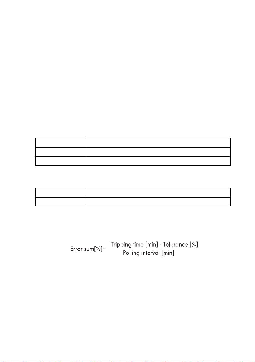
Error Sum
The error sum is a measure of the sensitivity of the string current monitoring. It can be parameterized
via the tripping time and tolerance, and is described by the following formula:
The individual error sums of the measuring channels are reset at 00:00 o'clock.
Installation Guide SSM16-24-IA-IEN105120 15
Page 16

3 Product Description SMA Solar Technology AG
Polling Interval
The Sunny String-Monitor continually measures the string currents and saves them in cycles. The data
logger reads these values every 5 minutes.
Tripping Time
The tripping time is the time span between the occurrence of a fault and the error message. The
tripping time is set to 180 minutes as default. You can set the parameters for the tripping time between
2 … 1440 minutes.
Tolerance
The tolerance indicates how much the string current may deviate fr om t he m ean value . Wh en t he s tring
current is outside of the tolerance limits, the data logger detects the deviation and stores it. The
tolerance can be set between 10% … 100%.
Grouping Strings
You can assign the strings to the 8 measuring channels in order to simplify monitoring. Should
individual PV strings be overshadowed, aligned differently or fitted with different modules, it is also
possible to group the individual measuring channels. This makes it possible to compare measuring
channels with the same properties.
Comparison
Every 5 minutes, the data logger compares the string-current with the mean value for the group. If the
string-current exceeds the tolerance limit, the data logger stores the deviation. If at the next poll, there
is still a deviation between the string-current and the mean value, the deviations are added together.
If the sum of deviations exceeds the error sum, the data logger sends the 380 "SMU" warning. When
the error is acknowledged, the error sum is reset, and the warning disappears from the display.
It is possible to see from the Sunny Central Control or via the Sunny WebBox which Sunny StringMonitor and which measuring channels are deviating from the mean value for the group.
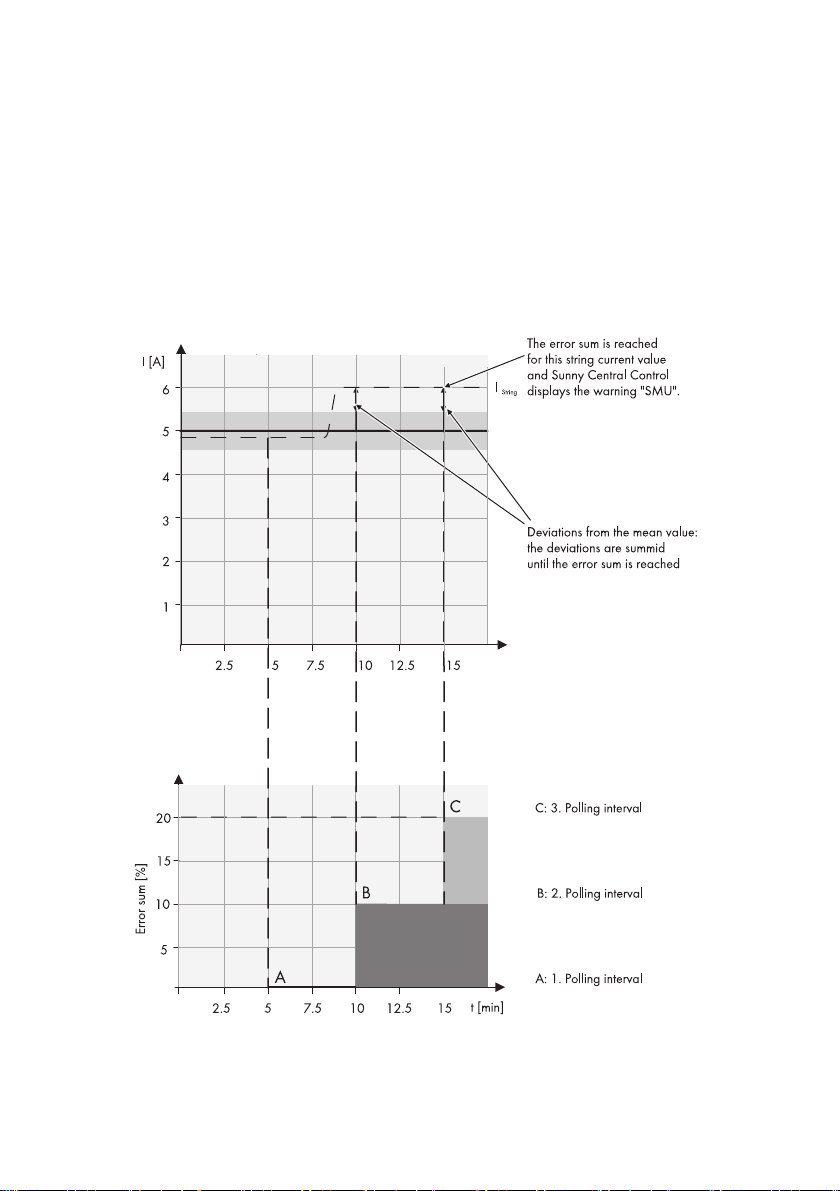
Example:
It is assumed that at time t0 the mean value of a group is 5 A. The set tolerance is 10%. This means
that the tolerance range is from 4.5 A … 5.5 A. The tripping time is set to 10 minutes. The polling
interval is 5 minutes. The error sum can therefore be calculated as follows:
16 SSM16-24-IA-IEN105120 Installation Guide
Page 17
SMA Solar Technology AG 3 Product Description
All the string currents are now compared to this mean value in the 5 minute polling interval. If all the
string currents lie within the set tolerance of 10%, no addition is carried out.
If, however, a string shows a string current of 6 A, then the difference between the actual string
current of 6 A and the tolerance limit of 5.5 A is added to the total. The difference is 0.5 A, which
is a deviation of 10% from the mean value. This difference of 10% is now added to the total until
the error sum of 20% is reached.
The error sum is reached when the error remains the same for two polling intervals. The data logger
sends the warning 380 "SMU".
Installation Guide SSM16-24-IA-IEN105120 17
Page 18

3 Product Description SMA Solar Technology AG
If a string fails, the current difference in the above example is 4.5 A, which equates to a deviation
of 90% from the mean value. If the settings in the above example remain the same, i.e. tolerance at
10% and tripping time at 10 minutes, the error sum of 20% is already reached after the first polling
interval of 5 minutes. The data logger now sends an "SMU" warning.
3.3 String Fuses
The string fuses protect the modules of a PV plant from reverse currents.
Figure3:The principle of reverse current
Reverse current can occur when different open-circuit voltages are applied to modules connected in
parallel. In this event, the reverse current can be much higher than the module's short-circuit current.
The higher the reverse current, the higher the heat will rise in the modules of the faulty PV string.
Pronounced warming can destroy the modules of the faulty PV string.
Reverse current can have the following causes:
• Short circuit in one or more modules
• Short circuit in one or more cells in a module
• Double ground fault in a module
• Double ground fault in the cabling
The string fuses trip when the string current is too high and thus protect the modules of the faulty PV
string. The Sunny String-Monitor informs Sunny Central Control of the failure of the PV string.
In the case of grounded PV arrays, the positive or the negative pole can be grounded at the inverter.
To do this, cylindrical bridges are fitted in the Sunny String-Monitor instead of fuses.
18 SSM16-24-IA-IEN105120 Installation Guide
Page 19

SMA Solar Technology AG 3 Product Description
3.4 Overvoltage Protection
Integrated surge arresters provide overvoltage protection. The surge arresters protect the inverters
from transient overvoltages. The integrated surge arresters can be monitored in the Sunny StringMonitor. To guarantee the functionality of the integrated surge arrester, this must be connected to an
external grounding. The connection to ground is provided by a ground terminal.
3.5 Remote Tripping
3.5.1 Remote Tripping as a Shunt Trip
The DC circuit breaker is fitted optionally with a remote trigger which is configured as a shunt trip.
The remote trigger with the shunt trip is used to switch off the DC circuit breaker in an electrically
controlled way. Action of the shunt trip is configured at a voltage between 70% … 110% of the
nominal voltage of the shunt trip U
tripped. The DC circuit breaker is controlled via a make contact.
The function of the shunt trip is not guaranteed if a cable breaks, a connection is loose, voltage is too
low or the voltage supply fails. We recommend the use of an uninterrupted voltage supply. The
activation time for safely activating the shunt trip is at least 3 seconds.
After it has been triggered remotely, the DC circuit breaker must be connected again manually.
. If a voltage is present at the shunt trip, the DC circuit breaker is
N
3.5.2 Remote Tripping as Undervoltage Release
Th e DC cir cui t br eak er i s fi tte d optiona lly wit h a r emo te t rig ger whi ch i s co nfi gur ed as an un der vol tag e
release.
Remote tripping with the undervoltage release is used to switch off the DC circuit breaker in an
electronically controlled way. The DC circuit breaker is tripped when there is no voltage at the
undervoltage release, or if the voltage falls below 85% of the nominal release voltage UN. After
tripping, the DC circuit breaker can be connected again after the voltage rises above 85% of the
undervoltage release nominal voltage UN.
In order to avoid an inadvertent tripping, we recommend an uninterrupted power supply. The
undervoltage release is designed for continuous operation. Activation takes place via a normally
closed contact. The minimum interruption time for reliable tripping of the undervoltage release is
1 second.
After it has been triggered remotely, the DC circuit breaker must be connected again manually.
3.6 Type Label
The purpose of the type label is to identify the Sunny String-Monitor. You will find the type label on
the inside of the right door and on the right external wall of the Sunny String-Monitor. You will find the
following information on the type label:
• Type (Type/Model)
•Serial number (Serial No.) of the Sunny String-Monitor
Installation Guide SSM16-24-IA-IEN105120 19
Page 20

4 Scope of Delivery SMA Solar Technology AG
4Scope of Delivery
4.1 Sunny String-Monitor SSM16-11
Check the scope of supply for completeness and any visible external damage. Please contact your
supplier if the delivery is not complete or you find any damage.
Figure4:Sunny String-Monitor SSM16-11 - scope of delivery
Position Quantity Designation
A 1 Sunny String-Monitor SSM16-11
B1Base
*
C 1 Switch cabinet key
D2Mounting rail
E8Screw
F 0/16 Cylindrical bridges
G 16/32 Fuses
H 32/64 DC plug connector +pole
20 SSM16-24-IA-IEN105120 Installation Guide
*
*
*
*
*
Page 21

SMA Solar Technology AG 4 Scope of Delivery
Position Quantity Designation
I 32/64 DC plug connector -pole
K 32/64 Sealing plugs for DC plug connectors
*
*
L 1 Installation guide
M 1 Circuit diagram
*
optional
4.2 Sunny String-Monitor SSM24-11
Check the scope of supply for completeness and any visible external damage. Please contact your
dealer if the delivery is not complete or you find any damage.
Figure5:Sunny String-Monitor SSM24-11 - scope of delivery
Position Quantity Designation
A 1 Sunny String-Monitor SSM24-11
B1Base
*
C 1 Switch cabinet key
D2Mounting rail
Installation Guide SSM16-24-IA-IEN105120 21
*
Page 22
4 Scope of Delivery SMA Solar Technology AG
Position Quantity Designation
E8Screw
F 0/24 Cylindrical bridges
G 24/48 Fuses
H 48/96 DC plug connector +pole
I 48/96 DC plug connector -pole
K 48/96 Sealing plugs for DC plug connectors
*
*
*
*
*
*
L 1 Installation guide
M 1 Circuit diagram
*
optional
22 SSM16-24-IA-IEN105120 Installation Guide
Page 23

SMA Solar Technology AG 5 Assembly
%"/(&3
5Assembly
5.1 Base Mounting
5.1.1 Selecting the Mounting Location
Danger to life due to fire or explosion.
• Do not install the Sunny String-Monitor on flammable construction materials.
• Do not install the Sunny String-Monitor near highly flammable materials.
• Do not install the Sunny String-Monitor in potentially explosive areas.
Requirements:
☐ The mounting location is not an escape route, nor in a residential or office area.
☐ The mounting location must be easily accessible for maintenance work.
☐ The mounting location is shaded.
☐ The mounting location is protected from rain as far as possible.
Installation Guide SSM16-24-IA-IEN105120 23
Page 24

5 Assembly SMA Solar Technology AG
1 060 mm
595 mm
595 mm
245 mm
Figure6:Arrangement of the cables in the base area
Position Designation
APV+ string cable
B Grounding cable, RS485 communications cable, cable for remote tripping
(optional)
C DC main cable to Sunny Central
DPV‒ string cable
5.1.2 Mounting the Base
Figure7:Dimension of the support for the base
24 SSM16-24-IA-IEN105120 Installation Guide
Page 25

SMA Solar Technology AG 5 Assembly
/05*$&
/05*$&
1. Dig a pit. Note the depth of the pit on the base. Tip: the maximum depth of the pit is marked on
the sides of the Sunny String-Monitor.
2. Set the base in the pit with the side of the kick plate facing forwards.
3. Remove the upper kick plate.
4. Presort the output cables according to location and place in the base.
5. Half-fill the pit with gravel or sand. Use a grain from 2 mm … 4 mm.
6.
Penetrating moisture can lead to condensation, corrosion, and leakage currents.
Using the base filler stops condensation forming.
• Fill the remaining space around the base with base filler. Use a grain from 4 mm … 8 mm.
5.1.3 Mounting the Sunny String-Monitor on the Base
Damage to the cable glands and plug connections due to improper transport and
installation.
The cable glands and plug connections protrude from the enclosure.
• When transporting and mounting the Sunny String-Monitor, ensure that the cable glands and
plug connections are not damaged.
1. Loosen the 4 fixing screws on the bottom plate of
the Sunny String-Monitor.
2. Remove the upper kick plate.
3. Place the Sunny String-Monitor on the base.
4. Fix the Sunny String-Monitor to the base using the screws that were previously removed.
5. Insert all the output cables through bottom plate into the Sunny Strong-Monitor, and fasten to
the internal cable support rail.
6. In order to stop the kick plate from being opened by unauthorized persons, fit the two safety
bolts to the inner side of the bottom plate.
Installation Guide SSM16-24-IA-IEN105120 25
Page 26

5 Assembly SMA Solar Technology AG
%"/(&3
5.2 Wall Mounting
5.2.1 Selecting the Mounting Location
Danger to life due to fire or explosion.
• Do not install the Sunny String-Monitor on flammable construction materials.
• Do not install the Sunny String-Monitor near highly flammable materials.
• Do not install the Sunny String-Monitor in potentially explosive areas.
☐ The mounting location is not an escape route, nor in a residential or office area.
☐ The mounting wall can support the weight of the Sunny String-Monitor.
☐ The mounting location must be easily accessible for maintenance work.
☐ Mounting location is shaded.
☐ The mounting location is protected from rain as far as possible.
• Include external cable support rail.
• Mount the Sunny String-Monitor so that the connection area is pointing downward.
• Do not mount the Sunny String-Monitor flat on its back or leaning.
• If the PV array has a stand, place the
SunnyString‑Monitor on the PV array stand in the
shade.
26 SSM16-24-IA-IEN105120 Installation Guide
Page 27

SMA Solar Technology AG 5 Assembly
/05*$&
5.2.2 Mounting the Sunny String-Monitor
Damage to the cable glands and plug connections due to improper transport and
installation.
The cable glands and plug connections protrude from the enclosure.
• When transporting and mounting the Sunny String-Monitor, ensure that the cable glands and
plug connections are not damaged.
Required Material:
• 4 screws with a diameter of 8 mm. Consider the wall properties when choosing the screws.
•4 washers
• 4 screw anchors. Consider the wall properties when choosing the screw anchors.
Figure8:SSM 16-11 dimensions
Installation Guide SSM16-24-IA-IEN105120 27
Page 28

5 Assembly SMA Solar Technology AG
Figure9:SSM 24-11 dimensions
1. Mark the position of the holes.
2. Drill the holes in the indicated positions.
3. Insert the screw anchors.
4. Attach the mounting rails to the
SunnyString‑Monitor with the screws supplied
(torque: 15 Nm).
5. Fasten the Sunny String-Monitor to the wall or stand using suitable screws. The connection area
must point downwards.
6. Make sure that the device is securely in place.
28 SSM16-24-IA-IEN105120 Installation Guide
Page 29

SMA Solar Technology AG 6 Electrical Connection
6 Electrical Connection
6.1 Overview of the Connection Area
Figure10:Terminals for connections
Position Designation
A Main DC cable connection, − pole
B DC-string connections − pole
C Grounding cable connection
D Connection for remote tripping
*
E Data cable connection
F DC-string connections, +pole
G Main DC cable connection, +pole
*
optional
Installation Guide SSM16-24-IA-IEN105120 29
Page 30

6 Electrical Connection SMA Solar Technology AG
B
A
C
D
Figure11:View of the Sunny String-Monitor from below (example)
Position Designation
ADrainage channels
B Cable entry for connecting the string +pole
*
C Cable entry for connecting the incoming data cable
D Cable entry for connecting the outgoing data cable
E Cable entries for connecting to the remote tripping device
F Cable entry for connecting the main DC cable +pole
**
G Cable entry for connecting the main DC cable +pole
H Cable entry for connecting the grounding cable
I Cable entry for connecting the main DC cable − pole
K Cable entry for connecting the main DC cable − pole
L Cable entry for connecting the strings − pole
*
optionally with DC connector
**
optional
**
*
Figure12:Operating status LEDs
Position LED Meaning
A LED 1, green Digital input, optional for theft protection
B LED 2, green Surge arrester
30 SSM16-24-IA-IEN105120 Installation Guide
Page 31

SMA Solar Technology AG 6 Electrical Connection
Position LED Meaning
C LED 3, orange Data transmission
D LED 4, red Failure of the control board
6.2 Connecting the PV Strings
6.2.1 Calculating the Maximum Number of Strings per Measuring Input
You can connect several PV strings in parallel in the Sunny String-Monitor. The maximum number of
PV strings connected in parallel depends on the adjustable tolerance and can be determined as
follows:
N = maximum number of PV strings that can be connected in parallel.
You can adjust the "Tolerance" parameter through the Sunny Central Control, Sunny Data Control or
Sunny WebBox, depending on the type of inverter.
Maximum Number of Strings
If you connect more PV strings than the calculated maximum, it is not possible to detect the
failure of one PV string.
• Adhere to the maximum number of PV strings which can be connected in parallel.
6.2.2 Connecting the PV Strings to Isolation Terminals
1. For each cable entry, remove the filler-plugs from the cable glands.
2. Guide the strings through the cable glands into the enclosure interior. Make sure polarity is
correct when doing this.
3. Cut the wires to length and strip 12 mm off the insulation.
4. Connect the wires to the isolation terminals. Make sure polarity is correct when doing this.
5. Tighten the cable glands.
6.2.3 Connecting the PV Strings to the SUNCLIX DC Plug Connectors
Requirement:
☐ There is one SUNCLIX DC plug connector for each string cable.
☐ PV1-F cable is available.
Installation Guide SSM16-24-IA-IEN105120 31
Page 32

6 Electrical Connection SMA Solar Technology AG
+
++
+
+
Procedure:
• Assemble the SUNCLIX DC plug connectors
• Connect the SUNCLIX DC plug connectors to the Sunny String-Monitor
Assemble the SUNCLIX DC plug connectors
Figure13:SUNCLIX DC plug connector
Position Designation
A Negative DC plug connector
B Positive DC plug connector
Use the following procedure to assemble each DC plug connector.
1. Cut the wire to length and strip 12 mm off the insulation.
2. Guide the stripped wire all the way into the DC
plug connector. Ensure the correctness of the
polarity assignment and of the type of plug.
3. Push the clamping clip downward.
☑ The clamping clip snaps audibly into place.
☑ The stranded wire can be seen inside the
clamping clip chamber.
32 SSM16-24-IA-IEN105120 Installation Guide
Page 33

SMA Solar Technology AG 6 Electrical Connection
+
1
2
+
1
2
✖ Is the stranded wire not visible in the chamber?
The stranded wire is not correctly in place.
• Declamp the clamping clip. To do this insert
a screwdriver with a 3.5 mm blade into the
clamping clip and pry it out.
• Remove the wire and start again from step 2.
4. Push the bolted connection toward the thread and
screw it tight (torque of 2 Nm).
Connect the SUNCLIX DC plug connectors to the Sunny String-Monitor
1. Remove the transport plugs from all the DC plug connectors.
2. Connect the assembled DC connectors to the Sunny String-Monitor.
☑ The DC connectors click audibly into position.
3. Ensure that all DC connectors are securely in place.
4. Insert the sea ling pl ugs int o the DC connec tors th at
are not required. This way you seal the DC plug
connectors.
Sealing plug
The sealing plugs included in the delivery are meant only for the DC plug connectors.
• Do not insert the sealing plugs into the DC inputs on the Sunny String-Monitor.
Installation Guide SSM16-24-IA-IEN105120 33
Page 34

6 Electrical Connection SMA Solar Technology AG
/05*$&
5. Insert the DC plug connectors with sealing plugs into the remaining DC inputs on the Sunny
String-Monitor. This way you seal the Sunny String-Monitor.
6.2.4 Connecting the PV Strings to Tyco, MC3, and MC4 Plug Connectors
1. Remove the sealing plugs from the plugs.
2. Connect the DC plug connectors.
6.3 Connecting the DC Main Cable
Damage to the electronics due to wrong cable installation.
In order for the Sunny String-Monitor and Sunny Central to work properly, EMC guidelines must be
observed.
• Lay the DC main cable and the data cable se parate ly and at a distance greater than 400 mm
from one another.
Requirement:
☐ The correct terminal cross section for the main DC cable has been chosen.
Terminal Cross Section for Copper Cable
Connection
terminal
maximum
240 mm
maximum
300 mm
*
Sunny String-Monitor SSM16/24-11 with bottom plate: connection of 1 cable per DC terminal possible.
**
Sunny String‑Monitor SSM16/24-11 without bottom plate: connection of 2 cables per DC terminal possible.
34 SSM16-24-IA-IEN105120 Installation Guide
2
2
Number of
cables
*
1
**
2
*
1
**
2
Round,
single-strand
25 mm2…
2
50 mm
25 mm2…
2
50 mm
- 150 mm2…
2
70 mm
Terminal cross section
Round,
multi-strand
25 mm2…
240 mm
25 mm2…
120 mm
300 mm
70 mm2…
185 mm
2
2
2
2
single-strand
50 mm2…
50 mm2…
150 mm2…
95 mm2…
Sectoral,
185 mm
120 mm
185 mm
185 mm
2
2
2
2
Sectoral,
multi-strand
35 mm2…
35 mm2…
150 mm2…
95 mm2…
240 mm
120 mm
240 mm
185 mm
2
2
2
2
Page 35

SMA Solar Technology AG 6 Electrical Connection
Terminal Cross Section of Aluminum Cable
Connection
terminal
maximum
240 mm
maximum
300 mm
*
Sunny String-Monitor SSM16/24-11 with bottom plate: connection of 1 cable per DC terminal possible.
**
Sunny String‑Monitor SSM16/24-11 without bottom plate: connection of 2 cables per DC terminal possible.
2
2
Number of
cables
*
1
**
2
*
1
**
2
Round,
single-strand
25 mm2…
2
50 mm
25 mm2…
2
50 mm
- 150 mm2…
2
70 mm
Terminal cross section
Round,
multi-strand
25 mm2…
240 mm
25 mm2…
120 mm
300 mm
70 mm2…
185 mm
2
2
2
2
single-strand
50 mm2…
50 mm2…
150 mm2…
95 mm2…
Sectoral,
185 mm
120 mm
185 mm
185 mm
2
2
2
2
Sectoral,
multi-strand
95 mm2…
185 mm
50 mm2…
2
95 mm
150 mm2…
240 mm
95 mm2…
185 mm
1. Remove filler-plugs from the cable glands.
2. Guide the DC main cable through the cable glands into the enclosure interior. Make sure
polarity is correct when doing this.
3. Strip the main DC cable appropriately for terminal used and attach it to cage clamps. Tighten
to the torque specified.
Terminal Stripped insulation Torque
240 mm² terminal 35 mm 40 Nm
300 mm² terminal 45 mm 50 Nm
2
2
2
4. Make sure that it is securely in place.
5. Tighten the cable glands.
6.4 Connecting the Grounding Cable
To guarantee the functionality of the integrated surge arrester, this must be connected to an external
earth.
Requirement:
☐ Minimum cross section of the grounding cable 16 mm
1. Remove the filler-plugs from the cable gland.
2. Guide the grounding cable through the cable gland into the enclosure interior.
3. Strip the grounding cable 16 mm.
4. Connect the grounding cable to the ground terminal (torque: 3.5 Nm).
5. Tighten the cable gland.
Installation Guide SSM16-24-IA-IEN105120 35
2
Page 36

6 Electrical Connection SMA Solar Technology AG
/05*$&
6. Ground the grounding cable in the vicinity of the Sunny String-Monitor, for example, with a
ground rod.
6.5 Connecting the Data Cable
6.5.1 Selecting the Data Cable
Damage to the electronics due to wrong cable installation.
In order for the Sunny String-Monitor and Sunny Central to work properly, EMC guidelines must be
observed.
• Lay the AC/DC main cable and the data cable separately and at a distance greater than
400 mm from one another.
• Lay the data cable shield in the Sunny Central and in the Sunny String-Monitor.
The data cable of the RS485 communication and the power supply connects the Sunny StringMonitor to the Sunny Central.
• Use a shared cable of type Li2YCYv (TP) 4 x 2 x 0.5 mm for the data cable of the RS485
communication and the +55 VDC voltage supply.
6.5.2 Connecting the Data Cable Shield Contact
1. Remove the filler-plugs from the cable gland.
2. Guide the data cables through the cable gland into the enclosure interior.
3. Remove the data cable cover.
4. Loosen the thumbscrew on the shield clamp and
pull the cable through. Lay the cable shield on the
shield rails as you do so.
Maximum shield diameter 8 mm
5. Only tighten the shield clamps hand-tight. This prevents any damage to the insulation.
6. Tighten the cable gland.
36 SSM16-24-IA-IEN105120 Installation Guide
Page 37

SMA Solar Technology AG 6 Electrical Connection
6.5.3 Connecting the Data Cable in the Sunny String-Monitor
Parallel Connection of the Data Cables
• If you are using several Sunny String-Monitors, connect them in parallel. This way there
will be an incoming and an outgoing data cable at every Sunny String-Monitor. Only
one incoming data cable is connected to the last Sunny String-Monitor.
You can use the Sunny String-Monitor SSM as well as the Sunny String-Monitor SSM16-11 and the
Sunny String-Monitor SSM24-11 for string monitoring. These have various numbers of Piggy-Backs
for data processing.
• Sunny String-Monitor SSM: 1 Piggy-Back for data processing.
• Sunny String‑Monitor SSM16-11: 2 Piggy-Backs for data processing.
• Sunny String-Monitor 24-11: 3 Piggy-Backs for data processing.
Limited Number of Piggy-Backs for Data Processing per Hub
The voltage supply to the measuring boards via the communication cables limits the number
of Sunny String-Monitors that can be connected.
• Connect a maximum of 10 Piggy-Backs for data processing per hub.
Installation Guide SSM16-24-IA-IEN105120 37
Page 38

6 Electrical Connection SMA Solar Technology AG
S
Figure14:Connection of the data cables between the Sunny String-Monitors
1. Strip 8 mm from each wire in the data cable.
2. Remove the sticker from the communication terminal strip.
3. Connect the wires of the data cable to the connection terminals. Observe the terminal
allocation.
4. Conduct the wiring between the individual Sunny String-Monitors in a bu s. O bse rve the ter min al
allocation of the data cable.
6.5.4 Connecting the Data Cable in the Sunny Central
For the Sunny Central 100/200/250/350 and the Sunny Central in the HE--11 series the Sunny
String-Monitor data cable is connected to the hub. There are twocommunications connections to
which up to 10 Piggy-Backs each can be connected for data processing.
For the Sunny Centrals in the CP and HE-20 series the SunnyString‑Monitor can be connected to a
dedicated terminal strip (please consult the installation guides for t he releva nt c entral invert ers for how
to connect the Sunny String-Monitors to the Sunny Centrals of the CP and HE-20 series). There are
threecommunications connections to which up to 10 Piggy-Backs each can be connected for data
processing.
38 SSM16-24-IA-IEN105120 Installation Guide
Page 39

SMA Solar Technology AG 6 Electrical Connection
Figure15:Connection of the data cables between the Sunny Central in the HE-11 series and the
SunnyString‑Monitors
1. Guide the data cable into the Sunny Central (see the installation guide for the Sunny Central in
question).
2. Strip 8 mm from each wire in the data cable.
3. Remove the sticker on the connection area of the hub.
4. Connect the wires of the data cable to the connection terminals on the hub in accordance with
the Sunny Central circuit diagram. Observe the terminal allocation of the data cable.
Installation Guide SSM16-24-IA-IEN105120 39
Page 40

6 Electrical Connection SMA Solar Technology AG
6.6 Connecting the Remote Tripping for the DC Circuit Breaker
6.6.1 Dimensioning the Connection Cable for the Shunt Trip
The Sunny String-Monitor optionally includes a DC circuit breaker with a remote trigger. The remote
trigger consists of a shunt release and a feedback contact. The shunt release can be implemented as
a shunt trip or undervoltage release.
In order to achieve reliable tripping, the minimum cross section of the connection cable on the shunt
trip must be determined. The choice of connection cable cross section depends on the following
factors:
• The number of Sunny String-Monitors connected
• The length of the cable supplying the voltage
• The cable lengths between the Sunny String-Monitors connected
Figure16:Relationship between cable length, number of Sunny String-Monitors connected and cable crosssection.
1. Determine the number of DC circuit breakers.
2. Determine the greatest distance between the Sunny String-Monitors or the voltage supply and
the first Sunny String-Monitor.
3. Read off the minimum cable cross section from figure 16.
Example: Dimensioning a Connection Cable
In a PV plant there are 20 DC circuit breakers. The greatest distance between the
SunnyString‑Monitors is 150 m.
The cable cross section must be at least 4 mm
40 SSM16-24-IA-IEN105120 Installation Guide
2
.
Page 41

SMA Solar Technology AG 6 Electrical Connection
/05*$&
6.6.2 Connecting the Shunt Release
De pen din g on the ord er, the Sun ny S tri ng- Mon ito r in clu des a DC circuit breaker with a remote trigger.
In this case the DC circuit breaker is equipped with a shunt release and a feedback contact.
Destruction of the shunt release due to faulty cable dimensioning.
If the cable cross section is too small, the shunt release can malfunction and be destroyed.
• If the shunt release is implemented as a shunt trip, the connection cable must be correctly
dimensioned (see section 6.6.1”Dimensioning the Connection Cable for the Shunt
Trip”,page40).
• If the shunt release is implemented as an undervoltage release, observe the requirements for
the connection cable.
Line Fuse
• Furnish the connection cable of the remote trigger with a suitable line fuse.
Requirements for the connection cable of the undervoltage release.
☐ Cable cross section: at least 2.5 mm
☐ Total cable length: 1 000 m maximum.
1. Remove the filler-plugs from the cable gland.
2. Guide the connection cable through the cable gland into the enclosure interior.
3. Strip the connection cable 14 mm.
4. Connect the connection cable to the terminal strip
as shown in the circuit diagram.
2
.
5. Tighten the cable gland.
6.6.3 Connecting the Feedback Contact
1. Remove the filler-plugs from the cable gland.
2. Guide the connection cable through the cable gland into the enclosure interior.
3. Strip the connection cable 11 mm.
Installation Guide SSM16-24-IA-IEN105120 41
Page 42

6 Electrical Connection SMA Solar Technology AG
4. Connect the connection cable to the terminal strip as
shown in the circuit diagram.
5. Tighten the cable gland.
6.7 Installing the Theft Protection
On the Sunny Central 100/200/250/350 inverters and the Sunny Central inverters in the HE‑11
series you can activate the theft protection for the PV modules via the Sunny String-Monitor.
The contacts at the PV modules are connected to form a signal chain for the theft protection. Upon
interruption of the signal chain, an theft warning appears in the Sunny Central Control display, and
an e-mail message is sent immediately.
Installation of the cable gland and wiring is carried out by the customer.
Nighttime deactivation
The theft protection only functions if the nighttime deactivation has been deactivated. If the
nighttime deactivation is activated, the message is not sent until the supply voltage has been
switched on again.
• Deactivate the nighttime deactivation for theft protection (see section 9.3.6”Setting the
Nighttime Deactivation”,page51).
Requirement:
☐ The signal chain has a maximum 300 Ohm loop resistor.
1. Implement the contacts at the PV modules as normally closed contacts and connect to form a
signal chain.
2. Integrate the signaling contact for the theft
protection on the String Monitor Unit into the
monitoring circuit.
3. Activate the theft protection via the Sunny Central Control or via Sunny Data Control (see
section 9.3.7”Setting the Theft Protection”,page52 or section 10.3.8”Setting the Theft
Protection”,page59)
42 SSM16-24-IA-IEN105120 Installation Guide
Page 43

SMA Solar Technology AG 7 Commissioning
7Commissioning
7.1 Safety
Electric Shock
The Sunny String-Monitor is connected to high voltages. Work on the Sunny String-Monitor is only
allowed if the power is disconnected and in compliance with the guidelines that apply at the
installation location.
• Disconnecting the device:
– Remove the DC fuses in the central inverter or main DC distributor, such as the Sunny Main
Box, in a no-load condition.
– Switch off the DC circuit breaker in the Sunny String-Monitor.
– Only open or close the isolation terminals in the Sunny String-Monitor in a no-load condition.
– Only insert or remove the fuses when wearing personal protective gear.
– Only plug in or unplug the solar plug when no current is present.
• Ensure that the device cannot be reconnected.
• Ensure that no voltage is present in the system.
• Ground and short-circuit.
• Cover or safeguard any adjacent live components. Protective covers must always be fitted.
7.2 Preparing and Carrying Out Commissioning
7.2.1 Requirements for Commissioning
The commissioning report must be filled out during commissioning. The commissioning report is
enclosed with the Sunny Central.
Requirements:
☐ The DC circuit breaker is disconnected.
☐ The DC main cables are connected to the inverter or DC distribution box and are activated.
There is no reverse voltage from the inverter.
☐ All connections are made according to this manual (see section 6”Electrical
Connection”,page29).
☐ The ground underneath the Sunny String-Monitors is firm and can be walked on.
7.2.2 Terminating the Data Cable
In each case, the last Sunny String-Monitor of a string and the hubs in the Sunny Central are
terminated.
Installation Guide SSM16-24-IA-IEN105120 43
Page 44

7 Commissioning SMA Solar Technology AG
The Sunny String-Monitors are not terminated on delivery so that they can be configured as required
on site. The hubs in the Sunny Central are terminated on delivery.
Figure17:Termination of the data cable (example)
Requirement:
☐ All Sunny String-Monitors on a string are connected to the RS485 bus (see section
6.5.3”Connecting the Data Cable in the Sunny String-Monitor”,page37 and section
6.5.4”Connecting the Data Cable in the Sunny Central”,page38).
1. Plug the jumper on the upper String Mon itor Un it into
the last Sunny String-Monitor of each string.
44 SSM16-24-IA-IEN105120 Installation Guide
Page 45

SMA Solar Technology AG 7 Commissioning
A
B
C
2. When the jumpers of the String Monitor Units of the other Sunny String-Monitors of the string
have been plugged in, remove the jumpers.
3. Make sure that the terminating resistor at the hub in the Sunny Central is plugged into the
"485 Out" RJ45 socket.
7.2.3 Noting the Serial Number of the Piggy-Backs for Data Processing
The serial number of the Piggy-Backs for data processing serves to identify the String Monitor Unit.
The position of the serial number depends on the production version of the Piggy-Back for data
processing.
All the serial numbers of the Piggy-Backs for data processing in all the Sunny String-Monitors must be
written down in the commissioning report. You need the serial numbers for detecting the
SunnyString‑Monitors.
Figure18:Possible position of the serial number
Position Designation
A Serial number on the left
B Serial number in the centre
C Serial number on the right
• Identify the serial numbers and note them in the commissioning report.
7.2.4 Filling In the Commissioning Report
• Check the following points and document them in the commissioning report:
– Polarity of the DC voltages at the string inputs and at the DC main cables.
– All strings have similar voltage values.
– Check for the absence of ground faults on the strings and the DC main cables.
– Inspect the screw connections visually.
– Fuses correspond to the system design.
Installation Guide SSM16-24-IA-IEN105120 45
Page 46

7 Commissioning SMA Solar Technology AG
%"/(&3
–The terminal allocation of the data cable is correct.
– All protective covers are fitted.
7.3 Switching On the Sunny String-Monitor
Requirement:
☐ Voltage supply for the measuring boards is present.
1. Remove protective covers.
2.
Risk of lethal electric shock.
• Disconnect the voltage from the Sunny String-Monitor before inserting the string fuses.
3. Replace the protective covers.
4. Connect up the isolation terminals in a no-load condition.
5. Activate the DC circuit breaker.
☑ O n th e co ntr ol cir cui t bo ard LED s 1 and 2 gl ow gre en a nd L ED 3 gl ows ora nge per iodic all y.
Theft protection and surge arrester are intact. Data cable and control circuit board are ok.
✖ On t he c ontrol ci rcu it b oar d, a re L ED 1 or LED 2 no t li t up , has LED 3 not lit up a fte r 5 minute s,
is LED 4 lit up and red?
• See section 12”Troubleshooting”,page68.
7.4 Reconnecting the DC Circuit Breaker after Tripping
If the PV array has been disconnected from the inverter with the remote trip in the
SunnyString‑Monitor, you must switch the DC circuit breaker on again manually.
1. Search for the cause of the tripping, and remove it.
2. Open the Sunny String-Monitor.
3. Switch the DC circuit breaker manually from the tripped position to the off position.
4. Switch the DC circuit breaker manually from the off position to the on position.
☑ The DC circuit breaker is switched to "On".
✖ Not possible to turn the DC circuit breaker?
The shunt release is activated.
• If the shunt release is a shunt trip, make sure there is no current at the shunt trip.
• If the shunt release is an undervoltage release, make sure that there is a voltage at the
undervoltage release.
5. Close the Sunny String-Monitor.
46 SSM16-24-IA-IEN105120 Installation Guide
Page 47

SMA Solar Technology AG 8 Disconnecting the Sunny String-Monitor
%"/(&3
%"/(&3
8"3/*/(
%"/(&3
8 Disconnecting the Sunny String-Monitor
Risk of lethal electric shock.
• Pay attention to the safety rules.
– Disconnecting the device
– Ensure that the device cannot be reconnected
– Ensure that no voltage or current is present
– Cover or isolate adjacent live elements
Risk of lethal electric shock. The discharge time of the capacitors is longer than 5 minutes.
• After disconnection, wait until the capacitors have discharged.
Danger of burns from touching hot component parts.
• Wear gloves when working on the device.
1. If there is a DC circuit breaker on the Sunny String-Monitor, disconnect it. This ensures that there
is no current flowing through the Sunny-String-Monitor.
2. If there is no DC circuit breaker, disconnect the Sunny Central (see the installation guide for the
Sunny Central).
3. If there are fuses in the Sunny Central, remove them. Use an LV/HRC fuse handle to do this.
4. If there are no fuses in the Sunny Central, remove the fuses in the DC main distributor.
5.
Risk of lethal electric shock.
• Only open the isolation terminals in a no-load condition.
6. Disconnect all the DC plug connectors.
Installation Guide SSM16-24-IA-IEN105120 47
Page 48

9 Configuring the Sunny String-Monitor via Sunny Central Control SMA Solar Technology AG
9 Configuring the Sunny String-Monitor via Sunny
Central Control
9.1 Organizing the Configuration
On the Sunny Central 100/200/250/350 inverters and the Sunny Central in the HE‑11 series, you
can configure the Sunny String-Monitor through the Sunny Central Control data logger. The Sunny
Central Control is integrated in the central inverter.
Consult the user manual for the central inverter on how to operate the Sunny Central Control and on
the meaning of the keys.
Password Protection
The installer password must be entered in order to configure the Sunny Central String-Monitor
in the Sunny Central Control (please see the user manual for the central inverter).
9.2 Detecting Sunny String-Monitors
Procedure:
• Setting the serial interface
• Detecting the Sunny String-Monitor
• Updating identification of the String Monitor Units
Setting the serial interface
Parameters of the COM1 interface are predefined and factory-set:
• Medium: RS485
• Baudrate: 19200 Baud
•Protocol: SMA-Net
1. Select Device Set-up > Interfaces > Communication > COM1:SMUs.
☑ The interface parameters appear:
2. If the parameters are not set as described above, correct them.
48 SSM16-24-IA-IEN105120 Installation Guide
Page 49

SMA Solar Technology AG 9 Configuring the Sunny String-Monitor via Sunny Central Control
Detecting Sunny String-Monitor
1. When you first detect the Sunny String-Monitor, delete any Sunny String-Monitors already
detected.
•Select Device Set-up > SMUs > Devices > Registration.
• Select the String Monitor Unit you want.
• Select the ID submenu.
• Set the ID number to 99.
• Adopt all changes with the [Enter] key.
2. Select Device Set-up > SMUs > Devices > Detection.
☑ The Sunny Central Control begins detection of new devices automatically.
✖ Are there any problems in detecting the Sunny Central String-Monitors?
• See section 12”Troubleshooting”,page68.
3. Adopt the changes and save them with the [Enter] key.
4. Select Device Set-up > SMUs > Devices > Registration.
5. Compare the serial numbers displayed with the serial numbers you noted (see section
7”Commissioning”,page43).
☑ All the noted serial numbers are on the list.
✖ Not all noted serial numbers are on the list?
• Start again with step 2.
Updating identification of the String Monitor Units
To identify the String Monitor Units in the Sunny String-Monitor, each Piggy-Back for data processing
is assigned a number as an "SSM identifier". This makes troubleshooting easier, for example, in the
event of a string failure, or deviating string currents. The "SSM Identifier" does not correspond to the
network address which is automatically assigned upon detection. The Su nny Central Control support s
up to 40 "SSM Identifiers".
1. Select Device Set-up > SMUs > Devices > Parameters.
2. Select the String Monitor Unit you want.
3. Select the SSM Identifier parameter.
4. Give the String Monitor Unit you want a unique identification number between 1 and 40.
5. Adopt all changes with the [Enter] key.
Installation Guide SSM16-24-IA-IEN105120 49
Page 50

9 Configuring the Sunny String-Monitor via Sunny Central Control SMA Solar Technology AG
9.3 Setting the Parameters for the String Current Monitoring
9.3.1 Setting the Number of Strings per Measuring Channel
The number of strings per channel for the eight measuring channels can be selected from 1 to 4. The
default setting is "1". The maximum number of strings per channel is limited to 4.
The ideal number of strings for each measuring channel is 2. Depending on the system design it is
possible to connect more strings in parallel outside the Sunny String-Monitor and append them to a
measuring channel (see section 6.5.3”Connecting the Data Cable in the Sunny StringMonitor”,page37).
In the submenu No. of Str. All you can assign all channels of the Sunny String-Monitor to a string
number of 1 to 4.
No strings in a measuring channel
• If there are no strings connected to a measuring channel, assign this channel to the
0 group (see section 9.3.2”Setting the Groups”,page50).
1. Select Device Set-up > SMUs > Devices > Parameters.
2. Select the String Monitor Unit you want.
3. In the submenu No. Of Strings or No. of Str. All set the number of strings connected per
measuring channel used.
9.3.2 Setting the Groups
With Sunny Central Control one can subdivide the individual measuring channels of the connected
String Monitor Units into 3 groups, to make it possible to compare only th e measu ring ch annels which
have the same properties. The groups are monitored independently of each other, and each
individual measuring channel can be allocated freely to any group. An individual group must include
at least 4 measuring channels.
In the Group all chan. all the measuring channels of the String Monitor Unit can be assigned to a
group.
If you wish not to include individual channels from the String Monitor Unit in the string current
monitoring, these must be assigned to the 0 group, since string current monitoring is deactivated for
this group. This way, this measuring channel is not included in the mean value calculation.
1. Select Device Set-up > SMUs > Devices > Parameters.
2. Select the String Monitor Unit you want.
3. In the Group channel or Group all chan. submenu, set the group numbers for individual
measuring channels or for all of them.
50 SSM16-24-IA-IEN105120 Installation Guide
Page 51

SMA Solar Technology AG 9 Configuring the Sunny String-Monitor via Sunny Central Control
9.3.3 Setting the Tripping Time
Using the tripping time, you can set the sensitivity of the string current monitoring, since it is included
in the calculation of the error sum. The tripping time is set to 180 minutes as default.
1. Select Device Set-up > SMUs > Parameters.
2. In the Error Report Time submenu, set the value in minutes.
9.3.4 Setting the Tolerance
You can use the tolerance to set the sensitivity of the string current monitoring, since it is included in
the calculation of the error sum. The tolerance is set to 10% as default.
Since only a clear deviation of a measuring channel from a mean value is an indication of a faulty
string, whereas minor deviations can be considered normal, the tolerance value must be set
accordingly high.
1. Select Device Set-up > SMUs > Parameters
2. In the submenu tolerance grp, set the value per group.
9.3.5 Setting the Monitoring Period
You can define a monitoring period for each individual measuring channel on the Sunny StringMonitor. This allows you to filter out temporary effects such as shading on individual strings.
Under Monitoring On and Monitoring Off, one can set a specific time window for all measuring
channels of the Sunny String-Monitor for string current monitoring.
1. Select Device Set-up > SMUs > Devices > Parameters.
2. Select the String Monitor Unit you want.
3. In the submenu Monitoring (X) On and Monitoring (X) Off, one can set a specific time
window per measuring channel or for all the measuring channels of the Sunny String-Monitor.
9.3.6 Setting the Nighttime Deactivation
Nighttime deactivation in the Sunny Central is activated by default. Thus, the power supply to the
Sunny String-Monitors is deactivated in the Sunny Central as soon as the PV voltage has been under
250 V for one hour. The supply voltage switches itself on as soon as the PV voltage reaches 250V.
If nighttime deactivation is deactivated, the supply voltage to the Sunny String-Monitor remains on at
night. This means that theft protection can be activated and evaluated, see section 9.3.7”Setting the
Theft Protection”,page52.
1. Select Device Set-up > SMUs > Parameters.
2. In the submenu SMU Overn. Shut, set the nighttime disconnection.
Installation Guide SSM16-24-IA-IEN105120 51
Page 52

9 Configuring the Sunny String-Monitor via Sunny Central Control SMA Solar Technology AG
9.3.7 Setting the Theft Protection
Theft protection is deactivated by default in Sunny Central Control.
1. Select Device Set-up > SMUs > Parameters.
2. In the SMU Theft. submenu, set the theft protection.
9.4 Reading the Measured Values
9.4.1 Reading the Mean Values of the Groups
The mean values of the measuring channels for each group are displayed and updated at 5 minute
intervals.
•Select Device Set-up > SMUs > Measured Values and read the values.
9.4.2 Reading the Mean Values for the Individual Measuring Channels
The mean values for the individual measuring channels are updated and displayed at 5-minute
intervals.
•Select Device Set-up > SMUs > Devices > Measured Values and read the values.
9.5 Reading and Confirming Messages
9.5.1 Resetting the Messages
The individual meanings of the warnings and failures in the Sunny Central Control can be found in the
Sunny Central user manual.
Sunny Central Control resets messages which appear during a day automatically at midnight. These
messages can be read the next day in the event history. The individual error sums of the measuring
channels are reset at 00:00 o'clock.
9.5.2 Reading and Confirming Current Messages
1. Select Device Set-up > SMUs > Failure > actual Failures.
2. To confirm the message, select the submenuSMU Error quit. By doing this, you reset the error
sum.
9.5.3 Reading and Confirming the Event History
1. Select Device Set-up > SMUs > Failure > Hist. Failures.
2. To confirm the message, select the submenu SMU Error quit. By doing this, you reset the error
sum.
52 SSM16-24-IA-IEN105120 Installation Guide
Page 53

SMA Solar Technology AG 10 Configuring the Sunny String-Monitor with Sunny Data Control
10 Configuring the Sunny String-Monitor with Sunny
Data Control
10.1 Organizing the Configuration
For the Sunny Central 100/200/250/350 inverters and the Sunny Central of the HE‑11 series, you
can configure the Sunny String-Monitor with the Sunny Data Control program.
Sunny Data Control is a PC program by SMA Solar Technology AG with which you can store your
PV plant data in the long term and visualize it. Sunny Data Control can be downloaded free from
www.SMA.de/en (For information on how to use Sunny Data Control, see the Sunny Data Control
user manual at www.SMA.de/en).
Sunny Data Control Version
• Use Sunny Data Control up to version 3.9.3 to configure the Sunny String-Monitor.
Password Protection
In order to change parameters, entering the installer password is required. Contact the
SMA Serviceline about this (please see the user manual for Sunny Data Control at
www.SMA.de/en for information about password protection).
If you re-install Sunny Data Control on your PC, default values are set for this new version. To allow
communication with Sunny Central Control, these values must be modified as follows:
Property Default value Value for Sunny Central Control
Channel request 10 s 200 s
Storage time request 10 s 200 s
Detection Find First 5 s 10 s
Detection Find Next 7 s 10 s
Installation Guide SSM16-24-IA-IEN105120 53
Page 54

10 Configuring the Sunny String-Monitor with Sunny Data Control SMA Solar Technology AG
Figure19:Window for setting of required values
Position Designation
A Tree structure
B"Settings" area
C Parameters to be set
D"Value" field
E[OK] button
1. Choose Options > Settings
☑The "Settings" window opens.
2. In the tree structure, select Timing.
3. In the "Properties" area, select Meanval Request > Channel Request.
4. In the box "Value", enter 200.
5. In the "Properties" area, select Meanval Request > Storage Time Request.
6. In the box "Value", enter 200.
7. In the "Properties" area, select Device Detection > Detection Find First.
8. In the box "Value", enter 10.
9. In the area "Settings", select Device Detection > Detection Find Next.
10. In the box "Value", enter 10.
11. Select [OK].
54 SSM16-24-IA-IEN105120 Installation Guide
Page 55

SMA Solar Technology AG 10 Configuring the Sunny String-Monitor with Sunny Data Control
10.2 Detecting the Sunny String-Monitor
Figure20:Buttons and input windows for configuring the Sunny String-Monitor
Position Designation
A[Search] button to detect devices
B Labeling of the String-Monitor with the serial number of the piggy-back for
data processing in the plant tree
C"Parameters" tab
D"Parameters" area
E"Channel value" area
F[Set] button
Requirement:
☐ Piggy-Backs for data processing are detected in Sunny Central Control (see section
9.2”Detecting Sunny String-Monitors”,page48).
1. Select [Search].
☑ Sunny Data Control starts detecting new devices.
✖ Are there any problems in detecting the Sunny Central String-Monitors?
• See Section .12”Troubleshooting”,page68
2. Compare the serial numbers detected in the plant tree with the serial numbers noted down
(see section 7”Commissioning”,page43).
☑ All serial numbers that were noted down are in the plant tree.
Installation Guide SSM16-24-IA-IEN105120 55
Page 56

10 Configuring the Sunny String-Monitor with Sunny Data Control SMA Solar Technology AG
✖ Not all indicated serial numbers are on the system tree?
• Start again with step 2.
3. Adapt the identification process for each String Monitor Unit.
• Select the String Monitor Unit you want.
• In the "Parameters" area, select SSM Identifier.
•In the "Channel Value" area, enter a unique identification number between 1 and 40.
•Select [Set]. This saves the setting.
10.3 Setting Parameters for String Current Monitoring
10.3.1 Overview of the Program Window
Figure21:Buttons and input windows for parameterization of the Sunny String-Monitor
Position Designation
A Second-tier designation of the device in the plant tree
B Labeling of the String Monitor Unit with the serial number of the Piggy-Back
for data processing in the plant tree
C"Parameters" tab
D"Parameters" area
E"Channel value" area
F[Set] button
56 SSM16-24-IA-IEN105120 Installation Guide
Page 57

SMA Solar Technology AG 10 Configuring the Sunny String-Monitor with Sunny Data Control
10.3.2 Setting the Number of Strings per Measuring Channel
The number of strings per channel for the eight measuring channels can be selected from 1 to 4. The
default setting is "1". The maximum number of strings per channel is limited to 4.
The ideal number of strings for each measuring channel is 2. Nevertheless one can, depending on the
system design, connect more strings in parallel outside the Sunny String-Monitor and append them to
a measuring channel (see section 6.5.3”Connecting the Data Cable in the Sunny StringMonitor”,page37).
In the submenu No. of Str. All you can assign all channels of the Sunny String-Monitor to a string
number of 1 to 4. This avoids having to set the number of strings for each of the individual channels,
since this is automatically set for all the individual channels.
1. Select the String Monitor Unit you want in the plant tree.
2. In the "Parameters" area, click No. Of Strings for the desired channel, or No. of Str. All.
3. In the area "Channel value", enter the number of PV strings per channel or for all channels.
4. Select [Set]. This saves the setting.
10.3.3 Setting the Groups
You can subdivide the individual measuring channels of the connected String Monitor Units into 3
groups, to make it possible to compare the measuring channels which have the same properties. The
groups are monitored independently of each other, and each individual measuring channel can be
allocated freely to any group. An individual group must include at least 4 measuring channels.
In the Group all chan. all the measuring channels of the String Monitor Unit can be assigned to a
group. This avoids having to allocate the individual measuring channels to a group as this then occurs
automatically for all the individual measuring channels.
If you wish not to include individual channels from the String Monitor Unit in the string current
monitoring, these must be assigned to the 0 group, since string current monitoring is deactivated for
this group. This way, this measuring channel is not included in the mean value calculation.
1. Select the String Monitor Unit you want in the plant tree.
2. In the "Parameters" area, select Group channel for the desired channel, or Group all chan.
3. In the area "Channel value", enter the number the group per channel of for all channels.
4. Select [Set]. This saves the setting.
10.3.4 Setting the Monitoring Period
You can define a monitoring period for each individual measuring channel on the Sunny StringMonitor. This allows you to filter out temporary effects such as shading on individual strings.
Installation Guide SSM16-24-IA-IEN105120 57
Page 58

10 Configuring the Sunny String-Monitor with Sunny Data Control SMA Solar Technology AG
Under Monitoring On and Monitoring Off, one can set a specific time window for all measuring
channels of the Sunny String-Monitor for string current monitoring.
1. Select the String Monitor Unit you want in the plant tree.
2. In the area "Parameter", Monitoring (X) On for the desired channel or Monitoring On for the
complete Sunny String-Monitor.
3. In the area "Channel value" enter the desired time of day starting at which the measuring
channel or the Sunny String-Monitor should be monitored.
4. Select [Set]. This saves the setting.
5. In the area "Parameter", select Monitoring (X) Off for the desired channel or Monitoring Off
for the complete Sunny String-Monitor.
6. In the area "Channel value" enter the desired time of day up to which the measuring channel or
the Sunny String-Monitor should be monitored.
7. Select [Set]. This saves the setting.
10.3.5 Setting the Tripping Time
Using the tripping time, you can set the sensitivity of the string current monitoring, since it is included
in the calculation of the error sum. The tripping time is set to 180 minutes as default.
1. Select the device on the second tier of the plant tree.
2. In the area "Parameters", select SMU_Error Report Time.
3. In the area "Channel value" enter the desired value in minutes.
4. Select [Set]. This saves the setting.
10.3.6 Setting the Tolerance
Using the tolerance, you can set the sensitivity of the string current monitoring, since it is included in
the calculation of the error sum. The tolerance is set to 10% as default.
1. Select the device on the second tier of the plant tree.
2. In the "Parameters" area, select SMU_ToleranceGrp for the required group.
3. In the area "Channel value" enter the desired value in percent.
4. Select [Set]. This saves the setting.
10.3.7 Setting the Nighttime Deactivation
1. Select the device on the second tier of the plant tree.
2. In the "Parameters" area, click on SMU_Nachtab.
3. In the area "Channel value", select On or Off from the drop-down list.
4. Select [Set]. This saves the setting.
58 SSM16-24-IA-IEN105120 Installation Guide
Page 59

SMA Solar Technology AG 10 Configuring the Sunny String-Monitor with Sunny Data Control
10.3.8 Setting the Theft Protection
1. Select the device on the second tier of the plant tree.
2. In the area "Parameter", select SMU_Diebstahl.
3. In the area "Channel value", select On or Off from the drop-down list.
4. Select [Set]. This saves the setting.
10.4 Reading the Measured Values
Su nny Dat a Control off ers various m eth ods for displ ayi ng t he current measured values (for information
about options for displaying values, please see the user manual for Sunny Data Control at
www.SMA.de/en).
Figure22:Program window for reading spot values (example)
Position Designation Explanation
A"Spotvalues" tab -
B Sunny String-Monitor window with the
list of spot values
C Sunny Central Control window with the
list of spot values
Installation Guide SSM16-24-IA-IEN105120 59
The window shows the list of spot values.
The window shows the mean values of the
measuring channels for each group.
Page 60

11 Configuring the Sunny String-Monitor with Sunny WebBox SMA Solar Technology AG
11 Configuring the Sunny String-Monitor with
Sunny WebBox
11.1 Organizing the Configuration
With the Sunny Central inverters in the CP series or Sunny Central in the HE-20 series, the string
currents are analyzed with the Sunny Central String-Monitor Controller.
With the Sunny Central 100/200/250/350 inverters or Sunny Central in the HE-11 series, the string
currents are analyzed with Sunny Central Control.
Sunny String-Monitors in the Sunny Central 100/200/250/350 inverters or Sunny Central in the
HE-11 series are detected through Sunny Central Control (see section 9.2”Detecting Sunny StringMonitors”,page48). Sunny String-Monitors in the Sunny Central inverters in the CP series or
Sunny Central in the HE-20 series can be identified through the Sunny WebBox.
Setting parameters and confirming error messages depends on the type of central inverter and the
type of data logger.
11.2 Sunny WebBox Interface Overview
Figure23:Navigation bar and areas of the Sunny WebBox interface
Position Designation
A Navigation bar
BPlant Tree
CContent area with tabs
60 SSM16-24-IA-IEN105120 Installation Guide
Page 61

SMA Solar Technology AG 11 Configuring the Sunny String-Monitor with Sunny WebBox
11.3 Detecting the Sunny Central
1. Access the Sunny WebBox interface.
2. Enter installer's password and confirm with [Login].
3. Detect Sunny Central:
•Select "Detection" in the Navigation bar.
•In the "Total number of devices to be detected" field, enter 1.
•Select [Start detection].
☑ The Sunny WebBox starts detecting all the devices and displays its progress. The message
"Device detection finished" is displayed.
4. Select [OK].
11.4 Detecting the Sunny String-Monitor
1. Select the "Parameters" tab.
2. When you detect Sunny String‑Monitors for the first time, delete any that have already been
detected:
•In the "DevFunc" parameter, select DelAll_SSMU.
•Select [Save].
3. In the "DevFunc" parameter, select AutoDetect_SSMU.
4. Select [Save].
☑ The message "Parameters changed successfully" is displayed.
5. Select [OK].
6. Select the "Spot values" tab.
7. Check the number of String Monitor Units detected in the parameter field "SSMUNoOF".
☑ All the String Monitor Units have been detected.
✖ Not all the Sunny String-Monitor units have been detected?
• Select the "Parameters" tab.
•In the "DevFunc" parameter, select DetectSSMURetry.
• Proceed with step 4.
8. Select "Detection" in the Navigation bar.
9. In the "Total number of devices to be detected" field, enter the number of the String Monitor Units.
10. Select [Start detection].
☑ The Sunny WebBox starts detecting all the devices and displays its progress. The message
"All devices found" is displayed.
✖ Is it taking too long to detect the Sunny String-Monitors?
• See Section 12”Troubleshooting”,page68.
Installation Guide SSM16-24-IA-IEN105120 61
Page 62

11 Configuring the Sunny String-Monitor with Sunny WebBox SMA Solar Technology AG
11. Select [OK].
12. Adapt the identification process for each String Monitor Unit.
• Select the required String Monitor Unit in the plant tree.
• Select the "Parameters" tab.
• Enter a value between 1 and 40 in the parameter field "SSM Identifier".
•Select [Save].
11.5 Setting the Parameters for Sunny Central Control
11.5.1 Setting the Number of Strings per Measuring Channel
The number of strings per channel for the eight measuring channels can be selected from 1 to 4. The
default setting is "1". The maximum number of strings per channel is limited to 4.
The ideal number of strings for each measuring channel is 2. Nevertheless one can, depending on the
system design, connect more strings in parallel outside the Sunny String-Monitor and append them to
a measuring channel (see section 6.5.3”Connecting the Data Cable in the Sunny StringMonitor”,page37).
With the parameter "No.of Strings" you can assign all the measuring channels of the
SunnyString‑Monitor to a string number of 1 to 4. This avoids having to set the number of strings for
each of the individual channels, since this is automatically set for all the individual channels.
1. Select the String Monitor Unit you want in the plant tree.
2. Select the "Parameters" tab.
3. Enter the number of PV strings per measuring channel in the parameter fields "No.of Strings 1"
to "No.of Strings 8" or enter the number of PV strings for all the measuring channels in the
"No.of Strings" field.
4. Select [Save].
11.5.2 Setting the Groups
Sunny Central Control allows the individual measuring channels to be subdivided into 4 groups, to
make it possible to compare only those measuring channels which have the same properties.
You can assign all the measuring channels to one group in the field of the "Group String" parameter.
If you wish not to include individual channels from the String Monitor Unit in the string current
monitoring, these must be assigned to the 0 group, since string current monitoring is deactivated for
this group. This way, this measuring channel is not included in the mean value calculation.
1. Select the String Monitor Unit you want in the plant tree.
2. Select the "Parameters" tab.
3. Enter the number of the group for each measuring channel in the parameter fields
"Group String 1" to "Group String 8" or in the "Group String" parameter field, enter the number
of the group for all the measuring channels.
4. Select [Save].
62 SSM16-24-IA-IEN105120 Installation Guide
Page 63

SMA Solar Technology AG 11 Configuring the Sunny String-Monitor with Sunny WebBox
11.5.3 Setting the Monitoring Period
You can define a monitoring period for every measuring channel. This allows you to filter out
temporary effects such as shade on the group of PV strings.
You can set a monitoring period for all the measuring channels in the parameter field "Monitoring On"
and "Monitoring Off".
1. Select the String Monitor Unit you want in the plant tree.
2. Select the "Parameters" tab.
3. In the parameter fields "Monitoring 1 On" to "Monitoring 8 On" or "Monitoring On" set the start
of the monitoring period for each measuring channel or all the measuring channels.
4. In the parameter fields "Monitoring 1 Off" to "Monitoring 8 Off" or "Monitoring Off", set the end
of the monitoring period for each measuring channel or all the measuring channels.
5. Select [Save].
11.5.4 Setting the Tripping Time
Using the tripping time, you can set the sensitivity of the string current monitoring, since it is included
in the calculation of the error sum. The tripping time is set to 180 minutes as default.
1. Select the required Sunny Central Control in the plant tree.
2. Select the "Parameters" tab.
3. In the parameter field "SMU_T_Ausl." enter the tripping time in minutes.
4. Select [Save].
11.5.5 Setting the Tolerance
You can use the tolerance to set the sensitivity of the string current monitoring, since it is included in
the calculation of the error sum.
Since only a clear deviation of a measuring channel from a mean value is an indication of a faulty
string, whereas minor deviations can be considered normal, the tolerance value should be set
accordingly high.
1. Select the required Sunny Central Control in the plant tree.
2. Select the "Parameters" tab.
3. Enter the tolerance value in percent for the groups in the parameter fields
"SMU_tolerance grp1" to "SMU_tolerance grp3".
4. Select [Save].
Installation Guide SSM16-24-IA-IEN105120 63
Page 64

11 Configuring the Sunny String-Monitor with Sunny WebBox SMA Solar Technology AG
11.6 Setting the Parameters for the Sunny Central String Monitor Controller
11.6.1 Setting the Number of Strings per Measuring Channel
The number of strings per channel for the eight measuring channels can be selected from 1 to 4. The
default setting is "1". The maximum number of strings per channel is limited to 4.
The ideal number of strings for each measuring channel is 2. Nevertheless one can, depending on the
system design, connect more strings in parallel outside the Sunny String-Monitor and append them to
a measuring channel (see section 6.5.3”Connecting the Data Cable in the Sunny StringMonitor”,page37).
With the parameter "No.of Strings" you can assign all the measuring channels of the Sunny
String-Monitor to a string number of 1 to 4. This avoids having to set the number of strings for each of
the individual channels, since this is automatically set for all the individual channels.
1. Select the String Monitor Unit you want in the plant tree.
2. Select the "Parameters" tab.
3. In parameter fields "No.of Strings 1" to "No.of Strings 8" enter the number of PV strings per
measuring channel or in the field "No.of Strings" the number of PV strings for all the measuring
channels.
4. Select [Save].
11.6.2 Setting the Groups
Sunny Central Control allows the individual measuring channels to be subdivided into 4 groups, to
make it possible to compare only those measuring channels which have the same properties.
You can assign all the measuring channels to one group in the field of the "Group String" parameter.
If you wish not to include individual channels from the String Monitor Unit in the string current
monitoring, these must be assigned to the 0 group, since string current monitoring is deactivated for
this group. This way, this measuring channel is not included in the mean value calculation.
1. Select the String Monitor Unit you want in the plant tree.
2. Select the "Parameters" tab.
3. Enter the number of the group for each measuring channel in the parameter fields
"Group String 1" to "Group String 8" or in the "Group String" parameter field, enter the number
of the group for all the measuring channels.
4. Select [Save].
64 SSM16-24-IA-IEN105120 Installation Guide
Page 65

SMA Solar Technology AG 11 Configuring the Sunny String-Monitor with Sunny WebBox
11.6.3 Setting the Communication Period
Th e co mmu nic ati on p eriod is t he t ime per iod dur ing whi ch t he S unny Central String-Monitor Controller
communicates with the Sunny String-Monitors. The communication period is set to 10:00 a.m. to 3:00
p.m. by default.
1. Select the Sunny Central StringMonitor Controller you want in the plant tree.
2. Select the "Parameters" tab.
3. Set the communication period in the parameter fields "MoniTmComOn" und "MoniTmComOff".
4. Select [Save].
11.6.4 Setting the Monitoring Period
You can define a monitoring period for each of measuring channels. This allows you to filter out
temporary effect s such a s shade on the g roup of PV stri ngs. Th e monitoring period is set to 10:00 a.m.
to 3:00 p.m. by default.
You can set the monitoring period for all the groups in the parameter fields "MoniTmGrAllOn" und
"MoniTmGrAllOff".
1. Select the Sunny Central StringMonitor Controller you want in the plant tree.
2. Select the "Parameters" tab.
3. Set the start time for the monitoring period for each group or for all the groups in the parameter
fields "MoniTmGr1On" to "MoniTmGr6On" or "MoniTmGrAllOn".
4. Set the end time for the monitoring period for each group or for all the groups in the parameter
fields "MoniTmGr1Off" to "MoniTmGr6Off" or "MoniTmGrAllOff".
5. Select [Save].
11.6.5 Setting the Tripping Time
Using the tripping time, you can set the sensitivity of the string current monitoring, since it is included
in the calculation of the error sum. The tripping time is set to 35 minutes as default.
1. Select the Sunny Central String Monitor Controller you want in the plant tree.
2. Select the "Parameters" tab.
3. Enter the tripping time for each group in the parameter fields "TrgTmGr1" to "TrgTmGr6" in
minutes.
4. Select [Save].
Installation Guide SSM16-24-IA-IEN105120 65
Page 66

11 Configuring the Sunny String-Monitor with Sunny WebBox SMA Solar Technology AG
11.6.6 Setting the Tolerance
You can use the tolerance to set the sensitivity of the string current monitoring, since it is included in
the calculation of the error sum. The default tolerance setting for each group is 13%.
Since only a clear deviation of a measuring channel from a mean value is an indication of a faulty
string, whereas minor deviations can be considered normal, the tolerance value must be set
accordingly high.
1. Select the Sunny Central String Monitor Controller you want in the plant tree.
2. Select the "Parameters" tab.
3. Enter the tolerance value for the groups in percent in the parameter fields "TolGr1" to "TolGr6".
4. Select [Save].
11.7 Reading the Measured Values
11.7.1 Reading the Measured Values of the Groups
1. Access the Sunny WebBox interface.
2. Enter the user password and confirm with [Login].
3. Select the Sunny Central String Monitor Controller you want in the plant tree.
4. Read off the mean values for the groups on the "Spot values" tab.
11.7.2 Reading the Measured Values for the Individual Measuring Channels
1. Access the Sunny WebBox interface.
2. Enter the user password and confirm with [Login].
3. Select the String Monitor Unit you want from the plant tree.
4. Read the mean values for the individual measuring channels on the "Spot values" tab.
66 SSM16-24-IA-IEN105120 Installation Guide
Page 67

SMA Solar Technology AG 11 Configuring the Sunny String-Monitor with Sunny WebBox
11.8 Acknowledging Error Messages
11.8.1 Acknowledging Error Messages with Sunny Central Control
1. Access the Sunny WebBox interface.
2. Enter the user password and confirm with [Login].
3. Select the Sunny Central Control you want in the plant tree.
4. Select the "Parameters" tab.
5. Select Quit in the drop-down list for the "SMU_QuitSMU" parameter.
6. Select [Save]. You have acknowledged the current error message.
11.8.2 Acknowledging Error Messages with the Sunny Central String Monitor Controller
1. Select the Sunny Central String Monitor Controller you want in the plant tree.
2. Select the "Parameters" tab.
3. Select Quit in the drop-down list for the "Ackn" parameter.
4. Select [Save]. You have acknowledged the current error message.
Installation Guide SSM16-24-IA-IEN105120 67
Page 68

12 Troubleshooting SMA Solar Technology AG
12 Troubleshooting
12.1 LED signals
Symptom Cause Corrective measures
LED not lighting up. Problems with the power supply • Check the +55 V power
supply at the connection area
of the Sunny String-Monitor in
question.
LED 1 does not glow. Theft protection is activated. • Check the wiring of the theft
protection.
LED 2 does not glow. Surge arrester has tripped. • Replace a defective
protection module in the surge
arrester.
LED 3 does not light up for
more than 5 minutes.
LED 4 glows red. Failure of the control board of
Problems with the data cable • Check data cable between
Sunny Central and Sunny
String-Monitor, and between
the individual Sunny
String-Monitors.
• Contact the SMA Serviceline.
the string current monitoring
68 SSM16-24-IA-IEN105120 Installation Guide
Page 69

SMA Solar Technology AG 12 Troubleshooting
12.2 Communication and Operation Faults
Symptom Cause Corrective measures
Problems in detecting the
Sunny String-Monitor
The Sunny String-Monitor is
not launching and the
ready indicator on a surge
arrester module is red.
The Piggy-Back for data
processing is either missing or it
is not properly plugged in.
The COM1 interface is not
configured properly.
Th e da ta c abl e in th e la st S unn y
String-Monitor of a string is not
terminated.
Problems with Sunny Central
Control
The surge arrester module is
defective.
• Check that the Piggy-Back on
the String Monitor Unit is
correctly plugged in.
• Check that the COM1 in the
Sunny Central Control is
correctly configured
(see section ”Setting the
serial interface”,page48).
• Check termination in the last
Sunny String-Monitor. The
jumper on the last String
Monitor Unit of a string must
be plugged in (see section
7.2.2”Terminating the Data
Cable”,page43).
• Check that the jumper has
been removed from the other
String Monitor Units in the
individual Sunny StringMonitors.
• Check that the bridge
(PIN 7 – 9) at the side of the
Sunny Central Control is
mounted.
• Check that the COM1 at the
Sunny Central Control is
equipped with an RS485
Piggy-Back.
• Disconnect the SSM and
replace the defective module.
Installation Guide SSM16-24-IA-IEN105120 69
Page 70

13 Technical Data SMA Solar Technology AG
13 Technical Data
13.1 Sunny String‑Monitor SSM16-11
Enclosure
Outdoor installation Shaded
UV resistance Yes
Base installation
Wall mounting
Material Glass-fiber reinforced plastic
Combustion properties Self extinguishing, halogen-free
Color RAL7035
Protective insulation Yes
Lock cylinder (double-bit) with switch
cabinet key
Cable support rail
*
optional
**
prepared for customer mounting
***
only for base mounting
*
*
**
***
Yes
Yes
Yes
Yes
Mechanical Data Base
Width x height x depth 1060 mm x 894 mm x 245 mm
Installation depth of the base 595 mm
Weight 16 kg
Total weight, enclosure and base 86 kg
Mechanical Data Enclosure
Width x height x depth 1060 mm x 820 mm x 245 mm
Weight 70 kg
General Data
DC circuit breaker
Tolerable contamination
*
direct drive
**
according to DIN EN 50178:1997
70 SSM16-24-IA-IEN105120 Installation Guide
*
**
280 A
2
Page 71

SMA Solar Technology AG 13 Technical Data
Input Data at 40 °C Ambient Temperature
PV array configuration Negative or positive grounded, isolated
Maximum permissible DC voltage for
10 A, 12 A, 16 A and 20 A string fuse
Maximum permissible DC voltage for
5A string fuse
Maximum permissible DC current I
Number of measuring inputs 16
Maximum number of connections per
measuring input
*
Possible string fuses 10 A / 12 A / 16 A / 20 A / 25 A
Maximum string current per measuring
input for 10 A string fuse
Maximum string current per measuring
input for 12 A string fuse
Maximum string current per measuring
input for 16 A string fuse
Maximum string current per measuring
input for 20 A string fuse
Maximum string current per measuring
input for 25 A string fuse
**
**
**
**
**
Measurement voltage supply 35 VDC…55V
*
optional
**
reduction factor 0.7
U
DC
U
DC
DC
1000 V
950 V
280 A
2
7A
8.4 A
11.2 A
14 A
17.5 A
DC
Installation Guide SSM16-24-IA-IEN105120 71
Page 72

13 Technical Data SMA Solar Technology AG
Input Data at 50 °C Ambient Temperature
PV array configuration Negative or positive grounded, isolated
Maximum permissible DC voltage for
10 A, 12 A, 16 A and 20 A string fuse
Maximum permissible DC voltage for
25 A string fuse
Maximum permissible DC current I
Number of measuring inputs 16
Maximum number of connections per
measuring input
*
Possible string fuses 10 A / 12 A / 16 A / 20 A / 25 A
Maximum string current per measuring
input for 10 A string fuse
Maximum string current per measuring
input for 12 A string fuse
Maximum string current per measuring
input for 16 A string fuse
Maximum string current per measuring
input for 20 A string fuse
Maximum string current per measuring
input for 25 A string fuse
**
**
**
**
**
Measurement voltage supply 35 VDC…55V
*
optional
**
reduction factor 0.65
U
1000 V
DC
U
DC
DC
950 V
260 A
2
6.5 A
7.8 A
10.4 A
13 A
16.25 A
DC
72 SSM16-24-IA-IEN105120 Installation Guide
Page 73

SMA Solar Technology AG 13 Technical Data
DC Main Connection
Type of terminal Cage clamp
Maximum connection cross section 240 mm
2
/ 300 mm
2
Suitable connector material Copper/aluminum
Number of connection terminals per
DC output
*
1 / 2
Cable entry via cable gland M40
Cable gland clamping zone 13 mm … 32 mm
*
Sunny String-Monitor SSM16-11 with bottom plate: connection of 1 cable per DC terminal possible.
Sunny String‑Monitor SSM16-11 without bottom plate: connection of 2 cables per DC terminal possible.
DC String Connection to MC4 Plug Connector
Cable cross section 6 mm
Maximum rated current 30 A
2
DC String Connection to MC3 Plug Connector
Cable cross section 4 mm
Maximum rated current 20 A
2
DC String Connection to Plug Connector SUNCLIX
Cable type PV1-F
Cable cross section 2.5 mm
2
…6mm
2
Cable diameter 5 mm … 8 mm
Maximum rated current 40 A
DC String Connection to Disconnection and Measurement Terminal
Type of terminal Spring terminal
Maximum connection cross section 0.2 mm
2
Cable entry via multiple cable gland M50
Grip range of multiple cable gland 5.0 mm … 5.5 mm / 5.6 mm … 6.0 mm /
6.1 mm … 7.0 mm / 7.1 mm … 8.0 mm /
8.1 mm … 9.0 mm
Installation Guide SSM16-24-IA-IEN105120 73
…6mm
2
Page 74

13 Technical Data SMA Solar Technology AG
Grounding Connection
Type of terminal Cage clamp
Maximum connection cross section 35 mm
2
Cable gland M25
Sealing range 7 mm … 14 mm
Connecting the Communication
Type of terminal Spring terminal
Connection cross-section 0.08 mm
2
…2.5mm
2
Cable gland M25
Sealing range 7 mm … 14 mm
Cable type 4mmx2mmx0.5mm Li2YCYv (TP)
Number of shield clamps 2
Maximum shield diameter 8 mm
Remote tripping with shunt trip (optional)
Nominal voltage 220 VAC … 240 VAC
Extended operating range − 30% … +10%
Nominal frequency 50 Hz / 60 Hz
Power consumption 100 VA
Remote Tripping with Undervoltage Release (optional)
Nominal voltage 220 V
Extended operating range − 15% … +10%
Nominal frequency 50 Hz / 60 Hz
Power consumption 3 VA
… 240 V
AC
AC
Connection Remote Tripping (optional)
Type of terminal Spring terminal
Maximum connection cross section 0.5 mm
2
Cable entry via cable gland M25
Cable gland clamping zone 7 mm … 14 mm
74 SSM16-24-IA-IEN105120 Installation Guide
…6mm
2
Page 75

SMA Solar Technology AG 13 Technical Data
Feedback Contact with Remote Tripping (optional)
Nominal voltage 250 V
Nominal current 5 A
/ 0.15 A
AC
AC/DC
DC
Format Inverter
Connection Feedback Contact (optional)
Type of terminal Spring terminal
Maximum connection cross section 0.25 mm
2
…2.5mm
Cable entry via cable gland M25
Cable gland clamping zone 7 mm … 14 mm
Protection Rating and Ambient Conditions
Protection rating
Permissible ambient temperatures T
Relative air humidity 15% … 95%
Maximum altitude above sea level, MSL 1000 m
*
according to DIN EN 60529
*
AMB
IP 54
−25°C…+50°C
Interfaces
Communication RS485
Transmission rate 19 200 Baud
Monitored surge arrester type II Yes
String current measurement Yes
2
Installation Guide SSM16-24-IA-IEN105120 75
Page 76

13 Technical Data SMA Solar Technology AG
13.2 Sunny String‑Monitor SSM24-11
Outdoor installation Shaded
UV resistance Yes
Base installation
Wall mounting
Material Glass-fiber reinforced plastic
Combustion properties Self extinguishing, halogen-free
Color RAL7035
Protective insulation Yes
Lock cylinder (double-bit) with switch
cabinet key
Cable support rail
*
optional
**
prepared for customer mounting
***
only for base mounting
Mechanical Data Base
Width x height x depth 1060 mm x 894 mm x 245 mm
Installation depth of the base 595 mm
Weight 16 kg
Total weight, enclosure and base 96 kg
*
*
**
***
Yes
Yes
Yes
Yes
Mechanical Data Enclosure
Width x height x depth 1060 mm x 1 085 mm x 245 mm
Weight 80 kg
General Data
DC circuit breaker
Tolerable contamination
*
direct drive
**
according to DIN EN 50178:1997
76 SSM16-24-IA-IEN105120 Installation Guide
*
**
320 A
2
Page 77

SMA Solar Technology AG 13 Technical Data
Input Data at 40 °C Ambient Temperature
PV array configuration Negative or positive grounded, isolated
Maximum permissible DC voltage U
Maximum permissible DC current I
Number of measuring inputs 24
Maximum number of connections per
measuring input
*
Possible string fuses 10 A / 12 A / 16 A / 20 A
Maximum string current per measuring
input for 10 A string fuse
Maximum string current per measuring
input for 12 A string fuse
Maximum string current per measuring
input for 16 A string fuse
Maximum string current per measuring
input for 20 A string fuse
**
**
***
measuring voltage supply 35 VDC…55V
*
optional
**
reduction factor 0.7
***
reduction factor 0.665
1000 V
DC
DC
320 A
2
7A
8.4 A
11.2 A
13.3 A
DC
Installation Guide SSM16-24-IA-IEN105120 77
Page 78

13 Technical Data SMA Solar Technology AG
Input Data at 50 °C Ambient Temperature
PV array configuration Negative or positive grounded, isolated
Maximum permissible DC voltage U
Maximum permissible DC current I
Number of measuring inputs 24
Maximum number of connections per
measuring input
*
Possible string fuses 10 A / 12 A / 16 A / 20 A
Maximum string current per measuring
input for 10 A string fuse
Maximum string current per measuring
input for 12 A string fuse
Maximum string current per measuring
input for 16 A string fuse
Maximum string current per measuring
input for 20 A string fuse
**
**
**
**
measuring voltage supply 35 VDC…55V
*
optional
**
reduction factor 0.65
1000 V
DC
DC
312 A
2
6.5 A
7.8 A
10.4 A
13.0 A
DC
DC Main Connection
Type of terminal Cage clamp
Maximum connection cross section 240 mm
2
/ 300 mm
Suitable connector material Copper / aluminum
Number of connection terminals per DC
*
output
1 / 2
Cable entry via cable gland M40
Cable gland clamping zone 13 mm … 32 mm
*
Sunny String-Monitor SSM24-11 with bottom plate: connection of 1 cable per DC terminal possible.
Sunny String-Monitor SSM24-11 without bottom plate: connection of 2 cables per DC terminal possible.
78 SSM16-24-IA-IEN105120 Installation Guide
2
Page 79

SMA Solar Technology AG 13 Technical Data
DC String Connection to MC4 Plug Connector
Cable cross section 6 mm
Maximum rated current 30 A
2
DC String Connection to MC3 Plug Connector
Cable cross section 4 mm
Maximum rated current 20 A
2
DC String Connection to Plug Connector SUNCLIX
Cable type PV1-F
Cable cross section 2.5 mm
2
…6mm
2
Cable diameter 5 mm … 8 mm
Maximum rated current 40 A
DC String Connection to Spring-Type Terminal
Grip range 0.2 mm
2
Cable gland M32
Cable support sleeve 3x5mm/3x7mm/3x9mm
…6mm
2
DC String Connection to Disconnection and Measuring Terminal
Type of terminal Spring terminal
Maximum connection cross section 0.2 mm
2
…6mm
2
Cable entry via multiple cable gland M50
Grip range of multiple cable gland 5.0 mm … 5.5 mm / 5.6 mm … 6.0 mm /
6.1 mm … 7.0 mm / 7.1 mm … 8.0 mm /
8.1 mm … 9.0 mm
Grounding Connection
Type of terminal Cage clamp
Maximum connection cross section 35 mm
Cable entry via cable gland M25
Cable gland clamping zone 7 mm … 14 mm
Installation Guide SSM16-24-IA-IEN105120 79
2
Page 80

13 Technical Data SMA Solar Technology AG
Connecting the Communication
Type of terminal Spring terminal
Maximum connection cross section 0.08 mm
2
…2.5mm
2
Cable entry via cable gland M25
Cable gland clamping zone 7 mm … 14 mm
Recommended cable type 4 mm x 2 mm x 0.5 mm Li2YCYv (TP)
Number of the provided contactable shield
*
clamps
*
maximum shield diameter: 8 mm
2
Remote Tripping with Shunt Trip (optional)
Nominal voltage 220 VAC… 240 V
Extended operating range –30% … +10%
Nominal frequency 50 Hz / 60 Hz
Power consumption 100 VA
Remote Tripping with Undervoltage Release (optional)
Nominal voltage 220 V
Extended operating range − 15% … +10%
Nominal frequency 50 Hz / 60 Hz
Power consumption 3 VA
… 240 V
AC
Connection Remote Tripping (optional)
Type of terminal Spring terminal
Maximum connection cross section 0.5 mm
2
…6mm
Cable entry via cable gland M25
Cable gland clamping zone 7 mm … 14 mm
Feedback Contact with Remote Tripping (optional)
Nominal voltage 250 V
Nominal current 5 A
Format Inverter
/ 0.15 A
AC
AC/DC
AC
AC
2
DC
80 SSM16-24-IA-IEN105120 Installation Guide
Page 81

SMA Solar Technology AG 13 Technical Data
Connection Feedback Contact (optional)
Type of terminal Spring terminal
Maximum connection cross section 0.25 mm
2
…2.5mm
2
Cable entry via cable gland M25
Cable gland clamping zone 7 mm … 14 mm
Protection Rating and Ambient Conditions
Protection rating
Permissible ambient temperatures T
Relative air humidity 15% … 95%
Maximum altitude above sea level, MSL 1000 m
*
according to DIN EN 60529
*
AMB
IP 54
−25°C…+50°C
Interfaces
Communication RS485
Transmission rate 19 200 Baud
Monitored surge arrester type II Yes
String current measurement Yes
Installation Guide SSM16-24-IA-IEN105120 81
Page 82

14 Contact SMA Solar Technology AG
14 Contact
If you have technical problems concerning our products, please contact our Serviceline. We require
the following information in order to provide you with the necessary assistance:
• Sunny String-Monitor type
• Serial number of the Sunny String-Monitor
• Type and number of the PV modules connected
• Type of communication
• Fault or warning number displayed
• Display of the Sunny Central
SMA Solar Technology AG
Sonnenallee 1
34266 Niestetal, Germany
www.SMA.de
SMA Serviceline
Tel. +49 561 9522 299
Fax +49 561 9522 3299
E-Mail: SunnyCentral.Service@SMA.de
82 SSM16-24-IA-IEN105120 Installation Guide
Page 83

SMA Solar Technology AG Legal Restrictions
The information contained in this document is the property of SMA Solar Technology AG. Publishing its content, either partially or
in full, requires the written permission of SMA Solar Technology AG. Any internal company copying of the document for the
purposes of evaluating the product or its correct implementation is allowed and does not require permission.
Exclusion of liability
The general terms and conditions of delivery of SMA Solar Technology AG shall apply.
The content of these documents is continually checked and amended, where necessary. However, discrepancies cannot be
excluded. No guarantee is made for the completeness of these documents. The latest version is available online at www.SMA.de
or from the usual sales channels.
Guarantee or liability claims for damages of any kind are excluded if they are caused by one or more of the following:
• Damages during transportation
• Improper or inappropriate use of the product
• Operating the product in an unintended environment
• Operating the product whilst ignoring relevant, statutory safety regulations in the deployment location
• Ignoring safety warnings and instructions contained in all documents relevant to the product
• Operating the product under incorrect safety or protection conditions
• Altering the product or supplied software without authority
• The product malfunctions due to operating attached or neighboring devices beyond statutory limit values
• In case of unforeseen calamity or force majeure
The use of supplied software produced by SMA Solar Technology AG is subject to the following conditions:
• SMA Solar Technology AG rejects any liability for direct or indirect damages arising from the use of software developed by
SMA Solar Technology AG. This also applies to the provision or non-provision of support activities.
• Supplied software not developed by SMA Solar Technology AG is subject to the respective licensing and liability agreements
of the manufacturer.
SMA Factory Warranty
The current guarantee conditions come enclosed with your device. These are also available online at www.SMA.de and can be
downloaded or are available on paper from the usual sales channels if required.
Trademarks
All trademarks are recognized even if these are not marked separately. Missing designations do not mean that a product or brand
is not a registered trademark.
The Bluetooth
Solar Technology AG is under license.
SMA Solar Technology AG
Sonnenallee 1
34266 Niestetal
Germany
Tel. +49 561 9522-0
Fax +49 561 9522-100
www.SMA.de
E-Mail: info@SMA.de
© 2004 to 2011 SMA Solar Technology AG. All rights reserved
®
word mark and logos are registered tra demark s owned by Bluetooth SIG, In c. and a ny use of such m arks by SMA
Installation Guide SSM16-24-IA-IEN105120 83
Page 84

XXX4."4PMBSDPN
4."4PMBS5FDIOPMPHZ
4."4PMBS5FDIOPMPHZ"(
XXX4."EF
4.""NFSJDB--$
XXX4.""NFSJDBDPN
4."5FDIOPMPHZ"VTUSBMJB1UZ-UE
XXX4.""VTUSBMJBDPNBV
4."#FOFMVY413-
XXX4."#FOFMVYDPN
4."#FJKJOH$PNNFSDJBM$P-UE
XXX4."$IJOBDPN
4."$[FDI3FQVCMJDTSP
XXX4."$[FDIDPN
4."'SBODF4"4
XXX4."'SBODFDPN
4.")FMMBT"&
XXX4.")FMMBTDPN
4."*C©SJDB5FDOPMPHB4PMBS4-
XXX4."*CFSJDBDPN
4."*UBMJB4SM
XXX4."*UBMJBDPN
4."5FDIOPMPHZ,PSFB$P-UE
XXX4.",PSFBDPN
 Loading...