

Page 1
Installation Manual
SMA SPEEDWIRE/WEBCONNECT Piggy-Back
SPW-WebconPB-IA-en-11 | Version 1.1 ENGLISH
Page 2

Legal Provisions SMA Solar Technology AG
Legal Provisions
The information contained in this document is the property of SMA Solar Technology AG. Publishing
its content, either partially or in full, requires the written permission of SMA Solar Technology AG.
Any internal company copying of the document for the purposes of evaluating the product or its
correct implementation is allowed and does not require permission.
SMA Warranty
You can download the current warranty conditions from the Internet at www.SMA-Solar.com.
Trademarks
All trademarks are recognized, even if not explicitly identified as such. A lack of identification does
not mean that a product or symbol is not trademarked.
The BLUETOOTH
and any use of these marks by SMA Solar Technology AG is under license.
Modbus® is a registered trademark of Schneider Electric and is licensed by the Modbus
Organization, Inc.
QR Code is a registered trademark of DENSO WAVE INCORPORATED.
®
Phillips
and Pozidriv® are registered trademarks of Phillips Screw Company.
®
Torx
is a registered trademark of Acument Global Technologies, Inc.
SMA Solar Technology AG
Sonnenallee 1
34266 Niestetal
Germany
Tel. +49 561 9522-0
Fax +49 561 9522-100
www.SMA.de
E-mail: info@SMA.de
© 2004 to 2014 SMA Solar Technology AG. All rights reserved.
®
word mark and logos are registered trademarks owned by Bluetooth SIG, Inc.
2 SPW-WebconPB-IA-en-11 Installation Manual
Page 3

SMA Solar Technology AG Table of Contents
Table of Contents
1 Information on this Document. . . . . . . . . . . . . . . . . . . . . . . . . . . 5
2 Safety . . . . . . . . . . . . . . . . . . . . . . . . . . . . . . . . . . . . . . . . . . . . . . 7
2.1 Intended Use . . . . . . . . . . . . . . . . . . . . . . . . . . . . . . . . . . . . . . . . . . . . 7
2.2 Supported Products . . . . . . . . . . . . . . . . . . . . . . . . . . . . . . . . . . . . . . . 8
2.3 Qualifications of Skilled Persons . . . . . . . . . . . . . . . . . . . . . . . . . . . . . 8
2.4 Safety Precautions . . . . . . . . . . . . . . . . . . . . . . . . . . . . . . . . . . . . . . . . 9
2.5 Operating Information. . . . . . . . . . . . . . . . . . . . . . . . . . . . . . . . . . . . . 9
3 Scope of Delivery . . . . . . . . . . . . . . . . . . . . . . . . . . . . . . . . . . . . 10
4 Product Description . . . . . . . . . . . . . . . . . . . . . . . . . . . . . . . . . . 11
4.1 SMA Speedwire/Webconnect Piggy-Back . . . . . . . . . . . . . . . . . . . . 11
4.2 Possible Network Topologies . . . . . . . . . . . . . . . . . . . . . . . . . . . . . . 12
4.3 Type Label . . . . . . . . . . . . . . . . . . . . . . . . . . . . . . . . . . . . . . . . . . . . . 12
4.4 Cable Gland . . . . . . . . . . . . . . . . . . . . . . . . . . . . . . . . . . . . . . . . . . . 13
5 Connection . . . . . . . . . . . . . . . . . . . . . . . . . . . . . . . . . . . . . . . . . 14
5.1 Inverter Connection Area. . . . . . . . . . . . . . . . . . . . . . . . . . . . . . . . . . 14
5.2 Cable Requirements and Information on Routing . . . . . . . . . . . . . . . 17
5.3 Connecting the Cable to the Communication Terminal . . . . . . . . . . . 17
5.4 Installing the Piggy-Back . . . . . . . . . . . . . . . . . . . . . . . . . . . . . . . . . . 21
6 Commissioning . . . . . . . . . . . . . . . . . . . . . . . . . . . . . . . . . . . . . . 22
6.1 Commissioning a Large-Scale PV Plant with Cluster Controller . . . . . 22
6.2 Commissioning a Small Plant. . . . . . . . . . . . . . . . . . . . . . . . . . . . . . . 22
6.3 Managing Small Plants with Sunny Explorer. . . . . . . . . . . . . . . . . . . 23
6.3.1 Functions and Parameter Settings in Sunny Explorer . . . . . . . . . . . . 23
6.3.2 Connecting to Sunny Explorer . . . . . . . . . . . . . . . . . . . . . . . . . . . . . 24
6.4 Plant Registration in Sunny Portal. . . . . . . . . . . . . . . . . . . . . . . . . . . . 24
6.4.1 Registering a Small Plant in Sunny Portal. . . . . . . . . . . . . . . . . . . . . 24
6.4.2 Registering a Large-Scale PV Plant with Cluster Controller in
Sunny Portal. . . . . . . . . . . . . . . . . . . . . . . . . . . . . . . . . . . . . . . . . . . 25
Installation Manual SPW-WebconPB-IA-en-11 3
Page 4

Table of Contents SMA Solar Technology AG
7 Decommissioning . . . . . . . . . . . . . . . . . . . . . . . . . . . . . . . . . . . . 26
7.1 Removing the Piggy-Back. . . . . . . . . . . . . . . . . . . . . . . . . . . . . . . . . . 26
7.2 Disposing of the Piggy-Back . . . . . . . . . . . . . . . . . . . . . . . . . . . . . . . 26
8 Troubleshooting . . . . . . . . . . . . . . . . . . . . . . . . . . . . . . . . . . . . . 27
8.1 General Errors . . . . . . . . . . . . . . . . . . . . . . . . . . . . . . . . . . . . . . . . . . 27
8.2 Performing a Piggy-Back Update. . . . . . . . . . . . . . . . . . . . . . . . . . . . 28
9 Technical Data . . . . . . . . . . . . . . . . . . . . . . . . . . . . . . . . . . . . . . 29
10 Contact . . . . . . . . . . . . . . . . . . . . . . . . . . . . . . . . . . . . . . . . . . . . 30
4 SPW-WebconPB-IA-en-11 Installation Manual
Page 5
SMA Solar Technology AG 1 Information on this Document
1 Information on this Document
Validity
This document is valid for device type "SWPB-10.BG1" from hardware version A and firmware
version 1.00.00R.
Target Group
This document is for skilled persons. Only qualified personnel are allowed to perform the tasks
described in this manual (see Section2.3 "Qualifications of Skilled Persons", page8).
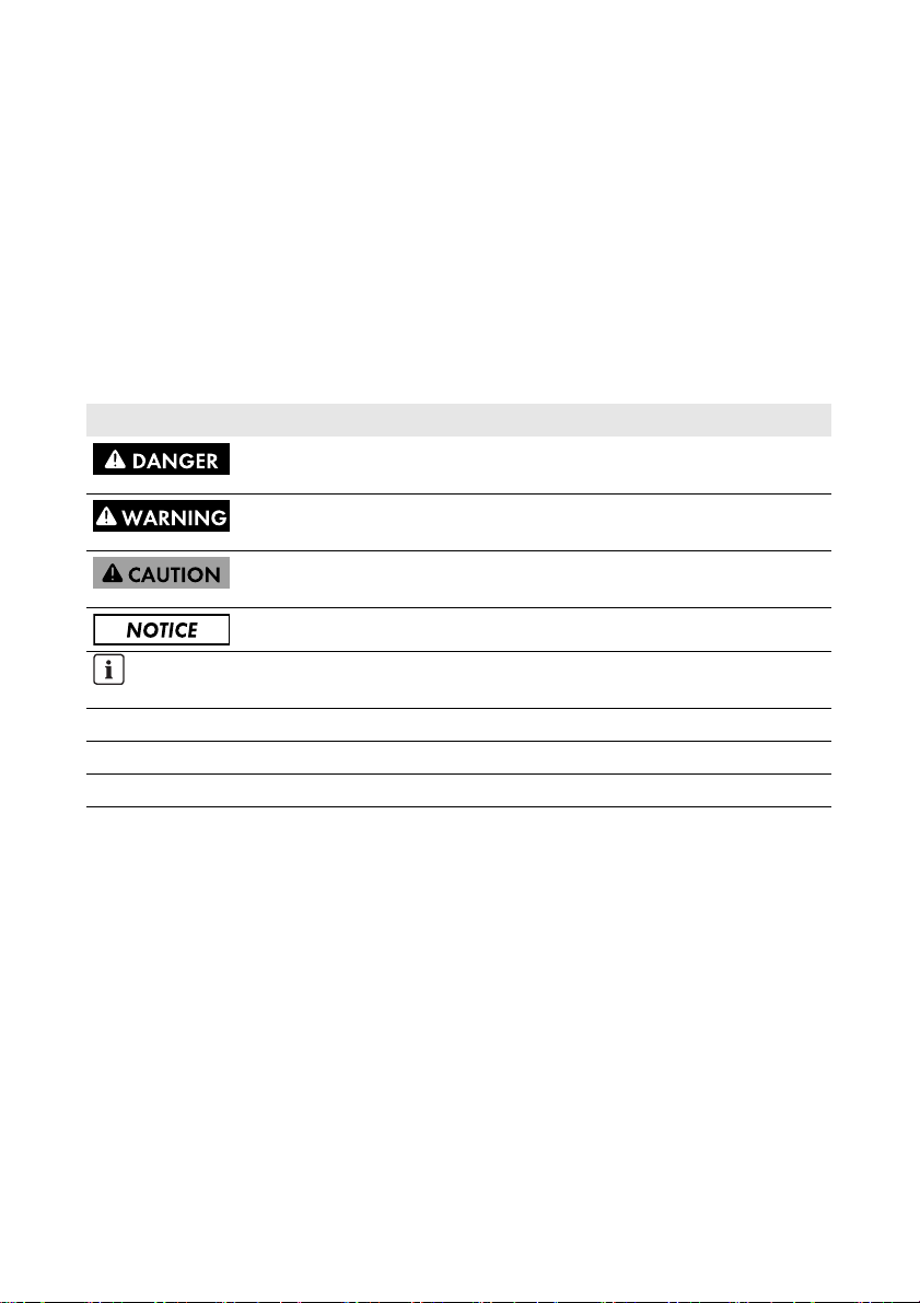
Symbols
Symbol Explanation
Indicates a hazardous situation which, if not avoided, will result in death
or serious injury
Indicates a hazardous situation which, if not avoided, could result in death
or serious injury
Indicates a hazardous situation which, if not avoided, could result in minor
or moderate injury
Indicates a situation which, if not avoided, could result in property damage
Information that is important for a specific topic or goal, but is not
safety-relevant
☐ Indicates an essential requirement for achieving a specific goal
☑ Desired result
✖ A problem that might occur
Installation Manual SPW-WebconPB-IA-en-11 5
Page 6

1 Information on this Document SMA Solar Technology AG
Typography
Typography Explanation Example
bold • Display messages
• Elements of a user interface
• Connections
• Elements to be selected
• Elements to be entered
> • Connects several elements
• The value can be read from the
Energy field.
• Select Settings.
•Enter the value 10 in the
Minutes field.
• Select Settings > Date.
that are to be selected
[Button/Key] • B utt on o r ke y to be s elec ted or
• Select [Next].
pressed
Nomenclature
Full designation Designation in this document
PV plant Plant
SMA Cluster Controller Cluster Controller
SMA Speedwire Speedwire
SMA Speedwire/Webconnect Piggy-Back Piggy-Back
SMA Webconnect function Webconnect function
SMA inverter Inverter
6 SPW-WebconPB-IA-en-11 Installation Manual
Page 7

SMA Solar Technology AG 2 Safety
2 Safety
2.1 Intended Use
The Speedwire/Webconnect Piggy-Back is a Speedwire communication interface with Webconnect
function for inverters.
Speedwire is a cable-based type of communication based on the Ethernet standard and the
communication protocol SMA Data2+. This enables inverter-optimised 10/100 Mbit data
transmission between Speedwire devices in PV plants.
The Webconnect function enables data transmission between a small plant and the Internet portal
Sunny Portal. In Sunny Portal, a maximum of four inverters can be combined in a Sunny Portal plant.
In Italy, the Speedwire/Webconnect Piggy-Back can be used for plants up to 6 kW that are
connected to the low-voltage grid. The Speedwire/Webconnect Piggy-Back implements grid
management for one inverter. The Speedwire/Webconnect Piggy-Back also receives specifications
fr om t he n etw ork ope rator vi a Et her net (in acc ord anc e with st andard CEI 0-21). The network operator
sends the control signals to the Speedwire/Webconnect Piggy-Back via a network operator gateway.
The Speedwire/Webconnect Piggy-Back fulfils the following tasks:
• Set-up of a Speedwire network in small and large-scale PV plants
• Data exchange with Sunny Portal:
– in small plants via a router with Internet connection
– in large-scale PV plants via the Cluster Controller
• Data exchange with Sunny Explorer
• Additionally for Italy:
– Implementation of grid management for one inverter
–Active power limitation of the connected active power
– Remote shutdown within 50 ms
– Narrowing of the frequency limits to between 49.5 Hz and 50.5 Hz
– Automatic narrowing of the inverter frequency limits to between 49.5 Hz and 50.5 Hz
when the connection to the network operator gateway is interrupted
The Speedwire/Webconnect Piggy-Back is available as a retrofit kit.
The inverter still complies with the standard after the product has been installed.
Installation Manual SPW-WebconPB-IA-en-11 7
Page 8

2 Safety SMA Solar Technology AG
The Speedwire/Webconnect Piggy-Back must only be operated with supported products
(see Section 2.2).
For safety reasons, it is not permitted to modify the product or install components that are not explicitly
recommended or distributed by SMA Solar Technology AG for this product.
The enclosed documentation is an integral part of this product.
• Read and observe the documentation.
• Keep the documentation in a convenient place for future reference.
Only use the Speedwire/Webconnect Piggy-Back in accordance with the information provided in the
enclosed documentation. Any other use may result in personal injury or property damage.
2.2 Supported Products
SMA inverter
The Speedwire/Webconnect Piggy-Back must only be used in the following inverters with at least the
given firmware version:
Sunny Boy / Sunny Mini Central From firmware version
SB 1300TL-10, SB 1600TL-10, SB 2100TL 4.30
SB 3300-11, SB 3800-11 4.02
SMC 6000A-11 4.33
SMC 7000HV-11 2.21
Firmware updates on the inverters can only be carried out by SMA Service. If your inverter is in need
of a firmware update, contact the SMA Service Line (see Section 10).
Additional SMA products
• Sunny Explorer from software version 1.05
Sunny Explorer is available free of charge at www.SMA-Solar.com.
• Cluster Controller
2.3 Qualifications of Skilled Persons
The work described in this document must be performed by skilled persons only. Skilled persons must
have the following qualifications:
• Training in the installation and commissioning of electrical devices and plants
• Knowledge of how to deal with the dangers and risks associated with installing and using
electrical devices and plants
• Knowledge of all applicable standards and directives
• Knowledge of how an inverter works and is operated
• Knowledge of and adherence to this document and all safety precautions
8 SPW-WebconPB-IA-en-11 Installation Manual
Page 9

SMA Solar Technology AG 2 Safety
2.4 Safety Precautions
Electric Shock
Lethal voltages are present in the conductive parts of the inverter.
• Prior to performing any work on the inverter, disconnect the inverter from any voltage sources
on the AC and DC sides (see inverter installation manual). Observe the waiting time to allow
the capacitors to discharge.
Burn Hazards
Some parts of the inverter enclosure can get hot during operation.
• During operation, touch the inverter on the enclosure lid only.
Environmental Influences
When close d and wi th the E SS plugged i n, the inverter has the degree of protection IP65. The inverter
is thus protected against dust intrusion and water penetration. Dust intrusion and water penetration
can damage the inverter.
• If the ESS is not plugged in, the inverter must be protected against dust and water.
• Firmly plug ESS in again after performing any work on the inverter.
2.5 Operating Information
Selecting a Suitable Internet Tariff for Small Plants
When using the new Webconnect function, a constant Internet connection is required.
De pen din g on the qu ali ty o f the Int ern et c onn ect ion , th e transm ission volume for an inverter is between
150 MB and 550 MB per month. When using the plant overview in Sunny Portal with live data
display, there is an additional data volume of 600 kB per hour.
• SMA recommends using an Internet tariff with a flat rate.
• Since Sunny Portal is permanently connected to the Internet, time-based billing systems should
be avoided. High costs could be incurred.
Installation Manual SPW-WebconPB-IA-en-11 9
Page 10
3 Scope of Delivery SMA Solar Technology AG
3 Scope of Delivery
Check the scope of delivery for completeness and any externally visible damage. Contact your
specialist dealer if the delivery is incomplete or damaged.
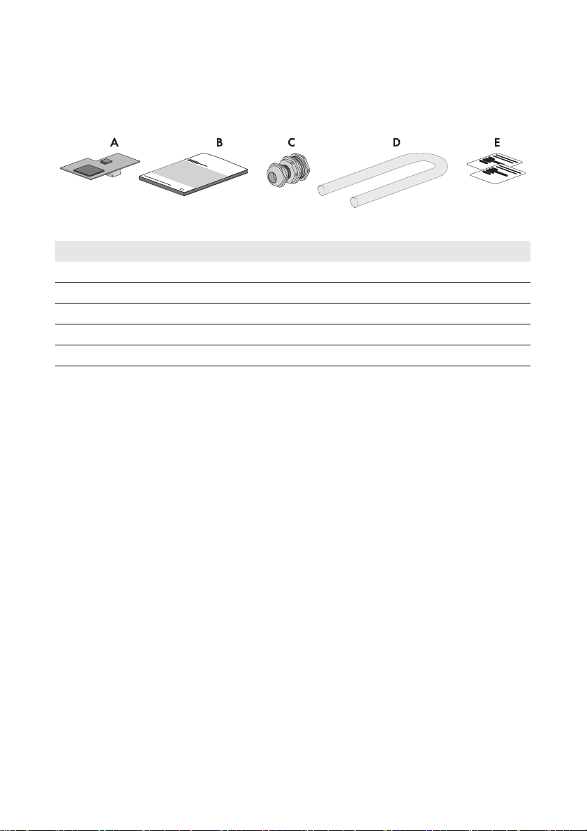
Figure1: Components included in the scope of delivery
Item Quantity Description
A 1 SMA Speedwire/Webconnect Piggy-Back (SWPB-10.BG1)
B 1 Installation manual
C 1 Cable gland
D1Silicone tube
E 2 Label with PIC and RID for registration in Sunny Portal
10 SPW-WebconPB-IA-en-11 Installation Manual
Page 11

SMA Solar Technology AG 4 Product Description
4 Product Description
4.1 SMA Speedwire/Webconnect Piggy-Back
The Speedwire/Webconnect Piggy-Back is a Speedwire communication interface with Webconnect
function for inverters.
Speedwire is a cable-based type of communication based on the Ethernet standard and the
communication protocol SMA Data2+. This enables inverter-optimised 10/100 Mbit data
transmission between Speedwire devices in PV plants.
The Webconnect function enables data transmission between a small plant and the Internet portal
Sunny Portal. In Sunny Portal, a maximum of four inverters can be combined in a Sunny Portal plant.
In Italy, the Speedwire/Webconnect Piggy-Back can be used for plants up to 6 kW that are
connected to the low-voltage grid. The Speedwire/Webconnect Piggy-Back implements grid
management for one inverter. The Speedwire/Webconnect Piggy-Back also receives specifications
fr om t he n etw ork ope rator vi a Et her net (in acc ord anc e with st andard CEI 0-21). The network operator
sends the control signals to the Speedwire/Webconnect Piggy-Back via a network operator gateway.
The Speedwire/Webconnect Piggy-Back fulfils the following tasks:
• Set-up of a Speedwire network in small and large-scale PV plants
• Data exchange in a large-scale PV plant with Cluster Controller via a router/network switch
• Data exchange with Sunny Portal:
– in small plants via a router with Internet connection
– in large-scale PV plants via the Cluster Controller
• Data exchange with Sunny Explorer
• Additionally for Italy:
– Implementation of grid management for one inverter
–Active power limitation of the connected active power
– Remote shutdown within 50 ms
– Narrowing of the frequency limits to between 49.5 Hz and 50.5 Hz
– Automatic narrowing of the inverter frequency limits to between 49.5 Hz and 50.5 Hz
when the connection to the network operator gateway is interrupted
The Speedwire/Webconnect Piggy-Back is available as a retrofit kit.
Installation Manual SPW-WebconPB-IA-en-11 11
Page 12

4 Product Description SMA Solar Technology AG
Figure2: Layout of the SMA Speedwire/Webconnect Piggy-Back
Item Description
A Female connector
Label with PIC and RID for Registration of a Small Plant in Sunny Portal
To activate the Piggy-Back in Sunny Portal, you will need the PIC and RID numbers printed on the
supplied label. After installation of the Piggy-Back, a label should be affixed on the exterior of the
inverter in the vicinity of the type label. Keep the other label in a safe place for future reference.
4.2 Possible Network Topologies
The possible network topologies depend on the devices used and on the number of network ports.
The Speedwire/Webconnect Piggy-Back is equipped with one network port. For further information
on network topologies, refer to the Technical Information "SMA Speedwire Fieldbus" at
www.SMA-Solar.com.
4.3 Type Label
Type Label
The type label clearly identifies the Speedwire/Webconnect Piggy-Back. The type label is located on
the front panel of the Speedwire/Webconnect Piggy-Back.
Figure3: Layout of the type label
Item Explanation
A Device type
B Serial number
C Hardware version
The information on the type label is required for safe use of the Speedwire/Webconnect Piggy-Back
and for reference if customer support from the SMA Service Line is needed. The type label must be
permanently affixed to the Speedwire/Webconnect Piggy-Back.
12 SPW-WebconPB-IA-en-11 Installation Manual
Page 13

SMA Solar Technology AG 4 Product Description
Supplementary Label with Data for Registration in Sunny Portal
The supplementary label is located on the front panel of the Speedwire/Webconnect Piggy-Back.
The data for registration in Sunny Portal is to be found on the supplementary labels supplied.
Figure4: Layout of the supplementary label
Item Explanation
A Identification key of the Piggy-Back for registration in Sunny Portal
B Registration ID of the Piggy-Back for registration in Sunny Portal
C MAC address of the Piggy-Back
Symbol on the Supplementary label
Symbol Description Explanation
CE marking The product complies with the
requirements of the applicable EU
directives.
4.4 Cable Gland
The cable gland provides a sturdy, tightly sealed connection of the network cables with the inverter
enclosure. The cable gland also protects the inverter from dust intrusion and moisture penetration.
Figure5: Product description: Cable gland
Item Description
ASwivel nut
B Adaptor PG16 to M16
CCounter nut
Installation Manual SPW-WebconPB-IA-en-11 13
Page 14

5 Connection SMA Solar Technology AG
5 Connection
5.1 Inverter Connection Area
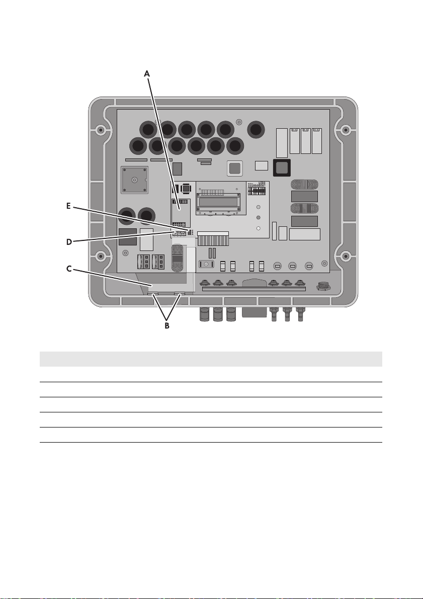
SB 1300TL-10, SB 1600TL-10, SB 2100TL
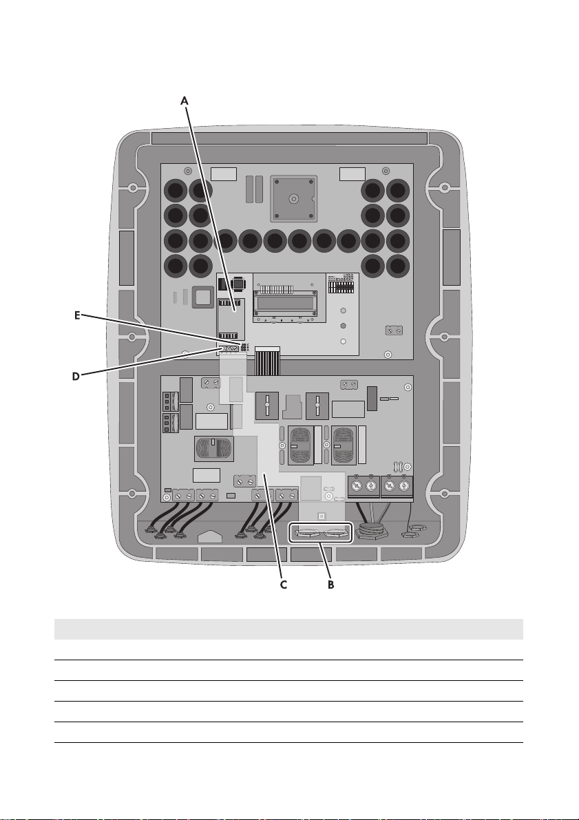
Figure6: Overview of the connection area
Item Description
A Slot for Piggy-Back
B Opening in the inverter enclosure with filler plug
C Cable route to communication terminal
D Communication terminal
E Jumper slot for communication
14 SPW-WebconPB-IA-en-11 Installation Manual
Page 15
SMA Solar Technology AG 5 Connection
SB 3300-11, SB 3800-11
Figure7: Overview of the connection area
Item Description
A Slot for Piggy-Back
B Opening in the inverter enclosure with filler plug
C Cable route to communication terminal
D Communication terminal
E Jumper slot for communication
Installation Manual SPW-WebconPB-IA-en-11 15
Page 16
5 Connection SMA Solar Technology AG
SMC 6000A-11, SMC 7000HV-11
Figure8: Overview of the connection area
Item Description
A Slot for Piggy-Back
B Opening in the inverter enclosure with filler plug
C Cable route to communication terminal
D Communication terminal
E Jumper slot for communication
16 SPW-WebconPB-IA-en-11 Installation Manual
Page 17

SMA Solar Technology AG 5 Connection
5.2 Cable Requirements and Information on Routing
The cable length and quality have an effect on the signal quality in the Speedwire network. Observe
the following information and cable requirements:
Disturbance of data transmission due to AC Cables
When AC cables are in operation, they generate an electromagnetic field which may induce
interference in network cables during data transmission.
• Lay the network cables using suitable fastening material and with a minimum clearance
of 50 mm to the AC cables.
Cable requirements
☐ Cable length between two nodes: max. 100 m
☐ Cross-section: at least 2x2x0.22 mm
☐ Cable type: 100BaseTx, CAT5 with shielding S-UTP, F-UTP or higher
☐ UV-resistant for outdoor use
☐Type of plug: RJ45
SMA Solar Technology AG recommends the following cable types:
• For outdoor use: SMA COMCAB-OUTxxx
• For indoor use: SMA COMCAB-INxxx
The cables are available in the lengths xxx = 100 m, 200 m, 500 m, 1,000 m
2
or at least 2x2 AWG 24
5.3 Connecting the Cable to the Communication Terminal
Figures in this section
The work steps in this section are supported by figures of the inverter types SB 3300-11 and
SB 3800-11. The procedure for other inverter types is analogous (see Section 5.1).
Requirement:
☐ For Italy: There must be an available network operator gateway with network connection for
telecontrol protocol IEC 61850.
Additionally required material (not included in the scope of delivery):
☐ 1 network cable (see Section 5.2)
☐ 4 bootlace ferrules
☐ 1 RJ45 connector
Installation Manual SPW-WebconPB-IA-en-11 17
Page 18
5 Connection SMA Solar Technology AG
Procedure:
1.
Danger to life due to electric shock when opening the inverter
Lethal voltages are present in the conductive parts of the inverter.
• Disconnect the inverter fro m any vo ltage sources on the AC and DC sides (see the inverter
installation manual). Observe the waiting time to allow the capacitors to discharge.
2. Open the inverter (see inverter installation manual).
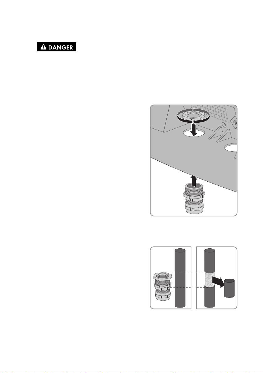
3. Push one filler plug from the inside out of the bottom of the inverter enclosure.
4. Attach the cable gland to the enclosure opening
using the counter nut. Ensure that the grooved side of
the counter nut is facing the inverter enclosure.
5. Gauge the length from the communication terminal to the counter nut on the cable gland using
the cable, and mark the position on the cable. Be sure to take the permitted cable route into
account (see Section 5.1).
6. Below the marked position, remove 20 mm from the
cable sheath. This will enable contact between the
screening clamp and the cable shield in the cable
gland.
7. Unscrew the swivel nut of the cable gland but do not remove it.
18 SPW-WebconPB-IA-en-11 Installation Manual
Page 19

SMA Solar Technology AG 5 Connection
8. Gradually guide the end of the cable through the
cable gland into the inverter, until you can hear the
screening clamp grip onto the cable shield.
9. Tighten the swivel nut of the cable gland. This will prevent the cable from slipping and the
contact between screening clamp and cable shield being lost.
10. At the end of the cable, remove 40 mm from the cable sheath and cable shield. Make sure that
no pieces of cable are dropped into the inverter.
11. At the end of the cable, strip the insulation of the four required wires by 6 mm. Take the type of
cable into account, as listed below:
Network cable
Signal EIA/TIA 568A (8-wire)
Wire colour
Profinet (4-wire)
Wire colour
TD+ white/green yellow
TD- green orange
RD+ white/orange white
RD- orange blue
12. Shorten all other wires flush with the cable sheath.
13. Attach the bootlace ferrules to the wire ends.
Installation Manual SPW-WebconPB-IA-en-11 19
Page 20
5 Connection SMA Solar Technology AG
14.
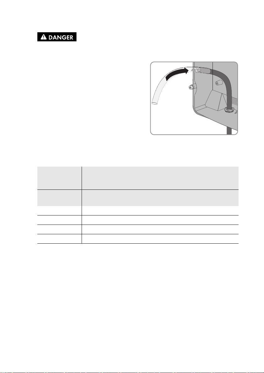
Danger to life due to electric shock in case of incorrect cable insulation
If a cable is not correctly insulated, high voltages may occur on the cable outside the inverter.
• Lead the cable into the inverter through the
silicone t ube. Th e silicone tube mu st complete ly
cover the cable and the wires inside the inverter
enclosure.
• Cut the silicone tube to the required length, as
necessary.
• Fix the silicone tube in position with cable ties
at the beginning and end of the cable, as
necessary. Trim the ends of the cable ties. This
will prevent the ends of the cable ties causing
damage to hot components in the inverter.
15. Connect the wire ends to the communication terminal in the inverter at screw terminals 2, 3, 5
and 7 (torque: 0.23 Nm) (for position of the communication terminal, see Section 5.1).
Observe the permitted cable route (see Section 5.1) and the pin assignment as follows:
Inverter
Network cable
communication
terminal
Pin Signal EIA/TIA 568A (8-wire)
Wire colour
Profinet (4-wire)
Wire colour
2 TD+ white/green yellow
3 TD- green orange
7 RD+ white/orange white
5RD-orange blue
16. Make sure that there are no jumpers in the communication jumper slot (position of jumper slot
for communication, see Section 5.1).
20 SPW-WebconPB-IA-en-11 Installation Manual
Page 21
SMA Solar Technology AG 5 Connection
17. Attach an RJ45 connector to the other end of the cable (see manufacturer's manual). Observe
the pin assignment of the network cable, as follows:
Network cable
Signal Pin RJ45 plug EIA/TIA 568A (8-wire)
Wire colour
Profinet (4-wire)
Wire colour
TD+ 1 white/green yellow
TD- 2 green orange
RD+ 3 white/orange white
RD- 6 orange blue
18. Subject to the required network topology, connect the other end of the cable to a router,
network switch or Cluster Controller (see manual of the respective device). To do this, a router
with Internet connection must be connected to the plant.
5.4 Installing the Piggy-Back
1.
Danger to life due to electric shock when opening the inverter
Lethal voltages are present in the conductive parts of the inverter.
• If the inverter is closed, proceed as follows:
• Disconnect the inverter from any voltage sources on the AC and DC sides (see the
inverter installation manual). Observe the waiting time to allow the capacitors to
discharge.
• Open the inverter (see inverter installation manual).
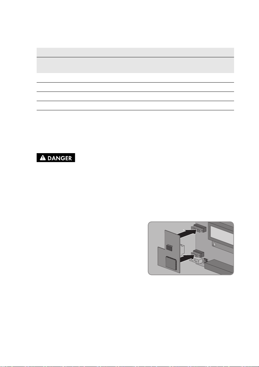
2. Plug the Piggy-Back into the female connectors at
the slot in the inverter (for position of slot, see
Section 5.1).
3. Stick one of the labels with the data for registration in Sunny Portal (PIC and RID) on the outside
of the inverter in the vicinity of the type label.
4. Close the inverter (see inverter installation manual).
Installation Manual SPW-WebconPB-IA-en-11 21
Page 22

6 Commissioning SMA Solar Technology AG
6 Commissioning
6.1 Commissioning a Large-Scale PV Plant with Cluster Controller
Requirements:
☐ The cable must be connected to the communication terminal (see Section 5.3).
☐ The Piggy-Back must be installed in the inverter (see Section 5.4).
☐ Subject to the required network topology, the Cluster Controller must be connected to the
Speedwire network (see Cluster Controller installation manual).
Procedure:
1. Commission all inverters with installed Piggy-Back (see inverter installation manual).
2.
Deactivating the Webconnect function of the inverters
In a large-scale PV plant with Cluster Controller, communication with Sunny Portal takes
place via the Cluster Controller itself.
For optimal operation of large-scale PV plants with Cluster Controller, deactivate the
factory-activated Webconnect function of the inverter with installed Piggy-Back
(see Cluster Controller user manual).
6.2 Commissioning a Small Plant
Requirements:
☐ The cable must be connected to the communication terminal (see Section 5.3).
☐ The Piggy-Back must be installed in the inverter (see Section 5.4).
☐ The plant must be connected to a router with Internet connection.
☐ DHCP must be enabled for the router.
☐ For Italy, in order to adjust the Sunny Explorer settings for receiving control signals from the
Piggy-Back, you must have a personal SMA Grid Guard code (see Sunny Explorer help).
Procedure:
1. Commission all inverters with installed Piggy-Back (see inverter installation manual).
2. For plants in Italy, in order to adjust the settings to receive control signals from the network
operator in the Piggy-Back, follow the steps below:
• Connect to Sunny Explorer (see Section 6.3.2).
• Enter your personal SMA Grid Guard code in Sunny Explorer (see Sunny Explorer help).
22 SPW-WebconPB-IA-en-11 Installation Manual
Page 23

SMA Solar Technology AG 6 Commissioning
• Set the following parameters in Sunny Explorer (for setting parameters in a device, see
Sunny Explorer help):
External Communication > IEC 61850 configuration
Parameter Value/Range Resolution Default
Application-ID 0 to 0x4000 1 0x4000
Goose-Mac address 01:0C:CD:01:00:00
…
01:0C:CD:01:02:00
•In the field Application-ID, enter the Application-ID of the network operator gateway.
You will receive this value from your network operator. You can enter a value between
0 and 16384. The value 16384 indicates deactivation.
•In the field Goose-Mac address, enter the MAC address of the network operator
gateway from which the Piggy-Back is to receive control commands. You will receive this
value from your network operator. If all MAC addresses are to be accepted in the
adjustable domain, enter 01:0C:CD:01:02:00.
1 01:0C:CD:01:02:00
6.3 Managing Small Plants with Sunny Explorer
6.3.1 Functions and Parameter Settings in Sunny Explorer
The following functions for plant management in Sunny Explorer are available:
• Overview of the plant status
• Graphic display of key plant data, device data and energy values
• Parameterisation of individual devices or an entire device class
• Simple diagnostics thanks to the display of faults and events
• Data export of inverter energy values and events in CSV format
• Piggy-Back update
You can change the following parameters in Sunny Explorer:
• Device name of the inverter
• Automatic IP configuration On/Off
• DNS-IP, gateway IP, IP address, subnet mask
• Webconnect function On/Off
• IEC 61850 configuration for plants in Italy up to 6 kW
Installation Manual SPW-WebconPB-IA-en-11 23
Page 24

6 Commissioning SMA Solar Technology AG
6.3.2 Connecting to Sunny Explorer
Requirements:
☐ The plant must be commissioned (see Section 6.2).
☐ The inverter with Piggy-Back must be in feed-in operation.
Procedure:
1. Connect the computer to the router/network switch with a network cable.
2. Start Sunny Explorer and create a plant (see Sunny Explorer help).
6.4 Plant Registration in Sunny Portal
6.4.1 Registering a Small Plant in Sunny Portal
Requirements:
☐ The small plant must be commissioned (see Section 6.2).
☐ The inverter with Piggy-Back must be in feed-in operation.
☐ The pla nt m ust be c onn ecte d to a ro ute r wi th p erma nen t In ter net connection (see router manual).
☐ PIC and RID must be available for the Piggy-Back.
☐ Your computer must have an Internet connection.
☐ JavaScript must be activated in the Internet browser.
Maximum permissible number of devices for a small plant in Sunny Portal
In Sunny Portal you can manage several plants. A maximum of four inverters with integrated
Piggy-Back is permissible per small plant.
Small plant with Piggy-Back cannot be combined with other plants
If you have already registered a plant in Sunny Portal with another communication device,
e.g. Sunny WebBox, you will still need to create a separate small plant with Piggy-Back. It is not
possible to combine the Piggy-Back and other communication devices within one plant in
Sunny Portal. Sunny Portal treats the existing plant and the new small plant with Piggy-Back as
separate plants.
• Create a new small plant with Piggy-Back.
Starting the Plant Setup Assistant in Sunny Portal
The Plant Setup Assistant is a step-by-step guide of the processes required for user registration and the
registration of your plant in Sunny Portal.
1. Open www.SunnyPortal.com.
2. Select [Plant Setup Assistant].
☑ The Plant Setup Assistant opens.
3. Follow the instructions of the Plant Setup Assistant.
24 SPW-WebconPB-IA-en-11 Installation Manual
Page 25

SMA Solar Technology AG 6 Commissioning
6.4.2 Registering a Large-Scale PV Plant with Cluster Controller in Sunny Portal
Requirements:
☐ The large-scale PV plant with Cluster Controller must be commissioned (see Section 6.1).
☐ The inverter with Piggy-Back must be in feed-in operation.
☐ The Cluster Controller must be connected to a router with Internet connection
(see Cluster Controller installation manual).
☐ Your computer must have an Internet connection.
☐ JavaScript must be activated in the Internet browser.
Procedure:
• For large-scale PV plants with Cluster Controller, register in Sunny Portal using the
Cluster Controller user interface (see Cluster Controller user manual).
Installation Manual SPW-WebconPB-IA-en-11 25
Page 26

7 Decommissioning SMA Solar Technology AG
7 Decommissioning
7.1 Removing the Piggy-Back
1.
Danger to life due to electric shock when opening the inverter
Lethal voltages are present in the conductive parts of the inverter.
• Disconnect the inverter fro m any vo ltage sources on the AC and DC sides (see the inverter
installation manual). Observe the waiting time to allow the capacitors to discharge.
2. Open the inverter (see inverter installation manual).
3. Remove the Piggy-Back from the communication
interface.
4. Release the screw terminals at the communication terminal in the inverter and remove the wires.
5. Remove the silicone tube from the cable.
6. Unscrew the swivel nut of the cable gland.
7. Pull the cable out of the inverter.
8. Unscrew the counter nut of the cable gland and remove the cable gland.
9. Seal the enclosure opening of the inverter with the corresponding filler plug.
10. Close the inverter (see inverter installation manual).
7.2 Disposing of the Piggy-Back
• Dispose of the Piggy-Back in accordance with the regulations for the disposal of electronic
waste applicable at the installation site.
26 SPW-WebconPB-IA-en-11 Installation Manual
Page 27

SMA Solar Technology AG 8 Troubleshooting
8 Troubleshooting
8.1 General Errors
Problem Cause and corrective measures
The inverter with Piggy-Back
cannot be accessed.
Piggy-Back update does not
initialise.
There is no Speedwire connection.
Corrective measures:
• Ensure that all network cable plugs are inserted and locked.
• Ensure that all inverters in the plant are in operation.
• Ensure that the plant router is switched on.
• Ensure that the Piggy-Back is connected correctly
(see Section 5.3).
• Ensure that the Cluster Controller is connected to the local
plant network (see Cluster Controller installation manual).
The firmware version of the inverter is not supported
(see Section 2.2).
Corrective measures:
• An inverter firmware update can only be carried out by
SMA Service. If your inverter is in need of a firmware
update, contact the SMA Service Line (see Section 10).
The software version of Sunny Explorer is older than version 1.05.
Corrective measures:
• Download Sunny Explorer from software version 1.05 from
www.SMA-Solar.com and install.
Firewall or IP filter settings are not correct.
Corrective measures:
• Adjust the firewall or IP filter settings (see firewall or router
manual).
The Piggy-Back does not have a valid IP address.
Corrective measures:
• Make sure DHCP is enabled for the router.
Inverters with retrofitted Piggy-Back shut down overnight. It is
therefore not possible to establish any connection to these
inverters.
As soon as the inverters switch on in the morning, they will be
accessible again.
The feed-in power of the inverter is less than 50 W.
Corrective measures:
• Carry out update once the feed-in power of the inverter is at
least 50 W.
Installation Manual SPW-WebconPB-IA-en-11 27
Page 28

8 Troubleshooting SMA Solar Technology AG
8.2 Performing a Piggy-Back Update
Piggy-Back updates are performed via Sunny Explorer. There is no need to replace the Piggy-Back.
Existing inverter settings and data are retained after the update. Only carry out an update providing
that the feed-in power of the inverter is sufficient (at least 50 W). After a successful update, restart
Sunny Explorer.
28 SPW-WebconPB-IA-en-11 Installation Manual
Page 29

SMA Solar Technology AG 9 Technical Data
9 Technical Data
General Data
Mounting location in the inverter
Voltage supply via the inverter
Mechanical Data
Width x height x depth 50 mm x 81 mm x 12 mm
Communication
Communication interface Speedwire/Webconnect
Maximum cable length 100 m
Ambient Conditions for Storage/Transport
Ambient temperature − 40°C to +70°C
Relative humidity, non-condensing 5% to 95%
Maximum height above sea level (MSL) 3,000 m
Installation Manual SPW-WebconPB-IA-en-11 29
Page 30

10 Contact SMA Solar Technology AG
10 Contact
If you have technical problems concerning our products, contact the SMA Service Line. We require
the following information in order to provide you with the necessary assistance:
• Type, serial number and firmware version of the inverter
• Type, serial number and firmware version of the Piggy-Back
• For large-scale PV plants: serial number and firmware version of the Cluster Controller
• For small plants: PIC and RID of the Piggy-Back
Australia SMA Australia Pty Ltd.
Sydney
Belgien/
Belgique/
België
Brasil Vide España (Espanha)
Česko SMA Central & Eastern Europe
Chile Ver España
Danmark Se Deutschland (Tyskland)
Deutschland SMA Solar Technology AG
España SMA Ibérica Tecnología Solar,
France SMA France S.A.S.
SMA Benelux BVBA/SPRL
Mechelen
s.r.o.
Praha
Niestetal
S.L.U.
Barcelona
Lyon
Toll free for
Australia:
International: +61 2 9491 4200
+32 15 286 730
+420 235 010 417
Medium Power Solutions
Wechselrichter:
Kommunikation:
SMA Online Service Center:
www.SMA.de/Service
Hybrid Energy Solutions
Sunny Island: +49 561 9522-399
PV-Diesel
Hybridsysteme:
Power Plant Solutions
Sunny Central: +49 561 9522-299
Llamada gratuita en
España:
Internacional: +34 902 14 24 24
Medium Power Solutions
Onduleurs :
Communication :
Hybrid Energy Solutions
Sunny Island : +33 472 09 04 42
Power Plant Solutions
Sunny Central : +33 472 09 04 43
1800 SMA AUS
(1800 762 287)
+49 561 9522-1499
+49 561 9522-2499
+49 561 9522-3199
900 14 22 22
+33 472 09 04 40
+33 472 09 04 41
30 SPW-WebconPB-IA-en-11 Installation Manual
Page 31

SMA Solar Technology AG 10 Contact
India SMA Solar India Pvt. Ltd.
Mumbai
Italia SMA Italia S.r.l.
Milano
Κύπρος/
Kıbrıs
Luxemburg/
Luxembourg
Magyarország lásd Česko (Csehország)
Nederland zie Belgien (België)
Österreich Siehe Deutschland
Perú Ver España
Polska Patrz Česko (Czechy)
Portugal SMA Solar Technology Portugal,
România Vezi Česko (Cehia)
Schweiz Siehe Deutschland
Slovensko pozri Česko (Česká republika)
South Africa SMA Solar Technology
United
Kingdom
Ελλάδα SMA Hellas AE
България Вижте Ελλάδα (Гърция)
Βλέπε Ελλάδα/
Bkz. Ελλάδα (Yunanistan)
Siehe Belgien
Voir Belgique
Unipessoal Lda
Lisboa
South Africa Pty Ltd.
Centurion (Pretoria)
SMA Solar UK Ltd.
Milton Keynes
Αθήνα
SMA Solar (Thailand) Co., Ltd. +66 2 670 6999
+91 22 61713888
+39 02 8934-7299
Gratuito em
Portugal:
Internacional: +351 2 12 37 78 60
08600 SUNNY
(08600 78669)
International: +27 (12) 643 1785
+44 1908 304899
801 222 9 222
International: +30 212 222 9 222
800 20 89 87
대한민국 SMA Technology Korea Co., Ltd.서울+82 2 508-8599
+971 2 234-6177 SMA Middle East LLC
!
Other
countries
Installation Manual SPW-WebconPB-IA-en-11 31
International SMA Service Line
Niestetal
Toll free worldwide: 00800 SMA SERVICE
(+800 762 7378423)
Page 32

SMA Solar Technology
www.SMA-Solar.com
 Loading...