

Page 1
EN
Accessories for Central Inverter
SUNNY MAIN BOX / SUNNY MAIN BOX CABINET
Installation Manual
SMB-IA-en-10 | 98-4031510 | Version 1.0
Page 2

Page 3

SMA Solar Technology AG Table of Contents
Table of Contents
1 Information on this Document. . . . . . . . . . . . . . . . . . . . . . . 5
2 Safety . . . . . . . . . . . . . . . . . . . . . . . . . . . . . . . . . . . . . . . . . . 7
2.1 Intended Use. . . . . . . . . . . . . . . . . . . . . . . . . . . . . . . . . . . . . . . . 7
2.2 Qualification of Skilled Persons . . . . . . . . . . . . . . . . . . . . . . . . . 8
2.3 Safety Precautions. . . . . . . . . . . . . . . . . . . . . . . . . . . . . . . . . . . . 8
3 Scope of Delivery. . . . . . . . . . . . . . . . . . . . . . . . . . . . . . . . 10
3.1 Sunny Main Box . . . . . . . . . . . . . . . . . . . . . . . . . . . . . . . . . . . . 10
3.2 Sunny Main Box Cabinet . . . . . . . . . . . . . . . . . . . . . . . . . . . . . 11
4 Product Description . . . . . . . . . . . . . . . . . . . . . . . . . . . . . . 12
4.1 Sunny Main Box . . . . . . . . . . . . . . . . . . . . . . . . . . . . . . . . . . . . 12
4.2 Sunny Main Box Cabinet . . . . . . . . . . . . . . . . . . . . . . . . . . . . . 13
4.3 Type Label . . . . . . . . . . . . . . . . . . . . . . . . . . . . . . . . . . . . . . . . 14
5 Assembly. . . . . . . . . . . . . . . . . . . . . . . . . . . . . . . . . . . . . . . 16
5.1 Mounting the Sunny Main Box. . . . . . . . . . . . . . . . . . . . . . . . . 16
5.1.1 Selecting the Mounting Location. . . . . . . . . . . . . . . . . . . . . . . . . . . . . . . . . . 16
5.1.2 Mounting the Sunny Main Box on a Wall . . . . . . . . . . . . . . . . . . . . . . . . . . 16
5.2 Mounting the Sunny Main Box Cabinet . . . . . . . . . . . . . . . . . . 18
5.2.1 Selecting the Mounting Location. . . . . . . . . . . . . . . . . . . . . . . . . . . . . . . . . . 18
5.2.2 Mounting the Base . . . . . . . . . . . . . . . . . . . . . . . . . . . . . . . . . . . . . . . . . . . . 18
5.2.3 Mounting the Sunny Main Box Cabinet on the Base . . . . . . . . . . . . . . . . . . 19
6 Electrical Connection . . . . . . . . . . . . . . . . . . . . . . . . . . . . . 20
6.1 Overview of the Connection Area . . . . . . . . . . . . . . . . . . . . . . 20
6.1.1 Sunny Main Box . . . . . . . . . . . . . . . . . . . . . . . . . . . . . . . . . . . . . . . . . . . . . . 20
6.1.2 Sunny Main Box Cabinet . . . . . . . . . . . . . . . . . . . . . . . . . . . . . . . . . . . . . . . 21
6.2 Connecting the String Cables to the Fuse Holders . . . . . . . . . . 23
6.3 Connecting the DC Input Cables . . . . . . . . . . . . . . . . . . . . . . . 24
Installation Manual SMB-IA-en-10 3
Page 4

Table of Contents SMA Solar Technology AG
6.4 Connecting the Earth Cable . . . . . . . . . . . . . . . . . . . . . . . . . . . 24
7 Requirements for Commissioning . . . . . . . . . . . . . . . . . . . 25
8 Disconnecting the Sunny Main Box or
Sunny Main Box Cabinet. . . . . . . . . . . . . . . . . . . . . . . . . . 26
9 Decommissioning . . . . . . . . . . . . . . . . . . . . . . . . . . . . . . . . 28
9.1 Dismantling Sunny Main Box and Sunny Main Box Cabinet . . 28
9.2 Disposing of Sunny Main Box and Sunny Main Box Cabinet . 28
10 Technical Data . . . . . . . . . . . . . . . . . . . . . . . . . . . . . . . . . . 29
11 Contact . . . . . . . . . . . . . . . . . . . . . . . . . . . . . . . . . . . . . . . . 34
4 SMB-IA-en-10 Installation Manual
Page 5
SMA Solar Technology AG 1 Information on this Document
%"/(&3
8"3/*/(
$"65*0/
/05*$&
1 Information on this Document
Validity
This document is valid for the following device types:
•SMB
•SMB-C
Target Group
This document is intended for skilled persons. Only persons with appropriate skills are allowed to
perform the tasks set forth in this document (see Section 2.2"Qualification of Skilled
Persons",page8).
Additional Information
Links to additional information can be found at www.SMA-Solar.com:
Document title Document type
Sunny Main Box - Connection of DC cabling for PV inverters Technical Information
Sunny Main Box Cabinet - Connection of DC cabling for PV inverters Technical Information
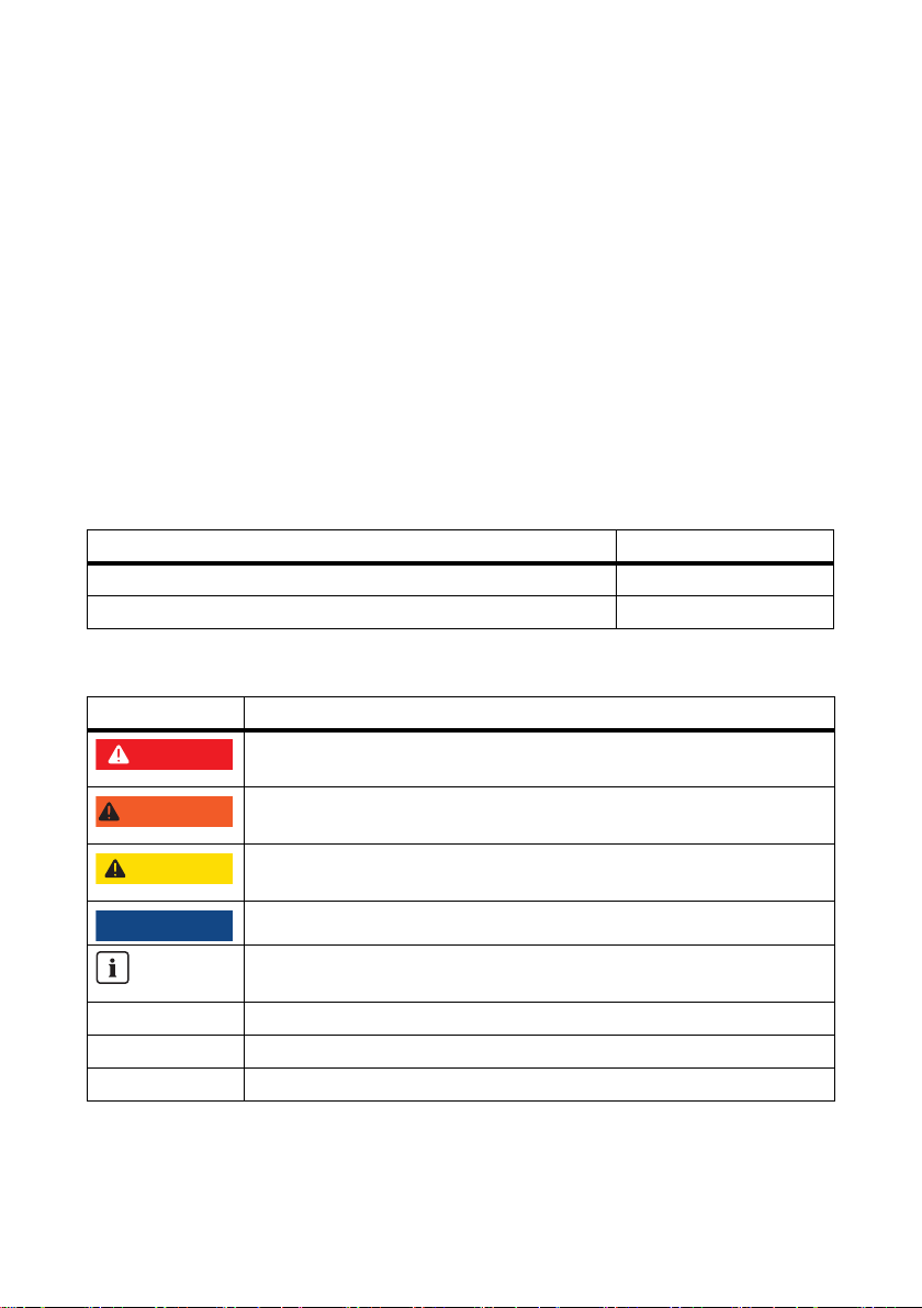
Symbols
Symbol Explanation
Indicates a hazardous situation which, if not avoided, will result in death or
serious injury
Indicates a hazardous situation which, if not avoided, could result in death or
serious injury
Indicates a hazardous situation which, if not avoided, could result in minor or
moderate injury
Indicates a situation which, if not avoided, could result in property damage
Information that is important for a specific topic or goal, but is not
safety-relevant
☐ Indicates an essential requirement for achieving a specific goal
☑ Desired result
✖ A problem that might occur
Installation Manual SMB-IA-en-10 5
Page 6

1 Information on this Document SMA Solar Technology AG
Abbreviations
Abbreviation Designation Explanation
AC Alternating Current ‒
DC Direct Current ‒
LV/HRC Low-Voltage, High Rupturing Capacity ‒
PV Photovoltaics ‒
6 SMB-IA-en-10 Installation Manual
Page 7
SMA Solar Technology AG 2 Safety
2Safety
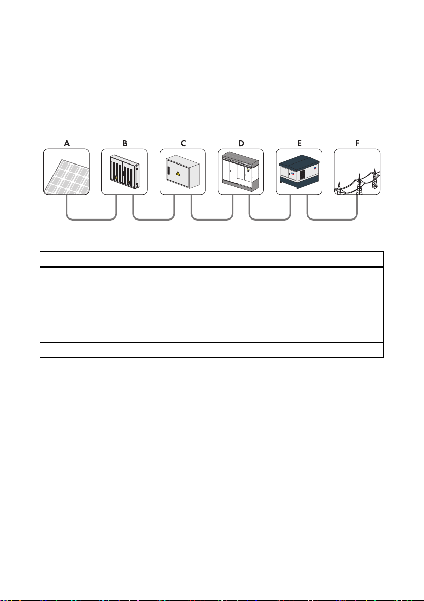
2.1 Intended Use
The Sunny Main Box and the Sunny Main Box Cabinet are DC main distributions which gather the
outgoing string cables from the DC sub-distributions and lead them to the central inverter via the
DC main cable.
Figure1: Overview of a PV plant with Sunny Main Boxes and a central inverter
Position Designation
APV modules
B DC sub-distribution (e.g. Sunny String-Monitor)
C DC main distribution, e.g., Sunny Main Box
D Central inverter
E Transformer station, z. B. Transformer Compact Station
F Electricity grid
For optimum operation of the Sunny Main Box or Sunny Main Box Cabinet, observe the requirements
for the mounting location. For safety reasons, it is not permitted to modify the product or install
components that are not explicitly recommended or distributed by SMA Solar Technology AG for this
product.
The enclosed documentation is an integral part of this product.
• Read and observe the documentation.
• Keep the documentation in a convenient place for future reference.
Only use the Sunny Main Box and Sunny Main Box Cabinet in accordance with the information
provided in the enclosed documentation. Any other use may result in personal injury or property
damage.
Installation Manual SMB-IA-en-10 7
Page 8

2 Safety SMA Solar Technology AG
2.2 Qualification of Skilled Persons
The work described in this document must be performed by skilled persons only. Skilled persons must
have the following qualifications:
• Knowledge of how the device works and is operated
• Training in how to deal with the dangers and risks associated with installing and using electrical
devices
• Training in the installation and commissioning of electrical devices
• Knowledge of all applicable standards and directives
• Knowledge of and compliance with this document and all the safety precautions
2.3 Safety Precautions
Electric Shock
High voltages capable of causing electric shocks are present in the Sunny Main Box and
Sunny Main Box Cabinet. Therefore, work on the Sunny Main Box and Sunny Main Box Cabinet is
permitted only with the power disconnected and in compliance with the guidelines applicable at the
installation location.
• Disconnecting the device:
– If there is a DC power switch in the upstream DC sub-distributions, switch it off.
– Only re move t he DC f uses o n the c entra l inverter once the inverter is disconnected and using
the LV/HRC fuse handle.
– If the central inverter is equipped with the "Optiprotect" option, switch the miniature circuit-
breakers in the central inverter off.
– Only pull out the DC fuse in the Sunny Main Box or Sunny Main Box Cabinet once the
inverter is disconnected and using the LV/HRC fuse handle.
• Ensure that the device cannot be reconnected.
• Check that no voltage is present.
• Earth and short-circuit.
• Cover or shield any adjacent live components. Protective covers must always be in place.
In the event of an earth fault, remember that plant components which are presumed earthed may still
be live.
• Ensure that no voltage is present before touching any plant components.
8 SMB-IA-en-10 Installation Manual
Page 9

SMA Solar Technology AG 2 Safety
If the Sunny Main Box or Sunny Main Box Cabinet is operated in a damaged condition, there is a
risk of serious injury by electric shock.
• Only use the Sunny Main Box or Sunny Main Box Cabinet when it is in perfect working order
and can be operated safely.
• Regularly check the Sunny Main Box or Sunny Main Box Cabinet for visible damage.
• Ensure that all external safety equipment is freely accessible at all times and that regular checks
are carried out to ensure that it is fully functional.
Burn Hazards
Some device components such as fuses can get hot during operation.
• Wear safety gloves when working on the device.
Damage to the Sunny Main Box or Sunny Main Box Cabinet
If unauthorised persons interfere with the Sunny Main Box, Sunny Main Box Cabinet or PV plant, the
equipment could be damaged.
• Lock the devices once they have been put into operation.
• Remove the keys from the door locks.
• Store the keys in a safe place.
When closed, the Sunny Main Box and Sunny Main Box Cabinet correspond to International
Pr ote cti on R ati ng 5 4 an d ar e th us p rot ect ed f rom int rus ion of d ust and water. Penetrating moisture can
damage the Sunny Main Box or Sunny Main Box Cabinet.
• Do not perform any installation work in rainy or foggy conditions, or wh en hum idity is ove r 95%.
• After completion of work on the Sunny Main Box or Sunny Main Box Cabinet, lock the doors
again.
Installation Manual SMB-IA-en-10 9
Page 10
3 Scope of Delivery SMA Solar Technology AG
3Scope of Delivery
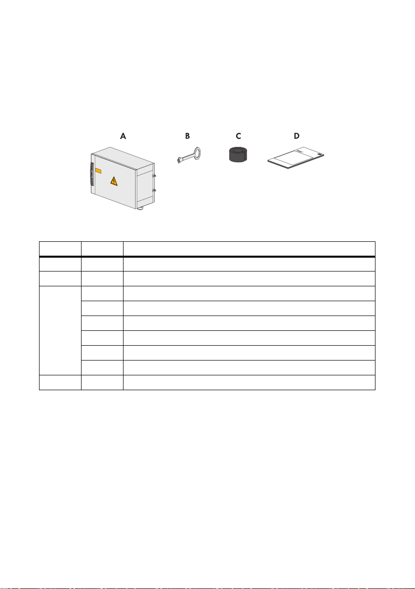
3.1 Sunny Main Box
Check the scope of delivery for completeness and any externally visible damage. Contact your
specialist dealer if the delivery is incomplete or damaged.
Figure2: Components included in scope of delivery
Position Quantity Designation
A 1 Sunny Main Box
B 1 Switch cabinet key
C 8 Seal insert 7.0 mm … 20.5 mm
8 Seal insert 17.0 mm … 20.5 mm
16 Seal insert 20 mm … 25 mm
16 Seal insert 24 mm … 28 mm
8 Seal insert 29 mm … 34 mm
8 Seal insert 32 mm … 36 mm
D 1 Installation manual
10 SMB-IA-en-10 Installation Manual
Page 11
SMA Solar Technology AG 3 Scope of Delivery
3.2 Sunny Main Box Cabinet
Check the scope of delivery for completeness and any externally visible damage. Contact your
specialist dealer if the delivery is incomplete or damaged.
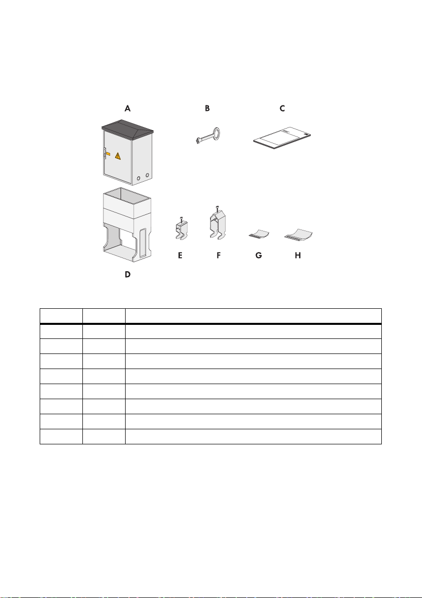
Figure3: Components included in scope of delivery
Position Quantity Designation
A 1 Sunny Main Box Cabinet
B 1 Switch cabinet key
C 1 Installation manual
D1Base
E 25 Cable clamp 22 mm … 28 mm
F 9 Cable clamp 28 mm … 34 mm
G 25 Bottom saddle for cable clamp 22 mm … 28 mm
H9Bottom saddle for cable clamp 28 mm … 34 mm
Installation Manual SMB-IA-en-10 11
Page 12

4 Product Description SMA Solar Technology AG
4 Product Description
4.1 Sunny Main Box
The Sunny Main Box is a DC main distribution which gathers the outgoing string cables from the
DC sub-distributions and leads them to the central inverter via the DC main cable.
Figure4: Components of the Sunny Main Box
Position Designation
A Switch cabinet lock
B Door
The Sunny Main Box is standardly equipped with 8 inputs. The Sunny Main Box is mounted on the
wall.
12 SMB-IA-en-10 Installation Manual
Page 13

SMA Solar Technology AG 4 Product Description
4.2 Sunny Main Box Cabinet
The Sunny Main Box Cabinet is a DC main distribution which gathers the outgoing string cables from
the DC sub-distributions and leads them to the central inverter via the DC main cable.
Figure5: Components of the Sunny Main Box Cabinet
Position Designation
A Switch cabinet lock
B Door
Depending on the version, the Sunny Main Box Cabinet is equipped with 2 x 8, 2 x 2 x 4 or 2 x 2 x 3
inputs. The Sunny Main Box Cabinet is mounted on a base and is equipped with a door on both front and
rear sides.
Installation Manual SMB-IA-en-10 13
Page 14

4 Product Description SMA Solar Technology AG
4.3 Type Label
The type label provides clear identification of the Sunny Main Box or Sunny Main Box Cabinet. The
Sunny Main Box and Sunny Main Box Cabinet are each fitted with 1 type label. The type label is
located on the inside of the door.
Figure6: Layout of the type label (example)
Position Designation Explanation
A Type Device type and option code
B Serial No. Serial number of the Sunny Main Box or
Sunny Main Box Cabinet
C ‒ Device-specific characteristics
You will need the information on the type label to ensure safe use of the Sunny Main Box or
Sunny Main Box Cabinet and when seeking customer support from the SMA Service Line.
The type label must be permanently affixed to the Sunny Main Box or Sunny Main Box Cabinet.
14 SMB-IA-en-10 Installation Manual
Page 15
SMA Solar Technology AG 4 Product Description
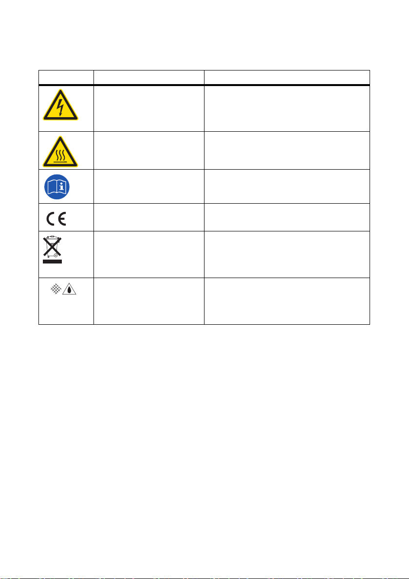
Symbols on the Type Label
Symbol Designation Explanation
Danger to life due to high
voltages
High voltages are present in the device. All work
on the Sunny Main Box or Sunny Main Box
Cabinet must be carried out by electrically skilled
persons only.
Risk of burns from hot surfaces The product can get hot during operation. Avoid
contact during operation. Wear your safety
gloves.
Observe the documentation. Observe all documentation that is supplied with
the product.
CE marking The product complies with the requirements of
the applicable EC directives.
WEEE designation Do not dispose of the product together with the
household waste but only in accordance with the
locally applicable regulations for disposal of
electronic waste.
Degree of protection IP54 The product is protected against dust and water
penetration. The Sunny Main Box and Sunny
Main Box Cabinet are suitable for outdoor
installation.
Installation Manual SMB-IA-en-10 15
Page 16
5 Assembly SMA Solar Technology AG
%"/(&3
$"65*0/
/05*$&
5Assembly
5.1 Mounting the Sunny Main Box
5.1.1 Selecting the Mounting Location
Danger to life due to fire or explosion
• Do not mount the Sunny Main Box on flammable construction materials.
• Do not mount the Sunny Main Box in areas containing highly flammable materials.
• Do not mount the Sunny Main Box in potentially explosive atmospheres.
Requirements for the mounting location:
☐ The mounting location should not be in a living or office area.
☐ The mounting location must not block any escape routes.
☐ The mounting location must be freely and safely accessible at all times without any need for
auxiliary equipment (such as scaffolding or lifting platforms). Non-fulfillment of these criteria
may restrict servicing.
☐ The mounting location must be suitable for the weight and size of the Sunny Main Box
(see Section 10"Technical Data",page29).
☐ The mounting location must not be exposed to direct solar irradiation.
5.1.2 Mounting the Sunny Main Box on a Wall
Danger of crushing if the Sunny Main Box is dropped.
• When mounting the Sunny Main Box, remember that it weighs 35 kg.
• Always have 2 people mount the Sunny Main Box.
Damage to cable glands due to careless transport and installation.
Cable glands protrude from the enclosure of the Sunny Main Box. These cable glands may be
damaged if transport and installation are carried out without due care and attention.
• During transport and installation, take care not to damage the cable glands.
16 SMB-IA-en-10 Installation Manual
Page 17
SMA Solar Technology AG 5 Assembly
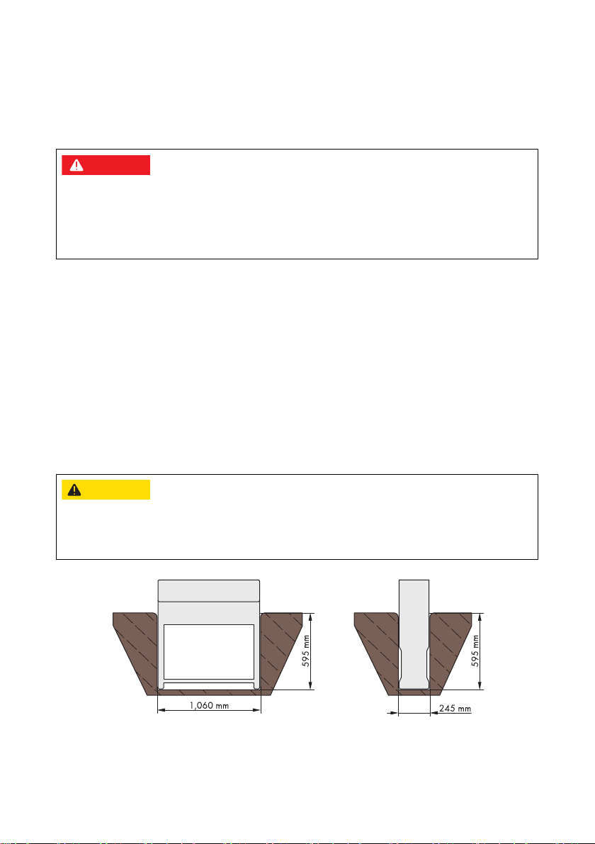
Additionally required mounting material (not included in the scope of delivery):
• 4 M8 screws. Take wall properties into account when choosing the type of screws.
•4 washers
• If necessary, 4 wall plugs. Take wall properties into account when choosing the wall plugs.
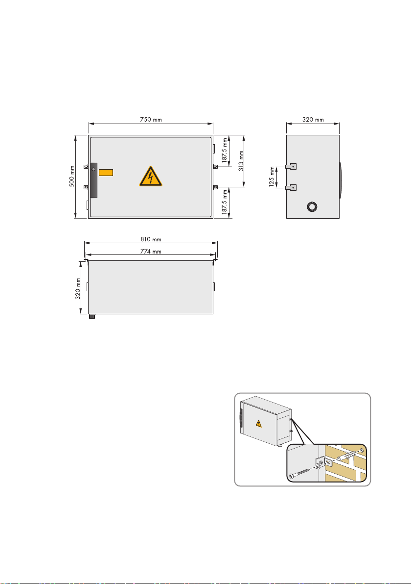
Figure7: Dimensions of the Sunny Main Box
1. Mark the position of the drill holes on the wall or array substructure.
2. Drill holes at the marked positions.
3. If necessary, insert wall plugs.
4. Fasten the Sunny Main Box to the wall or array
substructure using suitable screws and washers.
5. Make sure that the Sunny Main Box is securely in place.
Installation Manual SMB-IA-en-10 17
Page 18
5 Assembly SMA Solar Technology AG
%"/(&3
$"65*0/
5.2 Mounting the Sunny Main Box Cabinet
5.2.1 Selecting the Mounting Location
Danger to life due to fire or explosion
• Do not mount the Sunny Main Box Cabinet on flammable construction materials.
• Do not mount the Sunny Main Box Cabinet in areas containing highly flammable materials.
• Do not mount the Sunny Main Box Cabinet in potentially explosive atmospheres.
Requirements for the mounting location:
☐ The mounting location should not be in a living or office area.
☐ The mounting location must not block any escape routes.
☐ The mounting location must be freely and safely accessible at all times without any need for
auxiliary equipment (such as scaffolding or lifting platforms). Non-fulfillment of these criteria
may restrict servicing.
☐ The foundation at the mounting location must be suitable for the weight and size of the
Sunny Main Box Cabinet (see Section 10"Technical Data",page29).
☐ The mounting location must not be exposed to direct solar irradiation.
5.2.2 Mounting the Base
Danger of crushing if the base of the Sunny Main Box Cabinet is dropped
• During transport, take into account the weight of the base of the Sunny Main Box Cabinet of
19 kg.
1. Dig the foundation pit. Observe a base installation depth of 600 mm.
18 SMB-IA-en-10 Installation Manual
Page 19

SMA Solar Technology AG 5 Assembly
/05*$&
$"65*0/
2. Place the base of the Sunny Main Box Cabinet in the excavated pit in such way that the side
with the kick plate points to the front.
3. Remove the upper kick plate.
4. Presort the connection cables according to position and lay them in the base.
5. Half-fill the pit with gravel or sand. Gravel size: 2 mm … 4 mm.
6.
Damage to the Sunny Main Box Cabinet due to moisture penetration
Penetrating moisture can lead to condensation, corrosion, and leakage currents. The use of a
base filler stops condensation forming.
• Fill the remaining space around the base with base filler. Filler size: 4 mm … 8 mm.
5.2.3 Mounting the Sunny Main Box Cabinet on the Base
Danger of crushing if the Sunny Main Box Cabinet is dropped.
• When mounting the Sunny Main Box Cabinet, take its weight of 96 kg into account.
• Transport the Sunny Main Box Cabinet using appropriate hoist.
1. Remove the 4 fastening screws from the base plate of the Sunny Main Box Cabinet.
2. Place the Sunny Main Box Cabinet on the base.
3. Fasten the Sunny Main Box Cabinet to the base with the previously removed screws
(torque: 10 Nm)
4. Ensure that the Sunny Main Box Cabinet is securely attached.
5. Lead the connection cables through the base plate into the Sunny Main Box Cabinet and fasten
to the internal cable support rail.
6. To prevent the upper kick plate being opened by unauthorised persons, insert the 2 safety
screws on the inside of the base plate.
Installation Manual SMB-IA-en-10 19
Page 20
6 Electrical Connection SMA Solar Technology AG
6 Electrical Connection
6.1 Overview of the Connection Area
6.1.1 Sunny Main Box
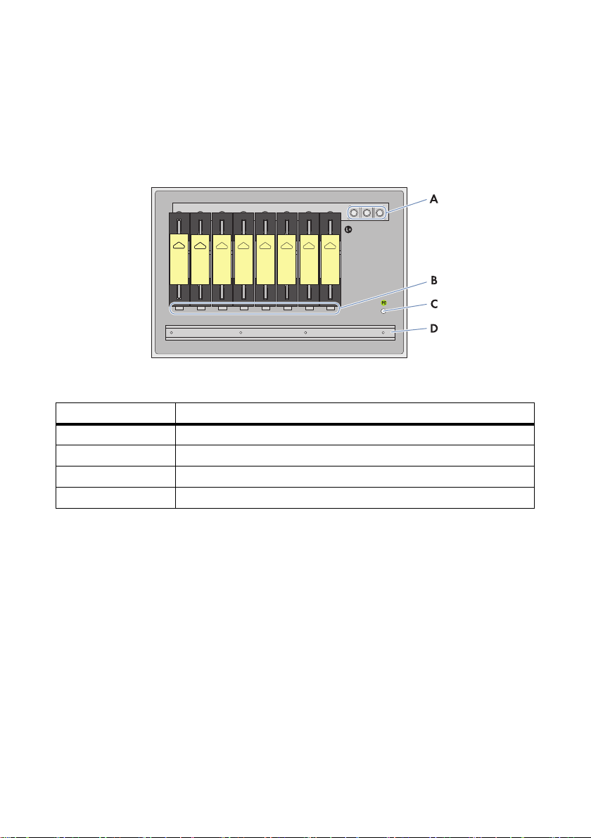
Figure8: Connection area of the Sunny Main Box
Position Designation
ADC output
BDC input
CEarth cable connection
D Cable support rail
20 SMB-IA-en-10 Installation Manual
Page 21
SMA Solar Technology AG 6 Electrical Connection
6.1.2 Sunny Main Box Cabinet
Sunny Main Box Cabinet with 2 x 8 inputs
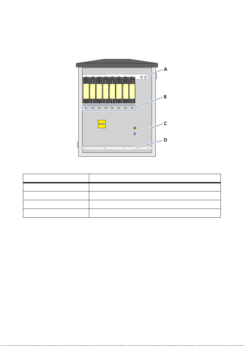
Figure9: Connection area of the Sunny Main Box Cabinet with 2 x 8 inputs
Position Designation
ADC output
BDC input
C Earth cable connection
D Cable support rail
Installation Manual SMB-IA-en-10 21
Page 22

6 Electrical Connection SMA Solar Technology AG
Sunny Main Box Cabinet with 2 x 2 x 4 inputs
Figure10: Connection area of the Sunny Main Box Cabinet with 2 x 2 x 4 inputs
Position Designation
ADC output
BDC input
C Earth cable connection
D Cable support rail
22 SMB-IA-en-10 Installation Manual
Page 23

SMA Solar Technology AG 6 Electrical Connection
Sunny Main Box Cabinet with 2 x 2 x 3 inputs
Figure11: Connection area of the Sunny Main Box Cabinet with 2 x 2 x 3 inputs
Position Designation
ADC output
BDC input
C Earth cable connection
D Cable support rail
6.2 Connecting the String Cables to the Fuse Holders
1. Lead the string cables through the cable glands into the enclosure interior. Make sure polarity
is correct.
2. Tighten the cable glands.
3. Cut the string cables to length and strip the insulation.
4. Attach the string cables to the internal cable support rail.
5. Connect the string cables to the bolt clamps of the fuse holders (torque: 35 Nm). Make sure
polarity is correct.
Installation Manual SMB-IA-en-10 23
Page 24

6 Electrical Connection SMA Solar Technology AG
%"/(&3
6.3 Connecting the DC Input Cables
Lethal electric shock due to live voltage
High voltage is present in the DC sub-distributions. Failure to adhere to safety warnings may lead to
severe or lethal injuries from electric shock.
• Observe all safety rules.
– Disconnect
– Ensure that the device cannot be reconnected
– Check that no voltage is present
– Earth and short-circuit
– Cover or shield any adjacent live components.
Requirements:
☐ The correct conductor cross-section for the DC input cables has been selected.
☐ The DC sub-distributions are switched off.
1. Strip 35 mm insulation off the DC input cables.
2. Fit suitable terminal lugs to the DC input cables (see Section 10"Technical Data",page29).
3. Lead the DC input cables through cable glands into the enclosure interior. Make sure polarity
is correct.
4. Tighten the cable glands.
5. Connect the DC input cables to bolt clamps (torque: 30 Nm … 35 Nm).
6. Ensure that the DC input cables are securely in place.
6.4 Connecting the Earth Cable
Requirement:
☐ Earth cable cross-section: at least 16 mm
1. Strip the earth cable by 16 mm.
2. Fit suitable terminal lugs to the earth cable (see Section 10"Technical Data",page29).
3. Lead the earth cable through a cable gland into the enclosure interior.
4. Tighten the cable gland.
5. Connect the earth cable to the earthing bolts (torque: 14 Nm).
6. Ensure that the earth cable is securely in place.
7. Earth the earth cable in the vicinity of the Sunny Main Box or Sunny Main Box Cabinet, for
example, with an earth rod.
24 SMB-IA-en-10 Installation Manual
2
Page 25

SMA Solar Technology AG 7 Requirements for Commissioning
7 Requirements for Commissioning
During commissioning of the Sunny Main Box or Sunny Main Box Cabinet, the commissioning report
must be filled in. The commissioning report is enclosed with the central inverter.
Requirements:
☐ The D C in put cab les are c onn ect ed t o th e in ver ter and are a cti vated. Th ere is no reverse v oltag e
from the inverter.
☐ All connections are executed according to this manual (see Section 6"Electrical
Connection",page20).
☐ It has been verified that all fuses are firmly in place.
☐ The ground around the Sunny Main Box or Sunny Main Box Cabinet is paved and provides
suitable access.
Installation Manual SMB-IA-en-10 25
Page 26
8 Disconnecting the Sunny Main Box or Sunny Main Box Cabinet SMA Solar Technology AG
%"/(&3
%"/(&3
$"65*0/
8 Disconnecting the Sunny Main Box or
Sunny Main Box Cabinet
Danger to life due to electric shock when live components are touched.
High voltages are present in the central inverter, the DC sub-distributions and the Sunny Main Box
or Sunny Main Box Cabinet. Failure to adhere to safety warnings may lead to severe or lethal
injuries from electric shock.
• Observe the following safety rules when disconnecting:
– Disconnect.
– Ensure that the device cannot be reconnected.
– Check that no voltage is present.
– Earth and short-circuit.
– Cover or shield any adjacent live components.
Danger to life due to electric shock
Hazardous voltages may still be present in the inverter even if the AC and DC main switches are
switched off.
• After disconnecting the inverter, wait at least 15 minutes for the capacitors to discharge
completely.
Risk of burns from touching hot components
The comp onent s of th e DC su b-dis tribu tions and the central inv erter can get very hot. Touching these
components may cause burns.
• Do not touch hot components.
• Wait until hot components have cooled down sufficiently.
• Observe all safety warnings in the DC sub-distributions and the inverter.
• Wear safety gloves when working on the device.
26 SMB-IA-en-10 Installation Manual
Page 27

SMA Solar Technology AG 8 Disconnecting the Sunny Main Box or Sunny Main Box Cabinet
%"/(&3
Procedure:
1.
Danger to life due to electric shock
• Only open the disconnection unit of the Sunny String-Monitor when it is switched off.
– Disconnect the DC sub-distributions (see installation manual of these devices).
2. Disconnect central inverter (see installation manual of the central inverter).
3. If there are DC fuses in the central inverter, only pull them out once the inverter is disconnected
and using the LV/HRC fuse handle.
4. If there are no DC fuses in the central inverter, pull out the fuses in the DC main distribution.
5. Release all screw connections.
Installation Manual SMB-IA-en-10 27
Page 28

9 Decommissioning SMA Solar Technology AG
9 Decommissioning
9.1 Dismantling Sunny Main Box and Sunny Main Box Cabinet
Requirement:
☐ Sunny Main Box or Sunny Main Box Cabinet are disconnected (see Section 8"Disconnecting
the Sunny Main Box or Sunny Main Box Cabinet",page26).
1. Remove the fuses.
2. Release cables from the cable fastenings.
3. Release all cable glands.
9.2 Disposing of Sunny Main Box and Sunny Main Box Cabinet
• Dispose of the Sunny Main Box or Sunny Main Box Cabinet in accordance with the locally
applicable disposal regulations for electronic waste.
or
Return the Sunny Main Box or Sunny Main Box Cabinet to SMA Solar Technology AG at your
own expense (see Section 11"Contact",page34). Label the packaging
"ZUR ENTSORGUNG" ("FOR DISPOSAL").
28 SMB-IA-en-10 Installation Manual
Page 29
SMA Solar Technology AG 10 Technical Data
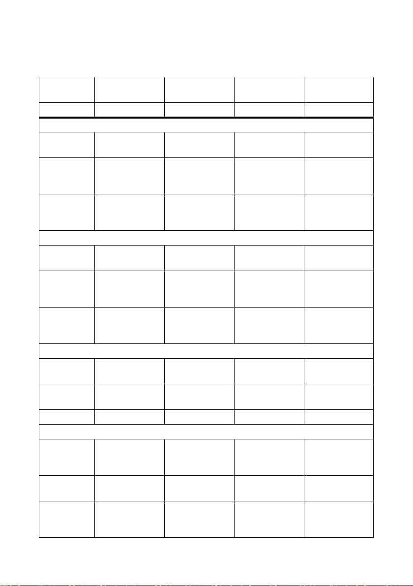
10 Technical Data
Sunny Main Box Sunny Main Box
Cabinet
Option 8 inputs 2 x 8 inputs 2 x 2 x 4 inputs 2 x 2 x 3 inputs
Enclosure
Outdoor
installation
Type of
mounting: on
base
Type of
mounting: on
wall
Mechanical Data of Base
Width x height
x depth
Installation
depth of the
base
Total weight of
enclosure and
base
Mechanical Data of Enclosure
Width x height
x depth
Depth of lock
cylinder
Weight 35 kg 96 kg 96 kg 96 kg
Input Data
Maximum
permissible
DC voltage
Number of
DC inputs
Maximum
number of
LV/HRC fuses
shaded shaded shaded shaded
no yes yes yes
yesnonono
‒ 785 mm x 950 mm
x 480 mm
‒ 600 mm 600 mm 600 mm
‒ 115 kg 115 kg 115 kg
750 mm x 500 mm
x 320 mm
40 mm 40 mm 40 mm 40 mm
1,000 V 1,000 V 1,000 V 1,000 V
8 2 x 8 2 x 2 x 4 2 x 2 x 3
8 161612
800 mm x 950 mm
x 550 mm
Sunny Main Box
Cabinet
785 mm x 950 mm
x 480 mm
800 mm x 950 mm
x 550 mm
Sunny Main Box
Cabinet
785 mm x 950 mm
x 480 mm
800 mm x 950 mm
x 550 mm
Installation Manual SMB-IA-en-10 29
Page 30
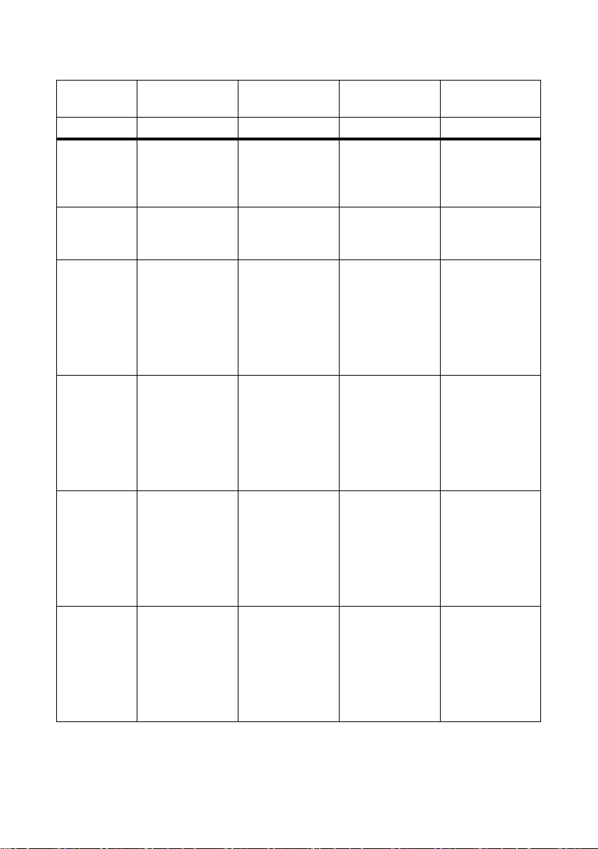
10 Technical Data SMA Solar Technology AG
Sunny Main Box Sunny Main Box
Cabinet
Sunny Main Box
Cabinet
Sunny Main Box
Cabinet
Option 8 inputs 2 x 8 inputs 2 x 2 x 4 inputs 2 x 2 x 3 inputs
Maximum
8886
number of
disconnect
blades
Possible sizes
of LV/HRC
fuses
Maximum
80 A / 100 A /
125 A / 160 A
80 A / 100 A /
125 A / 160 A
80 A / 100 A /
125 A / 160 A
52 A 52 A 52 A 52 A
80 A / 100 A /
125 A / 160 A /
200 A
operating
current per
measuring
input with
80 A LV/HRC
fuse
Maximum
65 A 65 A 65 A 65 A
operating
current per
measuring
input with
100 A
LV/HRC fuse
Maximum
81A81A81A81A
operating
current per
measuring
input with
125 A
LV/HRC fuse
Maximum
104 A 104 A 104 A 104 A
operating
current per
measuring
input with
160 A
LV/HRC fuse
30 SMB-IA-en-10 Installation Manual
Page 31
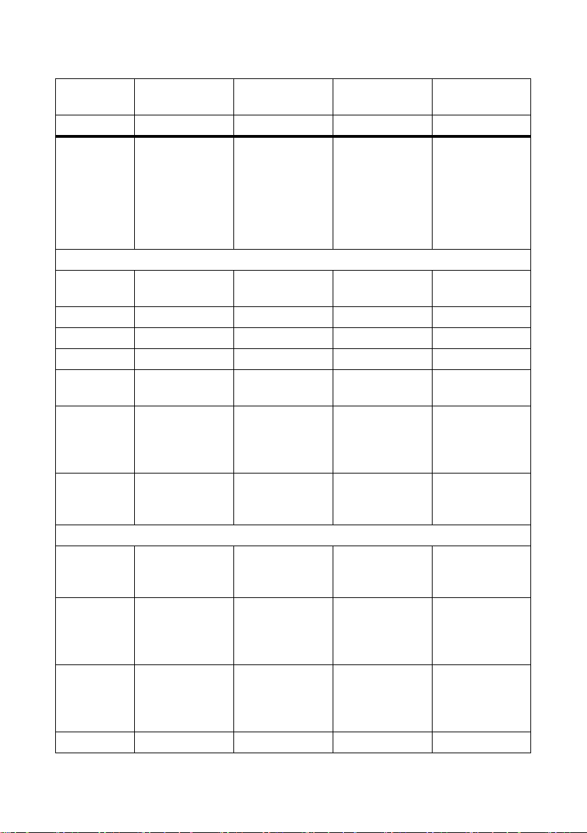
SMA Solar Technology AG 10 Technical Data
Sunny Main Box Sunny Main Box
Cabinet
Sunny Main Box
Cabinet
Sunny Main Box
Cabinet
Option 8 inputs 2 x 8 inputs 2 x 2 x 4 inputs 2 x 2 x 3 inputs
Maximum
‒‒‒130A
operating
current per
measuring
input with
200 A
LV/HRC fuse
DC input
Sc rews for f use
M10 M10 M10 M10
holders
Torque 30 Nm … 35 Nm 30 Nm … 35 Nm 30 Nm … 35 Nm 30 Nm … 35 Nm
Cable gland 8 x M40 ‒ ‒ ‒
Sealing range 14 mm … 28 mm ‒ ‒ ‒
Seal insert pre-
14 mm … 18 mm ‒ ‒ ‒
mounted
Seal insert
included in
scope of
delivery
Maximum
7 mm …
20.5 mm /
20 mm … 25 mm /
24 mm … 28 mm
2
240 mm
‒‒‒
240 mm
2
240 mm
2
240 mm
2
cable crosssection
DC output
Diameter of
3 x 13 mm 2 x 3 x 13 mm 2 x 2 x 2 x 13 mm 2 x 2 x 2 x 13 mm
through-hole in
busbar
Maximum
240 mm
2
240 mm
2
240 mm
2
240 mm
2
cross-section
of standard
terminal lug
Screws
included in
3 x M12 /
2xM12*
2 x 3 x M12 2 x 2 x 2 x M12 2 x 2 x 2 x M12
scope of
delivery
Torque 74 Nm 74 Nm 74 Nm 74 Nm
Installation Manual SMB-IA-en-10 31
Page 32
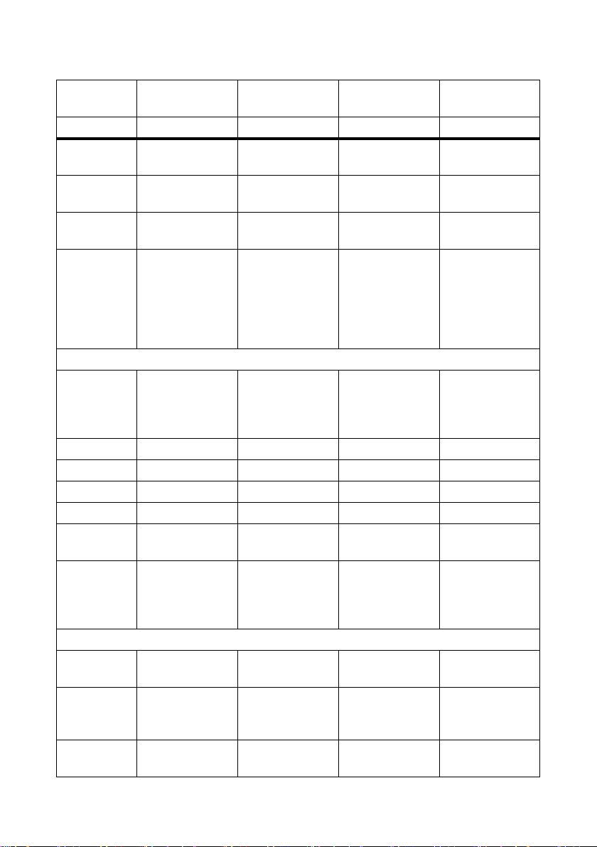
10 Technical Data SMA Solar Technology AG
Sunny Main Box Sunny Main Box
Cabinet
Sunny Main Box
Cabinet
Sunny Main Box
Cabinet
Option 8 inputs 2 x 8 inputs 2 x 2 x 4 inputs 2 x 2 x 3 inputs
Cable gland 3 x M40 /
‒‒‒
2xM50*
Sealing range
14 mm … 28 mm /
‒‒‒
27 mm … 36 mm*
Seal insert premounted
Seal insert
included in
scope of
delivery
14 mm … 28 mm /
27 mm … 36 mm
17 mm …
20.5 mm /
20 mm … 25 mm /
24 mm … 28 mm /
‒‒‒
‒‒‒
29 mm … 34 mm /
32 mm … 36 mm
Protective conductor
Maximum
95 mm
2
240 mm
2
240 mm
2
240 mm
cross-section
of standard
terminal lug
Stud bolt M8 M12 M12 M12
Torque 14 Nm 74 Nm 74 Nm 74 Nm
Cable gland M32 ‒ ‒ ‒
Sealing range 9 mm … 20.5 mm ‒ ‒ ‒
Seal insert pre-
9 mm … 13 mm ‒ ‒ ‒
mounted
Seal insert
included in
scope of
delivery
11.5 mm …
15.5 mm /
14 mm … 18 mm /
17 mm... 20.5 mm
‒‒‒
Degree of Protection and Ambient Conditions
Degree of
IP54 IP54 IP54 IP54
protection
Permissible
‒25°C … +40°C ‒25°C … +40°C ‒25°C … +40°C ‒25°C … +40°C
ambient
conditions
Relative
15% … 95% 15% … 95% 15% … 95% 15% … 95%
humidity
2
32 SMB-IA-en-10 Installation Manual
Page 33

SMA Solar Technology AG 10 Technical Data
Sunny Main Box Sunny Main Box
Cabinet
Sunny Main Box
Cabinet
Sunny Main Box
Cabinet
Option 8 inputs 2 x 8 inputs 2 x 2 x 4 inputs 2 x 2 x 3 inputs
Maximum
1,000 m 1,000 m 1,000 m 1,000 m
height above
MSL
* With smaller stud bolts, allow for proportionately smaller cable gland and sealing range.
Installation Manual SMB-IA-en-10 33
Page 34

11 Contact SMA Solar Technology AG
11 Contact
If you have technical problems concerning our products, contact the SMA Service Line. We require
the following information in order to provide you with the necessary assistance:
• Device type and serial number of the Sunny Main Box
• Device type and serial number of the Sunny Main Box Cabinet
• Type and number of connected PV modules
SMA Solar Technology AG
Sonnenallee 1
34266 Niestetal, Germany
www.SMA.de
SMA Service Line
Tel. +49 561 9522 299
Fax: +49 561 9522 3299
E‑Mail: SunnyCentral.Service@SMA.de
34 SMB-IA-en-10 Installation Manual
Page 35

SMA Solar Technology AG Legal Restrictions
Legal Restictions
The information contained in this document is the property of SMA Solar Technology AG. Publishing its content, either partially or
in full, requires the written permission of SMA Solar Technology AG. Any internal company copying of the document for the
purposes of evaluating the product or its correct implementation is allowed and does not require permission.
SMA Factory Warranty
The current warranty conditions come enclosed with your device. These are also available online at www.SMA-Solar.com and can
be downloaded and are available on paper from the usual sales channels if required.
Trademarks
All trademarks are recognized even if these are not marked separately. Missing designations do not mean that a product or brand
is not a registered trademark.
The Bluetooth
SMA Solar Technology AG is under licence.
QR Code
SMA Solar Technology AG
Sonnenallee 1
34266 Niestetal
Germany
Tel. +49 561 9522-0
Fax +49 561 9522-100
www.SMA.de
E-Mail: info@SMA.de
© 2004 to 2012 SMA Solar Technology AG. All rights reserved
®
word mark and logos are registered trademarks owned by Bluetooth SIG, Inc. and any use of such marks by
®
is a registered trademark of DENSO WAVE INCORPORATED.
Installation Manual SMB-IA-en-10 35
Page 36

SMA Solar Technology AG
XXX4."4PMBSDPN
4."4PMBS5FDIOPMPHZ
4."4PMBS5FDIOPMPHZ"(
XXX4."EF
4.""NFSJDB--$
XXX4.""NFSJDBDPN
4."5FDIOPMPHZ"VTUSBMJB1UZ-UE
XXX4.""VTUSBMJBDPNBV
4."#FOFMVY413-
XXX4."#FOFMVYDPN
4."#FJKJOH$PNNFSDJBM$P-UE
XXX4."$IJOBDPN
4."$[FDI3FQVCMJDTSP
XXX4."$[FDIDPN
4."'SBODF4"4
XXX4."'SBODFDPN
4.")FMMBT"&
XXX4.")FMMBTDPN
4."*C©SJDB5FDOPMPHB4PMBS4-
XXX4."*CFSJDBDPN
4."*UBMJB4SM
XXX4."*UBMJBDPN
4."5FDIOPMPHZ,PSFB$P-UE
XXX4.",PSFBDPN
36 SMB-IA-en-10 Installation Manual
 Loading...