

Page 1
US
Accessories for Sunny Island
SMARTFORMER FOR SUNNY ISLAND
Installation Manual
SI_TDBOX-IA-eng-IUS122211 | IMEN-SITDBOX-US | Version 1.1
Page 2

Page 3

SMA America, LLC Legal Restrictions
Copyright © 2012 SMA America,LLC. All rights reserved.
No part of this document may be reproduced, stored in a retrieval system, or transmitted, in any form
or by any means, electronic, mechanical, photographic, magnetic or otherwise, without the prior
written permission of SMA America,LLC.
SMA America,LLC doesn’t make representations, express or implied, with respect to this
do cum ent ati on o r an y of the equip men t an d/o r so ftw are it m ay d escribe, including (with no limitation)
any implied warranties of utility, merchantability, or fitness for any particular purpose. All such
warranties are expressly disclaimed. Neither SMA America,LLC nor its distributors or dealers shall
be liable for any indirect, incidental, or consequential damage under any circumstances.
(The exclusion of implied warranties may not apply in all cases under some statutes, and thus the
above exclusion may not apply.)
Specifications are subject to change without notice. Every attempt has been made to make this
document complete, accurate and up-to-date. Readers are cautioned, however, that
SMAAmerica,LLC reserves the right to make changes without notice and shall not be responsible for
any damage, including indirect, incidental or consequential damage, caused by reliance on the
material presented, including, but not limited to, omissions, typographical errors, arithmetical errors or
listing errors in the content material.
All trademarks are recognized even if these are not marked separately. Missing designations do not
mean that a product or brand is not a registered trademark.
SMA America, LLC
3801 N. Havana Street
Denver, CO 80239 U.S.A.
Installation Manual SI_TDBOX-IA-eng-IUS122211 3
Page 4
Important Safety Instructions SMA America, LLC
IMPORTANT SAFETY INSTRUCTIONS
SAVE THESE INSTRUCTIONS
This manual contains important instructions for the following product:
• Smartformer for Sunny Island
This manual must be followed during installation and maintenance.
The product is designed and tested according to international safety requirements, but as with all
electrical and electronic equipment, certain precautions must be observed when installing and/or
operating the product. To reduce the risk of personal injury and to ensure the safe installation and
operation of the product, you must carefully read and follow all instructions, cautions and warnings
in this manual.
Warnings in this document
A warning describes a hazard to equipment or personnel. It calls attention to a procedure or practice,
which, if not correctly performed or adhered to, could result in damage to or destruction of part or all
of the SMA equipment and/or other equipment connected to the SMA equipment, or in personal
injury.
Symbol Description
DANGER indicates a hazardous situation which, if not avoided, will result in
death or serious injury.
WARNING indicates a hazardous situation which, if not avoided, could result
in death or serious injury.
CAUTION indicates a hazardous situation which, if not avoided, could result
in minor or moderate injury.
NOTICE is used to address practices not related to personal injury.
4 SI_TDBOX-IA-eng-IUS122211 Installation Manual
Page 5

SMA America, LLC Important Safety Instructions
Other Symbols in this document
In addition to the safety and hazard symbols described on the previous pages, the following symbols
are also used in this manual:
Symbol Description
Indicates information that is important for a specific topic or objective, but is not
safety-relevant.
☐ Indicates a requirement for meeting a specific goal.
☑ Desired result
✖A problem that could occur
Markings on this product
The following symbols are used as product markings with the following meanings.
Symbol Description
Warning regarding dangerous voltage
The product works with high voltages. All work on the product must only be
performed as described in the documentation of the product.
Risk of Fire
Improper installation of the product may cause a fire.
Beware of hot surface
The product can become hot during operation. Do not touch the product during
operation.
Observe the operating instructions
Read the documentation of the product before working on it. Follow all safety
precautions and instructions as described in the documentation.
UL1741 is the standard applied by Underwriters Laboratories to the product to
certify that it meets the requirements of the NationalElectricalCode
Installation Manual SI_TDBOX-IA-eng-IUS122211 5
®
.
Page 6

General Warnings SMA America, LLC
General Warnings
General Warnings
All electri cal installations m ust be done in accordance with the local and NationalElectrical Code
ANSI/NFPA 70 or the Canadian Electrical Code® CSAC22.1. This document does not and is not
intended to replace any local, state, provincial, federal or national laws, regulation or codes
applicable to the installation and use of the product, including without limitation applicable
electrical safety codes. All installations must conform with the laws, regulations, codes and
standards applicable in the jurisdiction of installation. SMA assumes no responsibility for the
compliance or noncompliance with such laws or codes in connection with the installation of the
product.
The product contains no user-serviceable parts. For all repair and maintenance, always return the
unit to an authorized SMA Service Center.
Before installing or using the product, read all of the instructions, cautions, and warnings in this
manual.
Before connecting the product to the electrical utility grid, contact the local utility company. This
connection must be made only by qualified personnel.
Wiring of the product must be made by qualified personnel only.
®
6 SI_TDBOX-IA-eng-IUS122211 Installation Manual
Page 7

SMA America, LLC Table of Contents
Table of Contents
1 Information on this Document. . . . . . . . . . . . . . . . . . . . . . 11
2 Safety . . . . . . . . . . . . . . . . . . . . . . . . . . . . . . . . . . . . . . . . . 12
2.1 Intended Use. . . . . . . . . . . . . . . . . . . . . . . . . . . . . . . . . . . . . . . 12
2.2 Qualification of Skilled Workers. . . . . . . . . . . . . . . . . . . . . . . . 13
2.3 Safety Precautions. . . . . . . . . . . . . . . . . . . . . . . . . . . . . . . . . . . 14
3 Scope of Delivery. . . . . . . . . . . . . . . . . . . . . . . . . . . . . . . . 15
4 Product Description . . . . . . . . . . . . . . . . . . . . . . . . . . . . . . 16
4.1 Smartformer for Sunny Island . . . . . . . . . . . . . . . . . . . . . . . . . . 16
4.2 Autotransformer . . . . . . . . . . . . . . . . . . . . . . . . . . . . . . . . . . . . 17
4.3 Bypass Switch . . . . . . . . . . . . . . . . . . . . . . . . . . . . . . . . . . . . . . 18
4.4 Load-Shedding Contactor . . . . . . . . . . . . . . . . . . . . . . . . . . . . . 18
4.5 Miniature Circuit-Breaker . . . . . . . . . . . . . . . . . . . . . . . . . . . . . 19
4.6 Overload Protection . . . . . . . . . . . . . . . . . . . . . . . . . . . . . . . . . 20
4.7 Type Label . . . . . . . . . . . . . . . . . . . . . . . . . . . . . . . . . . . . . . . . 21
5 Mounting. . . . . . . . . . . . . . . . . . . . . . . . . . . . . . . . . . . . . . . 22
5.1 Selecting the Mounting Location. . . . . . . . . . . . . . . . . . . . . . . . 22
5.2 Mounting the Anchorage Brackets on the
Enclosure Rear Wall . . . . . . . . . . . . . . . . . . . . . . . . . . . . . . . . . 26
5.3 Mounting the Smartformer on a Masonry Wall . . . . . . . . . . . . 28
5.4 Mounting the Smartformer on a Wooden Wall . . . . . . . . . . . . 29
Installation Manual SI_TDBOX-IA-eng-IUS122211 7
Page 8

Table of Contents SMA America, LLC
6 Electrical Connection . . . . . . . . . . . . . . . . . . . . . . . . . . . . . 31
6.1 Safety during Electrical Connection . . . . . . . . . . . . . . . . . . . . . 31
6.2 Overview of the Connection Area . . . . . . . . . . . . . . . . . . . . . . 32
6.2.1 View from Below. . . . . . . . . . . . . . . . . . . . . . . . . . . . . . . . . . . . . . . . . . . . . . 32
6.2.2 View from Above . . . . . . . . . . . . . . . . . . . . . . . . . . . . . . . . . . . . . . . . . . . . . 32
6.2.3 Interior View . . . . . . . . . . . . . . . . . . . . . . . . . . . . . . . . . . . . . . . . . . . . . . . . . 33
6.2.4 System Overview . . . . . . . . . . . . . . . . . . . . . . . . . . . . . . . . . . . . . . . . . . . . . 35
6.3 Selecting Cables. . . . . . . . . . . . . . . . . . . . . . . . . . . . . . . . . . . . 36
6.4 Inserting the Cables . . . . . . . . . . . . . . . . . . . . . . . . . . . . . . . . . 37
6.5 Connecting Insulated Conductors to Spring Clamp Terminals . 39
6.6 Connecting Loads . . . . . . . . . . . . . . . . . . . . . . . . . . . . . . . . . . . 40
6.7 Connecting the PV Plant . . . . . . . . . . . . . . . . . . . . . . . . . . . . . . 41
6.8 Connecting the Generator or Power Distribution Grid . . . . . . . 42
6.9 Connecting the Sunny Island . . . . . . . . . . . . . . . . . . . . . . . . . . 43
6.10 Connecting the Load-Shedding Contactor . . . . . . . . . . . . . . . . 44
7 Commissioning . . . . . . . . . . . . . . . . . . . . . . . . . . . . . . . . . . 46
8 Setting the Operating Mode via the Bypass Switch . . . . 50
9 Mounting and Disassembling the Contact Hazard
Protection Cover. . . . . . . . . . . . . . . . . . . . . . . . . . . . . . . . . 51
9.1 Disassembling the Contact Hazard Protection Cover. . . . . . . . 52
9.2 Mounting the Contact Hazard Protection Cover . . . . . . . . . . . 53
10 Disconnecting the Smartformer from the
Power Supply . . . . . . . . . . . . . . . . . . . . . . . . . . . . . . . . . . . 55
11 Cleaning . . . . . . . . . . . . . . . . . . . . . . . . . . . . . . . . . . . . . . . 57
8 SI_TDBOX-IA-eng-IUS122211 Installation Manual
Page 9

SMA America, LLC Table of Contents
12 Troubleshooting . . . . . . . . . . . . . . . . . . . . . . . . . . . . . . . . . 58
12.1 Activating Overload Protection. . . . . . . . . . . . . . . . . . . . . . . . . 58
12.2 Replacing Miniature Circuit-Breakers "F4" and "F5" . . . . . . . . . 59
13 Decommissioning . . . . . . . . . . . . . . . . . . . . . . . . . . . . . . . . 62
13.1 Disassembling the Smartformer. . . . . . . . . . . . . . . . . . . . . . . . . 62
13.2 Storing the Smartformer . . . . . . . . . . . . . . . . . . . . . . . . . . . . . . 63
13.3 Packaging the Smartformer. . . . . . . . . . . . . . . . . . . . . . . . . . . . 63
13.4 Disposing of the Smartformer . . . . . . . . . . . . . . . . . . . . . . . . . . 63
14 Technical Data . . . . . . . . . . . . . . . . . . . . . . . . . . . . . . . . . . 64
15 Compliance Information . . . . . . . . . . . . . . . . . . . . . . . . . . 70
16 Contact . . . . . . . . . . . . . . . . . . . . . . . . . . . . . . . . . . . . . . . . 71
Installation Manual SI_TDBOX-IA-eng-IUS122211 9
Page 10

Table of Contents SMA America, LLC
10 SI_TDBOX-IA-eng-IUS122211 Installation Manual
Page 11

SMA America, LLC 1 Information on this Document
1 Information on this Document
Validity
This document applies to device type SI-TD-BOX, hardware version 1.0 and higher.
Target Group
This document is for skilled workers. Only qualified personnel are allowed to perform the tasks set
forth in this document (see Section 2.2 "Qualification of Skilled Workers", page 13).
Typography
Typography Usage Example
"light" • Terminals
• Spring clamp terminals
•Screw terminals
bold • Switch settings that you
should select
• Connect the L conductor of the AC 1
terminal of the Sunny Island to the
lower spring clamp terminal in
connecting terminal plate
"Sunny Island AC1 L".
• To have the connected loads supplied
by the Sunny Island, set the bypass
switch to ION.
Nomenclature
The following nomenclature is used in this document:
Complete designation Designation in this document
SMA Solar Technology America, LLC SMA
Smartformer for Sunny Island "Smartformer" or "product"
Sunny Boy PV inverter
Abbreviations
Abbreviation Designation Explanation
AC Alternating Current ‒
DC Direct Current ‒
PE Protective Earth ‒
PV Photovoltaics ‒
Installation Manual SI_TDBOX-IA-eng-IUS122211 11
Page 12
2 Safety SMA America, LLC
SMARTFORMER
Loads
Generator
PV inverter
Battery
PV array
Power
distribution grid
Sunny Island
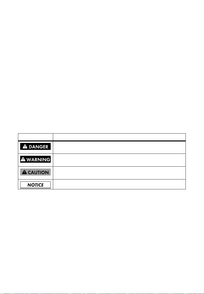
2Safety
2.1 Intended Use
Figure 1: Principle of a simple Sunny Island system with Smartformer
The Smartformer for Sunny Island is a pre-wired AC distribution board with an autotransformer,
bypass switch, load-shedding contactor, overload protection, and miniature circuit-breakers.
Mounting requirements:
The Smartformer is only suitable for indoor use. Do not mount the Smartformer outdoors.
• Do not mount the Smartformer on flammable construction materials.
• Do not mount the Smartformer near highly flammable materials.
• Do not mount the Smartformer in potentially explosive atmospheres.
12 SI_TDBOX-IA-eng-IUS122211 Installation Manual
Page 13

SMA America, LLC 2 Safety
Electrical connection requirements:
The Smartformer must only be used with the following Sunny Island inverters:
• Sunny Island 4548‑US / 6048‑US
• Sunny Island 5048-US with labeling "Smartformer compatible" on the original packaging
Sunny Island 5048-US inverters without labeling "Smartformer compatible" on the original
packaging require an additional fuse outside of the Smartformer for Sunny Island (see
Section6.3 "Selecting Cables", page 36).
The Smartformer may be used with the following PV inverters by SMA:
• Sunny Boy 2000HF-US / 2500HF-US / 3000HF-US
• Sunny Boy 3000-US / 3800-US / 4000-US
• Sunny Boy 5000-US / 6000-US
• In off-grid systems: Sunny Boy 7000-US / 8000-US
A generator or the power distribution grid may be connected to the Smartformer. The generator or
the power distribution grid may supply the Sunny Island system with 120 V on 1 line conductor or
with 240 V on 2 line conductors. A generator and the power distribution grid may only be connected
to the Smartformer at the same time if used with an external automatic transfer switch.
General terms of use:
Only use the Smartformer in accordance with the information provided in the enclosed
documentation. Any other use can result in personal injury or property damage.
The enclosed documentation is an integral part of this product.
• Read and adhere to the documentation.
• Keep the documentation in a convenient place for future reference.
Do not operate the Smartformer if it has technical defects.
For safety reasons, it is forbidden to modify the product or install components that are not explicitly
recommended or distributed by SMA.
2.2 Qualification of Skilled Workers
The tasks described in this document are intended for skilled workers only. Skilled workers must have
the following skills:
• Knowledge about the functional principle and operation of off-grid systems and backup systems
• Knowledge of how to deal with the dangers and risks associated with installing and using
electrical devices
• Knowledge of the installation and commissioning of electrical devices
• Knowledge of all applicable standards and guidelines
• Knowledge of and adherence to this document and all safety precautions
Installation Manual SI_TDBOX-IA-eng-IUS122211 13
Page 14

2 Safety SMA America, LLC
2.3 Safety Precautions
Danger to life due to electric shock
High volt ages that can result in electr ic shocks are present in t he live components of the Smartformer.
• Disconnect the Smartformer from the power supply before performing any work on the
Smartformer (see Section 10).
• Always use a contact hazard protection cover when operating the Smartformer.
• Work on the Smartformer may only be performed by a skilled worker.
• Do not touch live components of the Smartformer or other components of the Sunny Island
system.
Risk of injury due to moving parts
A generator can be started automatically by the Sunny Island. Moving parts in the generator can
crush or sever body parts.
• Only operate the generator with safety equipment provided by the manufacturer.
• Install, maintain, and operate the generator according to the manufacturer's specifications.
Risk of injury due to hot components
Components inside the Smartformer may become hot during operation. This may result in burns to
the body.
• Always use a contact hazard protection cover when operating the Smartformer.
• Allow the Smartformer to cool down before removing the contact hazard protection cover.
Property damage due to moisture and dust intrusion
The Smartformer corresponds to the NEMA 1 degree of protection when it is closed and is only
suitable for indoor installation. The intrusion of dust and moisture into the interior can damage the
Smartformer.
• Protect the Smartformer against moisture and dust.
• After working on the Smartformer, mount the contact hazard protection cover and close the
Smartformer.
• While the Smartformer is open, protect it against dust and water.
14 SI_TDBOX-IA-eng-IUS122211 Installation Manual
Page 15

SMA America, LLC 3 Scope of Delivery
3Scope of Delivery
Check the delivery for completeness and any externally visible damage. Contact your specialty
retailer if the delivery is incomplete or you find any damage.
Figure 2: Components included in delivery
Position Quantity Description
A 1 Smartformer
B 4 Anchorage bracket, sealing ring, and hexagon head screw M6x8
C 4 Hexagon socket screw M8x12
D 28 Phillips screw PZ 2
E 1 2-pole miniature circuit-breaker 25 A
F 1 Upper flange plate
G1 Lower flange plate
H 1 Installation manual technical description*
* Information about the circuitry of the Smartformer in the Sunny Island can be found in the technical description.
Installation Manual SI_TDBOX-IA-eng-IUS122211 15
Page 16
4 Product Description SMA America, LLC
4 Product Description
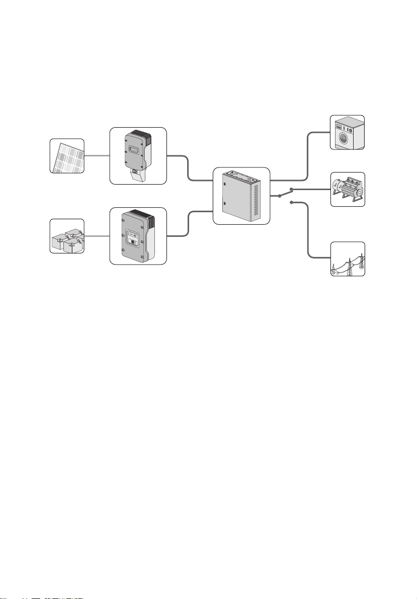
4.1 Smartformer for Sunny Island
The Smartformer for Sunny Island is a pre-wired AC distribution board with an autotransformer,
bypass switch, load-shedding contactor, overload protection, and miniature circuit-breakers.
Figure 3: Structure of the Smartformer
Position Description
A Door handles
BFlange plate
C Ventilation slots
DType label
E Rear wall of enclosure with 8 drill holes
The Smartformer is the AC distribution board in a Sunny Island system with 1 Sunny Island. The
Smartformer provides the terminals for all components in the Sunny Island system. The Smartformer
expands the scope of functions of the Sunny Island with the autotransformer, bypass switch, loadshedding contactor, overload protection, and miniature circuit-breakers.
16 SI_TDBOX-IA-eng-IUS122211 Installation Manual
Page 17

SMA America, LLC 4 Product Description
Symbols on the Smartformer
Symbol Description Explanation
Spring clamp terminals Some of the terminals of the Smartformer are
executed as spring clamp terminals.
Always connect a conductor to a spring
clamp terminal as described in this document
(see Section 6.5 "Connecting Insulated
Conductors to Spring Clamp
Terminals", page 39).
4.2 Autotransformer
The autotransformer enables the following functions in a Sunny Island:
• Integration of PV inverters with an AC output voltage of 240 V
• Supply of AC loads with 120 V or 240 V
The autotransformer converts the input voltage according to the load requirements, operating in the
step-up and step-down operating modes.
•Step-up:
The Sunny Island makes an AC input voltage of 120 V available. The autotransformer converts
this AC input voltage into an AC output voltage of 240 V. The loads use one AC output with
120 V or both AC outputs with 240 V. A different load on the two 120 V outputs is
compensated by the Smartformer through power transmission.
•Step-down:
The PV inverter makes an AC input voltage of 240 V available. The autotransformer converts
this AC input voltage into an AC output voltage 120 V. The Sunny Island uses this voltage to
load the battery.
Unlike in other transformers, the input circuit and the output circuit of the autotransformer are not
galvanically isolated.
Installation Manual SI_TDBOX-IA-eng-IUS122211 17
Page 18

4 Product Description SMA America, LLC
4.3 Bypass Switch
The bypass switch is a manual automatic transfer switch that makes it possible to directly supply the
loads through the generator or power distribution grid. By directly supplying the loads through the
generator or power distribution grid, the Smartformer bypasses the terminals of the PV plant and
Sunny Island. In this way, the Smartformer simplifies maintenance work and repairs.
Figure 4: Overview of the bypass switch
Position Description Explanation
A Switch position "ION" The Sunny Island supplies the loads and, in
doing so, integrates the generator or power
distribution grid, along with the PV plant.
B Switch position "O OFF" The loads are not supplied with voltage.
C Switch position "II ON" Generators or power distribution grids supply
the loads directly.
4.4 Load-Shedding Contactor
The load-shedding contactor is an automatic switch-off device used to protect the battery from deep
discharge.
When a predefined charge status limit of the battery is reached, the Sunny Island triggers the loadshedding contactor. The load-shedding contactor disconnects the loads from the Sunny Island system.
By doing so, the Sunny Island prevents deep battery discharge.
18 SI_TDBOX-IA-eng-IUS122211 Installation Manual
Page 19
SMA America, LLC 4 Product Description
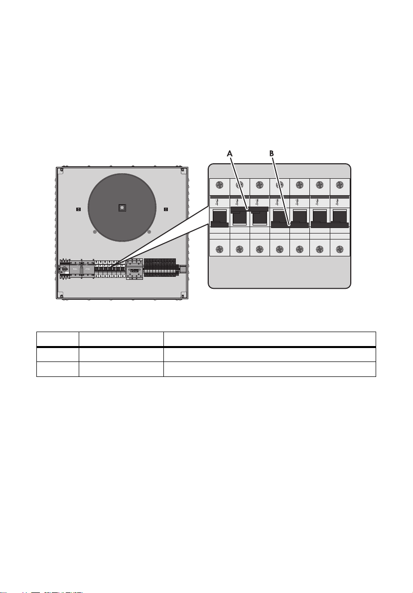
4.5 Miniature Circuit-Breaker
The miniature circuit-breakers protect the connected conductors against destruction due to
overheating. Each of the miniature circuit-breakers can be manually activated or can be tripped
automatically.
To be able to trip automatically, each miniature circuit-breaker monitors the electric current in the
connected conductors. When the current becomes too high, the miniature circuit-breaker interrupts the
flow of current and thus prevents overheating of the conductors.
Figure 5: Overview of the miniature circuit-breakers
Position Description Explanation
A Upper switch position The miniature circuit-breaker is closed.
B Lower switch position The miniature circuit-breaker is open.
Installation Manual SI_TDBOX-IA-eng-IUS122211 19
Page 20

4 Product Description SMA America, LLC
4.6 Overload Protection
The overload protection protects the autotransformer against damage from overheating or a short
circuit. The overload protection identifies overheating or a short circuit by monitoring the currents in
the autotransformer. If currents become too high, the overload protection is tripped with a predefined
time delay. The time delay prevents tripping of the overload protection during brief switch-on current
peaks.
Figure 6: Overview of the overload protection
Position Description Explanation
A Switch position "1" The overload protection is in its normal operating state.
Current is flowing through the primary side and the secondary
side of the autotransformer.
B Switch position "0" The overload protection has been tripped. The current flow is
interrupted on the secondary side of the transformer.
20 SI_TDBOX-IA-eng-IUS122211 Installation Manual
Page 21
SMA America, LLC 4 Product Description
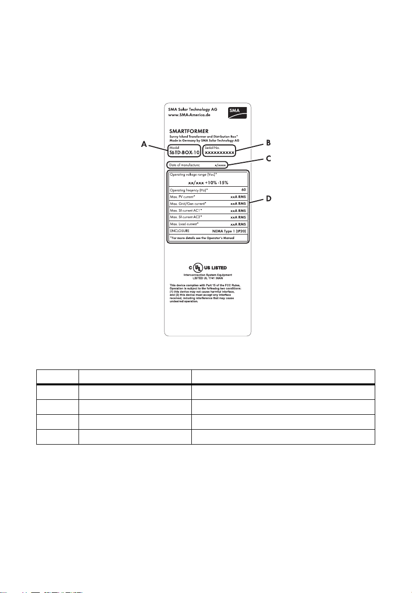
4.7 Type Label
The type label provides a unique identification of the Smartformer. The type label is on the right-hand
side of the enclosure.
Figure 7: Layout of the type label
Position Description Explanation
AModel Device type
B Serial No. Serial number of the Smartformer
C Date of manufacture –
D Device-specific characteristics ‒
Installation Manual SI_TDBOX-IA-eng-IUS122211 21
Page 22

5 Mounting SMA America, LLC
5Mounting
5.1 Selecting the Mounting Location
Danger to life due to fire or explosion
Despite careful construction, electrical devices can cause fires.
• Do not mount the Smartformer on flammable construction materials.
• Do not mount the Smartformer near highly flammable materials.
• Do not mount the Smartformer in potentially explosive atmospheres.
Danger to life due to electric shock
Penetrating moisture may result in voltage being applied to parts of the mounting location.
• Do not mount the Smartformer outdoors.
Destruction of the Smartformer due to direct solar irradiation
Direct solar irradiation can damage the paintwork on the Smartformer enclosure and lead to
enclosure corrosion.
• Ensure that the Smartformer is not exposed to direct solar irradiation.
Requirements for the mounting location:
☐ A firm surface must be available for mounting, such as a masonry wall, studs, or posts. In living
areas, make sure that the surface is no t ma de o f pl ast erb oar d or similar. The Smartformer makes
noises when in use, which can be regarded as a nuisance.
☐ The mounting location must be suitable for the weight and dimensions of the Smartformer
(see Section 14 "Technical Data", page 64).
☐ The mounting location is clear and has safe access at all times without any additional aids being
necessary (such as scaffolding or lifting platforms). Non-fulfillment of these criteria may restrict
servicing.
☐ The ambient conditions are met (see Section 14 "Technical Data", page 64). This ensures
optimal operation of the Smartformer.
☐ The mounting location must not be exposed to direct solar irradiation.
22 SI_TDBOX-IA-eng-IUS122211 Installation Manual
Page 23

SMA America, LLC 5 Mounting
Observe minimum clearances:
Figure 8: Minimum clearances
Destruction of the Smartformer due to insufficient heat dissipation
The Smartformer can overheat if there is insufficient heat dissipation. Frequent overheating can
destroy the Smartformer in the long term.
• Maintain the minimum clearance to walls and adjacent devices or objects. As a result,
sufficient heat dissipation is ensured.
• If the Smartformer is installed together with other electrical devices in areas with high ambient
temperatures, increase the distances between the Smartformer and the other electrical devices
and provide a sufficient fresh-air supply. This prevents the Smartformer from drawing in the
exhaust air from adjacent devices.
• Make sure that there is a distance of at least 391⁄2 in. (1 000 mm) between the door of the
Smartformer and any obstacle in front of it. This makes it easier to open the door of the
Smartformer.
Installation Manual SI_TDBOX-IA-eng-IUS122211 23
Page 24

5 Mounting SMA America, LLC
Selecting the positions of the anchorage brackets on the enclosure rear wall:
Before mounting the anchorage brackets, select 1 of the following 3 options for positioning the
anchorage brackets. This determines the position of the 4 drill holes.
Figure 9: Dimensions with outer drill holes and vertical position of anchorage brackets
Figure 10: Dimensions with inner drill holes and vertical position of anchorage brackets
24 SI_TDBOX-IA-eng-IUS122211 Installation Manual
Page 25

SMA America, LLC 5 Mounting
Figure 11: Dimensions with outer drill holes and horizontal position of anchorage brackets
• When mounting the Smartformer on a wooden wall, ensure that the distance between the
middle of one stud and the middle of the next stud equals the horizontal distance between the
drill holes.
Observe permitted mounting position:
Figure 12: Permitted mounting position and prohibited mounting position
• Mount the Smartformer in the permitted mounting position.
• Position the upper enclosure side horizontally. Tip: Use a spirit level.
Installation Manual SI_TDBOX-IA-eng-IUS122211 25
Page 26

5 Mounting SMA America, LLC
5.2 Mounting the Anchorage Brackets on the Enclosure Rear Wall
Risk of injury due to falling Smartformer
Due to its heavy weight, the Smartformer can crush or break bones if it falls.
• When mounting, take into account the weight of the Smartformer, which is 132
• Make sure that the Smartformer does not tilt or move out of position during mounting.
1. Place the Smartformer on a firm substructure and
open the enclosure door using the door handles.
2. Disassemble the contact hazard protection cover (see Section 9.1).
3. 2 position anchorage brackets on the upper drill
holes in the enclosure rear wall. When doing so,
ke ep t he a nchor age bra cke ts i n the c hos en p osi tion
and align the metal bars of the anchorage bracket
with the enclosure door.
1
⁄2lbs. (60 kg).
4. Screw on both anchorage brackets:
• Insert the hexagon socket screw with the sealing
ring through the drill hole from the inside and
into the thread of the anchorage bracket.
26 SI_TDBOX-IA-eng-IUS122211 Installation Manual
Page 27

SMA America, LLC 5 Mounting
• Tighten the hexagon socket screw
(torque: 88 in-lbs. (10 Nm)).
Use a torque wrench with an attachment for
hexagon socket screws 3⁄16in. (5 mm).
5. Turn the Smartformer by 180°.
6. 2 position anchorage brackets on the upper drill
holes in the enclosure rear wall. When doing so,
ke ep t he a nchor age bra cke ts i n the c hos en p osi tion
and align the metal bars of the anchorage bracket
with the enclosure door.
7. Screw on both anchorage brackets.
• Insert the hexagon socket screw with the sealing
ring through the drill hole from the inside and
into the thread of the anchorage bracket.
• Tighten the hexagon socket screw
(torque: 88 in-lbs. (10 Nm)).
Use a torque wrench with an attachment for
hexagon socket screws
Installation Manual SI_TDBOX-IA-eng-IUS122211 27
3
⁄16in. (5 mm).
Page 28

5 Mounting SMA America, LLC
5.3 Mounting the Smartformer on a Masonry Wall
Additional required mounting material (not included in the scope of delivery):
☐ 4 screws that are suitable for the mounting substructure and the weight of the Smartformer
(minimum diameter: 5⁄16 in. (8 mm), minimum length: 11⁄2in. (40 mm)).
☐ 4 screw anchors that are suitable for the mounting substructure and the size of the screws.
Requirements:
☐ The mounting location must be defined.
☐ The 4 anchorage brackets must be mounted on the enclosure rear wall.
1. Mark the positions of the 4 drill holes on the wall. Adhere to the dimensions of the Smartformer
with the mounted anchorage brackets (see Section 5.1 "Selecting the Mounting
Location", page 22).
2. Ensure that there are no electric lines or other supply lines in the wall behind the marked
positions.
3. Drill the holes. Ensure that the diameter of each drill hole matches the diameter of the screw
anchor.
4. Insert 4 screw anchors into the drill holes.
5. Screw the screws into the wall. Allow the screw heads to protrude at least
3
/8 in. (10 mm) from
the wall.
28 SI_TDBOX-IA-eng-IUS122211 Installation Manual
Page 29

SMA America, LLC 5 Mounting
6.
Risk of injury due to falling Smartformer
Due to its heavy weight, the Smartformer can crush or break bones if it falls.
• Hang the Smartformer onto the screws and
carefully slide it into the guides of the
anchorage brackets. When doing so, note
that the weight of the Smartformer is
1
132
⁄2lbs. (60 kg) and make sure that the
Smartformer does not tilt or slip out of place
during mounting.
7. Ti ght en t he scr ews in t he wal l fi rml y. Use a to rqu e wren ch w ith a suitable attachment and adhere
to the maximum torque specified for the screws used.
5.4 Mounting the Smartformer on a Wooden Wall
Additional required mounting material (not included in the scope of delivery):
☐ 4 screws that are suitable for the mounting substructure and the weight of the Smartformer
(minimum diameter:
Requirements:
☐ The mounting location must be defined.
☐ The 4 anchorage brackets must be mounted on the enclosure rear wall.
☐ The 4 anchorage brackets must be positioned so that each drill hole can be drilled into a stud.
5
⁄16 in. (8 mm), minimum length: 11⁄2in. (40 mm)).
1. Mark the positions of the 4 drill holes on the wall. Adhere to the dimensions of the Smartformer
with the mounted anchorage brackets (see Section 5.1 "Selecting the Mounting
Location", page 22).
2. Ensure that there are no electric lines or other supply lines in the wall behind the marked
positions.
3. Drill the holes. The diameter of each drill hole must be approx. 1 mm smaller than the diameter
of the screws used.
4. Screw the screws into the wall. Allow the screw heads to protrude at least
3
/8 in. (10 mm) from
the wall.
Installation Manual SI_TDBOX-IA-eng-IUS122211 29
Page 30

5 Mounting SMA America, LLC
5.
Risk of injury due to falling Smartformer
Due to its heavy weight, the Smartformer can crush or break bones if it falls.
• Hang the Smartformer onto the screws and
carefully slide it into the guides of the
anchorage brackets. When doing so, note
that the weight of the Smartformer is
1
132
⁄2lbs. (60 kg) and make sure that the
Smartformer does not tilt or slip out of place
during mounting.
6. Ti ght en t he scr ews in t he wal l fi rml y. Use a to rqu e wren ch w ith a suitable attachment and adhere
to the maximum torque specified for the screws used.
30 SI_TDBOX-IA-eng-IUS122211 Installation Manual
Page 31

SMA America, LLC 6 Electrical Connection
6 Electrical Connection
6.1 Safety during Electrical Connection
Danger to life due to electric shock
High volt ages that can result in electr ic shocks are present in t he live components of the Smartformer.
• Disconnect the Smartformer from the power supply before performing any work on the
Smartformer (see Section 10).
• Always use a contact hazard protection cover when operating the Smartformer.
• Work on the Smartformer may only be performed by a skilled worker.
• Do not touch live components of the Smartformer or other components of the Sunny Island
system.
Risk of lethal electric shock due to faulty grounding
There may be only 1 conducting connection between N and PE in the entire Sunny Island system.
Any further connections disturb the fault current detection and can lead to electric shock.
• Establish 1 connection between N and PE in the AC main distribution unit. Observe the
National Electrical Code
apply.
• Make sure that there are no other connections between N and PE in the entire Sunny Island
system.
®
, ANSI/NFPA 70 and all local standards and regulations that may
Destruction of the Smartformer due to cables coming loose
The insulated conductors can become detached from the terminals due to their heavy weight,
thereby damaging or destroying the Smartformer.
• Use cable conduits to insert the cables into the Smartformer.
• Use the cable clamps within the Smartformer to clamp the cables.
Installation Manual SI_TDBOX-IA-eng-IUS122211 31
Page 32

6 Electrical Connection SMA America, LLC
6.2 Overview of the Connection Area
6.2.1 View from Below
Figure 13: Flange plate with knockouts on the bottom of the Smartformer
Position Description Suitable conduit for connection (diameter)
3
AKnockouts
⁄4 in. (19 mm)
B Knockouts 1 in. (25 mm)
1
CKnockouts 1
⁄4in. (32 mm)
6.2.2 View from Above
Figure 14: Flange plate with knockouts on the upper side of the Smartformer
Position Description Suitable conduit for connection (diameter)
AKnockouts
3
⁄4 in. (19 mm)
B Knockouts 1 in. (25 mm)
1
CKnockouts 1
32 SI_TDBOX-IA-eng-IUS122211 Installation Manual
⁄4in. (32 mm)
Page 33

SMA America, LLC 6 Electrical Connection
6.2.3 Interior View
Figure 15: Electrical connection area of the Smartformer
Position Description Color Explanation
A Cable clamps ‒ For clamping the cables when cables
are inserted via the upper flange plate.
B Connecting terminal blocks
"Relay2: C", "Relay2: NC" with
spring clamp terminals
C Connecting terminal blocks
"Grounding" with spring clamp
terminals
Black For connecting the Sunny Island to the
load-shedding contactor in the
Smartformer
Yellow/
green
For connecting PE of the AC
sub-distribution for the loads, the
PV plant, the Sunny Island, and the
generator or the power distribution grid
and for grounding the protection against
contact
Installation Manual SI_TDBOX-IA-eng-IUS122211 33
Page 34

6 Electrical Connection SMA America, LLC
Position Description Color Explanation
D Connecting terminal
blocks"Load L1", "Load L2"
Black/red For connecting L1 and L2 of the AC
sub-distribution for the loads
with spring clamp terminals
E Connecting terminal blocks
"Neutral N" with spring clamp
terminals
Gray For connecting N of the AC sub-
distribution for the loads, the PV plant,
the Sunny Island, and the generator or
the power distribution grid
F Connecting terminal blocks
"Sunny Island AC2 L" with
Black For connecting L of the AC 2 terminal of
Sunny Island
spring clamp terminals
G Connecting terminal blocks
"Sunny Island AC1 L" with
Black For connecting L of the AC 1 terminal of
Sunny Island
spring clamp terminals
H 2-pole miniature circuit-breaker
"F6"and "F7" with screw
terminals
Black/red For connecting L or L1 and L2 of the
generator or for connecting L1 and L2 of
the power distribution grid
"Grid or Generator L/L1",
"Grid or Generator L2"
I 2-pole miniature circuit-breaker
Black/red For connecting L1 and L2 of the PV plant
"F4" and "F5" with screw
terminals "Sunny Boy L1",
"Sunny Boy L2"
K 2-pole miniature circuit-breaker
‒ See Section 4.5
"F2" and "F3"
L 1-pole miniature circuit-breaker
See Section 4.5
"F1"
M Bypass switch ‒ See Section 4.3
N Overload protection ‒ See Section 4.6
O Contact hazard protection
cover*
* The contact hazard protection cover is shown as semi-transparent.
‒ Contact hazard protection cover with
6 anchorage points
34 SI_TDBOX-IA-eng-IUS122211 Installation Manual
Page 35

SMA America, LLC 6 Electrical Connection
L1
L2
N
L
N
L1
L2
N
L/AC2NL/AC1 L1 L2 N
L/L1
N
L2
F7
F6
F2
F3
F4
F5
T1
Q1
Q2
Q3
AC
sub-distribution
Loads
Sunny Island
PV inverter
Generator
Power
distribution grid
SMARTFORMER
6.2.4 System Overview
Figure 16: Smartformer system overview
Position Description Explanation
"T1" Autotransformer See Section 4.2 "Autotransformer", page 17
"Q1" Overload protection See Section 4.6 "Overload Protection", page 20
"Q2" Load-shedding contactor See Section 4.4 "Load-Shedding Contactor", page 18
"Q3" Bypass switch See Section 4.3 "Bypass Switch", page 18
"F2" 2-pole miniature
"F3"
"F4" 2-pole miniature
"F5"
"F6" 2-pole miniature
"F7" When the bypass switch is set to "II ON", "F7" protects the
ATS Automatic Transfer
circuit-breaker
circuit-breaker
circuit-breaker
Switch
When the bypass switch is set to "ION", "F2" and "F3"
protect the loads.
"F4" and "F5" protect the PV inverters.
When the bypass switch is set to "II ON", "F6" protects the
loads and the generator.
When the bypass switch is set to "ION", "F6" protects the
AC 2 output of the Sunny Island.
loads and the generator.
Automatic transfer switch: not included in scope of delivery
Installation Manual SI_TDBOX-IA-eng-IUS122211 35
Page 36

6 Electrical Connection SMA America, LLC
6.3 Selecting Cables
Cable requirements:
☐ Conductor material: copper
☐ Conductor structure: solid wire, coarse stranded wire, or fine stranded wire
☐ The cable must be approved for 167°F (75°C).
☐Maximum wire size: 4AWG
Minimum wire sizes
Components for connection Minimum wire size
Loads 6 AWG
PV plant with miniature circuit-breaker 25 A 10 AWG
PV plant with miniature circuit-breaker 50 A 6 AWG
Generator or power distribution grid 6 AWG
Sunny Island: AC 1 terminal 4 AWG*
Sunny Island: AC 2 terminal 6 AWG
* Valid for Sunny Island 4548-US / 6048-US an d for Sunny I sland 5048-US with labeling "Smartformer compatible" on the
original packaging
• Make sure that the general cable requirements are adhered to.
• Make sure that minimum and maximum wire sizes are adhered to.
If you connect a Sunny Island 5048-US without labeling "Smartformer compatible" on the original
packaging, observe the following procedure:
• Select a wire size of 6 AWG for the AC 1 connection cable of the Sunny Island.
• Fuse the AC 1 connection cable of the Sunny Island outside of the Smartformer. Use a 60 A
miniature circuit-breaker, for example.
• In order to avoid excessive tripping of the 60 A miniature circuit-breaker, limit the rated power
of the loads to 5.8 kW.
36 SI_TDBOX-IA-eng-IUS122211 Installation Manual
Page 37

SMA America, LLC 6 Electrical Connection
6.4 Inserting the Cables
Insert each cable into the Smartformer according to the following procedure.
Risk of injury due to cable fire
Hot fluids that arise during a cable fire can emerge from the open knockouts in the bottom flange
plate.
• Make sure that all knockouts that have be opened for introducing cables are in use.
• Close unused knockouts with a suitable material.
1. Open the Smartformer using the two door handles.
2. Disassemble the contact hazard protection cover (see Section 9.1).
3. Select the conduit that matches the external diameter of the chosen cable (see Section 6.2.1
or Section 6.2.2). Take the National Electrical Code
applicable standards and regulations into consideration.
4. Select the flange plate for inserting the cable:
• To introduce the cable from below into the Smartformer, select the lower flange plate.
• To introduce the cable from above into the Smartformer, select the upper flange plate.
5. Select the knockout that matches the conduit (see Section 6.2.1 and Section 6.2.2).
6. Open the selected knockout using a hammer and
screwdriver. Tip: Open all knockouts for the upper
or lower flange plate before reinserting the flange
plates.
®
, ANSI/NFPA 70, and all locally
7.
Destruction of the thread if flange plate is mounted multiple times
When they are being screwed in, the PZ 2 screws cut a thread into the Smartformer enclosure.
Screwing them in more than once destroys this thread. This means that the flange plates are no
long screwed tight.
• Make sure that all required knockouts have been opened before the flange plate is
mounted.
• The flange plates must not be screwed to the enclosure more than once.
Installation Manual SI_TDBOX-IA-eng-IUS122211 37
Page 38

6 Electrical Connection SMA America, LLC
8. Insert the flange plates into the Smartformer:
• Hold the lower flange plate against the
Smartformer enclosure and tighten the
14 PZ 2 screws (torque: 25 in-lbs. (2.8 Nm)).
Use a torque wrench with a PZ 2 attachment or
another suitable cross-head screwdriver
attachment.
• Hold the upper flange plate against the
Smartformer enclosure and tighten the
14 PZ 2 screws (torque: 25 in-lbs. (2.8 Nm)).
Use a torque wrench with a PZ 2 attachment
or another suitable cross-head screwdriver
attachment.
9. Install the cable conduit between the Smartformer
and the components being connected.
10. Attach the conduit on the inside of the Smartformer
with a counter nut.
11. If a metal cable conduit is used, ground the cable conduit according to the locally applicable
standards and regulations. Tip: You can use a vacant terminal of the "Grounding" connecting
terminal plate to ground the conduit.
12. Insert the cable of the components being connected through the cable conduit into the
Smartformer.
13. If the cable is being introduced into the Smartformer from above, attach the cable with a cable
tie to one of the cable clamps. Use a cable length that reaches to the specified terminal.
14. Make sure that all opened knockouts are closed again.
38 SI_TDBOX-IA-eng-IUS122211 Installation Manual
Page 39

SMA America, LLC 6 Electrical Connection
6.5 Connecting Insulated Conductors to Spring Clamp Terminals
Some of the terminals of the Smartformer are executed as spring clamp terminals. Always use the
following procedure when connecting an insulated conductor to a spring clamp terminal. A different
procedure applies for connecting the insulated conductors on the load-shedding contactor
(see Section 6.10 "Connecting the Load-Shedding Contactor", page 44).
Required tools:
☐ Screwdriver (maximum blade width: 5.5 mm)
1. Insert the cable (see Section 6.4).
2. Remove the coating.
3. Shorten insulated conductors by at least
corroded conductor material.
4. Strip the insulation of the insulated conductors by 3⁄4 in. (19 mm).
5. Route the insulated conductors to the connecting terminal plate provided.
6. Connect the conductors to the spring clamp terminals. Note that there is 1 possible procedure
for a conductor with a bootlace ferrule and 1 possible procedure for a conductor made of
coarse stranded wire or solid wire:
• To connect a conductor with a bootlace ferrule,
a conductor made of coarse stranded wire or
solid wire, or a conductor made of fine stranded
wire, push a screwdriver into the terminal
contact of the spring clamp terminal and insert
the conductor into the terminal up to the limit
position.
3
⁄8in. (10 mm). This removes any damaged or
• To connect a conductor with a bootlace ferrule
or a conductor made of coarse stranded wire or
solid wire, push the conductor into the terminal
up to the limit position.
Installation Manual SI_TDBOX-IA-eng-IUS122211 39
Page 40

6 Electrical Connection SMA America, LLC
6.6 Connecting Loads
There are two ways to connect loads.
• AC main distribution unit:
In a backup system, some of the loads can be connected to the AC main distribution unit.
Th e ge ner ato r or th e po wer distr ibu tio n gr id dir ect ly s upp lie s all loads connected to the AC main
distribution unit. These loads are not integrated into the Sunny Island system.
• AC sub-distribution:
In a st and -al one gri d, a ll loa ds a re c onn ect ed t o th e AC sub -di stribution behind the Smartformer.
The Smartformer and the Sunny Island supply the loads connected to the AC sub-distribution
behind the Smartformer.
This section describes the connection of the AC sub-distribution for the loads to the Smartformer.
Connecting loads to the AC sub-distribution
The power requirement of the loads should be designed in accordance with the nominal power
of the Sunny Island.
• To minimize the transmission losses, connect frequently used loads or loads with a high
power consumption to the "Load L1" terminal block via the AC sub-distribution. The
requirement of the loads should not exceed a nominal current of 32 A at "Load L1".
• If the Sunny Island with power distribution grid or generator is the only power supply, all
loads connected to terminal block "Load L2" are supplied via the autotransformer, which
is fused with 32 A.
• The continual requirement of the loads should not exceed a nominal current of 28 A at
"Load L2".
1. Connect the PE conductor to a vacant spring clamp terminal of a "Grounding" connecting
terminal plate (see Section 6.5).
2. Connect the N conductor to a vacant spring clamp terminal of a "Neutral N" connecting
terminal plate (see Section 6.5).
3. Connect the L1 conductor to the lower spring clamp terminal of the "Load L1" connecting
terminal plate (see Section 6.5).
4. Connect the L2 conductor to the lower spring clamp terminal of the "Load L2" connecting
terminal plate (see Section 6.5).
40 SI_TDBOX-IA-eng-IUS122211 Installation Manual
Page 41

SMA America, LLC 6 Electrical Connection
6.7 Connecting the PV Plant
Danger to life due to fire in incorrectly connected PV inverter
An excessive current load can overheat the AC connection of the PV inverter and cause a cable fire.
• Protect the AC output of each PV inverter according to the maximum permissible AC electrical
current strength (see the PV inverter installation manual).
• If 1 PV inverter is connected to the Sunny Island system, protect the PV inverter with miniature
circuit-breakers "F4" and "F5" of the Smartformer.
• If several PV inverters are connected to the Sunny Island system, install the AC sub-distribution
for the PV plant according to the locally applicable standards and regulations, and protect
the PV inverters individually.
• When selecting the wire size, consult the PV inverter installation manual and adhere to the
locally applicable standards and regulations.
PV inverter Rated current Replace the miniature
circuit-breaker?
Sunny Boy 2000HF-US / 2500HF-US / 3000HF-US 25 A Yes: see Section 12.2
Sunny Boy 3000-US / 3800-US / 4000-US 25 A Yes: see Section 12.2
Sunny Boy 5000-US / 6000-US 50 A No*
In stand-alone grids:
Sunny Boy 7000-US /8000-US
*The "F4" and "F5" miniature circuit-breakers of the Smartformer are preinstalled with 50 A on delivery.
50 A No*
1. Make sure that each PV inverter is protected in the Smartformer or in the AC sub-distribution of
the PV plant according to its rated current (see the PV inverter installation manual).
2. Connect the PE conductor to a vacant spring clamp terminal of a "Grounding" connecting
terminal plate (see Section 6.5).
3. Connect the N conductor to a vacant spring clamp terminal of a "Neutral N" connecting
terminal plate (see Section 6.5).
4. Shorten insulated conductors L1 and L2 and strip the insulation by
Installation Manual SI_TDBOX-IA-eng-IUS122211 41
3
⁄8in. (10 mm).
Page 42

6 Electrical Connection SMA America, LLC
5. Connect the L1 conductor to the lower
screw terminal "Sunny Boy L1" of the miniature
circuit-breaker "F4" and tighten screw
(torque: 25 in-lbs. (2.8 Nm)). Use a torque wrench
with a PZ 2 attachment or another suitable
cross-head screwdriver attachment.
6. Connect the L2 conductor to the lower
screw terminal "Sunny Boy L2" of the miniature
circuit-breaker "F5" and tighten screw
(torque: 25 in-lbs. (2.8 Nm)). Use a torque wrench
with a PZ 2 attachment or another suitable
cross-head screwdriver attachment.
6.8 Connecting the Generator or Power Distribution Grid
When connecting to the power distribution grid, proceed as described below for the generator.
1. Connect the PE conductor to a vacant spring clamp terminal of a "Grounding" connecting
terminal plate (see Section 6.5).
2. Connect the N conductor to a vacant spring clamp terminal of a "Neutral N" connecting
terminal plate (see Section 6.5).
3. To connect a single-phase generator, connect conductor L of the generator.
• Strip the insulation of insulated conductor L by
• Connect the L conductor to the lower screw
terminal "Grid or Generator L/L1" of the
miniature circuit-breaker "F6" and tighten screw
(torque: 25 in-lbs. (2.8 Nm)). Use a torque
wrench with a PZ 2 attachment or another
suitable cross-head screwdriver attachment.
3
⁄8in. (10 mm).
42 SI_TDBOX-IA-eng-IUS122211 Installation Manual
Page 43

SMA America, LLC 6 Electrical Connection
4.
Destruction of the generator due to uneven power reduction
If the connected loads are supplied by the Sunny Island, the Smartformer only transfers the
power provided by the split-phase generator via L1. This uneven power reduction may destroy
the generator.
• Make sure that the split-phase generator being used is approved for uneven power
reduction (see manufacturer's documentation for the generator).
or
• Connect 1-phase generator.
or
• Also install 1 Smartformer or an autotransformer.
5. To connect a split-phase generator, connect conductors L1 and L2 of the generator:
• Strip the insulation of insulated conductors L1 and L2 by
3
⁄8in. (10 mm).
• Connect the L1 conductor to the lower screw
terminal "Grid or Generator L/L1" of miniature
circuit-breaker "F6" and tighten screw
(torque: 25 in-lbs. (2.8 Nm)). Use a torque
wrench with a PZ 2 attachment or another
suitable cross-head screwdriver attachment.
• Connect the L2 conductor to the lower screw
terminal "Grid or Generator L2" of the miniature
circuit-breaker "F7" and tighten screw
(torque: 25 in-lbs. (2.8 Nm)). Use a torque
wrench with a PZ 2 attachment or another
suitable cross-head screwdriver attachment.
6.9 Connecting the Sunny Island
1. Connect each of the PE conductors to a vacant spring clamp terminal of a "Grounding"
connecting terminal plate (see Section 6.5).
2. Connect each of the N conductors to a vacant spring clamp terminal of a "Neutral N"
connecting terminal plate (see Section 6.5).
3. Connect the L conductor of the AC 1 terminal of the Sunny Island to the lower spring clamp
terminal of the "Sunny Island AC1 L" connecting terminal plate (see Section 6.5).
4. Connect the L conductor of the AC 2 terminal of the Sunny Island to the lower spring clamp
terminal of the "Sunny Island AC2 L" connecting terminal plate (see Section 6.5).
Installation Manual SI_TDBOX-IA-eng-IUS122211 43
Page 44

6 Electrical Connection SMA America, LLC
6.10 Connecting the Load-Shedding Contactor
Cable requirements:
☐ Conductor material: copper
☐ Minimum wire size: 18 AWG
☐ Maximum wire size: 14 AWG
☐ The cable must be approved for 167°F (75°C).
☐ The cable must be approved for AC 120 V.
Selecting a wire size:
• Choose the dimension of the wire size according to the maximum electrical current strength
which occurs at the terminals of the Smartformer (maximum electrical current strength: AC 3 A).
Overview:
Figure 17: Connecting the load-shedding contactor to the Sunny Island
Required tools:
☐ Screwdriver (maximum blade width: 2.5 mm)
1. Insert 2 insulated conductors into the Sunny Island and route to the terminal of the
multi-function relay 2 (see technical description of the Sunny Island).
2. Connect both insulated conductors to the 3-pin terminal supplied with the Sunny Island.
Use the contacts "C" and "NC" and label the insulated conductors accordingly.
3. Tighten the terminals (torque: 5 in-lbs. … 7 in-lbs. (0.56 Nm … 0.79 Nm)).
4. Insert the terminal into the "Relay 2" connection in the Sunny Island.
5. Introduce both insulated conductors into the Smartformer (see Section 6.4).
6. Shorten both insulated conductors and strip the insulation by
44 SI_TDBOX-IA-eng-IUS122211 Installation Manual
3
⁄8in. (10 mm).
Page 45

SMA America, LLC 6 Electrical Connection
7. Connect the NC conductor to the lower spring clamp terminal of the "Relay2: NC"
connecting terminal plate. Note that there is 1 possible procedure for a conductor with a
bootlace ferrule and 1 possible procedure for a conductor made of coarse stranded wire or
solid wire:
• To connect a conductor with a bootlace ferrule,
a conductor made of coarse stranded wire or
solid wire, or a conductor made of fine stranded
wire, push a screwdriver into the terminal
contact of the spring clamp terminal and insert
the conductor into the terminal up to the limit
position.
• To connect a conductor with a bootlace ferrule
or a conductor made of coarse stranded wire or
solid wire, push the conductor into the terminal
up to the limit position.
8. Connect the C conductor to the lower spring clamp terminal of the "Relay2: C"
connecting terminal plate. Proceed as described in step 7.
Installation Manual SI_TDBOX-IA-eng-IUS122211 45
Page 46

7 Commissioning SMA America, LLC
7Commissioning
Requirements:
☐ The Smartformer must be mounted properly.
☐ All conduits must be correctly installed and attached.
☐ All lines must be connected correctly.
☐ The contact hazard protection cover must be mounted.
☐ All knockouts in the flange plates must be closed.
☐ The bypass switch must be set to O OFF.
☐ The overload protection must be set to 0.
☐ The switches of the miniature circuit-breakers "F1" to "F7" must be in the lower position.
☐ The generator must be switched off.
☐ There must be no connection to the power distribution grid.
1. Start the Sunny Island (see technical description of the Sunny Island).
2. Start the PV inverters (see the PV inverter installation manual).
☑ The PV inverters check the grid conditions.
3. Set the PV inverters to stand-alone operation (see the PV inverter installation manual).
4. Set the overload protection to 1.
46 SI_TDBOX-IA-eng-IUS122211 Installation Manual
Page 47

SMA America, LLC 7 Commissioning
5. Mo ve t he swi tch es o f mini atu re cir cui t-bre ake rs " F4"
and "F5" to the upper position.
6. Check whether the PV plant feeds into the Sunny Island system.
If the PV plant does not feed into the Sunny Island system, check the installation of the
Smartformer:
• Check the connection of the Sunny Island to the Smartformer (see Section 6.9).
• Check the connection of the PV plant to the Smartformer (see Section 6.7).
7. Set the bypass switch to ION.
8. Mo ve t he swi tch es o f mini atu re cir cui t-bre ake rs " F2"
and "F3" to the upper position.
9. Check whether the loads are being supplied with voltage.
If the loads are not being supplied with voltage, check the connection of the loads to the
Smartformer (see Section 6.6).
Installation Manual SI_TDBOX-IA-eng-IUS122211 47
Page 48

7 Commissioning SMA America, LLC
10. Set the bypass switch to II ON.
11. Check whether the bypass switch interrupts the supply to the loads.
If the loads continue to be supplied with voltage, check the connection of the loads to the
Smartformer (see Section 6.6).
12. Start the generator or connect the power distribution grid.
13 . Mov e the s witch es o f mini atu re c irc uit-b rea kers " F6"
and "F7" to the upper position.
14. Check whether the generator or the power distribution grid is supplying the loads with voltage.
If the loads are not being supplied with voltage, check the connection of the generator or the
power distribution grid to the Smartformer (see Section 6.8).
15. Set the bypass switch to ION.
☑ The Sunny Island synchronizes with the
generator or the power distribution grid and
takes over supply of the loads.
48 SI_TDBOX-IA-eng-IUS122211 Installation Manual
Page 49

SMA America, LLC 7 Commissioning
16. Move the switch of miniature circuit-breaker "F1" to
the upper position.
17. If the load-shedding contactor is connected, set the parameter "241.02 Rly2Op" on the
Sunny Island to Off (see technical description of the Sunny Island). This triggers the
load-shedding contactor of the Smartformer.
18. Check whether the load-shedding contactor interrupts the supply of the loads.
If the load-shedding contactor does not interrupt the supply of the loads, check the connection
of the load-shedding contactor to the Sunny Island (see Section 6.10 "Connecting the LoadShedding Contactor", page 44).
19. If the load-shedding contactor is connected, set the parameter "241.02 Rly2Op" on the
Sunny Island to AutoLodExt (see technical description of the Sunny Island). This is used to set
the desired function of the load-shedding contactor.
Installation Manual SI_TDBOX-IA-eng-IUS122211 49
Page 50

8 Setting the Operating Mode via the Bypass Switch SMA America, LLC
8 Setting the Operating Mode via the Bypass Switch
• To have the connected loads supplied by the
Sunny Island, set the bypass switch to ION.
• To have the connected loads supplied only by the
generator or power distribution grid, set the bypass
switch to II ON.
• To switch off the supply of the loads, set the bypass
switch to OOFF.
50 SI_TDBOX-IA-eng-IUS122211 Installation Manual
Page 51

SMA America, LLC 9 Mounting and Disassembling the Contact Hazard Protection Cover
9 Mounting and Disassembling the Contact Hazard
Protection Cover
Danger to life due to electric shock
High volt ages that can result in electr ic shocks are present in t he live components of the Smartformer.
• Disconnect the Smartformer from the power supply before performing any work on the
Smartformer (see Section 10).
• Always use a contact hazard protection cover when operating the Smartformer.
• Work on the Smartformer may only be performed by a skilled worker.
• Do not touch live components of the Smartformer or other components of the Sunny Island
system.
Risk of burns due to hot components
Components inside the Smartformer may become hot during operation.
• Always use a contact hazard protection cover when operating the Smartformer.
• Allow the Smartformer to cool down before removing the contact hazard protection cover.
Installation Manual SI_TDBOX-IA-eng-IUS122211 51
Page 52

9 Mounting and Disassembling the Contact Hazard Protection Cover SMA America, LLC
9.1 Disassembling the Contact Hazard Protection Cover
1. Disconnect the Smartformer from the power supply (see Section 10).
2. Ensure that the Smartformer has cooled down.
3. Relea se th e fa stenin g screw of th e gr ound ing cable.
Keep the fastening screw, split lock washer, and
contact washer safe.
4. Release 6 fastening screws of the contact hazard
protection cover.
5. Pull the right side of the contact hazard protection
cover forwards and, with the cover at an angle,
remove the contact hazard protection cover in a
straight movement forwards out of the Smartformer.
Do not touch any components or terminals in doing
so.
6. Secure the terminal lug of the grounding cable with adhesive tape to the bottom right of the
Smartformer enclosure wall.
52 SI_TDBOX-IA-eng-IUS122211 Installation Manual
Page 53

SMA America, LLC 9 Mounting and Disassembling the Contact Hazard Protection Cover
9.2 Mounting the Contact Hazard Protection Cover
1. Ensure that the Smartformer is disconnected from the power supply (see Section 10).
2. Position the left side of the contact hazard
protection cover against the right-hand side of the
Smartformer and, with the cover at an angle to the
left, push back the contact hazard protection cover
in a straight movement. Do not touch any
components or terminals in doing so.
3. Lower the right-hand side of the contact hazard protection cover towards the back.
☑ Contact hazard protection cover is in place in
the Smartformer.
Installation Manual SI_TDBOX-IA-eng-IUS122211 53
Page 54

9 Mounting and Disassembling the Contact Hazard Protection Cover SMA America, LLC
4. Align the contact hazard protection cover with the
6 spacers. The mounting openings of the contact
hazard protection cover must be positioned directly
above the inner threads of the spacers.
5. Tighten the 6 fastening screws of the contact
hazard protection cover (torque: 45 in-lbs. (5 Nm).
Use a torque wrench with an attachment for
hexagon-socket screws
3
⁄16 in. (5 mm).
6. Mount the split lock washer, terminal lug, and
contact washer onto the screw and tighten
(torque: 45 in-lbs. (5 Nm)). Use a torque wrench
with an attachment for hexagon-socket screws
3
⁄16 in. (5 mm).
54 SI_TDBOX-IA-eng-IUS122211 Installation Manual
Page 55

SMA America, LLC 10 Disconnecting the Smartformer from the Power Supply
10 Disconnecting the Smartformer from the Power
Supply
1. Switch off the loads.
2. Set the bypass switch to OOFF.
3. Set the overload protection to 0.
4. Move the switch of miniature circuit-breakers "F1"
to "F7" to the lower position.
5. If there is a PV array, switch off the PV array and ensure that it cannot be reconnected
(see the PV array manual).
6. If there is a power distribution grid, switch off the power supply from the power distribution grid
and ensure that it cannot be reconnected. Follow the instructions from the local grid operator.
7. Disconnect the PV inverter from the power supply (see PV inverter manual).
Installation Manual SI_TDBOX-IA-eng-IUS122211 55
Page 56

10 Disconnecting the Smartformer from the Power Supply SMA America, LLC
8.
Risk of lethal electric shock due to unnoticed start of the Sunny Island
The Sunny Island can start on its own from standby.
• Disconnect the Sunny Island from the power supply (see technical description of the
Sunny Island).
9. Ensure that the Sunny Island system with the Smartformer cannot be reconnected.
10. Ascertain that the Sunny Island system and the Smartformer are dead.
11. Ground and short circuit the Sunny Island system at the connection of the generator or the
power distribution grid.
12. Cover or shield any adjacent live components.
56 SI_TDBOX-IA-eng-IUS122211 Installation Manual
Page 57

SMA America, LLC 11 Cleaning
11 Cleaning
Cleaning the enclosure
1. Check the Smartformer enclosure for externally visible damage.
If the Smartformer enclosure exhibits externally visible damage, perform the following
measures:
• Take the Smartformer out of service (see Section 13 "Decommissioning", page 62).
• Contact the SMA Service Line.
2. Remove coarse dirt contamination from the outside of the enclosure with a soft brush or similar
tool.
3.
Damage to Smartformer due to moisture penetration
Moisture penetration can cause short circuits and damage to the Smartformer.
• Use a moist cloth to remove dust from the outside of the enclosure. Do not use solvents,
abrasives, or other corrosive substances.
Cleaning the ventilation slots
• If the ventilation slots of the Smartformer are dusty, clean them with a soft brush, hand brush,
or similar tool.
Installation Manual SI_TDBOX-IA-eng-IUS122211 57
Page 58

12 Troubleshooting SMA America, LLC
12 Troubleshooting
12.1 Activating Overload Protection
The overload protection of the Smartformer was tripped. Activate the overload protection using the
following procedure.
1. Switch the overload protection to 0.
2. Switch the overload protection to 1.
☑ The overload protection stays set to 1 and the connected loads are supplied with voltage.
✖ What if the overload protection jumps back to a position between 0 and 1?
Possible cause of fault: The temperature in the autotransformer is still too high.
• Wait at least 10 minutes.
• Switch the overload protection to 0.
• Switch the overload protection to 1.
Possible cause of fault: Too many loads are connected via "Load L2".
• Switch off individual loads.
• Connect more loads via "Load L1".
58 SI_TDBOX-IA-eng-IUS122211 Installation Manual
Page 59

SMA America, LLC 12 Troubleshooting
12.2 Replacing Miniature Circuit-Breakers "F4" and "F5"
Danger to life due to electric shock
High volt ages that can result in electr ic shocks are present in t he live components of the Smartformer.
• Disconnect the Smartformer from the power supply before performing any work on the
Smartformer (see Section 10).
• Always use a contact hazard protection cover when operating the Smartformer.
• Work on the Smartformer may only be performed by a skilled worker.
• Do not touch live components of the Smartformer or other components of the
Sunny Island system.
1. Release the upper screw terminals of miniature
circuit-breakers "F4" and "F5" and remove the
conductors. Use a PZ 2 screwdriver or a suitable
cross-head screwdriver.
2. Release the lower screw terminals of miniature
circuit-breakers "F4" and "F5" and remove the
conductors. Use a PZ 2 screwdriver or a suitable
cross-head screwdriver.
Installation Manual SI_TDBOX-IA-eng-IUS122211 59
Page 60

12 Troubleshooting SMA America, LLC
3. Use a screwdriver to release the locking lever of
each miniature circuit-breaker and lift the miniature
circuit-breaker off the top-hat rail.
4. Ensure that the fuse rating of the new miniature circuit-breaker matches the maximum feed
current of the PV plant of 25 A or 50 A.
5. Ensure that the miniature circuit-breaker is certified according to the specified UL standard and
adheres to the specified tripping characteristic (see Section 14 "Technical Data", page 64).
6. Position the new miniature circuit-breaker at the top
edge of the top-hat rail and press against the lower
edge of the top-hat rail until the locking lever
engages.
7. Insert the upper conductor into the upper screw
terminal and tighten screws (torque: 25 in-lbs.
(2.8 Nm)). Use a torque wrench with a
PZ 2 attachment or another suitable cross-head
screwdriver attachment.
60 SI_TDBOX-IA-eng-IUS122211 Installation Manual
Page 61

SMA America, LLC 12 Troubleshooting
8. Insert the lower conductor into the lower screw
terminal and tighten screws (torque: 25 in-lbs.
(2.8 Nm)). Use a torque wrench with a
PZ 2 attachment or another suitable cross-head
screwdriver attachment.
Installation Manual SI_TDBOX-IA-eng-IUS122211 61
Page 62

13 Decommissioning SMA America, LLC
13 Decommissioning
13.1 Disassembling the Smartformer
Danger to life due to electric shock
High voltages that can result in electric shocks are present in the conductive components of the
Smartformer.
• Disconnect the Smartformer from the power supply before performing any work on the
Smartformer (see Section 10).
• Work on the Smartformer may only be performed by a skilled worker.
• Do not touch live components of the Smartformer or other components of the Sunny Island
system.
Risk of injury due to falling Smartformer
Due to its heavy weight, the Smartformer can crush or break bones if it falls.
• When disassembling, take into account the weight of the Smartformer, which is 132
(60 kg).
• Make sure that the Smartformer does not tilt or move out of position during disassembly.
1
⁄2lbs.
1. Disconnect the Smartformer from the power supply (see Section 10).
2. Wait for at least 1 hour, until the Smartformer has cooled down.
3. Open the enclosure door using the door handles.
4. Disassemble the contact hazard protection cover (see Section 9.1).
5. Release insulated conductors from all spring clamp
terminals of the Smartformer. Insert a screwdriver
into the terminal contact of the spring clamp
terminal and pull the insulated conductor out of the
spring clamp terminal.
62 SI_TDBOX-IA-eng-IUS122211 Installation Manual
Page 63

SMA America, LLC 13 Decommissioning
6. Release insulated conductors from the screw terminals of the miniature circuit-breakers "F4",
"F5", "F6" and "F7".
7. Remove all connection cables from the Smartformer.
8. Loosen 4 screws in the wall.
9. Take the Smartformer off the wall and set it down.
10. Unscrew 4 screws from the wall.
11. Release screws of the 4 anchorage brackets on the Smartformer and remove anchorage
brackets.
12. Mount the contact hazard protection cover (see Section 9.2).
13. Close the enclosure door using the door handles.
13.2 Storing the Smartformer
• Store the Smartformer in a dry place where the ambient temperature is always between
− 13°F ( − 25°C) and +140°F (+60°C).
• Store the Smartformer in closed packaging.
13.3 Packaging the Smartformer
• Package the Smartformer and the 4 anchorage brackets. Use the original packaging for this or
packaging suitable for the weight and dimensions of the Smartformer (see Section 14
"Technical Data", page 64).
13.4 Disposing of the Smartformer
• Dispose of the Smartformer in accordance with the locally applicable disposal regulations for
electronic waste.
or
• Send the Smartformer to SMA at your own expense (see Section 16 "Contact", page 71).
When doing so, label the packaging with the information "FOR DISPOSAL".
Installation Manual SI_TDBOX-IA-eng-IUS122211 63
Page 64

14 Technical Data SMA America, LLC
14 Technical Data
General data
Number of phases 1-phase / split phase
Nominal power of the transformer*
AC power of the transformer for 30 minutes* 4.4 kVA
AC power of the transformer for 1 minute* 8.8 kVA
Typical self-consumption in no-load operation 19 W
Maximum self-consumption in no-load operation 23.3 W
Maximum efficiency 99.0%
CEC efficiency 98.8%
Certification UL
Permissible grounding systems TN
Width x height x depth 24 in. x 24 in. x 9
(610 mm x 610 mm x 235 mm)
Weight 132
Width x height x depth of packaging 27
(690 mm x 700 mm x 320 mm)
* Power that the transformer can transfer from one line conductor to the other line conductor.
3.4 kVA
1
⁄4in.
1
⁄2lbs. (60 kg)
1
⁄4in. x 275⁄8in. x 125⁄8in.
64 SI_TDBOX-IA-eng-IUS122211 Installation Manual
Page 65

SMA America, LLC 14 Technical Data
86
88
90
92
94
96
98
SI-TD-BOX
0.4
1.0
0.80.2 0.6
Output power / Rated power
0.0
Efficency [%]
Efficiency curve
Figure 18: Efficiency curve of Smartformer
Ambient conditions
Ambient temperature − 25°C … 50°C
( − 13°F … 122°F)
Maximum value for relative humidity, noncondensing
Protection class NEMA 1
Enclosure degree of protection IP20
Contact hazard protection cover degree of
protection
Overvoltage category 3
EMC environment FCC Part 15
Installation Manual SI_TDBOX-IA-eng-IUS122211 65
100%
IP10
Page 66

14 Technical Data SMA America, LLC
Possible conduits for connection
Top with diameter 3⁄4 in. (19 mm) 2
Top with diameter 1 in. (25 mm) 2
1
Top with diameter 1
Bottom with diameter
⁄4in. (32 mm) 2
3
⁄4 in. (19 mm) 5
Top with diameter 1 in. (25 mm) 3
1
Bottom with diameter 1
⁄4in. (32 mm) 3
Miniature circuit-breakers in use
Designation in Smartformer Nominal
AC current
Tripping
characteristics
Certification Version
Miniature circuit-breaker "F1" 3 A Z UL 489 1-pole
Miniature circuit-breaker "F2" 40 A K UL 489 2-pole
Miniature circuit-breaker "F3"40A K UL489
Miniature circuit-breaker "F4" 25A/50A Z UL489 2-pole
Miniature circuit-breaker "F5" 25A/50A Z UL489
Miniature circuit-breaker "F6" 60 A K UL 489 2-pole
Miniature circuit-breaker "F7"60A K UL489
AC 1 terminal of Sunny Island
Number of devices 1 Sunny Island
Nominal AC voltage 120 V
Rated power 7.2 kW
AC power at 104°F (40°C) 6.7 kW
AC power at 122°F (50°C) 6.0 kW
AC current at rated power 60 A
AC current at 104°F (40°C) 55.7 A
AC current at 122°F (50°C) 49.6 A
Number of phases 1-phase
Connection type Spring clamp terminal
Wire size*
* Valid for Sunny Island 4548-US / 6048-US an d for Sunny I sland 5048-US with labeling "Smartformer compatible" on the
original packaging
4AWG
66 SI_TDBOX-IA-eng-IUS122211 Installation Manual
Page 67

SMA America, LLC 14 Technical Data
AC 2 terminal of Sunny Island
Number of devices 1 Sunny Island
Nominal AC voltage 120 V
Rated power 5.8 kW
AC power at 104°F (40°C) 5.0 kW
AC power at 122°F (50°C) 4.5 kW
AC current at rated power 48 A
AC current at 104°F (40°C) 41.6 A
AC current at 122°F (50°C) 37.9 A
Number of phases 1-phase
Connection type Spring clamp terminal
Maximum wire size 4 AWG
Minimum wire size 6 AWG
Fuse type Miniature circuit-breaker
Miniature circuit-breaker used in Smartformer "F6"
Connection to power distribution grid/generator
Nominal AC voltage 120 V/240 V
Rated grid input power 11.5 kW
AC input power at 104°F (40°C) 10 kW
AC input power at 122°F (50°C) 9.1 kW
AC current at rated grid input power 48 A
AC current at 104°F (40°C) 41.6 A
AC current at 122°F (50°C) 37.9 A
Connection type Spring clamp terminal/screw terminal
Maximum wire size 4 AWG
Minimum wire size 6 AWG
Torque for screw terminal 25 in-lbs. (2.8 Nm)
Fuse type Miniature circuit-breaker
Miniature circuit-breakers used in Smartformer "F6" and "F7"
Installation Manual SI_TDBOX-IA-eng-IUS122211 67
Page 68

14 Technical Data SMA America, LLC
PV plant connection
Nominal AC voltage 240 V
Rated power 9.6 kW
AC power at 104°F (40°C) 8.3 kW
AC power at 122°F (50°C) 7.6 kW
Ma xim um A C po wer for paral lel gri d op era tio n to pow er
distribution grid
AC current at rated power 40 A
AC current at 104°F (40°C) 34.6 A
AC current at 122°F (50°C) 31.6 A
Connection type Spring clamp terminal / screw terminal
Maximum wire size 4 AWG
Minimum wire size at 25 A*
Minimum wire size at 50 A* 6 AWG
Torque for screw terminal 25 in-lbs. (2.8 Nm)
Fuse type Miniature circuit-breaker
Miniature circuit-breakers used in Smartformer "F4" and "F5"
* Nominal current of miniature circuit-breakers "F4" and "F5"
6 kW
10 AWG
Load connection: General data
Nominal AC voltage 120 V / 240 V
Rated grid voltage between L1 and N 120 V
AC voltage range between L1 and N 102 V … 132 V
Rated grid voltage between L2 and N 120 V
AC voltage range between L2 and N 102 V … 132 V
Rated grid voltage between L1 and L2 240 V
AC voltage range between L1 and L2 204 V … 264 V
Nominal frequency 60 Hz
Frequency range 55 Hz … 65 Hz
Connection type Spring clamp terminal
Maximum wire size 4 AWG
Minimum wire size 6 AWG
Fuse type Miniature circuit-breaker
68 SI_TDBOX-IA-eng-IUS122211 Installation Manual
Page 69

SMA America, LLC 14 Technical Data
Load connection: If bypass switch is set to "ION"
Rated power 7.2 kW
Rated power between L1 and L2 6.7 kW
Rated power between L1 and N 3.8 kW
Rated power between L2 and N 3.4 kW
AC current to L1 at rated power 32 A
AC current to L2 at rated power 28 A
AC power between L1 and L2 at 104°F (40°C) 6.6 kW
AC power between L1 and N at 104°F (40°C) 3.3 kW
AC power between L2 and N at 104°F (40°C) 3.3 kW
AC current to L1 at 104°F (40°C) 27.7 A
AC current to L2 at 104°F (40°C) 27.7 A
AC power between L1 and L2 at 122°F (50°C) 5.8 kW
AC power between L1 and N at 122°F (50°C) 3.0 kW
AC power between L2 and N at 122°F (50°C) 2.9 kW
AC current to L1 at 122°F (50°C) 25.3 A
AC current to L2 at 122°F (50°C) 24.3 A
Miniature circuit-breakers used in the Smartformer for
fusing
"F2" and "F3"
Load connection: If bypass switch is set to "II ON"
Rated power 11.5 kW
AC power at 104°F (40°C) 10 kW
AC power at 122°F (50°C) 9.1 kW
AC current at rated power 2 x 48 A
AC current at 104°F (40°C) 2 x 41.6 A
AC current at 122°F (50°C) 2 x 37.9 A
Miniature circuit-breakers used in the Smartformer for
fusing
Installation Manual SI_TDBOX-IA-eng-IUS122211 69
"F6" and "F7"
Page 70

15 Compliance Information SMA America, LLC
15 Compliance Information
FCC Compliance
This device complies with Part 15 of the FCC Rules. Operation is subject to the following conditions:
1. This device may not cause harmful interference, and
2. This device must accept any interference received, including interference that may cause
undesired operation.
NOTE: This equipment has been tested and found to comply with the limits for a Class A & B digital
device, pursuant to Part 15 of the FCC Rules. These limits are designed to provide reasonable
protection against harmful interference in a residential installation. This equipment generates, uses,
and can radiate radio frequency energy and, if not installed and used in accordance with the
instructions, may cause harmful interference to radio communications. However, there is no guarantee
that interference will not occur in a particular installation. If this equipment does cause harmful
interference to radio or television reception, which can be determined by turning the equipment off
and on, the user is encouraged to try to correct the interference by one or more of the following
measures:
• Reorient or relocate the receiving antenna.
• Increase the separation between the equipment and the receiver.
• Connect the equipment into an outlet on a circuit different from that to which the receiver is
connected.
• Consult the dealer or an experienced radio/TV technician for help.
The user is cautioned that changes or modifications not expressly approved by SMA America, LLC
could void the user’s authority to operate this equipment.
70 SI_TDBOX-IA-eng-IUS122211 Installation Manual
Page 71

SMA America, LLC 16 Contact
16 Contact
If you encounter technical problems with our products, contact the SMA Service Line. We require the
following information in order to provide you with the necessary assistance:
• Serial number of the Smartformer
• Sunny Island type, serial number and firmware version
• PV inverter serial number and type
• Wind energy inverter serial number and type
• Type and rated capacity of the connected battery
If a generator is connected:
–Type
–Power
– Maximum current
• Type and power consumption of the connected loads
SMA Solar Technology America, LLC
6020 West Oaks Blvd, Ste 300
Rocklin, CA 95765
Tel. +1 916 625 0870
Tel. +1 877-MY SMA TECH
Tel. +1 877 697 6283 (Toll free, available for USA, Canada and Puerto Rico)
Fax +1 916 625 0871
Service@SMA-America.com
www.SMA-America.com
Installation Manual SI_TDBOX-IA-eng-IUS122211 71
Page 72

XXX4."4PMBSDPN
4."4PMBS5FDIOPMPHZ
4.""NFSJDB--$
XXX4.""NFSJDBDPN
 Loading...