

Page 1
SIC-PB
Version 1.0 Mat.-Nr. 98-2006810
DE
EN
ES
FR
IT
GR
Installationsanleitung
Installation Guide
Instrurcciones de instalación
Instructions d´installation
Instruzioni per l´installazione
Οδηγ ε τοποθ τησηίς έ ς
SIC-PB-TXX083510
Page 2
SMA Solar Technology AG
SIC-PB
Kommunikationsschnittstelle für Sunny Island Charger
Das SIC-PB ist eine Kommunikationsschnittstelle für den Sunny Island Charger. Es dient zur
Kommunikation zwischen dem Sunny Island Charger und dem eingesetzten Sunny Island. Durch
diese wird der Sunny Island Charger in die Betriebsführung des Sunny Island optimal eingebunden.
Hinweise zu dieser Anleitung
• Diese Anleitung beschreibt die Installation des SIC-PB.
• Diese Anleitung gilt für die Kommunikationsschnittstelle SIC-PB.
• Diese Anleitung ist für den Installateur.
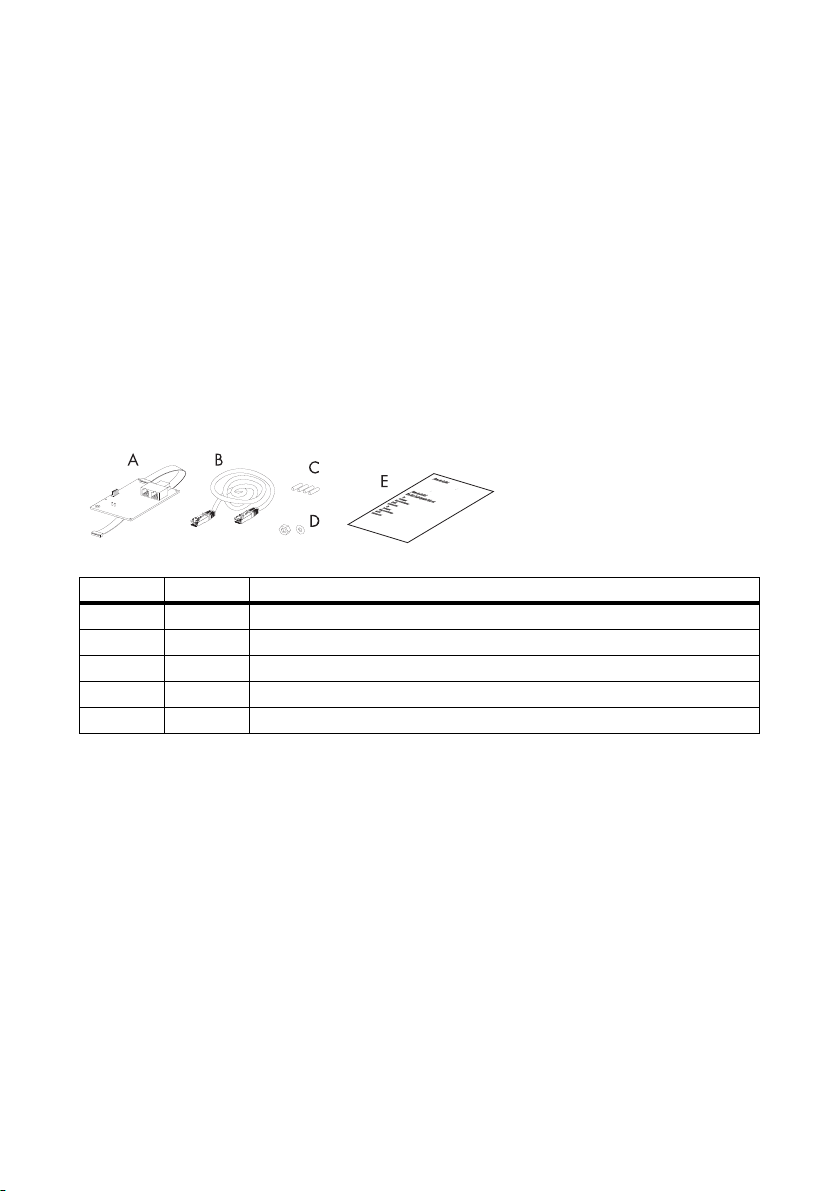
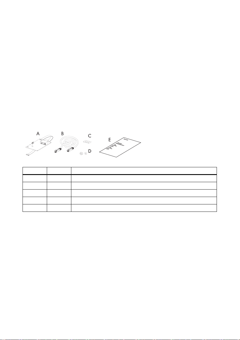
Lieferumfang
Objekt Anzahl Beschreibung
A1SIC-PB
B 1 RJ45-Kabel (5 m)
C4Befestigungsbolzen
D 1 M4-Kontaktscheibe und Mutter
E 1 Installationsanleitung
Installationsanleitung 1/4 SIC-PB-IDE083510
Page 3

SMA Solar Technology AG
Montage
GEFAHR!
Lebensgefahr durch hohe Spannungen im Sunny Island Charger.
• Alle Arbeiten am SIC-PB und am Sunny Island Charger dürfen ausschließlich durch
eine ausgebildete Elektrofachkraft ausgeführt werden.
Vorgehensweise für die Montage
GEFAHR!
Lebensgefahr durch hohe Spannungen im Sunny Island Charger.
• Leitungsschutzschalter ausschalten und gegen Wiedereinschalten sichern.
• Spannungsfreiheit feststellen.
1. Schrauben des Gehäusedeckels lösen und zur Seite legen.
2. Gehäusedeckel etwas nach vorne ziehen.
3. PE-Verbindung vom Gehäusedeckel trennen.
4. Stecker der Vielfarben-LED vorsichtig aus der Buchse „LED“ im Sunny Island Charger ziehen.
5. Gehäusedeckel abnehmen und zur Seite legen.
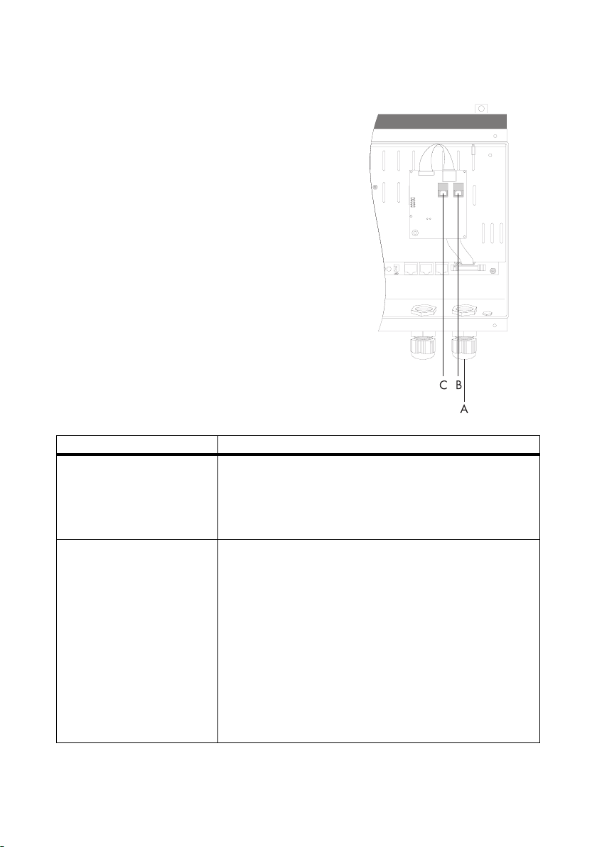
6. Beiliegende Bolzen in die vier Löcher im Bereich A
stecken.
7. Kommunikationsschnittstelle positionieren und
Flachbandkabel für den Anschluss unter der
Kommunikationsschnittstelle zur Buchse (B) führen.
8. Kommunikationsschnittstelle auf die Bolzen ste cken,
bis sie hörbar einrastet.
9. Kommunikationsschnittstelle erden. Beiliegende
M4-Kontaktscheibe und -Mutter an dem
Schraubbolzen festdrehen.
10. Flachbandkabel an der Klemme am Schirmblech
fixieren.
11. Flachbandkabel mit der rot markierten Seite nach
rechts fest in die Buchse stecken, bis es hörbar
einrastet.
Installationsanleitung 2/4 SIC-PB-IDE083510
Page 4
SMA Solar Technology AG
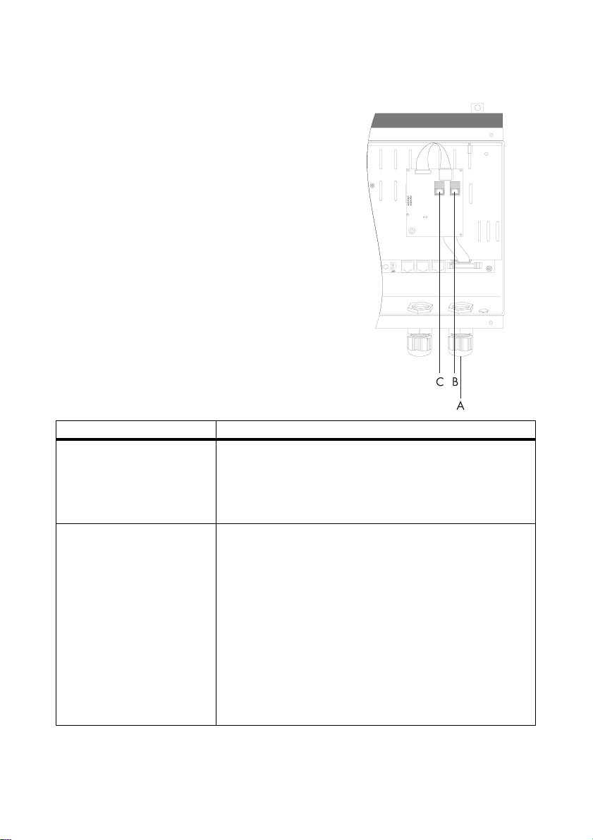
Elektrischer Anschluss
1. Überwurfmutter der Kabelverschraubung mit
metrischem Gewinde (A) abdrehen und über die
Leitung der Kommunikationsschnittstelle
(beigelegtes RJ45-Kabel) führen.
2. Dichtungseinsatz aus der Kabelverschraubung
ziehen und Blindstopfen entfernen.
3. Leitung der Kommunikationsschnittstelle durch eine
Kabeldurchführung im Dichtungseinsatz führen.
4. Dichtungseinsatz mit der Leitung der
Kommunikationsschnittstelle in die
Kabelverschraubung stecken.
5. Leitung der Kommunikationsschnittstelle durch die
Kabelverschraubung ins Innere des Sunny Island
Charger ziehen und in eine RJ45-Buchse (B) der
Kommunikationsschnittstelle stecken.
6. Terminierungsstecker in die freie RJ45-Buchse (C)
der Kommunikationsschnittstelle stecken.
Wenn... Dann...
ein Sunny Island Charger im
System angeschlossen wird...
mehrere Sunny Island Charger
im System angeschlossen
werden...
1. Leitung der Kommuniktionsschnittstelle vom Sunny Island
Charger zum Sunny Island führen und in die „ComSyncIn“Buchse/“Sync IN“-Buchse im Sunny Island stecken.
2. Terminierungsstecker in die „ComSyncOut“-Buchse/“Sync
OUT“-Buchse im Sunny Island stecken.
1. Leitung der Kommunikationsschnittstelle vom ersten Sunny
Island Charger zum nächsten Sunny Island Charger (in
diesem Fall der zweite Sunny Island Charger) führen und in
eine RJ45-Buchse der Kommunikationsschnittstelle stecken.
2. Für den Anschluss weiterer Sunny Island Charger genauso
verfahren, wie für die ersten beiden Sunny Island Charger.
3. Leitung der Kommuniktionsschnittstelle vom letzten Sunny
Island Charger zum Sunny Island führen und in die
„ComSyncIn“-Buchse/“Sync IN“-Buchse im Sunny Island
stecken.
4. Terminierungsstecker in die „ComSyncOut“-Buchse/“Sync
OUT“-Buchse im Sunny Island stecken.
Installationsanleitung 3/4 SIC-PB-IDE083510
Page 5

SMA Solar Technology AG
Die in diesen Unterlagen enthaltenen Informationen sind Eigentum der SMA Solar Technology AG. Die Veröffentlichung, ganz
ode r in T eilen , beda rf de r schr iftlich en Zus timm ung de r SMA Sol ar Technology AG. Eine innerbetriebliche Vervielfältigung, die zur
Evaluierung des Produktes oder zum sachgemäßen Einsatz bestimmt ist, ist erlaubt und nicht genehmigungspflichtig.
Haftungsausschluss
Es gelten als Grundsatz die Allgemeinen Lieferbedingungen der SMA Solar Technology AG.
Der Inhalt dieser Unterlagen wird fortlaufend überprüft und gegebenenfalls angepasst. Trotzdem können Abweichungen nicht
ausgeschlossen werden. Es wird keine Gewähr für Vollständigkeit gegeben. Die jeweils aktuelle Version ist im Internet unter
www.SMA.de abrufbar oder über die üblichen Vertriebswege zu beziehen.
Gewährleistungs- und Haftungsansprüche bei Schäden jeglicher Art sind ausgeschlossen, wenn sie auf eine oder mehrere der
folgenden Ursachen zurückzuführen sind:
• Transportschäden
• Unsachgemäße oder nicht bestimmungsgemäße Verwendung des Produkts
• Betreiben des Produkts in einer nicht vorgesehenen Umgebung
• Betreiben des Produkts unter Nichtberücksichtigung der am Einsatzort relevanten gesetzlichen Sicherheitsvorschriften
• Nichtbeachten der Warn- und Sicherheitshinweise in allen für das Produkt relevanten Unterlagen
• Betreiben des Produkts unter fehlerhaften Sicherheits- und Schutzbedingungen
• Eigenmächtiges Verändern oder Reparieren des Produkts oder der mitgelieferten Software
• Fehlverhalten des Produkts durch Einwirkung angeschlossener oder benachbarter Geräte außerhalb der gesetzlich zulässigen
Grenzwerte
• Katastrophenfälle und höhere Gewalt
Die Nutzung der mitgelieferten von der SMA Solar Technology AG hergestellten Software unterliegt zusätzlich den folgenden
Bedingungen:
• Die SMA Solar Technology AG lehnt jegliche Haftung für direkte oder indirekte Folgeschäden, die sich aus der Verwendung
der von SMA Solar Technology AG erstellten Software ergeben, ab. Dies gilt auch für die Leistung beziehungsweise NichtLeistung von Support-Tätigkeiten.
• Mitgelieferte Software, die nicht von der SMA Solar Technology AG erstellt wurde, unterliegt den jeweiligen Lizenz- und
Haftungsvereinbarungen des Herstellers.
SMA-Werksgarantie
Die aktuellen Garantiebedingungen liegen Ihrem Gerät bei. Bei Bedarf können Sie diese auch im Internet unter www.SMA.de
herunterladen oder über die üblichen Vertriebswege in Papierform beziehen.
Warenzeichen
Alle Warenzeichen werden anerkannt, auch wenn diese nicht gesondert gekennzeichnet sind. Fehlende Kennzeichnung bedeutet
nicht, eine Ware oder ein Zeichen seien frei.
SMA Solar Technology AG
Sonnenallee 1
34266 Niestetal
Deutschland
Tel. +49 561 9522-0
Fax +49 561 9522-100
www.SMA.de
E-Mail: info@SMA.de
© 2004 bis 2008 SMA Solar Technology AG. Alle Rechte vorbehalten.
Installationsanleitung 4/4 SIC-PB-IDE083510
Page 6

SMA Solar Technology AG
SIC-PB
Communication Interface for Sunny Island Charger
The SIC-PB is a communication interface for the Sunny Island Charger. It enables communication
between the Sunny Island Charger and the Sunny Island used. Thanks to the SIC-PB, the Sunny Island
Charger is ideally integrated into the Sunny Island operation control.
Notes on this Manual
• The manual describes how to install the SIC-PB.
• This manual applies to the SIC-PB communication interface.
• This manual is intended for the installer.
Packing List
Object Quantity Description
A1SIC-PB
B 1 RJ45 cable (5 m)
C4Mounting bolts
D1M4 contact disk and nut
E 1 Installation guide
Installation Guide 1/4 SIC-PB-IEN083510
Page 7

SMA Solar Technology AG
Mounting
DANGER!
Danger to life due to high voltages in the Sunny Island Charger.
• All work on the SIC-PB and the Sunny Island Charger must only be performed by a
qualified electrician.
Mounting Procedure
DANGER!
Danger to life due to high voltages in the Sunny Island Charger.
• Switch off the line circuit breaker and secure it to prevent it from being reactivated.
• Ensure that no voltage is present in the system.
1. Unscrew the housing cover screws and set them aside.
2. Pull the cover slightly forward.
3. Disconnect the PE connection from the cover.
4. Carefully remove the multicolored LED from the "LED" socket in the Sunny Island Charger.
5. Remove the cover and set it aside.
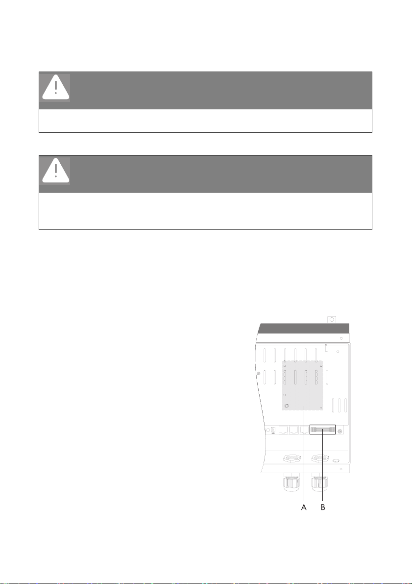
6. Insert the bolts provided in the four holes in section
A.
7. Position the communication interface and route the
ribbon cable for the connection under the
communication interface to the socket (B).
8. Insert the communication interface on the bolts until
it audibly clicks into place.
9. Ground the communication interface. Tighten the
M4 contact disk and nut on the bolt.
10. Attach the ribbon cable to the terminal at the shield
plate.
11. Securely insert the ribbon cable with the side
marked in red on the right into the socket until it
audibly clicks into place.
Installation Guide 2/4 SIC-PB-IEN083510
Page 8
SMA Solar Technology AG
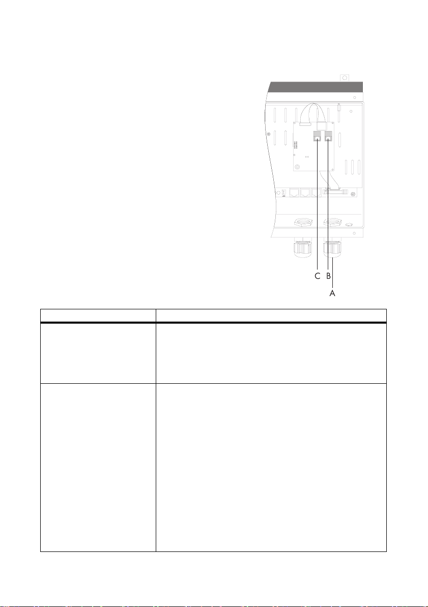
Electrical Connection
1. Remove the metric-thread cable screw
connectionslocknut(A)andslideitoverthecommunica
tioninterfacecable(RJ45cableprovided).'
2. Remove the seal insert from the cable screw
connection and remove the dummy plug.
3. Route the communication interface cable through a
cable opening in the seal insert.
4. Insert the seal insert along with the communication
interface cable into the cable screw connection.
5. Route the communication interface cable through
the cable screw connection into the inside of the
Sunny Island Charger and insert it into a RJ45
socket (B) of the communication interface.
6. Insert a termination connector into the open RJ45
socket (C) of the communication interface.
If... Then...
one Sunny Island Charger is
connected to the system...
several Sunny Island Chargers
are connected to the system...
1. Route the communication interface cable of the Sunny Island
Charger to the Sunny Island and insert it into the
"ComSyncIn" socket/"Sync IN" socket in the Sunny Island.
2. Insert a termination connector in the "ComSyncOut" socket/
"SyncOUT" socket in the Sunny Island.
1. Route the communication interface cable from the first Sunny
Island Charger to the next Sunny Island Charger (in this
case, the second Sunny Island Charger) and insert it into a
RJ45 socket of the communication interface.
2. Follow the same procedure for the first two Sunny Island
Charger devices to connect additional Sunny Island
Charger devices.
3. Route the communication interface cable from the last Sunny
Island Charger to the Sunny Island and insert it into the
"ComSyncIn" socket/"Sync IN" socket in the Sunny Island.
4. Insert a termination connector in the "ComSyncOut" socket/
"SyncOUT" socket in the Sunny Island.
Installation Guide 3/4 SIC-PB-IEN083510
Page 9

SMA Solar Technology AG
The information contained in this document is the property of SMA Solar Technology AG. Publishing its content, either partially or
in full, requires the written permission of SMA Solar Technology AG. Any internal company copying of the document for the
purposes of evaluating the product or its correct implementation is allowed and does not require permission.
Exclusion of liability
The general terms and conditions of delivery of SMA Solar Technology AG shall apply.
The content of these documents is continually checked and amended, where necessary. However, discrepancies cannot be
excluded. No guarantee is made for the completeness of these documents. The latest version is available online at www.SMA.de
or from the usual sales channels.
Guarantee or liability claims for damages of any kind are excluded if they are caused by one or more of the following:
• Damages during transportation
• Improper or inappropriate use of the product
• Operating the product in an unintended environment
• Operating the product whilst ignoring relevant, statutory safety regulations in the deployment location
• Ignoring safety warnings and instructions contained in all documents relevant to the product
• Operating the product under incorrect safety or protection conditions
• Altering the product or supplied software without authority
• The product malfunctions due to operating attached or neighboring devices beyond statutory limit values
• In case of unforeseen calamity or force majeure
The use of supplied software produced by SMA Solar Technology AG is subject to the following conditions:
• SMA Solar Technology AG rejects any liability for direct or indirect damages arising from the use of software developed by
SMA Solar Technology AG. This also applies to the provision or non-provision of support activities.
• Supplied software not developed by SMA Solar Technology AG is subject to the respective licensing and liability agreements
of the manufacturer.
SMA Factory Warranty
The current guarantee conditions come enclosed with your device. These are also available online at www.SMA.de and can be
downloaded or are available on paper from the usual sales channels if required.
Trademarks
All trademarks are recognized even if these are not marked separately. Missing designations do not mean that a product or brand
is not a registered trademark.
SMA Solar Technology AG
Sonnenallee 1
34266 Niestetal
Germany
Tel. +49 561 9522-0
Fax +49 561 9522-100
www.SMA.de
E-Mail: info@SMA.de
© 2004 to 2008 SMA Solar Technology AG. All rights reserved
Installation Guide 4/4 SIC-PB-IEN083510
Page 10

SMA Solar Technology AG
SIC-PB
Interfaz de comunicación para Sunny Island Charger
El SIC-PB es una interfaz de comunicación para el Sunny Island Charger. Su función es comunicar el
Sunny Island Charger con el Sunny Island utilizado. Así se integra de forma óptima el Sunny Island
Charger en la gestión operativa del Sunny Island.
Indicaciones para el uso de estas instrucciones
En estas instrucciones se describe la instalación del SIC-PB.
Estas instrucciones son válidas para la interfaz de comunicación SIC-PB.
Estas instrucciones van dirigidas al instalador.
Contenido de la entrega
Artículo Cantidad Descripción
A1SIC-PB
B 1 Cable RJ45 (5 m)
C 4 Pernos de fijación
D 1 Arandela de contacto M4 y tuerca
E 1 Instrucciones de instalación
Instrucciones de instalación 1/4 SIC-PB-IES083510
Page 11

SMA Solar Technology AG
Montaje
PELIGRO!
¡Peligro de muerte por altas tensiones en el Sunny Island Charger!
¡T odo s los tr aba jos en el SI C-P B y e n el Su nny Isl and Cha rge r deberán ser realizados
exclusivamente por electricistas cualificados!
Procedimiento para el montaje
PELIGRO!
¡Peligro de muerte por altas tensiones en el Sunny Island Charger!
Desconecte el interruptor automático y asegúrelo contra reconexión accidental.
Compruebe que no haya tensión.
1. Suelte los tornillos de la tapa de la carcasa y póngalos a un lado.
2. Tire la tapa de la carcasa ligeramente hacia adelante.
3. Desconecte la toma a tierra (PE) de la tapa de la carcasa.
4. Extraiga el conector del LED de múltiples colores cuidadosamente del conector hembra "LED"
del Sunny Island Charger.
5. Extraiga la tapa de la carcasa y póngala a un lado.
6. Introduzca los pernos incluidos en los cuatro
agujeros de la zona A.
7. Coloque la interfaz de comunicación y tienda el
cable plano para la conexión debajo de la interfaz
de comunicación hacia el conector hembra (B).
8. Introduzca la interfaz de comunicación por los
pernos hasta que quede insertada de manera
audible.
9. Ponga a tierra la interfaz de comunicación. Apriete
la ara nde la de co nta cto M4 y la t uer ca i ncl uid as al
perno atornillable.
10. Fije el cable plano al borne de la chapa de
protección.
11. Introduzca el cable plano con el lado marcado de
color rojo hacia la derecha en el conector hembra
hasta que enganche de forma audible.
Instrucciones de instalación 2/4 SIC-PB-IES083510
Page 12

SMA Solar Technology AG
Conexión eléctrica
1. Desenrosque la tuerca de unión del racor
atornillado para cables con rosca métrica (A) y
hágala pasar por el cable de la interfaz de
comunicación (cable RJ45 adjunto).
2. Extraiga la junta del racor atornillado para cables
y retire el tapón obturador.
3. Tienda el cable de la interfaz de comunicación a
través de una boquilla de paso en la junta.
4. Introduzca la junta con el cable de la interfaz de
comunicación dentro del racor atornillado para
cables.
5. Haga pasar el cable de la interfaz de
comunicación a través del racor atornillado para
cables por el interior del Sunny Island Charger y
conéctela a un conector hembra RJ45 (B) de la
interfaz de comunicación.
6. Conecte el conector de terminación al conector
hembra RJ45 libre (C) de la interfaz de
comunicación.
Si Entonces
se conecta un Sunny Island
Charger en el sistema...
se conectan varios Sunny Island
Charger en el sistema...
1. Tienda el cable de la interfaz de comunicación del Sunny
Island Charger hacia el Sunny Island y enchúfelo en el
conector hembra "ComSyncIn"/"Sync IN" en el Sunny
Island.
2. Conecte el conector de terminación en el conector hembra
"ComSyncOut"/"SyncOUT" en el SunnyIsland.
1. Tienda el cable de la interfaz de comunicación del primer
Sunny Island Charger hacia el próximo Sunny Island
Charger (en este caso, el segundo Sunny Island Charger) y
conéctelo a un conector hembra RJ45 de la interfaz de
comunicación.
2. Para la conexión de otros Sunny Island Charger proceda
del mismo modo que con los primeros dos Sunny Island
Charger.
3. Tienda el cable de la interfaz de comunicación del último
Sunny Island Charger hacia el Sunny Island y enchúfelo en
el conector hembra "ComSyncIn"/"Sync IN" en el Sunny
Island.
4. Conecte el conector de terminación en el conector hembra
"ComSyncOut"/"SyncOUT" en el Sunny Island.
Instrucciones de instalación 3/4 SIC-PB-IES083510
Page 13

SMA Solar Technology AG
Las informaciones contenidas en esta documentación son propiedad de SMA Solar Technology AG. La publicación, completa o
parcial, requiere el consentimiento por escrito de SMA Solar Technology AG. La reproducción interna por parte de una empresa
con vistas a evaluar el producto o emplearlo correctamente está permitida y no requiere autorización.
Exención de responsabilidad
Rigen por principio las condiciones generales de entrega de SMA Solar Technology AG.
El contenido de esta documentación se revisa y actualiza periódicamente. No obstante, no se excluyen posibles divergencias.
No garantizamos la integridad de la información contenida en este documento. La versión actual en cada momento puede
consultarse en la página www.SMA.de o solicitarse a través de las habituales vías comerciales.
Quedan excluidos en todos los casos las reclamaciones de garantía y de responsabilidad, si se deben a una o varias de las
siguientes causas:
• Daños de transporte
• Uso indebido del producto o no conforme a la finalidad por la que ha sido desarrollado
• Uso del producto en un entorno no previsto
• Uso del producto incumpliendo las normas de seguridad legales aplicables en el lugar de trabajo
• Incumplimiento de las indicaciones de seguridad y advertencias descritas en todos los documentos relevantes del producto
• Uso del producto bajo condiciones de seguridad y protección deficientes
• Modificación por cuenta propia o reparación del producto o del software suministrado
• Comportamiento incorrecto del producto por influencia de otros aparatos conectados o muy cercanos que superen los valores
límites legalmente permitidos
• Casos de catástrofes o de fuerza mayor
La utilización del software desarrollado por SMA Solar Technology AG está sujeta a las siguientes condiciones adicionales:
• SMA Solar Technology AG rechaza cualquier responsabilidad para daños sucesivos directos o indirectos causados por la
utilización del software desarrollado por SMA Solar Technology AG. Esto también se aplica en el caso de prestaciones o noprestaciones de asistencia.
• El software suministrado no desarrollado por SMA Solar Technology AG está sujeto a los correspondientes acuerdos de
licencia y responsabilidad de su fabricante.
Garantía de fábrica de SMA
Las condiciones actuales de garantía están incluidos en el suministro de su aparato. También pueden descargarse en la página
www.SMA.de o solicitarse a través de las habituales vías comerciales.
Marcas registradas
Se reconocen todas las marcas registradas, incluso si no están señaladas por separado. Las faltas de señalización no implican
que la mercancía o las marcas sean libres.
SMA Solar Technology AG
Sonnenalle 1
34266 Niestetal
Alemania
Tel. +49 561 9522-0
Fax +49 561 9522-100
www.SMA.de
Correo electrónico: info@SMA.de
© 2004 - 2008 SMA Solar Technology AG.. Reservados todos los derechos.
Instrucciones de instalación 4/4 SIC-PB-IES083510
Page 14
SMA Solar Technology AG
SIC-PB
Interface de communication pour Sunny Island Charger
Le SIC-PB est une interface de communication pour le Sunny Island Charger. Il permet de
communiquer entre le Sunny Island Charger et le Sunny Island utilisé. Grâce à lui, le Sunny Island
Charger est intégré de façon optimale dans la gestion de l'exploitation du Sunny Island.
Remarques relatives à ce guide d'installation
• Ce guide d'installation décrit l'installation du SIC-PB.
• Ce guide d'installation est uniquement valable pour l'interface de communication SIC-PB.
• Ce guide s'adresse aux installateurs.
Contenu de la livraison
Objet Quantité Description
A1SIC-PB
B1Câble RJ45 (5m)
C 4 Boulon de fixation
D 1 Rondelle de contact M4 et écrou
E 1 Guide d'installation
Instructions d’installation 1/4 SIC-PB-IFR083510
Page 15

SMA Solar Technology AG
Montage
DANGER !
Haute tension dans le Sunny Island Charger. Danger de mort !
• T out e in ter ven tio n su r le SIC- PB e t su r le Sun ny I sla nd C har ger doit être exclusivement
effectuée par un électricien qualifié spécialisé.
Marche à suivre pour le montage
DANGER !
Haute tension dans le Sunny Island Charger. Danger de mort !
• Coupez le disjoncteur et sécurisez-le contre toute remise en marche involontaire.
• Vérifiez l'état hors tension.
1. Dévissez le couvercle du boîtier et mettez les vis de côté.
2. Tirez légèrement vers l'avant le couvercle du boîtier.
3. Déconnectez le raccordement PE du couvercle du boîtier.
4. Retirez délicatement le connecteur mâle de la DEL multicolore du con nec teu r fe mel le « DE L » du
Sunny Island Charger.
5. Retirez le couvercle du boîtier et mettez-le de côté.
6. Insérez les boulons livrés dans les quatre trous de
la zone A.
7. Positionnez l'interface de communication et insérez
le câble plat de raccordement dans le connecteur
(B) situé sous l'interface de communication.
8. Placez l'interface de communication sur les boulons
jusqu'à entendre un clic d'enclenchement.
9. Mettez l'interface de communication à la terre.
Vissez fermement la rondelle de contact et l'écrou
M4 sur le boulon fileté.
10. Fixez le câble plat à la borne située sur la tôle de
protection.
11. Enfoncez le câble plat, côté en rouge à droite, dans
le connecteur jusqu'à entendre un clic
d'enclenchement.
Instructions d’installation 2/4 SIC-PB-IFR083510
Page 16
SMA Solar Technology AG
Raccordement électrique
1. Desserrez l'écrou d'accouplement du passe-câble à
vis à filetage métrique (A) et passez-le sur le câble
de l'interface de communication (câble RJ45 livré).
2. Ret ire z l'ins ert d'é tanché ité du p resse- étoupe et ôtez
le tampon borgne.
3. Introduisez le câble de l'interface de
communication dans l'insert d'étanchéité à travers
un passage de câble.
4. Enfoncez l'insert d'étanchéité et le câble de
l'interface de communication dans l e passe-c âble à
vis.
5. Tirez le câble de l'interface de communication par
le passe-câble à vis à l'intérieur du Sunny Island
Charger et branchez-le sur l'un des connecteurs
RJ45 (B) de l'interface de communication.
6. Enfichez le connecteur de terminaison dans le
connecteur RJ45 non occupé (C) de l'interface de
communication.
Si... Alors...
un seul Sunny Island Charger est
raccordé dans le système...
plusieurs Sunny Island Charger
sont raccordés dans le
système...
1. Ram ene z le câb le d e l' int erf ace de c omm uni cat ion du S unn y
Island Charger au Sunny Island et enfichez-le sur le
connecteur « ComSyncIn »/« Sync IN » du Sunny Island.
2. Enfichez le connecteur de terminaison dans le connecteur
« ComSyncOut »/« Sync OUT » du Sunny Island.
1. Faites passer le câble de l'interface de communication du
premier Sunny Island Charger au Sunny Island Charger
suivant (dans ce cas, le deuxième Sunny Island Charger) et
enfichez-le à l'un des connecteurs RJ45 (B) de l'interface de
communication.
2. Procédez de la même manière que pour les deux premiers
Sunny Island Charger pour raccorder d'autres Sunny Island
Charger.
3. Ramenez le câble de l'interface de communication du
dernier Sunny Island Charger au Sunny Island et enfichez-le
sur le connecteur «ComSyncIn»/«Sync IN» du Sunny
Island.
4. Enfichez le connecteur de terminaison dans le connecteur
« ComSyncOut »/« Sync OUT » du Sunny Island.
Instructions d’installation 3/4 SIC-PB-IFR083510
Page 17

SMA Solar Technology AG
Les informations figurant dans ces documents sont la propriété exclusive de SMA Solar Technology AG. La publication de ces
informations en totalité ou en partie doit être soumise à l'accord préalable de SMA Solar Technology AG. Une reproduction
interne au profit de l'entreprise, pour l'évaluation et la mise en service conforme du produit est autorisée sans accord préalable.
Clause de non-responsabilité
En principe, les conditions générales de livraison de SMA Solar Technology AG s'appliquent.
Le contenu de ces documents est régulièrement contrôlé et, le cas échéant, adapté. Des divergences ne peuvent néanmoins être
exclues. L’exhaustivité des documents n’est pas garantie. La version actuellement en vigueur peut être consultée sur le site Internet
www.SMA.de ou être obtenue par les réseaux de distribution habituels.
Aucune garantie ni responsabilité ne s’applique lors de dommages quels qu’ils soient, si ceux-ci sont dus à une ou plusieurs des
causes suivantes :
• Transport incorrect
• Utilisation du produit inappropriée ou non conforme aux instructions d’utilisation
• Emploi du produit dans un environnement non prévu
• Emploi du produit sans prise en compte des dispositions légales de sécurité pertinentes sur le lieu d’utilisation
• Non-respect des consignes d’alarme et de sécurité décrites dans l’ensemble de la documentation pertinente du produit
• Emploi du produit dans de mauvaises conditions de sécurité et de protection
• Modification arbitraire ou réparation du produit ou du logiciel livré conjointement
• Dysfonctionnement du produit dû à l’influence d’un appareil branché ou placé à proximité hors des limites autorisées
• Catastrophe ou cas de force majeure
L’utilisation des logiciels livrés et créés par SMA Solar Technology AG est aussi soumise aux conditions suivantes :
• La SMA Solar Technology AG décline toute responsabilité quant aux dommages découlant directement ou indirectement de
l’utilisation du logiciel fabriqué par SMA Solar Technology AG. Ceci s’applique également à la prestation ou au défaut de
prestation de services d’après-vente
• Le logiciel livré conjointement, qui n’a pas été créé par SMA Solar Technology AG, est soumis aux accords de licence et de
responsabilité correspondants du fabricant.
Garantie usine SMA
Les conditions de garantie actuelles sont livrées avec votre appareil. Vous pouvez également, si besoin est, les télécharger sur le
site Internet www.SMA.de ou les obtenir sous forme papier par le par les réseaux de distribution habituels.
Marque déposée
Toutes les marques déposées sont reconnues, y compris lorsqu’elles ne sont pas mentionnées expressément. L'absence de
l'emblème de marque ne signifie pas qu'un produit ou une marque puisse être librement commercialisé.
SMA Solar Technology AG
Sonnenallee 1
34266 Niestetal
Allemagne
Tél. +49 561 9522-0
Fax +49 561 9522-100
www.SMA.de
e-mail : info@SMA.de
© 2004 à 2008 SMA Solar Technology AG. Tous droits réservés.
Instructions d’installation 4/4 SIC-PB-IFR083510
Page 18

SMA Solar Technology AG
SIC-PB
Interfaccia di comunicazione per Sunny Island Charger
SIC-PB è un interfaccia di comunicazione per Sunny Island Charger. Serve per la comunicazione fra
il Sunny Island Charger e il Sunny Island utilizzato, grazie al quale il Sunny Island Charger viene
integrato in modo ottimale nella conduzione del Sunny Island.
Avvertenze sullimpiegodiquestomanuale'
• Questo manuale illustra linstallazionedelSIC-PB.'
• Questo manuale vale per linterfacciadicomunicazioneSIC-PB.'
• Il presente manuale è destinato allinstallatore.'
Fornitura
Oggetto Numero Descrizione
A1SIC-PB
B 1 Cavo RJ45 (5 m)
C 4 Bulloni di fissaggio
D 1 Rondella di contatto M4 e dado
E 1 Istruzioni per linstallazione'
Istruzioni per’installazione 1/5 SIC-PB-IIT083510
Page 19

SMA Solar Technology AG
Montaggio
PERICOLO!
Pericolo di morte a causa di alte tensioni nel Sunny Island Charger.
• Tutti i lavori al SIC-PB e al Sunny Island Charger possono essere eseguiti
esclusivamente da un elettricista qualificato.
Procedura per il montaggio
PERICOLO!
Pericolo di morte a causa di alte tensioni nel Sunny Island Charger.
• Disinserire gli interruttori di protezione di linea e adottare provvedimenti contro la
riaccensione involontaria.
• Controllare la disinserzione della tensione.
1. Svitare le viti del coperchio dellinvolucroemetterledaparte.'
2. Tirare il coperchio dellinvolucrounpo'inavanti.'
3. Staccare il collegamento PE dal coperchio dellinvolucro.'
4. Staccare con cautela il connettore del LED multicolore dalla presa "LED" del Sunny Island
Charger.
5. Togliere il coperchio dellinvolucroemetterlodaparte.'
6. Inserire i bulloni in dotazione nei quattro fori della
sezione A.
7. Posizionare
linterfacciadicomunicazioneeinfilarelapiattinamulti
polarenellapresa(B)perilcollegamentosottol'interfa
cciadicomunicazione.'
8. Inserire
linterfacciadicomunicazionesuibullonifinoalloscatt
o.'
9. Mettere a terra
linterfacciadicomunicazione.Stringerelarondelladi
contattoM4eildadoindotazioneconibullone.'
Istruzioni per’installazione 2/5 SIC-PB-IIT083510
Page 20

SMA Solar Technology AG
10. Fissare la piattina multipolare al morsetto sulla
lamiera di schermatura.
11. Inserire la piattina multipolare nella presa tenendo
a destra il lato contrassegnato in rosso, fissandola
fino a sentirne lo scatto.
Collegamento elettrico
1. Svitare il dado del pressacavo con filetto metrico
(A) e sfilarlo lungo il cavo
dellinterfacciadicomunicazione(cavoRJ45indotazi
one).'
2. Sfilare la guarnizione dal pressacavo e togliere il
tappo cieco.
3. Infilare il cavo
dellinterfacciadicomunicazionenellaguarnizioneatt
raversounpassacavo.'
4. Inserire la guarnizione con il cavo
dellinterfacciadicomunicazionenelpressacavo.'
5. Tirare il cavo
dellinterfacciadicomunicazioneattraversoilpressac
avoall'internodel'Sunny Island Charger e inserirlo
in una presa RJ45 (B)
dellinterfacciadicomunicazione.'
6. Inserire il connettore di terminazione nella presa
libera RJ45 (C) dellinterfacciadicomunicazione.'
Istruzioni per’installazione 3/5 SIC-PB-IIT083510
Page 21

SMA Solar Technology AG
Se... Allora...
si collega un Sunny Island
1. Portare il cavo dellinterfacciadicomunicazionedal'Sunny
Charger al sistema...
2. Inserire il connettore di terminazione nella presa
si coll egan o div ersi Sunn y Isl and
1. Portare il cavo
Charger al sistema...
2. Per collegare ulteriori Sunny Island Charger procedere allo
3. Portare il cavo
4. Inserire il connettore di terminazione nella presa
Island Charger al Sunny Island e inserirlo nella presa
„ComSyncIn“/“Sync IN“ del Sunny Island.
"ComSyncOut"/"Sync OUT" del Sunny Island.
dellinterfacciadicomunicazionedalprimo'Sunny Island
Charger al successivo Sunny Island Charger (in questo caso
il secondo Sunny Island Charger) ed inserirlo in una presa
RJ45 dellinterfacciadicomunicazione.'
stesso modo, come con i primi due Sunny Island Charger.
dellinterfacciadicomunicazionedall'ultimo'Sunny Island
Charger al Sunny Island e inserirlo nella presa
„ComSyncIn“-Buchse/“Sync IN“ del Sunny Island.
"ComSyncOut"/"Sync OUT" del Sunny Island.
Istruzioni per’installazione 4/5 SIC-PB-IIT083510
Page 22

SMA Solar Technology AG
Le informazioni contenute in questa documentazione sono proprietà della SMA Solar Technology AG. Per la pubblicazione,
integrale o parziale, è necessario il consenso scritto della SMA Solar Technology AG. La riproduzione per scopi interni
all'azienda, destinata alla valutazione del prodotto o al suo utilizzo corretto, è consentita e non è soggetta ad approvazione.
Esonero di responsabilità
Come principio valgono le Condizioni Generali di Fornitura della SMA Solar Technology AG.
Il contenuto della presente documentazione viene verificato di continuo e se necessario adattato. Non possono tuttavia essere
escluse divergenze. Non può essere data alcuna garanzia di completezza. La versione aggiornata è richiamabile in Internet sul
sito www.SMA.de oppure può essere ordinata attraverso i normali canali di distribuzione.
Sono escluse rivendicazioni di garanzia e di responsabilità in caso di danni di ogni genere qualora gli stessi siano riconducibili
ad una o ad alcune delle seguenti cause:
• danni dovuti al trasporto,
• utilizzo improprio del prodotto oppure non conforme alla sua destinazione,
• impiego del prodotto in un ambiente non previsto,
• impiego del prodotto senza tener conto delle norme di sicurezza legali rilevanti nel luogo d'impiego,
• mancata osservanza delle indicazioni di avvertimento e di sicurezza riportate in tutte le documentazioni essenziali per il
prodotto,
• impiego del prodotto in condizioni di sicurezza e di protezione errate,
• modifica o riparazione arbitraria del prodotto e del software fornito,
• funzionamento errato del prodotto dovuto all'azione di apparecchi collegati o adiacenti al di fuori dei valori limite ammessi
per legge,
• catastrofi e forza maggiore.
L'utilizzo del software in dotazione prodotto dalla SMA Solar Technology AG è sottoposto inoltre alle seguenti condizioni:
• La SMA Solar Technology AG non si assume alcuna responsabilità per danni diretti o indiretti determinati dall'impiego del
software prodotto dalla SMA Solar Technology AG, ciò si applica anche alla prestazione o non-prestazione di attività di
assistenza.
• Il software fornito che non sia stato prodotto dalla SMA Solar Technology AG è soggetto ai relativi accordi di licenza e di
responsabilità del produttore.
Garanzia di fabbrica SMA
Le attuali condizioni di garanzia sono allegate al vostro apparecchio. In caso di necessità, è possibile scaricarle dal sito Internet
www.SMA.de o ottenerle in formato cartaceo attraverso i normali canali di distribuzione.
Marchio
Tutti i marchi sono validi anche se gli stessi non sono contrassegnati separatamente. L'assenza di contrassegno non significa che
un prodotto o un marchio non siano registrati.
SMA Solar Technology AG
Sonnenallee 1
34266 Niestetal
Germania
Tel. +49 561 9522-0
Fax +49 561 9522-100
www.SMA.de
E-Mail: info@SMA.de
© 2004-2008 SMA Solar Technology AG. Tutti i diritti riservati.
Istruzioni per’installazione 5/5 SIC-PB-IIT083510
Page 23

SMA Solar Technology AG
SIC-PB
Διεπαφή επικοινωνίας για τον φορτιστή Sunny Island
H SIC-PB είναι μια διεπαφή επικοινωνίας για τον φορτιστή Sunny Island. Εξυπηρετεί την επικοινωνία
μεταξύ του φορτιστή και του μετατροπέα Sunny Island. Χάρη στην εν λόγω διεπαφή, συνδέεται
ιδανικά ο φορτιστής Sunny Island στη συσκευή.
Οδηγίες σχετικά με το εγχειρίδιο
• Στο παρόν εγχειρίδιο περιγράφεται η εγκατάσταση της SIC-PB.
• Το παρόν εγχειρίδιο ισχύει για τη διεπαφή SIC-PB.
• Το παρόν εγχειρείδιο απευθύνεται στον τεχνικό εγκατάστασης
Παραδιδόμενος εξοπλισμός
Αντικείμενο Αριθμός Περιγραφή
A1SIC-PB
B 1 Καλώδιο RJ45 μήκους 5m
C4Μπουλόνια στήριξης
D 1 Δίσκος επαφής M4 και περικόχλια
Ε 1 Οδηγίες τοποθέτησης
Οδηγίες τοποθέτησης 1/5 SIC-PB-IGR083510
Page 24
SMA Solar Technology AG
Συναρμολόγηση
ΚΙΝΔΥΝΟΣ!
Κίνδυνος για τη ζωή λόγω πολύ υψηλών τάσεων στον μετατροπέα Sunny Island
Charger.
• Όλες οι εργασίες στη διεπαφή SIC-PB και στον φορτιστή Sunny Island πρέπει να
εκτελούνται μόνο από κατάλληλα εκπαιδευμένο ηλεκτρολόγο.
Τρόπος εκτέλεσης της συναρμολόγησης
ΚΙΝΔΥΝΟΣ!
Κίνδυνος για τη ζωή λόγω πολύ υψηλών τάσεων στον μετατροπέα Sunny Island
Charger.
• Απενεργοποιήστε τον διακόπτη προστασίας αγωγών και ασφαλίστε τον έναντι
επανενεργοποίησης.
• Βεβαιωθείτε ότι δεν φέρει τάση
1. Ξεβιδώνετε το καπάκι του κελύφους του μετατροπέα και το αφήνετε στην άκρη.
2. Τραβάτε το καπάκι του κελύφους προς τα εμπρός.
3. Αποχωρίζετε τη σύνδεση PE από το καπάκι του κελύφους.
4. Απομακρύνετε προσεχτικά το βύσμα της πολύχρωμης φωτοδιόδου από την υποδοχή "LED"
του φορτιστή Sunny Island.
5. Αφαιρείτε το καπάκι του κελύφους και το αφήνετε στην άκρη
6. Εισάγετε τα μπουλόνια στις 4 οπές στην περιοχή Α
7. Τοποθετείτε τη διεπαφή επικοινωνίας στη θέση της
και συνδέετε το πεπλατυσμένο καλώδιο στην
υποδοχή (Β), περνώντας το κάτω από τη διεπαφή
επικοινωνίας.
8. Εισάγετε τη διεπαφή επικοινωνίας στα μπουλόνια,
μέχρι να ακουστεί ο χαρακτηριστικός ήχος
ασφάλισης.
9. Γειώνετε τη διεπαφή επικοινωνίας. Σφίγγετε τον
δίσκο επαφής M4 και το περικόχλιο στο μπουλόνι.
Οδηγίες τοποθέτησης 2/5 SIC-PB-IGR083510
Page 25

SMA Solar Technology AG
10. Στερεώνετε το πεπλατυσμένο καλώδιο στον
συνδετήρα θωράκισης της μονάδας
11. Εισάγετε το πεπλατυσμένο καλώδιο από την
κόκκινη πλευρά σφιχτά στην υποδοχή, μέχρι να
ακουστεί ο χαρακτηριστικός ήχος ασφάλισης.
Ηλεκτρική σύνδεση
1. Ξεβιδώνετε το περικόχλιο ασφάλισης της
κοχλίωσης του καλωδίου και το περνάτε πάνω από
τον αγωγό της διεπαφής επικοινωνίας (καλώδιο
RJ45).
2. Αφαιρείτε τη στεγάνωση διέλευσης καλωδίου
καθώς και τα πώματα σφράγισης από την
κοχλίωση του καλωδίου.
3. Περνάτε τον αγωγό της διεπαφής επικοινωνίας
μέσω μιας διέλευσης καλωδίων στη στεγάνωαη.
4. Τοποθετείτε τη στεγάνωση της διέλευσης καλωδίων
μαζί με τον αγωγό της διεπαφής επικοινωνίας στην
κοχλίωση του καλωδίου.
5. Περνάτε τον αγωγό της διεπαφής επικοινωνίας
μέσα από την κοχλίωση του καλωδίου στο
εσωτερικό του φορτιστή Sunny Island και τον
εισάγετε σε μια υποδοχή RJ45 (B) της διεπαφής
επικοινωνίας.
6. Εισάγετε το τερματικό βύσμα στην ελεύθερη
υποδοχή RJ45 (C) της διεπαφής επικοινωνίας
Οδηγίες τοποθέτησης 3/5 SIC-PB-IGR083510
Page 26

SMA Solar Technology AG
Όταν... Τότε...
Ο φορτιστής Sunny Island
1. Περνάτε τον αγωγό της διεπαφής επικοινωνίας από τον
συνδέεται στο σύστημα...
2. Εισάγετε το τερματικό βύσμα στην υποδοχή
περισσότεροι φορτιστές Sunny
1. Περνάτε τον αγωγό της διεπαφής επικοινωνίας από τον
Island συνδέονται στο
σύστημα...
2. Για τη σύνδεση περισσοτέρων φορτιστών Sunny Island
3. Περνάτε τον αγωγό της διεπαφής επικοινωνίας από τον
4. Εισάγετε το τερματικό βύσμα στην υποδοχή
φορτιστή στη συσκευή Sunny Island και τον εισάγετε στην
υποδοχή "ComSyncln"/"Sync IN" της συσκευής.
"ComSyncOut"/"Sync OUT" της συσκευής Sunny Island.
πρ ώτο φορ τισ τή S unny Is lan d στ ον ε πόμενο φορ τισ τή S unn y
Island (στην εν λόγω περίπτωση στον δεύτερο φορτιστή
Sunny Island) και τον εισάγετε στην υποδοχή RJ45 της
διεπαφής επικοινωνίας.
ακολουθείτε την ίδια διαδικασία.
τελευταίο φορτιστή στη συσκευή Sunny Island και τον
εισάγετε στην υποδοχή "ComSyncIn"/"Sync IN" της
συσκευής.
"ComSyncOut"/"Sync OUT" της συσκευής Sunny Island.
Οδηγίες τοποθέτησης 4/5 SIC-PB-IGR083510
Page 27

SMA Solar Technology AG
Οι πληροφορίες που περιλαμβάνονται στα παρόντα έγγραφα αποτελούν ιδιοκτησία της SMA Solar Technology AG. Για την
πλήρη ή μερική δημοσίευσή τους απαιτείται γραπτή συγκατάθεση της SMA Solar Technology AG. Η ανατύπωση για
ενδοϋπηρεσιακή χρήση με σκοπό την αξιολόγηση του προϊόντος ή τη σωστή χρήση του, επιτρέπεται και δεν χρήζει πρότερης
άδειας.
БрпрпЯзуз ехиэнзт
Ισχύουν, κατά κανόνα, οι Γενικοί Όροι Παράδοσης της SMA Solar Technology AG.
Το περιεχόμενο αυτών των εγγράφων ελέγχεται τακτικά και προσαρμόζεται δεόντως κάθε φορά που κρίνεται σκόπιμο. Παρόλα
αυτά ενδέχεται να υπάρχουν αποκλίσεις. Η εταιρεία δεν εγγυάται για την πληρότητα των εγγράφων. Την εκάστοτε επίκαιρη
έκδοση μπορείτε να τη βρείτε στο διαδίκτυο, στη διεύθυνση www.SMA.de ή μέσω των καναλιών διανομής.
Αποκλείονται οι αξιώσεις αποζημίωσης βάσει της εγγύησης και η η εταιρεία δεν φέρει καμία ευθύνη σε περίπτωση βλάβης που
οφείλεται σε μία ή περισσότερες από τις παρακάτω αιτίες:
• Ζημιές κατά τη μεταφορά.
• Εσφαλμένη ή μη προβλεπόμενη χρήση του προϊόντος.
• Χρήση του προϊόντος σε ακατάλληλο περιβάλλον.
• Χρήση του προϊόντος χωρίς να λαμβάνονται υπόψη οι κατά τόπους ισχύουσες διατάξεις ασφαλείας.
• Μη τήρηση των υποδείξεων προειδοποίησης και ασφαλείας που περιέχονται σε όλα τα σχετικά με το προϊόν έγγραφα.
• Χρήση του προϊόντος χωρίς τη λήψη μέτρων ασφαλείας και προστασίας.
• Αυθαίρετη τροποποίηση ή επισκευή του προϊόντος ή του συνοδευτικού λογισμικού.
• Σφάλμα λειτουργίας του προϊόντος λόγω επίδρασης από συνδεμένες με αυτό ή γειτνιάζουσες συσκευές εκτός των
επιτρεπόμενων οριακών τιμών.
• Περιπτώσεις φυσικών καταστροφών ή ανωτέρας βίας.
Η χρήση του συνοδευτικού λογισμικού, που κατασκευάστηκε από την SMA Solar Technology AG, υπόκειται επιπλέον στους
εξής όρους:
• Η SMA Solar Technology AG δεν αναλαμβάνει καμία ευθύνη για άμεσες ή έμμεσες ζημιές που οφείλονται στη χρήση του
λογισμικού της SMA Solar Technology AG. Το ίδιο ισχύει επίσης και για την παροχή ή μη παροχή υπηρεσιών υποστήριξης.
• Το μέρος του συνοδευτικού λογισμικού που δεν έχει κατασκευαστεί από την SMA Solar Technology AG, υπόκειται στους
εκάστοτε όρους που διέπουν την εκχώρηση άδειας χρήσης του λογισμικού από τον κατασκευαστή.
ЕсгпуфбуйбкЮ еггэзуз SMA
Οι όροι εγγύησης συμπεριλαμβάνονται στη συσκευασία του προϊόντος. Εάν χρειαστεί, μπορείτε να τους τηλεφορτώσετε και από
την ιστοσελίδα www.SMA.de ή να τους λάβετε σε έντυπη μορφή μέσω των καναλιών διανομής.
ЕмрпсйкЬ уЮмбфб
Η εταιρεία αναγνωρίζει όλα τα εμπορικά σήματα, ακόμη και εάν αυτά δεν επισημαίνονται ρητώς μέσα στα έγγραφα. Η ελλιπής
σήμανση των εμπορικών σημάτων δεν συνεπάγεται μη κατοχύρωση των δικαιωμάτων ενός προϊόντος ή σήματος.
SMA Solar Technology AG
Sonnenallee 1
34266 Niestetal
Γερ μα νί α
Τηλ. +49 561 9522-0
Φαξ +49 561 9522-100
www.SMA.de
E-Mail: info@SMA.de
© 2004 έως 2008 SMA Solar Technology AG. Με επιφύλαξη όλων των δικαιωμάτων.
Οδηγίες τοποθέτησης 5/5 SIC-PB-IGR083510
Page 28
SMA Solar Technology AG
www.SMA.de
Sonnenallee 1
34266 Niestetal, Germany
Tel.: +49 561 9522 4000
Fax: +49 561 9522 4040
E-Mail: Vertrieb@SMA.de
Freecall: 0800 SUNNYBOY
Freecall: 0800 78669269
 Loading...