

Page 1
Sunny Island 3324/4248
Installation Guide
Installation Guide Version 4.0 SI3324/4248-14:SE2406
IME-SI4248
Page 2

Page 3

SMA Technologie AG
Table of Contents
1 Notes on this Manual. . . . . . . . . . . . . . . . . . .9
1.1 Validity . . . . . . . . . . . . . . . . . . . . . . . . . . . . . . . . . . . . . 9
1.2 Symbols Used . . . . . . . . . . . . . . . . . . . . . . . . . . . . . . . . 9
2 The Sunny Island 3324/4248 . . . . . . . . . . . .11
2.1 General Description. . . . . . . . . . . . . . . . . . . . . . . . . . . 11
2.2 At a Glance . . . . . . . . . . . . . . . . . . . . . . . . . . . . . . . . 13
2.3 Dimensions . . . . . . . . . . . . . . . . . . . . . . . . . . . . . . . . . 14
2.4 Scope of Delivery . . . . . . . . . . . . . . . . . . . . . . . . . . . . 15
2.5 Required tools and resources . . . . . . . . . . . . . . . . . . . . 15
2.6 Accessories (optional) . . . . . . . . . . . . . . . . . . . . . . . . . 17
2.7 SMA Products (Optional) . . . . . . . . . . . . . . . . . . . . . . . 17
2.8 Type Plate/Firmware Version . . . . . . . . . . . . . . . . . . . . 18
3 Safety Instructions . . . . . . . . . . . . . . . . . . . .19
3.1 Important Operational Notes . . . . . . . . . . . . . . . . . . . . 19
3.2 Potential Hazards . . . . . . . . . . . . . . . . . . . . . . . . . . . . 20
4 Installation. . . . . . . . . . . . . . . . . . . . . . . . . .23
4.1 Preparation . . . . . . . . . . . . . . . . . . . . . . . . . . . . . . . . . 23
4.1.1 Lifting/Moving. . . . . . . . . . . . . . . . . . . . . . . . . . . . . . . 23
4.1.2 Unpacking. . . . . . . . . . . . . . . . . . . . . . . . . . . . . . . . . . 23
4.1.3 Installation Site . . . . . . . . . . . . . . . . . . . . . . . . . . . . . . 24
4.1.4 Minimum Clearance . . . . . . . . . . . . . . . . . . . . . . . . . . . 25
4.1.5 Wall Mounting . . . . . . . . . . . . . . . . . . . . . . . . . . . . . . 27
4.2 Mounting the Sunny Island 3324/4248. . . . . . . . . . . . . 29
4.2.1 Angle bracket on the underside . . . . . . . . . . . . . . . . . . 29
4.2.2 Wall Bracket . . . . . . . . . . . . . . . . . . . . . . . . . . . . . . . . 30
Installation Guide SI3324/4248-14:SE2406 Page 3
Page 4

SMA Technologie AG
5 Electrical Connection . . . . . . . . . . . . . . . . . .31
5.1 Grounding . . . . . . . . . . . . . . . . . . . . . . . . . . . . . . . . . 33
5.2 DC Connection . . . . . . . . . . . . . . . . . . . . . . . . . . . . . . 36
5.2.1 Safety Precautions/Conditions . . . . . . . . . . . . . . . . . . . 36
5.2.2 Cable Protection . . . . . . . . . . . . . . . . . . . . . . . . . . . . . 37
5.2.3 Connection . . . . . . . . . . . . . . . . . . . . . . . . . . . . . . . . . 38
5.3 AC Connection . . . . . . . . . . . . . . . . . . . . . . . . . . . . . . 40
5.3.1 Cable Protection . . . . . . . . . . . . . . . . . . . . . . . . . . . . . 40
5.3.2 AC Output . . . . . . . . . . . . . . . . . . . . . . . . . . . . . . . . . 41
5.3.3 AC Input . . . . . . . . . . . . . . . . . . . . . . . . . . . . . . . . . . . 42
5.4 Additional Connections . . . . . . . . . . . . . . . . . . . . . . . . 44
5.4.1 Cooling Fans . . . . . . . . . . . . . . . . . . . . . . . . . . . . . . . . 45
5.4.2 Battery Temperature Sensor . . . . . . . . . . . . . . . . . . . . . 46
5.4.3 Load shedding. . . . . . . . . . . . . . . . . . . . . . . . . . . . . . . 48
5.4.4 Generator Start with a Single Contact . . . . . . . . . . . . . . 50
5.4.5 Generator Start Using GenMan . . . . . . . . . . . . . . . . . . 52
5.4.6 Synchronization. . . . . . . . . . . . . . . . . . . . . . . . . . . . . . 53
5.5 Connection of the Communication Interface . . . . . . . . . . 54
6 Removing the Cover . . . . . . . . . . . . . . . . . .55
6.1 Removing the Cover. . . . . . . . . . . . . . . . . . . . . . . . . . . 55
6.2 Installing the Cover . . . . . . . . . . . . . . . . . . . . . . . . . . . 56
7 Operation . . . . . . . . . . . . . . . . . . . . . . . . . .57
7.1 Control Elements . . . . . . . . . . . . . . . . . . . . . . . . . . . . . 57
7.2 Changing Parameters. . . . . . . . . . . . . . . . . . . . . . . . . . 58
7.3 Explanation of the Light-emitting Diodes (LEDs) . . . . . . . 59
7.4 Display . . . . . . . . . . . . . . . . . . . . . . . . . . . . . . . . . . . . 59
7.5 Menu Structure . . . . . . . . . . . . . . . . . . . . . . . . . . . . . . 61
Page 4 SI3324/4248-14:SE2406 Installation Guide
Page 5

SMA Technologie AG
8 Commissioning. . . . . . . . . . . . . . . . . . . . . . .63
8.1 Preparation . . . . . . . . . . . . . . . . . . . . . . . . . . . . . . . . . 63
8.2 Initialization . . . . . . . . . . . . . . . . . . . . . . . . . . . . . . . . 66
8.3 Password Entry . . . . . . . . . . . . . . . . . . . . . . . . . . . . . . 69
8.4 Operating with the Public Grid . . . . . . . . . . . . . . . . . . . 72
8.5 Operation with a Generator. . . . . . . . . . . . . . . . . . . . . 74
8.5.1 Selection of Generator Control Method. . . . . . . . . . . . . 75
8.5.2 Setting the Output Current Limit . . . . . . . . . . . . . . . . . . 77
8.5.3 Generator Request. . . . . . . . . . . . . . . . . . . . . . . . . . . . 77
8.6 Automatic Load Shedding Setting . . . . . . . . . . . . . . . . . 80
8.7 Operation with Sunny Boy Inverters . . . . . . . . . . . . . . . 80
8.8 Autostart Function . . . . . . . . . . . . . . . . . . . . . . . . . . . . 80
8.9 Starting after First Commissioning . . . . . . . . . . . . . . . . . 81
9 Switching On and Off . . . . . . . . . . . . . . . . .83
9.1 Stopping . . . . . . . . . . . . . . . . . . . . . . . . . . . . . . . . . . . 83
9.2 Switching On/Starting . . . . . . . . . . . . . . . . . . . . . . . . . 84
9.3 Switching Off. . . . . . . . . . . . . . . . . . . . . . . . . . . . . . . . 85
9.4 Disconnecting the inverter from Voltage Sources . . . . . . 85
9.5 Restarting the Automatic Shutdown . . . . . . . . . . . . . . . . 86
10 System Examples . . . . . . . . . . . . . . . . . . . . .87
10.1 PV Stand-alone System. . . . . . . . . . . . . . . . . . . . . . . . . 88
10.2 PV Stand-alone System with Generator . . . . . . . . . . . . . 90
10.2.1 Generators with Manual Start. . . . . . . . . . . . . . . . . . . . 91
10.2.2 Generator Start with a Single Contact (2-Wire) . . . . . . . 92
10.2.3 With Autostart and External Switch . . . . . . . . . . . . . . . . 93
10.2.4 With GenMan . . . . . . . . . . . . . . . . . . . . . . . . . . . . . . . 95
10.3 PV Grid Backup System . . . . . . . . . . . . . . . . . . . . . . . . 97
Installation Guide SI3324/4248-14:SE2406 Page 5
Page 6

SMA Technologie AG
11 Battery Management. . . . . . . . . . . . . . . . .101
11.1 Charge Control . . . . . . . . . . . . . . . . . . . . . . . . . . . . . 102
11.2 Silent Mode. . . . . . . . . . . . . . . . . . . . . . . . . . . . . . . . 105
11.3 Deep Discharge Protection/Battery State. . . . . . . . . . . 105
11.4 Exchanging the Batteries . . . . . . . . . . . . . . . . . . . . . . 109
12 Generator . . . . . . . . . . . . . . . . . . . . . . . . .111
12.1 Load-dependent Generator Request . . . . . . . . . . . . . . 111
12.2 Temperature-dependent Generator Request . . . . . . . . . 113
12.3 GenMan . . . . . . . . . . . . . . . . . . . . . . . . . . . . . . . . . . 113
12.4 Display Message . . . . . . . . . . . . . . . . . . . . . . . . . . . . 114
13 Connecting Sunny Boy Inverters . . . . . . . .117
13.1 Sunny Boy Wiring . . . . . . . . . . . . . . . . . . . . . . . . . . . 117
13.2 Setting Sunny Boy Parameters . . . . . . . . . . . . . . . . . . 118
13.3 Frequency Shift Power Control (FSPC). . . . . . . . . . . . . 120
14 Additional Functions. . . . . . . . . . . . . . . . . .121
14.1 Autostart . . . . . . . . . . . . . . . . . . . . . . . . . . . . . . . . . . 121
14.2 ParameterSet. . . . . . . . . . . . . . . . . . . . . . . . . . . . . . . 121
14.3 Offset Calibration . . . . . . . . . . . . . . . . . . . . . . . . . . . 121
14.4 Automatic Frequency Adjustment . . . . . . . . . . . . . . . . 122
15 Communication Interface . . . . . . . . . . . . . .123
15.1 Connection of the Interface. . . . . . . . . . . . . . . . . . . . . 124
15.2 Jumper Functions . . . . . . . . . . . . . . . . . . . . . . . . . . . . 125
15.3 Baud Rate . . . . . . . . . . . . . . . . . . . . . . . . . . . . . . . . . 126
16 Updating Firmware . . . . . . . . . . . . . . . . . .127
17 Menu Structure and Parameter Lists . . . . .130
17.1 Menu Structure . . . . . . . . . . . . . . . . . . . . . . . . . . . . . 130
17.2 Menus Requiring the Installer Password. . . . . . . . . . . . 132
17.2.1 Displayed Measurement Values . . . . . . . . . . . . . . . . . 132
17.2.2 Adjustable System Parameters . . . . . . . . . . . . . . . . . . 134
Page 6 SI3324/4248-14:SE2406 Installation Guide
Page 7

SMA Technologie AG
17.2.3 System and Fault Messages . . . . . . . . . . . . . . . . . . . . 140
17.2.4 Operation (Operation). . . . . . . . . . . . . . . . . . . . . . . . 141
18 Troubleshooting/Problem Solving . . . . . . .143
18.1 List of Fault Displays. . . . . . . . . . . . . . . . . . . . . . . . . . 143
18.2 Troubleshooting FAQs . . . . . . . . . . . . . . . . . . . . . . . . 145
19 Technical Data . . . . . . . . . . . . . . . . . . . . . .149
20 Contact. . . . . . . . . . . . . . . . . . . . . . . . . . . .151
21 Glossary . . . . . . . . . . . . . . . . . . . . . . . . . .153
Installation Guide SI3324/4248-14:SE2406 Page 7
Page 8

SMA Technologie AG Inhaltsverzeichnis
Installation Guide SI3324/4248-14:SE2406 Page 8
Page 9
SMA Technologie AG Notes on this Manual
1 Notes on this Manual
This installation manual is intended solely for qualified electricians. Its aim is to help
install and set up a Sunny Island 3324/4248 quickly and correctly.
For further operating information, please consult the Sunny Island 3324/4248 user
manual.
1.1 Validity
This installation manual for the Sunny Island 3324/4248 is valid for all firmware
versions up to and including 1.84/1.94.
You can call up the firmware version of your inverter
• by entering the "31-2 FWVers" parameter in the Sunny Island 3324/4248
display (see section 17.2.3 "System and Fault Messages" (Page 140)).
• and also on the EPROM label (see section 16 "Updating Firmware" (Page 127))
in the Sunny Island 3324/4248.
This product may only be used in the intended area of application, i.e. it is only
approved for use in 50 Hz grids.
Do not use the Sunny Island 3324/4248 for purposes other than those indicated in
this installation manual. Use of the inverter for inappropriate purposes voids the
warranty.
For further questions, you can call the Sunny Island hotline at +49 561 95 22 399.
1.2 Symbols Used
To ensure optimum use of these instructions, please note the following explanations
of symbols used.
The symbol "Warning" indicates a danger that, if ignored, can lead
to serious injury or death and can also damage the inverter.
This symbol indicates a notice.
Failure to observe the advice can cause difficulties in the current working step
and can possibly also hinder optimum operation of the inverter.
Installation Guide SI3324/4248-14:SE2406 Page 9
Page 10

Notes on this Manual SMA Technologie AG
This symbol identifies an example.
Here you will find further details on the operation and behavior of the inverter.
Page 10 SI3324/4248-14:SE2406 Installation Guide
Page 11

SMA Technologie AG The Sunny Island 3324/4248
2 The Sunny Island 3324/4248
2.1 General Description
The Sunny Island 3324/4248 is a bidirectional battery power converter (battery
inverter and charger), ideally suited for use in stand-alone grid operation. This
inverter allows you to charge lead acid batteries, using power sources provided on
the AC side (e.g. generator, public grid, Sunny Boy). The Sunny Island 3324/4248
creates a 230 V AC stand-alone grid using the energy stored in the batteries,
allowing stable operation of connected loads and power generation devices (e.g. PV
inverters).
Energy sources can also be connected on the DC side, as long as the specified limits
are not exceeded (see section 19 "Technical Data" (Page 149)).
The Sunny Island 3324/4248 is able to control a starter contact for a generator and
automatically connect or disconnect it to an AC-grid (see section 12 "Generator"
(Page 111)).
The Sunny Island 3324/4248 can also switch off particular loads if the batteries do
not have sufficient electrical energy available (see section 5.4.3 "Load shedding"
(Page 48)).
The Sunny Island 3324/4248 can be used in different system configurations.
Detailed information on the different stand-alone systems can be found in section 10
"System Examples" (Page 87).
Installation Guide SI3324/4248-14:SE2406 Page 11
Page 12
The Sunny Island 3324/4248 SMA Technologie AG
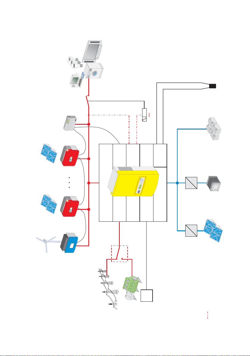
The following figure provides an overview of possible system configurations:
Loads
Batteriy
temperature sensor
Battery
Fuel Cell
*)
Can
N
TBAT
DC/DC
converter
R
E
W
O
P
M
E
SYST
T
R
O
P
E
R
Y
R
O
M
E
M
M
O
C
A
M
S
M
CO
T
E
N
M
O
C
B
S
U
x
o
B
y
n
b
n
e
Sunny
u
W
S
WebBox
PV x
Sunny Boy
t
l
s
n
u
s
o
i
u
a
t
l
g
F
b
h
a
e
n
r
r
e
c
u
i
u
th
e
s
r
r
l
t
r
i
p
d
e
a
r
E
E
B
O
Stö
Fa
*)
Com
Load_S
=
d
n
y
a
l
n
s
n
I
u
S
=
AC Output
G_Req
DC Input
Charge-
PV
controller
=
=
PV 1
Sunny Boy
Windy Boy
t
l
s
n
u
s
o
i
u
a
t
l
g
F
b
h
a
e
n
r
r
e
c
u
i
u
th
e
s
r
r
l
t
r
i
p
d
e
a
r
E
E
O
B
Fa
Stö
AC input
G_Ready
t
l
s
n
u
s
o
i
u
a
t
l
g
F
b
h
a
e
n
r
r
e
c
u
i
u
th
e
s
r
r
l
t
r
i
p
d
e
r
a
B
E
E
O
Stö
Fa
r
e
t
h
c
i
r
l
r
e
te
s
r
h
c
ve
e
n
i
w
g
g
n
n
i
i
r
r
t
t
s
S
k
c
i
i
a
a
t
t
l
l
tovo
tovo
o
o
h
h
P
SWR 3000
Windy Boy
P
Start
Utility
Auto
Control voltage
*) Not included in delivery
Generator
Description:
Page 12 SI3324/4248-14:SE2406 Installation Guide
Page 13
SMA Technologie AG The Sunny Island 3324/4248
PE N L
PE N L
SHIELD
G_RUN-
SHIELD
G_RUN+
S_IN-
S_OUT-
S_IN+
S_OUT+
FAN+
TBAT2
FAN-
TBAT1
LOAD_S
G_REQ
LOAD_S
G_REQ
CTS
RXD
S_GND
TXD
Shield
CAN_H
C_GND
CAN_L
Equipment
Ground
DC-
Negative
DC-
Positive
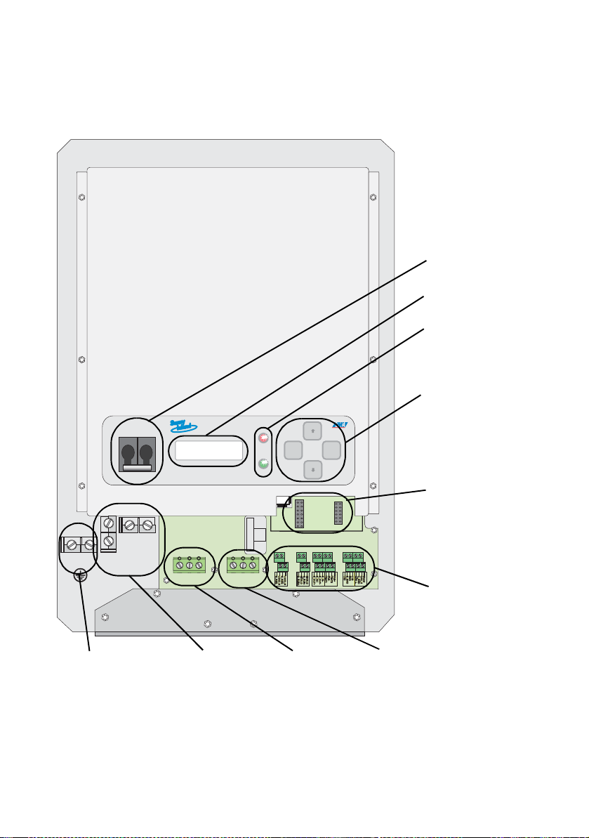
2.2 At a Glance
The following figure provides an overview of all control elements and connections of
the Sunny Island 3324/4248 (shown with cover removed).
Equipment
Ground
M
M
M
M
DC circuit
breaker
Display
LEDs showing
inverter
MMM
M
OFF
OFF
M
M
150V
200V
S5
S7
S9
S11
S13
S15
ENS2
ENS1
ENTERESC
MMM
M
operation: red
Keys
M
M
Socket for
Piggy-Back
(communication)
M
M
M
M
FAN+
CTS
Shield
RXD
CAN_H
S_GND
C_GND
TXD
CAN_L
Additional
connections (e.g.
communication,
M
M
control relays,...)
DC-
Negative
M
M
DC-
Positive
PENL
M
M
AC-OUTPUT AC-INPUT
M
M
M
M
M
M
PENL
M
M
SHIELD
S_IN-
LOAD_S
G_RUN-
S_OUT-
G_REQ
LOAD_S
G_REQ
M
M
TBAT2
SHIELD
S_IN+
FAN-
G_RUN+
S_OUT+
TBAT1
M
M
DC and AC
grounding
DC connection
(battery)
AC output
(Load)
AC input
(generator/utility)
Installation Guide SI3324/4248-14:SE2406 Page 13
Page 14
The Sunny Island 3324/4248 SMA Technologie AG
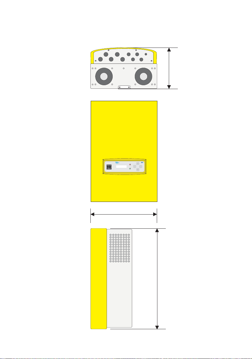
2.3 Dimensions
The Sunny Island 3324/4248 housing has the following dimensions:
245 mm
OFF
OFF
ENTERESC
430 mm
600 mm
Page 14 SI3324/4248-14:SE2406 Installation Guide
Page 15
SMA Technologie AG The Sunny Island 3324/4248
2.4 Scope of Delivery
The following elements are included:
• 1 Sunny Island 3324/4248 with housing cover (not fastened)
• 1 wall bracket
• 1 battery temperature sensor
• 5 cable feed-throughs M25
•5 nuts M25
• 1 double-hole insert for cable feed-throughs M25
• 4 cable feed-throughs M20
•4 nuts M20
• 4 double-hole inserts for cable feed-throughs M20 (2 x 6 mm)
• 1 cable feed-through M12
•1 nut M12
• 4 housing cover screws
• 1 screw for joining the angle bracket to the wall bracket
• 1 installation manual and 1 user manual
• 1 safety instructions (multilingual)
• 1 "Guarantee and Warranty Conditions" form
2.5 Required tools and resources
The following tools are recommended for mounting and installing the Sunny Island
3324/4248:
Installation of the Sunny Island 3324/4248 wall bracket:
1 drill
1 suitable drill (e.g. stone drill), Ø 8 mm
3 wall anchors for the wall bracket (e.g. SX 8)
3 hexagon bolts, 6x50 mm, washers
1 spirit level
refer to the "Installation" section for any further tools required
Installation of the Sunny Island 3324/4248:
1 stripping pliers
cable end sleeves
1 digital multimeter
Installation Guide SI3324/4248-14:SE2406 Page 15
Page 16
The Sunny Island 3324/4248 SMA Technologie AG
torque wrench with flathead screwdriver adapters:
1
size 10 mm
size 5.5 mm
size 2.5 mm
1 set hexagon/Allen keys, 3 mm to 8 mm
cable ties
1 cable knife
cable lugs
1 combination pliers
1 Phillips screwdriver, PH1
1 Phillips screwdriver, PH2
cables (see sections 5.1 "Grounding" (S. 33); 5.2 "DC Connection" (S.
36), 5.3 "AC Connection" (S. 40))
1 10 mm open-end/ring wrenches or socket wrench
1 19 mm open-end/ring wrenches
1 24 mm open-end/ring wrenches
1 30 mm open-end/ring wrenches
1
crimping tool for the cable end sleeves (suitable for cable cross-
sections of 2.5 mm², 4 mm², 10 mm² to 50 mm²)
1 flathead screwdriver, 0.4 x 2.5 mm
1 flathead screwdriver, 1.0 x 10 mm
1 flathead screwdriver, 1.0 x 5.5 mm
heat shrink tubing
1 diagonal cutting pliers
Installation of the Sunny Boy or Windy Boy:
1
1
service cable, to allow settings to be made (see section 2.7 "SMA
Products (Optional)" (S. 17))
PC/laptop with the Sunny Data software (available as a free
download from www.SMA.de)
access permission: In order to set grid relevant parameters in the
Sunny Boy (see section 13.2 "Setting Sunny Boy Parameters" (S.
1
118)), you need a special access code, the installer code. You can
obtain this personal code from the Sunny Boy hotline (telephone: +49
561 9522 499).
Page 16 SI3324/4248-14:SE2406 Installation Guide
Page 17

SMA Technologie AG The Sunny Island 3324/4248
2.6 Accessories (optional)
The following accessories are not essential for operating a Sunny Island 3324/4248,
however they extend the range of possible applications in a stand-alone grid:
• 1 GenMan (generator manager) (SMA order number: "SI-GenMan-TFH-230")
Allows the Sunny Island 3324/4248 to control generators requiring more than a
simple start/stop (2-wire) signal for remote control (see section 12.3 "GenMan"
(Page 113)).
• 1 separate load disconnecting switch for the batteries (SMA order number: "SIBattCase.01-200" for SI4248; "SI-BattCase.01-250" for SI3324)
Allows rapid, safe isolation of the Sunny Island 3324/4248 from the connected
batteries and also provides cable protection (see section 5.2 "DC Connection"
(Page 36)).
• 1 service cable for data transfer (SMA order number: "USBPBS-11"-USB-ServiceInterface). You also require the free "Sunny Data" software (see below).
Allows connection of a PC/laptop for communicating with the Sunny Island
3324/4248 in order to set parameters and for data read-outs (see section 15
"Communication Interface" (Page 123)).
SMA Technologie AG also offers an extensive range of products allowing you to
communicate with the Sunny Island 3324/4248, for data read-outs and much more.
Among these devices are:
• Sunny Boy Control
• Sunny Boy Control Plus
•WebBox
The "Sunny Data" and "Sunny Data Control" software, which you can use to make
settings in and read/analyze data from your inverter, can be downloaded for free
from the SMA Technologie AG website at www.SMA.de (see section 20 "Contact"
(Page 151)).
2.7 SMA Products (Optional)
A stand-alone system using the Sunny Island 3324/4248 as the grid controller can
also be fed with other alternative energy sources. SMA Technologie AG offers the
following inverter products (see figure Page 12):
• Sunny Boy inverters (for feeding in from PV systems): SB 700/SB 1100/
SB 1100LV/SB 1700/SB 2500/SB 2800i/SB 3000/SB 3300/SB 3800/
SMC 5000/SMC 6000/SMC 6000TL/SMC 7000TL/SMC 8000TL
Installation Guide SI3324/4248-14:SE2406 Page 17
Page 18

The Sunny Island 3324/4248 SMA Technologie AG
• Windy Boy inverters (for feeding in from wind turbines or hydropower systems):
WB 1100/WB 1700/WB 2500/WB 2800i/WB 3000/WB 3300/WB 3800/
WB 6000
• Hydro-Boy inverters (for feeding in from fuel cell systems)
2.8 Type Plate/Firmware Version
You can identify the Sunny Island 3324/4248 from the type plate and the firmware
version.
The type plate is located on the left side of the housing (when the Sunny Island 3324/
4248 hangs vertically on the wall bracket).
You can call up the firmware version of your Sunny Island 3324/4248 under the "312 FWVers" parameter (see section 17.2.3 "System and Fault Messages"
(Page 140)). Information on firmware updates is provided in section 16 "Updating
Firmware" (Page 127).
Page 18 SI3324/4248-14:SE2406 Installation Guide
Page 19
SMA Technologie AG Safety Instructions
3 Safety Instructions
3.1 Important Operational Notes
Please follow all operating and safety instructions in this manual. Failure to follow
these instructions could result in damage to the inverter and cause personal injury.
Carefully read the safety instructions before installing and commissioning the
inverter.
Ensure that the handbook are stored in an easily accessible location.
The Sunny Island 3324/4248 may only be installed or opened by
qualified personnel (electricians).
Never attempt to repair the inverter yourself. Unprofessional
repair work can be dangerous. Please consult your dealer or the
manufacturer if a fault occurs.
Be sure to observe all applicable regional standards and
guidelines.
The own consumption of the Sunny Island 3324/4248 discharges
the batteries, in standby mode (inverter DC disconnect is on,
inverter is in STOP mode and must be started manually) this load
is about 4 W and in idle mode (inverter is on, in invert mode, no
AC loads are present) it is about 22 W. You should take note of this
when you
• wish to install the Sunny Island 3324/4248 but do not wish to
immediately use it,
• or when operating the Sunny Island 3324/4248 for longer
times without recharge possibilities (e.g. in winter with snow on
your modules).
In these cases, you should set the Sunny Island 3324/4248 to Stop
mode (see section 9.3 "Switching Off" (S. 85)) and disconnect it
from the batteries via the DC circuit breaker.
Installation Guide SI3324/4248-14:SE2406 Page 19
Page 20

Safety Instructions SMA Technologie AG
3.2 Potential Hazards
Like any other power converter, the Sunny Island 3324/4248 is an electrical device
that presents certain hazards when operated.
Life-threatening voltages and currents exist within the Sunny
Island 3324/4248. Complete protection against accidental contact
is only provided when the following points are followed according
to the handbook:
• the inverter has been mounted correctly
• the inverter has been properly grounded
• all connections to the inverter
are made correctly
• the cover of the housing is securely closed
Failure to observance of these regulations may result in persons
suffering life-threatening injuries due to electric shock or parts of
the system being damaged.
Page 20 SI3324/4248-14:SE2406 Installation Guide
Page 21
SMA Technologie AG Safety Instructions
Before performing any maintenance work, installation work or an
EPROM change on the Sunny Island 3324/4248, you must make
absolutely sure that all inverters built in or connected to the system
are completely isolated from all voltage sources (batteries, (standalone-)grid, generator). Ensure that the system cannot be
accidentally switched on again. Proceed in the order given below:
• Switch off all loads.
• Press and hold the "ESC" key until the "To STOP press ENTER"
message appears.
• Press "ENTER".
• Switch off the Sunny Island 3324/4248 using the DC circuit
breaker and also disconnect the inverter from the batteries (e.g.
using the optional SI-BattCase load break switch).
• Then disconnect the Sunny Island 3324/4248 from the grid/
generator.
• Make sure that the Sunny Island 3324/4248 has been
disconnected from all voltage sources.
• Wait at least three minutes to let the capacitors discharge and
allow the voltage inside the inverter to drop to a safe level.
• Open the housing cover and ensure the inverter is not under
voltage.
Use only rechargeable lead acid batteries. The use of other types
of battery can lead to personal injury and material damage.
The Sunny Island 3324/4248 can start up automatically. When
working on the stand-alone grid, ensure that ALL sources of AC
and DC power in the system have been switched off (see above).
When touching the inverter, please note that some housing
components of the Sunny Island 3324/4248 heat up during
operation. Temperatures may exceed 60°C. This represents a risk
of burns.
Installation Guide SI3324/4248-14:SE2406 Page 21
Page 22
Safety Instructions SMA Technologie AG
This inverter has NOT been designed to supply life-sustaining
medical devices. The Sunny Island 3324/4248 may not be used in
installations where a power outage could result in personal injury.
This inverter is suitable only for installation in enclosed spaces.
Therefore, do not expose it to moisture, rain or direct sunshine (IP
category 30).
The Sunny Island 3324/4248 has been designed for use at
elevations up to 2000 m above sea level. Please contact SMA
Technologie AG before using the inverter at elevations above
2000 m.
Page 22 SI3324/4248-14:SE2406 Installation Guide
Page 23

SMA Technologie AG Installation
4 Installation
Please take note of the required installation conditions specified in section 4.1
"Preparation" (Page 23) before mounting, installing and commissioning the Sunny
Island 3324/4248.
4.1 Preparation
4.1.1 Lifting/Moving
The Sunny Island 3324/4248 weighs 39 kg. Ensure that at least
two people are available for installing the inverter. Always wear
personal protective equipment (protective clothing, gloves, safety
boots) to avoid the danger of injuries.
4.1.2 Unpacking
Before installing the Sunny Island 3324/4248 make sure that all parts are included
in the delivery.
• Carefully check the packaging and the Sunny Island 3324/4248 for any signs of
damage. Please note that the housing cover is delivered unmounted. Carefully
separately remove the cover and the inverter from the packaging and do not
install the cover until the inverter is properly mounted and installed, as described
in section 6 "Removing the Cover" (Page 55).
• Ensure that all parts are included in the delivery (see section 2.4 "Scope of
Delivery" (Page 15)).
• Enter the type and serial number of the inverter into the "Guarantee and
Warranty Conditions" form.
• Keep the documents in a location where they will be easy to find later.
If something is missing or the Sunny Island 3324/4248 has been damaged during
shipment, contact SMA Technologie AG immediately. Information is provided in
section 20 "Contact" (Page 151) of this installation manual.
Keep the packaging in case you need to return the battery inverter or its
accessories.
Installation Guide SI3324/4248-14:SE2406 Page 23
Page 24
Installation SMA Technologie AG
4.1.3 Installation Site
The Sunny Island 3324/4248 weighs 39 kg. Please take this
weight into account when choosing the installation site and
method of installation of the Sunny Island 3324/4248.
Protect the Sunny Island 3324/4248 from direct sunlight. High
temperatures lead to lower performance of the battery inverter.
The ambient temperature must not be outside the - 25°C to
+ 50°C range.
39 kg
Do not install the Sunny Island 3324/4248
• on flammable materials,
• in areas where there are easily flammable substances,
• in potentially explosive areas!
Never install the Sunny Island 3324/4248 in rooms where a
danger of explosion exists!
Page 24 SI3324/4248-14:SE2406 Installation Guide
Page 25
SMA Technologie AG Installation
4.1.4 Minimum Clearance
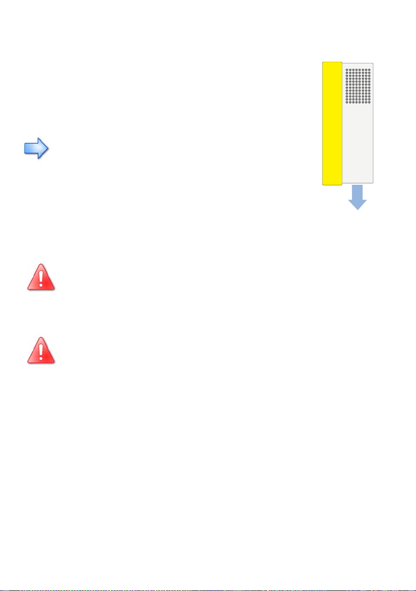
Air enters the Sunny Island 3324/4248 through the underside of the housing and
then flows through the inverter before exiting through the air grills on top of the
housing.
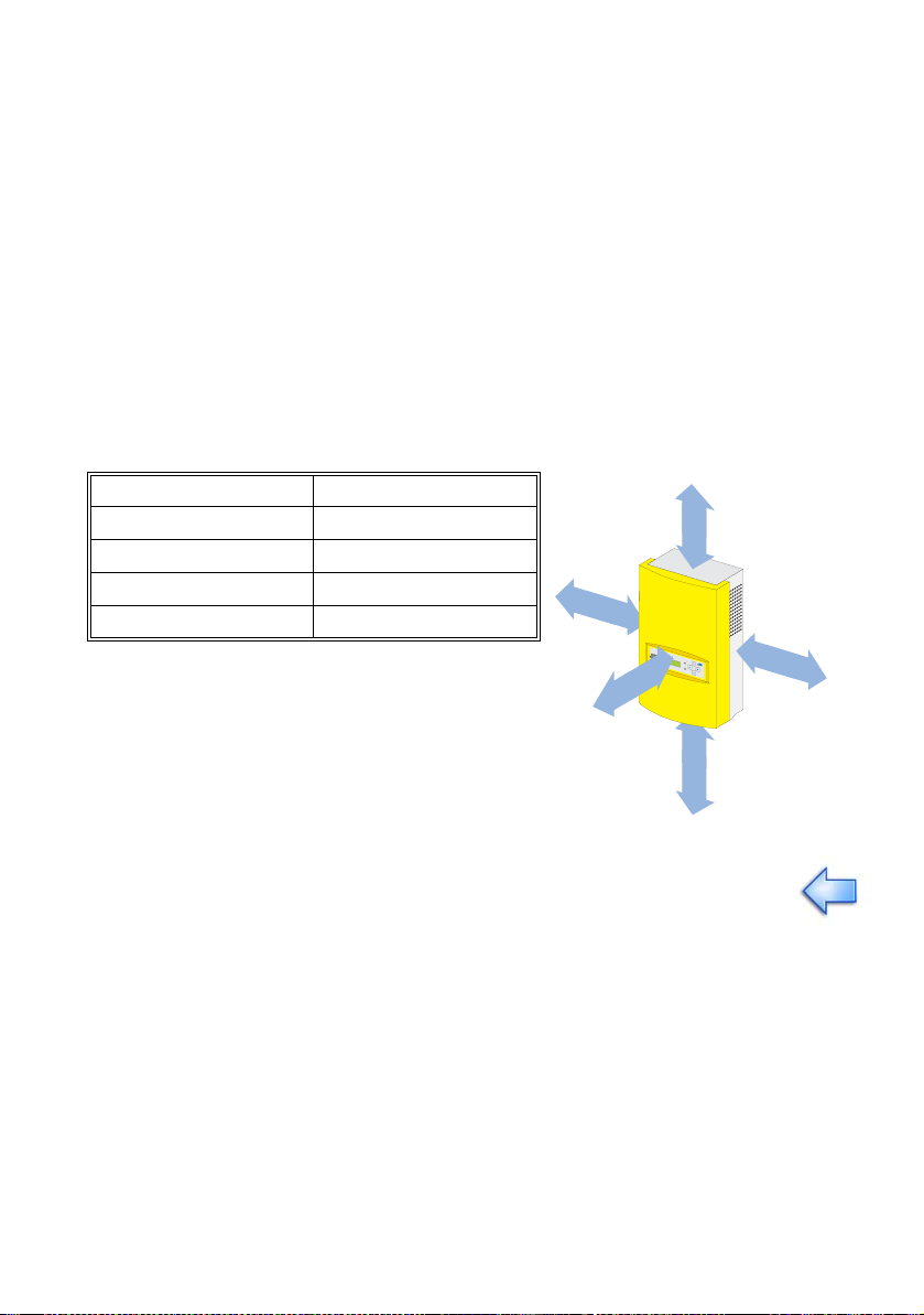
When installing the inverter, a minimum clearance of 20 cm at the sides and 10 cm
above the housing must be provided to ensure adequate ventilation of the Sunny
Island 3324/4248.
All external cables are connected through the underside of the housing. This requires
a minimum clearance of at least 30 cm.
Operation of the inverter and reading the display is much easier when the Sunny
Island 3324/4248 is installed with the display at eye-level with at least 50 cm
clearance in front. A minimum clearance of at least 10 cm is essential in order to
install the housing cover.
Minimum Clearance
Sides 20 cm
Top 10 cm
Underneath 30 cm
Front 10 cm
20
cm
10 c m
S
u
n
n
y
I
s
l
a
n
d
20 cm
10 cm
30 cm
When installing the Sunny Island 3324/4248 in smaller rooms, make sure that
adequate ventilation is available. The inverter produces heat when operating
that must be removed.
Installation Guide SI3324/4248-14:SE2406 Page 25
Page 26
Installation SMA Technologie AG
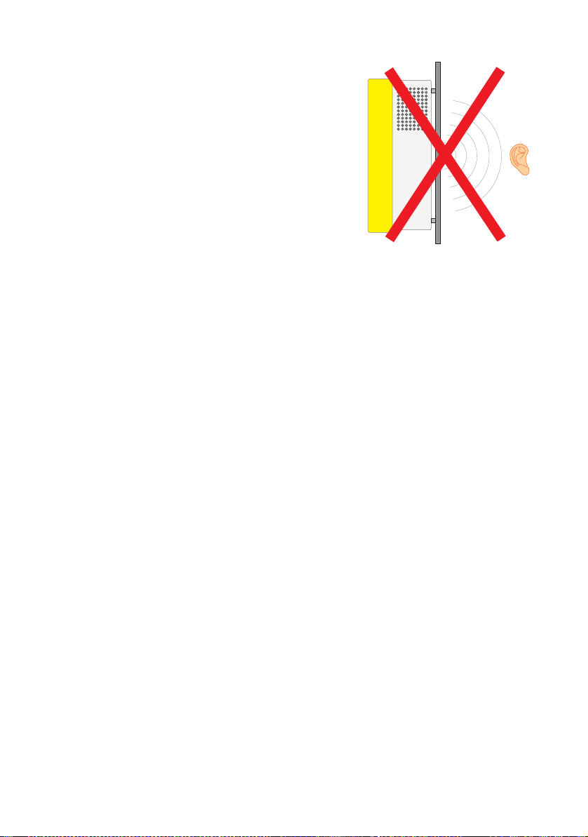
In domestic installations, the inverter should not be
mounted on plasterboard walls, wooden boarding
or similar as otherwise audible vibrations are likely
to result.
SMA Technologie AG recommends securing the
Sunny Island 3324/4248 to a solid surface.
Page 26 SI3324/4248-14:SE2406 Installation Guide
Page 27
SMA Technologie AG Installation
4.1.5 Wall Mounting
The Sunny Island 3324/4248 should be operated hanging vertically. To make the
job easier, we recommend you use the supplied wall bracket to mount the Sunny
Island 3324/4248 and use a spirit level to ensure correct alignment. The condition
and type of material used in the mounting surface determines the manner in which
the wall mounting is fastened.
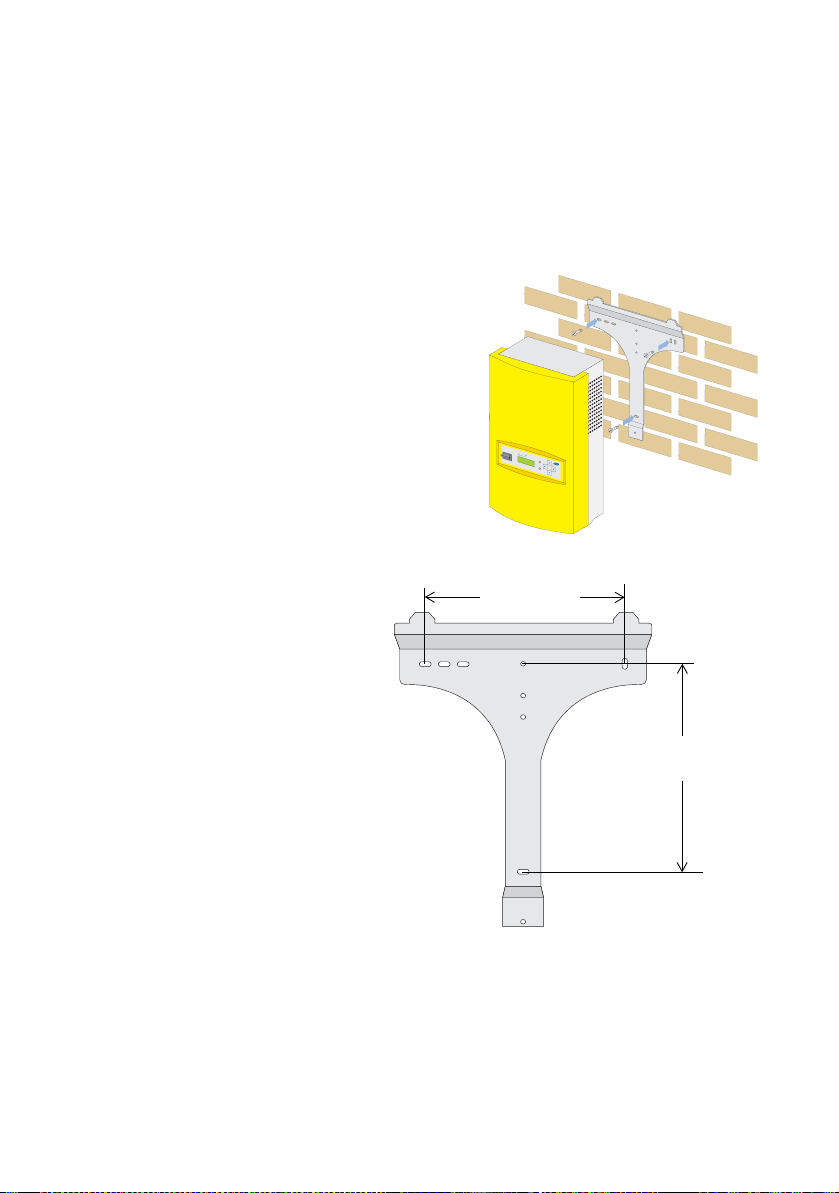
In solid concrete or block walls the wall
bracket is fastened using the three outer holes.
Use type SX 8 wall anchors and (e. g.)
stainless steel hexagon bolts (6 mm x 50 mm)
with suitable washers, according to the DIN
571 standard.
S
u
n
n
y
I
s
l
a
n
d
This figure shows a detailed view of
the center distances of the holes for
260 mm
the wall bracket when installing on
a solid concrete or block wall.
310 mm
Installation Guide SI3324/4248-14:SE2406 Page 27
Page 28
Installation SMA Technologie AG
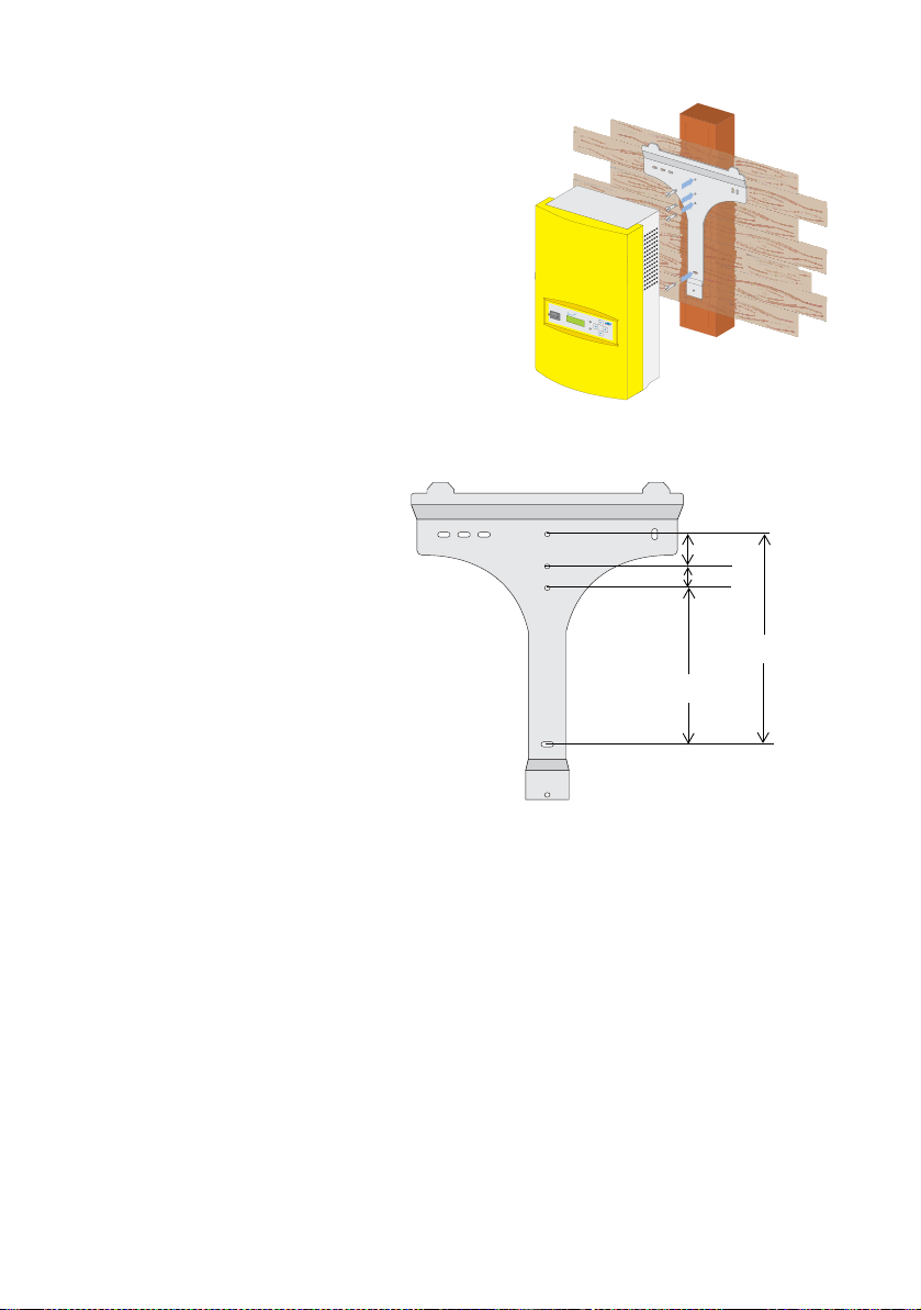
If the Sunny Island 3324/4248 is to be
installed on laths, then use the four middle
holes in the wall bracket. Ensure that the wall
bracket is positioned over a wall stud. Make
sure that the wall where you intend to install
the Sunny Island 3324/4248 is vertical and
can carry the weight of the Sunny Island
3324/4248 (39 kg) on a long-term basis.
Use (e.g.) stainless steel Phillips screws (6
mm x 50 mm) with suitable washers,
Sunny
Island
according to the DIN 571 standard.
This figure shows a detailed view
of the the center distances of the
holes for the wall bracket when
installing on a single wall stud.
45 mm
30 mm
310 mm
235 mm
Page 28 SI3324/4248-14:SE2406 Installation Guide
Page 29
SMA Technologie AG Installation
4.2 Mounting the Sunny Island 3324/4248
The following section describes the installation of the Sunny Island 3324/4248 in
detail. Keep to the order of operations suggested here:
1. Angle bracket on the bottom of the housing
2. Wall bracket
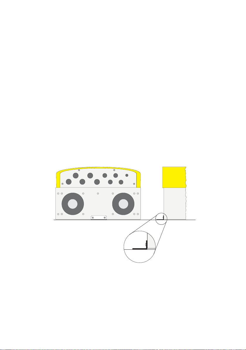
4.2.1 Angle bracket on the underside
The angle bracket on the underside of the Sunny Island 3324/4248 is mounted
backwards on delivery to avoid damage during transport. The angle bracket is used
to fasten the inverter to the wall bracket (see section 4.2.2 "Wall Bracket"
(Page 30)).
Before installing the inverter, you must first unscrew this angle bracket and then rotate
it so that the flange points downwards when the Sunny Island 3324/4248 hangs
vertically on the wall. The angle bracket can now be again screwed to the underside
of the Sunny Island 3324/4248, at the side of the the inverter that lies against the
wall (see figure below).
Underside view
Angle bracket
mounted with
flange pointing
downwards
Side view
Wall
Installation Guide SI3324/4248-14:SE2406 Page 29
Page 30
Installation SMA Technologie AG
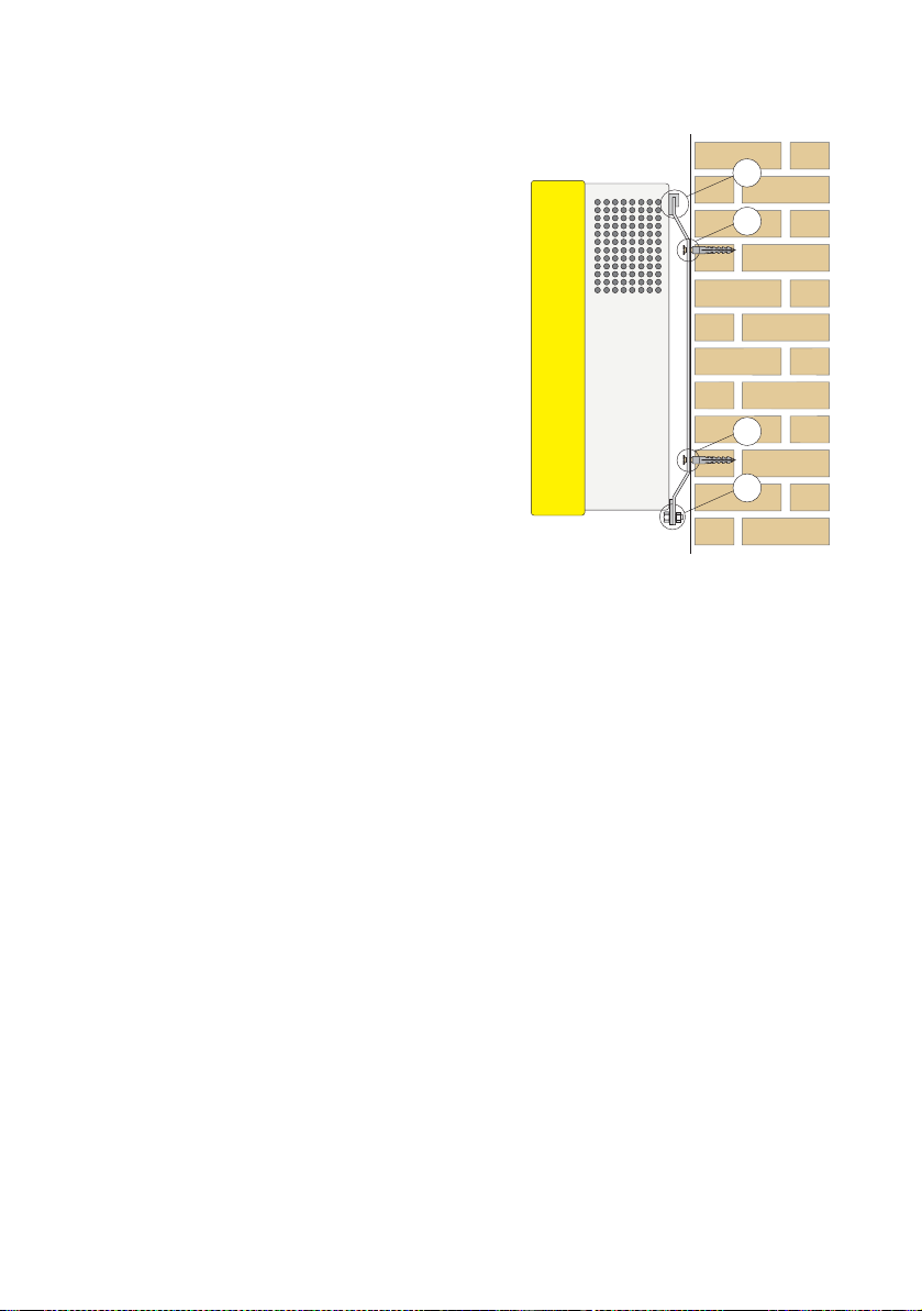
4.2.2 Wall Bracket
1. Mount the wall bracket (1). You can use
the wall bracket as a drilling template to
mark the positions for drilling the holes.
2
2. Then hook the Sunny Island 3324/4248
onto the wall bracket (2) at its upper
mounting plate so that it cannot be
moved sideways.
3. Secure the Sunny Island 3324/4248
against being raised by screwing the
angle bracket (see section4.2.1 "Angle
bracket on the underside" (Page 29)) to
the lower threaded holes of the wall
bracket using the supplied M6 x 10 mm
bolt.
4. Make sure the Sunny Island 3324/4248
is positioned securely on the bracket.
1
1
3
Page 30 SI3324/4248-14:SE2406 Installation Guide
Page 31

SMA Technologie AG Electrical Connection
5 Electrical Connection
This section describes the electrical connection of the Sunny Island 3324/4248 to the
existing components of your stand-alone grid.
The electrical installation of the Sunny Island 3324/4248 must be made by
trained specialists only. Before beginning to install your Sunny Island 3324/
4248, identify any potential hazards and take any necessary precautions (see
section 3 "Safety Instructions" (Page 19)).
Incorrect connection may result in operational disturbances or
cause damage to the inverter or system.
All connection cables are fed through the feed-throughs on the underside of the
inverter (see following figure) and connected to the appropriate connection terminals
inside the Sunny Island 3324/4248.
DC negative
Grounding
DC positive
AC
output
AC
input
Additional
connections (e.g.
communication)
Battery
temperature
Use the metric-thread cable screw connections provided to fasten the cables inside
the Sunny Island 3324/4248 housing in a manner conforming to the appropriate
standards. The metric-thread cable screw connections guarantee a dust-free and
waterproof installation of the cables in the housing and also provide strain relief for
Installation Guide SI3324/4248-14:SE2406 Page 31
Page 32

Electrical Connection SMA Technologie AG
the cable connection terminals. Close all unused openings in the housing using the
appropriate dummy plugs (included in delivery) to properly protect the Sunny Island
3324/4248 from dust and water.
You can obtain an overview of the different components and connection areas of the
Sunny Island 3324/4248 by referring to the figure on Page 13.
Detailed installation descriptions of the connections are provided in the following
sections:
• Grounding (section 5.1 "Grounding" (Page 33))
• DC connection (section 5.2 "DC Connection" (Page 36))
• AC connection (section 5.3 "AC Connection" (Page 40))
• inverter fan (section 5.4.1 "Cooling Fans" (Page 45))
• Battery temperature sensor (section 5.4.2 "Battery Temperature Sensor"
(Page 46))
• Load shedding (section 5.4.3 "Load shedding" (Page 48))
• Generator start (section 5.4.4 "Generator Start with a Single Contact" (Page 50))
• Generator start return signal (section 5.4.5 "Generator Start Using GenMan"
(Page 52))
• Communication (section 5.5 "Connection of the Communication Interface"
(Page 54))
Page 32 SI3324/4248-14:SE2406 Installation Guide
Page 33

SMA Technologie AG Electrical Connection
5.1 Grounding
In stand-alone configurations, the (protective) ground of the Sunny Island
3324/4248 and its individual components must be wired differently
depending on the design of the grid structure. All valid standards and
guidelines must be taken into account!
Only put the Sunny Island 3324/4248 into operation when it has
been properly externally grounded according to the relevant
regulations.
To allow different types of grounding, the N connection of the
Sunny Island 3324/4248 is NOT connected to PE at the factory.
However, since a connection between N and PE is required for
correct operation, this must be done outside of the inverter.
Due to filter measures in the inverter, increased leakage currents
against PE can occur during operation. For this reason, a "fixed
connection" of ground must be implemented according to EN
50178. Ground the inverter with a copper conductor (at least 10
mm² cross-section), or with two separate copper conductors with a
cross-section of at least 4 mm² each.
External grounding of the negative pole of the batteries is possible, because
the batteries and the grid side are galvanically isolated within the Sunny Island
3324/4248. In this case, make sure that the high currents that may occur under
fault conditions can be adequately diverted.
The grounding conductors (DC and AC) must be connected to the connection
terminals labeled as "Grounding" (see figure in section2.2 "At a Glance" (Page 13)).
Installation Guide SI3324/4248-14:SE2406 Page 33
Page 34

Electrical Connection SMA Technologie AG
Installation of the grounding conductors occurs in five steps:
Step 4.
Steps
1. + 3., 5.
1. Install an M25 metric-thread cable screw connection (included in delivery) in the
"Grounding" cable feed-through (see figure Page 31).
- Remove the dummy plug covering the cable feed-through.
- Insert the metric-thread cable screw connection into the opening in the
housing.
- Screw the counter-nut onto the cable screw connection thread inside the
housing.
2. Remove the protective insulation from the conductor and fit a suitable cable end
sleeve to the exposed end of the conductor.
3. Feed the grounding conductor through the metric-thread cable screw connection
into the housing of the Sunny Island 3324/4248.
4. Insert the conductor with the cable end sleeve into the ground connection
terminal and tighten the screw firmly (torque 4.0 Nm to 5.7 Nm).
5. Then tighten the metric-thread cable screw connection.
Page 34 SI3324/4248-14:SE2406 Installation Guide
Page 35

SMA Technologie AG Electrical Connection
Calculating the Required Grounding Conductor Cross-section
SMA Technologie AG cannot calculate generally valid values for the required cross-
section of the grounding conductor for external grounding of the negative pole of the
batteries. The conductor dimensions depend on the type of batteries connected, the
external fuse (DC side) and the material used in the the grounding conductor.
However, the cross-section can be easily calculated using a formula.
Exact calculation of the grounding conductor cross-section must take account
of the regionally applicable standards and guidelines (e.g DIN VDE 0100 Part
540).
The required cross-section of a (copper) grounding conductor can be calculated
using the following formula. Trigger times, e.g. for the integrated DC circuit breaker,
of about 25 ms are typical for short circuit currents between 2000 A and 10,000 A.
t = Trigger time in seconds (s)
= Maximum battery current (short circuit current) in
I
SC
amperes (A)
S = Conductor cross-section in square millimeters (mm²)
A grounding conductor of 16 mm² cross-section is thus adequate for short circuit
currents up to 10,000 A.
Installation Guide SI3324/4248-14:SE2406 Page 35
Page 36

Electrical Connection SMA Technologie AG
5.2 DC Connection
5.2.1 Safety Precautions/Conditions
Connect a suitable battery to the DC side. DC must be connected observing all valid
regulations (e.g. DIN VDE 0510, Rules for Accumulators and Battery Systems).
All safety and maintenance instructions provided by the battery
manufacturer must be heeded.
Working in the vicinity of lead acid batteries is dangerous!
Batteries produce explosive gases in normal operation. Ensure
that the battery compartment is sufficiently ventilated. If battery
boxes are used, the accumulation and concentration of hydrogen
gas in "bubbles" in the upper portion of the housing must be
prevented. Aerate the battery compartment from the highest
point. Open flames or smoking in the vicinity of the battery are
NOT permitted under ANY CIRCUMSTANCES!
Danger of acid injury:
Battery acid is extremely corrosive. Always wear protective
gloves and eye protection. Batteries must not be tilted, since acid
may leak out of the ventilation holes.
Use appropriate (insulated) tools for installation and wiring of the
batteries (danger of short circuits and arcing).
When connecting the battery, ensure that the cable has sufficient
cross-section and that the connections have the correct polarity.
The battery cables should be as short as possible. Long cables and an
insufficient cable diameter reduce system efficiency and overload capability,
thus negatively affecting the battery management function.
Do not lay the battery feed cables under plaster or in armored plastic pipes.
Large currents flow through the battery cables so that they can become very
warm.
Page 36 SI3324/4248-14:SE2406 Installation Guide
Page 37

SMA Technologie AG Electrical Connection
If you do not wish to use the system for an extended period of time, then
always disconnect the battery cables from the inverter.
The Sunny Island 3324/4248 does not connect either the positive or the
negative DC pole to ground. If a connection is required, then this must be
made by an installer.
5.2.2 Cable Protection
In addition to the DC circuit breakers within the Sunny Island 3324/4248, install a
separate load disconnecting switch as close as possible to your batteries. Install a
suitable fuse plug for the load disconnecting switch according to the maximum
specified DC current (e.g NH1 at 200 A for the SI4248 and NH1 at 250 A for the
SI3324).
If no cable protection (load disconnecting switch) exists, then the
DC cables must be protected against ground faults and short
circuits. The internal DC fuse of the Sunny Island 3324/4248 is
designed such that it can interrupt currents of up to 10 kA.
For short circuit currents greater than 10,000 A an additional
thermal fuse is absolutely essential ("SI-BattCase.01-200" for the
SI4248 or "SI-BattCase.01-250" for the SI3324).
Installation Guide SI3324/4248-14:SE2406 Page 37
Page 38

Electrical Connection SMA Technologie AG
5.2.3 Connection
Only connect the external load disconnecting switch/battery
cables to the battery when all other installation work is finished.
The Sunny Island 3324/4248 has two "DC negative" and two "DC positive"
connection terminals (max. 35 mm²) for the battery cables.
Install the DC connections in the following sequence:
Steps
4. + 5.
Steps
1. + 3., 6.
1. Install an M25 metric-thread cable screw connection (included in delivery) in
each of the the "DC negative" and "DC positive" cable feed-throughs (see figure
Page 31).
- Remove the dummy plugs covering the cable feed-throughs.
- Insert the cable screw connection thread into the opening in the housing.
- Screw the counter-nut onto the cable screw connection thread inside the
housing.
Page 38 SI3324/4248-14:SE2406 Installation Guide
Page 39

SMA Technologie AG Electrical Connection
2. Remove the protective insulation from each of the conductors and fit a suitable
cable end sleeve to the exposed ends of each conductor.
3. Install the "DC negative" and "DC positive" cables, one after the other. First feed
the negative conductor through the metric-thread cable screw connection into
the housing of the Sunny Island 3324/4248.
4. Insert the conductor with the cable end sleeve into one of the "DC negative"
connection terminals and tighten the retaining screw firmly (torque 4.0 Nm to
5.7 Nm).
5. Then insert the positive conductor through the metric-thread cable screw
connection into the "DC positive" terminal of the Sunny Island 3324/4248 and
tighten the retaining screw firmly (torque 4.0 Nm to 5.7 Nm).
6. Then tighten both of the metric-thread cable screw connections firmly.
No other devices should be connected to the cables connecting the batteries
with the Sunny Island 3324/4248 DC connection. Connection of other DC
devices to the batteries should be done using separate cables leading directly
to the batteries.
Installation Guide SI3324/4248-14:SE2406 Page 39
Page 40

Electrical Connection SMA Technologie AG
5.3 AC Connection
5.3.1 Cable Protection
A sub-distribution panel must be used to connect the Sunny Island 3324/4248 to the
AC loads, a generator or the existing public grid. The sub-distribution panel must be
equipped with appropriate circuit breakers. Be sure to observe all the applicable
regional standards and guidelines.
The maximum permissible current that may flow through the AC input of the
Sunny Island 3324/4248 is 56 A.
Typical color codings for the AC installation are:
• Phase conductor (L conductor): brown
• Neutral conductor (N): blue
• Protective ground conductor (PE): green/yellow stripes
The Sunny Island 3324/4248 may only be used in grids where the N conductor is
grounded.
The neutral conductor (N conductor) is looped through the Sunny Island 3324/
4248, i.e. the N connection terminals of AC output and AC input are connected
inside the inverter.
Page 40 SI3324/4248-14:SE2406 Installation Guide
Page 41

SMA Technologie AG Electrical Connection
5.3.2 AC Output
The stand-alone grid sub-distribution (e.g. loads, PV generator (Sunny Boy), wind
turbine (Windy-Boy)) is connected to the AC output of the Sunny Island 3324/4248.
If you wish to provide separate protection for an individual load circuit, then use a
maximum 16 A, B-type circuit breaker. In the case of a short circuit, the Sunny Island
3324/4248 can still trigger these types of automatic breakers:
Step 4.
Steps
1. + 3., 5.
1. Install an M25 metric-thread cable screw connection (included in delivery) in the
"AC output" cable feed-through (see figure Page 31).
- Remove the dummy plug covering the cable feed-through.
- Insert the metric-thread cable screw connection into the opening in the
housing.
- Screw the counter-nut onto the cable screw connection thread inside the
housing.
2. Remove the protective insulation from each of the three conductors and fit a
suitable cable end sleeve to the exposed ends of each conductor.
3. Feed the three-conductor cable through the metric-thread cable screw
connection into the housing of the Sunny Island 3324/4248.
Installation Guide SI3324/4248-14:SE2406 Page 41
Page 42

Electrical Connection SMA Technologie AG
4. Install the three PE, N and L AC output conductors, one after the other. Insert
the appropriate conductor into the appropriate PE, N or L "AC output"
connection terminal and tighten the terminal screw firmly (torque 2.0 Nm to 4.0
Nm).
5. Once all three connections have been made, tighten the metric-thread cable
screw connections firmly.
5.3.3 AC Input
The output of the generator/public grid is connected to the AC input of the Sunny
Island 3324/4248. Wire the AC input in the following sequence:
Step 4.
Steps
1. + 3., 5.
1. Install an M25 metric-thread cable screw connection (included in delivery) in the
"AC input" cable feed-through (see figure Page 31).
- Remove the dummy plug covering the cable feed-through.
- Insert the metric-thread cable screw connection into the opening in the
housing.
- Screw the counter-nut onto the cable screw connection thread inside the
housing.
Page 42 SI3324/4248-14:SE2406 Installation Guide
Page 43

SMA Technologie AG Electrical Connection
2. Remove the protective insulation from each of the three conductors and fit a
suitable cable end sleeve to the exposed ends of each conductor.
3. Feed the three-conductor cable through the metric-thread cable screw
connection into the housing of the Sunny Island 3324/4248.
4. Install the three PE, N and L AC input conductors, one after the other. Insert the
appropriate conductor into the appropriate PE, N or L "AC input" connection
terminal and tighten the terminal screw firmly (torque 2.0 Nm to 4.0 Nm).
5. Once all three connections have been made, tighten the counter-nut of the
metric-thread cable screw connection firmly.
Installation Guide SI3324/4248-14:SE2406 Page 43
Page 44

Electrical Connection SMA Technologie AG
5.4 Additional Connections
For installing the connections described below (battery temperature sensor, control
relays, communication, ...) either one cable with an external diameter between 7 mm
and 14 mm, or two cables with an external diameter of 6 mm each, may be used for
each cable feed-through in the underside of the housing.
The following figure provides an overview of the additional connection terminals. The
two terminal strips for the connections are arranged offset above each other.
G_RUN-
G_RUN+
S_OUT-
S_OUT+
G_REQ
G_REQ
CAN_H
CAN_L
TBAT2
TBAT1
2
5
SHIELD
SHIELD
LOAD_S
LOAD_S
S_IN+
S_IN-
FAN+
FAN-
C_GND
Shield
7
3
Control
relay: load
shedding
Control
relay:
generator
Battery
temperature
sensor
Signal
generator start
cooling fans
Communication:
RS232 or
RS485
Page 44 SI3324/4248-14:SE2406 Installation Guide
Page 45

SMA Technologie AG Electrical Connection
5.4.1 Cooling Fans
The Sunny Island 3324/4248 has fans allowing the inverter to constantly feed heavy
loads even at high ambient temperatures. The fans are located in the rear of the
housing (not illustrated) and are already connected on delivery.
G_RUN-
G_RUN+
S_OUT-
S_OUT+
G_REQ
G_REQ
CAN_H
CAN_L
TBAT2
TBAT1
2
5
SHIELD
SHIELD
LOAD_S
LOAD_S
S_IN+
S_IN-
FAN+
FAN-
C_GND
Shield
7
3
Installation Guide SI3324/4248-14:SE2406 Page 45
Page 46

Electrical Connection SMA Technologie AG
5.4.2 Battery Temperature Sensor
The battery temperature sensor measures the temperature of the connected battery.
This is necessary since the optimum charging voltage for a lead acid battery is heavily
temperature-dependent. Further information is provided in section 11.1 "Charge
Control" (Page 102).
The Sunny Island 3324/4248 can only be put into operation once the battery
temperature sensor is connected.
Only use the battery temperature sensor provided with the
delivery.
Do NOT extend the battery temperature sensor cable!
Do not drill any holes in any part of the battery to mount the
sensor.
Proceed as follows to connect the battery temperature sensor to the Sunny Island
3324/4248:
Steps:
4. + 5.
G_RUN-
G_RUN+
S_OUT-
S_OUT+
G_REQ
G_REQ
CAN_H
CAN_L
TBAT2
TBAT1
2
5
SHIELD
SHIELD
LOAD_S
LOAD_S
S_IN+
S_IN-
FAN+
FAN-
C_GND
Shield
7
3
Steps:
1., 3., 6.
Page 46 SI3324/4248-14:SE2406 Installation Guide
Page 47

SMA Technologie AG Electrical Connection
1. Install an M12 metric-thread cable screw connection (included in delivery) in the
"Battery temperature sensor" cable feed-through (see figure Page 31).
- Remove the dummy plug covering the cable feed-through in the housing.
- Insert the metric-thread cable screw connection into the opening in the
housing.
- Screw the counter-nut onto the cable screw connection thread inside the
housing.
2. Feed the cable with the cable end sleeves through the metric-thread cable screw
connection into the housing of the Sunny Island 3324/4248.
3. Insert the conductor with the cable end sleeve into the "TBat1" connection
terminal and tighten the terminal screw firmly. The connection terminal
numbering is irrelevant, the polarity does not matter.
4. Then connect the second conductor to the "TBat2" connection terminal.
5. Now tighten the metric-thread cable screw connection firmly.
Installation of the Battery Temperature Sensor at the Battery.
Fasten the battery temperature sensor to the outside of one of the battery cells.
Choose a cell in the middle of the battery bank, the batteries generate the most heat
in this region during operation.
Installation Guide SI3324/4248-14:SE2406 Page 47
Page 48

Electrical Connection SMA Technologie AG
*)
N
Loads
AC-Output AC-Input
k1
K1
Sunny Island
N L
Load_S
Sunny Boy
5.4.3 Load shedding
The Sunny Island 3324/4248 can automatically switch off loads to protect the
batteries from deep discharge. To do this, an external power contactor, e.g. with a
230 V 16 A NO contact, must be installed between the Sunny Island 3324/4248
and the loads.
Installation of the load shedding system is strongly recommended in systems
with extensive AC-side coupling of solar power or wind power. This is the only
way to achieve safe operation of the system, even in cases of low energy
generation or very high consumption.
The external contactor is controlled by an internal relay (connection terminal
"Load_S"), which can be controlled using the "40-6 Load_Shedding" parameter. This
parameter is set to "OFF" at the factory. Please read section 8.6 "Automatic Load
Shedding Setting" (Page 80) for more information on this topic.
This wiring is shown in the following figure:
Page 48 SI3324/4248-14:SE2406 Installation Guide
Page 49

SMA Technologie AG Electrical Connection
Install the connections to the Sunny Island 3324/4248 as follows:
G_RUN-
G_RUN+
S_OUT-
S_OUT+
G_REQ
G_REQ
CAN_H
CAN_L
TBAT2
TBAT1
2
5
SHIELD
SHIELD
LOAD_S
LOAD_S
S_IN+
S_IN-
FAN+
FAN-
C_GND
Shield
7
3
1. Install an M20 metric-thread cable screw connection (included in delivery) in
one of the "Additional connections" cable feed-throughs (see figure Page 31).
- Remove the dummy plug covering the chosen cable feed-through in the
housing.
- Insert the cable screw connection thread into the opening in the housing.
- Screw the appropriate M20 counter-nut onto the cable screw connection
thread inside the housing.
2. Remove the protective insulation from the conductors and fit a suitable cable
end sleeve to the exposed ends of each conductor.
3. Feed the conductors through the metric-thread cable screw connection into the
housing of the Sunny Island 3324/4248.
4. Insert the first conductor with the cable end sleeve into one of the "Load_S"
connection terminal and tighten the terminal screw firmly. Then connect the
second conductor to the second "Load_S" connection terminal. The polarity of
the two conductors does not matter.
5. Now tighten the metric-thread cable screw connection firmly.
Installation Guide SI3324/4248-14:SE2406 Page 49
Page 50

Electrical Connection SMA Technologie AG
5.4.4 Generator Start with a Single Contact
The Sunny Island 3324/4248 can automatically start generators that can be started/
stopped using a single contact. This is done by the generator control relay
(GenRequest-Relay) integrated into the Sunny Island 3324/4248. The autostart
(single contact start) generator is directly connected to the "G_Req“ connection
terminals of the Sunny Island 3324/4248. Further information on parameter settings
and other methods of starting generators can be found in sections 8.5 "Operation
with a Generator" (Page 74) and 10.2 "PV Stand-alone System with Generator"
(Page 90).
G_RUN-
G_RUN+
S_OUT-
S_OUT+
G_REQ
G_REQ
CAN_H
CAN_L
TBAT2
TBAT1
2
5
SHIELD
SHIELD
LOAD_S
LOAD_S
S_IN+
S_IN-
FAN+
FAN-
C_GND
Shield
7
3
1. Install an M20 metric-thread cable screw connection (included in delivery) in
one of the "Additional connections" cable feed-throughs (see figure Page 31).
- Remove the dummy plug covering the chosen cable feed-through in the
housing.
- Insert the cable screw connection thread into the opening in the housing.
- Screw the appropriate M20 counter-nut onto the cable screw connection
thread inside the housing.
2. Remove the protective insulation from the conductors and fit a suitable cable
end sleeve to the exposed ends of each conductor.
Page 50 SI3324/4248-14:SE2406 Installation Guide
Page 51

SMA Technologie AG Electrical Connection
3. Feed the conductors through the metric-thread cable screw connection into the
housing of the Sunny Island 3324/4248.
4. Insert the first conductor with the cable end sleeve into one of the "G_Req"
connection terminals and tighten the terminal screw firmly. Then connect the
second conductor to the second "G_Req" connection terminal. The polarity of
the two conductors does not matter.
5. Now tighten the metric-thread cable screw connection firmly.
Installation Guide SI3324/4248-14:SE2406 Page 51
Page 52

Electrical Connection SMA Technologie AG
5.4.5 Generator Start Using GenMan
The Sunny Island 3324/4248 can also automatically start generators having more
than a 2-wire start contact by using the optionally available generator manager
(GenMan). As soon as the generator has started, the GenMan confirms proper
operation by sending a signal to the G_Run connections of the Sunny Island 3324/
4248.
G_RUN-
G_RUN+
S_OUT-
S_OUT+
G_REQ
G_REQ
CAN_H
CAN_L
TBAT2
TBAT1
2
5
SHIELD
SHIELD
LOAD_S
LOAD_S
S_IN+
S_IN-
FAN+
FAN-
C_GND
Shield
7
3
.
Connection Function
SHIELD shield
G_RUN– connected to Gen Ready– of the GenMan
SCHIRM shield
G_RUN + connected to Gen Ready + of the GenMan
Pay attention to the correct connection polarity when installing.
• Connect the GenMan minus output Gen Ready– to the G-RUN– terminal of the
Sunny Island 3324/4248.
• Wire the GenMan positive output Gen Ready+ to the G-RUN+ terminal of the
Sunny Island 3324/4248.
Page 52 SI3324/4248-14:SE2406 Installation Guide
Page 53

SMA Technologie AG Electrical Connection
5.4.6 Synchronization
These connections are intended as synchronization connections for possible future
communication systems and are not presently used.
Do not connect anything to these terminals.
Connection Function
S_IN - synchronization INPUT, negative
S_OUT - synchronization OUTPUT, negative
S_IN + synchronization INPUT, positive
S_OUT + synchronization OUTPUT, positive
Installation Guide SI3324/4248-14:SE2406 Page 53
Page 54

Electrical Connection SMA Technologie AG
5.5 Connection of the Communication Interface
The following communication interfaces can be built into the Sunny Island 3324/
4248:
•RS232
•RS485
The wiring of the Sunny Island 3324/4248 communication interfaces is described in
section 15.1 "Connection of the Interface" (Page 124).
A detailed wiring diagram for the communication interfaces for the entire
communications structure of your system can be found in the handbook for the
communications device you have chosen.
Page 54 SI3324/4248-14:SE2406 Installation Guide
Page 55

SMA Technologie AG Removing the Cover
6 Removing the Cover
The Sunny Island 3324/4248 enclosure has a removable cover. Remove this cover
only when installing the inverter or for required maintenance or repair work.
6.1 Removing the Cover
The Sunny Island 3324/4248 may only be installed or opened by
suitably qualified personnel (electricians).
Switch off the Sunny Island 3324/4248 and disconnect all voltage
sources (batteries, generator and any other energy sources).
Ensure that the system cannot be accidentally switched on again.
Proceed as follows:
1. Stop the Sunny Island 3324/4248 (see section 9.1 "Stopping" (Page 83)).
2. Switch off the inverter, as described in section 9.3 "Switching Off" (Page 85).
3. Remove the four Phillips screws on the underside of the Sunny Island 3324/
4248, as shown in the illustration below.
Installation Guide SI3324/4248-14:SE2406 Page 55
Page 56

Removing the Cover SMA Technologie AG
4. Remove the four Phillips screws (1).
4
5. Carefully pull the lower end of the housing
cover until it comes free from the housing
(2).
6. When removing the cover be sure that the
3
lower side of the cover is kept away from
the DC switch, to be sure that you do not
accidentally switch on the inverter.
7. Now slide the housing cover upwards (3).
8. Remove the cover and store it in a safe
place while mounting, installing or repairing
the inverter.
2
1
6.2 Installing the Cover
Before installing the housing cover of the Sunny
Island 3324/4248, ensure that all cables are properly laid and that all tools have
been removed from within the housing (see section 5 "Electrical Connection"
(Page 31)).
1. Hold the cover at an angle and hang it on the
upper side of the housing (1).
1
2. Then gently slide the housing cover down (2)
and towards the rear of the housing (3).
3. Fasten the housing cover to the Sunny Island
2
3324/4248 with the four Phillips screws (4)
(see figure Page 55). Tighten the screws evenly
and firmly.
3
4
Page 56 SI3324/4248-14:SE2406 Installation Guide
Page 57

SMA Technologie AG Operation
7 Operation
Before the first commissioning of the Sunny Island 3324/4248, read this
"Operation" section and become familiar with the inverter.
7.1 Control Elements
Functions, operating modes, parameters, data and fault messages are all displayed
in the two-line display of the Sunny Island 3324/4248. Use the arrow keys (↑ ↓), the
ESC key, and the ENTER key for navigation. The individual control elements can be
seen in the figure below.
DC circuit breaker
OFF
OFF
ENTERESC
LEDs showing
inverter operation
Display
Control keys
The following table shows the key functions:
Key Function
ESC
cancel, NO response, leave current menu, stop the inverter
(hold)
↑ navigate up one menu level, increase data value
↓ navigate down one menu level, decrease data value
ENTER
select a function, select a value, confirm changes, YES
response
Installation Guide SI3324/4248-14:SE2406 Page 57
Page 58

Operation SMA Technologie AG
The DC circuit breaker switches the Sunny Island 3324/4248 on and off. Note that
all voltage sources (batteries, (stand-alone) grid, generator) must be disconnected
from the Sunny Island 3324/4248 before the inverter is free of voltage (see section
9.3 "Switching Off" (Page 85)).
7.2 Changing Parameters
Use the <ENTER> key to open a menu. Use the ↑ (upwards) or ↓ (downwards) keys
to navigate through the selected menu (see "Menu structure" figure Page 62) in order
to view or change parameter values. As soon as the desired parameter appears in
the display, you can read the current parameter value.
The display always shows the first two digits of a
parameter. The menu structure and the
parameter assignment are explained in section
7.5 "Menu Structure" (Page 61).
An "Enter" arrow is displayed next to parameters
that you are allowed to change .
Screen display of (e.g.)
the
"23-4 AmpdcBatMax"
parameter:
AmpdcBatMax ‹23
10 A ↵
Note that some parameters can only be changed
when the inverter is in standby mode (see section
9.3 "Switching Off" (Page 85)). You can find the
parameters for which this applies in the tables in section 17.2.2 "Adjustable System
Parameters" (Page 134) and section17.2.4 "Operation (Operation)" (Page 141).
If you press the <ENTER> key, the "Enter" arrow begins to blink and you can then
use the arrow keys (↑ or ↓) to change the current parameter value.
As soon as the desired value appears in the display, press the <ENTER> key to save
the new value, or press the <ESC> key to discard the changes and exit the menu.
If you wish to exit the current menu level (e.g. "23-3 AmpHoursBat" parameter) then
press the <ESC> key. In this example, the cursor then jumps back to the "23-Battery
Settings" menu level.
Page 58 SI3324/4248-14:SE2406 Installation Guide
Page 59

SMA Technologie AG Operation
7.3 Explanation of the Light-emitting Diodes (LEDs)
A red LED and a green LED are located on the front side of the Sunny Island 3324/
4248. The following table explains their meaning:
Green LED Red LED Operating mode
ON ON INIT (initialization phase)
— — Standby
ON — Operation
BLINKING —
Derating
(power reduction)
—ONFault
7.4 Display
Information about the Sunny Island 3324/4248 is shown on the two-line LCD display.
Two lines are always shown when navigating up and down the menus.
During normal operation, the Sunny Island 3324/4248 shows the relative output
power, the operating mode of the inverter, the generator status (e.g. "L" see section
12.4 "Display Message" (Page 114)), fault messages and the status of the load
shedding and generator control relay.
Output power/charging power
Operating mode
[¿¿¿¿¿¿¿¿¿¿¿¿ ]
Load status
Fault display
>Invert L oo E
Direction of energy
Generator status
Request Type
Installation Guide SI3324/4248-14:SE2406 Page 59
Load shedding
relay status
Generator control
relay status
Page 60

Operation SMA Technologie AG
Explanation of the energy flow direction display:
">" = DC to AC (discharging mode)
"<" = AC to DC (charging mode)
Explanation of the load status display:
"]" = Normal
">" = Overload
You can find further information on the changing generator status display in section
12.4 "Display Message" (Page 114).
Page 60 SI3324/4248-14:SE2406 Installation Guide
Page 61

SMA Technologie AG Operation
7.5 Menu Structure
The menu structure is divided into two levels:
•User Level
•Installer Level
The menus allowing system parameters to be changed can only be reached after
entering the installer password (see section 8.3 "Password Entry" (Page 69)). Menus
protected in this manner are shown with a grey background in the following figure
(Installer Level). Menus shown with a white background are on the User Level and
can be accessed without a password. These menu parameters are used to monitor
and control the Sunny Island 3324/4248 in normal daily operation.
The main menu structure is divided into four different groups, each of which having
two subsequent submenus.
1. Meters: The "10-Meters" main menu has the following submenus: Sunny Island
3324/4248 measurements ("11-Inverter Meters"), battery measurements ("12Battery Meters") and generator measurements ("13-Generator Meters").
Individual measurement values can be seen in the next two menu levels.
2. Settings: Under the main menu "20-Settings" are four different submenus
allowing various system parameters to be viewed and changed. This affects
password entry ("21-Password Settings") and all system parameters relating to
the Sunny Island 3324/4248 ("22-Inverter Settings"), the batteries ("23-Battery
Settings") and the generator ("24-Generator Settings").
3. Diagnose: Under the main menu "30-Diagnose" are two different submenus
allowing various diagnostic parameters to be viewed. These are system data
("31-System Information"), and fault messages ("32-Error Information").
4. Operation: The main menu "40-Operation" allows viewing and changing of
the operating parameters (e.g. "40-8 SunnyBoys").
Please consult section 7.2 "Changing Parameters" (Page 58) for information
describing how to set the individual parameters.
You will find a tabular list of all parameters in section 17.2 "Menus Requiring the
Installer Password" (Page 132).
Installation Guide SI3324/4248-14:SE2406 Page 61
Page 62

Operation SMA Technologie AG
The following diagram provides an overview of the menu structure:
Home Screen
10 METERS
System Meters
20 SETTINGS
System Settings
30 DIAGNOSE
System Diagnose
40 OPERATION
System Operation
User Level
11 Inverter Meters
12 Battery Meters
13 Generator Meters
21 Password Settings
22 Inverter Settings
23 Battery Settings
24 Generator Settings
31 System Information
32 Error Information
11-1 VacInverter
11-2 AmpacInverter
11-3 FacInverter
11-4 PacInverter
12-1 BatVoltage
12-2 BatCurrent
12-3 BatTemp
12-4 BatState
12-5 BatChargeMode
12-6 TabsorbLeft
12-7 BatChargeVolt
13-1 VacGenerator
13-2 AmpacGenerator
13-3 FacGenerator
13-4 PacGenerator
21-1 Level [00] *****
22-1 VacNominal
23-1 VdcBatNominal
23-2 BatType
23-3 AmpHoursBat
23-4 AmpdcBatMax
24-1 GenControl
24-2 AmpacGenMax
24-3 GenOperation
31-1 DeviceConfig
31-2 FWVERS
31-3 SerNum
31-4 RunTime
32-1 Last
32-2 Hist
40-1 BatChargeMode
40-2 Autostart
Installer Level
11-5 TrfTemp
11 - 6 H s T e m p
23-5 NewBattery
23-6 TabsorbBoost
23-7 VchargeBoost
23-8 TabsorbEqual
23-9 VchargeEqual
23-10 TabsorbFull
23-11 VchargeFull
23-12 VchargeFloat
23-13 TcycleFull
23-14 TcycleEqual
23-15 SOCLim1
23-16 SOCLim2
23-17 SOCLim3
23-18 TBatMax
24-4 VacGenMax
24-5 VacGenMin
24-6 FacGenMax
24-7 FacGenMin
24-8 GridConnected
24-9 DelayVGenLow
24-10 Transition
24-11 PGenRevers
24-12 PGenActiv
24-13 PGenTAve
24-14 PGenTRun
24-15 PGenOn
24-16 PGenOff
40-3 BaudRate
40-4 ParameterSet
40-6 LoadShedding
40-7 GenRequest
40-8 SunnyBoys
40-9 Offset_Calib
Page 62 SI3324/4248-14:SE2406 Installation Guide
Page 63

SMA Technologie AG Commissioning
8 Commissioning
8.1 Preparation
Before beginning, ensure that all electrical connections have the correct
polarity and make sure that everything is connected according to the
instructions in section 5 "Electrical Connection" (Page 31).
For commissioning the system you require information on:
• the battery type
• the nominal capacity (C10),
• the generator type,
• the maximum output current that the generator can cope with.
To ensure that these values are available when first commissioning (see section 8.2
"Initialization" (Page 66)), you can note these values here:
Battery type: _____________ sealed battery (Gel/Absorbed Glass Mat (VRLA))
or sealed battery (liquid electrolyte (FLA))
Battery capacity**: ________ Ah (100 to 6,000)
**The Sunny Island 3324/4248 assumes a C10 value for the capacity (factory setting is 100 Ah).
The battery capacity is to be entered as the nominal capacity for a ten hour discharge
(C10). If this is not available from the battery manufacturer's data sheet, then
calculate this from the data for different discharge times (120 h, 100 h, 20 h, 5 h,
1 h) in the following manner:
C10 C120/1.28
C10 C100/1.25
C10 C20/1.09
C10 C10
C10 C5/0.88
C10 C1/0.61
Battery charging current: __________ A (100)
If the battery manufacturer recommends a maximum charging current then set this
value ("23-4 AmpdcBatMax" parameter). This value often lies around 10–20 A for
each 100 Ah nominal capacity. If the manufacturer does not specify a maximum
charging current then set the maximum possible charging current at 100 A. The
setting of the charging current is described in point 14 of section 8.2 "Initialization"
(Page 66).
Installation Guide SI3324/4248-14:SE2406 Page 63
Page 64

Commissioning SMA Technologie AG
Generator:
• ____ none
• ____ manual (the generator must be manually started)
• ____ two-wire (the generator can be automatically started (with a single
contact))
• ____ GenMan option (the generator can be automatically started (with multiple
contacts))
Maximum generator output current: ________A (0.0 to 56.0).
Make the parameter settings using the sections shown in the process diagram
below. Skip all sections that you do not require. Only start the Sunny Island
3324/4248, as described in section 8.9 "Starting after First Commissioning"
(Page 81), after you have set all necessary parameters.
Note that you must first enter the installer password before some parameters
can be changed (see section 8.3 "Password Entry" (Page 69)) . You will find an
overview of all necessary parameter information in section 17 "Menu Structure
and Parameter Lists" (Page 130).
Comprehensive parameter lists for your system can be obtained from the
Sunny Island hotline at
• (+49) 561 95 22 - 399
The following information will help our technicans in setting the correct
parameter values for your system. Have this information available when you
call:
•Battery type
•Battery capacity
• If a generator exists:
- Generator type
- Generator capacity
• Is a Sunny Boy inverter connected? Yes/No
Page 64 SI3324/4248-14:SE2406 Installation Guide
Page 65

SMA Technologie AG Commissioning
First commissioning
process
Initialization
See section 8.2
no
Password-
See section 8.3
See section 8.4
no
Generator
See section 8.5
no
shedding
Start
yes
entry
Public
grid
yes
yes
Load
Important
parameters
23-2 BatType
23-3 AmpHoursBat
23-4 AmpdcBatMax
24-8 Grid Connected
24-1 GenControl
24-2 AmpacGenMax
24-3 GenOperation
Further
settings
further
battery settings
See section 11
further
generator settings
See section 12
See section 8.6
Sunny Boy
yes
See section 8.7
no
Autostart
See section 8.8 40-2 A utostart
Starting the
Sunny Island
See section 8.9
40-6 LoadShedding
40-8 Sunny Boys
further
Sunny Boy settings
See section 13
Installation Guide SI3324/4248-14:SE2406 Page 65
Page 66

Commissioning SMA Technologie AG
8.2 Initialization
The initialization sequence of the Sunny Island 3324/4248 only occurs when the
Sunny Island 3324/4248 is switched on for the first time. For this, the installation must
be completely finished (see section 5 "Electrical Connection" (Page 31)).
First commissioning may only be performed by suitable qualified
personnel (electricians).
Never remove the battery cables during operation. Always switch
off the Sunny Island 3324/4248 first. There is a risk of injury due
to arcing and electric shock. Use a separate load disconnecting
switch (directly at the batteries) for disconnecting the Sunny Island
3324/4248.
Keep to the following sequence when initializing the Sunny Island 3324/4248. This
describes the initialization sequence and provides notes on how the necessary
parameter settings are to be performed.
1. Ensure that the the loads are not yet
connected.
2. Switch on the Sunny Island 3324/4248 by
switching the DC circuit breaker to the "ON"
position.
3. The "SMA" greeting appears in the display.
4. The type of your Sunny Island 3324/4248 is
SMA SMA SMA SMA
SI4248
then displayed.
5. On the first commissioning, the display then
Init
shows "Init".
Page 66 SI3324/4248-14:SE2406 Installation Guide
Page 67

SMA Technologie AG Commissioning
6. Wait until the message "To init system press
<ENTER>" appears in the display.
7. Press <ENTER> to begin the initialization
process.
8. Now set the battery type ("23-2 BatType"
parameter).
9. Press <ENTER>. The "Enter" symbol begins to
blink.
10. Use the arrow keys (↑ ↓) to select the correct
battery type that you noted in section 8.1
"Preparation" (Page 63).
11. Press <ENTER> once more to save the new
value.
12. Press the arrow key (↓) to access the
parameter for setting the battery capacity in
ampere hours ("23-3 AmpHoursBat"
parameter).
13. Press <ENTER>. The "Enter" symbol begins to
blink.
14. Use the arrow keys (↑ ↓) to select the correct
ampere-hours value (holding down an arrow
key causes the display to change more
quickly).
To init system
press <ENTER>
BatType ‹23
VRLA ↵
AmpHoursBat ‹23
100 Ah ↵
15. Press <ENTER> once more to save the new
value.
16. Press the arrow key (↓) to reach the
parameter for setting the maximum battery
charging current ("23-4 AmpdcBatMax"
AmpdcBatMax ‹23
10 A ↵
parameter) (see section 8.1 "Preparation"
(Page 63)).
17. Press <ENTER>. The "Enter" symbol begins to
blink.
18. Use the arrow keys (↑ ↓) to set the charging
current value (holding down an arrow key
causes the display to change more quickly).
Installation Guide SI3324/4248-14:SE2406 Page 67
Page 68

Commissioning SMA Technologie AG
19. Press <ENTER> once more to save the new value.
20. Press <ESC> to end the initialization process.
21. The message "To start press <ENTER>" is
displayed.
To start
press <ENTER>
The Sunny Island 3324/4248 can now be started and the loads supplied from
the batteries.
If however the system is to be operated with the public grid, a generator or a
PV system with Sunny Boys, then read section 8 on and make the following
additional parameter settings.
SMA Technologie AG also recommends the installation and use of a load
shedding system to protect the batteries (see section 8.6 "Automatic Load
Shedding Setting" (Page 80)).
During the "Init" initialization phase, the Sunny Island 3324/4248 performs a
number of self-tests to ensure that no faults exist in the system. Once these tests
are finished, the display normally shows the message "To init system press
<ENTER>". If the inverter detects a fault and shows this in the display, then the
fault must be corrected before continuing with first commissioning. Use the
information in section 18 "Troubleshooting/Problem Solving" (Page 143).
Once all corrective measures have been taken, switch off the Sunny Island
3324/4248, then wait 30 seconds before beginning the first commissioning
process anew.
Page 68 SI3324/4248-14:SE2406 Installation Guide
Page 69

SMA Technologie AG Commissioning
8.3 Password Entry
Sunny Island 3324/4248 parameter settings that affect the
operating safety of the inverter are protected/locked by the
installer password.
These parameters may only be changed by suitably qualified
personnel (electricians).
Do not provide the following information for calculation and entry
of the installer password to unauthorized persons. Unauthorized
provision of this information to other persons will lead to
invalidation of all SMA Technologie AG guarantee provisions.
The password can be entered when the system is in standby mode or in normal
operation. Entry of the password in standby mode is described here.
The password required for access to all "Installer Level" parameters (see figure
"Menu structure overview" in section 17.1 "Menu Structure" (Page 130)) depends on
the operating-hours counter.
Proceed as follows to calculate and enter the installer password:
1. The Sunny Island 3324/4248 stopped and is
now in standby mode. The message "To start
press <ENTER>" is shown on the display.
To start
press <ENTER>
First determine the operational hours of the Sunny
Island 3324/4248.
2. Keep pressing the arrow key (↓) until you
reach the "30-Diagnose" menu.
DIAGNOSE ‹30
System diagnose
3. Press <ENTER> twice. You are now in the
"31-System Information" menu. The display
shows the name of the inverter and the
SI4248
FW: 1.84 1.94
firmware version.
Installation Guide SI3324/4248-14:SE2406 Page 69
Page 70

Commissioning SMA Technologie AG
4. Press the arrow key once (↓). The serial
number and the operating-hours counter
(RunTime) appear in the display.
5. Note the number of operational hours (384
hours in this example).
6. Calculate the sum of the digits in the
operational hours by adding all digits of the
number together. In this example, the sum of
the digits is "15".
7. Remember that the installer password "15".
8. Press <ESC> twice. You are now back in the
"30-Diagnose" menu.
Now enter the password.
9. Press the arrow key (↑) once to reach the
"20-SETTINGS" menu.
10. Press <ENTER> three times. The message
"EnterPasswd" appears in the display and
the cursor (↵) blinks next to the "0".
SerNo: 123456789
RunTime: 384
384 => 3 + 8 + 4 = 15
DIAGNOSE ‹30
System diagnose
SETTINGS ‹20
System settings
EnterPasswd ‹21
0 ↵ Lev[00]
11. Use the arrow keys (↑ ↓) to enter the
password determined in point 7 ("15" in this
example).
12. Press <ENTER>. If you have entered the
correct password, the Sunny Island 3324/
4248 switches from "User Level Lev[00]" to
EnterPasswd ‹21
15 ↵ Lev[01]
the "Installer Level Lev[01]". At this status
level, all parameters can now be changed as
described in section 17 "Menu Structure and
Parameter Lists" (Page 130).
13. Press the <ESC> key three times to leave the
menu. This finishes the entry of the password.
Page 70 SI3324/4248-14:SE2406 Installation Guide
Page 71

SMA Technologie AG Commissioning
The message "To start press <ENTER>" is
displayed (see section 9.2 "Switching On/
Starting" (Page 84)).
To start
press <ENTER>
It is important to set the parameters correctly before starting the Sunny Island
3324/4248. Continue according to the information in section 8.4!
The installer password becomes invalid when:
• the operating-hours counter "RunTime" is incremented,
• the Sunny Island 3324/4248 is switched off and on again (see section 9
"Switching On and Off" (Page 83)),
• certain parameters are entered (e.g. the "23-5 NewBattery" parameter)
that cause a restart,
• no keys are pressed for a period of 10 minutes.
If the password is invalid, the Sunny Island 3324/4248 does not switch from
the user level to the installer level (see point 12.). In this case, recalculate and
re-enter the installer password as described in this section.
Installation Guide SI3324/4248-14:SE2406 Page 71
Page 72

Commissioning SMA Technologie AG
8.4 Operating with the Public Grid
If you wish to integrate a Sunny Island system into the public grid, you must set the
type of integration in the Sunny Island 3324/4248 ("24-8 Grid Connected"
parameter). To do this, start in the main menu (Home Screen):
1. Keep pressing the arrow key (↓) until you reach the "20-Settings" menu.
2. Press <ENTER> and use the arrow keys (↑ ↓) to scroll to the "24-Generator
Settings" menu.
3. Press <ENTER> once more and use the arrow keys (↑ ↓) to scroll to the "24-8
Grid Connected" parameter.
"GridNone" Setting (Factory Setting)
Select the "GridNone" setting when a generator, a public grid with large frequency
and voltage fluctuations, or no device is connected to the AC input of the Sunny
Island 3324/4248. The limits for generator voltage and frequency are set using the
parameters 24-4 to 24-7 (see also section 17.2.2 "Adjustable System Parameters"
(Page 134)).
"GridCharge" Setting
If only the grid is to be used for charging the batteries, then the parameter should be
set to "GridCharge". With this setting, it is not possible to feed the public grid through
the Sunny Island 3324/4248. Usually, no Sunny Boy inverters are connected to the
system.
Instead of the limits that can be defined using parameters 24-4 to 24-7, the following
predefined limits apply:
• Frequency: 49.8 Hz to 50.2 Hz
• Voltage: 190.0 V to 250.0 V
When using the "GridCharge" setting, set the "24-1 GenControl" parameter to
"Manual" and "24-3 GenOperation" parameter to "Auto".
The Sunny Island 3324/4248 will often shut down in poor grid quality because
the predefined voltage and frequency limits are often exceeded. In this case,
set the "24-8 Grid Connected" parameter to "GridNone" (see above), to allow
the voltage and frequency limits to be manually set to suit the conditions.
Page 72 SI3324/4248-14:SE2406 Installation Guide
Page 73

SMA Technologie AG Commissioning
"GridFeedPV" Setting
Select the "GridFeedPV" setting when you operate the Sunny Island 3324/4248 in
parallel to a public grid and want to draw electrical energy from this grid and also
feed electrical energy produced in the stand-alone grid (e. g. from a PV generator
with a Sunny Boy) back into the public grid.
In this case, instead of the limits that can be defined using parameters 24-4 to 24-7,
the following predefined limits apply:
• Frequency: 49.8 Hz to 50.2 Hz
• Voltage: 190.0 V to 250.0 V
When using the "GridFeedPV" setting, set the "24-1 GenControl" parameter to
"Manual" and "24-3 GenOperation" parameter to "Auto".
The installer password is required in order to set parameters "24-4 to 24-16"
(see section 8.3 "Password Entry" (Page 69)).
Installation Guide SI3324/4248-14:SE2406 Page 73
Page 74

Commissioning SMA Technologie AG
8.5 Operation with a Generator
If you wish to use a generator with the system, then you must set the generator type,
the type of generator connection and the maximum output current delivered by the
generator. To reach the generator menu, start in the main menu (Home Screen) and
use the arrow keys to scroll to Settings (20), then press Enter and scroll to the
Generator Settings (24) menu. In this menu, you can change all parameter values
relating to a connected generator.
You require the installer password in order to set parameters "24-4 to 24-16"
(see section 8.3 "Password Entry" (Page 69)).
The following section describes the settings for the following particularly important
commissioning parameters in detail:
• "24-1 GenControl" - Selection of the generator type
• "24-2 AmpacGenMax" - Max. generator output current
• "24-3 GenOperation" - Generator request
The remaining parameters of the Generator Settings (24) menu are described in
section 12 "Generator" (Page 111). You can find information on connecting and
setting parameters in your system in section 10 "System Examples" (Page 87)). All
adjustable parameters are also listed in tabular form in section 17.2.2 "Adjustable
System Parameters" (Page 134).
Page 74 SI3324/4248-14:SE2406 Installation Guide
Page 75

SMA Technologie AG Commissioning
8.5.1 Selection of Generator Control Method
Use "24-1 GenControl" parameter to select the type of generator to be used in your
system. Three settings are possible:
1. "Manual" Setting (Factory Setting)
"Manual" should be selected when
• no generator is installed in the system (see also section 10.1 "PV Stand-alone
System" (Page 88)) or
• the connected generator can only be manually started (directly at the generator)
(see also section 10.2.1 "Generators with Manual Start" (Page 91)).
As soon as a voltage at the AC input terminals (generator connection) of the Sunny
Island 3324/4248 is within the parameter limits (see parameter 24-2 and 24-4 to 24-
7), the Sunny Island 3324/4248 connects to the generator.
The parameter settings are intended for generators that cannot be automatically
started. Since in these cases the Sunny Island 3324/4248 GenRequest relay is not
used for directly starting the generator, it can here provide a signal transmitter for
the stand-alone grid user.
A signal light can be connected to the "GenRequest" contact that signals the
stand-alone grid user to start the generator when this is required. The signal
light is then switched off again via the "GenRequest" contact when the
generator is no longer needed. Note that, with these settings, although the
signal light has gone out the Sunny Island 3324/4248 will not automatically
disconnect from the generator. You must stop the generator manually.
Possible reasons for a generator request are:
• A request by the battery management (low battery voltage)
• A request by the load-dependent generator management (to handle generator
peak loads)
• A request by the temperature-dependent generator management (to protect the
Sunny Island 3324/4248 against overload)
Installation Guide SI3324/4248-14:SE2406 Page 75
Page 76

Commissioning SMA Technologie AG
2. "Direct" Setting
If the system uses a generator that can be automatically started using a contact (twowire autostart generator directly connected to the Sunny Island 3324/4248), set this
parameter to the "Direct" setting. The closing of the GenRequest relay (see section
5.4.4 "Generator Start with a Single Contact" (Page 50) for detailed information)
provides the start command to the generator from the Sunny Island 3324/4248.
When the generator is no longer required, the start contact opens and the start
command is revoked.
Possible reasons for a generator start command are:
• A request by the battery management (low battery voltage)
• A request by the load-dependent generator management (to handle generator
peak loads)
• A request by the temperature-dependent generator management (to protect the
Sunny Island 3324/4248 against overload)
• Manual start of the generator by the user via setting the
"24-3 GenOperation" parameter to the value "Start" or "Run1h"
Note that in this configuration the Sunny Island 3324/4248 will only connect
the generator when it requested the generator by closing the "GenRequest"
contact.
If you wish to start the generator manually, activate the generator using the
"24-3 GenOperation" parameter.
3. "GenMan" Setting
The "GenMan" setting must be used for all generators that require more than a single
contact for starting. In addition to setting the parameter, the generator must also be
integrated into the system using the (optional) GenMan device - SMA order number
'SI GenMan' . Information on installation and parameter settings can be found in the
GenMan handbook and also in section 10.2.4 "With GenMan" (Page 95) of this
installation manual.
The reasons for a generator request from the Sunny Island 3324/4248 are the same
as those listed under "Direct" with these two exceptions:
• The Sunny Island 3324/4248 will only connect the generator when the "GenRun"
signal from the GenMan unit is received indicating that the generator is ready.
• With this setting it is not absolutely necessary that the inverter itself has set the
"GenRequest" relay before it connects the generator. In normal operation, the
inverter will usually set the "GenRequest" relay to request the generator and then
connect the generator once the "GenRun" signal has been received from the
GenMan. The decisive signal for connecting the generator is however the
"GenRun" signal. This allows the generator to be manually started at the
GenMan.
Page 76 SI3324/4248-14:SE2406 Installation Guide
Page 77

SMA Technologie AG Commissioning
8.5.2 Setting the Output Current Limit
The "24-2 AmpacGenMax" parameter helps to prevent the generator from
overloading or stalling. The Sunny Island 3324/4248 will (e.g.) reduce the battery
charging current in charging mode ("Charge" mode) so that the total generator load
does not exceed the value defined in this parameter. In inverter mode ("Invert"
mode) the Sunny Island 3324/4248 will only connect the generator when the load
lies below the value defined here, even if the generator was requested.
To make the best use of the run time and service life of the generator, the value here
should be set to about 85 % of the nominal generator current. Please refer to the
generator manufacturer's recommendations.
8.5.3 Generator Request
The user can use the "24-3 GenOperation" parameter to start the generator directly.
Only use the settings 1 — 4 when you have set the "24-1 GenControl" parameter (see
section 8.5.3 "Generator Request" (Page 77)) to "Direct" or "GenMan".
Setting 5 ("Release") is also useful under the "Manual" setting.
Five different settings are possible for the "24-3 GenOperation" parameter. Take
note of the messages in the display (see section 12.4 "Display Message"
(Page 114)):
1. "Auto" Setting (Factory Setting)
In this configuration, the Sunny Island 3324/4248 will automatically control the
generator and start and stop it as needed.
2. "Start" Setting
This setting causes an immediate generator request. The "Start" setting is indicated by
an "S" in the display (see section 12.4 "Display Message" (Page 114)).
The Sunny Island 3324/4248 can not automatically stop the
generator when you have started it using the "Start" setting.
Do not forget to stop the generator when you no longer need it.
To do this, set the "24-3 GenOperation" parameter to "Stop" or
"Auto".
Installation Guide SI3324/4248-14:SE2406 Page 77
Page 78

Commissioning SMA Technologie AG
3. "Stop" Setting
This setting immediately stops the generator, as long as the "24-1 GenControl"
parameter is set to "Direct" or "GenMan".
The Sunny Island 3324/4248 can not start the generator and will
not connect an externally started generator if you have switched
it off using the "Stop" setting.
Remember to reset the "24-3 GenOperation" parameter back to
"Auto" if the Sunny Island 3324/4248 should assume control of the
generator.
Please also note that a generator stopped using the "Stop" setting
can also be started by other components in the stand-alone
system. For example, the GenMan independently starts the
generator as soon as the generator starter battery voltage sinks
below a particular value.
4. "Run1h" Setting
This parameter setting can be useful when the batteries should be relieved by the
generator for a foreseeable period of time. As soon as the "24-3 GenOperation"
parameter is set to "Run1h", the generator is requested for a period of one hour. The
"Run1h" setting is indicated by a "T" in the display (see section 12.4 "Display
Message" (Page 114)).
After one hour has passed, the Sunny Island 3324/4248 automatically sets the "243 GenOperation" parameter back to "Auto".
Exception:
If "Run1h" was selected from the "Stop" mode, after one hour the Sunny Island
3324/4248 returns to this mode (see also 3. "Stop" Setting).
Page 78 SI3324/4248-14:SE2406 Installation Guide
Page 79

SMA Technologie AG Commissioning
5. "Release" Setting
The "Release" setting releases the 20 minute lockout time triggered when the reverse
power limits are exceeded.
The "24-11 PGenReverse" parameter limits the power that may be fed back into the
generator for up to five seconds.
If the reverse power exceeds this value then the generator/grid is disconnected and
the Sunny Island 3324/4248 switches to stand-alone grid operation. The generator
or grid cannot now be reconnected for a period of 20 minutes. Setting the "24-3
GenOperation" parameter to "Release" removes this lockout. After "Release" has
been activated, the "24-3 GenOperation" parameter is automatically reset to the
"Auto" value and the Sunny Island 3324/4248 can again synchronize to the public
grid or the generator.
Further information on generators is provided in section 12 "Generator" (Page 111)
of this installation manual.
Installation Guide SI3324/4248-14:SE2406 Page 79
Page 80

Commissioning SMA Technologie AG
8.6 Automatic Load Shedding Setting
The Sunny Island 3324/4248 can automatically switch off loads if the battery
voltage is getting too low. The relay responsible for this is controlled by the "40-6
LoadShedding" parameter, which is set to "OFF" at the factory.
The load shedding relay has a normally closed (NC) contact. If the "40-6
LoadShedding" parameter is set to "Auto" then the contact opens when the battery
voltage has decreased to a charge level of "BatState = Low" or "BatState = Critical"
(see section 11.3 "Deep Discharge Protection/Battery State" (Page 105)), or the
Sunny Island 3324/4248 switches itself off or is stopped. The relay contact can also
be closed when the Sunny Island 3324/4248 is stopped by setting the "40-6
LoadShedding" parameter to "ON" (see section 17.1 "Menu Structure" (Page 130)).
If the "40-6 LoadShedding" parameter is set to "OFF" then the automatic load
shedding is switched off and the relay is opened.
Parameter Setting Relay contact
40-6 ON
40-6 OFF always open
40-6 AUTO automatic (see above text)
Load shedding is an important feature for protecting batteries from quick
aging caused by deep discharge. This is only activated when, over a longer
period of time, more energy is consumed than is generated, or when the
generator does not start (lack of fuel, generator fault).
always closed when the Sunny Island
3324/4248 is running
8.7 Operation with Sunny Boy Inverters
Set the "40-8 SunnyBoys" parameter to "Yes". (For further settings relating to
operation with PV inverters, see section 13 "Connecting Sunny Boy Inverters"
(Page 117)).
8.8 Autostart Function
The autostart function allows the Sunny Island 3324/4248 to start automatically. If
AutoStart is set to "Off" (default value) then the inverter must always be manually
started.
Set the "40-2 Autostart" parameter to "On". (For further settings relating to the
autostart function, see section 13 "Connecting Sunny Boy Inverters" (Page 117)).
Page 80 SI3324/4248-14:SE2406 Installation Guide
Page 81

SMA Technologie AG Commissioning
8.9 Starting after First Commissioning
Once all parameters have been set, the Sunny Island 3324/4248 can be put into
operation.
Make sure that the message "To start press
<ENTER>" appears in the display by pressing
<ESC> until you access the main menu and then
To start
press <ENTER>
pressing an arrow key until the "To start press
<ENTER>" message appears.
Press <ENTER> and the Sunny Island 3324/4248 will start.
A single beep will be heard.
The green LED on the control panel of the Sunny Island 3324/4248 will illuminate.
Once successfully started, a status overview
message appears in the display, showing the
current operating mode and the output power
[¿¿¿¿¿¿_______]
Invert oo
(see also figure below):
Output power/charging power
Operating mode
[¿¿¿¿¿¿¿¿¿¿¿¿ ]
Load status
Fault display
>Invert L oo E
Direction of energy
Generator status
Load shedding relay
Generator control
relay
Installation Guide SI3324/4248-14:SE2406 Page 81
Page 82

Commissioning SMA Technologie AG
Page 82 SI3324/4248-14:SE2406 Installation Guide
Page 83

SMA Technologie AG Switching On and Off
9 Switching On and Off
9.1 Stopping
Proceed as follows to place the Sunny Island 3324/4248 in standby mode:
Note that all connected loads are no longer provided with
electrical energy once you have stopped the Sunny Island 3324/
4248.
1. Switch off all loads, as far as this is possible.
2. Press and hold the "ESC" key until the "To
STOP press ENTER" message appears.
3. Press "ENTER".
4. The Sunny Island 3324/4248 stops and
enters the standby mode.
5. The message "To start press <ENTER>" is
displayed. The green LED on the control
panel of the Sunny Island 3324/4248 goes
out.
Note that even in standby mode there is still voltage present in the
inverter (DC, AC input).
In standby mode the Sunny Island 3324/4248 still requires about 4 W of
power from the batteries.
To stop
press <ENTER>
To start
press <ENTER>
Installation Guide SI3324/4248-14:SE2406 Page 83
Page 84

Switching On and Off SMA Technologie AG
9.2 Switching On/Starting
This step assumes that the Sunny Island 3324/4248 has been
checked for
• correct connections,
•voltages and
• polarities
and has already been commissioned by a qualified electrician.
Proceed as follows:
1. Switch on the Sunny Island 3324/4248 by switching the DC circuit breaker to
the "ON" position.
2. The Sunny Island 3324/4248 begins the
initialization phase (INIT), during which a
SMA SMA SMA SMA
number of self-tests are performed to check
that there are no faults in the system.
3. You must wait for this to finish.
4. As soon as the initialization phase is finished,
the message "To start press <ENTER>" is
displayed.
To start
press <ENTER>
5. Now press <ENTER> and the Sunny Island
3324/4248 will start.
6. A single beep will be heard. The green LED
on the control panel of the Sunny Island
3324/4248 will illuminate.
If the inverter does not display the "To start press <ENTER>" message but
displays a fault message instead, then this fault must be corrected before the
inverter can be put into operation. Use the information in section 18
"Troubleshooting/Problem Solving" (Page 143). Once all corrective measures
have been taken, switch off the Sunny Island 3324/4248, then wait for 30
seconds before beginning anew from point 1.
Page 84 SI3324/4248-14:SE2406 Installation Guide
Page 85

SMA Technologie AG Switching On and Off
9.3 Switching Off
To switch off the Sunny Island 3324/4248, follow these steps:
1. Place the Sunny Island 3324/4248 in standby mode (see section 9.1 "Stopping"
(Page 83)).
2. Switch the DC circuit breaker of the Sunny Island 3324/4248 to the "OFF"
position.
To prevent possible errors, wait at least 30 seconds before switching the
inverter on again.
9.4 Disconnecting the inverter from Voltage
Sources
1. Switch off the Sunny Island 3324/4248 (see section 9.3 "Switching Off"
(Page 85)).
2. Disconnect the Sunny Island 3324/4248 from the batteries.
3. Then disconnect the Sunny Island 3324/4248 from the grid/generator (AC
input) and from all possible sources of AC voltage connected to the AC output
terminals (e.g. Sunny Boy PV inverter).
4. Make sure that the Sunny Island 3324/4248 has been disconnected from all
voltage sources.
5. Wait at least 1 minute to let the capacitors discharge and allow the voltage
inside the inverter to drop to a safe level.
6. The Sunny Island 3324/4248 is now completely free of voltage.
Installation Guide SI3324/4248-14:SE2406 Page 85
Page 86

Switching On and Off SMA Technologie AG
9.5 Restarting the Automatic Shutdown
To restart the Sunny Island 3324/4248 after it has switched off due to batteries that
are too deeply discharged, proceed as follows:
A complete shutdown indicates that one or more of the system
components have failed or are not working properly. Check the
components of the system for possible faults or incorrect
parameter settings before attemping to restart the system.
• Switch off the DC circuit breaker.
You must wait at least five minutes to allow the capacitors to
completely discharge before switching the DC circuit breaker on
again.
• After waiting 5 minutes switch the DC circuit breaker on again. The Sunny Island
3324/4248 runs through the INIT phase.
• Once the INIT phase is finished, the message "To start press ENTER" is displayed.
Press the "ENTER" key.
Once the inverter is switched on again, it is important that the batteries are
charged. If an autostart generator exists in the system, the Sunny Island 3324/
4248 will start the generator after a few minutes.
• Monitor the generator start and check that the Sunny Island 3324/4248 switches
to "CHARGE" operating mode (battery charging mode).
• Check that all other energy generators in your system are also working correctly.
If the Sunny Island 3324/4248 immediately switches off with the fault
"VBatLow" (low battery voltage) after restarting, switch off all loads connected
to the AC output. The loads can be reconnected once the Sunny Island 3324/
4248 enters the "CHARGE" operating mode. (Provided that a generator
capable of providing the required power is connected to the system.)
Page 86 SI3324/4248-14:SE2406 Installation Guide
Page 87

SMA Technologie AG System Examples
10 System Examples
The diagrams in the following section illustrate the design, wiring and important
parameter settings for the different system configurations of the Sunny Island 3324/
4248.
There is a schematic view of the wiring information. Additional measures may also
be necessary (e.g. line circuit breakers, special grounding etc.), depending on the
applicable local standards and guidelines.
Installation Guide SI3324/4248-14:SE2406 Page 87
Page 88

System Examples SMA Technologie AG
10.1 PV Stand-alone System
Loads
Battery temperature
sensor
*)
Can
N
TBAT
R
E
W
O
P
M
E
SYST
T
R
O
P
E
R
Y
R
O
M
E
M
M
CO
A
M
S
M
CO
T
E
N
M
O
C
B
S
U
x
o
B
y
n
b
n
e
Sunny
u
W
S
WebBox
PV x
Sunny Boy
t
l
s
n
u
s
o
i
u
a
t
l
g
F
b
h
a
e
n
r
r
e
c
u
i
u
th
e
s
r
r
l
t
r
i
p
d
e
a
r
E
B
O
E
Stö
Fa
*)
Com
Load_S
Battery
d
n
y
a
l
n
s
n
I
u
AC Output
S
Separate
DC circuit breaker
PV 1
Sunny Boy
Windy Boy
t
l
s
n
u
s
o
i
u
a
t
l
g
F
b
h
a
e
n
r
r
e
c
u
i
u
th
e
s
r
r
l
t
r
i
p
d
e
a
r
B
E
O
E
Fa
Stö
AC input
G_Ready
t
l
s
n
u
s
o
i
u
a
t
l
g
F
b
a
h
e
n
r
r
e
c
u
i
u
th
e
s
r
r
l
t
r
i
p
d
e
r
a
E
B
O
E
Fa
Stö
r
e
t
h
c
i
r
l
r
e
te
s
r
y
h
0
c
ve
e
o
n
0
i
w
g
g
B
0
n
n
i
i
r
r
t
3
s
y
-St
c
k
i
i
d
a
a
t
t
R
l
l
n
tovo
tovo
o
o
h
h
P
P
SW
Wi
DC Input
G_Req
Control voltage
Description:
*) not included in delivery
Page 88 SI3324/4248-14:SE2406 Installation Guide
Page 89

SMA Technologie AG System Examples
The following parameters must be set:
No. Parameter Parameter value/unit Parameter description
23-2 BatType
(see section 11.4)
23-3 AmpHoursBat
(see section 11.4)
23-4 AmpdcBatMax
(see section 11.4)
40-2 Autostart On The Sunny Island 3324/4248 can restart
40-6 LoadShedding Auto Automatic control of the load shedding relay
40-8 SunnyBoys Yes Set this parameter to Yes when Sunny Boy
refer to the data sheet
provided by the battery
manufacturer
refer to the data sheet
provided by the battery
manufacturer
refer to the data sheet
provided by the battery
manufacturer
The type of battery used in the system. To be
set when first commissioning the system (see
section 8.2 "Initialization" (Page 66)).
Battery capacity. To be set when first
commissioning the system (see section 8.2
"Initialization" (Page 66)).
Max. battery charging current. To be set
when first commissioning the system (see
section 8.2 "Initialization" (Page 66)).
automatically.
by the Sunny Island 3324/4248
inverters are connected to the system.
Other parameters can also be changed for this system. You will find a list of these
parameters in section 17.2.2 "Adjustable System Parameters" (Page 134).
Load shedding is an important feature for protecting batteries from quick
aging caused by deep discharge. This is only activated when, over a longer
period of time, more energy is consumed than is generated, or when the
generator does not start (lack of fuel, generator fault).
Installation Guide SI3324/4248-14:SE2406 Page 89
Page 90

System Examples SMA Technologie AG
10.2 PV Stand-alone System with Generator
Loads
Battery temperature
sensor
Load_S
*)
Can
N
TBAT
R
E
W
O
P
M
E
SYST
T
R
O
P
E
R
Y
R
O
M
E
M
M
CO
A
M
S
M
CO
T
E
N
M
O
C
B
S
U
x
o
B
y
n
b
n
e
Sunny
u
W
S
WebBox
PV x
Sunny Boy
s
n
ult
s
b
hlu
atio
e
c
trie
per
e
rds
arth Fa
O
E
E
B
Störung
Failur
*)
Com
Battery
d
n
y
a
l
n
s
n
I
u
AC Output
S
Separate
DC circuit breaker
G_Req
Auto
DC Input
Start
PV 1
Sunny Boy
Windy Boy
s
n
ult
lus
h
atio
e
r
ung
trieb
ilu
per
e
rdsc
E
B
O
Earth Fa
Fa
Stör
G_Ready
AC input
t
l
s
n
u
s
o
i
u
a
t
l
g
F
b
h
a
e
n
r
r
e
c
u
i
u
th
e
s
r
r
l
t
r
i
p
d
e
tö
a
r
a
E
E
O
B
S
F
r
e
t
h
c
i
r
l
r
e
te
s
r
y
h
0
c
ve
e
o
n
0
i
w
g
g
B
0
n
n
i
i
r
r
t
t
s
3
S
y
c
k
i
i
d
a
a
t
t
R
l
l
n
ovo
tovo
t
o
o
h
h
P
P
SW
Wi
Control voltage
*) not included in delivery
Generator
Description:
Page 90 SI3324/4248-14:SE2406 Installation Guide
Page 91

SMA Technologie AG System Examples
The following subsections (10.2.1 to 10.2.4) show you a range of possible
ways how the generator connected to your system can be started.
10.2.1 Generators with Manual Start
A generator without an autostart feature must be started manually, i.e. by hand (see
section 8.5.3 "Generator Request" (Page 77)). A light can be connected to the
system to inform the user that the batteries have reached a critical state (see "12-4
BatState" parameter and section 11.3 "Deep Discharge Protection/Battery State"
(Page 105)) and must be charged. The following figure shows the wiring between
the generator and the Sunny Island 3324/4248:
The following parameters must be set:
No. Parameter Parameter value/unit Parameter description
23-2 BatType
(see section 11.4)
23-3 AmpHoursBat
(see section 11.4)
23-4 AmpdcBatMax
(see section 11.4)
24-2 AmpacGenMax 0.85 * nominal generator
40-2 Autostart On The Sunny Island 3324/4248 can restart
40-6 LoadShedding Auto Automatic control of the load shedding relay
Installation Guide SI3324/4248-14:SE2406 Page 91
refer to the data sheet
provided by the battery
manufacturer
refer to the data sheet
provided by the battery
manufacturer
refer to the data sheet
provided by the battery
manufacturer
current (see generator
datasheet)
The type of battery used in the system. To be
set when first commissioning the system (see
section 8.2 "Initialization" (Page 66)).
Battery capacity. To be set when first
commissioning the system (see section 8.2
"Initialization" (Page 66)).
Max. battery charging current. To be set
when first commissioning the system (see
section 8.2 "Initialization" (Page 66)).
Max. generator output current (see section
8.5.2 "Setting the Output Current Limit"
(Page 77)).
automatically.
by the Sunny Island 3324/4248
Page 92

System Examples SMA Technologie AG
No. Parameter Parameter value/unit Parameter description
40-8 SunnyBoys Yes Set this parameter only to Yes when Sunny
Boy inverters are connected to the system.
Other parameters can also be changed for this system. You will find a list of these
parameters in section 17.2.2 "Adjustable System Parameters" (Page 134).
Load shedding is an important feature for protecting batteries from quick
aging caused by deep discharge. This is only activated when, over a longer
period of time, more energy is consumed than is generated, or when the
generator does not start (lack of fuel, generator fault).
10.2.2 Generator Start with a Single Contact (2-Wire)
An autostart generator requiring a single contact (see section "2. "Direct" Setting"
(Page 76)) is directly connected to the Sunny Island 3324/4248. The wiring is shown
in the following figure:
The following parameters must be set:
No. Parameter Parameter value/unit Parameter description
23-2 BatType
(see section 11.4)
23-3 AmpHoursBat
(see section 11.4)
23-4 AmpdcBatMax
(see section 11.4)
Page 92 SI3324/4248-14:SE2406 Installation Guide
refer to the data sheet
provided by the battery
manufacturer
refer to the data sheet
provided by the battery
manufacturer
refer to the data sheet
provided by the battery
manufacturer
The type of battery used in the system. To be
set when first commissioning the system (see
section 8.2 "Initialization" (Page 66)).
Battery capacity. To be set when first
commissioning the system (see section 8.2
"Initialization" (Page 66)).
Max. battery charging current. To be set
when first commissioning the system (see
section 8.2 "Initialization" (Page 66)).
Page 93

SMA Technologie AG System Examples
No. Parameter Parameter value/unit Parameter description
24-1 GenControl Direct Generator type (see section 8.5.3
40-2 Autostart On The Sunny Island 3324/4248 can restart
40-6 LoadShedding Auto Automatic control of the load shedding relay
40-8 SunnyBoys Yes Set this parameter to Yes when Sunny Boy
"Generator Request" (Page 77))
automatically.
by the Sunny Island 3324/4248
inverters are connected to the system.
Other parameters can also be changed for this system. You will find a list of these
parameters in section 17.2.2 "Adjustable System Parameters" (Page 134).
Load shedding is an important feature for protecting batteries from quick
aging caused by deep discharge. This is only activated when, over a longer
period of time, more energy is consumed than is generated, or when the
generator does not start (lack of fuel, generator fault).
10.2.3 With Autostart and External Switch
If the generator is a 2-wire start type and the inverter and batteries are located a
distance away from the loads to be supplied, then it can be advantageous to be able
to operate the generator via a remote switch located nearby.
The user of the system can install a 3-position switch to place the generator in one of
the following 3 modes of operation:
• Switch position 1 "Stop": The generator is manually stopped.
• Switch position 2 "Auto": The generator is automatically started and stopped by
the Sunny Island 3324/4248.
• Switch position 3 "Start": Generator is immediately started. This is useful when
short-term heavy loads are applied and must be supplied from the generator.
The following figure shows the wiring between the generator and the Sunny Island
3324/4248:
Installation Guide SI3324/4248-14:SE2406 Page 93
Page 94

System Examples SMA Technologie AG
The following parameters must be set:
No. Parameter Parameter value/unit Parameter description
23-2 BatType
(see section 11.4)
23-3 AmpHoursBat
(see section 11.4)
23-4 AmpdcBatMax
(see section 11.4)
24-2 AmpacGenMax 0.85 * nominal generator
40-2 Autostart On The Sunny Island 3324/4248 can restart
40-6 LoadShedding Auto Automatic control of the load shedding relay
40-8 SunnyBoys Yes Set this parameter to Yes when Sunny Boy
refer to the data sheet
provided by the battery
manufacturer
refer to the data sheet
provided by the battery
manufacturer
refer to the data sheet
provided by the battery
manufacturer
current (see generator
datasheet)
The type of battery used in the system. To be
set when first commissioning the system (see
section 8.2 "Initialization" (Page 66)).
Battery capacity. To be set when first
commissioning the system (see section 8.2
"Initialization" (Page 66)).
Max. battery charging current. To be set
when first commissioning the system (see
section 8.2 "Initialization" (Page 66)).
Max. generator output current (see section
8.5.2 "Setting the Output Current Limit"
(Page 77)).
automatically.
by the Sunny Island 3324/4248
inverters are connected to the system.
Other parameters can also be changed for this system. You will find a list of these
parameters in section 17.2.2 "Adjustable System Parameters" (Page 134).
Load shedding is an important feature for protecting batteries from quick
aging caused by deep discharge. This is only activated when, over a longer
period of time, more energy is consumed than is generated, or when the
generator does not start (lack of fuel, generator fault).
Page 94 SI3324/4248-14:SE2406 Installation Guide
Page 95

SMA Technologie AG System Examples
10.2.4 With GenMan
Autostart generators requiring more than a single control signal for starting and
stopping can only be controlled by the Sunny Island 3324/4248 when you connect
a GenMan (optional accessory) to the system. Connect the components as shown in
the following figure:
Installation Guide SI3324/4248-14:SE2406 Page 95
Page 96

System Examples SMA Technologie AG
The following parameters must be set:
No. Parameter Parameter value/unit Parameter description
23-2 BatType
(see section 11.4)
23-3 AmpHoursBat
(see section 11.4)
23-4 AmpdcBatMax
(see section 11.4)
24-1 GenControl GenMan Generator type (see section 8.5.3
24-2 AmpacGenMax 0.85 * nominal generator
40-2 Autostart On The Sunny Island 3324/4248 can restart
40-6 LoadShedding Auto Automatic control of the load shedding relay
40-8 SunnyBoys Yes Set this parameter to Yes when Sunny Boy
refer to the data sheet
provided by the battery
manufacturer
refer to the data sheet
provided by the battery
manufacturer
refer to the data sheet
provided by the battery
manufacturer
current (see generator
datasheet)
The type of battery used in the system. To be
set when first commissioning the system (see
section 8.2 "Initialization" (Page 66)).
Battery capacity. To be set when first
commissioning the system (see section 8.2
"Initialization" (Page 66)).
Max. battery charging current. To be set
when first commissioning the system (see
section 8.2 "Initialization" (Page 66)).
"Generator Request" (Page 77))
Max. generator output current (see section
8.5.2 "Setting the Output Current Limit"
(Page 77)).
automatically.
by the Sunny Island 3324/4248
inverters are connected to the system.
Other parameters can also be changed for this system. You will find a list of these
parameters in section 17.2.2 "Adjustable System Parameters" (Page 134).
Load shedding is an important feature for protecting batteries from quick
aging caused by deep discharge. This is only activated when, over a longer
period of time, more energy is consumed than is generated, or when the
generator does not start (lack of fuel, generator fault).
Page 96 SI3324/4248-14:SE2406 Installation Guide
Page 97

SMA Technologie AG System Examples
10.3 PV Grid Backup System
Loads
Battery
temperature sensor
*)
Can
N
TBAT
R
E
W
O
P
M
E
SYST
T
R
O
P
E
R
Y
R
O
M
E
M
M
CO
A
M
S
M
CO
T
E
N
M
O
C
B
S
U
x
o
B
y
n
b
n
e
Sunny
u
W
S
WebBox
PV x
Sunny Boy
t
l
s
n
u
s
o
i
u
a
t
l
g
F
b
h
a
e
n
r
r
e
c
u
i
th
u
e
s
r
r
l
t
r
i
p
d
e
a
r
E
B
O
E
Stö
Fa
*)
Com
Load_S
Battery
d
n
y
la
n
s
n
I
u
AC Output
S
PV 1
Sunny Boy
Windy Boy
t
l
s
n
u
s
o
i
u
a
t
l
g
F
b
h
a
e
n
r
r
e
c
u
i
th
u
e
s
r
r
l
t
r
i
p
d
e
r
a
E
O
E
B
Stö
Fa
AC input
G_Ready
t
l
s
n
u
s
o
i
a
t
lu
g
F
b
h
a
e
n
r
r
e
c
u
i
th
u
e
s
r
r
l
t
r
i
p
d
e
r
a
E
O
E
B
Stö
Fa
r
e
t
h
c
i
r
l
r
e
te
s
r
y
h
0
c
ve
e
o
n
0
i
w
g
g
B
0
n
n
i
i
r
r
t
t
s
S
y
-
3
c
k
i
i
d
a
a
t
t
R
l
l
n
tovo
tovo
o
o
h
h
P
P
SW
Wi
ENS
*)
DC Input
G_Req
separate
DC curcuit breaker
Utility
Control voltage
*) Not included in delivery
Description:
Installation Guide SI3324/4248-14:SE2406 Page 97
Page 98

System Examples SMA Technologie AG
*
* depending on national requirements
MSD: see 21 "Glossary" (Page 153)
The following parameters must be set:
No. Parameter Parameter value/unit Parameter description
23-2 BatType
(see section 11.4)
23-3 AmpHoursBat
(see section 11.4)
23-4 AmpdcBatMax
(see section 11.4)
24-2 AmpacGenMax 0.85 * max. grid current
24-8 GridConnected
(Stby)*
40-2 Autostart On The Sunny Island 3324/4248 can restart
40-6 LoadShedding Auto Automatic control of the load shedding relay
40-8 SunnyBoys Yes Set this parameter to Yes when Sunny Boy
refer to the data sheet
provided by the battery
manufacturer
refer to the data sheet
provided by the battery
manufacturer
refer to the data sheet
provided by the battery
manufacturer
fuse
GridCharge (without
Sunny Boy inverter);
GridFeedPV (with Sunny
Boy inverter)
The type of battery used in the system. To be
set when first commissioning the system (see
section 8.2 "Initialization" (Page 66)).
Battery capacity. To be set when first
commissioning the system (see section 8.2
"Initialization" (Page 66)).
Max. battery charging current. To be set
when first commissioning the system (see
section 8.2 "Initialization" (Page 66)).
Max. generator output current (see section
8.5.2 "Setting the Output Current Limit"
(Page 77)).
Operating mode of the Sunny Island 3324/
4248 when connected to the public grid (see
section 8.4 "Operating with the Public Grid"
(Page 72)).
automatically.
by the Sunny Island 3324/4248
inverters are connected to the system.
Page 98 SI3324/4248-14:SE2406 Installation Guide
Page 99

SMA Technologie AG System Examples
(Stby)* = Parameters that can only be changed after you have placed the Sunny
Island 3324/4248 in standby mode (see section 9.3 "Switching Off" (Page 85)).
Other parameters can also be changed for this system. You will find a list of these
parameters in section 17.2.2 "Adjustable System Parameters" (Page 134).
Load shedding is an important feature for protecting batteries from quick
aging caused by deep discharge. This is only activated when, over a longer
period of time, more energy is consumed than is generated, or when the
generator does not start (lack of fuel, generator fault).
Installation Guide SI3324/4248-14:SE2406 Page 99
Page 100

System Examples SMA Technologie AG
Page 100 SI3324/4248-14:SE2406 Installation Guide
 Loading...