

Page 1
Sunny Island 3324/4248
User Manual
User Manual Version 4.0 SI3324/4248-14:FE2406
TBE-SI4248
Page 2

Page 3

SMA Technologie AG
Table of Contents
1 Notes on this Manual. . . . . . . . . . . . . . . . . . .7
1.1 Validity . . . . . . . . . . . . . . . . . . . . . . . . . . . . . . . . . . . . . 7
1.2 Symbols Used . . . . . . . . . . . . . . . . . . . . . . . . . . . . . . . . 7
2 The Sunny Island 3324/4248 . . . . . . . . . . . . .9
2.1 General Description. . . . . . . . . . . . . . . . . . . . . . . . . . . . 9
2.2 At a Glance . . . . . . . . . . . . . . . . . . . . . . . . . . . . . . . . 11
2.3 Accessories (optional) . . . . . . . . . . . . . . . . . . . . . . . . . 12
2.4 SMA Products (Optional) . . . . . . . . . . . . . . . . . . . . . . . 12
2.5 Type Plate/Firmware Version . . . . . . . . . . . . . . . . . . . . 13
3 Safety Instructions . . . . . . . . . . . . . . . . . . . .15
3.1 Important Notes Regarding Operation . . . . . . . . . . . . . 15
4 Operation / Commisioning. . . . . . . . . . . . . .17
4.1 Control Elements . . . . . . . . . . . . . . . . . . . . . . . . . . . . . 17
4.1.1 Explanation of the Light-emitting Diodes (LEDs) . . . . . . . 18
4.1.2 Display . . . . . . . . . . . . . . . . . . . . . . . . . . . . . . . . . . . . 18
4.1.3 Power Display . . . . . . . . . . . . . . . . . . . . . . . . . . . . . . . 19
4.1.4 Relay Status . . . . . . . . . . . . . . . . . . . . . . . . . . . . . . . . 19
4.2 Activation and Deactivation . . . . . . . . . . . . . . . . . . . . . 20
4.2.1 Activation and Startup . . . . . . . . . . . . . . . . . . . . . . . . . 20
4.2.2 Stopping . . . . . . . . . . . . . . . . . . . . . . . . . . . . . . . . . . . 21
4.2.3 Deactivation . . . . . . . . . . . . . . . . . . . . . . . . . . . . . . . . 21
4.2.4 Restarting the Automatic Shutdown . . . . . . . . . . . . . . . . 22
4.3 Menu Structure Overview. . . . . . . . . . . . . . . . . . . . . . . 23
4.4 Viewing and Altering Parameters . . . . . . . . . . . . . . . . . 25
4.5 Operating Modes . . . . . . . . . . . . . . . . . . . . . . . . . . . . 25
4.6 Generator Request. . . . . . . . . . . . . . . . . . . . . . . . . . . . 26
4.7 Fault Detection . . . . . . . . . . . . . . . . . . . . . . . . . . . . . . 28
User Manual SI3324/4248-14:FE2406 Page 3
Page 4

SMA Technologie AG
5 Generator Settings. . . . . . . . . . . . . . . . . . . .29
5.1 Generator Types . . . . . . . . . . . . . . . . . . . . . . . . . . . . . 29
5.1.1 Autostart Generators . . . . . . . . . . . . . . . . . . . . . . . . . . 29
5.1.2 Manual-Start Generators . . . . . . . . . . . . . . . . . . . . . . . 29
5.2 Generator Parameters. . . . . . . . . . . . . . . . . . . . . . . . . 29
5.2.1 Selection of Generator Control Method. . . . . . . . . . . . . 30
5.2.2 Setting the Output Current Limit . . . . . . . . . . . . . . . . . . 32
5.2.3 Generator Request. . . . . . . . . . . . . . . . . . . . . . . . . . . . 32
6 Battery Management. . . . . . . . . . . . . . . . . .35
6.1 Charge Control . . . . . . . . . . . . . . . . . . . . . . . . . . . . . . 36
6.2 Silent Mode. . . . . . . . . . . . . . . . . . . . . . . . . . . . . . . . . 38
6.3 Deep Discharge Protection / Battery State. . . . . . . . . . . 39
7 Frequency Shift Power Control (FSPC) . . . . .41
8 Automatic Frequency Adjustment . . . . . . . .43
9 Maintenance and Care. . . . . . . . . . . . . . . . .45
9.1 Housing . . . . . . . . . . . . . . . . . . . . . . . . . . . . . . . . . . . 45
9.2 Cleaning the Fans . . . . . . . . . . . . . . . . . . . . . . . . . . . . 45
9.3 Display . . . . . . . . . . . . . . . . . . . . . . . . . . . . . . . . . . . . 45
9.4 Functioning . . . . . . . . . . . . . . . . . . . . . . . . . . . . . . . . . 46
9.5 Battery . . . . . . . . . . . . . . . . . . . . . . . . . . . . . . . . . . . . 46
10 Parameter Lists . . . . . . . . . . . . . . . . . . . . . .47
10.1 Menu Structure Overview. . . . . . . . . . . . . . . . . . . . . . . 47
10.2 Displayed Measurement Values . . . . . . . . . . . . . . . . . . 49
10.3 Adjustable System Parameters . . . . . . . . . . . . . . . . . . . 51
10.4 System and Fault Messages . . . . . . . . . . . . . . . . . . . . . 53
10.5 Operation (Operation). . . . . . . . . . . . . . . . . . . . . . . . . 54
11 Troubleshooting/Problem Solving . . . . . . . .55
11.1 List of Fault Displays. . . . . . . . . . . . . . . . . . . . . . . . . . . 55
11.2 Troubleshooting FAQs . . . . . . . . . . . . . . . . . . . . . . . . . 58
Page 4 SI3324/4248-14:FE2406 User Manual
Page 5

SMA Technologie AG
12 Technical Data . . . . . . . . . . . . . . . . . . . . . . .61
13 CE Declaration of Conformity . . . . . . . . . . . .63
14 Contact. . . . . . . . . . . . . . . . . . . . . . . . . . . . .65
15 Glossary . . . . . . . . . . . . . . . . . . . . . . . . . . .67
User Manual SI3324/4248-14:FE2406 Page 5
Page 6

SMA Technologie AG
Page 6 SI3324/4248-14:FE2406 User Manual
Page 7
SMA Technologie AG Notes on this Manual
1 Notes on this Manual
This installation manual is intended solely for qualified electricians. Its aim is to help
install and set up a Sunny Island 3324/4248 quickly and correctly.
For further operating information, please consult the Sunny Island 3324/4248 user
manual.
1.1 Validity
This installation manual for the Sunny Island 3324/4248 is valid for all firmware
versions up to and including 1.84/1.94.
You can call up the firmware version of your inverter by entering the "31-2 FWVers"
parameter in the Sunny Island 3324/4248 display (see section 10.4 "System and
Fault Messages" (page 53)).
This product may only be used in the intended area of application, i.e. it is only
approved for use in 50 Hz grids.
Do not use the Sunny Island 3324/4248 for purposes other than those indicated in
this installation manual. Use of the inverter for inappropriate purposes voids the
warranty.
For further questions, you can call the Sunny Island hotline at +49 561 95 22 399.
1.2 Symbols Used
To ensure optimum use of these instructions, please note the following explanations
of symbols used.
The symbol "Warning" indicates a danger that, if ignored, can lead
to serious injury or death and can also damage the inverter.
This symbol indicates a notice.
Failure to observe the advice can cause difficulties in the current working step
and can possibly also hinder optimum operation of the inverter.
This symbol identifies an example.
Here you will find further details on the operation and behavior of the inverter.
User Manual SI3324/4248-14:FE2406 Page 7
Page 8

Notes on this Manual SMA Technologie AG
Page 8 SI3324/4248-14:FE2406 User Manual
Page 9

SMA Technologie AG The Sunny Island 3324/4248
2 The Sunny Island 3324/4248
2.1 General Description
The Sunny Island 3324/4248 is a bidirectional battery power converter (battery
inverter and charger), ideally suited for use in stand-alone grid operation. This
inverter allows you to charge lead acid batteries, using power sources provided on
the AC side (e.g. generator, public grid, Sunny Boy). The Sunny Island 3324/4248
creates a 230 V AC stand-alone grid using the energy stored in the batteries,
allowing stable operation of connected loads and power generation devices (e.g. PV
inverters).
Energy sources can also be connected on the DC side, as long as the specified limits
are not exceeded (see section 12 "Technical Data" (page 61)).
The Sunny Island 3324/4248 is able to control a starter contact for a generator and
automatically connect or disconnect it to an AC-grid (see section 5 "Generator
Settings" (page 29)).
The Sunny Island 3324/4248 can also switch off particular loads if the batteries do
not have sufficient electrical energy available.
The Sunny Island 3324/4248 can be used in different system configurations.
Detailed information on the different stand-alone systems can be found in the
installation manual.
User Manual SI3324/4248-14:FE2406 Page 9
Page 10
The Sunny Island 3324/4248 SMA Technologie AG
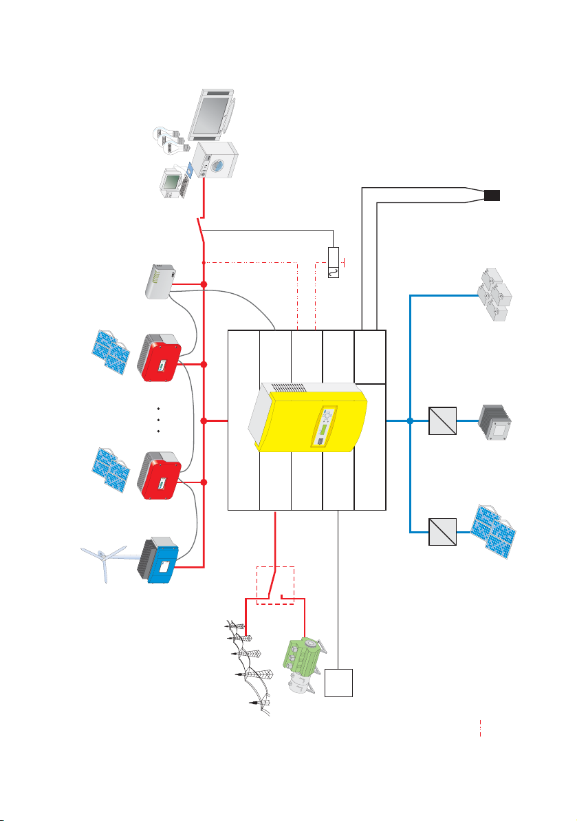
The following figure provides an overview of possible system configurations:
Loads
Batteriy
temperature sensor
Battery
Fuel Cell
*)
Can
N
TBAT
DC/DC
converter
R
E
W
O
P
M
E
SYST
T
R
O
P
E
R
Y
R
O
M
E
M
M
CO
A
M
S
M
CO
T
E
N
M
O
C
B
S
U
x
o
B
y
n
b
n
e
Sunny
u
W
S
WebBox
PV x
Sunny Boy
t
l
s
n
u
s
o
i
u
a
t
l
g
F
b
h
a
e
n
r
r
e
c
u
i
th
u
e
s
r
r
l
t
r
i
p
d
e
r
a
E
E
O
B
Stö
Fa
*)
Com
Load_S
=
d
n
y
la
n
s
n
I
u
S
=
AC Output
G_Req
DC Input
Charge-
PV
controller
=
=
PV 1
Sunny Boy
t
l
s
n
u
s
o
i
u
a
t
l
g
F
b
h
a
e
n
r
r
e
c
u
i
th
u
e
s
r
r
l
t
r
i
p
d
e
r
a
E
O
E
B
Fa
Stö
AC input
G_Ready
t
l
s
n
u
s
o
i
u
a
t
l
g
F
b
a
h
e
n
r
r
e
c
u
i
th
u
e
s
r
r
l
t
r
i
p
d
e
r
a
E
B
O
E
Fa
Stö
r
e
t
h
c
i
r
l
r
e
te
s
r
y
h
0
c
ve
e
o
n
0
i
w
g
g
0
n
n
i
i
B
r
r
t
t
s
S
y
-
3
k
c
i
i
d
a
a
t
t
R
l
l
tovo
tovo
o
o
h
h
Win
P
SW
P
Windy Boy
Start
Utility
Auto
Control voltage
*) Not included in delivery
Generator
Description:
Page 10 SI3324/4248-14:FE2406 User Manual
Page 11
SMA Technologie AG The Sunny Island 3324/4248
PE N L
PE N L
SHIELD
G_RUN-
SHIELD
G_RUN+
S_IN-
S_OUT-
S_IN+
S_OUT+
FAN+
TBAT2
FAN-
TBAT1
LOAD_S
G_REQ
LOAD_S
G_REQ
CTS
RXD
S_GND
TXD
Shield
CAN_H
C_GND
CAN_L
Equipment
Ground
DC-
Negative
DC-
Positive
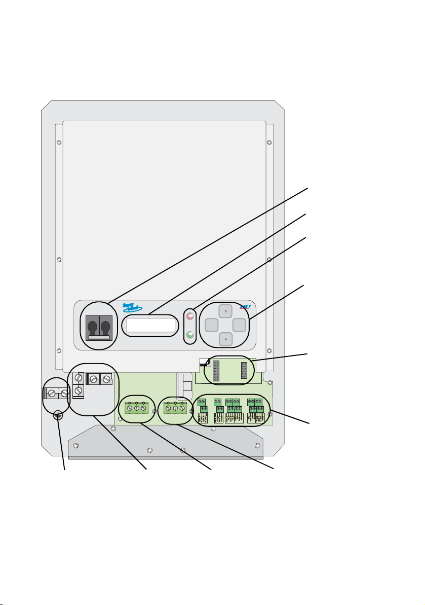
2.2 At a Glance
The following figure provides an overview of all control elements and connections of
the Sunny Island 3324/4248 (shown with cover removed).
Equipment
Ground
M
M
M
M
DC circuit
Display
LEDs showing
inverter
MMM
M
OFF
OFF
M
M
150V
200V
S5
S7
S9
S11
S13
S15
ENS2
ENS1
ENTERESC
MMM
M
operation: red
Keys
M
M
Socket for
Piggy-Back
(communication)
M
M
M
M
FAN+
CTS
Shield
RXD
CAN_H
S_GND
C_GND
TXD
CAN_L
Additional
connections (e.g.
communication,
M
M
control relays,...)
DC-
Negative
M
M
DC-
Positive
PENL
M
M
AC-OUTPUT AC-INPUT
M
M
M
M
M
M
PENL
M
M
SHIELD
S_IN-
LOAD_S
G_RUN-
S_OUT-
G_REQ
LOAD_S
G_REQ
M
M
TBAT2
SHIELD
S_IN+
FAN-
G_RUN+
S_OUT+
TBAT1
M
M
DC and AC
grounding
DC connection
(battery)
AC output
(Load)
AC input
(generator/utility)
User Manual SI3324/4248-14:FE2406 Page 11
Page 12

The Sunny Island 3324/4248 SMA Technologie AG
2.3 Accessories (optional)
The following accessories are not essential for operating a Sunny Island 3324/4248,
however they extend the range of possible applications in a stand-alone grid:
• 1 GenMan (generator manager) (SMA order number: "SI-GenMan-TFH-230")
Allows the Sunny Island 3324/4248 to control generators requiring more than a
simple start/stop (2-wire) signal for remote control.
• 1 separate load disconnecting switch for the batteries (SMA order number: "SIBattCase.01-200" for SI4248; "SI-BattCase.01-250" for SI3324)
Allows rapid, safe isolation of the Sunny Island 3324/4248 from the connected
batteries and also provides cable protection.
• 1 service cable for data transfer (SMA order number: "USBPBS-11"-USB-ServiceInterface). You also require the free "Sunny Data" software (see below).
Allows connection of a PC/laptop for communicating with the Sunny Island
3324/4248 in order to set parameters and for data read-outs.
SMA Technologie AG also offers an extensive range of products allowing you to
communicate with the Sunny Island 3324/4248, for data read-outs and much more.
Among these devices are:
• Sunny Boy Control
• Sunny Boy Control Plus
•WebBox
The "Sunny Data" and "Sunny Data Control" software, which you can use to make
settings in and read/analyze data from your inverter, can be downloaded for free
from the SMA Technologie AG website at www.SMA.de (see section 14 "Contact"
(page 65)).
2.4 SMA Products (Optional)
A stand-alone system using the Sunny Island 3324/4248 as the grid controller can
also be fed with other alternative energy sources. SMA Technologie AG offers the
following inverter products (see figure page 10):
• Sunny Boy inverters (for feeding in from PV systems): SB 700/SB 1100/
SB 1100LV/SB 1700/SB 2500/SB 2800i/SB 3000/SB 3300/SB 3800/
SMC 5000/SMC 6000/SMC 6000TL/SMC 7000TL/SMC 8000TL
Page 12 SI3324/4248-14:FE2406 User Manual
Page 13

SMA Technologie AG The Sunny Island 3324/4248
• Windy Boy inverters (for feeding in from wind turbines or hydropower systems):
WB 1100/WB 1700/WB 2500/WB 2800i/WB 3000/WB 3300/WB 3800/
WB 6000
• Hydro-Boy inverters (for feeding in from fuel cell systems)
2.5 Type Plate/Firmware Version
You can identify the Sunny Island 3324/4248 from the type plate and the firmware
version.
The type plate is located on the left side of the housing (when the Sunny Island 3324/
4248 hangs vertically on the wall bracket).
You can call up the firmware version of your Sunny Island 3324/4248 under the "312 FWVers" parameter (see section 10.4 "System and Fault Messages" (page 53)).
User Manual SI3324/4248-14:FE2406 Page 13
Page 14

The Sunny Island 3324/4248 SMA Technologie AG
Page 14 SI3324/4248-14:FE2406 User Manual
Page 15
SMA Technologie AG Safety Instructions
3 Safety Instructions
3.1 Important Notes Regarding Operation
Please follow all operating and safety instructions in this manual. Failure to follow
these instructions could result in damage to the inverter and cause personal injury.
Carefully read through the safety instructions before installing and commissioning
the inverter.
Ensure that the safety instructions and manual are stored in an easily accessible
location.
Opening the inverter, and any
• electrical installation
• repair, maintenance, or
• modification
of the Sunny Island 3324/4248 may only be performed by a
qualified electrician.
Only qualified personnel may alter the settings of the Sunny Island
3324/4248. The settings are protected by the installer password.
All of the instructions in the installation manual must be observed.
Before commissioning the Sunny Island 3324/4248, read the
instructions in the relevant sections of this operating manual
regarding the Sunny Island 3324/4248 and the batteries.
When touching the inverter, please note that some parts of the
Sunny Island 3324/4248 housing heat up during operation. These
temperatures may exceed 60°C. There is a danger of burn injury.
This inverter was NOT developed to power life-sustaining medical
devices. The Sunny Island 3324/4248 may not be used in systems
where a power outage could result in personal injury.
User Manual SI3324/4248-14:FE2406 Page 15
Page 16
Safety Instructions SMA Technologie AG
Life-threatening voltages and currents occur within the Sunny
Island 3324/4248. Protection against accidental contact is only
guaranteed if the following points are followed according to the
installation manual:
• the inverter is mounted correctly
• all connections to the inverter are made correctly
• the inverter is properly grounded
• the housing cover is subsequently securely closed
If you believe that any of these requirements are not fulfilled,
contact your installer immediately, as ignoring any of these points
may cause life-threatening personal injuries due to the voltages
present (electric shock) or may cause damage to parts of the
system.
Only qualified personnel may mount and install the battery and
the Sunny Island 3324/4248. Handling batteries is dangerous, e.g.
batteries can produce very high currents if they are short-circuited.
All of the safety instructions and general instructions in the
installation manual must be observed.
Use only rechargeable lead acid batteries. The use of other types
of battery can lead to personal injury and material damage.
Open flame or smoking in the vicinity of the battery is NOT
permitted under ANY CIRCUMSTANCES.
Take care to ensure that no metal parts fall onto the battery. This
could short-circuit the battery or other electrical components, which
could cause a fire or an explosion.
Ensure that the battery room is sufficiently ventilated.
The own consumption of the Sunny Island 3324/4248 discharges
the batteries, in standby mode (inverter DC disconnect is on,
inverter is in STOP mode and must be started manually) this load
is about 4 W and in idle mode (inverter is on, in invert mode, no
AC loads are present) it is about 22 W. You should take note of this
when operating the Sunny Island 3324/4248 for longer times
without recharge possibilities (e.g. in winter with snow on your
modules).
In these cases, you should set the Sunny Island 3324/4248 to Stop
mode (see section 9.3 "Switching Off" (S. 83)) and disconnect it
from the batteries via the DC circuit breaker.
Page 16 SI3324/4248-14:FE2406 User Manual
Page 17
SMA Technologie AG Operation / Commisioning
4 Operation / Commisioning
Before the first commissioning of the Sunny Island 3324/4248, read this "Operation"
section and become familiar with the inverter.
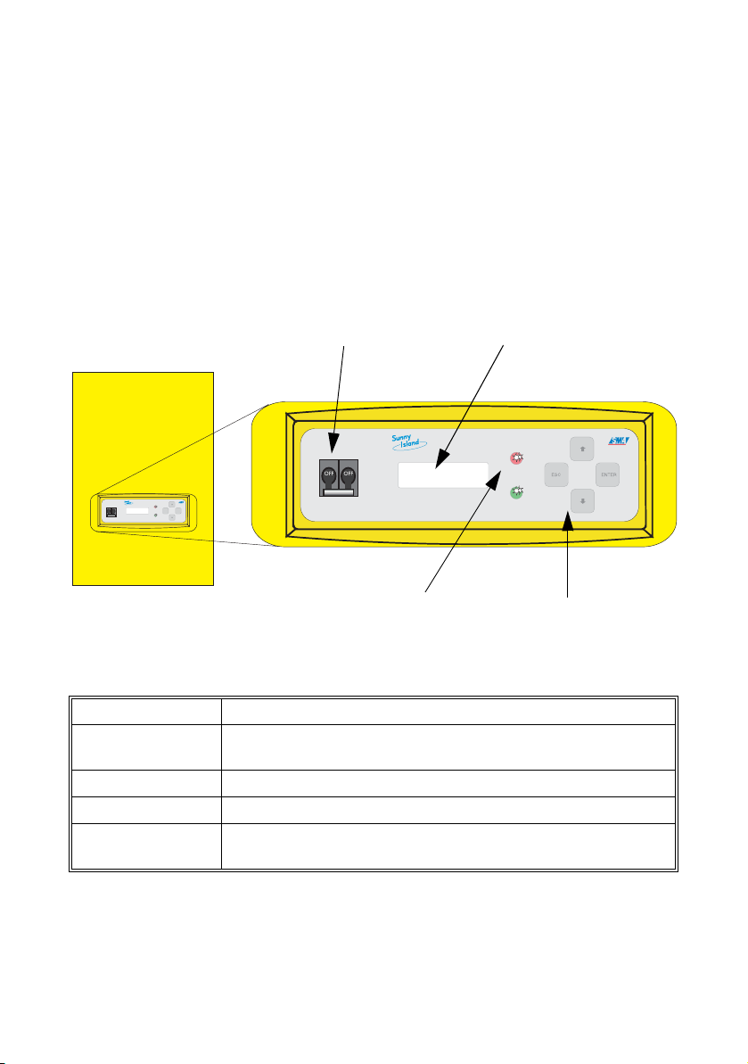
4.1 Control Elements
Functions, operating modes, parameters, data and fault messages are all displayed
in the two-line display of the Sunny Island 3324/4248. Use the arrow keys (↑ ↓), the
ESC key, and the ENTER key for navigation. The individual control elements can be
seen in the figure below.
DC circuit breaker
OFF
OFF
ENTERESC
LEDs showing
inverter operation
Display
Control keys
The following table shows the key functions:
Key Function
ESC
cancel, NO response, leave current menu, stop the inverter
(hold)
↑ navigate up one menu level, increase data value
↓ navigate down one menu level, decrease data value
ENTER
select a function, select a value, confirm changes, YES
response
The DC circuit breaker switches the Sunny Island 3324/4248 on and off. Note that
all voltage sources (batteries, (stand-alone) grid, generator) must be disconnected
from the Sunny Island 3324/4248 before the inverter is free of voltage (see section
4.2 "Activation and Deactivation" (page 20)).
User Manual SI3324/4248-14:FE2406 Page 17
Page 18
Operation / Commisioning SMA Technologie AG
4.1.1 Explanation of the Light-emitting Diodes (LEDs)
A red LED and a green LED are located on the front side of the Sunny Island 3324/
4248. The following table explains their meaning:
Green LED Red LED Operating mode
ON ON INIT (initialization phase)
— — Standby
ON — Operation
BLINKING —
Derating
(power reduction)
—ONFault
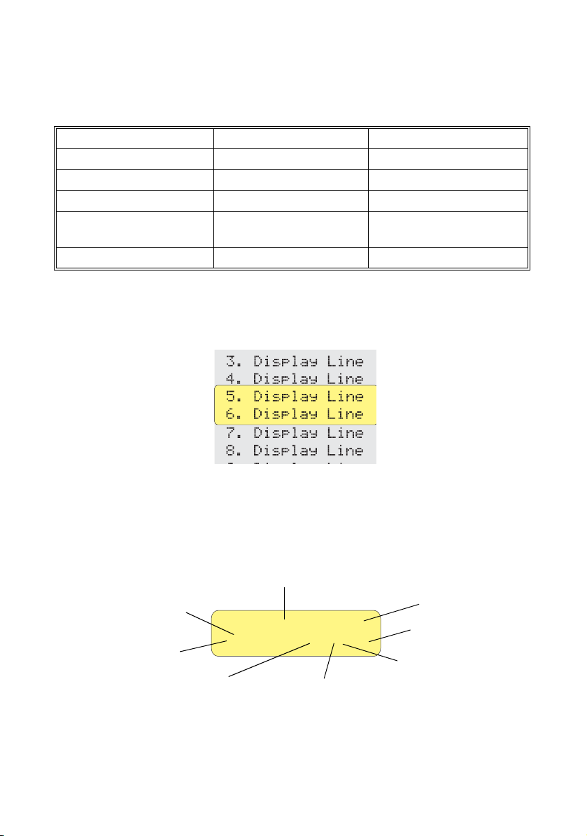
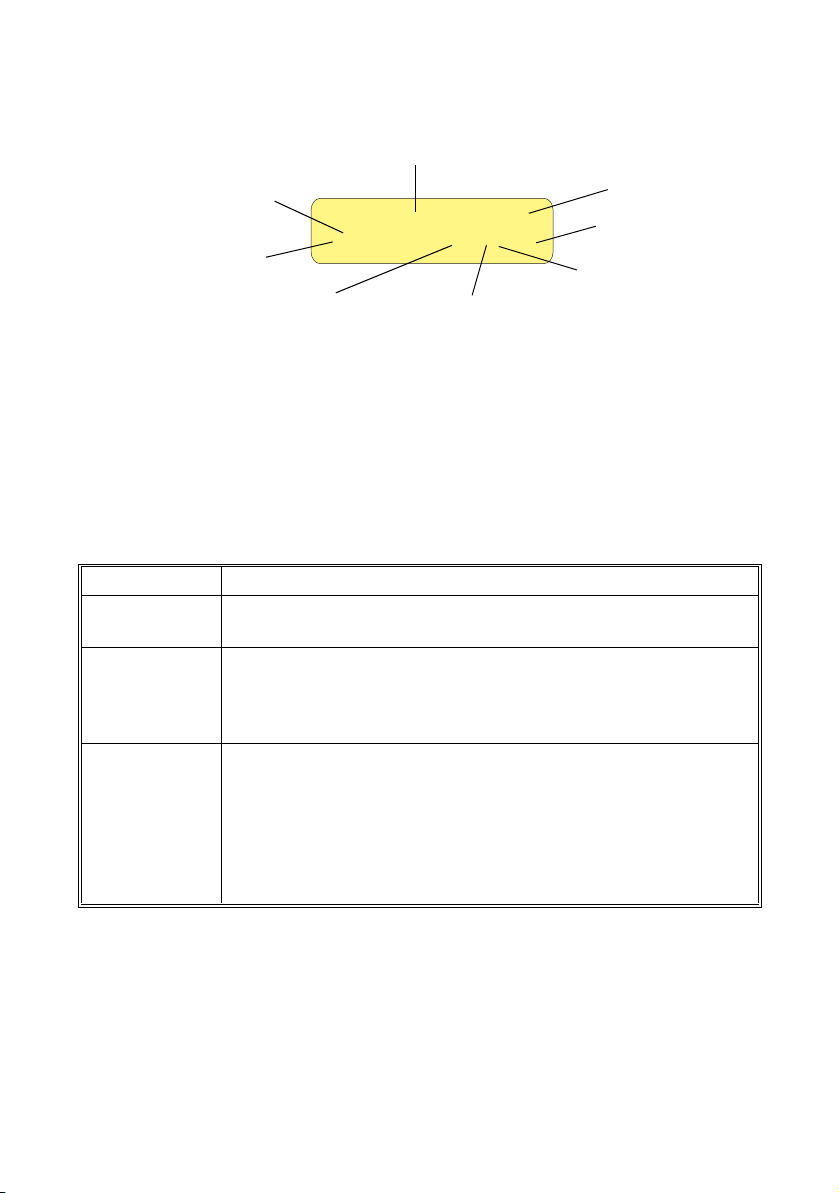
4.1.2 Display
Information about the Sunny Island 3324/4248 is shown on the two-line LCD display.
Two lines are always shown when navigating up and down the menus.
During normal operation, the Sunny Island 3324/4248 shows the relative output
power, the operating mode of the inverter, the generator status (e.g. "L" see section
4.6 "Generator Request" (page 26)), fault messages and the status of the load
shedding and generator control relay.
Output power/charging power
Operating mode
[¿¿¿¿¿¿¿¿¿¿¿¿ ]
Load status
Fault display
>Invert L oo E
Direction of energy
Generator status
Request Type
Page 18 SI3324/4248-14:FE2406 User Manual
Load shedding
relay status
Generator control
relay status
Page 19

SMA Technologie AG Operation / Commisioning
Explanation of the energy flow direction display:
">" = DC to AC (discharging mode)
"<" = AC to DC (charging mode)
Explanation of the load status display:
"]" = Normal
">" = Overload
4.1.3 Power Display
The output power and the battery charging power of the inverter are displayed by
means of the number of boxes which appear in the upper row of the display. This is
a relative indication of the inverter's output, i.e. if the boxes extend to the middle of
the scale, this shows that the Sunny Island 3324/4248 is operating at half of its
nominal output.
4.1.4 Relay Status
In the lower right-hand corner of the green display screen appear two "O"s.
Load shedding: the left "O" indicates the status of the load shedding relay of the
Sunny Island 3324/4248. "O" stands for "Off" or "Open". If the relay closes, the "O"
is filled.
Generator Start: the "O“ on the right-hand side indicates the status of the
generator control relay in the same manner. It is closed if the Sunny Island 3324/
4248 intends to start the generator.
User Manual SI3324/4248-14:FE2406 Page 19
Page 20
Operation / Commisioning SMA Technologie AG
4.2 Activation and Deactivation
4.2.1 Activation and Startup
This step assumes that the Sunny Island 3324/4248 has been
checked for
• correct connections,
•voltages and
• polarities
by your electrician, and that it has already been commissioned. If
this is not the case, have this checked by a qualified electrician!
Proceed as follows:
1. Switch on the Sunny Island 3324/4248 by switching the DC circuit breaker to
the "ON" position.
2. The Sunny Island 3324/4248 begins the
initialization phase (INIT), during which it
performs a number of self-tests to check that
there are no faults in the system.
3. You must wait for this to finish.
4. As soon as the initialization phase is finished,
the message "To start press <ENTER>" is
displayed.
5. Now press <ENTER> and the Sunny Island
3324/4248 starts up.
6. A single beep is heard. The green LED on the
control panel of the Sunny Island 3324/
4248 illuminates.
If the inverter does not display the "To start press <ENTER>" message but
displays an error message instead, this error must be corrected before the
inverter can be put into operation. For this purpose, refer to section 11
"Troubleshooting/Problem Solving" (page 55). Once all corrective measures
have been taken, switch off the Sunny Island 3324/4248, then wait for 30
seconds before starting again from point 1.
SMA SMA SMA SMA
To start
press <ENTER>
Page 20 SI3324/4248-14:FE2406 User Manual
Page 21
SMA Technologie AG Operation / Commisioning
After a successful startup, a status overview
appears in the display, showing the present
operating mode and the output power (see also
figure to the right):
You can now call up the various menus using the control elements (see section 4.1
"Control Elements" (page 17)) in order to view the measurement values and the
parameter settings.
[¿__________]
Invert oo
Waiti ng
4.2.2 Stopping
Proceed as follows to set the Sunny Island 3324/4248 to standby mode:
Note that all connected loads are no longer provided with
electrical energy once you have stopped the Sunny Island 3324/
4248.
1. Switch off all loads, as far as this is possible.
2. Press and hold the "ESC" key until the "To
stop press ENTER" message appears.
3. Press "ENTER".
4. The Sunny Island 3324/4248 stops and
enters standby mode.
To stop
press <ENTER>
5. The message "To start press <ENTER>" is
displayed. The green LED on the control
panel of the Sunny Island 3324/4248 goes
out.
Note that in standby mode there is still voltage present in the
inverter (DC, AC input).
Even in standby mode, the Sunny Island 3324/4248 still requires about 4 W
of power from the battery.
To start
press <ENTER>
4.2.3 Deactivation
To switch off the Sunny Island 3324/4248, proceed as follows:
User Manual SI3324/4248-14:FE2406 Page 21
Page 22
Operation / Commisioning SMA Technologie AG
1. Set the Sunny Island 3324/4248 to standby mode (see section 4.2.2 "Stopping"
(page 21)).
2. Switch the DC circuit breaker of the Sunny Island 3324/4248 to the "OFF"
position.
If anything is still shown on the display several seconds after switching the DC circuit
breaker, other voltage sources are active on the AC side.
Note that the Sunny Island 3324/4248 is securely deactivated only
once it has also been disconnected from all voltage sources on the
AC side. Otherwise, the inverter is NOT securely voltage-free. The
housing is not to be opened under any circumstances. For repair
work or maintenance, contact qualified electrician. Further
instructions can be found in the installation manual of the Sunny
Island 3324/4248.
To prevent possible errors, wait at least 30 seconds before switching the
inverter on again..
4.2.4 Restarting the Automatic Shutdown
To restart the Sunny Island 3324/4248 after it has switched off due to batteries that
are too deeply discharged, proceed as follows:
A complete shutdown indicates that one or more of the system
components have failed or are not working properly. Check the
components of the system for possible faults or incorrect
parameter settings before attemping to restart the system.
• Switch off the DC circuit breaker.
You must wait at least five minutes to allow the capacitors to
completely discharge before switching the DC circuit breaker on
again.
• After waiting 5 minutes switch the DC circuit breaker on again. The Sunny Island
3324/4248 runs through the INIT phase.
• Once the INIT phase is finished, the message "To start press ENTER" is displayed.
Press the "ENTER" key.
Page 22 SI3324/4248-14:FE2406 User Manual
Page 23

SMA Technologie AG Operation / Commisioning
Once the inverter is switched on again, it is important that the batteries are
charged. If an autostart generator exists in the system, the Sunny Island 3324/
4248 will start the generator after a few minutes.
• Monitor the generator start and check that the Sunny Island 3324/4248 switches
to "CHARGE" operating mode (battery charging mode).
• Check that all other energy generators in your system are also working correctly.
If the Sunny Island 3324/4248 immediately switches off with the fault
"VBatLow" (low battery voltage) after restarting, switch off all loads connected
to the AC output. The loads can be reconnected once the Sunny Island 3324/
4248 enters the "CHARGE" operating mode. (Provided that a generator
capable of providing the required power is connected to the system.)
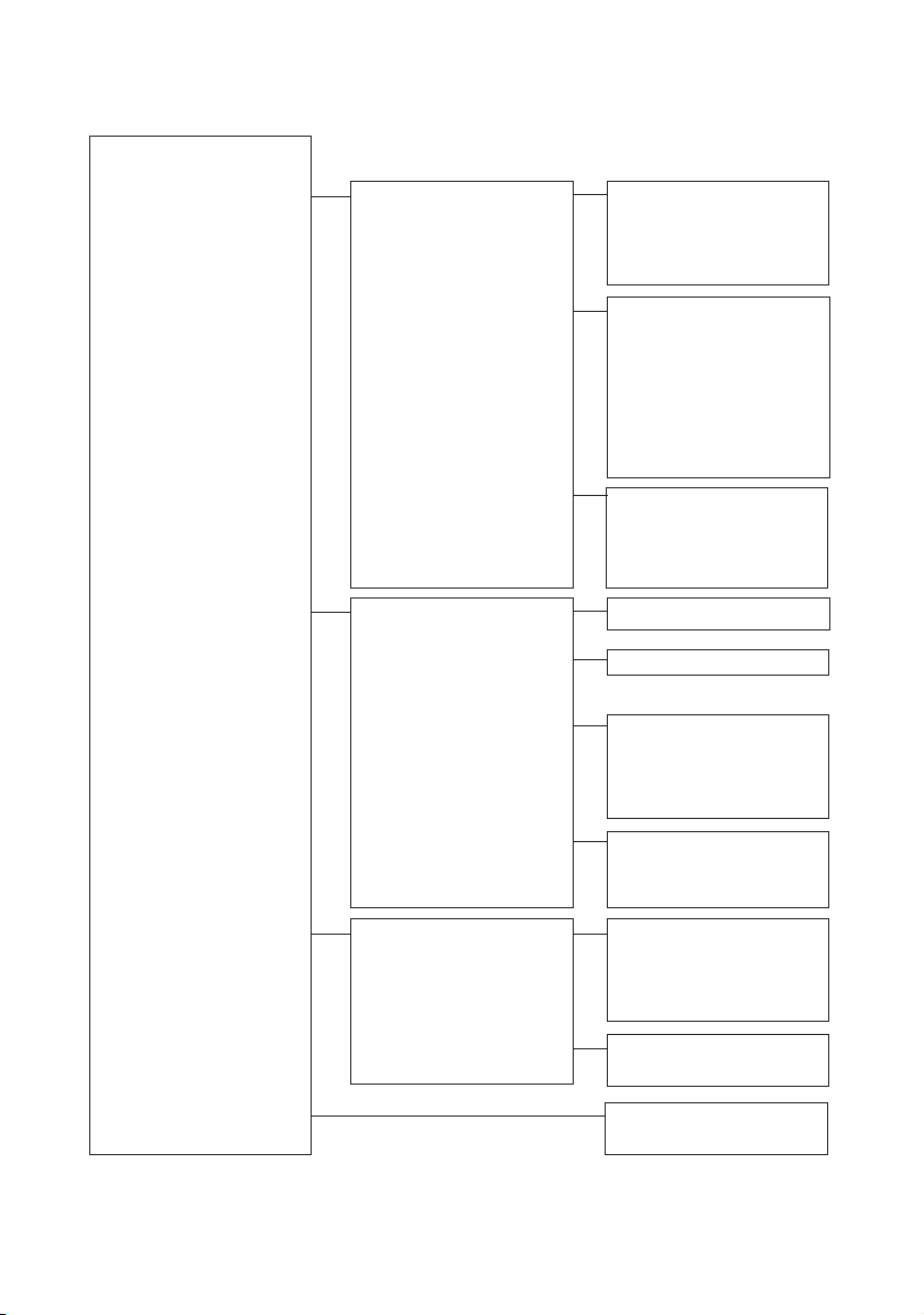
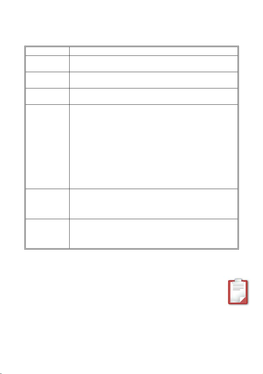
4.3 Menu Structure Overview
The main menu structure is divided into four different groups, each of which having
two subsequent submenus.
1. Meters: The "10-Meters" main menu has the following submenus: Sunny Island
3324/4248 measurements ("11-Inverter Meters"), battery measurements ("12Battery Meters") and generator measurements ("13-Generator Meters").
Individual measurement values can be seen in the next two menu levels.
2. Settings: Under the main menu "20-Settings" are four different submenus
allowing various system parameters to be viewed and changed. This affects
password entry ("21-Password Settings") and all system parameters relating to
the Sunny Island 3324/4248 ("22-Inverter Settings"), the batteries ("23-Battery
Settings") and the generator ("24-Generator Settings").
3. Diagnose: Under the main menu "30-Diagnose" are two different submenus
allowing various diagnostic parameters to be viewed. These are system data
("31-System Information"), and fault messages ("32-Error Information").
4. Operation: The main menu "40-Operation" allows viewing and changing of
the operating parameters (e.g. "40-8 SunnyBoys").
Please consult section 4.1.1 "Explanation of the Light-emitting Diodes (LEDs)"
(page 18) for information describing how to set the individual parameters.
You will find a tabular list of all parameters in section 10 "Parameter Lists" (page 47).
User Manual SI3324/4248-14:FE2406 Page 23
Page 24
Operation / Commisioning SMA Technologie AG
Home Screen
10 METERS
20 SETTINGS
11 Inverter Meters
12 Battery Meters
13 Generator Meters
21 Password Settings
22 Inverter Settings
23 Battery Settings
11-1 VacInverter
11-2 AmpacInverter
11-3 FacInverter
11-4 PacInverter
12-1 BatVoltage
12-2 BatCurrent
12-3 BatTemp
12-4 BatState
12-5 BatChargeMode
12-6 TabsorbLeft
12-7 BatChargeVolt
13-1 VacGenerator
13-2 AmpacGenerator
13-3 FacGenerator
13-4 PacGenerator
21-1 Level [00] *****
22-1 VacNominal
23-1 VdcBatNominal
23-2 BatType
23-3 AmpHoursBat
23-4 AmpdcBatMax
24 Generator Settings
24-1 GenControl
24-2 AmpacGenMax
24-3 GenOperation
30 DIAGNOSE
31 System Information
31-1 DeviceConfig &
31-2 FWVERS
31-3 SerNum
31-4 RunTime
32 Error Information
32-1 Last
32-2 Hist
40 OPERATION
40-1 BatChargeMode
40-2 Autostart
Page 24 SI3324/4248-14:FE2406 User Manual
Page 25

SMA Technologie AG Operation / Commisioning
4.4 Viewing and Altering Parameters
Use the <ENTER> key to open a menu. Use the ↑ (upwards) or ↓ (downwards) keys
to navigate through the selected menu (see the "Menu structure" diagramm in section
4.3 "Menu Structure Overview" (page 23)) in order to view or change parameter
values. As soon as the desired parameter appears in the display, you can read the
current parameter value.
The display always shows the first two digits of a
parameter. The menu structure and the
assignment of parameters are explained in
section 4.3 "Menu Structure Overview"
(page 23).
An "Enter" arrow is displayed next to parameters
which you are able to alter .
Note that some parameters can only be changed
when the inverter is in standby mode (see section
4.2.3 "Deactivation" (page 21)). You can find the parameters for which this applies
in the tables in section 10.3 "Adjustable System Parameters" (page 51) and
section10.5 "Operation (Operation)" (page 54).
If you press the <ENTER> key, the "Enter" arrow begins to blink and you can then
use the arrow keys (↑ or ↓) to change the current parameter value.
As soon as the desired value appears in the display, press the <ENTER> key to save
the new value, or press the <ESC> key to discard the changes and exit the menu.
If you wish to exit the current menu level (e.g. "24-3 GenOperation" parameter) then
press the <ESC> key. In this example, the cursor then jumps back to the "23-Battery
Settings" menu level.
On-screen display of e.g.
parameter
"24-3 GenOperation“:
GenOperation ‹24
Auto ↵
4.5 Operating Modes
The operating modes are shown on the left-hand side of the display. The operating
modes are:
• Invert: Inverter operation (no generator or public grid present)
• Charge: Charging (batteries are being charged by the generator or the public
grid)
• DerInvert: Inverter operation with reduced power due to voltage reduction
• DerCharge: Charging with reduced power due to current reduction
• Silent: Energy-saving mode
User Manual SI3324/4248-14:FE2406 Page 25
Page 26
Operation / Commisioning SMA Technologie AG
4.6 Generator Request
Operating mode
Direction of energy
flow
Generator status
Output power/charging power
[¿¿¿¿¿¿¿¿¿¿¿¿ ]
>Invert L oo E
Request Type
Load shedding
relay status
Load status
Fault display
Generator control
relay status
In the Sunny Island 3324/4248 display, it is possible to read whether and why the
generator is working. Some of the generator menu parameters mentioned here can
only be viewed or altered after entering the installer password.
More detailed descriptions regarding the generator can be found in section 5
"Generator Settings" (page 29) of this user manual, or in the installation guide of the
Sunny Island 3324/4248.
The following table describes the status of the generator voltage and generator
frequency, as they are shown in the display:
Display Description
*
The generator voltage and frequency lie within the defined limits
(see Generator Settings: parameters 24-4 to 24-8, installer level).
The generator voltage and/or frequency lie outside the defined
?
limits (see Generator Settings: parameters 24-4 to 24-8, installer
level). The Sunny Island 3324/4248 will not connect the
generator to the stand-alone grid while this situation exists.
The maximum permissible generator reverse power ("24-11
PGenReverse" parameter, installer level) has been exceeded. The
Sunny Island 3324/4248 has removed the generator from the
!
stand-alone grid. The generator cannot be reconnected to the
stand-alone grid for a period of 20 minutes. This lockout can be
removed by setting the "24-3 GenOperation" parameter to
"Release".
Page 26 SI3324/4248-14:FE2406 User Manual
Page 27
SMA Technologie AG Operation / Commisioning
The following table provides information as to the reasons why the generator is being
requested. One of the following six letters will appear in the display:
Display Description
B(attery)
H(eat)
L(oad)
The generator has been requested as a result of the battery
management system.
The generator has been started as a result of a temperature
dependent request.
The generator has been started as a result of a load dependent
request.
The generator was started for one of the following reasons:
• The user directly started the generator.
• The user switched the (optional) GenMan switch to "ON".
• The GenMan automatically started the generator due to a too
R(emote)
low starter battery voltage.
• The Sunny Island 3324/4248 automatically switches to an
external voltage source (displayed in backup systems, as long
as the public grid is present).
In all three situations the Sunny Island 3324/4248 CANNOT start
or stop the generator but may charge the batteries if required.
The generator is requested by the user manually setting the
S(tart)
generator request in the Sunny Island 3324/4248 from "Auto" to
"Start". The generator is then NO LONGER controlled or switched
off by the Sunny Island 3324/4248.
The generator was started for one hour using the "Run1h" setting
T(ime)
in the Sunny Island 3324/4248. Once this time has passed, the
Sunny Island 3324/4248 automatically switches off the
generator.
The generator status and the reason for the request are shown (alternating) in the
"Generator status" in the display.
If (e.g.) the display changes every 2 seconds from "*" to "B" then this means
that the generator voltage and frequency lie within the specified limits and that
the generator was requested by the battery management system.
If the generator has been manually set to "Stop" then no generator status information
is shown in the display. The field remains empty.
User Manual SI3324/4248-14:FE2406 Page 27
Page 28

Operation / Commisioning SMA Technologie AG
4.7 Fault Detection
If the Sunny Island 3324/4248 detects a fault, it displays the corresponding error
code in the display for ten seconds. The error is added to the list in the error menu,
and an "E" (for error) is displayed in the lower right-hand corner of the green display
screen. The "E" is displayed until the user has checked the error in the error menu.
Once the error has been checked, the "E" disappears from the screen.
The list of errors comprises ten errors, and remains intact even if the Sunny Island
3324/4248 is deactivated. If more errors occur, the oldest error in the list is
overwritten. The error which was added most recently is marked with an arrow.
Page 28 SI3324/4248-14:FE2406 User Manual
Page 29

SMA Technologie AG Generator Settings
5 Generator Settings
5.1 Generator Types
In stand-alone grid systems, (diesel) generators are often used. Choosing the right
generator is heavily dependent on the system's operating conditions. There are two
basic generator categories:
• those which can be started and stopped via electrical contacts autostart generators
• those which can only be operated manually "manual-start" generators
5.1.1 Autostart Generators
The basic function of an autostart generator is to start up and run without intervention
from the system operator. To achieve this, the generator, in addition to executing the
startup process independently, must also arrange warm-up times, cool-down times,
minimum run times and minimum stop times.
This type of generator is recommended for use in conjunction with a Sunny Island
3324/4248. Please contact your installer or system manufacturer for
recommendations regarding a specific generator.
5.1.2 Manual-Start Generators
Generators which are activated manually need to be started by the user by means
of a button or other activation procedure. These generators are structured more
simply, and generally cost less.
Both types of generators can produce electricity. Select your generator
carefully. If in doubt, please contact appropriate qualified personnel.
5.2 Generator Parameters
If you wish to use a generator with the system, then you must set the generator type,
the type of generator connection and the maximum output current delivered by the
generator. To reach the generator menu, start in the main menu (Home Screen) and
use the arrow keys to scroll to Settings (20), then press Enter and scroll to the
Generator Settings (24) menu. In this menu, you can change all parameter values
relating to a connected generator.
You require the installer password in order to set parameters "24-4 to 24-16".
User Manual SI3324/4248-14:FE2406 Page 29
Page 30

Generator Settings SMA Technologie AG
The following section describes the settings for the following particularly important
commissioning parameters in detail:
• "24-1 GenControl" - Selection of the generator type
• "24-2 AmpacGenMax" - Max. generator output current
• "24-3 GenOperation" - Generator request
All adjustable parameters of the Generator Settings are listed in tabular form in
section 10.3 "Adjustable System Parameters" (page 51).
5.2.1 Selection of Generator Control Method
Use "24-1 GenControl" parameter to select the type of generator to be used in your
system. Three settings are possible:
1. "Manual" Setting (Factory Setting)
"Manual" should be selected when
• no generator is installed in the system or
• the connected generator can only be manually started (directly at the generator).
As soon as a voltage at the AC input terminals (generator connection) of the Sunny
Island 3324/4248 is within the parameter limits (see parameter 24-2 and 24-4 to 24-
7), the Sunny Island 3324/4248 connects to the generator.
The parameter settings are intended for generators that cannot be automatically
started. Since in these cases the Sunny Island 3324/4248 GenRequest relay is not
used for directly starting the generator, it can here provide a signal transmitter for
the stand-alone grid user.
A signal light can be connected to the "GenRequest" contact that signals the
stand-alone grid user to start the generator when this is required. The signal
light is then switched off again via the "GenRequest" contact when the
generator is no longer needed. Note that, with these settings, although the
signal light has gone out the Sunny Island 3324/4248 will not automatically
disconnect from the generator. You must stop the generator manually.
Possible reasons for a generator request are:
• A request by the battery management (low battery voltage)
• A request by the load-dependent generator management (to handle generator
peak loads)
• A request by the temperature-dependent generator management (to protect the
Sunny Island 3324/4248 against overload)
2. "Direct" Setting
Page 30 SI3324/4248-14:FE2406 User Manual
Page 31

SMA Technologie AG Generator Settings
If the system uses a generator that can be automatically started using a contact (twowire autostart generator directly connected to the Sunny Island 3324/4248), set this
parameter to the "Direct" setting. The closing of the GenRequest relay (see the
installation manual for connection information) provides the start command to the
generator from the Sunny Island 3324/4248. When the generator is no longer
required, the start contact opens and the start command is revoked.
Possible reasons for a generator start command are:
• A request by the battery management (low battery voltage)
• A request by the load-dependent generator management (to handle generator
peak loads)
• A request by the temperature-dependent generator management (to protect the
Sunny Island 3324/4248 against overload)
• Manual start of the generator by the user via setting the
"24-3 GenOperation" parameter to the value "Start" or "Run1h"
Note that in this configuration the Sunny Island 3324/4248 will only connect
the generator when it requested the generator by closing the "GenRequest"
contact.
If you wish to start the generator manually, activate the generator using the
"24-3 GenOperation" parameter.
3. "GenMan" Setting
The "GenMan" setting must be used for all generators that require more than a single
contact for starting. In addition to setting the parameter, the generator must also be
integrated into the system using the (optional) GenMan device - SMA order number
'SI GenMan' . Information on installation and parameter settings can be found in the
GenMan handbook.
The reasons for a generator request from the Sunny Island 3324/4248 are the same
as those listed under "Direct" with these two exceptions:
• The Sunny Island 3324/4248 will only connect the generator when the "GenRun"
signal from the GenMan unit is received indicating that the generator is ready.
• With this setting it is not absolutely necessary that the inverter itself has set the
"GenRequest" relay before it connects the generator. In normal operation, the
inverter will usually set the "GenRequest" relay to request the generator and then
connect the generator once the "GenRun" signal has been received from the
GenMan. The decisive signal for connecting the generator is however the
"GenRun" signal. This allows the generator to be manually started at the
GenMan.
User Manual SI3324/4248-14:FE2406 Page 31
Page 32

Generator Settings SMA Technologie AG
5.2.2 Setting the Output Current Limit
The "24-2 AmpacGenMax" parameter helps to prevent the generator from
overloading or stalling. The Sunny Island 3324/4248 will (e.g.) reduce the battery
charging current in charging mode ("Charge" mode) so that the total generator load
does not exceed the value defined in this parameter. In inverter mode ("Invert"
mode) the Sunny Island 3324/4248 will only connect the generator when the load
lies below the value defined here, even if the generator was requested.
To make the best use of the run time and service life of the generator, the value here
should be set to about 85 % of the nominal generator current. Please refer to the
generator manufacturer's recommendations.
5.2.3 Generator Request
The user can use the "24-3 GenOperation" parameter to start the generator directly.
Only use the settings 1 — 4 when you have set the "24-1 GenControl" parameter (see
section 5.2.3 "Generator Request" (page 32)) to "Direct" or "GenMan".
Setting 5 ("Release") is also useful under the "Manual" setting.
Five different settings are possible for the "24-3 GenOperation" parameter. Take
note of the messages in the display (see section 4.6 "Generator Request" (page 26)):
1. "Auto" Setting (Factory Setting)
In this configuration, the Sunny Island 3324/4248 will automatically control the
generator and start and stop it as needed.
2. "Start" Setting
This setting causes an immediate generator request. The "Start" setting is indicated by
an "S" in the display (see section 4.6 "Generator Request" (page 26)).
The Sunny Island 3324/4248 can not automatically stop the
generator when you have started it using the "Start" setting.
Do not forget to stop the generator when you no longer need it.
To do this, set the "24-3 GenOperation" parameter to "Stop" or
"Auto".
Page 32 SI3324/4248-14:FE2406 User Manual
Page 33

SMA Technologie AG Generator Settings
3. "Stop" Setting
This setting immediately stops the generator, as long as the "24-1 GenControl"
parameter is set to "Direct" or "GenMan".
The Sunny Island 3324/4248 can not start the generator and will
not connect an externally started generator if you have switched
it off using the "Stop" setting.
Remember to reset the "24-3 GenOperation" parameter back to
"Auto" if the Sunny Island 3324/4248 should assume control of the
generator.
Please also note that a generator stopped using the "Stop" setting
can also be started by other components in the stand-alone
system. For example, the GenMan independently starts the
generator as soon as the generator starter battery voltage sinks
below a particular value.
4. "Run1h" Setting
This parameter setting can be useful when the batteries should be relieved by the
generator for a foreseeable period of time. As soon as the "24-3 GenOperation"
parameter is set to "Run1h", the generator is requested for a period of one hour. The
"Run1h" setting is indicated by a "T" in the display (see section 4.6 "Generator
Request" (page 26)).
After one hour has passed, the Sunny Island 3324/4248 automatically sets the "243 GenOperation" parameter back to "Auto".
Exception:
If "Run1h" was selected from the "Stop" mode, after one hour the Sunny Island
3324/4248 returns to this mode (see also 3. "Stop" Setting).
5. "Release" Setting
The "Release" setting releases the 20 minute lockout time triggered when the reverse
power limits are exceeded.
The "24-11 PGenReverse" parameter limits the power that may be fed back into the
generator for up to five seconds.
If the reverse power exceeds this value then the generator/grid is disconnected and
the Sunny Island 3324/4248 switches to stand-alone grid operation. The generator
or grid cannot now be reconnected for a period of 20 minutes. Setting the "24-3
GenOperation" parameter to "Release" removes this lockout. After "Release" has
User Manual SI3324/4248-14:FE2406 Page 33
Page 34

Generator Settings SMA Technologie AG
been activated, the "24-3 GenOperation" parameter is automatically reset to the
"Auto" value and the Sunny Island 3324/4248 can again synchronize to the public
grid or the generator.
Page 34 SI3324/4248-14:FE2406 User Manual
Page 35
SMA Technologie AG Battery Management
6 Battery Management
The service life of batteries in off-grid applications can vary greatly. With proper
handling the batteries can last as long as 15 years. The main causes of premature
aging are incorrect charging and frequent deep discharge. For these reasons, the
Sunny Island 3324/4248 has an intelligent charge control and reliable deep
discharge protection. When these features are properly used, the battery service life
can be greatly extended in comparison with simpler devices.
All types of lead acid batteries are supported. The battery management system
draws a distinction between sealed lead acid batteries with liquid electrolyte (FLA,
Flooded Lead Acid) and the sealed lead acid batteries with semi-solid electrolyte
(VRLA, Valve Regulated Lead Acid). All Gel and Absorbed Glass Mat batteries
belong to the last group (AGM, Absorbent Glass MateSeparator).
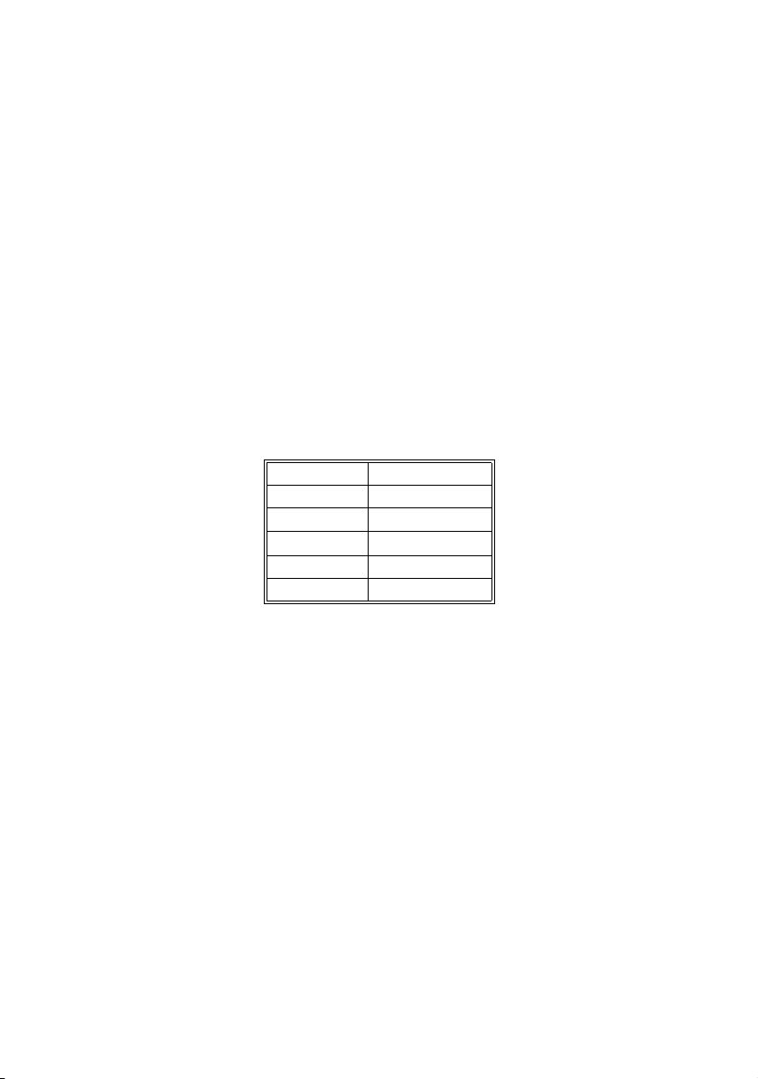
The battery capacity is to be entered as the nominal capacity for a ten hour discharge
(C10). If this is not available from the battery manufacturer's data sheet, then
calculate this from the data for different discharge times (120 h, 100 h, 20 h, 5 h,
1 h) in the following manner:
C10 C120/1.28
C10 C100/1.25
C10 C20/1.09
C10 C10
C10 C5/0.88
C10 C1/0.61
User Manual SI3324/4248-14:FE2406 Page 35
Page 36

Battery Management SMA Technologie AG
6.1 Charge Control
The Sunny Island 3324/4248 has a 3-level charge control using the IV0V process.
The I stands for the bulk phase. At this level, the charging is only limited by the
defined maximum battery current ("23-4 AmpdcBatMax" parameter) or by the
maximum generator current ("24-2 AmpacGenMax" parameter). During this phase
the battery voltage increases as the batteries are charged.
Once the battery voltage has reached the value defined for the second phase V
then the constant voltage charging (absorption phase) begins. At this level, the
battery voltage is maintained at a constant level, resulting in a continually decreasing
battery current. The Sunny Island 3324/4248 remains in this phase for the period of
time defined for this phase (parameters "12-6 TabsorbLeft").
Once this phase is finished, the Sunny Island 3324/4248 enters the float charge that
again provides constant current charging but at a greatly reduced charging voltage.
If charging is done from a generator, then this is stopped on entry to this phase, thus
ending charging of the batteries at this point. The Sunny Island 3324/4248 remains
in this phase until either more than 30 % of the nominal capacity has been used (all
discharges are summed) or the generator is automatically restarted (see section 5.2
"Generator Parameters" (page 29)).
Page 36 SI3324/4248-14:FE2406 User Manual
,
0
Page 37

SMA Technologie AG Battery Management
For the second charging level V0, the constant voltage charging (absorption phase)
for a limited period of time, the Sunny Island 3324/4248 automatically chooses
between three different voltages and charging times. These are the boost charge, full
charge and equalizing charge. The following figure shows a process diagram of the
charging process.
TcycleEquals days or 16
charging throughputs
TcycleEquals days or 30
charging throughputs
Equaliziation
V = VchargeEqual
V > VchargeEqual
for TabsorbEqual
Boost Charge
V = VchargeBoost
Floating Charge
V = VchargeFloat
Silent Mode
Bms Silent Request = on
TcycleFull days or
8 charging throughputs
Full Charge
V = VchargeFull
V > VchargeFull
for TabsorbFull
The Sunny Island 3324/4248 most often chooses the boost charge in order to bring
the batteries to a reasonable level in a short period of time. This process is optimized
to keep the generator run times as short as possible.
The Sunny Island 3324/4248 initiates a full charge every 14 days or after every
eight charging throughputs, with the aim of fully recharging the batteries to remove
any negative effects caused by insufficient charging. Various studies have shown that
regular full charging every two to four weeks can double the battery service life in
off-grid systems.
A battery bank consists of many series-connected individual battery cells (2 V each),
each of which having a slightly different behavior. Over time, this results in different
charge levels of the individual cells. This can lead to premature failure of first single
cells and then failure of the entire bank.
User Manual SI3324/4248-14:FE2406 Page 37
Page 38

Battery Management SMA Technologie AG
For this reason, the Sunny Island 3324/4248 automatically performs regular
equalization charging every 60 days or after every 30 charging throughputs. The
equalization charging uses controlled overcharging of the battery bank to ensure
that even the weak cells are fully charged. Equalization charging leads to a further
significant increase of battery service life by a factor of up to 50 %.
The charging capability of lead acid batteries is heavily dependent on the battery
temperature. For temperatures below 20°C the charging voltage must be slightly
increased, and for temperatures above 20°C it must be slightly reduced. This is
necessary to avoid overcharging and insufficient charging at all battery
temperatures. For this reason, the Sunny Island 3324/4248 is equipped with
automatic temperature compensation of the charging voltage. At temperatures
below 20°C, the charging voltage is raised by 4 mV/°C and cell (96 mV/°C for a
48 V battery) and reduced by the same amount at temperatures above 20°C. The
maximum permissible battery temperature is also monitored and the system switches
off with a fault if the limit is exceeded ("23-18 TBatMax" parameter).
6.2 Silent Mode
When operating with the public grid, in addition to the float charge a silent mode
exists. The main purpose of the silent mode is to save energy in backup systems,
where the Sunny Island 3324/4248 spends most of the time in the float charge mode
by switching from charging mode to silent mode.
Silent mode is automatically activated when the float charge charging power drawn
from the grid and flowing into the batteries is less than 40 W. In this case, one can
assume that the batteries are 100 % charged and that further charging is not
required in the next few hours.
The float charging is automatically reactivated either after twelve hours or when the
battery voltage sinks below 50.2 V. This ensures that the batteries are always fully
charged, even in silent mode. If a power failure occurs during silent mode, the Sunny
Island 3324/4248 switches to invert mode within a few milliseconds. The loads are
supplied almost without interruption.
Page 38 SI3324/4248-14:FE2406 User Manual
Page 39
SMA Technologie AG Battery Management
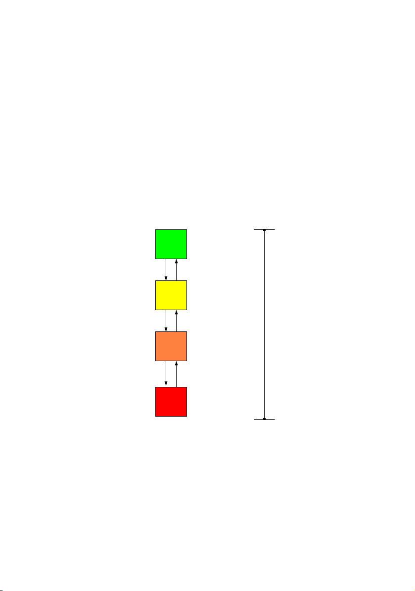
6.3 Deep Discharge Protection / Battery State
When deeply discharged, lead acid batteries age 100 times more quickly than when
fully charged. Depending on the battery type, one speaks of deep discharge at
charge levels of less than 40 %. Reliable protection from deep discharge is essential
for a long battery service life. The Sunny Island 3324/4248 uses currentcompensated voltage thresholds combined with time delays for deep discharge
protection. The different levels, which can be easily set, are used to define the four
state of the batteries (BatState):
• Normal operation (BatState = Normal)
• 1st level (BatState = Warning)
• 2nd level (BatState = Low)
• 3rd level (BatState = Critical)
The following figure shows the four battery states:
100 %
Normal
BatVoltage, BatCurrent <
for t > 2/6/30 minutes
BatVoltage, BatCurrent <
SocLim2 for t > 2/6/30
BatVoltage, BatCurrent <
for t > 2/6/30 minutes
and no charging current
SocLim1
minutes
SocLim1
BatVoltage, BatCurrent >
SocLim1
for t > 15 minutes
Warning
(Start
Generator)
BatVoltage, BatCurrent >
SocLim2
for t > 15 minutes
Low
(Load
Shedding)
BatVoltage, BatCurrent >
SocLim3
for t > 15 minutes
or charge current
Critical
(Shut
down)
SocLim1
SocLim2
SocLim3
0 %
As long as the Sunny Island 3324/4248 has not detected a deep discharge then it
is in the battery state (BatState) Normal.
As soon as the first level of deep discharge is reached, the Sunny Island 3324/4248
switches to the Warning state. This can be used to start a generator.
If the batteries are further discharged despite the warning, then the battery state now
jumps to the next deep discharge level Low. If desired, this level can be used to
trigger the Sunny Island 3324/4248 relay contact to switch off all or some of the
loads.
User Manual SI3324/4248-14:FE2406 Page 39
Page 40

Battery Management SMA Technologie AG
If this is not done and the batteries are still further discharged then the battery state
reaches the last level Critical.
If no charging current flows into the batteries within five minutes of entering this state,
then the Sunny Island 3324/4248 automatically switches to standby mode to avoid
any further deep discharge.
If the battery voltage does not recover within 30 minutes, then the Sunny Island
3324/4248 switches completely off. A complete switch-off can be recognized by the
fact that the DC circuit breaker is switched on but the display remains dark and no
voltage is present at the AC output terminals.
Once fully switched off, the Sunny Island 3324/4248 can only be manually restarted
(see section 4.2.4 "Restarting the Automatic Shutdown" (page 22)).
Page 40 SI3324/4248-14:FE2406 User Manual
Page 41

SMA Technologie AG Frequency Shift Power Control (FSPC)
7 Frequency Shift Power Control (FSPC)
This section describes how the power adjustment via frequency "Frequency Shift
Power Control (FSPC)" functions.
If Sunny Boy inverters are connected to the AC output side of a stand-alone grid, the
Sunny Island 3324/4248 must be able to limit their output power. This situation can
occur when (e.g.) the Sunny Island 3324/4248 batteries are fully charged and the
(solar) power available from the PV generator exceeds the power required by the
connected loads.
To prevent the excess energy from overcharging the batteries, the Sunny Island
3324/4248 recognizes this situation and changes the frequency of the AC output.
This frequency adjustment is analyzed by the Sunny Boy. As soon as the grid
frequency increases beyond the value specified by "Fac-Start delta" the Sunny Boy
limits its output power accordingly.
This function is shown in the following figure:
The frequency increase is 5 Hz maximum, starting at the nominal frequency f
.
0
When FSPC is activated and the generator is operating in the stand-alone grid, the
generator determines the frequency and the Sunny Boys react to changes in the
generator frequency. Generators normally operate at 50 Hz under load. For this
reason, in most cases the Sunny Boys will deliver their entire power to the stand-alone
grid, even when the generator is running.
User Manual SI3324/4248-14:FE2406 Page 41
Page 42

Frequency Shift Power Control (FSPC) SMA Technologie AG
Page 42 SI3324/4248-14:FE2406 User Manual
Page 43

SMA Technologie AG Automatic Frequency Adjustment
8 Automatic Frequency Adjustment
Clocks that depend on the stability of the grid frequency for their accuracy, become
increasingly inaccurate when subjected to constant frequency deviations. Frequency
fluctuations, i.e. deviations from the nominal frequency (50 Hz) often occur in (e.g.)
stand-alone grids that work with a generator.
The "Automatic FRequency Adjustment (AFRA)" function of the Sunny Island 3324/
4248 allows the use of grid-coupled clocks in these types of stand-alone systems.
By counting all positive zero-crossing points (full waves) at the inverter output of the
Sunny Island 3324/4248, in both battery charging operation and inverter
operation, the inverter constantly measures the actual frequency. These values are
compared with the desired frequency values every twelve hours. If a time difference
of five seconds or more exists then a frequency increase or -decrease is activated.
This frequency adjustment remains active if the time difference is more than one
second.
User Manual SI3324/4248-14:FE2406 Page 43
Page 44

Automatic Frequency Adjustment SMA Technologie AG
Page 44 SI3324/4248-14:FE2406 User Manual
Page 45

SMA Technologie AG Maintenance and Care
9 Maintenance and Care
The Sunny Island 3324/4248 has been constructed for low maintenance. Thus, the
necessary work is limited to only a few points:
9.1 Housing
Check that the Sunny Island 3324/4248 housing is mechanically sound. If damage
(e.g. cracks, holes, missing covers) endangers the operating safety, the Sunny Island
3324/4248 must be deactivated immediately.
Larger particles of dirt should be removed from the inverter with a soft brush, or
similar object. Dust can be removed with a damp cloth. Solvents, abrasives or
corrosive materials must not be used for cleaning!
9.2 Cleaning the Fans
The cleaning intervals depend on the ambient conditions. We recommend inspecting
the filters at least once a month.
If the fans are covered with loose dust, you can clean them with the aid of a vacuum
cleaner (recommended) or a soft brush. Clean the fans only when at a standstill. If it
is necessary to replace the fans, please contact your installer.
9.3 Display
It is best to clean the control elements with a soft, damp cloth. Solvents, abrasives or
corrosive materials must not be used for cleaning!
Take care not to accidentally press the membrane keys during
cleaning. Either clean the membrane keypad when the inverter is
deactivated, or make sure that the password protection is active.
User Manual SI3324/4248-14:FE2406 Page 45
Page 46

Maintenance and Care SMA Technologie AG
9.4 Functioning
Check regularly whether error messages are present. If an error message is
displayed, for which you cannot identify any apparent cause, the stand-alone grid
must be inspected by a qualified electrician. To ensure optimal operation, the
operator should regularly check the entries in the Sunny Island 3324/4248 error list
at short intervals (monthly, or even weekly), especially during the first months after
commissioning. This can help to discover hidden faults in the installation or errors in
the configuration.
9.5 Battery
The battery must be checked and maintained regularly. In this
regard, observe the battery manufacturer's specifications.
Page 46 SI3324/4248-14:FE2406 User Manual
Page 47

SMA Technologie AG Parameter Lists
10 Parameter Lists
The following tables contain information regarding all menu items to which the Sunny
Island 3324/4248 user has access.
There are other measurement values and parameters additional to those shown here,
but which are to be set by qualified personnel. Only once the installer password has
been entered, can these measurement values and parameters be viewed and
altered. This is described in the Sunny Island 3324/4248 installation manual.
Please proceed carefully when changing parameter settings, because incorrect
settings can lead to faulty operation of the inverter.
Take note of the previous value of each parameter before you change it!
10.1 Menu Structure Overview
The main menu structure is divided into four different groups, each of which having
two subsequent submenus.
1. Meters: The "10-Meters" main menu has the following submenus: Sunny Island
3324/4248 measurements ("11-Inverter Meters"), battery measurements ("12Battery Meters") and generator measurements ("13-Generator Meters").
Individual measurement values can be seen in the next two menu levels.
2. Settings: Under the main menu "20-Settings" are four different submenus
allowing various system parameters to be viewed and changed. This affects
password entry ("21-Password Settings") and all system parameters relating to
the Sunny Island 3324/4248 ("22-Inverter Settings"), the batteries ("23-Battery
Settings") and the generator ("24-Generator Settings").
3. Diagnose: Under the main menu "30-Diagnose" are two different submenus
allowing various diagnostic parameters to be viewed. These are system data
("31-System Information"), and fault messages ("32-Error Information").
4. Operation: The main menu "40-Operation" allows viewing and changing of
the operating parameters (e.g. "40-8 SunnyBoys").
Please consult section 4.1.1 "Explanation of the Light-emitting Diodes (LEDs)"
(page 18) for information describing how to set the individual parameters.
You will find a tabular list of all parameters in section 10 "Parameter Lists" (page 47).
User Manual SI3324/4248-14:FE2406 Page 47
Page 48

Parameter Lists SMA Technologie AG
Home Screen
10 METERS
20 SETTINGS
11 Inverter Meters
12 Battery Meters
13 Generator Meters
21 Password Settings
22 Inverter Settings
23 Battery Settings
11-1 VacInverter
11-2 AmpacInverter
11-3 FacInverter
11-4 PacInverter
12-1 BatVoltage
12-2 BatCurrent
12-3 BatTemp
12-4 BatState
12-5 BatChargeMode
12-6 TabsorbLeft
12-7 BatChargeVolt
13-1 VacGenerator
13-2 AmpacGenerator
13-3 FacGenerator
13-4 PacGenerator
21-1 Level [00] *****
22-1 VacNominal
23-1 VdcBatNominal
23-2 BatType
23-3 AmpHoursBat
23-4 AmpdcBatMax
24 Generator Settings
24-1 GenControl
24-2 AmpacGenMax
24-3 GenOperation
30 DIAGNOSE
31 System Information
31-1 DeviceConfig &
31-2 FWVERS
31-3 SerNum
31-4 RunTime
32 Error Information
32-1 Last
32-2 Hist
40 OPERATION
40-1 BatChargeMode
40-2 Autostart
Page 48 SI3324/4248-14:FE2406 User Manual
Page 49

SMA Technologie AG Parameter Lists
10.2 Displayed Measurement Values
Inverter Meters
No. Name Range/
11-1 VacInverter 0 to 300 VAC N/A Inverter output voltage
11-2 AmpacInverter -70 to +70 AAC N/A Inverter output current
11-3 FacInverter 0 to 70 Hz N/A Inverter frequency
11-4 PacInverter -10,000 to
unit
+10,000 W
Default Description
N/A Inverter AC output power
Battery Meters
No. Name Range/unit Default Description
12-1 BatVoltage 0 to 80 VDC N/A Battery voltage
12-2 BatCurrent -200 to +200 ADC N/A Battery current
12-3 BatTemp -40 to +200°C N/A Battery temperature
12-4 BatState Normal Warning
12-5 BatChargeMode Boost
12-6 TabsorbLeft 0 to max min N/A An absorption period is assigned to every
12-7 BatChargeVolt SI 4248
Low
Critical
Full
Float
Equalize
44 to 62.4 VDC
SI 3324
27 to 31.2 VDC
N/A Battery state
N/A Battery charging process
charging process. The Sunny Island 3324/
4248 must keep the generator running
during this time, even when this is only
partially loaded. The value of
"TabsorbLeft" shows the time remaining for
the absorption phase.
Desired value of the battery charging
voltage
User Manual SI3324/4248-14:FE2406 Page 49
Page 50

Parameter Lists SMA Technologie AG
Generator Meters
No. Name Range/
13-1 VacGenerator 0 to 260 VAC N/A Inverter input voltage
13-2 AmpacGenerat -60 to +60 AAC N/A Inverter input current
13-3 FacGenerator 0 to 70 Hz N/A Inverter input frequency
13-4 PacGenerator -20 to +20 kWAC N/A Inverter input power
unit
Default Description
(AC input)
(AC input)
(AC input)
(AC input)
Page 50 SI3324/4248-14:FE2406 User Manual
Page 51

SMA Technologie AG Parameter Lists
10.3 Adjustable System Parameters
Only change parameters marked with (Stby), when the Sunny Island 3324/
4248 is in standby mode. Appropriately set operational data can take effect
as soon as the "Enter" key is pressed. Incorrect values in these parameters can
probably not be corrected quickly enough to avoid potential damage to your
system.
All parameters marked with a (B) can be set while the system is running.
All parameters can be set using a connected PC/laptop with the Sunny Data
Control software, a Sunny WebBox or a Sunny Boy Control.
Inverter Settings
No. Name Range/
22-1 VacNominal
(B)
unit
200 to 253 VAC 230 Setting of the inverter nominal output
Battery Settings
No. Name Range/
23-1 VdcBatNominal
(see section 11.4)
23-2 BatType
(see section 11.4)
23-3 AmpHoursBat
(see section 11.4)
23-4 AmpdcBatMax
(B)
unit
SI4248
42 to 48 VDC
SI3324
20 to 24 VDC
VRLA
FLA
100 to 6000 Ah 100 Battery capacity. These parameters must
SI4248
0 to 100 ADC
SI3324
0 to 140 ADC
Default Description
voltage
Default Description
48 Nominal battery voltage
24
VRLA The type of battery used in the system.
10 Maximum battery charging current
10
VRLA = Gel/Absorbed Glass Mat
battery
FLA = battery with liquid electrolyte
These parameters must be set when first
commissioning the system. After this, the
value can only be changed after you
have set the "23-5 New Battery"
parameter to the value "Reset". The Sunny
Island 3324/4248 will then again run
through the INIT phase.
be set when first commissioning the
system. After this, the value can only be
changed after you have set the "23-5
New Battery" parameter to the value
"Reset". The Sunny Island 3324/4248 will
then again run through the INIT phase.
User Manual SI3324/4248-14:FE2406 Page 51
Page 52

Parameter Lists SMA Technologie AG
Generator Settings
No. Name
24-1 GenControl
(B)
24-2 AmpacGenMax
(B)
24-3 GenOperation
(B)
Range/
unit
Manual
Direct
GenMan
2 to 56 AAC 10 Max. generator current that the Sunny
Auto
Start
Stop
Run1h
Release
Default Description
Manual The generator start option to be used in
Auto Auto: Automatic start of the generator is
your system (see section 5.2.1 "Selection
of Generator Control Method"
(page 30)).
Manual: Manual start or no generator
connected
Direct: Generator start using the Sunny
Island 3324/4248 "GenRequest" control
relay
GenMan: Generator start using the
(optional) GenMan
Island 3324/4248 will demand from the
generator (see section 5.2.2 "Setting the
Output Current Limit" (page 32)).
Note: If the system load exceeds this
value, the Sunny Island 3324/4248 will
not switch to the generator, to avoid
overloading it. Ensure that a sensible
value is entered here!
activated.
Start: The generator is immediately
started (the display shows "S").
Remember to stop the generator again
when you no longer require it (by
selecting either "Stop" or "Auto").
Stop: The generator is immediately
stopped. Remember to set the generator
back to "Auto" if you want the Sunny
Island 3324/4248 to once more assume
control.
Run1h: The generator is immediately
started and will run for one hour (the
display shows "T"). After this, the Sunny
Island 3324/4248 returns to the
previously active mode.
Release: Interrupts the lockout time (20
min) for the generator after a
"ReversePower" fault has occurred.
Page 52 SI3324/4248-14:FE2406 User Manual
Page 53

SMA Technologie AG Parameter Lists
10.4 System and Fault Messages
System Messages
No. Name Range/
31-1 DeviceConfig N/A N/A Name of the inverter
31-2 FWVers N/A N/A Version number of the firmware installed
31-3 SerNum N/A N/A Inverter's serial number
31-4 RunTime Hours N/A Inverter's operational hours
unit
Default Description
in the inverter
Fault messages
No. Name Range/
unit
32-1 Last N/A N/A The last fault that occurred in the system
32-2 Hist N/A N/A The last ten faults that occurred in the
Default Description
system
User Manual SI3324/4248-14:FE2406 Page 53
Page 54

Parameter Lists SMA Technologie AG
10.5 Operation (Operation)
Only change parameters marked with (Stby), when the Sunny Island 3324/
4248 is in standby mode. Appropriately set operational data can take effect
as soon as the "Enter" key is pressed. Incorrect values in these parameters can
probably not be corrected quickly enough to avoid potential damage to your
system.
All parameters marked with a (B) can be set while the system is running.
All parameters can be set using a connected PC/laptop with the Sunny Data
Control software, a Sunny WebBox or a Sunny Boy Control.
No. Name Range/
40-1 BatChargeMode
(B)
40-2 Autostart
(B)
unit
Auto
Boost
Full
Equalize
Off
On
Default Description
Auto Direct triggering of a battery charging
Off Autostart allows the inverter to
process.
Auto: The inverter automatically triggers
the different battery charging processes.
The selection of any other mode causes
the inverter to start the selected charging
process. Automatic operation is then
resumed after this.
automatically restart (e.g. after a fault). If
AutoStart is set to "Off ", then the inverter
must always be manually started.
Page 54 SI3324/4248-14:FE2406 User Manual
Page 55

SMA Technologie AG Troubleshooting/Problem Solving
11 Troubleshooting/Problem Solving
11.1 List of Fault Displays
The meaning of fault messages displayed by the Sunny Island 3324/4248 are
explained in the following table:
Fault display Cause Fault correction
CBT-Open The battery temperature sensor is
CBT-Short Short-circuit in the battery temperature
ChargeLow This fault occurs when the battery state
CHS-Open Device fault Please contact your instller or the SMA
CHS-Short Device fault Please contact your instller or the SMA
CTR-Open Device fault Please contact your instller or the SMA
CTR-Short Device fault Please contact your instller or the SMA
FailSet Device fault Please contact your instller or the SMA
HotACout The Sunny Island
missing or not correctly connected.
The battery temperature sensor cable is
defective.
sensor.
The battery temperature sensor cable is
defective.
remains in the critical area for an
extended period of time ("Critical"), i.e.
the batteries have not been charged in
time (see section 6.3 "Deep Discharge
Protection / Battery State" (page 39)).
Possible causes:
The generator does not start when
requested by the Sunny Island 3324/
4248.
Energy consumption is higher than that
provided by the power generator (e.g.
PV generator).
3324/4248 will
not start because
voltage already
exists on the AC
output terminals.
Please contact your installer.
Please contact your installer.
Please contact your installer.
Please contact your installer.
The Sunny Island 3324/4248 can be
started to charge the batteries after the
fault has been confirmed.
Requirements:
The system has enough energy available
for charging the batteries from a
generator or the public grid.
Check the generator fuses.
Check the fuel supply (diesel).
Switch off the energy consumers/loads.
hotline (see section 14 "Contact"
(page 65)).
hotline (see section 14 "Contact"
(page 65)).
hotline (see section 14 "Contact"
(page 65)).
hotline (see section 14 "Contact"
(page 65)).
hotline (see section 14 "Contact"
(page 65)).
Please contact your installer.
User Manual SI3324/4248-14:FE2406 Page 55
Page 56

Troubleshooting/Problem Solving SMA Technologie AG
Fault display Cause Fault correction
HS-TempOV Excessive heatsink temperature:
INTERNAL01 Device fault Please contact your instller or the SMA
INTERNAL02 Device fault Please contact your instller or the SMA
INTERNAL03 Device fault Please contact your instller or the SMA
INTERNAL04 Device fault Please contact your instller or the SMA
INTERNAL05 Automatic confirmation.
INTERNAL06 Device fault Please contact your instller or the SMA
PRevOver Generator or grid reverse power has
RelayFail Device fault If this fault frequently occurs please
The Sunny Island 3324/4248 has been
operated under overload conditions for
an extended period of time.
The ambient temperature is very high
while the Sunny Island 3324/4248 is
being operated with a heavy load.
Restart
exceeded the defined limits ("24-11
PGenRevers" parameter). A "!" appears
in the display under 'Generator Run'.
The Sunny Island 3324/4248 can only
restart when the heatsink has cooled by a
minimum of 5°C.
Place the Sunny Island 3324/4248 in
standby mode for a few minutes to allow
the fans to cool the inverter.
Switch off some of the connected loads in
the stand-alone grid to avoid immediately
overloading the Sunny Island 3324/4248
after a restart.
If the "40-2 Autostart" parameter is set to
"On", the Sunny Island 3324/4248
automatically starts once the heatsink
temperature has sunk by 5°C.
hotline (see section 14 "Contact"
(page 65)).
hotline (see section 14 "Contact"
(page 65)).
hotline (see section 14 "Contact"
(page 65)).
hotline (see section 14 "Contact"
(page 65)).
If this fault frequently occurs please
contact the SMA hotline (see section 14
"Contact" (page 65)).
hotline (see section 14 "Contact"
(page 65)).
Remove the 20 minute generator/grid
lockout by setting the "24-3
GenOperation" parameter to "Release“
or wait 20 minutes for the lockout to be
automatically released (see also page 33
under 5. "Release" Setting).
contact your installer or the SMA hotline
(see section 14 "Contact" (page 65)).
Page 56 SI3324/4248-14:FE2406 User Manual
Page 57

SMA Technologie AG Troubleshooting/Problem Solving
Fault display Cause Fault correction
TBatHigh The battery temperature is too high.
TR-TempOV Excessive transformer temperature:
VAC-High Output voltage too high Check the value of the "22-1
VAC-Low Output voltage too low Check the value of the "22-1
VBatHigh Battery voltage too high: Check the battery connections.
Cause:
poor battery ventilation Check the room fan for correct operation.
high ambient temperatures Avoid high ambient temperatures in the
excessive battery charging current Reduce the value of the "23-4
The Sunny Island 3324/4248 has been
operated under overload conditions for
an extended period of time.
The ambient temperature is very high
while the Sunny Island 3324/4248 is
being operated with a heavy load.
Short-circuit in the system Check the system for a possible short-
External charger with excessive
charging voltage
One or more defective batteries with
high internal resistance
The Sunny Island 3324/4248 can only
restart when the batteries have cooled by
a minimum of 2°C.
If the "40-2 Autostart" parameter is set to
"On", the Sunny Island 3324/4248
automatically starts once the temperature
has sunk sufficiently.
battery environment. Provide adequate
ventilation.
AmpdcBatMax" parameter (see section
4.4 "Viewing and Altering Parameters"
(page 25) and section 10.3 "Adjustable
System Parameters" (page 51)).
The Sunny Island 3324/4248 can only
restart when the transformer has cooled
by a minimum of 5°C.
Place the Sunny Island 3324/4248 in
standby mode for a few minutes to allow
the fans to cool the inverter.
Switch off some of the connected loads in
the stand-alone grid to avoid immediately
overloading the Sunny Island 3324/4248
after a restart.
If the "40-2 Autostart" parameter is set to
"On", the Sunny Island 3324/4248
automatically starts once the transformer
temperature has sunk by 5°C.
VacNominal" parameter setting (see
section 10.3 "Adjustable System
Parameters" (page 51)).
VacNominal" parameter setting (see
section 10.3 "Adjustable System
Parameters" (page 51)). For an
explanation, refer to point 7 of section
11.2 "Troubleshooting FAQs" (p 58).
circuit.
Check the external charger.
Check the batteries.
User Manual SI3324/4248-14:FE2406 Page 57
Page 58
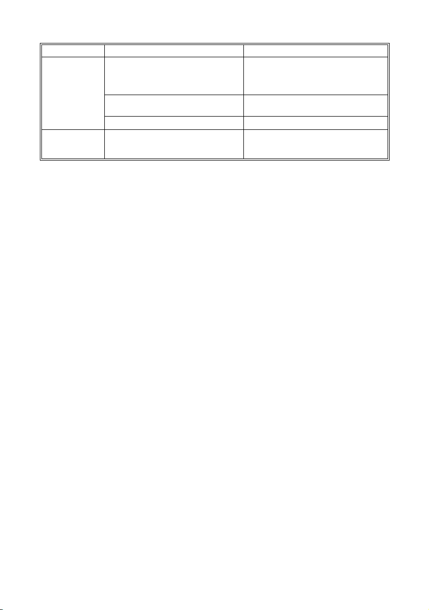
Troubleshooting/Problem Solving SMA Technologie AG
Fault display Cause Fault correction
VBatLow Battery voltage too low:
Watchdog Automatic reset If this fault frequently occurs please
wrong parameter setting
Deeply discharged batteries Recharge the batteries as soon as
One or more defective batteries Check the batteries.
Check the value of the "23-1
VdcBatNominal" parameter setting (see
section 10.3 "Adjustable System
Parameters" (page 51)).
possible.
contact your installer or the SMA hotline
(see section 14 "Contact" (page 65)).
11.2 Troubleshooting FAQs
Here you will find answers to frequently asked questions (FAQs):
1. The Sunny Island 3324/4248 does not switch to the running generator, even
though the generator control relay has closed (Gen_Request) (the "24-1
GenControl" parameter is set to "Direct", see page 30).
- Check the generator fuses.
- The stand-alone grid load current ("11-2 AmpacInverter" parameter) is
greater than the maximum generator current ("24-2 AmpacGenMax"
parameter). Reduce the stand-alone grid load until the stand-alone grid load
current is smaller than the maximum generator current. The Sunny Island
3324/4248 can now switch to the generator.
- The reverse power that can be fed back into the generator for up to five
seconds has been exceeded. A "!" is shown in the display. The generator
cannot be connected for a period of 20 minutes. Set the "24-3 GenOperation"
parameter to "Release" (see page 33).
2. The Sunny Island 3324/4248 does not switch to the running generator, the
generator control relay (Gen_Request) is open .
- The generator was manually started, even though the "24-1 GenControl"
parameter is set to "Direct" (see page 30) or "GenMan" (see page 31).
- Set the "24-3 GenOperation" parameter to "Run1h" (see page 33). The
Sunny Island 3324/4248 switches to the generator for a period of one
hour. After one hour, the generator is automatically switched off by the
Sunny Island 3324/4248 and the "24-3 GenOperation" parameter is set
to the previous state.
- You can also set the "24-3 GenOperation" parameter to "Start" (see
page 32). The Sunny Island 3324/4248 will immediately switch to the
generator. You must note that the Sunny Island 3324/4248 will no longer
switch off the generator. Only when you manually reset the "24-3
GenOperation" parameter back to "Auto" can the Sunny Island 3324/
4248 again assume control of the generator.
Page 58 SI3324/4248-14:FE2406 User Manual
Page 59

SMA Technologie AG Troubleshooting/Problem Solving
- The generator reverse power has been exceeded. A "!" is shown in the
display. Set the "24-3 GenOperation" parameter to "Release" (see page 33),
the Sunny Island 3324/4248 will switch to the generator.
3. The DC circuit breaker on the Sunny Island 3324/4248 is set to "On" but the
display remains dark.
- The inverter has switched off to protect the batteries from deep discharge (see
also section 6.3 "Deep Discharge Protection / Battery State" (page 39)). To
restart the Sunny Island 3324/4248, see section 4.2.4 "Restarting the
Automatic Shutdown" (page 22).
4. The Sunny Island 3324/4248 only briefly switches to the generator and
constantly changes from battery charging mode (Charge mode) to inverter
mode (Invert mode).
- The "24-2 AmpacGenMax" parameter (see section 5.2.2 "Setting the Output
Current Limit" (page 32)) is too high. Set the "24-2 AmpacGenMax"
parameter to a value that is 85 % of the nominal generator current.
- The limits for the maximum permissible AC voltage or the minimum permissible
frequency of the generator are too strict. Increase the limits for voltage and/
or frequency according to the technical data of your generator.
5. The stand-alone grid frequency is not 50 Hz.
- The Sunny Boy inverter is controlled via the frequency (see section 7
"Frequency Shift Power Control (FSPC)" (page 41)).
- The "AFRA" function of the Sunny Island 3324/4248 is activated (see the
Sunny Island 3324/4248 user manual, section "Automatic Frequency
Adjustment").
6. The "VAC-Low" fault (output voltage too low) occurs when the Sunny Island
3324/4248 is started.
- A short-circuit exists in the stand-alone grid. Check the AC output connections
of the stand-alone grid.
- The loads connected to the stand-alone grid are too heavy. The power/
electrical energy of the Sunny Island 3324/4248 is not sufficient to supply the
loads. Switch of some of the loads and restart the Sunny Island 3324/4248.
User Manual SI3324/4248-14:FE2406 Page 59
Page 60

Troubleshooting/Problem Solving SMA Technologie AG
Page 60 SI3324/4248-14:FE2406 User Manual
Page 61

SMA Technologie AG Technical Data
12 Technical Data
SI 3324 SI 4248
Output data:
Nominal AC voltage (V
Nominal frequency (f
Continuous AC output (P
Continuous AC output (P
AC output for 30 min at 25°C 4200 W 5400 W
AC output for 5 min at 25°C 4400 W 6200 W
AC output for 1 min at 25°C 5000 W 7000 W
Nominal AC current (I
Max. current (peak value) for 100 ms 100 A (100 ms) 100 A (100 ms)
Harmonic distortion of output voltage
)
(K
VAC
Phase shift factor cosϕ -1 to +1 -1 to +1
Input data
Input voltage (V
Input frequency (f
AC, ext
) (adjustable) 50 Hz (40 to 60 Hz) 50 Hz (40 to 60 Hz)
ext
Max. AC input current (I
(adjustable)
Max. input power (P
AC, ext
Battery data
Battery voltage (V
Bat, nom
Max. battery charging current (I
Continuous charging current (I
Battery capacity 100 to 6000 Ah 100 to 6000 Ah
Charge control IV
Efficiency/power consumption
Max. efficiency (typical) 94,5 % 95 %
Own consumption (no load/standby) 22 W (< 4 W) 22 W (< 4 W)
German standards
) (adjustable) 230 V (202 to 253 V) 230 V (202 to 253 V)
AC, nom
) 50 Hz 50 Hz
nom
) at 25°C 3300 W 4200 W
nom
) at 45°C 2300 W 3400 W
nom
) 14.5 A 18 A
AC, nom
< 3 % < 3 %
) (adjustable) 230 V (172.5 to 250 V) 230 V (172.5 to 250 V)
AC, ext
)
56 A (2 to 56 A) 56 A (2 to 56 A)
) 12.8 kW 12.8 kW
) (adjustable) 24 VDC (21 to 32 VDC) 48 VDC (41 to 63 VDC)
Bat, max
Bat, nom
) 140 A
) 104 A
V process with
0
automatic full and
DC
DC
100 A
DC
80 A
DC
IV0V process with automatic
full and equalization charge
equalization charge
DIN EN 50178,
DIN EN 61000-3-2 (when
charging),
DIN EN 61000-6-1,
DIN EN 61000-6-2,
DIN EN 61000-6-3,
DIN EN 61000-6-4
DIN EN 50178,
DIN EN 61000-3-2 (when
charging),
DIN EN 61000-6-1,
DIN EN 61000-6-2,
DIN EN 61000-6-3,
DIN EN 61000-6-4
User Manual SI3324/4248-14:FE2406 Page 61
Page 62

Technical Data SMA Technologie AG
SI 3324 SI 4248
Certification
CE CE
Protection degree
Per DIN EN 60529: IP 30 IP 30
USA NEMA1 (indoor) NEMA1 (indoor)
inverter protection
Short-circuit, overload,
overtemperature
Interfaces
2 LEDs
4 buttons
two-line display
1 relay for load shedding
1 relay for controlling a
diesel generator
RS485/RS232 galvanically
isolated (optional)
Mechanical data
Width x height x depth (390 x 590 x 245) mm (390 x 590 x 245) mm
Weight 39 kg (approx.) 39 kg (approx.)
Ambient conditions
Ambient temperature from -25°C to +50°C from -25°C to +50°C
Miscellaneous
Guarantee (EU) 2 years 2 years
Accessories
Ext. battery temperature sensor included included
Generator management (GenMan) optional optional
Short-circuit, overload,
overtemperature
2 LEDs
4 buttons
two-line display
1 relay for load shedding
1 relay for controlling a
diesel generator
RS485/RS232 galvanically
isolated (optional)
Page 62 SI3324/4248-14:FE2406 User Manual
Page 63

SMA Technologie AG CE Declaration of Conformity
13 CE Declaration of Conformity
CE Declaration of Conformity
for off-grid inverters
Product: Sunny Island
Type: SI 3324, SI 4248
We declare that the above specified device is compliant with the regulations of the European
Community, in terms of the design and the version fabricated by SMA. This especially applies
for the EMC Regulation defined in 89/336/EWG and the low voltage regulation defined in
73/23/EWG.
The device is compliant with the following standards:
DIN EN 50178 (04.98) (VDE 0160)
DIN EN 61000-3-2: 2001-12 (in charging operation)
DIN EN 61000-6-1: 2002-08
DIN EN 61000-6-2: 2002-08
DIN EN 61000-6-3: 2002-08
DIN EN 61000-6-4: 2002-08
The above mentioned device is therefore marked with a CE sign.
Note:
This declaration of conformity becomes invalid in case
· the product is modified, complemented or changed,
· and/or components, other than those belonging to the SMA accessories, are installed in the product,
· as well as in case of incorrect connection or inproper usage
without explicit written confirmation by SMA.
Niestetal, 13.03.2006
SMA Technologie AG
i.V. Andreas Berger
(Head of Development)
SMA Technologie AG
Hannoversche Straße 1-5
34266 Niestetal
Tel. +49 561 9522 – 0
Fax +49 561 9522 – 100
www.SMA.de
info@SMA.de
SI33-42-CE-11:BE1106
User Manual SI3324/4248-14:FE2406 Page 63
Page 64

CE Declaration of Conformity SMA Technologie AG
Page 64 SI3324/4248-14:FE2406 User Manual
Page 65

SMA Technologie AG Contact
14 Contact
If you have any questions or queries, please contact us. A team of qualified engineers
and technicians is at your disposal.
Help us to help you by having the following information ready when you call us:
• Type of inverter
• Serial number of the Sunny Island 3324/4248
•Firmware version
• Fault message shown in the display
• Battery size and battery type
• Type and size of additional energy sources (generators, PV systems, PV inverters)
• Communications products used
Address:
SMA Technologie AG
Hannoversche Straße 1 - 5
34266 Niestetal
Germany
Tel. (+49) 561 95 22 - 399
Fax (+49) 561 95 22 - 4697
SunnyIsland.hotline@SMA.de
www.SMA.de
User Manual SI3324/4248-14:FE2406 Page 65
Page 66

Contact SMA Technologie AG
Page 66 SI3324/4248-14:FE2406 User Manual
Page 67

SMA Technologie AG Glossary
21 Glossary
Absorption phase
Constant Voltage phase: A charging phase using constant charging voltage. The
charging current constantly decreases in this phase.
AC
Abbreviation for "Alternating Current"
AC coupling
The AC side connection between loads, generators and storage devices.
AGM battery
Absorbent Glass Mat separator battery. This is a battery where the electrolyte (a
mixture of water and sulfuric acid) is bound to a glass fiber mat. This is a type of a
sealed lead acid battery. A gas mixture (hydrogen and oxygen) is always generated
when lead-acid batteries are charged and in normal operation this internally
recombines to form water. This removes the need for regularly refilling the battery
cells with water, which is why these batteries are often described as "low
maintenance" or even "maintenance free". AGM batteries are available from many
different manufacturers for a wide range of applications. They usually have very
good high current properties but are not very charge-cycle resistant.
Ah
Abbreviation for "Ampere hours". Unit of electrical charge, one ampere hour is the
charge provided by a constant current of 1 A over a period of one hour.
Backup system
Backup systems are power supply systems that provide an extra level of security for
standard power supply systems. The public grid is usually the standard power supply
system and the backup system is provided by an additional stand-alone grid in the
case of a power outage. In addition to the backup systems, diesel generators in PV
battery systems are also described as backup generators. Here they perform the
same task as a backup system for the public grid.
Battery
A battery is an electrochemical storage device that can release previously stored
chemical energy as electrical energy. A distinction is made between nonrechargeable primary elements (often used in consumer markets) and rechargeable
secondary elements (accumulators). In stand-alone grid systems, lead acid batteries
are almost always used and, very rarely, Nickel/Cadmium batteries are used as
secondary rechargeable elements.
Battery bank
See Battery system
User Manual SI3324/4248-14:FE2406 Page 153
Page 68

Glossary SMA Technologie AG
Battery charge mode
An operating mode of a battery inverter in which the inverter takes energy from the
AC grid to charge the batteries in a controlled fashion. In this mode of operation, the
battery inverter is responsible for correctly charging the batteries and acts like an
independent battery charger.
Battery inverter
See Battery power converter
Battery management
The battery management is responsible for the optimum charging of the battery bank
and for protection against deep discharge. This is the only way of ensuring that the
battery service life reflects the manufacturer's specifications.
Battery power converter
A bidirectional power converter that can regulate voltage and frequency in a standalone grid as well as correctly charging the batteries.
Battery system
Serial and possibly also parallel connection of several identical batteries. Battery
banks of 12 V, 24 V, 48 V and 60 V are typical.
Boost charge
Rapid charging: Allows the batteries to be charged to a level of approx. 85 – 90 %
in the shortest time and the most efficient manner.
Bulk phase
I-Phase: The charging phase in which charging can be done using the maximum
allowable charging current.
Capacity
Describes the storage capability of a cell or battery, specified in Ah (ampere hours).
The capacity of a battery is heavily dependent on the charging cycle, the amount of
current drawn and the temperature.
Central inverter
An inverter concept, in which all PV modules are connected to each other (in series
and/or parallel) and which uses a single inverter for feeding energy into the mains
supply grid. The low cost of the inverter is usually offset by the much higher
installation efforts required and possible yield losses due to variations in shadowing
of different solar modules.
Charge level
Describes the current amount of charge that can be drawn from the battery, in
percent of the nominal capacity (100 % = battery full, 0 % = battery empty).
Page 154 SI3324/4248-14:FE2406 User Manual
Page 69

SMA Technologie AG Glossary
Charge mode
See Battery charging mode
C-rate
The nominal capacity specification is always provided with the discharge time on
which the capacity is based. The nominal capacity is the product of the constant
charging current IN and the discharge time tN, that passes between commencement
of discharging the fully charged battery until the final discharge voltage V
reached. In permanently on-site batteries, the C10 capacity is usually specified. i.e.
a battery with C10 = 200 Ah can be discharged for 10 hours at a nominal current of
0.1 × C
= I10 = 20 A.
10
is
S
DC
Abbreviation for "Direct Current"
Derating
A controlled reduction in performance, usually dependent on component
temperatures. Derating is used instead of performing a complete shutdown of the
system.
DSP
Abbreviation for Digital Signal Processor. A DSP is a microprocessor chip especially
developed for digital signal processing and control.
Electrolyte
Allows the conduction of ions within a battery. In lead acid batteries, the electrolyte
is diluted sulfuric acid and is also a reactant in the electrochemical reaction. Nickel/
Cadmium batteries use an alkaline electrolyte (potassium hydroxide).
EPROM
See Flash EEPROM
Equalize charge
Equalize charge: Allows multiple series-connected battery cells to be charged to a
unified charge level of 95 – 100 %. Without regular equalization charging, the
charge states of the various cells slowly drift apart, which can lead to premature
battery bank failure.
Firmware
Firmware is software that is stored in a chip in various electronic devices, such as
Sunny Island, hard disk recorders, DVD burners and players, newer television sets,
household appliances and computers - in contrast to software that is stored on a hard
drive, CD-ROM or other media. These days, firmware is usually stored in Flash
memory or an EEPROM.
User Manual SI3324/4248-14:FE2406 Page 155
Page 70

Glossary SMA Technologie AG
FLA
Flooded Lead Acid battery: A lead acid battery with liquid electrolyte, also often
described as a sealed lead acid battery.
Flash EEPROM
The abbreviation EEPROM stands for Electrically Erasable Programmable Read-Only
Memory. Flash memory is a digital storage chip, the exact designation is Flash
EEPROM. In contrast to "normal" EEPROM storage, individual bytes (the smallest
addressable storage units) cannot be deleted.
EEPROM is a non-volatile, electronic storage component that is used in the Sunny
Island, the computer industry (among others) and usually in Embedded Systems.
Flash EEPROMs are used where information must be permanently stored in the
smallest amount of space, e.g. for storing the firmware.
Float charge
Maintenance charge: Allows the batteries to be slowly charged to a charge level of
100 % without the negative effects of overcharging. Complete charging to 100 %
using float charge takes several days. For this reason, float charging is more
important for grid backup systems and less important for stand-alone grids.
Full charge
Recharging of the batteries to a level of approx. 95 % on a regular basis (at least
once a month). This efficiently avoids premature aging of the batteries caused by
inadequate charging.
Gel battery
A type of battery in which the electrolyte (a mixture of water and sulfuric acid) is
bound into a gel. This is a type of sealed lead acid battery. A gas mixture (hydrogen
and oxygen) is always generated when lead acid batteries are charged, and in
normal operation this internally recombines to form water. This removes the need for
regularly refilling the battery cells with water, which is why these batteries are often
described as "low maintenance" or even "maintenance free" (see also AGM
batteries). Gel batteries are available from many different manufacturers for a wide
range of applications. There are Gel batteries for high-current applications but also
for cycle operation with very high cycle resistance.
Grid-coupled system
PV system that is connected to the power supply grid of an external energy supplier.
Independent disconnection device
The "Independent disconnection device between a grid parallel power generating
system and the public low voltage grid" (DIN VDE 0126-1-1) is an equivalent
replacement for a normal public disconnection device with isolation function that is
accessible to the distribution grid operator at any time. This is a mandatory safety
Page 156 SI3324/4248-14:FE2406 User Manual
Page 71

SMA Technologie AG Glossary
device that prevents power from a solar power system being fed into an external
power grid when the external power generator is not functioning. In the Sunny Boy/
Sunny Mini Central, this function is assumed by the "SMA grid guard Version 2".
Inverters
A device for converting the direct current (DC) from the PV generator into alternating
current (AC), which is used by most normal household devices and especially for
feeding energy into an existing supply grid. Inverters for PV systems usually include
one or more MPP trackers, store operating data and monitor the grid connections of
the PV system (see also MSD).
Inverter mode
See Inverter operation
Inverter operation
Operating mode of a battery inverter where it supplies the stand-alone grid from the
battery energy. In this operating mode, the battery inverter is especially responsible
for the control of frequency and voltage in the stand-alone grid.
Maximum Power Point "MPP"
The working point (current/voltage characteristic curve) of a PV generator where the
maximum power can be drawn. The actual MMP changes constantly depending
(e.g.) on the level of solar irradiation and the ambient temperature.
MPP tracker
Regulation of the power drawn so that a PV generator remains as close as possible
to the MPP. This working point varies with the solar irradiation and the temperature
conditions of the modules. MPP tracking optimizes the extraction of electrical power
and is a feature of inverters and charge controllers.
MSD
See Independent disconnection device
Multi-string inverter
An inverter that combines the advantages of several string inverters (separate MPP
tracking of individual strings) and a central inverter (lower performance specific
costs).
NiCd
Nickel/Cadmium battery, contains Nickel, Cadmium, and potassium hydroxide as
the electrolyte. They require a significantly higher charging voltage, have a lower
level of efficiency and are significantly more expensive than lead acid batteries. Their
robustness, cycle resistance and low-temperature capabilities allow them to be used
in certain special applications.
User Manual SI3324/4248-14:FE2406 Page 157
Page 72

Glossary SMA Technologie AG
Overload capability
The overload capability of an inverter describes the ability of the inverter to supply
short-term (seconds or minutes) excessive loads, that can be significantly higher than
the nominal capacity in battery inverters. The overload capability is important to
allow electrical machines with a nominal power output close to the nominal power
output of the stand-alone grid inverter to be started, since these machines typically
require six times the nominal current when starting.
Parallel connection
Parallel connection of the batteries (all positive poles together and all negative poles
together) increases the capacity of the battery bank while keeping the voltage
constant. Example: Two 24 V/100 Ah batteries connected in parallel still have a
voltage of 24 V, but have a capacity of 100 Ah + 100 Ah = 200 Ah.
Piggy-Back (Board)
A printed circuit board that is plugged into another board to increase performance
or expand capabilities. A piggy-back board can also replace a single chip. In this
case, the chip is removed and the board is plugged into the empty socket.
PLC
Abbreviation for Power Line Communication: Describes the process of data transfer
over the grid supply cables. The PLC power module is used to amplify the signal and
is connected in Multi-String and Sunny Mini Central inverters. Powerline
communication is not suitable for Sunny Island inverters.
PV
Photovoltaics (PV) is the conversion of solar irradiation into electrical energy using
special semiconductors called solar cells.
PV array
See PV generator.
PV generator
Technical device for the conversion of light energy into electrical energy. All the
series and parallel mounted and electrically connected solar modules in a PV system
are known as the PV generator.
PV module
See Solar module.
PV array
See PV generator.
Page 158 SI3324/4248-14:FE2406 User Manual
Page 73

SMA Technologie AG Glossary
PV system
Describes a solar power system for generating electrical power. Describes the
complete collection of components needed for the acquisition and utilization of solar
energy. As well as the PV generator, this includes the Sunny Boy or Sunny Mini
Central, for example, in the case of grid-coupled systems.
Self discharge
Loss of battery charge while it is stored or not used. A higher ambient temperature
has a strong influence on self discharge.
Series connection
In this case the positive pole of each battery is connected to the negative pole of the
next battery. There is only one circuit where current can flow. Series connection
increases the voltage of the entire battery bank. If four 12 V batteries with a capacity
of 100 Ah each are connected in series, the total voltage is 4 × 12 V = 48 V, while
the total capacity remains at 100 Ah.
SOC
State of Charge: The charge level of the batteries, see Charge level. If (e.g) 25 Ah
is taken from a 100-Ah battery, the charge level (SOC) is then 75 %.
Solar energy
"Sun energy", this means energy from sunlight or other solar irradiation (heat and/
or UV radiation).
Solar module
Electrical connection of several solar cells encapsulated in a housing to protect the
sensitive cells from mechanical stress and environmental effects.
Solar cell
An electronic component that generates electrical energy when irradiated with
sunlight. Since the voltage produced by a solar cell is very small (approx. 0.5 V),
several solar cells are combined to form a solar module. The most common
semiconductor material presently used for solar cells is silicon, which is manufactured
in different forms (monocrystalline, polycrystalline, amorphous). In addition to
different mechanical variations, that are usually designed to increase the level of
efficiency, completely new materials are currently being tested (Cadmium Telluride,
Cadmium Indium Sulphide, Titanium Dioxide and many others.)
Stand-alone grid system
An energy generation system that is completely independent of any external power
sources.
User Manual SI3324/4248-14:FE2406 Page 159
Page 74

Glossary SMA Technologie AG
String
Describes a group of solar modules connected in series. A PV system usually consists
of a number of strings, which avoids yield losses due to variations in shading over
different modules.
String inverter
An inverter concept that avoids the disadvantages of the central inverter concept. The
PV is split into individual strings, each of which is connected to the external mains
supply with its own string inverter. This greatly simplifies installation and greatly
reduces the yield losses caused by manufacturing deviations or variations in
shadowing of the solar modules.
VRLA
Valve Regulated Lead Acid battery: Lead-acid battery with semi-solid electrolyte or
sealed lead acid battery. Examples of this type of battery are Gel batteries and AGM
batteries (Absorbent Glass Mat).
Page 160 SI3324/4248-14:FE2406 User Manual
Page 75

SMA Technologie AG
User Manual SI3324/4248-14:FE2406 Seite 75
Page 76

The information contained in this document is the property of SMA Technologie AG. Publishing its content,
either partially or in full, requires the written permision of SMA Technologie AG. Any internal company copying
of the document for the purposes of evaluating the product or its correct implementation is allowed and does
not require permission.
Exclusion of liability
The general terms and conditions of delivery of SMA Technologie AG shall apply.
The content of these documents is continually checked and amended, where necessary. However,
discrepancies cannot be excluded. No guarantee is made for the completeness of these documents. The latest
version is available on the Internet at www.SMA.de or from the usual sales channels.
Guarantee or liability claims for damages of any kind are exlcuded if they are caused by one or more of the
following:
• Improper or inappropriate use of the product
• Operating the product in an unintended environment
• Operating the product whilst ignoring relevant, statutory safety regulations in the deployment location
• Ignoring safety warnings and instructions contained in all documents relevant to the product
• Operating the product under incorrect safety or protection conditions
• Altering the product or supplied software without authority
• The product malfunctions due to operating attached or neighboring devices beyond statutory limit values
• In case of unforeseen calamity or force majeure
Software licensing
The use of supplied software produced by SMA Technologie AG is subject to the following conditions:
This software may be copied for internal company purposes and may be installed on any number of
computers. Supplied source codes may be changed or adapted for internal company purposes on your own
responsibility. Drivers may also be transferred to other operating systems. Source codes may only be published
with the written permission of SMA Technologie AG. Sub-licensing of software is not permissible.
Limitation of liability: SMA Technologie AG rejects any liability for direct or indirect damages arising from the
use of software developed by SMA Technologie AG. This also applies to the provision or non-provision of
support activities.
Supplied software not developed by SMA Technologie AG is subject to the respective licensing and liability
agreements of the manufacturer.
Trademarks
All trademarks are recognized even if these are not marked separately. Missing designations do not mean that
a product or brand is not a registered trademark.
SMA Technologie AG
Hannoversche Straße 1-5
34266 Niestetal
Germany
Tel. +49 561 9522-0
Fax +49 561 9522-100
www.SMA.de
E-mail: info@SMA.de
© 2005 SMA Technologie AG. All rights reserved.
Page 77

Page 78

Page 79

Page 80

www.SMA.de
Sales
Solar Technology
SMA Technologie AG
Hannoversche Strasse 1–5
34266 Niestetal, Germany
Tel. : +49 561 9522 4000
Fax: +49 561 9522 4040
E-Mail: Info@SMA.de
Freecall: +800 SUNNYBOY
Freecall: +800 78669269
Innovation in Systems Technology
for the Success of Photovoltaics
SMA Technologie AG
Seite 80 SI3324/4248-14:FE2406 User Manual
 Loading...