

Page 1
Installation - Quick Reference Guide
SMA FLEXIBLE STORAGE SYSTEM with Battery Backup Function
Battery backup systems including increased self-consumption with
SUNNY ISLAND 3.0M / 4.4M / 6.0H / 8.0H and SUNNY HOME MANAGER
Ersatzstrom-IS-en-30 | Version 3.0 ENGLISH
Page 2

Legal Provisions SMA Solar Technology AG
Legal Provisions
The information contained in this document is the property of SMA Solar Technology AG. Publishing its content, either
partially or in full, requires the written permission of SMA Solar Technology AG. Any internal company copying of the
document for the purposes of evaluating the product or its correct implementation is allowed and does not require
permission.
SMA Warranty
You can download the current warranty conditions from the Internet at www.SMA-Solar.com.
Trademarks
All trademarks are recognized, even if not explicitly identified as such. A lack of identification does not mean that a
product or symbol is not trademarked.
The BLUETOOTH
marks by SMA Solar Technology AG is under license.
®
Modbus
is a registered trademark of Schneider Electric and is licensed by the Modbus Organization, Inc.
QR Code is a registered trademark of DENSO WAVE INCORPORATED.
®
Phillips
Torx
and Pozidriv® are registered trademarks of Phillips Screw Company.
®
is a registered trademark of Acument Global Technologies, Inc.
®
word mark and logos are registered trademarks owned by Bluetooth SIG, Inc. and any use of these
SMA Solar Technology AG
Sonnenallee 1
34266 Niestetal
Germany
Tel. +49 561 9522-0
Fax +49 561 9522-100
www.SMA.de
E-mail: info@SMA.de
© 2004 to 2014 SMA Solar Technology AG. All rights reserved.
2 Ersatzstrom-IS-en-30 Installation - Quick Reference Guide
Page 3

SMA Solar Technology AG Table of Contents
Table of Contents
1 Information on this Document. . . . . . . . . . . . . . . . . . . . . . . . . . . . . . . . . . . . . . . . . . . . . . . . . . . . . 5
1.1 Validity . . . . . . . . . . . . . . . . . . . . . . . . . . . . . . . . . . . . . . . . . . . . . . . . . . . . . . . . . . . . . . . . . . . . . . . . . . . . . . 5
1.2 Content and Structure of This Document. . . . . . . . . . . . . . . . . . . . . . . . . . . . . . . . . . . . . . . . . . . . . . . . . . . . . 5
1.3 Target Group . . . . . . . . . . . . . . . . . . . . . . . . . . . . . . . . . . . . . . . . . . . . . . . . . . . . . . . . . . . . . . . . . . . . . . . . . 5
1.4 Additional Information . . . . . . . . . . . . . . . . . . . . . . . . . . . . . . . . . . . . . . . . . . . . . . . . . . . . . . . . . . . . . . . . . . 5
1.5 Symbols for Information . . . . . . . . . . . . . . . . . . . . . . . . . . . . . . . . . . . . . . . . . . . . . . . . . . . . . . . . . . . . . . . . . 5
1.6 Typographies . . . . . . . . . . . . . . . . . . . . . . . . . . . . . . . . . . . . . . . . . . . . . . . . . . . . . . . . . . . . . . . . . . . . . . . . . 6
1.7 Nomenclature. . . . . . . . . . . . . . . . . . . . . . . . . . . . . . . . . . . . . . . . . . . . . . . . . . . . . . . . . . . . . . . . . . . . . . . . . 6
2 Safety . . . . . . . . . . . . . . . . . . . . . . . . . . . . . . . . . . . . . . . . . . . . . . . . . . . . . . . . . . . . . . . . . . . . . . . . 7
2.1 Intended Use . . . . . . . . . . . . . . . . . . . . . . . . . . . . . . . . . . . . . . . . . . . . . . . . . . . . . . . . . . . . . . . . . . . . . . . . . 7
2.2 Safety Precautions . . . . . . . . . . . . . . . . . . . . . . . . . . . . . . . . . . . . . . . . . . . . . . . . . . . . . . . . . . . . . . . . . . . . . 9
3 Information and System Description . . . . . . . . . . . . . . . . . . . . . . . . . . . . . . . . . . . . . . . . . . . . . . 12
3.1 Requirements of the "VDE Forum Network Technology / Network Operations (FNN)" . . . . . . . . . . . . . . . 12
3.2 System Information . . . . . . . . . . . . . . . . . . . . . . . . . . . . . . . . . . . . . . . . . . . . . . . . . . . . . . . . . . . . . . . . . . . . 12
3.3 Design and Functions of the Battery Backup System . . . . . . . . . . . . . . . . . . . . . . . . . . . . . . . . . . . . . . . . . . 14
3.4 Design and Functions of the Automatic Transfer Switch . . . . . . . . . . . . . . . . . . . . . . . . . . . . . . . . . . . . . . . . 16
3.4.1 Devices of the Automatic Transfer Switch . . . . . . . . . . . . . . . . . . . . . . . . . . . . . . . . . . . . . . . . . . . . . . . . . . . . .16
3.4.2 Grid Disconnection . . . . . . . . . . . . . . . . . . . . . . . . . . . . . . . . . . . . . . . . . . . . . . . . . . . . . . . . . . . . . . . . . . . . . .17
3.4.3 Grounding Device for the Battery Backup Grid. . . . . . . . . . . . . . . . . . . . . . . . . . . . . . . . . . . . . . . . . . . . . . . . .18
3.4.4 Phase Coupling for Single-Phase Battery Backup Systems . . . . . . . . . . . . . . . . . . . . . . . . . . . . . . . . . . . . . . . .19
4 Battery Backup Systems With All-Pole Disconnection. . . . . . . . . . . . . . . . . . . . . . . . . . . . . . . . . 20
4.1 Single-Phase Battery Backup System . . . . . . . . . . . . . . . . . . . . . . . . . . . . . . . . . . . . . . . . . . . . . . . . . . . . . . 20
4.1.1 Schematic Diagram of the Automatic Transfer Switch . . . . . . . . . . . . . . . . . . . . . . . . . . . . . . . . . . . . . . . . . . . .20
4.1.2 Circuitry Overview. . . . . . . . . . . . . . . . . . . . . . . . . . . . . . . . . . . . . . . . . . . . . . . . . . . . . . . . . . . . . . . . . . . . . . .21
4.1.3 Connecting the Sunny Island Inverter . . . . . . . . . . . . . . . . . . . . . . . . . . . . . . . . . . . . . . . . . . . . . . . . . . . . . . . .22
4.2 Three-Phase Battery Backup System . . . . . . . . . . . . . . . . . . . . . . . . . . . . . . . . . . . . . . . . . . . . . . . . . . . . . . . 24
4.2.1 Schematic Diagram of the Automatic Transfer Switch . . . . . . . . . . . . . . . . . . . . . . . . . . . . . . . . . . . . . . . . . . . .24
4.2.2 Circuitry Overview. . . . . . . . . . . . . . . . . . . . . . . . . . . . . . . . . . . . . . . . . . . . . . . . . . . . . . . . . . . . . . . . . . . . . . .25
4.2.3 Connecting the Master . . . . . . . . . . . . . . . . . . . . . . . . . . . . . . . . . . . . . . . . . . . . . . . . . . . . . . . . . . . . . . . . . . .26
4.2.4 Connecting the Slaves . . . . . . . . . . . . . . . . . . . . . . . . . . . . . . . . . . . . . . . . . . . . . . . . . . . . . . . . . . . . . . . . . . . .28
5 Battery Backup Systems Without All-Pole Disconnection . . . . . . . . . . . . . . . . . . . . . . . . . . . . . . 30
5.1 Single-Phase Battery Backup System . . . . . . . . . . . . . . . . . . . . . . . . . . . . . . . . . . . . . . . . . . . . . . . . . . . . . . 30
5.1.1 Schematic Diagram of the Automatic Transfer Switch . . . . . . . . . . . . . . . . . . . . . . . . . . . . . . . . . . . . . . . . . . . .30
5.1.2 Circuitry Overview. . . . . . . . . . . . . . . . . . . . . . . . . . . . . . . . . . . . . . . . . . . . . . . . . . . . . . . . . . . . . . . . . . . . . . .31
5.1.3 Connecting the Sunny Island Inverter . . . . . . . . . . . . . . . . . . . . . . . . . . . . . . . . . . . . . . . . . . . . . . . . . . . . . . . .32
5.2 Three-Phase Battery Backup System . . . . . . . . . . . . . . . . . . . . . . . . . . . . . . . . . . . . . . . . . . . . . . . . . . . . . . . 34
5.2.1 Schematic Diagram of the Automatic Transfer Switch . . . . . . . . . . . . . . . . . . . . . . . . . . . . . . . . . . . . . . . . . . . .34
5.2.2 Circuitry Overview. . . . . . . . . . . . . . . . . . . . . . . . . . . . . . . . . . . . . . . . . . . . . . . . . . . . . . . . . . . . . . . . . . . . . . .35
5.2.3 Connecting the Master . . . . . . . . . . . . . . . . . . . . . . . . . . . . . . . . . . . . . . . . . . . . . . . . . . . . . . . . . . . . . . . . . . .36
5.2.4 Connecting the Slaves . . . . . . . . . . . . . . . . . . . . . . . . . . . . . . . . . . . . . . . . . . . . . . . . . . . . . . . . . . . . . . . . . . . .38
6 Connecting the Sunny Home Manager . . . . . . . . . . . . . . . . . . . . . . . . . . . . . . . . . . . . . . . . . . . . 39
Installation - Quick Reference Guide Ersatzstrom-IS-en-30 3
Page 4

Table of Contents SMA Solar Technology AG
7 Commissioning . . . . . . . . . . . . . . . . . . . . . . . . . . . . . . . . . . . . . . . . . . . . . . . . . . . . . . . . . . . . . . . .40
7.1 Basic Configuration of the Sunny Island Inverter . . . . . . . . . . . . . . . . . . . . . . . . . . . . . . . . . . . . . . . . . . . . . 40
7.2 Testing the Automatic Transfer Switch Function . . . . . . . . . . . . . . . . . . . . . . . . . . . . . . . . . . . . . . . . . . . . . . 44
7.3 Adjusting the Configuration of the Sunny Island Inverter . . . . . . . . . . . . . . . . . . . . . . . . . . . . . . . . . . . . . . . 46
7.3.1 Countries in Which the Configuration Must Be Adjusted. . . . . . . . . . . . . . . . . . . . . . . . . . . . . . . . . . . . . . . . . .46
7.3.2 Adjusting the Configuration for Denmark . . . . . . . . . . . . . . . . . . . . . . . . . . . . . . . . . . . . . . . . . . . . . . . . . . . . .47
7.3.3 Adjusting the Configuration for France . . . . . . . . . . . . . . . . . . . . . . . . . . . . . . . . . . . . . . . . . . . . . . . . . . . . . . .47
7.3.4 Adjusting the Configuration for Austria . . . . . . . . . . . . . . . . . . . . . . . . . . . . . . . . . . . . . . . . . . . . . . . . . . . . . . .47
7.3.5 Adjusting the Configuration for Switzerland . . . . . . . . . . . . . . . . . . . . . . . . . . . . . . . . . . . . . . . . . . . . . . . . . . .48
7.4 Adjusting the Configuration of the PV Inverters . . . . . . . . . . . . . . . . . . . . . . . . . . . . . . . . . . . . . . . . . . . . . . 48
7.5 Attaching the Labels. . . . . . . . . . . . . . . . . . . . . . . . . . . . . . . . . . . . . . . . . . . . . . . . . . . . . . . . . . . . . . . . . . . 49
7.6 Activating Phase Coupling in Single-Phase Battery Backup Systems . . . . . . . . . . . . . . . . . . . . . . . . . . . . . . 50
7.7 Commissioning System With Increased Self-Consumption. . . . . . . . . . . . . . . . . . . . . . . . . . . . . . . . . . . . . . 50
7.7.1 Preparing BLUETOOTH Communication. . . . . . . . . . . . . . . . . . . . . . . . . . . . . . . . . . . . . . . . . . . . . . . . . . . . . .50
7.7.2 Commissioning a System With Increased Self-Consumption . . . . . . . . . . . . . . . . . . . . . . . . . . . . . . . . . . . . . . .51
7.8 Commissioning a System Without Increased Self-Consumption. . . . . . . . . . . . . . . . . . . . . . . . . . . . . . . . . . 52
8 Contact. . . . . . . . . . . . . . . . . . . . . . . . . . . . . . . . . . . . . . . . . . . . . . . . . . . . . . . . . . . . . . . . . . . . . . .53
4 Ersatzstrom-IS-en-30 Installation - Quick Reference Guide
Page 5

SMA Solar Technology AG 1 Information on this Document
'$1*(5
:$5 1,1*
&$87,21
/05*$&
1 Information on this Document
1.1 Validity
This document is valid for the SMA Flexible Storage System with battery backup function with the following
SMA products:
• HM-BT-10.GR2 (Sunny Home Manager) from firmware version 1.04
• SI3.0M-11 (Sunny Island 3.0M) from firmware version 3.2
• SI4.4M-11 (Sunny Island 4.4M) from firmware version 3.2
• SI6.0H-11 (Sunny Island 6.0H) from firmware version 3.1
• SI8.0H-11 (Sunny Island 8.0H) from firmware version 3.1
1.2 Content and Structure of This Document
This document summarizes the specific information for the SMA Flexible Storage System with battery backup function
(b attery backup system). Circuitry overviews provide you with a basis for setting up a battery backup system. The structure
of the document specifies the chronological sequence for configuration and commissioning. This document does not
replace the documentation of the individual products. You will find details and help in the event of difficulties in the
documentation of the respective product.
1.3 Target Group
The tasks described in this document must only be performed by qualified persons. Qualified persons must have the
following skills:
• Training in how to deal with the dangers and risks associated with installing and using electrical devices and batteries
• Training in the installation and commissioning of electrical devices
• Knowledge of and adherence to the local standards and directives
• Knowledge of and compliance with this document and all safety precautions
1.4 Additional Information
Links to additional information can be found at www.SMA-Solar.com:
Document title Document type
SMA Flexible Storage System with Battery Backup Function Planning guidelines
1.5 Symbols for Information
Symbol Explanation
Indicates a hazardous situation which, if not avoided, will result in death or serious injury
Indicates a hazardous situation which, if not avoided, can result in death or serious injury
☐ Indicates a requirement for meeting a specific goal
☑ Desired result
✖ A problem that might occur
Installation - Quick Reference Guide Ersatzstrom-IS-en-30 5
Indicates a hazardous situation which, if not avoided, can result in minor or moderate injury
Indicates a situation which, if not avoided, can result in property damage
Information that is important for a specific topic or goal, but is not safety-relevant
Page 6

1 Information on this Document SMA Solar Technology AG
1.6 Typographies
Typography Use Example
bold • Display messages
• Parameters
• Connections
•Slots
• Elements to be selected
• Elements to be entered
> • Several elements that are to be selected • Select 600# Direct Access > Select
[Button/Key] • Button/key on the inverter to be selected
or pressed
• Connect the grounding conductor to
AC 2Gen/Grid.
• Select the parameter 235.01
GnAutoEna and set to Off.
Number.
•Press [ENTER].
1.7 Nomenclature
Complete designation Designation in this document
SMA Flexible Storage System with battery backup
function
Sunny Boy, Sunny Mini Central, Sunny Tripower PV inverter
Grid failure or deviation from the country-specific limiting
values for voltage and frequency
Battery backup system
Grid failure
The term parameter includes parameters with configurable values as well as parameters for displaying values.
6 Ersatzstrom-IS-en-30 Installation - Quick Reference Guide
Page 7

SMA Solar Technology AG 2 Safety
2 Safety
2.1 Intended Use
In the event of grid failure, a battery backup system with Sunny Island supplies loads with energy and a grid-tie PV system
with voltage. In the event of grid failure, an automatic transfer switch disconnects the battery backup grid from the utility
grid. After disconnection, the loads and the PV system have no supply for approximately five seconds, until the battery
backup system can provide active and reactive power once more. The battery backup system supplies the loads and the
PV system can synchronize with the battery backup grid and feed in.
The battery backup system should only be used in countries for which it is licensed or for which it is released by
SMA Solar Technology AG and the grid operator. To fulfill the technical connection requirements of the grid operator
and the local standards and directives, you must select one of the following basic structures:
• Battery backup system with all-pole disconnection
In the event of grid failure, a tie switch disconnects all line conductors and the neutral conductor from the utility grid.
The tie switch is designed with built-in redundancy. If the technical connection requirements of the grid operator or
the local standards and directives call for or allow all-pole disconnection, you must install this basic structure. You
must install all-pole disconnection in the following countries:
–Belgium
–Denmark
–Germany
–France
–Austria
–Switzerland
• Battery backup system without all-pole disconnection
In the event of grid failure, a tie switch disconnects all line conductors from the utility grid. The neutral conductor of
the battery backup grid remains permanently connected to the utility grid. If the technical connection requirements
of the grid operator or the local standards and directives prohibit disconnection of the neutral conductor, you must
install this basic structure. In Australia, you must install a battery backup system without all-pole disconnection.
Each basic structure can be designed either as a three-phase battery backup grid or as a single-phase battery backup
grid. Single-phase battery backup grids can be connected to three-phase utility grids.
In a three-phase battery backup system, in the event of grid failure, three Sunny Island inverters supply all line conductors
with the corresponding line conductor. The three Sunny Island inverters are c onnected in parallel on the DC side and form
one cluster. Only Sunny Island inverters of the same device type may be installed in a cluster. In a three-phase battery
backup system, both single-phase and three-phase PV inverters can be connected. Multiple clusters must not be connected
together.
In a single-phase battery backup system, in the event of grid failure, one Sunny Island supplies the battery backup grid.
A grid failure is only recognized at the line conductor which is connected to the Sunny Island. In the event of grid failure,
only single-phase PV inverters can feed in to a single-phase battery backup grid. A phase coupling, in the event of grid
failure, enables combination of the line conductors to a single-phase distribution grid. With phase coupling, all the loads
in the battery backup grid must be single-phase. No more than one Sunny Island may be connected in a single-phase
battery backup system.
A PV system can be connected in the battery backup grid. The PV system must be suitable for use in battery backup
systems (see the Planning Guidelines "SMA Flexible Storage System with Battery Backup Function" at
www.SMA-Solar.com). The power of the PV system must be appropriate for the system (see Section3.2 "System
Information", page12).
The automatic transfer switch is not a distribution board for the loads or the PV system. The loads and the PV system must
be secured with protective devices in accordance with the local standards and directives. Grid-forming voltage sources
(e.g., generators) must not be connected.
Installation - Quick Reference Guide Ersatzstrom-IS-en-30 7
Page 8

2 Safety SMA Solar Technology AG
The utility grid connected to the automatic transfer switch must be a TN or TT system. The battery backup system is not
suitable for supplying life-sustaining medical devices.
In battery backup systems, the Sunny Island uses lead-acid batteries or lithium-ion batteries for energy storage. Ensure
that the battery room is sufficiently ventilated when using lead-acid batteries (see battery manufacturer's documentation).
If lithium-ion batteries are connected, the battery management of the lithium-ion battery must be compatible with the
Sunny Island (see the Planning Guidelines "SMA Flexible Storage System with Battery Backup Function" at
www.SMA-Solar.com). The lithium-ion battery must be able to supply enough current at maximum output power of the
Sunny Island inverter (for technical data, see the Sunny Island inverter installation manual).
In single-phase battery backup systems, the multifunction relays of the Sunny Island inverter cannot be configured.
In three-phase battery backup systems, the slaves can control devices in the system (e.g., load-shedding contactors),
each via two multifunction relays. The multifunction relays of the master cannot be configured.
The automatic transfer switch must be wired and connected in accordance with this documentation. The equipment or
devices of the automatic transfer switch must satisfy protection class II and be operable without prior knowledge of
electrical technology.
In battery backup systems, the following products must not be connected:
• Sunny Island Charger or other DC charge controllers
• DC loads
The battery backup system records the grid feed-in and purchased electricity with an SMA Energy Meter only.
An SMA Energy Meter does not replace the energy meter of the electric utility company. The grid feed-in and the
purchased electricity are transmitted to one Sunny Island via Speedwire. Therefore, the Sunny Island must be fitted with
the Speedwire data module Sunny Island.
The Sunny Home Manager must not be installed in PV systems in which a Sunny WebBox is installed.
The individual products in the battery backup system must be used for their intended purpose (see documentation of each
product). Any use of the system other than that described in the Intended Use section does not qualify as appropriate.
The enclosed documentation is an integral part of the products. Keep the documentation in a convenient place for future
reference and observe all instructions contained therein.
8 Ersatzstrom-IS-en-30 Installation - Quick Reference Guide
Page 9

SMA Solar Technology AG 2 Safety
:$5 1,1*
2.2 Safety Precautions
This section contains safety precautions that must be observed at all times when working on or with the system. To prevent
personal injury or property damage and to ensure long-term operation of the system, read this section carefully and follow
all safety precautions at all times.
Danger to life from electric shock due to circuit breakers that cannot be tripped
In the battery backup grid, only the circuit breakers that can be tripped by the Sunny Island can be tripped in the event
of a grid failure. Circuit breakers with a higher operating current cannot be tripped. Under fault conditions, there may
be a voltage that poses a danger to life present on accessible parts for several seconds. This can result in fatal or serious
injury.
• Check whether a circuit breaker has a higher trip characteristic than the following circuit breakers which can be
tripped:
– SI3.0M-11 and SI4.4M-11: circuit breaker with trip characteristic B6 (B6A)
– SI6.0H-11 and SI8.0H-11: circuit breaker with trip characteristic B16 (B16A) or circuit breaker with trip
characteristic C6 (C6A)
If a circuit breaker has a higher trip characteristic than the specified circuit breaker which can be tripped, you
should also install a residual-current device of type A.
Danger to life from electric shock due to live voltage
High voltages are present in the battery backup system. When covers are removed (e.g., an enclosure lid), live
components can be touched. Touching can result in death or serious injury due to electric shock.
• When carrying out any work on the electrical installation, wear suitable personal protective equipment.
• Turn off or disconnect the following devices from voltage sources in the given order:
–Sunny Island
– At the grid-connection point, the circuit breaker of the battery backup system
– In the automatic transfer switch, all circuit breakers
– Load-break switch of the battery
• Ensure that the battery backup system cannot be reconnected.
• Open the enclosure lid on the Sunny Island inverter and ensure that no voltage is present.
• Ground and short-circuit the AC conductors outside the automatic transfer switch.
• Cover or isolate any adjacent live components.
Danger to life from electric shock due to damaged devices
Operating a damaged device can lead to hazardous situations that can result in death or serious injuries due to electric
shock.
• Only use the battery backup system when it is technically faultless and in an operationally safe state.
• Ensure that all safety equipment is freely accessible at all times.
• Make sure that all safety equipment is in good working order.
Installation - Quick Reference Guide Ersatzstrom-IS-en-30 9
Page 10
2 Safety SMA Solar Technology AG
:$5 1,1*
&$87,21
Danger to life due to incompatible lithium-ion battery
An incompatible lithium-ion battery can lead to a fire or an explosion. With incompatible lithium-ion batteries, it is not
ensured that the battery management is intrinsically safe and will protect the battery.
• Ensure that the battery complies with the locally applicable standards and directives and is intrinsically safe.
• Ensure that the lithium-ion batteries are approved for use with the Sunny Island.
The list of lithium-ion batteries approved for the Sunny Island is updated constantly (see Technical Information "List
of Approved Lithium-Ion Batteries" at www.SMA-Solar.com).
• If no lithium-ion batteries approved for Sunny Island inverters can be used, you should use lead-acid batteries.
Danger to life due to explosive gases
Explosive gases may escape from the battery and cause an explosion. This can result in fatal or serious injury.
• Protect the battery environment from open flames, embers, or sparks.
• Install, operate, and maintain the battery in accordance with the manufacturer's specifications.
• Do not heat the battery above the temperature permitted or burn the battery.
• Ensure that the battery room is sufficiently ventilated.
Chemical burns and poisoning due to battery electrolyte
If handled inappropriately, battery electrolyte can cause irritation to the eyes, respiratory system, and skin, and it can
be toxic. This may result in blindness and serious chemical burns.
• Protect the battery enclosure against destruction.
• Do not open or deform the battery.
• Whenever working on the battery, wear suitable personal protective equipment such as rubber gloves, apron,
rubber boots, and goggles.
• Rinse acid splashes thoroughly with clear water and consult a doctor.
• Install, operate, maintain, and dispose of the battery according to the manufacturer's specifications.
Risk of injury due to short-circuit currents
Short-circuit currents in the battery can cause heat build-up and electric arcs. Burns or eye injuries due to flashes may
result.
• Remove watches, rings, and other metal objects.
• Use insulated tools.
• Do not place tools or metal parts on the battery.
Risk of burns due to short-circuit currents on the disconnected Sunny Island
The capacitors at the DC connection input area store energy. After the battery is isolated from the Sunny Island, battery
voltage is still temporarily present at the DC connection. A short circuit at the DC connection can lead to burns and may
damage the Sunny Island inverter.
• Wait 15 minutes before performing any work at the DC connection or on the DC cables. This allows the capacitors
to discharge.
10 Ersatzstrom-IS-en-30 Installation - Quick Reference Guide
Page 11

SMA Solar Technology AG 2 Safety
/05*$&
Damage to three-phase loads during phase coupling
If three-phase loads are connected to a single-phase utility grid during phase coupling, SMA Solar Technology AG
cannot rule out damage to the three-phase loads.
• Ensure that, during phase coupling, only single-phase loads are connected to the battery backup grid.
Damage to the tie switch due to incorrect design
If the ampacity of the tie switch is not sufficient, the tie switch becomes overloaded and is damaged.
• Adjust the ampacity of the tie switch in accordance with the requirements on site. The tie switch must be designed
for at least the operating range of the upstream fuse or the maximum short-circuit current of the PV system.
Damage to the battery due to incorrect settings
Incorrect settings can lead to premature aging of the battery. Settings of the parameters in the menu 220# Battery
influence the charging behavior of the Sunny Island inverter.
• Ensure that the values recommended by the battery manufacturer are set for the battery (for the battery technical
data, see the documentation of the battery manufacturer).
Destruction of devices due to electrostatic discharge (ESD)
If enclosure parts are removed, the devices (e.g., Sunny Island or PV inverter) can be damaged or destroyed if
electronic components or connections are touched.
• Do not touch any electronic components in open devices.
• Ground yourself before touching any connections.
Installation - Quick Reference Guide Ersatzstrom-IS-en-30 11
Page 12

3 Information and System Description SMA Solar Technology AG
3 Information and System Description
3.1 Requirements of the "VDE Forum Network Technology / Network Operations (FNN)"
The information only applies for systems for which the following characteristics are all applicable:
• The system stores energy for increased self-consumption.
• Only one Sunny Island is connected in the system.
• The grid operator requires compliance with the Technical Information "Connection and Operation of Storage Units"
of the FNN. Currently, only the grid operators in Germany require compliance with the above-mentioned Technical
Information (status: June 2014).
In these systems, the Sunny Island must be connected to a line conductor supplied by a single-phase PV inverter. If there
are only three-phase PV inverters connected in the system, the Sunny Island can be connected to any line conductor.
The requirements of the Technical Information "Connection and Operation of Storage Units in Low-Voltage Networks"
published by the FNN influence the discharge behavior of the Sunny Island inverter. In systems with one Sunny Island
and single-phase PV inverters, the SMA Flexible Storage System reduces the maximum discharge power of the
Sunny Island inverter if necessary (for examples of correct connection of the PV inverters, see quick reference guide
"SMA Flexible Storage System").
3.2 System Information
Battery backup systems without increased self-consumption
If you are not increasing the self-consumption of PV energy, the following devices are not required:
•SMA Energy Meter
• Sunny Home Manager
• Speedwire data module Sunny Island
Information on batteries
Lithium-ion batteries in battery backup systems
In order to meet the requirements of battery backup systems in the event of grid failure, the Sunny Island has a high
overload capacity. The prerequisite for this overload capacity is that the battery is able to supply sufficient current.
With lithium-ion batteries, this ampacity cannot be taken for granted.
• Clarify with the battery manufacturer whether the battery is suitable for battery backup systems with
Sunny Island. Note especially the ampacity if, in the event of grid failure, the battery backup grid is supplied
by the Sunny Island.
Recommendations for battery capacity
SMA Solar Technology AG recommends the following minimum battery capacities. The battery capacities apply for
a ten-hour electric discharge (C10).
• Single-phase battery backup system with SI3.0M-11: 100 Ah
• Single-phase battery backup system with SI4.4M-11: 100 Ah
• Single-phase battery backup system with SI6.0H-11: 120 Ah
• Single-phase battery backup system with SI8.0H-11: 160 Ah
• Three-phase battery backup system with three SI3.0M-11: 300 Ah
• Three-phase battery backup system with three SI4.4M-11: 300 Ah
• Three-phase battery backup system with three SI6.0H-11: 360 Ah
• Three-phase battery backup system with three SI8.0H-11: 480 Ah
The minimum battery capacity must be observed to ensure stable operation of the system.
12 Ersatzstrom-IS-en-30 Installation - Quick Reference Guide
Page 13

SMA Solar Technology AG 3 Information and System Description
Information on the automatic transfer switch
Wiring and connection of automatic transfer switches
• Do not bridge the neutral conductors of connections X1 to X5. If the neutral conductor connections are bridged,
residual-current devices could trip.
• Label the equipment and devices of the automatic transfer switch in accordance with the schematic diagrams.
This makes installation and commissioning easier and simplifies the support process in the event of service.
• Only install an SMA Energy Meter if the systems have increased self-consumption.
Install the SMA Energy Meter in such a way that it can measure the total purchased electricity and grid feed-in.
Connection of automatic transfer switches for single-phase battery backup systems
• With single-phase battery backup systems, connect circuit breaker F1 and the Sunny Island to the same line
conductor. Ensure that only this line conductor of the Sunny Island inverter is monitored for grid failure.
• Connect the PV inverter and the Sunny Island to the same line conductor if possible. This way, in the event of
grid failure, the PV inverters are supplied with voltage directly and then can feed in even if phase coupling is
deactivated.
Information on the Sunny Island
Connection of the neutral conductor
At connection AC2, there are two terminals N and N
• In battery backup systems, at connection AC2, always connect the neutral conductor to terminal N
for the connection of the neutral conductor.
TT
.
TT
This ensures that the Sunny Island disconnects at all poles.
Device types within a cluster
All Sunny Island inverters must be of the same device type.
Information on the communication devices
Requirements for the router and network switches for Speedwire devices
An SMA Flexible Storage System has the following requirements for the communication devices:
• All Speedwire devices must be connected to the same router or network switch.
• The router and optionally one or more network switches must fully support Multicast.
• The router must support "Internet Enabled Devices" with the interfaces SIP and STUN.
The most common routers and network switches support Multicast and "Internet Enabled Devices".
Electricity supply of communication devices
During a grid failure, only the devices in the battery backup grid are supplied with current.
• Connect the electricity supply of the Sunny Home Manager, router, and the optional network switches to the
battery backup grid.
The Sunny Home Manager does not support wind power inverters or CHP plants
The Sunny Home Manager only supports PV inverters. If your system combines various AC power sources (e.g.,
PV system and small wind turbine system), the Sunny Home Manager can only detect the PV inverters and limit their
power. In the Sunny Home Manager system, no wind power inverters or CHP plants are displayed in Sunny Portal.
Since the data from wind power inverters or CHP plants is not taken into account by the Sunny Home Manager, the
data calculated in Sunny Portal and the displayed diagrams may be inaccurate. However, you have the option of
displaying the wind power inverters via the Sunny Explorer software and configuring them if necessary
(see Sunny Explorer documentation).
Installation - Quick Reference Guide Ersatzstrom-IS-en-30 13
Page 14
3 Information and System Description SMA Solar Technology AG
Information on the PV system
Maximum PV system power
In battery backup systems, the maximum power of the PV system depends on the total power of the Sunny Island.
• Maximum output power of the PV system per SI3.0M-11: 4,600 W
• Maximum output power of the PV system per SI4.4M-11: 4,600 W
• Maximum output power of the PV system per SI6.0H-11: 9,200 W
• Maximum output power of the PV system per SI8.0H-11: 12,000 W
Observance of the maximum output power of the PV system is a requirement for stable operation of the battery
backup system during a grid failure.
Frequency-dependent control of active power feed-in
In battery backup systems, the active power of the PV inverters must be controllable depending on the frequency.
• With existing systems, ensure that the PV inverters are controllable depending on the frequency (see Planning
Guidelines "SMA Flexible Storage System with Battery Backup Function").
3.3 Design and Functions of the Battery Backup System
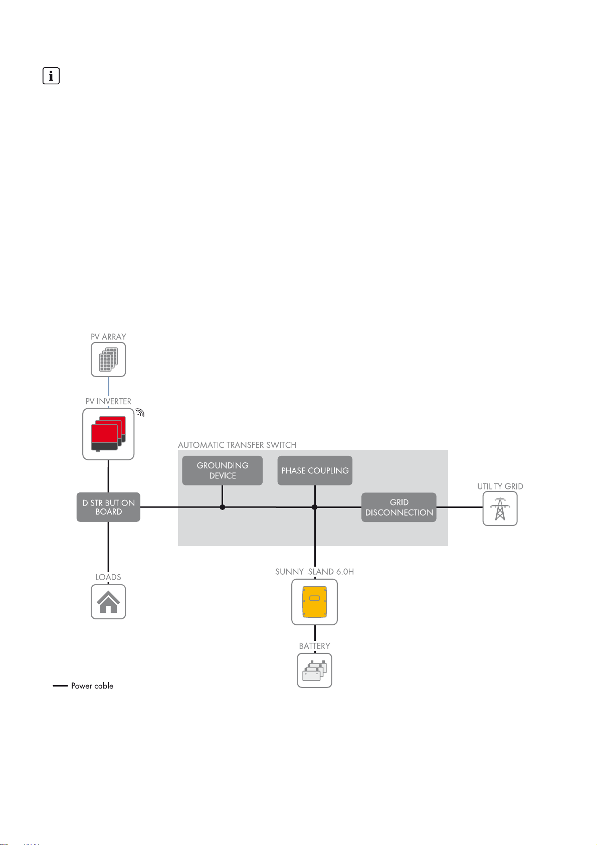
Figure1: Block circuit diagram of a single-phase battery backup system
In the event of grid failure, a battery backup system with Sunny Island supplies loads with energy and a grid-tie PV system
with voltage. In the event of grid failure, an automatic transfer switch disconnects the battery backup grid from the utility
grid. After disconnection, the loads and the PV system have no supply for approximately five seconds, until the battery
backup system can provide active and reactive power once more. The battery backup system supplies the loads and the
PV system can synchronize with the battery backup grid and feed in.
14 Ersatzstrom-IS-en-30 Installation - Quick Reference Guide
Page 15

SMA Solar Technology AG 3 Information and System Description
When the utility grid is available again, the battery backup system synchronizes the battery backup grid with the utility
grid. Following successful synchronization, the automatic transfer switch connects the battery backup grid to the utility
grid. If the automatic transfer switch is connected to the utility grid, the battery backup system uses the battery for
increased self-consumption.
You can set up and wire the automatic transfer switch yourself or acquire it pre-wired from another provider (see Planning
Guidelines "SMA Flexible Storage System with Battery Backup Function" at www.SMA-Solar.com).
Connection of loads and the PV system
The automatic transfer switch is not a distribution board for the loads or the PV system. You must also install the
necessary protective devices for the loads and the PV system.
Installation - Quick Reference Guide Ersatzstrom-IS-en-30 15
Page 16
3 Information and System Description SMA Solar Technology AG
3.4 Design and Functions of the Automatic Transfer Switch
3.4.1 Devices of the Automatic Transfer Switch
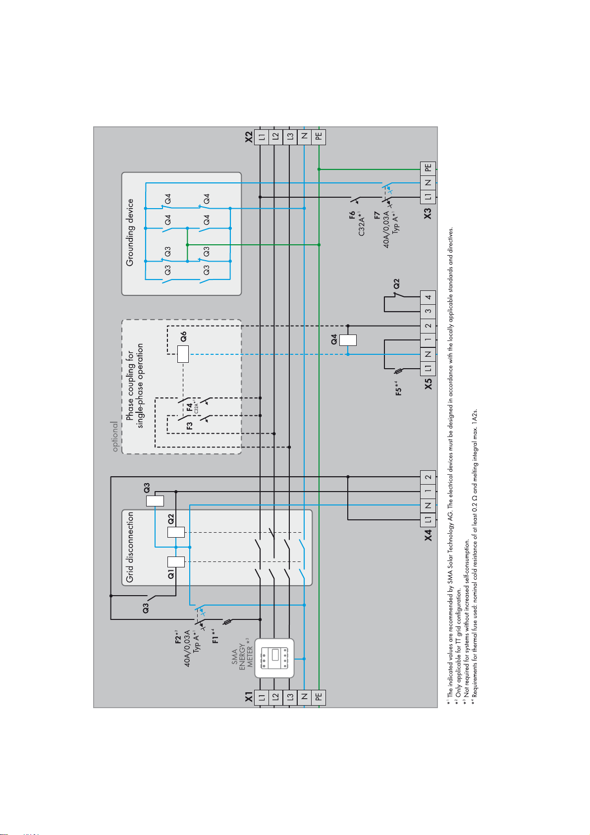
Figure2: Schematic diagram of a single-phase automatic transfer switch with all-pole disconnection and SMA Energy Meter for increased
self-consumption (example)
16 Ersatzstrom-IS-en-30 Installation - Quick Reference Guide
Page 17

SMA Solar Technology AG 3 Information and System Description
An automatic transfer switch provides the following functions:
• Grid disconnection isolates the battery backup grid from the utility grid.
• The grounding device grounds the battery backup grid after it has been disconnected from the utility grid.
The grounding device is only required in systems with all-pole disconnection.
• The phase coupling connects the line conductors of the battery backup system to a single-phase distribution grid.
The phase coupling is a function for single-phase battery backup systems if the installation of the battery backup grid
is three-phase.
• The SMA Energy Meter measures the grid feed-in and the purchased electricity.
The SMA Energy Meter is only required in systems for increased self-consumption.
3.4.2 Grid Disconnection
Within the automatic transfer switch, a tie switch disconnects the battery backup grid from the utility grid. The conditions
at the tie switch differ depending on the installation site. SMA Solar Technology AG offers two basic structures for grid
disconnection and these differ as far as the tie switch is concerned:
• Grid disconnection with all-pole disconnection of the battery backup grid from the utility grid
In the event of grid failure, a tie switch disconnects all line conductors and the neutral conductor from the utility grid.
If the technical connection requirements of the grid operator or the local standards and directives call for or allow
all-pole disconnection, you must install this basic structure. You must install all-pole disconnection in the following
countries:
–Belgium
–Denmark
–Germany
–France
–Austria
–Switzerland
• Grid disconnection without all-pole disconnection of the battery backup grid from the utility grid
In the event of grid failure, a tie switch disconnects all line conductors from the utility grid. The neutral conductor of
the battery backup grid remains permanently connected to the utility grid. If the technical connection requirements
of the grid operator or the local standards and directives prohibit disconnection of the neutral conductor, you must
install this basic structure. In Australia, you must install a battery backup system without all-pole disconnection.
Independent of the basic structure, you must adjust the ampacity of the tie switch in accordance with the requirements on
site. The tie switch must be designed for at least the operating range of the upstream fuse or the maximum short-circuit
current of the PV system.
The circuitry of the automatic transfer switch is designed in such a way that the tie switch disconnects only in the event of
a grid failure. If you stop or switch off the Sunny Island, the battery backup grid remains connected to the utility grid.
This means that you can carry out maintenance work on the battery without the supply to the loads being interrupted.
Installation - Quick Reference Guide Ersatzstrom-IS-en-30 17
Page 18

3 Information and System Description SMA Solar Technology AG
Circuit description of the tie switch with all-pole disconnection*
The tie switch with all-pole disconnection consists of contactors Q1 and Q2. The tie switch disconnects the battery backup
grid from the utility grid in the event of a grid failure or if the utility grid is outside the limiting values for voltage and
frequency.
The control voltage of contactors Q1, Q2, and Q3 is equal to the voltage of a line conductor of the utility grid. This means
that the tie switch can only be activated when grid voltage is present. An auxiliary contact of contactor Q3 locks contactor
Q1. Contactors Q3 and Q2 are controlled by the multifunction relay Relay1 of the Sunny Island inverter. If the
multifunction relay Relay1 is in non-operative mode, contactors Q2 and Q3 activate. If contactor Q3 is in non-operative
mode, contactor Q1 will also go into non-operative mode and be locked.
In the event of a total grid failure, contactors Q1, Q2, and Q3 go into non-operative mode due to lack of control voltage
and they disconnect the battery backup grid with all poles from the utility grid. The Sunny Island also measures the voltage
of the utility grid. For this, the Sunny Island is connected with the same line conductor as the control voltage of contactors
Q1, Q2, and Q3. If there is a deviation from country-specific limiting values for voltage and frequency of the utility grid,
the multifunction relay Relay1 is activated. The contactors Q1, Q2, and Q3 remain in non-operative mode or go into
non-operative mode.
When the utility grid is available again, the Sunny Island detects this. The Sunny Island synchronizes the battery backup
grid with the utility grid. Following successful synchronization, the multifunction relay Relay1 goes into non-operative
mode and contactors Q2 and Q3 are activated. Contactor Q3 unlocks contactor Q1 and Q1 is activated. The battery
backup grid is again connected to the utility grid.
Circuit description of the tie switch without all-pole disconnection**
The tie switch without all-pole disconnection consists of contactor Q2 (see Section5.1.1 "Schematic Diagram of the
Automatic Transfer Switch", page30). The tie switch disconnects the battery backup grid from the utility grid in the event
of a grid failure or if the utility grid is outside the limiting values for voltage and frequency.
The control voltage of contactor Q2 is equal to the voltage at the line conductor L1 of the utility grid. This means that the
tie switch can only be activated when grid voltage is present. Contactor Q2 is controlled by the multifunction relay
Relay1 of the Sunny Island inverter. If the multifunction relay Relay1 is in non-operative mode, contactor Q2 activates.
In the event of a total grid failure, contactor Q2 goes into non-operative mode due to lack of control voltage and
disconnects the battery backup grid from the line conductors of the utility grid. The Sun ny Island also meas ures the voltage
of the utility grid. For this, the Sunny Island is connected to the same line conductor as the control voltage of contactor
Q2. If there is a deviation from country-specific limiting values for voltage and frequency of the utility grid, the
multifunction relay Relay1 is activated. Contactor Q2 remains in non-operative mode or goes into non-operative mode.
When the utility grid is available again, the Sunny Island detects this. The Sunny Island synchronizes the battery backup
grid with the utility grid. Following successful synchronization, the multifunction relay Relay1 goes into non-operative
mode and contactor Q2 activates. The battery backup grid is again connected to the utility grid.
3.4.3 Grounding Device for the Battery Backup Grid
With TN and TT systems, the neutral conductor must be grounded for protection in the case of indirect contact with live
components. Grounding in the utility grid is usually achieved at the local grid transformer.
In automatic transfer switches with all-pole disconnection, all poles of the battery backup grid are disconnected from the
utility grid in the event of grid failure. As a result of the disconnection, the neutral conductor in the battery backup grid is
not grounded. Therefore, in automatic transfer switches with all-pole disconnection, a grounding device must ground the
neutral conductor in the event of grid failure. The grounding device enables the required protection in the event of indirect
contact with live components. The grounding device is set up for fail-safe operation.
If the neutral conductor of the battery backup grid is connected to the utility grid, there must be no further grounding in
the battery backup grid. The grounding device therefore disconnects the connection between the neutral conductor and
ground if the automatic transfer switch connects the battery backup grid to the utility grid.
* The explanation is based on a single-phase battery backup system with one Sunny Island. Three-phase battery backup systems behave in the
same way.
** The explanation is based on a single-phase battery backup system with one Sunny Island. Three-phase battery backup systems behave in the
same way.
18 Ersatzstrom-IS-en-30 Installation - Quick Reference Guide
Page 19

SMA Solar Technology AG 3 Information and System Description
Circuit Description of the Grounding Device
Contactors Q3 and Q4 form the grounding device (see Section4.1 "Single-Phase Battery Backup System", page20).
Contactors Q3 and Q4 are controlled by the two multifunction relays of the Sunny Island inverter. Contactor Q3 is
activated in parallel to contactor Q2 of the tie switch. If contactor Q2 deactivates and the tie switch opens, contactor
Q3 connects the neutral conductor in the battery backup grid to the grounding conductor. In addition, the Sunny Island
uses the multifunction relay Relay2 to control contactor Q4. If the multifunction relay Relay2 activates, contactor Q4
activates and also connects the neutral conductor to the grounding conductor. This arrangement ensures that the neutral
conductor of the battery backup grid is always connected to ground.
3.4.4 Phase Coupling for Single-Phase Battery Backup Systems
In single-phase battery backup systems, in the event of grid failure, the battery backup grid is single-phase. If the
installation of the battery backup grid is three-phase, only one part of the loads can continue to be supplied.
Phase coupling enables combination of the line conductors in the battery backup grid. As a result, the other two line
conductors are also supplied with voltage. This means that, in the event of grid failure, a three-phase battery backup grid
becomes a single-phase distribution grid.
Phase coupling can be switched on independently for the other l ine conductors. Phase coupling is only suitable for battery
backup grids with single-phase PV inverters and single-phase loads.
Circuit description of the phase coupling
Contactor Q6 is the phase coupler. If the multifunction relay Relay2 activates on the Sunny Island, contactor Q6
activates and connects the unsupplied line conductors via circuit breakers F3 and F4 with the supplied line conductor.
In the event of grid failure, the line conductor that is connected with the Sunny Island is supplied with voltage first. Then
the phase coupling combines the two other line conductors. When the utility grid is available again, the phase coupling
disconnects the combined line conductors. Only the line conductor which is connected to the Sunny Island is not
interrupted on connection to the utility grid.
Installation - Quick Reference Guide Ersatzstrom-IS-en-30 19
Page 20

4 Battery Backup Systems With All-Pole Disconnection SMA Solar Technology AG
4 Battery Backup Systems With All-Pole Disconnection
4.1 Single-Phase Battery Backup System
4.1.1 Schematic Diagram of the Automatic Transfer Switch
Figure3: Schematic diagram of the single-phase automatic transfer switch with all-pole disconnection and optional SMA Energy Meter
20 Ersatzstrom-IS-en-30 Installation - Quick Reference Guide
Page 21

SMA Solar Technology AG 4 Battery Backup Systems With All-Pole Disconnection
4.1.2 Circuitry Overview
Figure4: Connection of the automatic transfer switch with all-pole disconnection (e.g., for Germany)
Installation - Quick Reference Guide Ersatzstrom-IS-en-30 21
Page 22
4 Battery Backup Systems With All-Pole Disconnection SMA Solar Technology AG
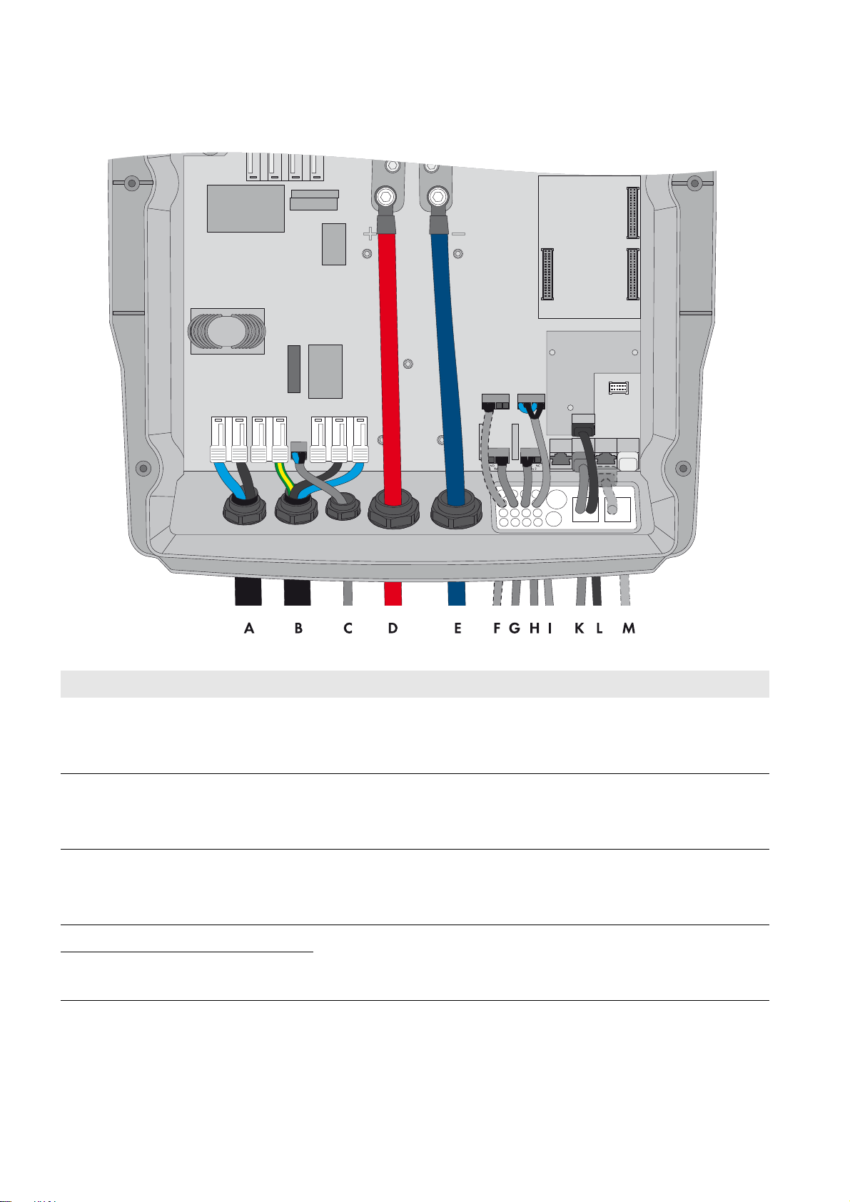
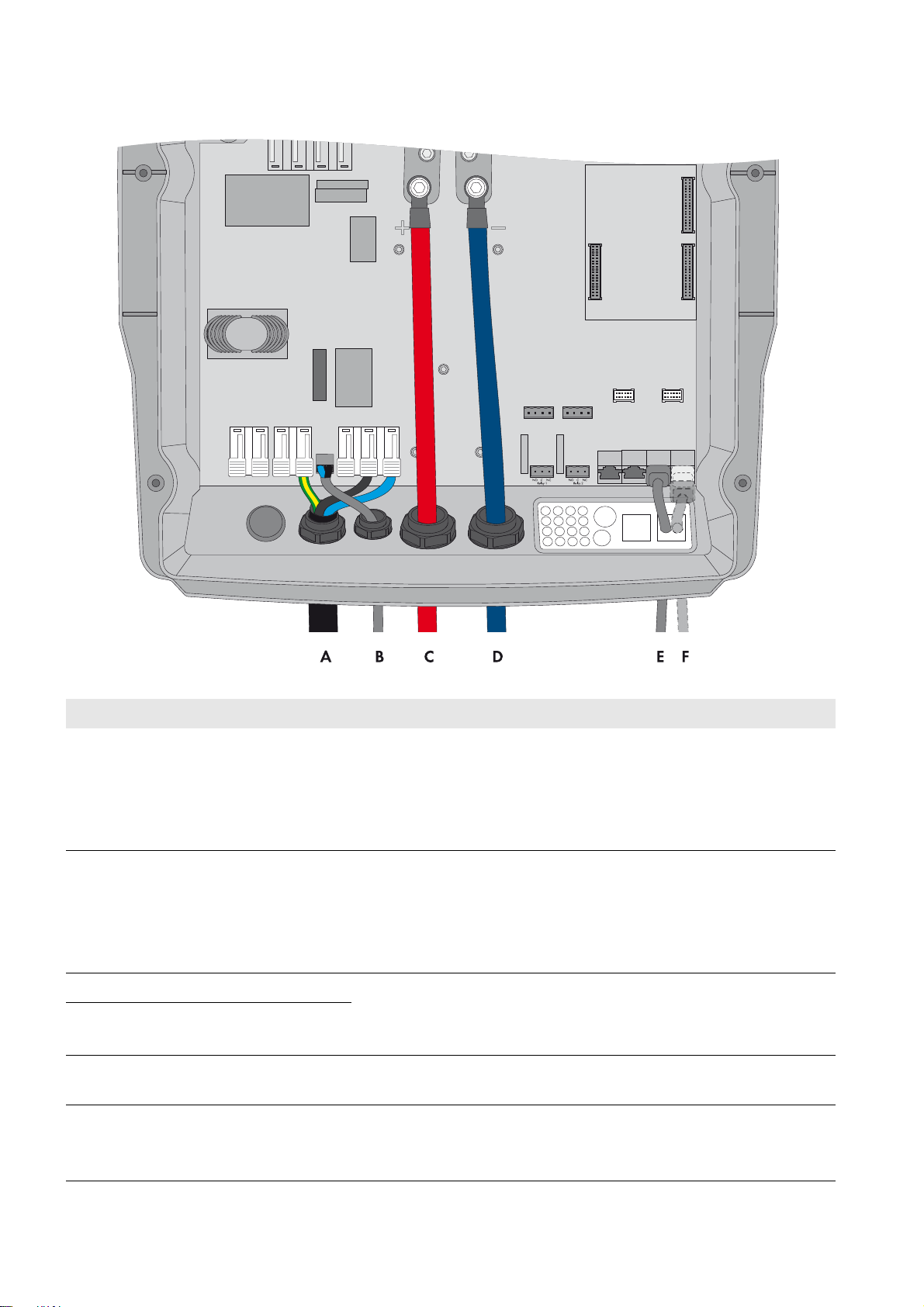
4.1.3 Connecting the Sunny Island Inverter
Figure5: Connecting the Sunny Island inverter
Position Designation Description/information
A Cable for the control voltage Sunny Island: connection AC1 Loads/SunnyBoys terminals L and N
Automatic transfer switch: connection X5 terminals L and N
Conductor cross-section: 2.5 mm² to 16 mm²
B AC power cable Sunny Island: connection AC2 Gen/Grid terminals L, N
and PE
TT,
Automatic transfer switch: connection X3 terminals L1, N, and PE
Conductor cross-section: 10 mm² to 16 mm²
C Measuring cable for voltage
measurement
Sunny Island: connection ExtVtg terminals L and N
Automatic transfer switch: connection X4 terminals L1 and N
Conductor cross-section: 1.5 mm² to 2.5 mm²
D DC+ cable Battery connection
E DC − cable
Conductor cross-section: 50 mm² to 95 mm²
Cable diameter: 14 mm to 25 mm
22 Ersatzstrom-IS-en-30 Installation - Quick Reference Guide
Page 23

SMA Solar Technology AG 4 Battery Backup Systems With All-Pole Disconnection
Position Designation Description/information
F Measuring cable of the
battery temperature sensor
G Control cable of the tie
switch
H Control cable of contactors
Q4 and Q6
IMeasuring cable for
monitoring the tie switch
Sunny Island: BatTmp connection
You only have to connect a battery temperature sensor if lead-acid batteries
are used.
Mount the battery temperature sensor in the middle of the battery
connection, in the upper third of the battery cell.
Sunny Island: connection Relay1 terminals C and NC
Automatic transfer switch: connection X4 terminals 1 and 2
If the multifunction relay activates, the contactors of the tie switch deactivate.
Conductor cross-section: 1.5 mm² to 2.5 mm²
Sunny Island: connection Relay2 terminals C and NO
Automatic transfer switch: connection X5 terminals 1 and 2
If the multifunction relay activates, the contactors activate.
Conductor cross-section: 1.5 mm² to 2.5 mm²
Sunny Island: connections DigIn+ and BatVtgOut+
Automatic transfer switch: connection X5 terminals 3 and 4
Inside the Sunny Island inverter, connect connections DigIn − and
BatVtgOut − .
Conductor cross-section: 0.2 mm² to 2.5 mm²
K Data cable to
Sunny Remote Control
L Speedwire network cable Sunny Island: ComETH connection
M Data cable for battery
management
Sunny Island: Display connection
In order to connect the router/network switch, the Speedwire data module
Sunny Island must be mounted in the Sunny Island (see Sunny Island
Speedwire data module installation manual). The ComETH connection is on
the data module.
Sunny Island: ComSync In connection
You only have to connect a data cable to the battery if lithium-ion batteries
are used. The communication bus must be equipped with a termina
both ends.
tor on
Installation - Quick Reference Guide Ersatzstrom-IS-en-30 23
Page 24
4 Battery Backup Systems With All-Pole Disconnection SMA Solar Technology AG
4.2 Three-Phase Battery Backup System
4.2.1 Schematic Diagram of the Automatic Transfer Switch
Figure6: Schematic diagram of the three-phase automatic transfer switch with all-pole disconnection and optional SMA Energy Meter
24 Ersatzstrom-IS-en-30 Installation - Quick Reference Guide
Page 25

SMA Solar Technology AG 4 Battery Backup Systems With All-Pole Disconnection
4.2.2 Circuitry Overview
Figure7: Connection of the automatic transfer switch with all-pole disconnection (e.g., for Germany)
Installation - Quick Reference Guide Ersatzstrom-IS-en-30 25
Page 26

4 Battery Backup Systems With All-Pole Disconnection SMA Solar Technology AG
4.2.3 Connecting the Master
Figure8: Connecting the master
Position Designation Description/information
A Cable for the control voltage Sunny Island: connection AC1 Loads/SunnyBoys terminals L and N
Automatic transfer switch: connection X5 terminals L and N
Conductor cross-section: 2.5 mm² to 16 mm²
B AC power cable Sunny Island: connection AC2 Gen/Grid terminals L, N
and PE
TT,
Automatic transfer switch: connection X3 terminals L1, N, and PE
Conductor cross-section: 10 mm² to 16 mm²
C Measuring cable for voltage
measurement
Sunny Island: connection ExtVtg terminals L and N
Automatic transfer switch: connection X4 terminals L1 and N
Conductor cross-section: 1.5 mm² to 2.5 mm²
D DC+ cable Battery connection
E DC − cable
Conductor cross-section: 50 mm² to 95 mm²
Cable diameter: 14 mm to 25 mm
F Measuring cable of the
battery temperature sensor
Sunny Island: BatTmp connection
You only have to connect a battery temperature sensor if lead-acid
batteries are used.
Mount the battery temperature sensor in the middle of the battery
connection, in the upper third of the battery cell.
26 Ersatzstrom-IS-en-30 Installation - Quick Reference Guide
Page 27

SMA Solar Technology AG 4 Battery Backup Systems With All-Pole Disconnection
Position Designation Description/information
G Control cable of the tie
switch
H Control cable of contactor Q4Sunny Island: connection Relay2 terminals C and NO
I Measuring cable for
monitoring the tie switch
K Data cable to
Sunny Remote Control
L Speedwire network cable Sunny Island: ComETH connection
Sunny Island: connection Relay1 terminals C and NC
Automatic transfer switch: connection X4 terminals 1 and 2
If the multifunction relay activates, the contactors of the tie switch
deactivate.
Conductor cross-section: 1.5 mm² to 2.5 mm²
Automatic transfer switch: connection X5 terminals 1 and 2
If the multifunction relay activates, contactor Q4 activates.
Conductor cross-section: 1.5 mm² to 2.5 mm²
Sunny Island: connections DigIn+ and BatVtgOut+
Automatic transfer switch: connection X5 terminals 3 and 4
Inside the Sunny Island inverter, connect connections DigIn − and
BatVtgOut − .
Conductor cross-section: 0.2 mm² to 2.5 mm²
Sunny Island: Display connection
In order to connect the router/network switch, the Speedwire data module
Sunny Island must be mounted in the Sunny Island (see Sunny Island
Speedwire data module installation manual). The ComETH connection is
on the data module.
M Data cable for battery
management
N Data cable for the internal
communication in the cluster
Sunny Island: ComSync In connection
You only have to connect a data cable to the battery if lithium-ion batteries
are used. The communication bus must be equipped with a terminator on
both ends.
Sunny Island: ComSync Out connection
Connection of internal communication bus of slave 1
Installation - Quick Reference Guide Ersatzstrom-IS-en-30 27
Page 28
4 Battery Backup Systems With All-Pole Disconnection SMA Solar Technology AG
4.2.4 Connecting the Slaves
Figure9: Connecting the slaves
Position Designation Description/information
A AC power cable Sunny Island: connection AC2 Gen/Grid terminals L, N
Automatic transfer switch:
Connect slave 1 to X3 terminals L2, N, and PE.
Connect slave 2 to X3, terminals L3, N, and PE.
Conductor cross-section: 10 mm² to 16 mm²
B Measuring cable for voltage
measurement
Sunny Island: connection ExtVtg terminals L and N
Automatic transfer switch:
Connect slave 1 to X4 terminals L2 and N.
Connect slave 2 to X4 terminals L3 and N.
Conductor cross-section: 1.5 mm² to 2.5 mm²
C DC+ cable Battery connection
D DC − cable
Conductor cross-section: 50 mm² to 95 mm²
Cable diameter: 14 mm to 25 mm
E Data cable for the internal
communication in the cluster
Sunny Island: ComSync In connection
With slave 1: connection of internal communication bus of master
and PE
TT,
With slave 2: connection of internal communication bus of slave 1
28 Ersatzstrom-IS-en-30 Installation - Quick Reference Guide
Page 29

SMA Solar Technology AG 4 Battery Backup Systems With All-Pole Disconnection
Position Designation Description/information
F Data cable for the internal
communication in the cluster
Sunny Island: ComSync Out connection
With slave 1: connection of internal communication bus after slave 2
With slave 2: leave terminator plugged in. Slave 2 is connected to slave 1
only.
Installation - Quick Reference Guide Ersatzstrom-IS-en-30 29
Page 30

5 Battery Backup Systems Without All-Pole Disconnection SMA Solar Technology AG
5 Battery Backup Systems Without All-Pole Disconnection
5.1 Single-Phase Battery Backup System
5.1.1 Schematic Diagram of the Automatic Transfer Switch
Figure10: Schematic diagram of the single-phase automatic transfer switch without all-pole disconnection and optional SMA Energy Meter
30 Ersatzstrom-IS-en-30 Installation - Quick Reference Guide
Page 31

SMA Solar Technology AG 5 Battery Backup Systems Without All-Pole Disconnection
5.1.2 Circuitry Overview
Figure11: Connection of the automatic transfer switch without all-pole disconnection (e.g., for Australia)
Installation - Quick Reference Guide Ersatzstrom-IS-en-30 31
Page 32

5 Battery Backup Systems Without All-Pole Disconnection SMA Solar Technology AG
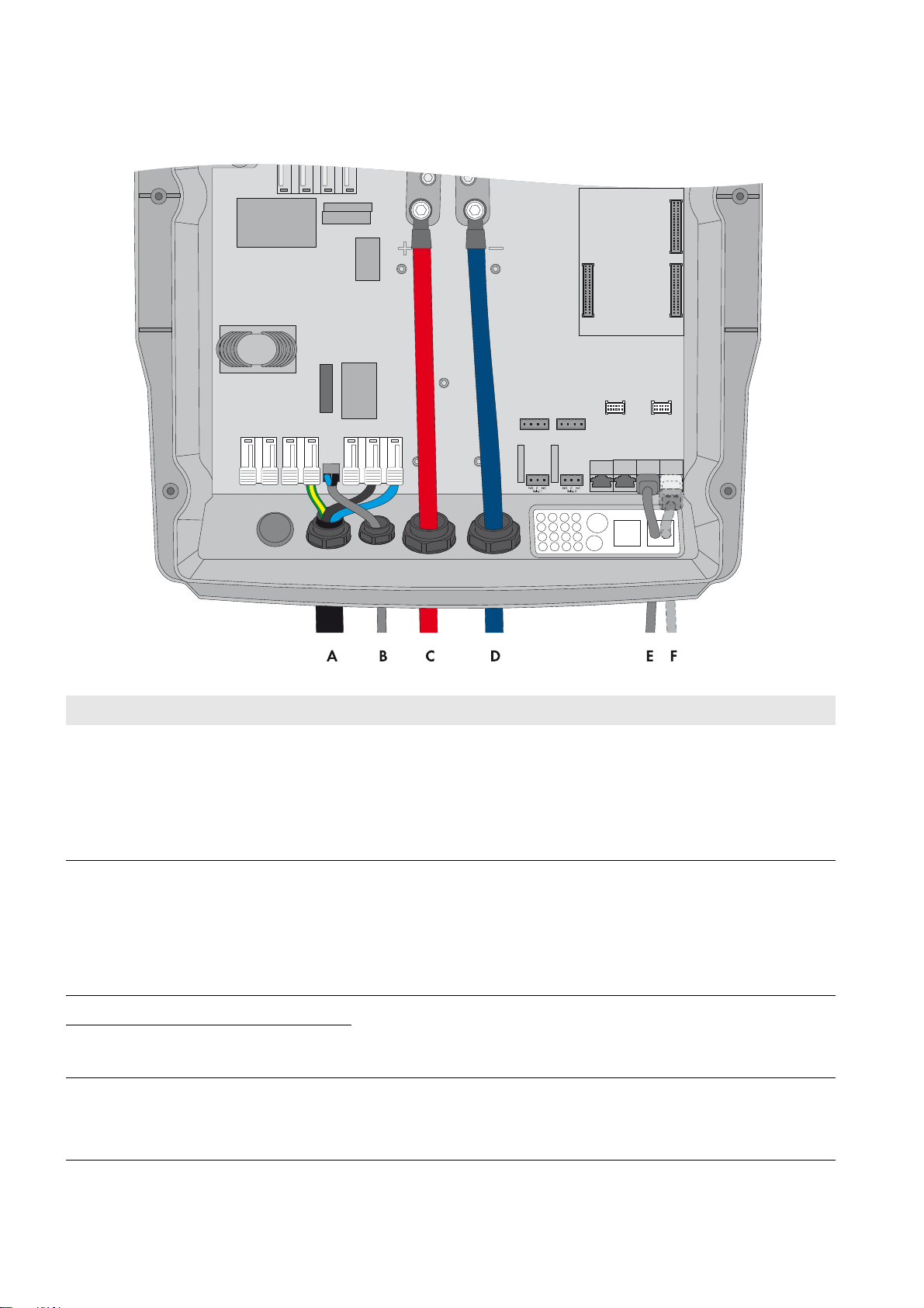
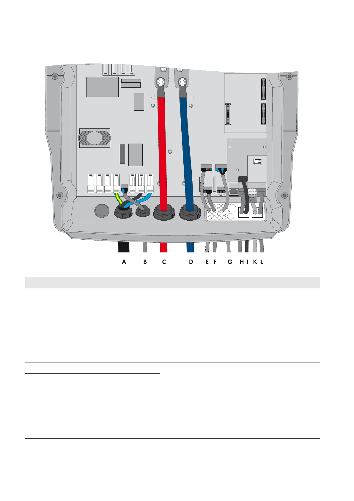
5.1.3 Connecting the Sunny Island Inverter
Figure12: Connecting the Sunny Island inverter
Position Designation Description/information
A Cable for the control voltage Sunny Island: connection AC1 Loads/SunnyBoys terminals L and N
Automatic transfer switch: connection X5 terminals L and N
This cable is only required for phase coupling.
Conductor cross-section: 2.5 mm² to 16 mm²
B AC power cable Sunny Island: connection AC2 Gen/Grid terminals L, N
and PE
TT,
Automatic transfer switch: connection X3 terminals L1, N, and PE
Conductor cross-section: 10 mm² to 16 mm²
C Measuring cable for voltage
measurement
Sunny Island: connection ExtVtg terminals L and N
Automatic transfer switch: connection X4 terminals L1 and N
Conductor cross-section: 1.5 mm² to 2.5 mm²
D DC+ cable Battery connection
E DC − cable
Conductor cross-section: 50 mm² to 95 mm²
Cable diameter: 14 mm to 25 mm
F Measuring cable of the
battery temperature sensor
Sunny Island: BatTmp connection
You only have to connect a battery temperature sensor if lead-acid batteries
are used. Mount the battery temperature sensor in the middle of the battery
connection, in the upper third of the battery cell.
32 Ersatzstrom-IS-en-30 Installation - Quick Reference Guide
Page 33

SMA Solar Technology AG 5 Battery Backup Systems Without All-Pole Disconnection
Position Designation Description/information
G Control cable of the tie
switch
H Control cable of contactor Q6Sunny Island: connection Relay2 terminals C and NO
IMeasuring cable for
monitoring the tie switch
K Data cable to
Sunny Remote Control
L Speedwire network cable Sunny Island: ComETH connection
Sunny Island: connection Relay1 terminals C and NC
Automatic transfer switch: connection X4 terminals 1 and 2
If the multifunction relay activates, the contactor of the tie switch deactivates.
Conductor cross-section: 1.5 mm² to 2.5 mm²
Automatic transfer switch: connection X5 terminals 1 and 2
If the multifunction relay activates, the contactor activates. This cable is only
required for phase coupling. Conductor cross-section: 1.5 mm² to 2.5 mm²
Sunny Island: connections DigIn+ and BatVtgOut+
Automatic transfer switch: connection X5 terminals 3 and 4
Inside the Sunny Island inverter, connect connections DigIn − and
BatVtgOut − . Conductor cross-section: 0.2 mm² to 2.5 mm²
Sunny Island: Display connection
In order to connect the router/network switch, the Speedwire data module
Sunny Island must be mounted in the Sunny Island (see Sunny Island
Speedwire data module installation manual). The ComETH connection is on
the data module.
M Data cable for battery
management
Sunny Island: ComSync In connection
You only have to connect a data cable to the battery if lithium-ion batteries
are used. The communication bus must be equipped with a terminator on
both ends.
Installation - Quick Reference Guide Ersatzstrom-IS-en-30 33
Page 34

5 Battery Backup Systems Without All-Pole Disconnection SMA Solar Technology AG
5.2 Three-Phase Battery Backup System
5.2.1 Schematic Diagram of the Automatic Transfer Switch
Figure13: Schematic diagram of the three-phase automatic transfer switch without all-pole disconnection and optional SMA Energy Meter
34 Ersatzstrom-IS-en-30 Installation - Quick Reference Guide
Page 35

SMA Solar Technology AG 5 Battery Backup Systems Without All-Pole Disconnection
5.2.2 Circuitry Overview
Figure14: Connection of the automatic transfer switch (e.g., for Australia)
Installation - Quick Reference Guide Ersatzstrom-IS-en-30 35
Page 36
5 Battery Backup Systems Without All-Pole Disconnection SMA Solar Technology AG
5.2.3 Connecting the Master
Figure15: Connecting the master
Position Designation Description/information
A AC power cable Sunny Island: connection AC2 Gen/Grid terminals L, N
PE
Automatic transfer switch: connection X3 terminals L1, N, and
PE
Conductor cross-section: 10 mm² to 16 mm²
B Measuring cable for voltage
measurement
Sunny Island: connection ExtVtg terminals L and N
Automatic transfer switch: connection X4 terminals L1 and N
Conductor cross-section: 1.5 mm² to 2.5 mm²
C DC+ cable Battery connection
D DC − cable
Conductor cross-section: 50 mm² to 95 mm²
Cable diameter: 14 mm to 25 mm
E Measuring cable of the battery
temperature sensor
Sunny Island: BatTmp connection
You only have to connect a battery temperature sensor if
lead-acid batteries are used. Mount the battery temperature
sensor in the middle of the battery connection, in the upper third
of the battery cell.
TT,
and
36 Ersatzstrom-IS-en-30 Installation - Quick Reference Guide
Page 37

SMA Solar Technology AG 5 Battery Backup Systems Without All-Pole Disconnection
Position Designation Description/information
F Control cable of the tie switch Sunny Island: connection Relay1 terminals C and NC
Automatic transfer switch: connection X4 terminals 1 and 2
If the multifunction relay activates, the contactor of the tie switch
deactivates. Conductor cross-section: 1.5 mm² to 2.5 mm²
G Measuring cable for monitoring the tie
switch
I Data cable to Sunny Remote Control Sunny Island: Display connection
K Speedwire network cable Sunny Island: ComETH connection
L Data cable for battery management Sunny Island: ComSync In connection
M Data cable for the internal
communication in the cluster
Sunny Island: connections DigIn+ and BatVtgOut+
Automatic transfer switch: connection X5 terminals 3 and 4
Inside the Sunny Island inverter, connect connections DigIn −
and BatVtgOut − .
Conductor cross-section: 0.2 mm² to 2.5 mm²
In order to connect the router/network switch, the Speedwire
data module Sunny Island must be mounted in the Sunny Island
(see Sunny Island Speedwire data module installation manual).
The ComETH connection is on the data module.
You only have to connect a data cable to the battery if
lithium-ion batteries are used. The communication bus must be
equipped with a terminator on both ends.
If no data cable is plugged in, plug the terminator into
ComSync In.
Sunny Island: ComSync Out connection
Installation - Quick Reference Guide Ersatzstrom-IS-en-30 37
Page 38
5 Battery Backup Systems Without All-Pole Disconnection SMA Solar Technology AG
5.2.4 Connecting the Slaves
Figure16: Connecting the slaves
Position Designation Description/information
A AC power cable Sunny Island: connection AC2 Gen/Grid terminals L, N
Automatic transfer switch:
Connect slave 1 to X3 terminals L2, N, and PE.
Connect slave 2 to X3, terminals L3, N, and PE.
Conductor cross-section: 10 mm² to 16 mm²
B Measuring cable for voltage
measurement
Sunny Island: connection ExtVtg terminals L and N
Automatic transfer switch:
Connect slave 1 to X4 terminals L2 and N.
Connect slave 2 to X4 terminals L3 and N.
Conductor cross-section: 1.5 mm² to 2.5 mm²
C DC+ cable Battery connection
D DC − cable
Conductor cross-section: 50 mm² to 95 mm²
Cable diameter: 14 mm to 25 mm
E Data cable for the internal
Sunny Island: ComSync In connection
communication in the cluster
F Data cable for the internal
communication in the cluster
Sunny Island: ComSync Out connection
With slave 2, leave terminator plugged in.
Slave 2 is connected to slave 1 only.
and PE
TT,
38 Ersatzstrom-IS-en-30 Installation - Quick Reference Guide
Page 39

SMA Solar Technology AG 6 Connecting the Sunny Home Manager
6 Connecting the Sunny Home Manager
Figure17: Connection of the Sunny Home Manager in systems with an SMA Energy Meter
Requirements:
☐ All Speedwire devices must be connected to the same router or network switch.
☐ The router and optionally the network switch must fully support Multicast.
☐ The router must support "Internet Enabled Devices" with the interfaces SIP and STUN.
The most common routers and network switches support Multicast and "Internet Enabled Devices".
Installation - Quick Reference Guide Ersatzstrom-IS-en-30 39
Page 40

7 Commissioning SMA Solar Technology AG
/05*$&
7 Commissioning
7.1 Basic Configuration of the Sunny Island Inverter
Damage to the battery due to incorrect settings
Aging of the battery will be accelerated by incorrect settings of the parameters for battery type, nominal voltage,
and battery capacity. The battery parameters influence the charging behavior of the Sunny Island inverter.
• During the basic configuration, ensure that you configure the battery values recommended by the battery
manufacturer (for the battery technical data, see the documentation of the battery manufacturer).
• In the basic configuration, configure the battery capacity for a ten-hour electric discharge (C10). The battery
manufacturer specifies the battery capacity in relation to discharge time.
Requirements:
☐ With a three-phase system, the Sunny Remote Control must be connected to the master. The master is thus defined
during basic configuration.
☐ In the automatic transfer switch, all circuit breakers must be open. This means that the Sunny Island is not connected
to any PV inverter.
Procedure:
Check the wiring
(see the Sunny Island inverter installation manual).
Close all devices except the BatFuse.
This protects all live components from being touched.
Close the BatFuse and switch on all Sunny Island inverters:
In systems with one Sunny Island, press the "On" button.
In systems with three Sunny Island inverters, press and hold the "On" button on
the master until an acoustic signal sounds.
40 Ersatzstrom-IS-en-30 Installation - Quick Reference Guide
Page 41

SMA Solar Technology AG 7 Commissioning
When the Sunny Remote Control shows <Init System>,
press and hold the button on the Sunny Remote Control.
☑ An acoustic signal sounds three times and the
Sunny Remote Control displays the
Quick Configuration Guide.
Turn the button on the Sunny Remote Control and select
New System.
Press the button. This confirms your selection of New System.
☑ An entry confirmation prompt appears.
Set Y and press the button.
Set the date.
Set the time.
Set OnGrid.
Installation - Quick Reference Guide Ersatzstrom-IS-en-30 41
Page 42
7 Commissioning SMA Solar Technology AG
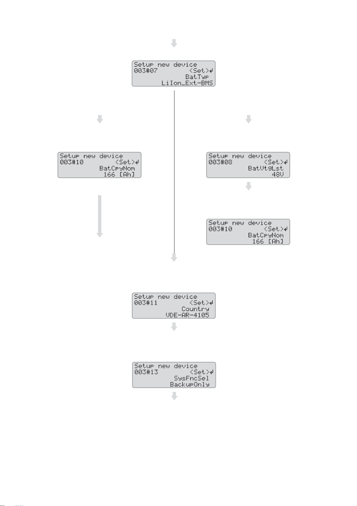
Set the battery type.
LiIon_Ext-BMS: lithium-ion battery VRLA: lead-acid battery with electrolyte absorbed in glass
mat or immobilized in gel
FLA: lead-acid battery with liquid electrolyte
Set the battery capacity for ten-hour electric discharge
(for determining the battery capacity, see the Sunny Island
inverter installation manual).
Also, during the first ten operating hours, set the country data set:
AR-N4105: configuration in accordance with the application rule VDE-AR-N 4105
AS4777: configuration in accordance with the standard AS4777
Set the nominal voltage of the battery.
Set the battery capacity for ten-hour electric discharge
(for determining the battery capacity, see the Sunny Island
inverter installation manual).
Set increased self-consumption:
BackupOnly: system without increased self-consumption
SelfConsBackup: system with increased self-consumption
42 Ersatzstrom-IS-en-30 Installation - Quick Reference Guide
Page 43

SMA Solar Technology AG 7 Commissioning
Set the number of Sunny Island inverters in the system:
1Phase: system with one Sunny Island inverter 3Phase: system with three
Sunny Island inverters
If the country data set of the Sunny Island inverter is
VDE-AR-4105 and the system increases self-consumption
(SelfConsBackup), set the type of feed-in of the PV system
(see Section3.1, page12).
Asymmetric: The
installation site is located in
Germany and at least one PV
inverter feeds in
asymmetrically on a single
line conductor.
Set the line conductor to
which the Sunny Island is
connected:
Symmetric: The installation
site is either located outside
of Germany or all PV
inverters feed in
symmetrically on three line
conductors.
Confirm the basic
configuration with Y.
If the system does not
increase self-consumption
(BackupOnly) or the
country data set of the
Sunny Island inverter is
AS4777, confirm the basic
configuration with Y.
Confirm the basic
configuration with Y.
Wait until the upper LED
(inverter LED) on slave 1 is
flashing and the Sunny
Remote Control is displaying
To identify Slave1, press
Tss on the Slv.
Press the start-stop button on
slave 1.
L1: connection to line
conductor L1
L2: connection to line
conductor L2
L3: connection to line
conductor L3
Confirm the basic
configuration with Y.
Installation - Quick Reference Guide Ersatzstrom-IS-en-30 43
Wait until the upper LED
(inverter LED) on slave 2 is
flashing and the Sunny
Remote Control is displaying
To identify Slave2, press
Tss on the Slv.
Page 44
7 Commissioning SMA Solar Technology AG
:$5 1,1*
☑ The basic configuration is complete.
If an SD memory card is inserted in the Sunny Remote Control, the message
Do not remove MMC/SD memory card ... appears.
Close the circuit breaker F1 and the residual-current device F2 in the distribution board
and leave the Sunny Island switched on, but do not start it.
7.2 Testing the Automatic Transfer Switch Function
Danger to life from electric shock due to live voltage
During the test, high voltages are present in the automatic transfer switch. Touching live components can result in death
or serious injury.
• Ensure that you do not touch any live components while measuring and testing.
• Disconnect the automatic transfer switch from voltage sources while you are eliminating any faults.
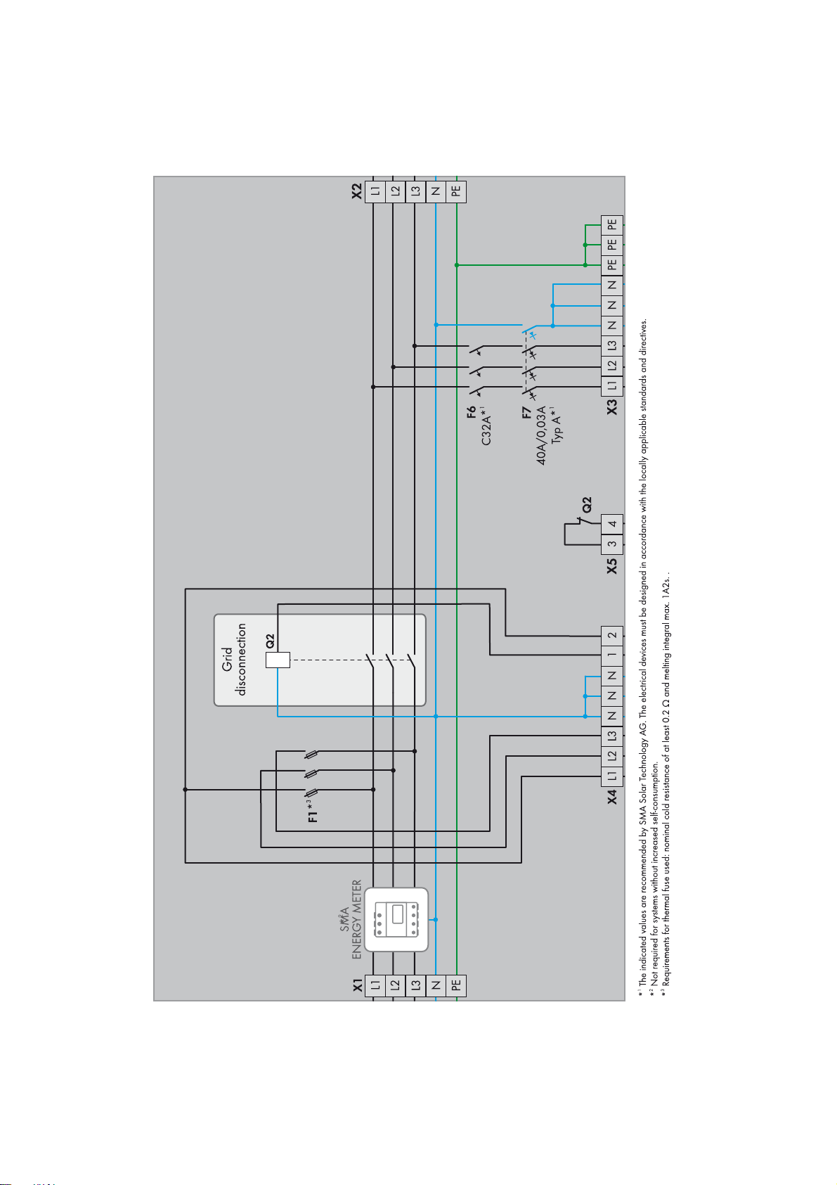
The sequence of the test applies to all types of automatic transfer switches and is independent of the automatic transfer
switch installed. Ignore tests for non-existent devices.
Requirements:
☐ In the automatic transfer switch, all circuit breakers F1, F3, …, F6 must be open.
☐ The residual-current devices F2 and F7 must be closed.
☐ All Sunny Island inverters must be switched on but not operational.
☐ PV system and all loads at connection X2 must be disconnected from voltage sources.
Procedure:
1. Open the automatic transfer switch and ensure that at connection X1, there is voltage present and a right-hand
rotating magnetic field.
2. Measure whether the individual terminals are voltage-free:
Check point Task
Connection X2 If AC voltage is present, correctly wire contactors Q1 and Q2.
Connection X3 If AC voltage is present, stop the Sunny Island.
Connection X4 If AC voltage is present, correctly wire circuit breaker F1.
Connection X5, terminals L1, N,
1, and 2
If AC voltage is present, stop the Sunny Island.
Connection X5, terminals 3 and 4If DC voltage is present, correctly wire contactor or auxiliary contact Q2.
3. Check whether the grounding device is correctly wired:
Check point Task
Contactors Q3 and Q4 Ensure that the wiring is correct.
Connection X2, terminals N and PEEnsure that no voltage is present between the terminals and that conductivity
can be measured.
44 Ersatzstrom-IS-en-30 Installation - Quick Reference Guide
Page 45
SMA Solar Technology AG 7 Commissioning
4. Close circuit breaker F1 and check the following:
Check point Task
Contactors Q1, Q2, and Q3 Check whether the contactors activate and whether there is voltage present and
Connection X2
5. Close circuit breaker F6.
☑ Voltages are present at connection X3.
6. Check whether the residual-current devices trip correctly and are correctly wired:
Check point Task
Residual-current device F7 Press the test button and measure whether there is voltage present at connection
a right-hand rotating magnetic field at connection X2.
If the contactors do not activate or no voltage is present at connection X2,
ensure the following:
• At the master, ensure that the control cable is correctly connected to
connections Relay1 C and Relay1 NC.
• Ensure that, in the automatic transfer switch, contactors Q1, Q2, and Q3
are correctly wired.
X3.
If voltage is present, correctly wire residual-current device F7.
Switch on residual-current device F7 again.
Residual-current device F2 Press the test button and check if contactors Q1, Q2, and Q3 go into
non-operative mode.
If the contactors do not deactivate, wire the residual-current device F2 correctly.
Switch on residual-current device F2 again.
7. Start the Sunny Island. Press and hold the button on the Sunny Remote Control until you hear an acoustic signal.
8. Check whether error messages are displayed on the Sunny Remote Control.
If the error message F365 VAcExtPhsFail is displayed, correctly connect connection ExtVtg on the Sunny Island.
9. Close circuit breaker F5 and check whether contactors Q4 and Q6 remain in non-operative mode.
If the contactors activate, correctly wire connections Relay2 C and Relay2 NO on the Sunny Island.
10. Simulate a grid failure. To do this, open circuit breaker F1. As a result, contactors Q1, Q2, and Q3 deactivate.
If the error message F367 ExtCtcNotOpen is displayed, correctly connect connections DigIn and BatVtgOut to
the Sunny Island.
11. Check whether contactors Q4 and Q6 activate approximately five seconds after circuit breaker F1 is opened.
If the contactors do not activate, correctly wire the control cables of the contactors and correctly connect connections
Relay2 C and Relay2 NO to the master.
12. Check whether the grounding device switches correctly.
• Ensure that no voltage is present at connection X2 between terminals N and PE and that conductivity can be
measured.
• Open circuit breaker F5.
• Ensure that no voltage is present at connection X2 between terminals N and PE and that conductivity can be
measured.
• Close circuit breaker F5.
Installation - Quick Reference Guide Ersatzstrom-IS-en-30 45
Page 46

7 Commissioning SMA Solar Technology AG
13. Check whether the phase coupling switches correctly. To do this, close circuit breakers F3 and F4 and check the
following:
Check point Task
Connection X2 Measure if there is voltage present between the line conductors and the neutral
conductor.
If no voltage is present, correctly wire contactor Q6.
Ensure that no voltage is present between the line conductors.
14. Switch on circuit breaker F1.
• Contactors Q4 and Q6 deactivate within five minutes and the tie switch then connects the battery backup grid
to the utility grid.
7.3 Adjusting the Configuration of the Sunny Island Inverter
7.3.1 Countries in Which the Configuration Must Be Adjusted
In the SMA Flexible Storage System, the Sunny Island inverters are connected to the utility grid and must meet the
requirements of the grid operators. Depending on the settings, the Sunny Island inverters satisfy the requirements of the
application rule VDE-AR-N 4105:2011-08 or the standard AS4777. The application rule is stored in the Sunny Island
as the standard country data set VDE-AR-4105 or AS4777.
The configuration must be adjusted for the following countries (status: July 2014):
• Denmark (see Section7.3.2, page47)
• France (see Section7.3.3, page47)
• Austria (see Section7.3.4, page47)
• Switzerland (see Section7.3.5, page48)
The configuration may only be adjusted on request or with permission of the grid operator in the following countries
(status: July 2014):
•Australia
Country data set: AS4777
•Belgium
Country data set: VDE-AR-4105
•Germany
Country data set: VDE-AR-4105
Use in other countries is possible with the agreement of the grid operator. Consult the grid operator on whether
adjustment is necessary.
46 Ersatzstrom-IS-en-30 Installation - Quick Reference Guide
Page 47

SMA Solar Technology AG 7 Commissioning
7.3.2 Adjusting the Configuration for Denmark
When using the Sunny Island 6.0H / 8.0H in Denmark, you must reduce the discharge/charging current (default setting:
max. 20.0 A).
When using the Sunny Island 3.0M / 4.4M in Denmark, you can retain the default setting of the discharge/charging
current (default setting: max. 16.0 A).
Requirement:
☐ The extended configuration must be performed within the first ten operating hours of the Sunny Island inverter,
otherwise an SMA Grid Guard code is required in order to change grid-relevant parameters (application form for
the SMA Grid Guard code available at www.SMA-Solar.com).
☐ The country data set of the Sunny Island inverter must be set to VDE-AR-4105 (see Section7.1 "Basic Configuration
of the Sunny Island Inverter", page40).
Procedure:
1. Switch to expert mode on the Sunny Remote Control (see the Sunny Island inverter operating manual).
2. Set the parameter 210.03 InvChrgCurMax to 16.0 A.
7.3.3 Adjusting the Configuration for France
The following limiting values must be adjusted in order to meet the requirements of the Union technique de l’électricité
(UTE):
• Maximum power frequency
• The upper frequency difference for valid grid connection
• Minimum observation time for grid voltage and frequency before grid connection
Requirement:
☐ The extended configuration must be performed within the first ten operating hours of the Sunny Island inverter,
otherwise an SMA Grid Guard code is required in order to change grid-relevant parameters (application form for
the SMA Grid Guard code available at www.SMA-Solar.com).
☐ The country data set of the Sunny Island inverter must be set to VDE-AR-4105 (see Section7.1 "Basic Configuration
of the Sunny Island Inverter", page40).
Procedure:
1. Switch to expert mode on the Sunny Remote Control (see the Sunny Island inverter operating manual).
2. Set the parameter 232.07 GdFrqMax to 50.6 Hz.
3. Set the parameter 232.15 GdFrqMaxDel to 0.05 Hz.
4. Set the parameter 232.08 GdVldTm to 30 s.
7.3.4 Adjusting the Configuration for Austria
If your grid operator does not permit frequency-dependent control of active power feed-in in the case of overfrequency,
you must switch off this function (see VDE-AR-N 4105 item 5.7.3.3).
If your grid operator specifies a maximum grid feed-in per line conductor, you must reduce the discharge/charging
current (default setting in the Sunny Island is 20.0 A).
Requirement:
☐ The extended configuration must be performed within the first ten operating hours of the Sunny Island inverter,
otherwise an SMA Grid Guard code is required in order to change grid-relevant parameters (application form for
the SMA Grid Guard code available at www.SMA-Solar.com).
☐ The country data set of the Sunny Island inverter must be set to VDE-AR-4105 (see Section7.1 "Basic Configuration
of the Sunny Island Inverter", page40).
Installation - Quick Reference Guide Ersatzstrom-IS-en-30 47
Page 48

7 Commissioning SMA Solar Technology AG
Procedure:
1. Switch to expert mode on the Sunny Remote Control (see the Sunny Island inverter operating manual).
2. If frequency-dependent control of active power feed-in is not permitted, set the parameter 232.41 P-WCtLHzMod
to Off.
3. If your grid operator specifies a maximum grid feed-in per line conductor, set the parameter
210.03 InvChrgCurMax to the value specified by the grid operator.
7.3.5 Adjusting the Configuration for Switzerland
The following limiting values must be adjusted in order to meet the requirements of the grid operators in Switzerland:
• Maximum power frequency
• The upper frequency difference for valid grid connection
• Minimum observation time for grid voltage and frequency before grid connection
If your grid operator specifies a maximum grid feed-in per line conductor, you must reduce the discharge/charging
current (default setting in the Sunny Island is 20.0 A).
Requirement:
☐ The extended configuration must be performed within the first ten operating hours of the Sunny Island inverter,
otherwise an SMA Grid Guard code is required in order to change grid-relevant parameters (application form for
the SMA Grid Guard code available at www.SMA-Solar.com).
☐ The country data set of the Sunny Island inverter must be set to VDE-AR-4105 (see Section7.1 "Basic Configuration
of the Sunny Island Inverter", page40).
Procedure:
1. Switch to expert mode on the Sunny Remote Control (see Sunny Island inverter operating manual).
2. Set the parameter 232.07 GdFrqMax to 50.2 Hz.
3. Set the parameter 232.15 GdFrqMaxDel to 0.05 Hz.
4. Set the parameter 232.08 GdVldTm to 30 s.
5. If your grid operator specifies a maximum grid feed-in per line conductor, set the parameter
210.03 InvChrgCurMax to the value specified by the grid operator.
7.4 Adjusting the Configuration of the PV Inverters
Countries in which the configuration should be adjusted
In battery backup systems, the active power of the PV inverters should be controllable depending on the frequency (see
Planning Guidelines "SMA Flexible Storage System with Battery Backup Function"). If your grid operator prohibits control
of active power feed-in in the case of overfrequency, you can also use the PV inverters without changing the configuration.
SMA Solar Technology AG recommends activating the frequency-dependent control of the PV inverters.
Country Does the current country data set valid for the site include frequency-dependent
control?
Australia no
Belgium yes
Denmark yes
Germany yes
France no
Austria no
Switzerland no
48 Ersatzstrom-IS-en-30 Installation - Quick Reference Guide
Page 49

SMA Solar Technology AG 7 Commissioning
Activating frequency-dependent control of active power
Requirements:
☐ The PV inverters are part of a battery backup system and the automatic transfer switch can disconnect the PV inverters
from the utility grid.
☐ Adjustment must be coordinated with the grid operator.
☐ You must be authorized to change Grid Guard parameters. You can find the application form at
www.SMA-Solar.com in the download area of the relevant PV inverter.
☐ The firmware version of the PV inverter must support the frequency-dependent control of active power
(for "PV inverters", see Planning Guidelines "SMA Flexible Storage System with Battery Backup Function" at
www.SMA-Solar.com).
Procedure:
1. With existing PV systems, make sure that the firmware of the installed PV inverters supports frequency-dependent
active power control (see the Planning Guidelines "SMA Flexible Storage System with Battery Backup Function" at
www.SMA-Solar.com).
2. Set the following parameters of the PV inverters to the specified value (see the documentation of the communication
product).
Values for the relevant country
Parameters France**
Austria**
Switzerland**
P-WCtlHzMod
On or WCtlHz On or WCtlHz
Operating mode of active power limitation in the case of
overfrequency P(f)*
P-WGra
40 77
Active power gradient, linear instantaneous power gradient
configuration*
P-HzStr
0.2 0.2
Difference between starting frequency and power frequency,
linear instantaneous power gradient configuration*
P-HzStop
0.2 0.05
Difference between reset frequency and power frequency, linear
instantaneous power gradient configuration*
P-HzStopWGra
10 10
Active power gradient after reset frequency, linear instantaneous
power gradient configuration*
Australia***
*Menu Equipment & device control system
** The adjustments are based on the requirements for PV inverters from the application rule "VDE-AR-N 4105:2011-08".
*** The adjustments are based on the requirements for PV inverters from the product standard "AS 4777 2014".
7.5 Attaching the Labels
The warning label for battery backup systems is included in the scope of delivery of the Sunny Island inverter.
• Attach the warning label "Battery Backup System" to the AC main distributor from the outside.
Installation - Quick Reference Guide Ersatzstrom-IS-en-30 49
Page 50

7 Commissioning SMA Solar Technology AG
/05*$&
7.6 Activating Phase Coupling in Single-Phase Battery Backup Systems
With phase coupling it is possible, in the event of utility grid failure, to supply loads which are not connected to the line
conductor of the Sunny Island inverter (see Section3.4.4 "Phase Coupling for Single-Phase Battery Backup Systems",
page19). As soon as the utility grid returns, the contactor disconnects the coupled line conductors again. The switchover
times for the loads to the coupled line conductors are longer than to the line conductor of the Sunny Island. The switchover
times are a matter of seconds.
Disconnection of the Sunny Island inverter as a result of overload:
The Sunny Island switches itself off when overloaded. Only activate phase coupling for line conductors whose loads do
not exceed the maximum AC power of the Sunny Island inverter (for technical data, see the Sunny Island inverter
installation manual).
Damage to three-phase loads during phase coupling
If three-phase loads are connected to a single-phase utility grid during phase coupling, SMA Solar Technology AG
cannot rule out damage to the three-phase loads.
• Ensure that, during phase coupling, only single-phase loads are connected to the battery backup grid.
Procedure:
• In the automatic transfer switch, switch on circuit breaker F3 or F4 or both.
7.7 Commissioning System With Increased Self-Consumption
7.7.1 Preparing BLUETOOTH Communication
To allow SMA BLUETOOTH devices in the battery backup system to communicate with each other, all devices must be
set to the same NetID. The NetID is used to distinguish between systems with SMA BLUETOOTH operating in close
proximity to one another.
Procedure:
1. For PV inverters with integrated BLUETOOTH interface that communicate via Speedwire, set NetID 0 (see PV inverter
installation manual). This deactivates communication via BLUETOOTH.
2. Determine the NetID of the BLUETOOTH system.
• Install Sunny Explorer on a computer. Either run the installation file on the CD provided or download free of
charge at www.SMA-Solar.com.
• Determine a free NetID for the BLUETOOTH system using Sunny Explorer (see Sunny Explorer user manual).
• Quit Sunny Explorer. This will ensure that the BLUETOOTH network is set up via the Sunny Home Manager.
3. Set the determined NetID on the Sunny Home Manager and on all
devices with active BLUETOOTH interface (see documentation of
the BLUETOOTH devices). Note that the NetID must not be set to 1
if the Sunny Home Manager is intended to communicate with more
than one BLUETOOTH node.
50 Ersatzstrom-IS-en-30 Installation - Quick Reference Guide
Page 51

SMA Solar Technology AG 7 Commissioning
7.7.2 Commissioning a System With Increased Self-Consumption
Deactivation of the intermediate storage of PV energy during certain charging procedures
To increase the service life of the battery, the system regularly carries out full charges and equalization charges
(see Technical Information "Battery Management" at www.SMA-Solar.com). During this charging process,
the intermediate storage of PV energy is deactivated and electricity may have to be purchased to perform the full
and equalization charges.
Required data for registration in Sunny Portal:
Device/customer data Required data and explanation
Sunny Home Manager • Serial number (PIC) and registration ID (RID)
Register the new system in Sunny Portal using the PIC and RID.
SMA Energy Meter • Only when two SMA Energy Meters are installed, note down the serial number and
purpose (e.g., PV production meter) in each case. This way you can identify the energy
meters in the Sunny Portal.
PV inverter • PV system password
The PV system password is the same as the device password for the user group
"Installer". All devices in a PV system must be set to the same password (for user groups
and security concept, see the Sunny Explorer user manual).
The default password is 1111.
• Serial number of the PV inverters
You can uniquely identify the PV inverters in the Sunny Portal using the serial number.
• PV array power in kWp
SMA radio-controlled
socket
Customer data • E-mail address
Requirements:
☐ The basic configuration of the Sunny Island inverter must have been performed (see Section7.1, page40).
☐ The functionality of the automatic transfer switch must be checked (see Section7.2, page44).
• The serial number and connected load of each SMA radio-controlled socket
In Sunny Portal, configure the SMA radio-controlled socket in accordance with the
requirements of the connected load. To do so, you require the serial number of the
SMA radio-controlled socket.
• Password for Sunny Portal access
• Address of the PV system
• Electricity tariff data
– Electricity price for purchased electricity
– Tariff times, if applicable (e.g., for tariffs with peak and off-peak tariff)
– Feed-in tariff
– Self-consumption tariff, if applicable
☐ The Sunny Home Manager, the Sunny Island and all other Speedwire devices must be connected to the same router.
☐ DHCP must be enabled for the router of the system.
☐ The router of the system must have an Internet connection.
Installation - Quick Reference Guide Ersatzstrom-IS-en-30 51
Page 52

7 Commissioning SMA Solar Technology AG
Procedure:
1. In the distribution board, switch on circuit breaker F1 and residual-current device F2.
2. Commission the PV system (see PV inverter documentation).
3. On the Sunny Island, press and hold the "On" button until you hear
an acoustic signal. This starts the system.
4. Only when two SMA Energy Meters are installed in the local network, assign the grid feed-in meter and purchased
electricity meter to the Sunny Island using Sunny Explorer. To do this, enter the serial number of the grid feed-in meter
and purchased electricity meter (see the Sunny Explorer user manual).
5. Open Sunny Portal via www.SunnyPortal.com/Register and run the PV System Setup Assistant. The required data
for registration in Sunny Portal must be at hand.
Representation of the Sunny Island inverters in Sunny Portal
In Sunny Portal, the Sunny Island inverters are always displayed as one device, even if the system consists of
three Sunny Island inverters. If there are three Sunny Island inverters, the data is added together.
6. Activate the automatic update of the Sunny Home Manager and the PV system in Sunny Portal.
7. Only in systems with active power limitation, ensure that the limitation of the active power feed-in is configured and
functioning in Sunny Portal ("Configuring Active Power Feed-In Limitation", see the User Manual
"Sunny Home Manager in Sunny Portal" at www.SunnyPortal.com).
7.8 Commissioning a System Without Increased Self-Consumption
Requirement:
☐ The functionality of the automatic transfer switch must be checked (see Section7.2, page44).
Procedure:
• Commission the PV system (see PV inverter documentation).
• To start the system, press and hold the "On" button on the
Sunny Island until an acoustic signal sounds.
52 Ersatzstrom-IS-en-30 Installation - Quick Reference Guide
Page 53

SMA Solar Technology AG 8 Contact
8 Contact
If you have technical problems with our products, contact the SMA Service Line. We need the following information in
order to provide you with the necessary assistance:
• Sunny Island inverter type
• Sunny Island inverter serial number
• Sunny Island inverter firmware version
• Displayed error message
• Type of battery connected
• Nominal battery capacity
• Nominal battery voltage
• Type of the communication products connected
• Type and size of additional energy sources
Australia SMA Australia Pty Ltd.
Sydney
Belgien/
Belgique/
België
Brasil Vide España (Espanha)
Česko SMA Central & Eastern Europe s.r.o.
Chile Ver España
Danmark Se Deutschland (Tyskland)
Deutschland SMA Solar Technology AG
SMA Benelux BVBA/SPRL
Mechelen
Praha
Niestetal
Toll free for Australia: 1800 SMA AUS
(1800 762 287)
International: +61 2 9491 4200
+32 15 286 730
+420 235 010 417
Medium Power Solutions
Wechselrichter:
Kommunikation:
SMA Online Service Center:
Hybrid Energy Solutions
Sunny Island: +49 561 9522-399
+49 561 9522-1499
+49 561 9522-2499
www.SMA.de/Service
PV-Diesel Hybridsysteme: +49 561 9522-3199
Power Plant Solutions
Sunny Central: +49 561 9522-299
España SMA Ibérica Tecnología Solar, S.L.U.
Barcelona
Installation - Quick Reference Guide Ersatzstrom-IS-en-30 53
Llamada gratuita en España: 900 14 22 22
Internacional: +34 902 14 24 24
Page 54
8 Contact SMA Solar Technology AG
France SMA France S.A.S.
Lyon
India SMA Solar India Pvt. Ltd.
Mumbai
Italia SMA Italia S.r.l.
Milano
Κύπρος/
Kıbrıs
Luxemburg/
Luxembourg
Magyarország lásd Česko (Csehország)
Nederland zie Belgien (België)
Βλέπε Ελλάδα/
Bkz. Ελλάδα (Yunanistan)
Siehe Belgien/
Voir Belgien (Belgique)
Medium Power Solutions
Onduleurs :
Communication :
Hybrid Energy Solutions
Sunny Island : +33 472 09 04 42
Power Plant Solutions
Sunny Central : +33 472 09 04 43
+91 22 61713888
+39 02 8934-7299
+33 472 09 04 40
+33 472 09 04 41
Österreich Siehe Deutschland
Perú Ver España
Polska Patrz Česko (Czechy)
Portugal SMA Solar Technology Portugal,
Unipessoal Lda
Lisboa
România Vezi Česko (Cehia)
Schweiz Siehe Deutschland
Slovensko pozri Česko (Česká republika)
South Africa SMA Solar Technology
South Africa Pty Ltd.
Centurion (Pretoria)
United Kingdom SMA Solar UK Ltd.
Milton Keynes
Ελλάδα SMA Hellas AE
Αθήνα
България Вижте Ελλάδα (Гърция)
Gratuito em Portugal: 800 20 89 87
Internacional: +351 2 12 37 78 60
08600 SUNNY
(08600 78669)
International: +27 (12) 643 1785
+44 1908 304899
801 222 9 222
International: +30 212 222 9 222
SMA Solar (Thailand) Co., Ltd. +66 2 670 6999
대한민국 SMA Technology Korea Co., Ltd.
서울
54 Ersatzstrom-IS-en-30 Installation - Quick Reference Guide
+82-2-520-2666
Page 55

SMA Solar Technology AG 8 Contact
!
+971 2 234-6177 SMA Middle East LLC
Other countries International SMA Service Line
Niestetal
Toll free worldwide: 00800 SMA SERVICE
(+800 762 7378423)
Installation - Quick Reference Guide Ersatzstrom-IS-en-30 55
Page 56

SMA Solar Technology
www.SMA-Solar.com
 Loading...