

SMA SUNNY TRIPOWER 60, STP 60-10, SUNNY HIGHPOWER PEAK1, SHP 75-10 Installation Manual
Installation Guide / Installationsanleitung /
Instrucciones de instalación / Instructions d’installation /
Istruzioni per l’installazione
SUNNY HIGHPOWER PEAK1
SUNNY TRIPOWER 60
SHP75-10-STP60-10-IA-xx-18 | 139R0183 | Version 1.8


SMA Solar Technology AG
ENGLISH - Table of Contents
1 Introduction. . . . . . . . . . . . . . . . . . . . . . . . . . . . . . . . . . . . . . . . . 16
1.1 System Overview. . . . . . . . . . . . . . . . . . . . . . . . . . . . . . . . . . . . . . . . 17
1.2 Purpose of This Manual. . . . . . . . . . . . . . . . . . . . . . . . . . . . . . . . . . . 17
1.3 Unpacking. . . . . . . . . . . . . . . . . . . . . . . . . . . . . . . . . . . . . . . . . . . . . 19
1.4 Inverter Type Label . . . . . . . . . . . . . . . . . . . . . . . . . . . . . . . . . . . . . . 19
1.5 Installation Sequence. . . . . . . . . . . . . . . . . . . . . . . . . . . . . . . . . . . . . 19
2 Installation . . . . . . . . . . . . . . . . . . . . . . . . . . . . . . . . . . . . . . . . . 21
2.1 Environment and Clearances. . . . . . . . . . . . . . . . . . . . . . . . . . . . . . . 21
2.2 Mounting the Wall Mounting Bracket. . . . . . . . . . . . . . . . . . . . . . . . 22
2.3 Mounting the Inverter . . . . . . . . . . . . . . . . . . . . . . . . . . . . . . . . . . . . 23
2.4 Disassembling the Inverter. . . . . . . . . . . . . . . . . . . . . . . . . . . . . . . . . 24
2.5 Access to the Installation Area. . . . . . . . . . . . . . . . . . . . . . . . . . . . . . 24
2.6 AC Grid Connection . . . . . . . . . . . . . . . . . . . . . . . . . . . . . . . . . . . . . 25
2.7 Enclosure opening. . . . . . . . . . . . . . . . . . . . . . . . . . . . . . . . . . . . . . . 27
2.8 Ethernet Connections . . . . . . . . . . . . . . . . . . . . . . . . . . . . . . . . . . . . . 27
2.9 PV Connection. . . . . . . . . . . . . . . . . . . . . . . . . . . . . . . . . . . . . . . . . . 28
2.9.1 External PV Array Junction Boxes. . . . . . . . . . . . . . . . . . . . . . . . . . . 28
2.10 Closing. . . . . . . . . . . . . . . . . . . . . . . . . . . . . . . . . . . . . . . . . . . . . . . . 30
3 Initial Setup and Start . . . . . . . . . . . . . . . . . . . . . . . . . . . . . . . . 30
3.1 User Interface . . . . . . . . . . . . . . . . . . . . . . . . . . . . . . . . . . . . . . . . . . 30
3.1.1 Operating Modes . . . . . . . . . . . . . . . . . . . . . . . . . . . . . . . . . . . . . . 30
3.2 Display. . . . . . . . . . . . . . . . . . . . . . . . . . . . . . . . . . . . . . . . . . . . . . . . 31
3.2.1 Initial Setup via LCS-Tool . . . . . . . . . . . . . . . . . . . . . . . . . . . . . . . . . 31
3.2.2 Switching on the PV Load-Break Switch . . . . . . . . . . . . . . . . . . . . . . 32
3.2.3 Commissioning. . . . . . . . . . . . . . . . . . . . . . . . . . . . . . . . . . . . . . . . . 32
3.2.4 Grid Code File . . . . . . . . . . . . . . . . . . . . . . . . . . . . . . . . . . . . . . . . . 32
3.2.5 Configuring the Fallback . . . . . . . . . . . . . . . . . . . . . . . . . . . . . . . . . 32
4 Service. . . . . . . . . . . . . . . . . . . . . . . . . . . . . . . . . . . . . . . . . . . . . 33
4.1 Troubleshooting and Repair. . . . . . . . . . . . . . . . . . . . . . . . . . . . . . . . 33
Installation Guide SHP75-10-STP60-10-IA-xx-18 3

SMA Solar Technology AG
4.2 Maintenance . . . . . . . . . . . . . . . . . . . . . . . . . . . . . . . . . . . . . . . . . . . 39
5 Technical Data . . . . . . . . . . . . . . . . . . . . . . . . . . . . . . . . . . . . . . 40
5.1 Specifications. . . . . . . . . . . . . . . . . . . . . . . . . . . . . . . . . . . . . . . . . . . 40
5.2 Compliance . . . . . . . . . . . . . . . . . . . . . . . . . . . . . . . . . . . . . . . . . . . . 42
5.3 Installation Conditions . . . . . . . . . . . . . . . . . . . . . . . . . . . . . . . . . . . . 43
5.4 Torque Specifications. . . . . . . . . . . . . . . . . . . . . . . . . . . . . . . . . . . . . 44
5.5 Specifications for Grid Protection . . . . . . . . . . . . . . . . . . . . . . . . . . . 45
5.6 Technical Data of the Communication Interface . . . . . . . . . . . . . . . . 46
5.7 Ethernet Connections . . . . . . . . . . . . . . . . . . . . . . . . . . . . . . . . . . . . . 46
5.7.1 Network Topology. . . . . . . . . . . . . . . . . . . . . . . . . . . . . . . . . . . . . . 47
6 Contact . . . . . . . . . . . . . . . . . . . . . . . . . . . . . . . . . . . . . . . . . . . . 47
4 SHP75-10-STP60-10-IA-xx-18 Installation Guide

SMA Solar Technology AG
DEUTSCH - Inhaltsverzeichnis
1 Einführung. . . . . . . . . . . . . . . . . . . . . . . . . . . . . . . . . . . . . . . . . . 51
1.1 Systemübersicht . . . . . . . . . . . . . . . . . . . . . . . . . . . . . . . . . . . . . . . . . 52
1.2 Zweck der Anleitung . . . . . . . . . . . . . . . . . . . . . . . . . . . . . . . . . . . . . 52
1.3 Auspacken. . . . . . . . . . . . . . . . . . . . . . . . . . . . . . . . . . . . . . . . . . . . . 54
1.4 Typenschild des Wechselrichters. . . . . . . . . . . . . . . . . . . . . . . . . . . . 54
1.5 Installationsreihenfolge . . . . . . . . . . . . . . . . . . . . . . . . . . . . . . . . . . . 54
2 Installation . . . . . . . . . . . . . . . . . . . . . . . . . . . . . . . . . . . . . . . . . 56
2.1 Umgebung und Abstände . . . . . . . . . . . . . . . . . . . . . . . . . . . . . . . . . 56
2.2 Montage der Wandhalterung. . . . . . . . . . . . . . . . . . . . . . . . . . . . . . 57
2.3 Montage des Wechselrichters. . . . . . . . . . . . . . . . . . . . . . . . . . . . . . 58
2.4 Abbau des Wechselrichters. . . . . . . . . . . . . . . . . . . . . . . . . . . . . . . . 59
2.5 Zugang zum Installationsbereich. . . . . . . . . . . . . . . . . . . . . . . . . . . . 59
2.6 AC-Netzanschluss . . . . . . . . . . . . . . . . . . . . . . . . . . . . . . . . . . . . . . . 60
2.7 Kabeleinführung . . . . . . . . . . . . . . . . . . . . . . . . . . . . . . . . . . . . . . . . 62
2.8 Ethernet-Anschlüsse . . . . . . . . . . . . . . . . . . . . . . . . . . . . . . . . . . . . . . 62
2.9 PV-Anschluss . . . . . . . . . . . . . . . . . . . . . . . . . . . . . . . . . . . . . . . . . . . 63
2.9.1 Externe Generatoranschlusskästen . . . . . . . . . . . . . . . . . . . . . . . . . 63
2.10 Schließen . . . . . . . . . . . . . . . . . . . . . . . . . . . . . . . . . . . . . . . . . . . . . . 65
3 Ersteinrichtung und Start . . . . . . . . . . . . . . . . . . . . . . . . . . . . . . 65
3.1 Benutzerschnittstelle. . . . . . . . . . . . . . . . . . . . . . . . . . . . . . . . . . . . . . 65
3.1.1 Betriebsarten . . . . . . . . . . . . . . . . . . . . . . . . . . . . . . . . . . . . . . . . . . 65
3.2 Display. . . . . . . . . . . . . . . . . . . . . . . . . . . . . . . . . . . . . . . . . . . . . . . . 66
3.2.1 Ersteinrichtung über LCS-Tool. . . . . . . . . . . . . . . . . . . . . . . . . . . . . . 67
3.2.2 PV-Lasttrennschalter einschalten. . . . . . . . . . . . . . . . . . . . . . . . . . . . 67
3.2.3 Inbetriebnahme . . . . . . . . . . . . . . . . . . . . . . . . . . . . . . . . . . . . . . . . 67
3.2.4 Grid-Code-Datei. . . . . . . . . . . . . . . . . . . . . . . . . . . . . . . . . . . . . . . . 68
3.2.5 Fallback konfigurieren . . . . . . . . . . . . . . . . . . . . . . . . . . . . . . . . . . . 68
4 Service. . . . . . . . . . . . . . . . . . . . . . . . . . . . . . . . . . . . . . . . . . . . . 69
4.1 Fehlersuche und -behebung. . . . . . . . . . . . . . . . . . . . . . . . . . . . . . . . 69
Installation Guide SHP75-10-STP60-10-IA-xx-18 5

SMA Solar Technology AG
4.2 Wartung . . . . . . . . . . . . . . . . . . . . . . . . . . . . . . . . . . . . . . . . . . . . . . 75
5 Technische Daten . . . . . . . . . . . . . . . . . . . . . . . . . . . . . . . . . . . . 76
5.1 Spezifikationen . . . . . . . . . . . . . . . . . . . . . . . . . . . . . . . . . . . . . . . . . 76
5.2 Konformität . . . . . . . . . . . . . . . . . . . . . . . . . . . . . . . . . . . . . . . . . . . . 78
5.3 Installationsbedingungen. . . . . . . . . . . . . . . . . . . . . . . . . . . . . . . . . . 79
5.4 Drehmomentspezifikationen. . . . . . . . . . . . . . . . . . . . . . . . . . . . . . . . 80
5.5 Spezifikation für die Netzsicherungen. . . . . . . . . . . . . . . . . . . . . . . . 81
5.6 Technische Daten der Kommunikationsschnittstellen . . . . . . . . . . . . . 82
5.7 Ethernet-Anschlüsse . . . . . . . . . . . . . . . . . . . . . . . . . . . . . . . . . . . . . . 82
5.7.1 Netzwerktopologie . . . . . . . . . . . . . . . . . . . . . . . . . . . . . . . . . . . . . 83
6 Kontakt . . . . . . . . . . . . . . . . . . . . . . . . . . . . . . . . . . . . . . . . . . . . 83
6 SHP75-10-STP60-10-IA-xx-18 Installation Guide

SMA Solar Technology AG
ESPAÑOL - Índice
1 Introducción . . . . . . . . . . . . . . . . . . . . . . . . . . . . . . . . . . . . . . . . 87
1.1 Vista general del sistema. . . . . . . . . . . . . . . . . . . . . . . . . . . . . . . . . . 88
1.2 Fin de las instrucciones . . . . . . . . . . . . . . . . . . . . . . . . . . . . . . . . . . . 88
1.3 Desembalaje . . . . . . . . . . . . . . . . . . . . . . . . . . . . . . . . . . . . . . . . . . . 90
1.4 Placa de características del inversor . . . . . . . . . . . . . . . . . . . . . . . . . 90
1.5 Orden de instalación. . . . . . . . . . . . . . . . . . . . . . . . . . . . . . . . . . . . . 90
2 Instalación. . . . . . . . . . . . . . . . . . . . . . . . . . . . . . . . . . . . . . . . . . 92
2.1 Entorno y espacios libres. . . . . . . . . . . . . . . . . . . . . . . . . . . . . . . . . . 92
2.2 Montaje del soporte mural . . . . . . . . . . . . . . . . . . . . . . . . . . . . . . . . 93
2.3 Montaje del inversor . . . . . . . . . . . . . . . . . . . . . . . . . . . . . . . . . . . . . 94
2.4 Desmontaje del inversor . . . . . . . . . . . . . . . . . . . . . . . . . . . . . . . . . . 95
2.5 Acceso al área de instalación . . . . . . . . . . . . . . . . . . . . . . . . . . . . . . 95
2.6 Conexión de red de CA . . . . . . . . . . . . . . . . . . . . . . . . . . . . . . . . . . 96
2.7 Entrada de cables . . . . . . . . . . . . . . . . . . . . . . . . . . . . . . . . . . . . . . . 98
2.8 Conexiones de ethernet. . . . . . . . . . . . . . . . . . . . . . . . . . . . . . . . . . . 98
2.9 Conexión fotovoltaica . . . . . . . . . . . . . . . . . . . . . . . . . . . . . . . . . . . . 99
2.9.1 Cajas de conexión del generador externas. . . . . . . . . . . . . . . . . . . 99
2.10 Cierre. . . . . . . . . . . . . . . . . . . . . . . . . . . . . . . . . . . . . . . . . . . . . . . . 101
3 Configuración inicial y arranque . . . . . . . . . . . . . . . . . . . . . . 101
3.1 Interfaz de usuario. . . . . . . . . . . . . . . . . . . . . . . . . . . . . . . . . . . . . . 101
3.1.1 Modos de funcionamiento . . . . . . . . . . . . . . . . . . . . . . . . . . . . . . . 101
3.2 Pantalla . . . . . . . . . . . . . . . . . . . . . . . . . . . . . . . . . . . . . . . . . . . . . . 102
3.2.1 Ajuste inicial mediante LCS-Tool . . . . . . . . . . . . . . . . . . . . . . . . . . 103
3.2.2 Activación del interruptor-seccionador fotovoltaico. . . . . . . . . . . . 103
3.2.3 Puesta en marcha. . . . . . . . . . . . . . . . . . . . . . . . . . . . . . . . . . . . . . 103
3.2.4 Archivo del código de red . . . . . . . . . . . . . . . . . . . . . . . . . . . . . . . 103
3.2.5 Configuración del procedimiento de emergencia . . . . . . . . . . . . . 103
4 Mantenimiento . . . . . . . . . . . . . . . . . . . . . . . . . . . . . . . . . . . . . 104
4.1 Resolución de problemas . . . . . . . . . . . . . . . . . . . . . . . . . . . . . . . . 104
Installation Guide SHP75-10-STP60-10-IA-xx-18 7

SMA Solar Technology AG
4.2 Mantenimiento. . . . . . . . . . . . . . . . . . . . . . . . . . . . . . . . . . . . . . . . . 112
5 Datos técnicos. . . . . . . . . . . . . . . . . . . . . . . . . . . . . . . . . . . . . . 113
5.1 Especificaciones. . . . . . . . . . . . . . . . . . . . . . . . . . . . . . . . . . . . . . . . 113
5.2 Conformidad . . . . . . . . . . . . . . . . . . . . . . . . . . . . . . . . . . . . . . . . . . 115
5.3 Condiciones de la instalación . . . . . . . . . . . . . . . . . . . . . . . . . . . . . 116
5.4 Especificaciones del par de apriete. . . . . . . . . . . . . . . . . . . . . . . . . 117
5.5 Especificaciones del circuito de la red eléctrica . . . . . . . . . . . . . . . 118
5.6 Especificaciones de las interfaces de comunicación . . . . . . . . . . . . 119
5.7 Conexiones de ethernet. . . . . . . . . . . . . . . . . . . . . . . . . . . . . . . . . . 119
5.7.1 Topología de red . . . . . . . . . . . . . . . . . . . . . . . . . . . . . . . . . . . . . . 120
6 Contacto . . . . . . . . . . . . . . . . . . . . . . . . . . . . . . . . . . . . . . . . . . 120
8 SHP75-10-STP60-10-IA-xx-18 Installation Guide

SMA Solar Technology AG
FRANÇAIS - Table des matières
1 Introduction. . . . . . . . . . . . . . . . . . . . . . . . . . . . . . . . . . . . . . . . 162
1.1 Vue d’ensemble du système. . . . . . . . . . . . . . . . . . . . . . . . . . . . . . . 163
1.2 Objet des ces instructions . . . . . . . . . . . . . . . . . . . . . . . . . . . . . . . . 163
1.3 Déballage . . . . . . . . . . . . . . . . . . . . . . . . . . . . . . . . . . . . . . . . . . . . 165
1.4 Plaque signalétique de l’onduleur . . . . . . . . . . . . . . . . . . . . . . . . . . 165
1.5 Ordre d’installation . . . . . . . . . . . . . . . . . . . . . . . . . . . . . . . . . . . . . 165
2 Installation . . . . . . . . . . . . . . . . . . . . . . . . . . . . . . . . . . . . . . . . 167
2.1 Environnement et distances . . . . . . . . . . . . . . . . . . . . . . . . . . . . . . . 167
2.2 Montage du support mural . . . . . . . . . . . . . . . . . . . . . . . . . . . . . . . 168
2.3 Montage de l’onduleur . . . . . . . . . . . . . . . . . . . . . . . . . . . . . . . . . . 169
2.4 Démontage de l’onduleur . . . . . . . . . . . . . . . . . . . . . . . . . . . . . . . . 170
2.5 Accès à la zone d’installation . . . . . . . . . . . . . . . . . . . . . . . . . . . . . 170
2.6 Raccordement au réseau AC. . . . . . . . . . . . . . . . . . . . . . . . . . . . . . 171
2.7 Insertion de câbles. . . . . . . . . . . . . . . . . . . . . . . . . . . . . . . . . . . . . . 173
2.8 Raccordements Ethernet . . . . . . . . . . . . . . . . . . . . . . . . . . . . . . . . . 173
2.9 Raccordement photovoltaïque. . . . . . . . . . . . . . . . . . . . . . . . . . . . . 174
2.9.1 Boîtiers externes de raccordement pour le générateur
photovoltaïque. . . . . . . . . . . . . . . . . . . . . . . . . . . . . . . . . . . . . . . . 174
2.10 Fermeture. . . . . . . . . . . . . . . . . . . . . . . . . . . . . . . . . . . . . . . . . . . . . 176
3 Configuration initiale et démarrage. . . . . . . . . . . . . . . . . . . . 176
3.1 Interface utilisateur. . . . . . . . . . . . . . . . . . . . . . . . . . . . . . . . . . . . . . 176
3.1.1 Modes de fonctionnement . . . . . . . . . . . . . . . . . . . . . . . . . . . . . . . 176
3.2 Écran . . . . . . . . . . . . . . . . . . . . . . . . . . . . . . . . . . . . . . . . . . . . . . . . 177
3.2.1 Configuration initiale via LCS-Tool . . . . . . . . . . . . . . . . . . . . . . . . . 178
3.2.2 Activation de l’interrupteur-sectionneur PV . . . . . . . . . . . . . . . . . . . 178
3.2.3 Mise en service . . . . . . . . . . . . . . . . . . . . . . . . . . . . . . . . . . . . . . . 178
3.2.4 Fichier de codes réseau . . . . . . . . . . . . . . . . . . . . . . . . . . . . . . . . . 179
3.2.5 Configuration du repli automatique . . . . . . . . . . . . . . . . . . . . . . . . 179
4 Service. . . . . . . . . . . . . . . . . . . . . . . . . . . . . . . . . . . . . . . . . . . . 180
4.1 Recherche d’erreurs et dépannage . . . . . . . . . . . . . . . . . . . . . . . . . 180
Installation Guide SHP75-10-STP60-10-IA-xx-18 9

SMA Solar Technology AG
4.2 Entretien. . . . . . . . . . . . . . . . . . . . . . . . . . . . . . . . . . . . . . . . . . . . . . 187
5 Données techniques. . . . . . . . . . . . . . . . . . . . . . . . . . . . . . . . . 188
5.1 Spécifications. . . . . . . . . . . . . . . . . . . . . . . . . . . . . . . . . . . . . . . . . . 188
5.2 Conformité. . . . . . . . . . . . . . . . . . . . . . . . . . . . . . . . . . . . . . . . . . . . 190
5.3 Conditions d’installation. . . . . . . . . . . . . . . . . . . . . . . . . . . . . . . . . . 191
5.4 Spécifications de couple . . . . . . . . . . . . . . . . . . . . . . . . . . . . . . . . . 192
5.5 Spécifications pour la protection du réseau . . . . . . . . . . . . . . . . . . 193
5.6 Spécifications de l’interface de communication. . . . . . . . . . . . . . . . 194
5.7 Raccordements Ethernet . . . . . . . . . . . . . . . . . . . . . . . . . . . . . . . . . 194
5.7.1 Topologie du réseau . . . . . . . . . . . . . . . . . . . . . . . . . . . . . . . . . . . 195
6 Contact . . . . . . . . . . . . . . . . . . . . . . . . . . . . . . . . . . . . . . . . . . . 195
10 SHP75-10-STP60-10-IA-xx-18 Installation Guide

SMA Solar Technology AG
ITALIANO - Indice
1 Introduzione . . . . . . . . . . . . . . . . . . . . . . . . . . . . . . . . . . . . . . . 124
1.1 Panoramica del sistema. . . . . . . . . . . . . . . . . . . . . . . . . . . . . . . . . . 125
1.2 Scopo delle istruzioni . . . . . . . . . . . . . . . . . . . . . . . . . . . . . . . . . . . 125
1.3 Disimballaggio. . . . . . . . . . . . . . . . . . . . . . . . . . . . . . . . . . . . . . . . . 127
1.4 Targhetta di identificazione dell’inverter . . . . . . . . . . . . . . . . . . . . . 127
1.5 Ordine d’installazione . . . . . . . . . . . . . . . . . . . . . . . . . . . . . . . . . . . 127
2 Installazione . . . . . . . . . . . . . . . . . . . . . . . . . . . . . . . . . . . . . . . 129
2.1 Ambiente e distanze . . . . . . . . . . . . . . . . . . . . . . . . . . . . . . . . . . . . 129
2.2 Montaggio del supporto da parete. . . . . . . . . . . . . . . . . . . . . . . . . 130
2.3 Montaggio dell’inverter. . . . . . . . . . . . . . . . . . . . . . . . . . . . . . . . . . 131
2.4 Rimozione dell’inverter. . . . . . . . . . . . . . . . . . . . . . . . . . . . . . . . . . . 132
2.5 Accesso all’area di installazione . . . . . . . . . . . . . . . . . . . . . . . . . . . 132
2.6 Collegamento rete CA. . . . . . . . . . . . . . . . . . . . . . . . . . . . . . . . . . . 133
2.7 Introduzione dei cavi . . . . . . . . . . . . . . . . . . . . . . . . . . . . . . . . . . . 135
2.8 Collegamenti Ethernet . . . . . . . . . . . . . . . . . . . . . . . . . . . . . . . . . . . 135
2.9 Collegamento dell’impianto FV . . . . . . . . . . . . . . . . . . . . . . . . . . . . 136
2.9.1 Quadri di parallelo stringhe esterni . . . . . . . . . . . . . . . . . . . . . . . . 136
2.10 Chiusura. . . . . . . . . . . . . . . . . . . . . . . . . . . . . . . . . . . . . . . . . . . . . . 138
3 Setup iniziale e avviamento . . . . . . . . . . . . . . . . . . . . . . . . . . 138
3.1 Interfaccia utente . . . . . . . . . . . . . . . . . . . . . . . . . . . . . . . . . . . . . . . 138
3.1.1 Modalità di funzionamento . . . . . . . . . . . . . . . . . . . . . . . . . . . . . . 138
3.2 Display. . . . . . . . . . . . . . . . . . . . . . . . . . . . . . . . . . . . . . . . . . . . . . . 139
3.2.1 Setup iniziale attraverso LCS Tool . . . . . . . . . . . . . . . . . . . . . . . . . 139
3.2.2 Attivazione dell’interruttore del carico FV . . . . . . . . . . . . . . . . . . . 140
3.2.3 Messa in servizio . . . . . . . . . . . . . . . . . . . . . . . . . . . . . . . . . . . . . . 140
3.2.4 File del codice di rete. . . . . . . . . . . . . . . . . . . . . . . . . . . . . . . . . . . 140
3.2.5 Configurazione del fallback. . . . . . . . . . . . . . . . . . . . . . . . . . . . . . 140
4 Servizio di assistenza tecnica SMA. . . . . . . . . . . . . . . . . . . . . 141
4.1 Ricerca degli errori . . . . . . . . . . . . . . . . . . . . . . . . . . . . . . . . . . . . . 141
Installation Guide SHP75-10-STP60-10-IA-xx-18 11

SMA Solar Technology AG
4.2 Manutenzione . . . . . . . . . . . . . . . . . . . . . . . . . . . . . . . . . . . . . . . . . 148
5 Dati tecnici. . . . . . . . . . . . . . . . . . . . . . . . . . . . . . . . . . . . . . . . . 148
5.1 Specifiche . . . . . . . . . . . . . . . . . . . . . . . . . . . . . . . . . . . . . . . . . . . . 148
5.2 Conformità. . . . . . . . . . . . . . . . . . . . . . . . . . . . . . . . . . . . . . . . . . . . 151
5.3 Condizioni di installazione . . . . . . . . . . . . . . . . . . . . . . . . . . . . . . . 152
5.4 Specifiche di coppia . . . . . . . . . . . . . . . . . . . . . . . . . . . . . . . . . . . . 153
5.5 Specifiche dei fusibili di rete . . . . . . . . . . . . . . . . . . . . . . . . . . . . . . 154
5.6 Dati tecnici delle interfacce di comunicazione. . . . . . . . . . . . . . . . . 155
5.7 Collegamenti Ethernet . . . . . . . . . . . . . . . . . . . . . . . . . . . . . . . . . . . 155
5.7.1 Topologia della rete. . . . . . . . . . . . . . . . . . . . . . . . . . . . . . . . . . . . 156
6 Contatti . . . . . . . . . . . . . . . . . . . . . . . . . . . . . . . . . . . . . . . . . . . 156
12 SHP75-10-STP60-10-IA-xx-18 Installation Guide
SMA Solar Technology AG
Legal Provisions
The information contained in these documents is the
property of SMA Solar Technology AG. Any publication,
whether in whole or in part, requires prior written approval
by SMA Solar Technology AG. Internal reproduction used
sole ly for the pu rpose of pro duct e valua tion o r other p roper
use is allowed and does not require prior approval.
SMA Warranty
You can download the current warranty conditions from the
Internet at www.SMA-Solar.com.
Trademarks
All trademarks are recognized, even if not explicitly
identified as such. Missing designations do not mean that a
product or brand is not a registered trademark.
SMA Solar Technology AG
Sonnenallee 1
34266 Niestetal
Deutschland
Tel. +49 561 9522-0
Fax +49 561 9522-100
www.SMA.de
E-mail: info@SMA.de
Copyright © 2019 SMA Solar Technology AG.
All rights reserved.
Nomenclature
Complete designation Designation in this
document
Sunny Highpower Peak1 Inverter, product
Sunny Tripower 60 Inverter, product
SMA Digital I/O Box I/O Box
IMPORTANT SAFETY
INFORMATION
The following symbols are used in this document:
Symbol Explanation
Indicates a hazardous
situation which, if not
avoided, will result in
death or serious injury
Indicates a hazardous
situation which, if not
avoided, can result in
death or serious injury
Indicates a hazardous
situation which, if not
avoided, can result in
minor or moderate injury
Indicates a situation
which, if not avoided, can
result in property damage
Indicates that the
following section contains
tasks that must be
performed by qualified
persons only
Information that is
important for a specific
topic or goal, but is not
safety-relevant
☐
☑ Desired result
✖ A problem that might
Indicates a requirement
for meeting a specific goal
occur
Installation Guide SHP75-10-STP60-10-IA-xx-18 13
SMA Solar Technology AG
A
General Safety
This manual contains important instructions that must be
followed during installation and maintenance of the
inverter.
Before Installation
Check the inverter and the packaging for damage.
If in doubt, contact the supplier before commencing
installation.
Installation/Service
For optimum safety, follow the steps described in this
document. Keep in mind that the inverter has two voltage
carrying sides, the PV input and the utility grid.
Disconnecting the inverter
Before working on the inverter, disconnect it from the utility
grid by means of the AC breaker and switch off PV using
the integrated PV load-break switch (DC load-break
switch). Ensure that the inverter cannot be unintentionally
reconnected. Use a voltage detector to ensure that the
unit is disc onnect ed and vol tage fr ee. The in verter ca n still
be charged with very high voltage at hazardous levels
even when it is disconnected from utility grid and PV
modules. Wait at least five minutes after disconnection
from the utility grid and PV modules before proceeding.
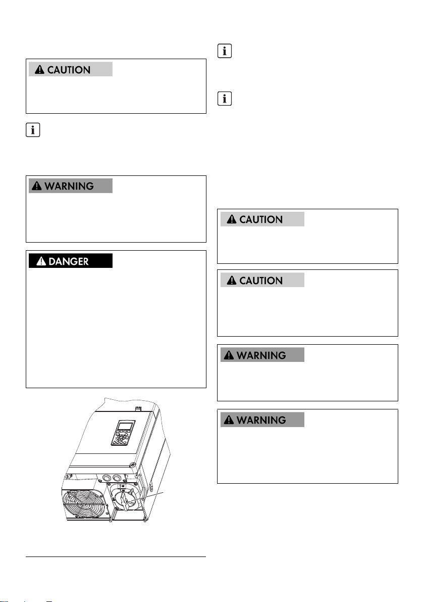
INFORMATION
The PV load-break switch can be secured in the "Off"
position using a padlock.
INFORMATION
Only for SHP 75-10:
The inverter is not intended to be used in living areas
and cannot provide protection of radio reception
against interference signals in such environments.
In accordance with EN55011:2016, the inverter
must only be operated at operation locations where
the distance between the inverter and
radio-communication installations is greater than
30 m and an own power transformer is used.
DC voltages up to 1000 V are present in a PV system
even when the inverter is disconnected from the utility grid.
Faults or inappropriate use may lead to electric arcing.
MAINTENANCE AND MODIFICATION
Only authorized personnel are permitted to repair or
modify the inverter. To ensure personal safety, use only
original spare parts available from the supplier.
INSTALLER
Input and output circuits are isolated from the enclosure.
System grounding is the responsibility of the installer.
RISK OF ELECTRIC SHOCK
This manual is intended for use by qualified personnel
only. To reduce the risk of electric shock, do not perform
any maintenance work other than that specified in the
manual unless you are qualified to do so.
Figure1: PV load-break switch
A PV load-break switch
14 SHP75-10-STP60-10-IA-xx-18 Installation Guide

SMA Solar Technology AG
Danger due to ground fault on DC side during
operation
Due to the transform erless topology of the product, the
occurrence of ground faults on DC side during operation
can lead to irreparable damage. Da mag es t o th e pr odu ct
due to a faulty or damaged DC installation are not
covered by warranty. The product is equipped with a
protective device that checks whether a ground fault is
present during the starting sequence. The product is not
protected during operation.
• Ensure th at the D C installation is ca rried out co rrec tly
and no ground fault occurs during operation.
The inverter is not equipped with a transformer and is
intended to be installed with an ungrounded (floating) PV
array.
Input and output circuits are isolated from the enclosure.
System grounding is the responsibility of the installer.
All persons responsible for the installation and
maintenance of inverters must be:
• Trained and authorized in general safety rules for
work on electric equipment.
• Familiar with local requirements, rules and
regulations for the installation.
The inverter does not provide overcurrent protection. This
must be provided by the installer. See table 5.8
The temperature of the cooling elements and components
in the inverter can exceed 70°C. There is a risk of burns.
The inverter is to be installed in such way that hot
components cannot be touched.
Damage to the product due to outgassing of
sealants
Sealants such as silicone, polyurethane foam or sealing
foam can outgas. Outgassing of sealants can damage the
product and impair its functionality.
• Do not use any sealants for sealing.
• Only use the provided material for sealing.
INFORMATION
The symbol for grounding conductors used in this
manual is identified in figure 2.18.
An ill ust rat ion of the DC d isc onn ect or c an be f oun d in
Section 3.2.2, page 32.
INFORMATION
For information about the operating temperature
range, see Section 5.3, page 44.
INFORMATION
This manual contains information about field wiring
connections and torque specifications. See Section
5.4, page 45.
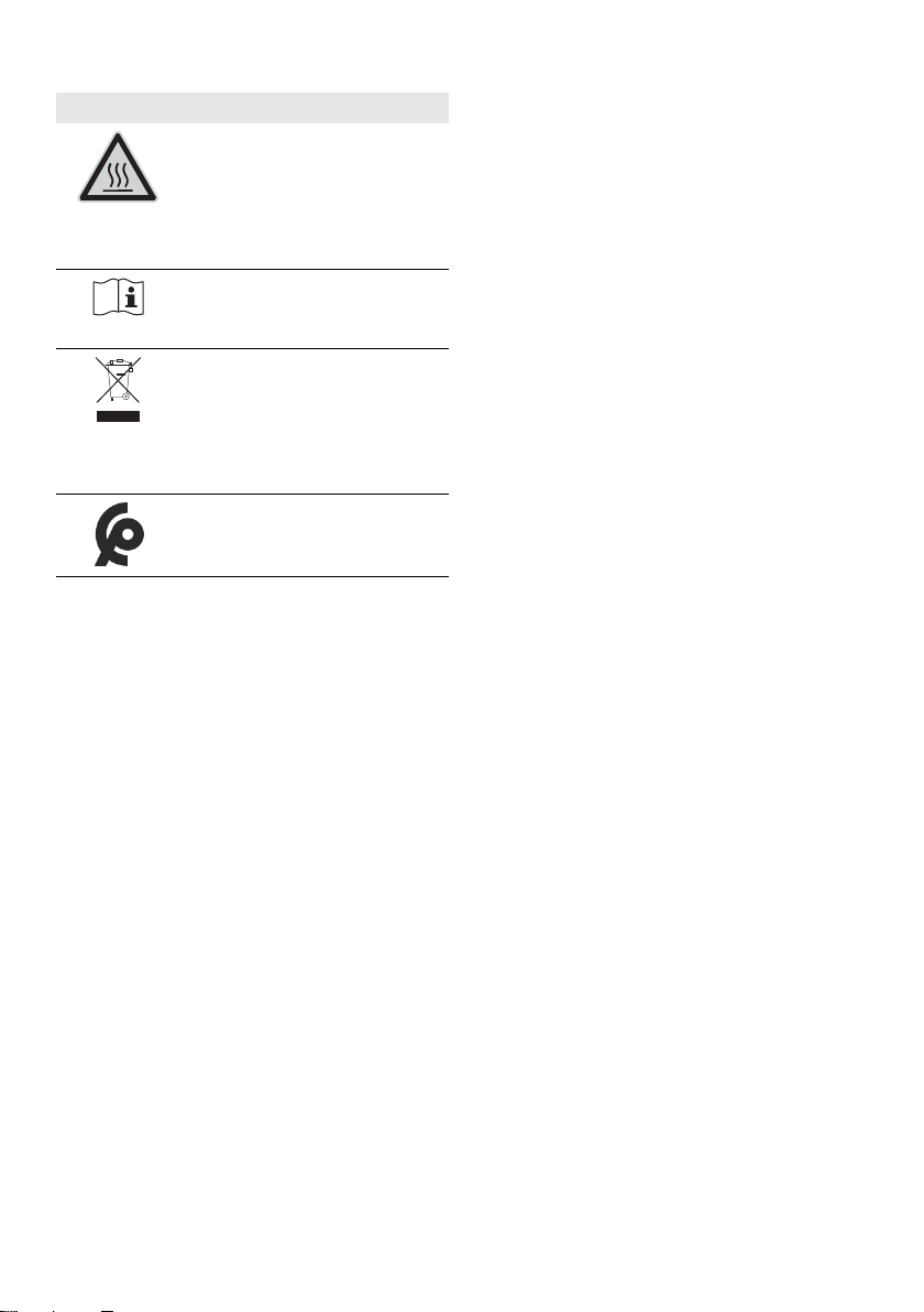
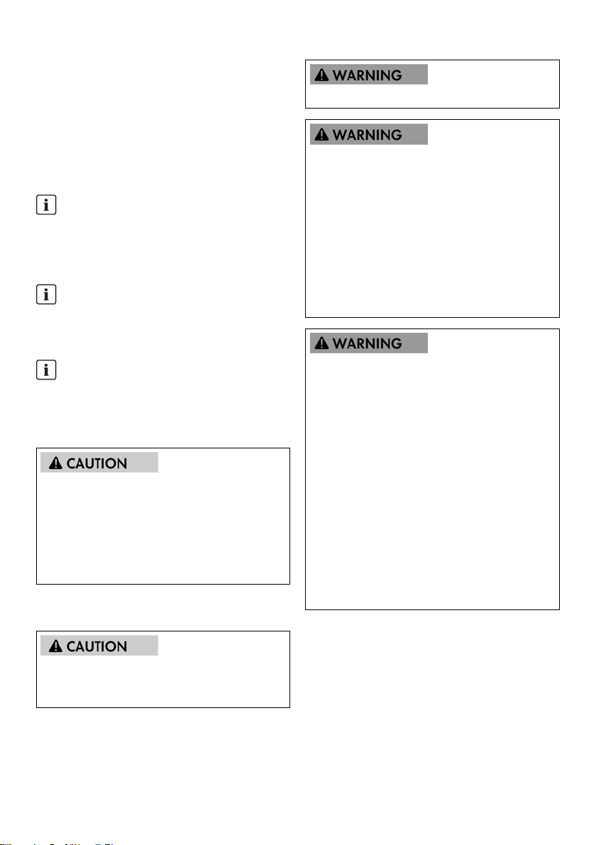
Symbols on the inverter
Symbol Explanation
Danger to life due to electric shock
The product operates at high voltages.
All work on the product must be
carried out by qualified persons only.
Danger
This symbol indicates that the inverter
must be additionally grounded if
additional grounding or equipotential
bonding is required at the installation
site.
Danger to life due to high voltages in
the inverter; observe waiting time.
High voltages that can cause lethal
electric shocks are present in the live
components of the inverter.
Prior to performing any work on the
inverter, disconnect it from all voltage
sources as described in this document.
Installation Guide SHP75-10-STP60-10-IA-xx-18 15
1 Introduction SMA Solar Technology AG
Symbol Explanation
Risk of burns due to hot surfaces
The product can get hot during
operation. Avoid contact during
operation. Allow the product to cool
down sufficiently before carrying out
any work.
Observe the documentation
Observe all documentation supplied
with the product.
WEEE designation
Do not dispose of the product together
with the household waste but in
accordance with the disposal
regulations for electronic waste
applicable at the installation site.
The product complies with the
Moroccan safety and EMC
requirements for electrical products.
Compliance
Further information can be found in the download area of
www.SMA-Solar.com (see also Section 5, page 41).
1 Introduction
The inverter is only designed for operation in grid-connected
PV systems. The inverter converts direct current from PV
modules into grid-compliant three-phase alternating current.
For operation, the inverter must be connected to a utility grid
and with a sufficient number of PV modules. The inverter is
not suitable for other applications (such as operation with
batteries or wind turbine systems).
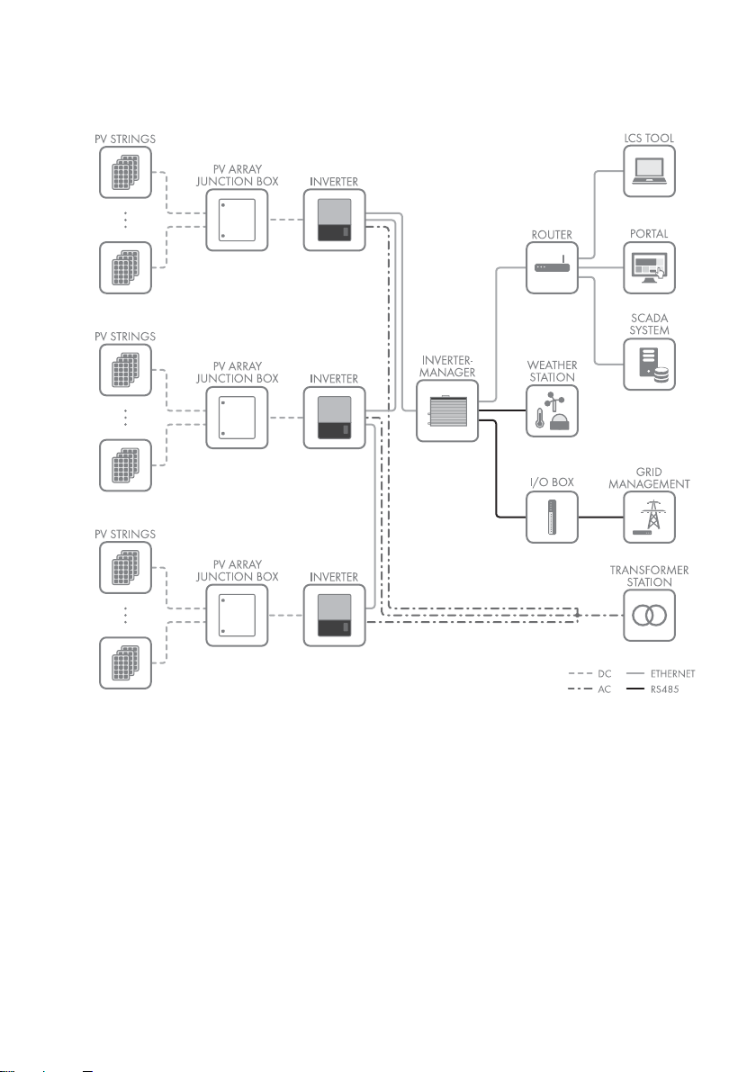
The PV system consists of four main components:
• Inverter
• PV array junction box
The PV array junction box enables the bundling of the
necessary number of PV strings for the inverter. Each
inverter requires a PV array junction box.
• SMA Inverter Manager
The SMA Inverter Manager is always required for the
operation of the inverter. Up to 42 inverters can be
connection to each SMA Inverter Manager. The
SMA Inverter Manager handles all communication of
the inverters. It serves as central interface for data
acquisition systems, upload to cloud services and
power-plant control.
• Local commissioning and service tool (LCS-Tool)
The LCS-Tool is required for the commissioning and
servicing of the inverter via the SMA Inverter Manager.
The LCS-Tool is the primary user interface for the PV
system.
16 SHP75-10-STP60-10-IA-xx-18 Installation Guide
SMA Solar Technology AG 1 Introduction
1.1 System Overview
Figure 1.1 System overview
1.2 Purpose of This Manual
The manual contains information on the installation and
commissioning of the inverter.
The following additional materials are available:
• Qu ick ref ere nce gui de f or t he i nst all ati on o f th e in ver ter
- information necessary for commissioning and for
establishing communication.
• Installation manual for the SMA Inverter Manager and
the I/O Box - information necessary for commissioning
and for establishing communication.
Installation Guide SHP75-10-STP60-10-IA-xx-18 17
• Service manual for replacing the fan – for information
required to replace a fan.
• Service manual for replacing the SPDs – contains
information required to replace surge protection
devices.
These documents are available in the download area at
www.SMA-Solar.com. You can also request these from the
supplier of the inverter.
1 Introduction SMA Solar Technology AG
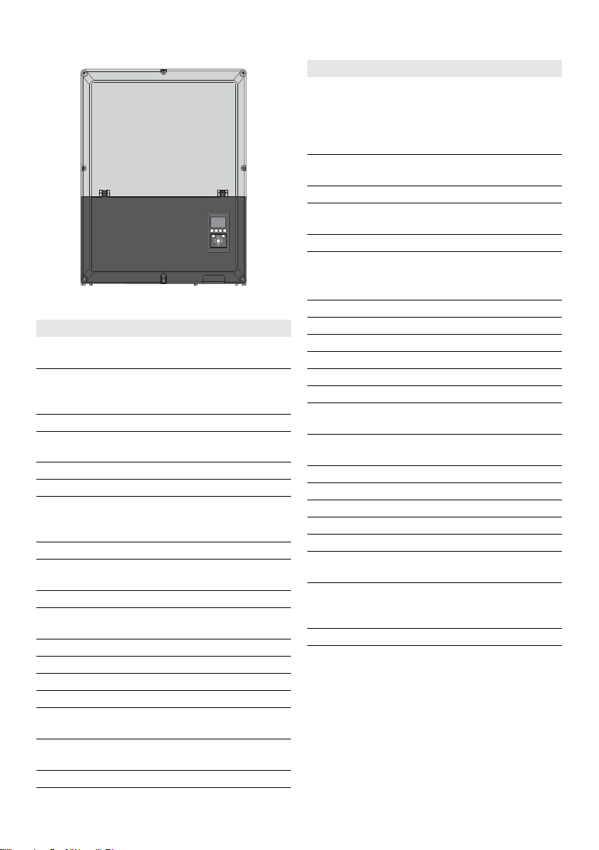
F1 F3 F4F2
OK
Home
Back
Alarm
On
Abbreviation Description
PCC Point of Common Coupling - point of
interconnection
The point on the public electricity network
to whi ch o the r cu sto mer s ar e, o r co uld be,
connected.
Grounding
Protective grounding
conductor
PELV Protected Extra-Low Voltage
PLA Power Level Adjustment = Output power
limitation
P
nom
Power [W], Nominal active power
POC Connection point
The point at which the PV system is
connected to the public utility grid.
Figure 1.2 Front view of the inverter
Abbreviation Description
cat5e Category 5 twisted pair cable (enhanced)
for data transmission
DHCP Dynamic Host Configuration Protocol –
enables automatic assignment of the
network address via the DHCP server
DSL Digital Subscriber Line
EMC
Electromagnetic compatibility directive
(directive)
ESD Electrostatic discharge
FRT Fault Ride Through
GSM Global System for Mobile
Communications (standard for digital
cellular mobile network)
HDD Hard Disk Drive
IEC International Electrotechnical Commission
– international standards organization
IT Isolated Terra
LCS Local commissioning and service tool
(LCS-Tool)
LED Light-Emitting Diode
P
STC
PV Photovoltaic, photovoltaic cells
RCD Residual-current device
RCMU Residual Current Monitoring Unit
R
ISO
ROCOF Rate of Change of Frequency
Q Q is the symbol for reactive power and is
S S is the symbol for apparent power and is
STC Standard Test Conditions
SW Software
THD Total Harmonic Distortion
TN-S Terra Neutral - Separate. AC Network
TN-C Terra Neutral - Combined. AC Network
TN-C-S Terra Neutral - Combined - Separate. AC
TT AC grid with separation between
DNO Distribution grid operator
Power [W], Standard Test Conditions
Insulation resistance
measured in reactive volt-amperes (VAr).
measured in volt-amperes (VA).
Network
operational ground of the generator and
ground of the load system
LVD (Directive) Low-voltage directive
MCB Miniature circuit breaker
MPP Maximum Power Point
MPPT Maximum Power Point Tracking
determines the point of optimum PV power
P P is the symbol for active power and is
measured in Watts (W).
PCB Printed circuit board
18 SHP75-10-STP60-10-IA-xx-18 Installation Guide

SMA Solar Technology AG 1 Introduction
1.3 Unpacking
Check the scope of delivery of each product for
completeness and any externally visible damage.
Contact your distributor if the scope of delivery is
incomplete or damaged.
The delivery may contain parts
that are not required for the installation.
Contents:
•Inverter
•Wall mounting bracket
• Accessories bag containing:
– 6 wall plugs 8 x 50 mm
– 6 mounting screws 6 x 60 mm
– 1 M25 cable gland with sealing grommet for
Ethernet cables
– 1 grounding bolt M6 x 12 mm
• Installation manual
• Quick reference guide for installation
1.4 Inverter Type Label
The type label uniquely identifies the inverter. You will
require the information on the type label to use the product
safely and when seeking customer support from the
SMA Service Line. You will find the following information on
the type label:
• Device type (Model)
• Serial number (Serial No.)
• Date of manufacture
• Device-specific characteristics
1.5 Installation Sequence
1. Pay special attention to the important safety
information at the beginning of this manual.
2. Mount the inverter according to Section 2.1, page 21,
Section 2.2, page 22, Section 2.3, page 23.
3. Open the inverter in accordance with Section
2.5, page 24.
4. Install the AC supply in accordance with Section
2.6, page 25.
5. Install Ethernet in accordance with Section
5.7, page 47.
6. Install the PV module in accordance with Section
2.9, page 28 using a PV array junction box.
7. Close the inverter in accordance with Section
2.5, page 24.
8. Turn on AC.
9. Finalize commissioning by using the Local
Commissioning and Service Tool (LCS-Tool). The tool is
available from the download area at
www.SMA-Solar.com. The hardware requirements for
the LCS-Tool are:
– PC with Windows
–1 GB HDD
– 2 GB RAM
The LCS-Tool must be installed on a local PC drive.
The PC mus t be con nected to the s ystem network of t he
SMA Inverter Manager. See Section 3.2.1, page 32
for configuring via the LCS-Tool.
10. Switch on the PV system via the PV load-break switch.
11. Verify the installation by:
– Inverter display: LED "On" is permanently green.
– LCS-Tool: In the inverter view, the status is
"On grid".
12. The inverter is in operation now.
TM
7 and later
Installation Guide SHP75-10-STP60-10-IA-xx-18 19
1 Introduction SMA Solar Technology AG
B
C
D
E
F
G
H
A
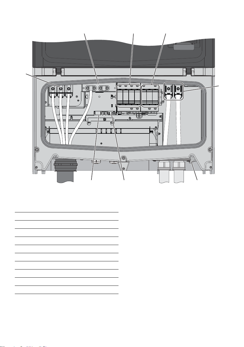
Figure 1.3 Overview of the installation area
PELV (safe to touch)
B Device grounding
G Ethernet interface x 2
H RS485 interface (not in use)
Live parts
AAC terminals
EPV terminals
Other
C AC overvoltage protection (SPDs)
D DC overvoltage protection (SPDs)
F PV load-break switch
Table 1.2 Overview of the installation area
20 SHP75-10-STP60-10-IA-xx-18 Installation Guide
SMA Solar Technology AG 2 Installation
2Installation
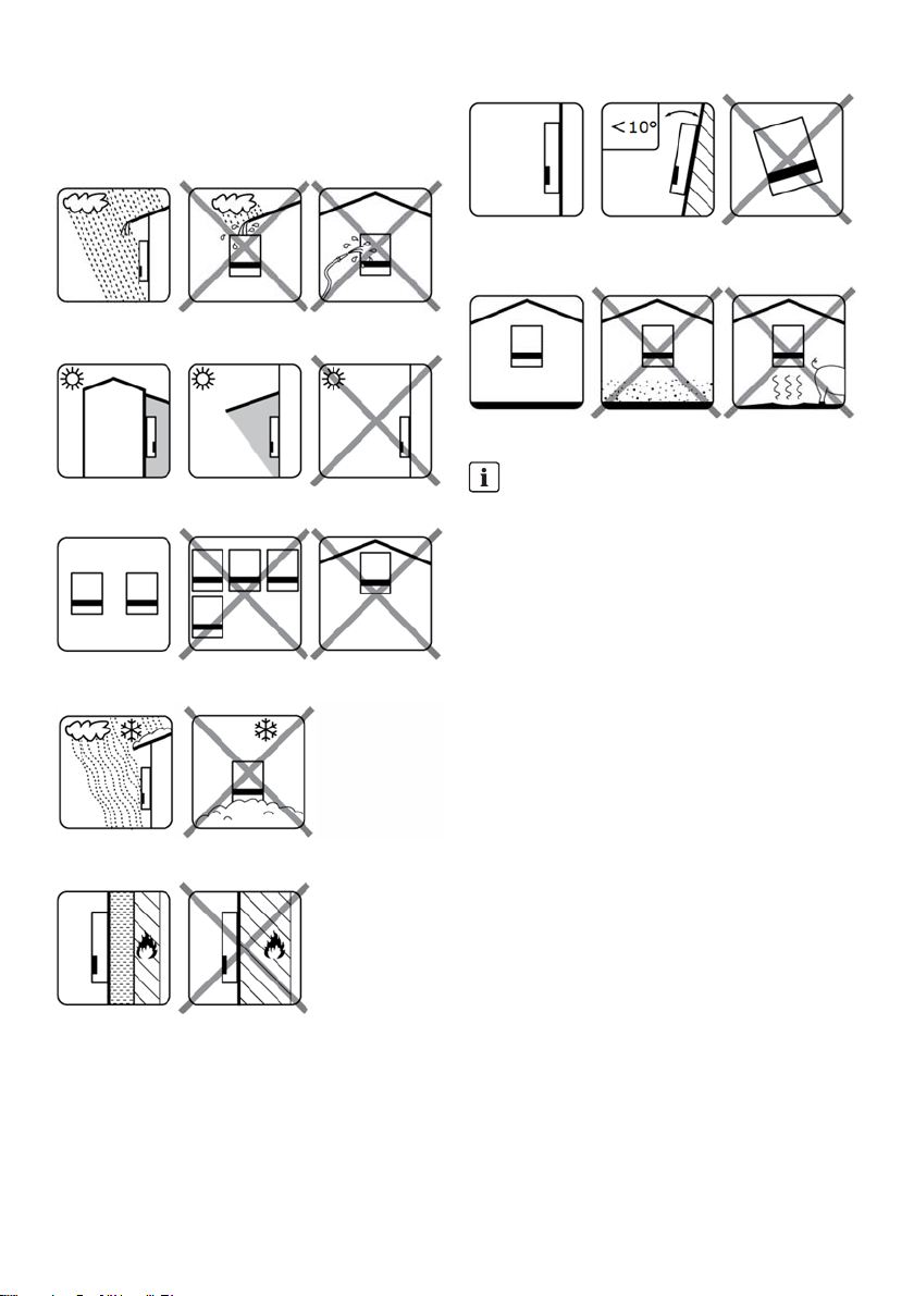
2.1 Environment and Clearances
Figure 2.6 Mount upright on vertical surface. A backward tilt of ten
degrees is allowed.
Figure 2.1 Avoid constant contact with water
Figure 2.7 Avoid dust and ammonia gases
INFORMATION
Figure 2.2 Avoid direct solar irradiation
Figure 2.3 Ensure adequate air flow
When selecting the installation site, ensure that the
product and warning messages on the inverter are
visible at all times. For details, refer to Section
5, page 41.
Figure 2.4 Ensure adequate air flow
Figure 2.5 Mount on non-flammable surface
Installation Guide SHP75-10-STP60-10-IA-xx-18 21
2 Installation SMA Solar Technology AG
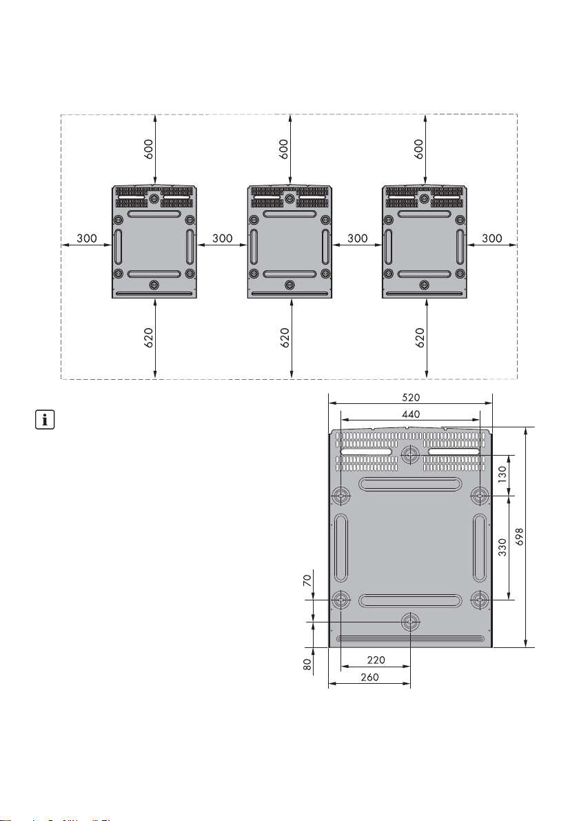
2.2 Mounting the Wall Mounting Bracket
Figure 2.8 Safety clearances in mm
INFORMATION
The safety clearances to other objects must be
maintained to ensure sufficient air circulation (see
figure 2.8).
Figure 2.9 Dimensions of wall mounting bracket in mm
22 SHP75-10-STP60-10-IA-xx-18 Installation Guide
SMA Solar Technology AG 2 Installation
INFORMATION
Use of the wall mounting bracket delivered with the
inverter is mandatory. Warranty claims will expire if
the inverter is operated without the wall mounting
bracket. It is strongly recommended to use all six
mounting holes (see figure 2.10).
Mounting of the wall mounting bracket:
• Mount the wall mounting bracket in the designated
area.
• Use screws and wall plugs that can safely carry the
weight of the inverter.
• Ensure that the wall mounting bracket is correctly
aligned.
• When installing one or several inverters, observe the
safety clearances to ensure sufficient airflow.
Clearances are specified in figure 2.8 and on the wall
mounting bracket label.
• Mounting multiple inverters side by side in a single row
is recommended. Contact the supplier for guidelines
when mounting inverters in more than one row.
• Ensure adequate clearance at the front, for safe
installation and service access to the inverter.
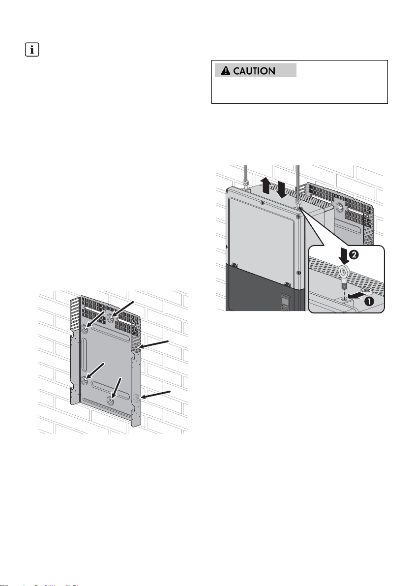
2.3 Mounting the Inverter
When handling the inverter observe the local health and
safety regulations.
Procedure:
1. Attach M12 lifting bolts and matching nuts to the
inverter (not included in the scope of delivery).
2. Lift the inverter.
Figure 2.11 Attaching the lifting bolts and lifting the inverter
3. Locate the slots on the side of the wall mounting
bracket.
4. On the inverter, position the side screws against the
wall mounting bracket slots. Push the inverter so the
side screws slide into the two lower slots and the two
upper slots.
Figure 2.10 Mounting of the wall mounting bracket
Installation Guide SHP75-10-STP60-10-IA-xx-18 23
2 Installation SMA Solar Technology AG
2.5 Access to the Installation Area
Before working on the inverter, disconnect it from the utility
grid by means of the AC breaker and switch off PV using
the integrated PV load-break switch (DC load-break
switch). Ensure that the inverter cannot be unintentionally
reconnected. Use a voltage detector to ensure that the
unit is disconnected and voltage free. The inverter can still
be charged with very high voltage at hazardous levels
even when it is disconnected from utility grid and PV
modules. Wait at least five minutes after disconnection
from the utility grid and PV modules before proceeding.
Observe ESD safety regulations. Discharge any
electrostatic charge by touching the grounded enclosure,
Figure 2.12 Hooking the inverter into the wall mounting bracket
5. Check that the four side screws sit securely in the wall
mounting bracket slots.
6. Release the inverter.
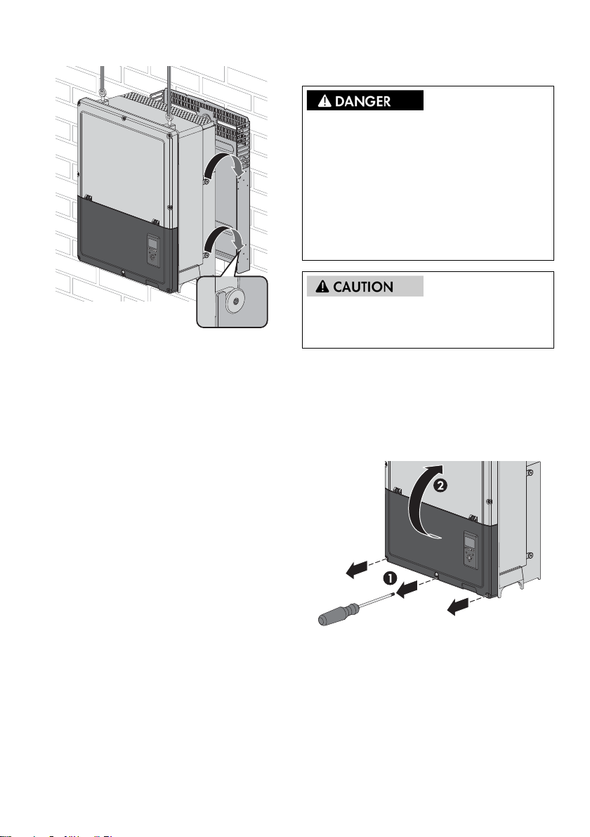
2.4 Disassembling the Inverter
Procedure:
1. Disassemble the inverter in the reverse mounting order.
2. Lift and slide the inverter out of the wall mounting
bracket slots.
3. Lift the inverter off the wall mounting bracket.
before handling any electronic component.
Procedure:
1. To open the cover, loosen the three lower front screws
using a TX 30 screwdriver. The screws are captive
screws and cannot fall out.
2. Raise the cover by 180 degrees. A magnet enables the
cover to stay open.
Figure 2.13 Loosen front screws and lift the cover
3. To close the cover, lower it into place and fasten the
three front screws.
24 SHP75-10-STP60-10-IA-xx-18 Installation Guide
SMA Solar Technology AG 2 Installation
2.6 AC Grid Connection
These instructions for AC grid connection are for qualified
pe rso nne l on ly. To r edu ce t he r isk of e lec tri c sh ock , do not
perform any maintenance work other than that specified
in the manual unless you are qualified to do so.
For fuse and RCD information, refer to Section
5, page 41. AC fuse rating must not exceed the ampacity
of the conductors used.
IMI Detection
The inverter has a built-in IMI/RCMU (Insulation Monitoring
Interrup ter / Resi dual Curr ent Mon itorin g Unit). T he invert er
acts on residual DC current and a sudden change in the
ground fault current. This functionality is activated during
normal operation.
Insulation Resistance Detection
Th e in ver ter ha s a b uil t-i n in sul ati on res ist anc e de tec tio n. T he
insulation resistance detector performs a measurement of
the connected PV system resistance to ground before the
inverter connects to the grid. If the resistance is below the
gr id c ode set val ue, the inv erter wil l wa it a nd r e-m eas ure the
resistance after a short while. When the resistance is above
the grid code set value, the inverter performs a self-test and
connects to the grid.
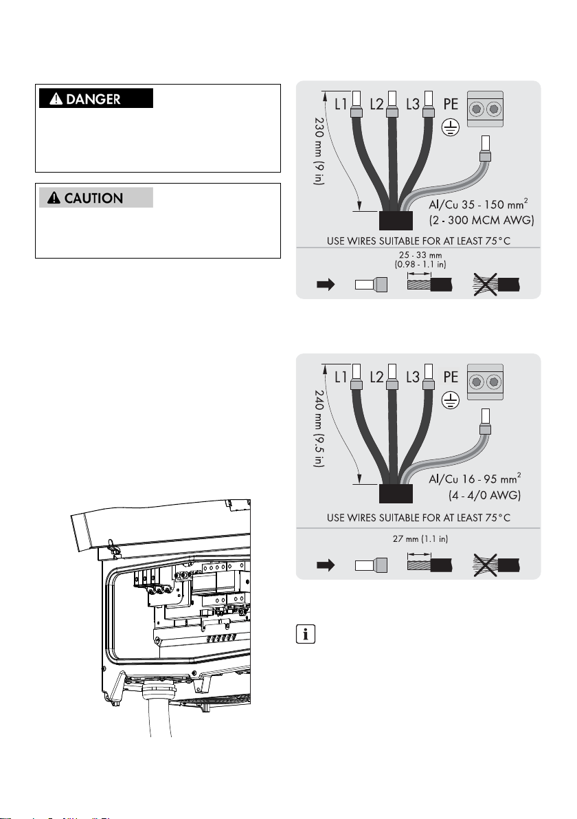
Cable requirements SHP 75-10
Figure 2.15 AC cable SHP 75-10
Cable requirements STP 60-10
Figure 2.16 AC cable SHP 60-10
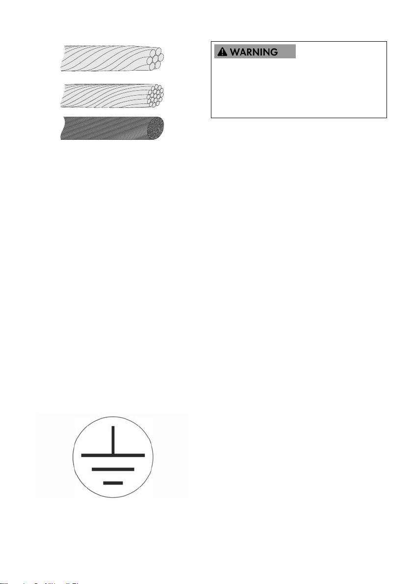
INFORMATION
Cables with multi-strand, fine-strand or extra
fine-strand conductors can be used for AC
connection (see figure 2.15 and 2.16). The cables
must be suitable for a temperature of at least 75°C.
When using fine-strand or extra fine-strand
conductors, bootlace ferrules must be used for the
Figure 2.14 Installation area
Installation Guide SHP75-10-STP60-10-IA-xx-18 25
connection.
2 Installation SMA Solar Technology AG
LEAKAGE CURRENT HAZARD
Insufficient grounding of the inverter can lead to serious
injuries or lethal injuries.
• Ensure the correct grounding of the devices by a
certified electrical installer.
Figure 2.17 Cables with different conductors (from top to bottom):
multi-strand, fine-strand and extra fine-strand
The inverter may only be connected to a three-phase utility
grid.
Strip off the insulation of all four AC cable conductors. The
protective conductor (PE) must be longer than the grid wires.
1. Verify that the nominal voltage of the inverter matches
the grid voltage.
2. Ensure that the main circuit breaker is released, and
take precautions to prevent reconnection.
3. Open the front cover.
4. Insert the cable through the AC cable gland to the
terminal block.
5. Connect the three grid wires (L1, L2, L3) and the
grounding conductor (PE) to the terminal block with the
respective markings. The grounding conductor is
marked with the symbol shown in figure 2.17.
6. Optional: Make an extra PE connection at the
secondary PE grounding points using the external
device grounding bolt delivered with the inverter. See
figure 5.2.
7. All conductors must be properly attached with the
correct tool (screwdriver bit, length min. 50 mm) and
correct torque, see Section 5.4, page 45.
Figure 2.18 Grounding conductor symbol
26 SHP75-10-STP60-10-IA-xx-18 Installation Guide
SMA Solar Technology AG 2 Installation
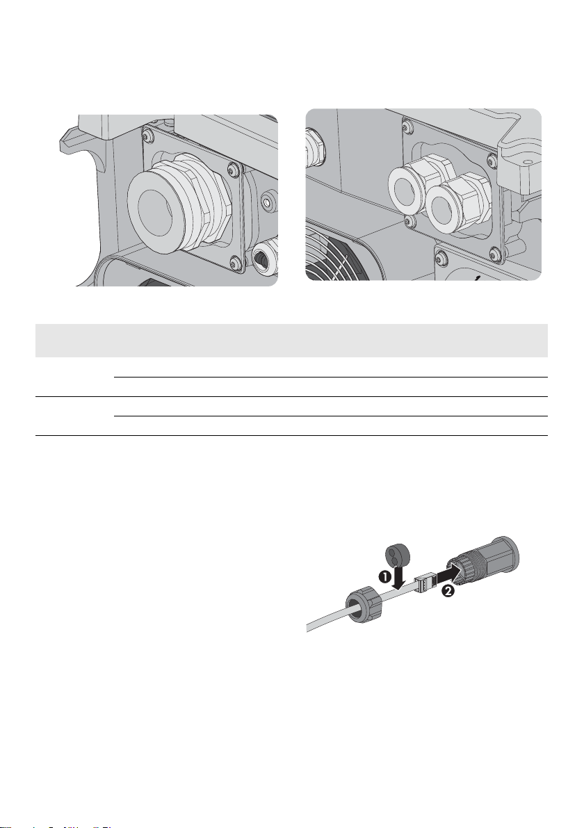
2.7 Enclosure opening
The mounting brackets for the cable glands are already
pre-mounted.
Figure 2.19 AC cable gland
Terminal Range
1)
Figure 2.20 DC cable gland
Line material Cable sheath diameter with
supplied cable gland
SHP 75-10 AC+PE 35 to 150 mm² Al/Cu 46 to 53 mm
PV 35 to 150 mm² Al/Cu 18 to 25 mm
STP 60-10 AC+PE 16 to 95 mm² Al/Cu 37 to 44 mm
PV 16 to 95 mm² Al/Cu 14 to 21 mm
Table 2.1 Suitable conductor sizes
1)
Always observe the ampacity of cables used.
2.8 Ethernet Connections
When used outdoors, make sure to use a suitable cable (see
Section 5.6 “Technical Data of the Communication
Interface”, page 47). If the cable is very stiff, an
intermediate terminal should be used to achieve greater
flexibility of the cable before it is connected to the inverter.
For some cables, it may be sufficient to remove the outer
hard sheath from the part of the cable that is inserted into
the inverter enclosure. In this way, the RJ45 Ethernet
connectors mounted on the printed circuit boards are
protected against excessive stress, which could lead to
damages or problems with the connection.
Procedure:
1. Do not remove the RJ45 connector on the Ethernet
cable.
2. Run the cables through the base of the inverter via
cable glands. See figure 2.20.
3. Cut slice in rubber grommet. Place the grommet in the
gland to ensure proper seal.
4. Plug into the Ethernet connector.
Figure 2.21 Run cables through cable glands
Installation Guide SHP75-10-STP60-10-IA-xx-18 27
2 Installation SMA Solar Technology AG
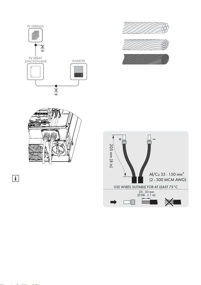
2.9 PV Connection
2.9.1 External PV Array Junction Boxes
PV str ing s mu st b e co nne cte d to the DC i npu t vi a an ext ern al
PV array junction box. The PV array junction box connects
the PV strings of the PV array and protects the individual
strings against overcurrent with appropriate fuse protection.
INFORMATION
The same number and type of modules must be
connected to all PV strings connected to the PV array
junction box. In addition, all connected modules must
have the same orientation.
INFORMATION
Observe correct fuse rating. Consult the module
manufacturer's manuals for information on correct
string fuse rating.
INFORMATION
Use a suitable voltage detector that can measure up
to 1000 V DC. Verify the polarity and maximum
voltage of the PV arrays by measuring the PV
open-circuit voltage.
The inverter is protected against short-term reverse
polarity. Not correcting reverse polarity results in
irreparable defects of the inverter and will void the
warranty.
• Make sure that the cables are properly connected to
the inverter so that the inverter can feed in DC input
voltage.
The combined power from the PV array junction box must
be connected to the DC input of the inverter.
Do NOT connect PV to ground!
Danger due to ground fault on DC side during
operation
Due to the transform erless topology of the product, the
occurrence of ground faults on DC side during operation
can lead to irreparable damage. Damages to the product
due to a faulty or damaged DC installation are not
covered by warranty. The product is equipped with a
protective device that checks whether a ground fault is
present during the starting sequence. The product is not
protected during operation.
• Ensure that the D C insta llation i s carri ed out cor rectly
and no ground fault occurs during operation.
Danger to life due to fire or explosion
In rare cases, an explosive gas mixture can be generated
inside the product in the event of an error. In this state,
switching operations can cause a fire or explosion. Death
or lethal injuries due to fire or flying debris can result.
• In case of error, only carry out corrective measures
specified by SMA Solar Technology AG (for
corrective measures see Section 4.1, page 34).
If no corrective measures are specified, do not
perform any actions on the product. Contact the
service.
• Disconnect the PV array from the product via an
external disconnection device. Do not operate the
DC load-break switch on the product
• Ensure that unauthorized persons have no access to
the product.
• Disconnect AC circuit breaker and secure against
reconnection.
PV array is floating, with both the (+) and (-) conductors
connected to the PV inputs of the inverter. Neither
conductor is connected to ground.
The DC power can be disconnected with the
inverter-integrated DC load-break switch.
28 SHP75-10-STP60-10-IA-xx-18 Installation Guide
SMA Solar Technology AG 2 Installation
Figure 2.22 Do not connect PV to ground
Figure 2.23: DC connection area
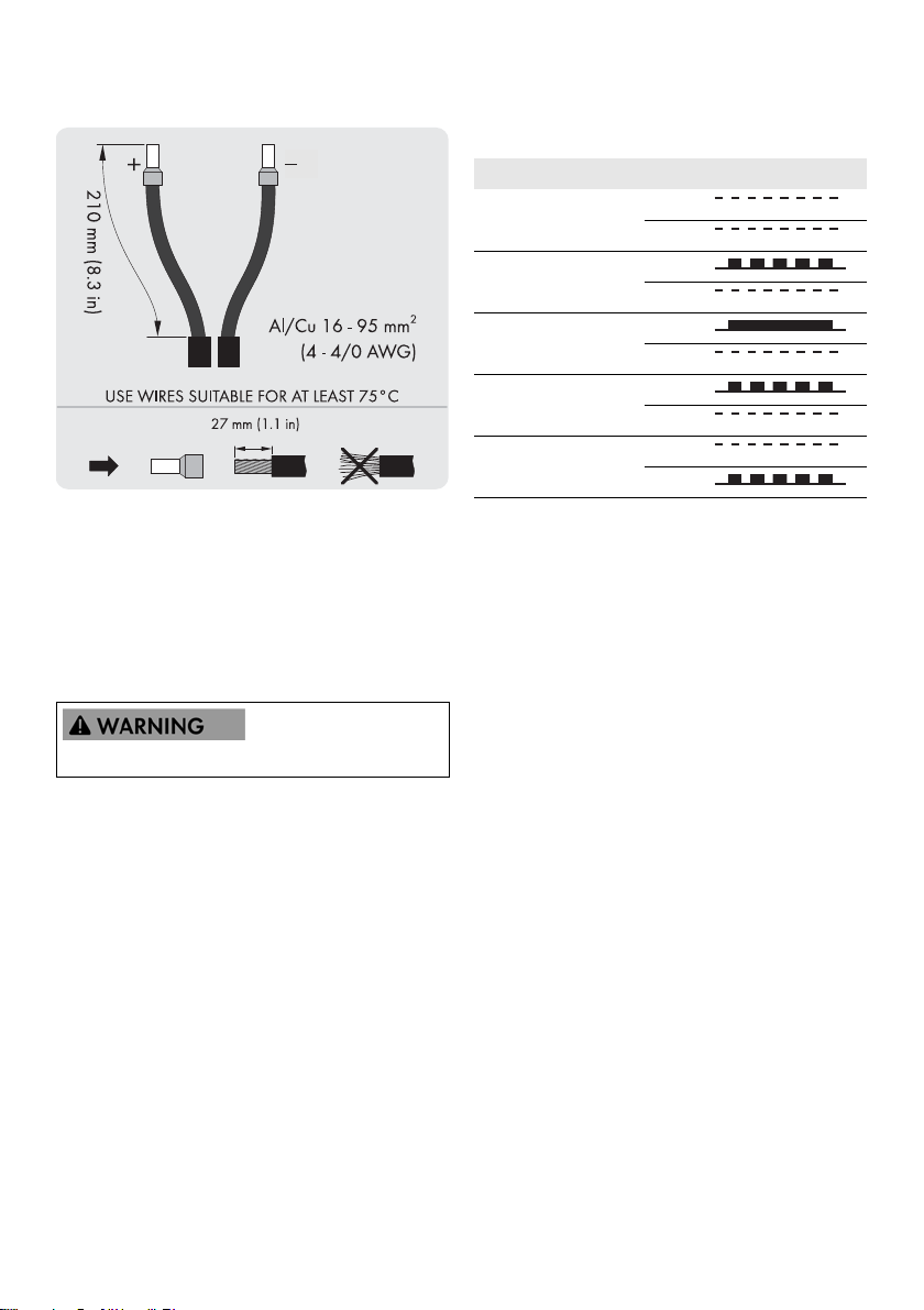
INFORMATION
Cables with multi-strand, fine-strand or extra
fine-strand conductors can be used for AC
connection (see figure 2.23). The cables must be
suitable for a temperature of at least 75°C.
When using fine-strand or extra fine-strand
conductors, bootlace ferrules must be used for the
connection.
Figure 2.24 Cables with different conductors (from top to bottom):
multi-strand, fine-strand and extra fine-strand
1. Switch the PV l oad-br eak swi tch on t he invert er to "O ff"
and, if available, also on the PV array junction box.
2. Connect the PV cables from the PV array junction box
to the inverter. Ensure the correct polarity when doing
so.
3. All conductors must be properly attached with the
correct tool (screwdriver bit, length min. 50 mm) and
correct torque, see Section 5.4, page 45.
Cable requirements SHP 75-10
Figure 2.25 DC label SHP 75-10
Installation Guide SHP75-10-STP60-10-IA-xx-18 29
3 Initial Setup and Start SMA Solar Technology AG
Cable requirements STP 60-10
Figure 2.25 DC label STP 60-10
Protection class of PV modules
The inverter must only be operated with PV modules of
protection class II, compliant with IEC 61730, application
class A.
Only connect PV modules to the inverter. Other energy
sources are not allowed.
3.1.1 Operating Modes
The inverter has five operation modes, indicated by LEDs.
Status LEDs LEDs
Off grid Green
Red
Connecting Green
Red
On grid Green
Red
Internal inverter event Green
Red
Fail safe Green
Red
Table 3.1 Operating modes
Off grid (LEDs off)
#0-51
If no electric current has been fed into the AC grid for more
th an ap pro x. ten minu tes, t he inv erter disco nnect s itse lf fro m
the utility grid and shuts down. User and communication
interfaces remain powered for communication purposes.
PV modules generate a voltage when exposed to light.
2.10 Closing
1. Close the cover of the inverter installation area. Fasten
the three front screws (see Section 5.4, page 45).
2. Turn on AC power.
3 Initial Setup and Start
3.1 User Interface
The user interface comprises:
• Local display, for all inverter variants. The local display
shows status information of the inverter. It is not
possible to set up or configure the inverter via the
display. The "#" in the display explains the operation
modes.
• Local commissioning and service tool (LCS-Tool). The
LCS-Tool can be used for configuring one or more
inverters.
30 SHP75-10-STP60-10-IA-xx-18 Installation Guide
 Loading...