

Page 1
EN
System Monitoring
SUNNY SENSORBOX
Installation Guide
Sensorbox-IEN100914 | 98-0001114 | Version 1.4
Page 2

SMA Solar Technology AG
2 Sensorbox-IEN100914 Installation Guide
Page 3

SMA Solar Technology AG Table of Contents
Table of Contents
1 Notes on this Manual. . . . . . . . . . . . . . . . . . . . . . . . . . . . . . 7
1.1 Validity . . . . . . . . . . . . . . . . . . . . . . . . . . . . . . . . . . . . . . . . . . . . 7
1.2 Target Group . . . . . . . . . . . . . . . . . . . . . . . . . . . . . . . . . . . . . . . 7
1.3 Additional Information . . . . . . . . . . . . . . . . . . . . . . . . . . . . . . . . 7
1.4 Symbols Used . . . . . . . . . . . . . . . . . . . . . . . . . . . . . . . . . . . . . . . 8
2 The Sunny SensorBox . . . . . . . . . . . . . . . . . . . . . . . . . . . . . 9
3 Safety . . . . . . . . . . . . . . . . . . . . . . . . . . . . . . . . . . . . . . . . . 10
3.1 Appropriate Usage. . . . . . . . . . . . . . . . . . . . . . . . . . . . . . . . . . 10
3.2 Safety Precautions. . . . . . . . . . . . . . . . . . . . . . . . . . . . . . . . . . . 11
4 Unpacking. . . . . . . . . . . . . . . . . . . . . . . . . . . . . . . . . . . . . . 12
4.1 Packing List . . . . . . . . . . . . . . . . . . . . . . . . . . . . . . . . . . . . . . . . 12
4.2 Identifying the Product . . . . . . . . . . . . . . . . . . . . . . . . . . . . . . . 14
4.2.1 Type Label. . . . . . . . . . . . . . . . . . . . . . . . . . . . . . . . . . . . . . . . . . . . . . . . . . . 14
4.2.2 Firmware Version . . . . . . . . . . . . . . . . . . . . . . . . . . . . . . . . . . . . . . . . . . . . . 14
5 Device Overview . . . . . . . . . . . . . . . . . . . . . . . . . . . . . . . . 15
5.1 Device Overview of the Sunny SensorBox . . . . . . . . . . . . . . . . 15
5.2 Device Overview of the RS485 Power Injector . . . . . . . . . . . . 16
5.3 Device Overview of the SMA Power Injector with Bluetooth. . 17
5.3.1 LED for the Power Supply . . . . . . . . . . . . . . . . . . . . . . . . . . . . . . . . . . . . . . . 17
5.3.2 LEDs Indicating Connection Quality (Bluetooth LEDs). . . . . . . . . . . . . . . . . . 18
5.3.3 LED for Data Communication . . . . . . . . . . . . . . . . . . . . . . . . . . . . . . . . . . . . 19
6 Mounting the Device . . . . . . . . . . . . . . . . . . . . . . . . . . . . . 20
6.1 Sunny SensorBox . . . . . . . . . . . . . . . . . . . . . . . . . . . . . . . . . . . 20
6.1.1 Requirements for the Mounting Location. . . . . . . . . . . . . . . . . . . . . . . . . . . . 20
6.1.2 Mounting the Sunny SensorBox on a Mounting Rail . . . . . . . . . . . . . . . . . . 21
6.1.3 Mounting the Sunny SensorBox on Rafters. . . . . . . . . . . . . . . . . . . . . . . . . . 23
Installation Guide Sensorbox-IEN100914 3
Page 4

Table of Contents SMA Solar Technology AG
6.2 Mounting the Temperature Sensor on the PV Module . . . . . . . 26
6.3 RS485 Power Injector. . . . . . . . . . . . . . . . . . . . . . . . . . . . . . . . 28
6.3.1 Requirements for the Mounting Location. . . . . . . . . . . . . . . . . . . . . . . . . . . . 28
6.3.2 Mounting the RS485 Power Injector on a Wall . . . . . . . . . . . . . . . . . . . . . . 28
6.4 SMA Power Injector with Bluetooth . . . . . . . . . . . . . . . . . . . . . 30
6.4.1 Requirements for the Mounting Location. . . . . . . . . . . . . . . . . . . . . . . . . . . . 30
6.4.2 Information on SMA Bluetooth . . . . . . . . . . . . . . . . . . . . . . . . . . . . . . . . . . 30
6.4.3 Determining the Mounting/Installation Location . . . . . . . . . . . . . . . . . . . . . . 31
6.4.4 Mounting the SMA Power Injector with Bluetooth on a Wall . . . . . . . . . . . . 33
6.4.5 Mounting the SMA Power Injector with Bluetooth on a Top Hat Rail . . . . . . 34
7 Startup. . . . . . . . . . . . . . . . . . . . . . . . . . . . . . . . . . . . . . . . . 36
7.1 Information on Starting up the Device . . . . . . . . . . . . . . . . . . . 36
7.2 Connecting the Module Temperature Sensor . . . . . . . . . . . . . . 36
7.3 Connecting the Anemometer . . . . . . . . . . . . . . . . . . . . . . . . . . 38
7.4 Connecting the Ambient Temperature Sensor. . . . . . . . . . . . . . 39
7.5 Startup via the RS485-Power Injector . . . . . . . . . . . . . . . . . . . . 40
7.5.1 Information on Starting up the Device. . . . . . . . . . . . . . . . . . . . . . . . . . . . . . 40
7.5.2 Connecting the RS485-Power Injector to an RS485 Bus Node . . . . . . . . . . 41
7.5.3 Connecting the RS485 Power Injector to the Sunny SensorBox . . . . . . . . . . 43
7.5.4 Connecting the Sunny SensorBox to another Sunny SensorBox . . . . . . . . . . 46
7.5.5 Connecting the Sunny SensorBox to an Additional RS485 Bus Node . . . . . 50
7.5.6 Connecting the RS485 Power Injector to the Power Supply. . . . . . . . . . . . . 52
7.6 Startup via the SMA Power Injector with Bluetooth . . . . . . . . . 53
7.6.1 Information on Starting up the Device. . . . . . . . . . . . . . . . . . . . . . . . . . . . . . 53
7.6.2 Grounding the Sunny SensorBox . . . . . . . . . . . . . . . . . . . . . . . . . . . . . . . . . 53
7.6.3
7.6.4 Connecting the SMA Power Injector with Bluetooth to the Power Supply . . 58
Connecting the Sunny SensorBox to the SMA Power Injector with
Bluetooth
. .55
8 Opening and Closing the Sunny SensorBox . . . . . . . . . . 61
8.1 Opening the Sunny SensorBox. . . . . . . . . . . . . . . . . . . . . . . . . 61
8.2 Closing the Sunny SensorBox . . . . . . . . . . . . . . . . . . . . . . . . . . 61
4 Sensorbox-IEN100914 Installation Guide
Page 5

SMA Solar Technology AG Table of Contents
9 Maintenance and Care . . . . . . . . . . . . . . . . . . . . . . . . . . . 62
9.1 Maintenance. . . . . . . . . . . . . . . . . . . . . . . . . . . . . . . . . . . . . . . 62
9.2 Terminating the RS485 Bus on the Sunny SensorBox. . . . . . . . 62
9.3 Connecting the Integrated Solar Radiation Sensor. . . . . . . . . . 63
9.4 Replacing the Gaskets of the Sunny SensorBox . . . . . . . . . . . . 63
9.5 Care . . . . . . . . . . . . . . . . . . . . . . . . . . . . . . . . . . . . . . . . . . . . . 64
10 Decommissioning . . . . . . . . . . . . . . . . . . . . . . . . . . . . . . . . 65
10.1 Dismantling the Sunny SensorBox. . . . . . . . . . . . . . . . . . . . . . . 65
10.2 Dismantling the RS485 Power Injector . . . . . . . . . . . . . . . . . . . 65
10.3 Dismantling the SMA Power Injector with Bluetooth . . . . . . . . 66
10.4 Dismantling the Sensors . . . . . . . . . . . . . . . . . . . . . . . . . . . . . . 66
10.5 Packaging the Sunny SensorBox and Sensors . . . . . . . . . . . . . 67
10.6 Disposing of the Sunny SensorBox and Sensors. . . . . . . . . . . . 67
11 Troubleshooting . . . . . . . . . . . . . . . . . . . . . . . . . . . . . . . . . 68
11.1 Sunny SensorBox . . . . . . . . . . . . . . . . . . . . . . . . . . . . . . . . . . . 68
11.2 RS485 Power Injector. . . . . . . . . . . . . . . . . . . . . . . . . . . . . . . . 69
11.3 SMA Power Injector with Bluetooth. . . . . . . . . . . . . . . . . . . . . 70
12 Parameters . . . . . . . . . . . . . . . . . . . . . . . . . . . . . . . . . . . . . 71
12.1 RS485 Power Injector. . . . . . . . . . . . . . . . . . . . . . . . . . . . . . . . 71
12.1.1 Display Values . . . . . . . . . . . . . . . . . . . . . . . . . . . . . . . . . . . . . . . . . . . . . . . 71
12.1.2 Configurable Parameters . . . . . . . . . . . . . . . . . . . . . . . . . . . . . . . . . . . . . . . 72
12.2 SMA Power Injector with Bluetooth. . . . . . . . . . . . . . . . . . . . . 73
12.2.1 Display Values . . . . . . . . . . . . . . . . . . . . . . . . . . . . . . . . . . . . . . . . . . . . . . . 73
12.2.2 Configurable Parameters . . . . . . . . . . . . . . . . . . . . . . . . . . . . . . . . . . . . . . . 73
13 Technical Data . . . . . . . . . . . . . . . . . . . . . . . . . . . . . . . . . . 74
13.1 Sunny SensorBox . . . . . . . . . . . . . . . . . . . . . . . . . . . . . . . . . . . 74
13.2 RS485 Power Injector. . . . . . . . . . . . . . . . . . . . . . . . . . . . . . . . 75
Installation Guide Sensorbox-IEN100914 5
Page 6

Table of Contents SMA Solar Technology AG
13.3 SMA Power Injector with Bluetooth. . . . . . . . . . . . . . . . . . . . . 76
13.4 Plug-in Power Supply . . . . . . . . . . . . . . . . . . . . . . . . . . . . . . . . 77
14 Accessories . . . . . . . . . . . . . . . . . . . . . . . . . . . . . . . . . . . . . 78
14.1 Mounting Plate . . . . . . . . . . . . . . . . . . . . . . . . . . . . . . . . . . . . . 78
14.2 Roof Bracket . . . . . . . . . . . . . . . . . . . . . . . . . . . . . . . . . . . . . . . 78
14.3 Gasket Set for Sunny SensorBox . . . . . . . . . . . . . . . . . . . . . . . 79
14.4 RS485 Power Injector. . . . . . . . . . . . . . . . . . . . . . . . . . . . . . . . 79
14.5 SMA Power Injector with Bluetooth. . . . . . . . . . . . . . . . . . . . . 80
14.6 Anemometer . . . . . . . . . . . . . . . . . . . . . . . . . . . . . . . . . . . . . . . 80
15 Contact . . . . . . . . . . . . . . . . . . . . . . . . . . . . . . . . . . . . . . . . 81
6 Sensorbox-IEN100914 Installation Guide
Page 7

SMA Solar Technology AG Notes on this Manual
1 Notes on this Manual
1.1 Validity
This manual applies to the SunnySensorBox with firmware version 1.51 or higher and hardware
version C1 or higher.
1.2 Target Group
This manual is intended for the installer.
1.3 Additional Information
Further information about SMA Bluetooth Wireless Technology can be found in the download section
at www.SMA.de/en.
Installation Guide Sensorbox-IEN100914 7
Page 8
Notes on this Manual SMA Solar Technology AG
1.4 Symbols Used
The following types of safety instructions and general information appear in this document as
described below:
DANGER!
DANGER indicates a hazardous situation which, if not avoided, will result in death or
serious injury.
WARNING!
WARNING indicates a hazardous situation which, if not avoided, could result in death or
serious injury.
CAUTION!
CAUTION indicates a hazardous situation which, if not avoided, could result in minor or
moderate injury.
NOTICE!
NOTICE indicates a situation that can result in property damage if not avoided.
Information
Information provides tips that are valuable for the optimal installation and operation of
your product.
8 Sensorbox-IEN100914 Installation Guide
Page 9
SMA Solar Technology AG The Sunny SensorBox
2 The Sunny SensorBox
With the Sunny SensorBox and the external sensors, you can collect environmental data from your
PV system which is then used for performance monitoring.
To this end, the Sunny SensorBox comes with an integrated solar radiation sensor and an external
module temperature sensor. You also have the option of connecting an ambient temperature sensor
and an anemometer to the Sunny SensorBox.
2
You can compare radiation levels and PV power based on the radiation intensity (W/m
) measured
by the integrated solar radiation sensor and the total amount of recorded power the PV system
generates in a single day. If this data is observed over a longer period, then this solution offers a
practical method of identifying any errors in your PV system. Sunny Portal (www.sunnyportal.com) or
Flashview can be used to visualize the data collected by the Sunny SensorBox.
Installation Guide Sensorbox-IEN100914 9
Page 10

Safety SMA Solar Technology AG
3 Safety
3.1 Appropriate Usage
Sunny SensorBox
The Sunny SensorBox is a device designed to provide sensor data for SMA communication products
via the RS485 Power Injector or the SMA Power Injector with Bluetooth.
The Sunny SensorBox may only be used for the purposes described in this manual. This also applies
to individual components such as the RS485 Power Injector or SMA Power Injector with Bluetooth.
The device is suitable for both private and industrial use. The Sunny SensorBox may only be used in
areas defined in the technical specifications.
Only use the original accessories of SMA Solar Technology AG or accessories recommended by
SMA Solar Technology AG.
Be sure to carefully read the entire manual before starting up the Sunny SensorBox. Store this manual
where it can be accessed at all times.
RS485 Power Injector
The RS485 Power Injector is used to integrate the Sunny SensorBox into the RS485 communication
bus. The RS485 Power Injector also supplies the Sunny SensorBox with power. A single RS485 Power
Injector can power up to five Sunny SensorBoxes.
Up to 50 bus nodes, including the Sunny SensorBox, can be added to an RS485 communication bus.
The RS485 Power Injector supports the following communication products:
•Sunny WebBox
• Sunny Boy Control/Plus with Sunny SensorBox hardware version B2 or higher
•Sunny Data Control
The RS485 Power Injector is intended for indoor installation. All electrical connections are to be
carried out by qualified personnel exclusively.
SMA Power Injector with Bluetooth
The SMA Power Injector with Bluetooth is used to integrate the Sunny SensorBox into an SMA
Bluetooth network. The Sunny SensorBox supplies measurement data and various parameters to the
SMA Power Injector with Bluetooth. The device then sends the data to the SMA communication
products over the SMA Bluetooth network. The SMA Power Injector with Bluetooth can be used to
bridge gaps in the SMA Bluetooth network, which can also be done using the SMA Bluetooth
Repeater. The SMA Power Injector with Bluetooth also s upp lie s th e Su nny SensorBo x wi th p owe r. Y ou
can only operate one Sunny SensorBox with the SMA Power Injector with Bluetooth.
However, you can add multiple SMA Power Injectors with Bluetooth to an SMA Bluetooth network
and have each one connected to a separate Sunny SensorBox. An SMA Bluetooth network can
accommodate the following number of nodes:
10 Sensorbox-IEN100914 Installation Guide
Page 11

SMA Solar Technology AG Safety
• If one master* device is used, then you can connect up to 50 devices, including one or more
Sunny SensorBoxes.
• If two master devices are used, you can connect up to 25 devices, including one or more Sunny
Sensor Boxes.
The SMA Power Injector with Bluetooth supports the following communication products:
•Sunny WebBox with Bluetooth Wireless Technology
•A Bluetooth-enabled computer and the Sunny Explorer software program, version 1.1.11 or
higher
•All the SMA Bluetooth products described in the communication product's manual are
supported to ensure SMA Bluetooth wireless connectivity.
• The Sunny Beam with Bluetooth is not supported.
The SMA Power Injector with Bluetooth is intended for indoor installation. All electrical connections
are to be carried out by qualified personnel exclusively.
3.2 Safety Precautions
General Safety Precautions for Preventing Injury
• The RS485 Power Injector and SMA Power Injector with Bluetooth ma y on ly b e op era ted wit hin
their designated voltage range.
• Never open the device or the plug-in power supply unit.
• Always lay cables so that nobody can step on or trip over them.
• Work on rooftops entails a safety risk, and requires special safeguards to be implemented.
General Information for Preventing Damage to the Device
• Touching electronic components can cause an electrostatic discharge (ESD) that may damage
or even destroy the device. Unless necessary, avoid touching any connectors or plug contacts.
Ground yourself before working on the device.
• Make sure the Sunny SensorBox is integrated into the existing lightning protection system.
• When working outdoors, do not allow any water (e.g., from rain or snow) to enter the Sunny
SensorBox while it is open.
*
Master is a term used in network technology. In a network, a master is a device that prompts other devices (slaves) to perform a
specific task such as receiving or sending data. In an SMA Bluetooth network, all SMA communication products (e.g., Sunny Explorer, Sunny Beam with Bluetooth, etc.) are master devices.
Installation Guide Sensorbox-IEN100914 11
Page 12
Unpacking SMA Solar Technology AG
4 Unpacking
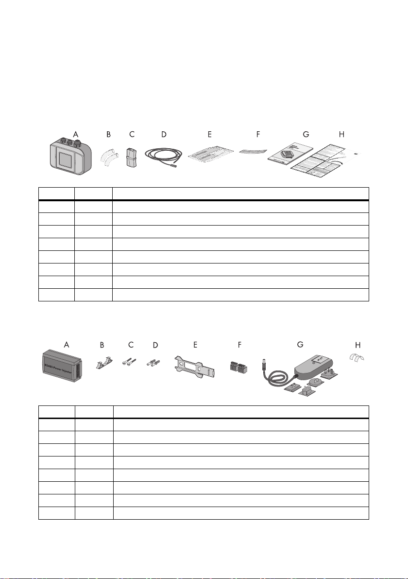
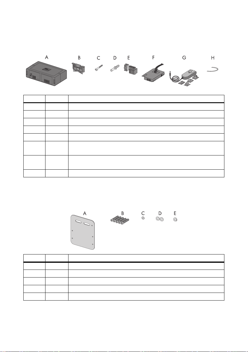
4.1 Packing List
Check the delivery for completeness and signs of damage. Please contact your dealer if the delivery
is not complete or you find any damage.
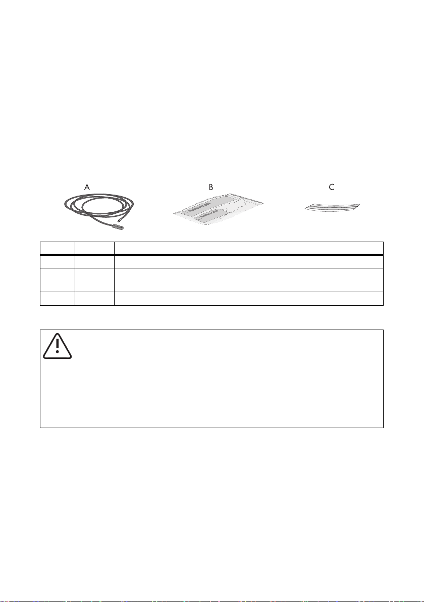
Position Quantity Designation
A 1 Sunny SensorBox with integrated solar radiation sensor
B2 Insulating tubes
C1 Terminal
D 1 PT100 module temperature sensor with 2.5 meter connection cable
E 1 Thermally conductive adhesive (protective gloves, hardener and binder)
F2Adhesive strips
G 1 Installation guide
H 1 RS485 cabling plan poster
RS485 Power Injector
Only with Sunny SensorBox order option: SUNNYSENSOR-1xxx
Position Quantity Designation
A 1 RS485 Power Injector
B1 Shield clamp
C2 Screws
D2 Wall anchors
E1 Wall mounting bracket
F 2 4-pole plugs
G 1 Plug-in power supply with plug adapter
H2 Conductive adhesive films
12 Sensorbox-IEN100914 Installation Guide
Page 13
SMA Solar Technology AG Unpacking
SMA Power Injector with Bluetooth
Only with Sunny SensorBox order option: SUNNYSENSOR-2xxx, SUNNYSENSOR-3xxx
Position Quantity Designation
A 1 SMA Power Injector with Bluetooth
B 1 Bracket for wall or top hat rail*
C1 Screw
D1 Wall anchor
E 1 Plug (1 x 2 poles, 1 x 4 poles)
F 1 Power module for supplying power (scope of delivery listed in power module
installation guide) - only with order option SUNNYSENSOR-3xxx
G 1 Plug-in power supply with plug adapter - only with order option
SUNNYSENSOR-2xxx
H1 Grounding cable
*
Can be found on the back of the SMA Power Injector with Bluetooth on delivery.
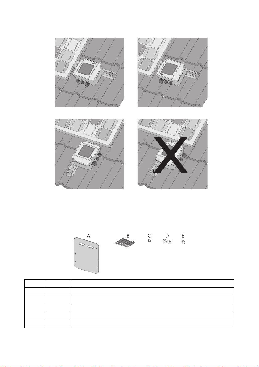
Module Frame Mounting Plate
Only with Sunny SensorBox order option: SUNNYSENSOR-x1xx
Position Quantity Designation
A 1 Mounting plate
B 5 M4 hexagonal screws
C1 M4 contact washer
D2 Washers
*
E1Locking washer
*
Pre-mounted on delivery.
Installation Guide Sensorbox-IEN100914 13
*
*
*
Page 14
Unpacking SMA Solar Technology AG
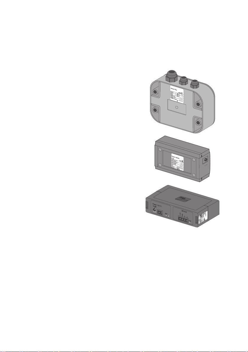
4.2 Identifying the Product
4.2.1 Type Label
Sunny SensorBox
You can identify the Sunny SensorBox by the type label.
The type label can be found on the bottom of the device.
RS485 Power Injector
You can identify the RS485 Power Injector by the type
label. The type label can be found on the bottom of the
device.
SMA Power Injector with Bluetooth
You can identify the SMA Power Injector with Bluetooth by
th e ty pe l abe l. T he t ype lab el c an b e fo und on t he r igh t si de
of the device.
4.2.2 Firmware Version
The firmware version of the Sunny SensorBox is displayed by the communication product (e.g., the
Sunny WebBox or Sunny Explorer) as follows:
• Via the "FwVer" display option for the RS485 Power Injector. To enable this option, select the
"Parameters" tab from the "Devices" navigation bar.
• Via the "Settings" device menu for the SMA Power Injector with Bluetooth. To enable this option,
select the "Type label > Central components" subgroup in the "Device components" parameter
group.
14 Sensorbox-IEN100914 Installation Guide
Page 15
SMA Solar Technology AG Device Overview
5 Device Overview
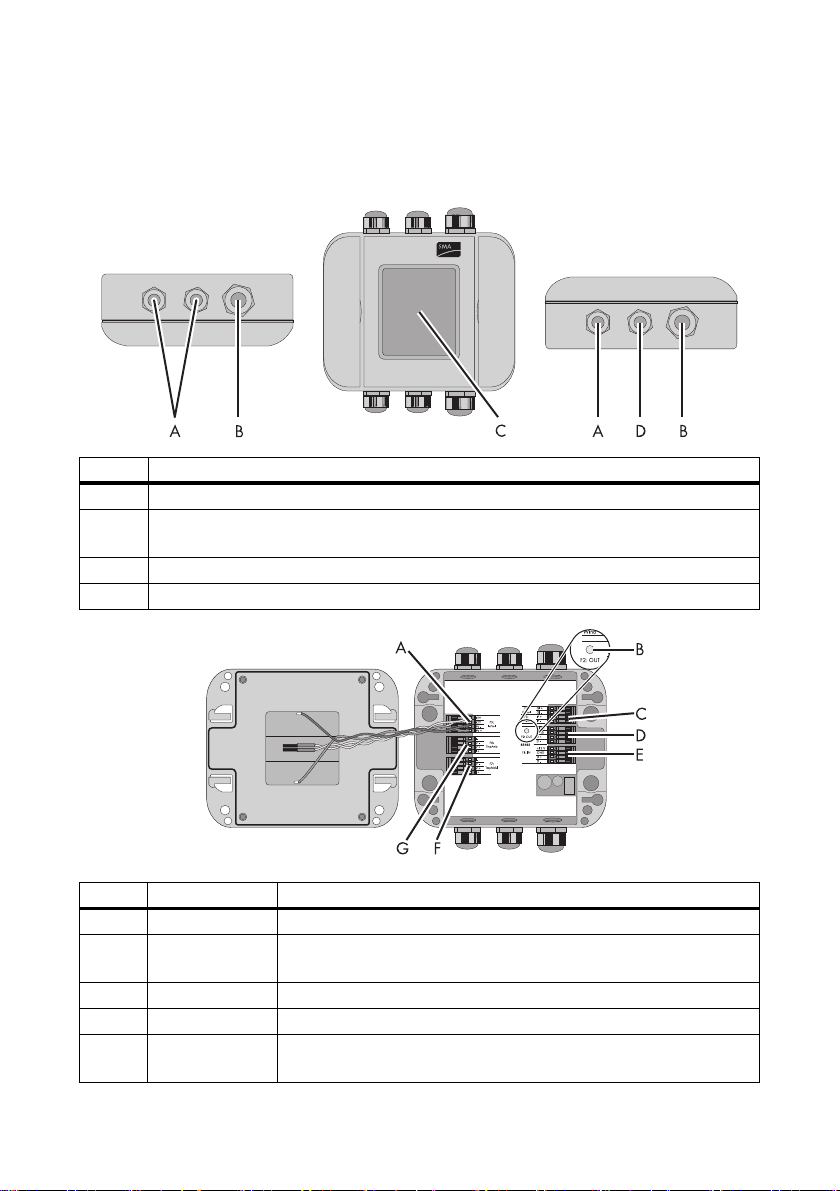
5.1 Device Overview of the Sunny SensorBox
Position Designation
A cable opening for the sensors
B cable opening for connecting the RS485 Power Injector or SMA Power Injector with
Bluetooth
C integrated solar radiation sensor
D cable opening for grounding the Sunny SensorBox
Position Designation Meaning
A "F5: IntSol" connection terminal for the integrated solar radiation sensor
BLED of the Sunny
SensorBox
C"F3: Wind" connection terminal for the anemometer
D"RS485 F2: OUT" connection terminal for additional RS485 bus nodes
E"RS485 F1: IN" connection terminal for the RS485 Power Injector or SMA Power
Installation Guide Sensorbox-IEN100914 15
LED for the status display of the Sunny SensorBox
Injector with Bluetooth
Page 16
Device Overview SMA Solar Technology AG
Position Designation Meaning
F"F7: TmpMdul" connection terminal for the module temperature sensor
G"F6: TmpAmb" connection terminal for the ambient temperature sensor
LED of the Sunny SensorBox
Status Meaning
Off • The Sunny SensorBox does not have power.
• during startup, the LED is switched off for 10 seconds
• during a reset, the LED is switched off for 60 seconds
Glows continuously Sunny SensorBox i s co nnected to th e po wer sup ply and ready
for operation
Flashes 2x very quickly Sunny SensorBox is connected to the power supply and
receiving data over the RS485 communication channel.
Flashes every second firmware malfunction (see section11”Troubleshooting”
(page68)).
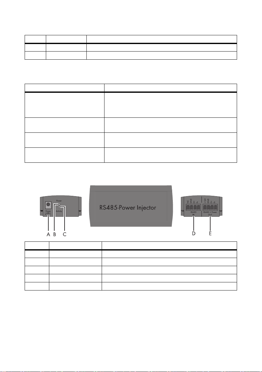
5.2 Device Overview of the RS485 Power Injector
Position Designation Meaning
A"Power" connection for the plug-in power supply
B"Power" LED LED for the Power Supply
C"Activity" LED LED for data traffic
D"RS485 IN" connection for the RS485 communication bus
E"RS485 + Power OUT" connection for the Sunny SensorBox
16 Sensorbox-IEN100914 Installation Guide
Page 17
SMA Solar Technology AG Device Overview
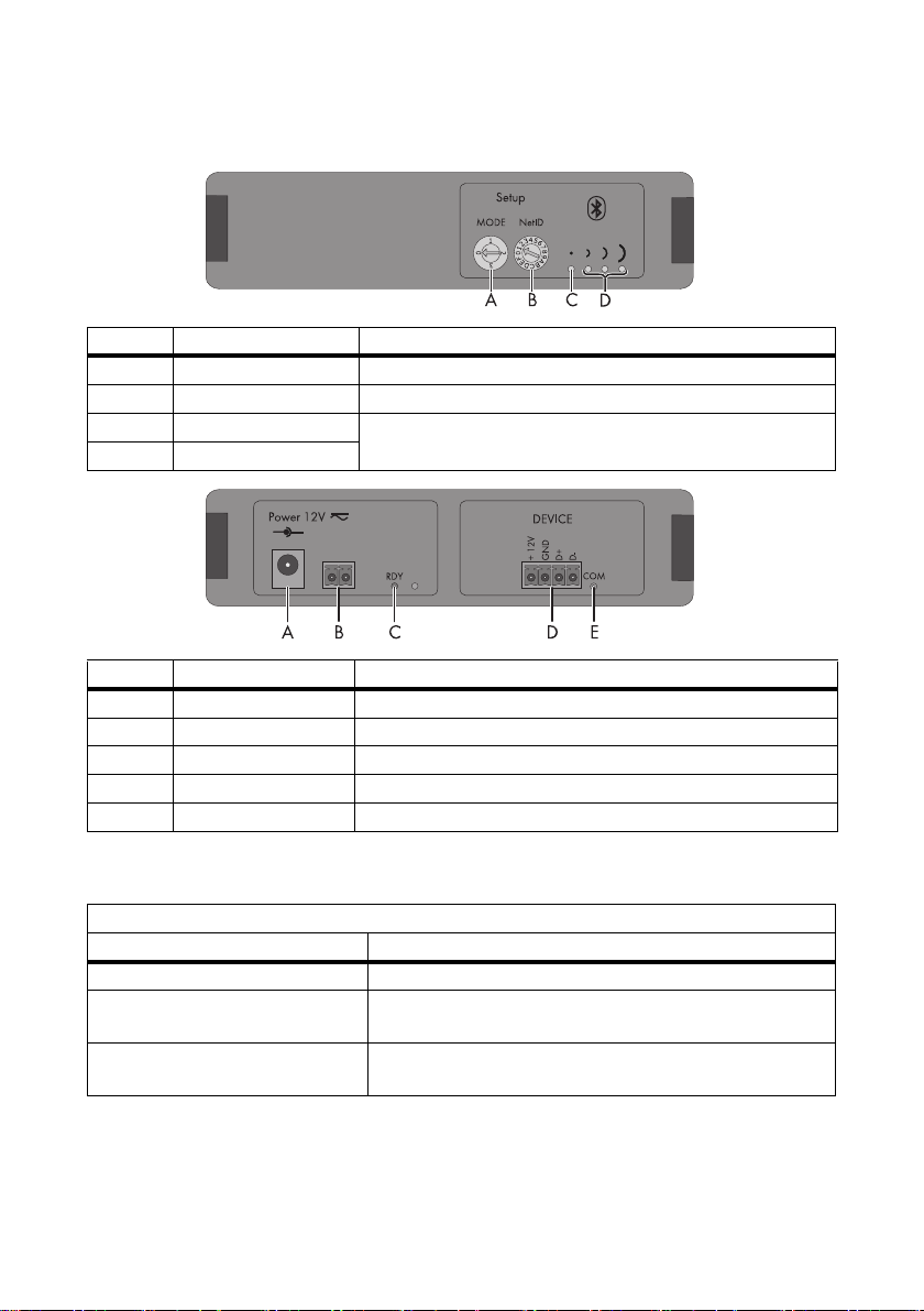
5.3 Device Overview of the SMA Power Injector with Bluetooth
Position Designation Meaning
A "MODE" rotary switch for the operating mode
B"NetID" rotary switch for the NetID
C Bluetooth LED (blue) LEDs for connection quality
D Bluetooth LEDs (yellow)
Position Designation Meaning
A"Power 12V ≂ " connection for the plug-in power supply, polarity is arbitrary
B 2-pole plug connection for the alternate power supply, polarity is arbitrary
C"RDY" LED (green) LED for the power supply
D"DEVICE" connection for the Sunny SensorBox
E"COM" LED (yellow) LED for data communication
5.3.1 LED for the Power Supply
RDY LED (green)
Status Meaning
Glows continuously supply voltage is ok, device is in operation
Flashes supply voltage is borderline, although the device is running,
stable operation is not guaranteed
Off supply voltage is either not available or too low, device is not
running
Installation Guide Sensorbox-IEN100914 17
Page 18
Device Overview SMA Solar Technology AG
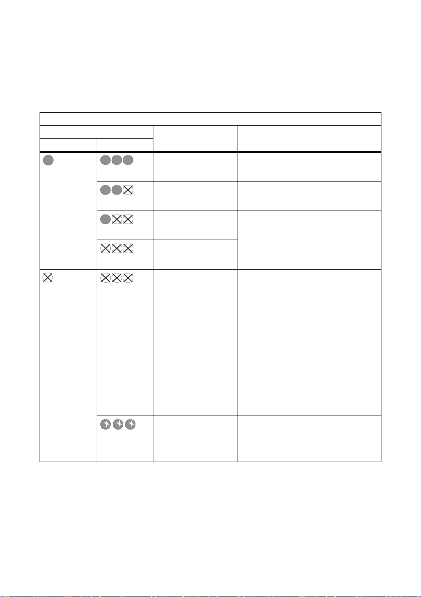
5.3.2 LEDs Indicating Connection Quality (Bluetooth LEDs)
The SMA Power Injector with Bluetooth must be added to an existing Bluetooth network before it can
display the connection quality. The Bluetooth network can only be set up using communication
products (e.g., Sunny WebBox with Bluetooth or Sunny Explorer).
Bluetooth LEDs
Status Connection quality Action
Blue LED Yellow LEDs
very good No action required.
Permanently on 3 LEDs on
good No action required.
2 LEDs on
unreliable Change the positioning or install an SMA
1 LED on
critical
no LEDs on
none The SMA Power Injector with Bluetooth is
Off no LEDs on
(special function) The rotary switch for the "NetID" is set to
3 LEDs flashing
Bluetooth Repeater.
not connected to the Bluetooth network:
• There is no device with the same
NetID within the radio range.
– Check the NetID.
– Change the positioning or
install an SMA Bluetooth
Repeater (see page 31).
•The Bluetooth network has not
been established. Only
communication products can
initiate network establishment.
position "1" or "0" (see section
6.4.3”Determining the Mounting/
Installation Location” (page31)).
18 Sensorbox-IEN100914 Installation Guide
Page 19
SMA Solar Technology AG Device Overview
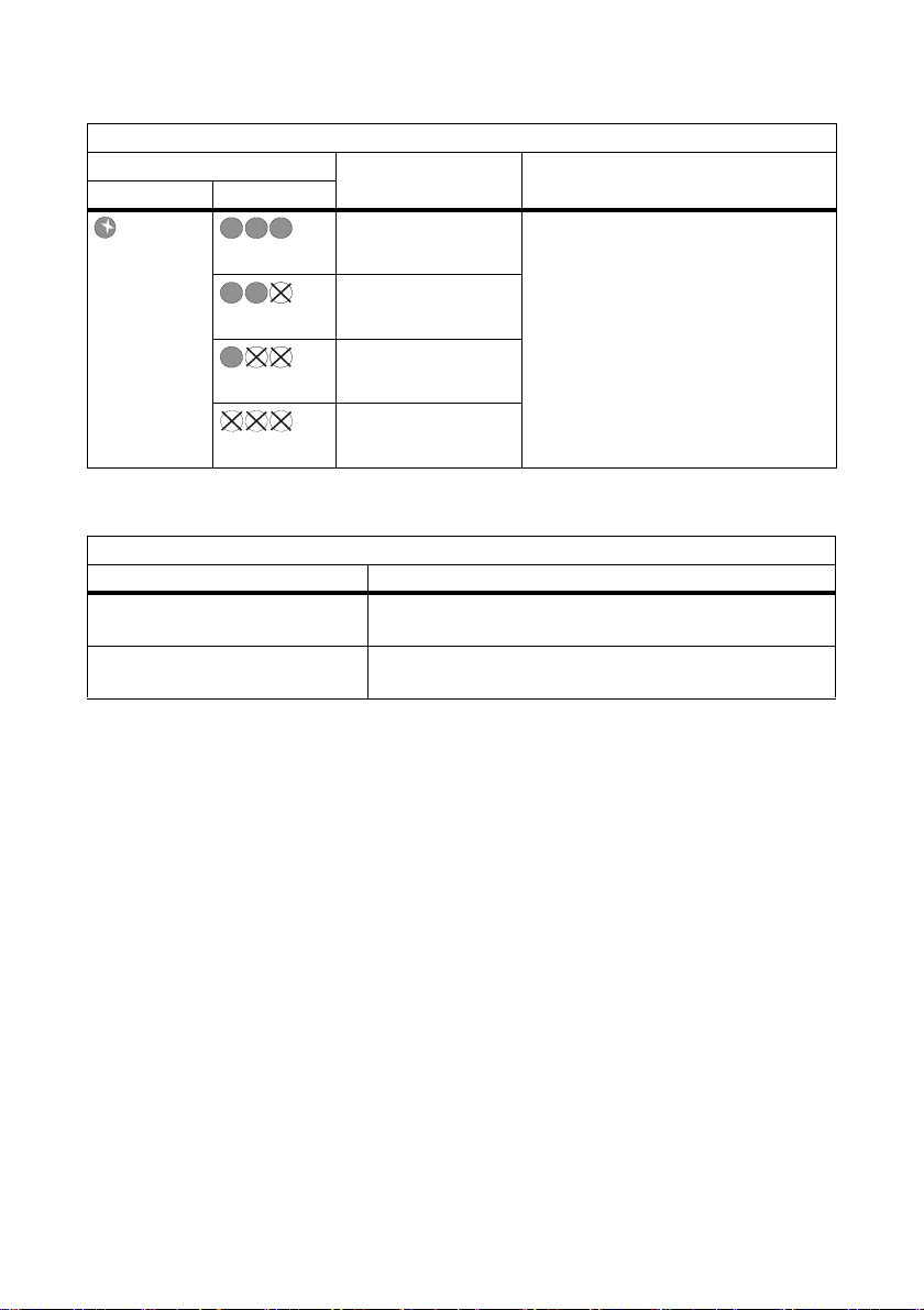
Bluetooth LEDs
Status Connection quality Action
Blue LED Yellow LEDs
very good Installation mode
Flashes 3 LEDs on
good
2 LEDs on
unreliable
1 LED on
critical
no LEDs on
The SMA Power Injector with Bluetooth is
in installation mode ("MODE 3"). The
sole purpose of this position is to
determine the location of installation (see
section 6.4.3”Determining the
Mounting/Installation Location”
(page31)). To exit the installation mode,
turn the "MODE" rotary switch to position
"0", "1" or "2".
5.3.3 LED for Data Communication
COM LED (yellow)
State Meaning
Flashes communication between the Sunny SensorBox and the SMA
Power Injector with Bluetooth.
Off no communication between the Sunny SensorBox and the
SMA Power Injector with Bluetooth
Installation Guide Sensorbox-IEN100914 19
Page 20

Mounting the Device SMA Solar Technology AG
6 Mounting the Device
6.1 Sunny SensorBox
6.1.1 Requirements for the Mounting Location
Mount the Sunny SensorBox either on the mounting rails of the PV mounting system or on rafters.
Observe the following information concerning the mounting location of the Sunny SensorBox:
• The Sunny SensorBox is suitable for outdoor installation.
• The ambient temperature must lie between –25 °C and +70 °C.
• If you decide to use the integrated solar radiation sensor, make sure the Sunny SensorBox is
mounted at the same tilt angle and orientation as the PV module so that the s ensor readings you
obtain can be directly compared to the yield of the PV system.
• Which mounting location to choose depends on which sensors are used. Observe the cable
lengths specified in the sensor manual.
• The maximum cable length from the final Sunny SensorBox to the RS485 Power Injector is
150 m.
• T he m axi mum cabl e le ngt h fr om th e Su nny Sen sor Box t o th e SMA Power Injector with Bluetooth
is 150 m.
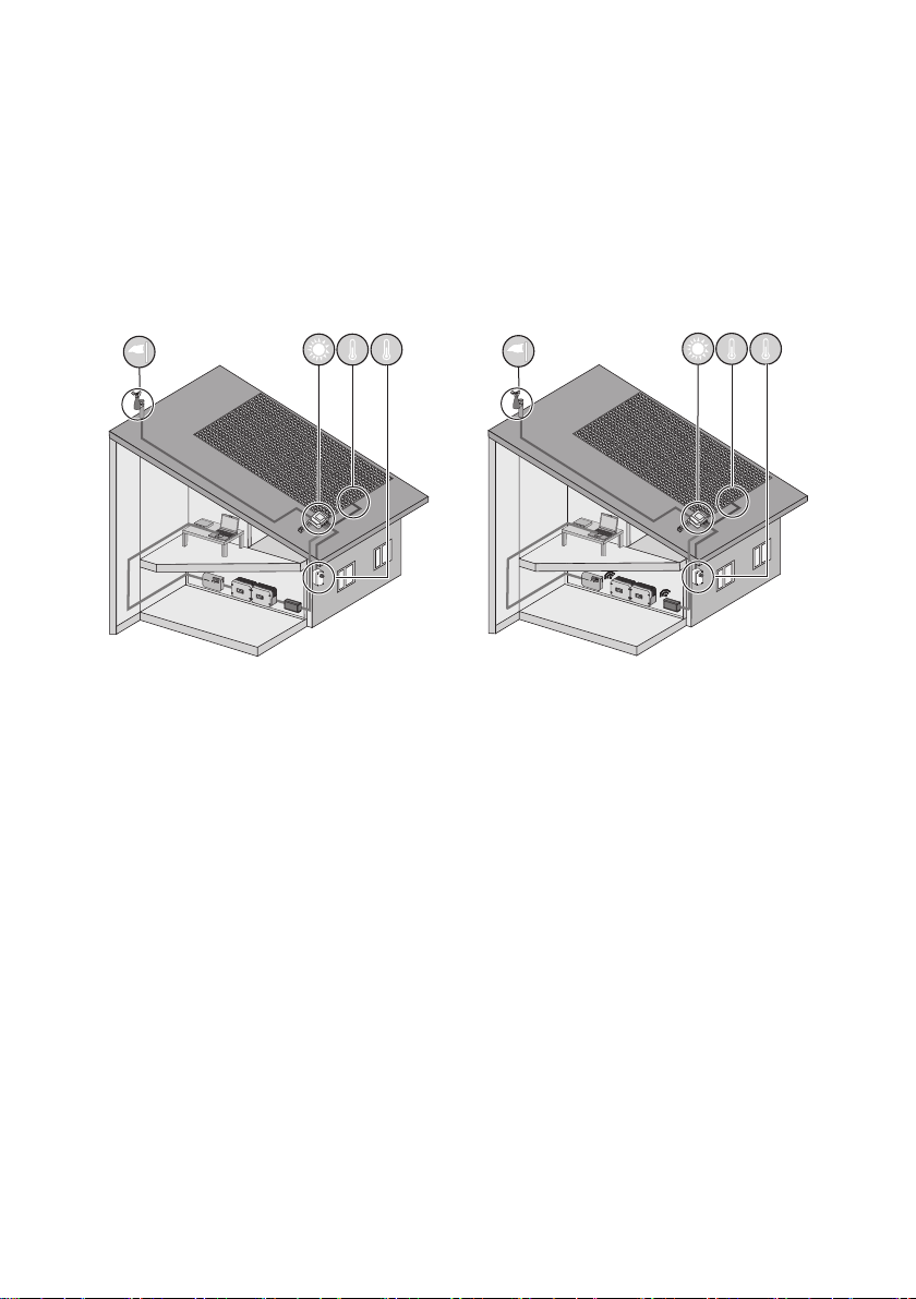
• As depicted below, the Sunny SensorBox may be mounted in three different alignments to keep
water from entering and damaging the device. The Sunny SensorBox may not be mounted
vertically with the SMA logo on the top, as this would allow water to penetrate into the device
through the ventilation membrane.
20 Sensorbox-IEN100914 Installation Guide
Page 21
SMA Solar Technology AG Mounting the Device
6.1.2 Mounting the Sunny SensorBox on a Mounting Rail
Included Mounting Accessories
Only with Sunny SensorBox order option: SUNNYSENSOR-x1xx
Position Quantity Designation
A 1 Mounting plate
B 5 M4 hexagonal screws
C1 M4 contact washer
D2 Washers
*
E1 Locking washer
*
Pre-mounted on delivery.
Installation Guide Sensorbox-IEN100914 21
*
*
*
Page 22
Mounting the Device SMA Solar Technology AG
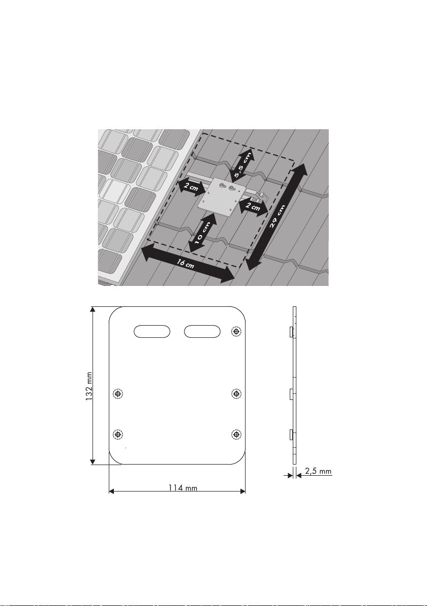
Mounting the Sunny SensorBox on a Mounting Rail
You can mount the device on a module frame provided the mounting rail protrudes from beneath the
sides of the modules by approximately 16 cm.
1. The mounting location should be determined based on the amount of space available and the
prescribed orientation of the Sunny SensorBox (see page 20).
22 Sensorbox-IEN100914 Installation Guide
Page 23
SMA Solar Technology AG Mounting the Device
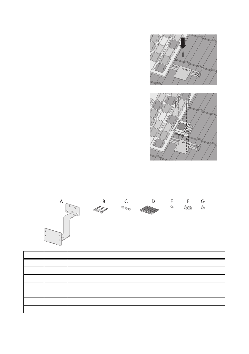
2. Attach the mounting plate onto the module rail with
the screws and slot nuts provided by the
manufacturer of the PV mounting system.
Usually any screw up to M10 in size fits into the slot
nuts.
3. Op en the si de f laps of t he S unn y Sensor Box usi ng the
notches as a guide.
4. Fasten the Sunny SensorBox onto the mounting plate
with four hexagonal screws. Make sure the Sunny
SensorBox is oriented correctly (see page 20).
☑ The Sunny SensorBox is now attached to the
mounting rail.
6.1.3 Mounting the Sunny SensorBox on Rafters
Optional Mounting Accessories
SMA order number: Roofan-Ssensor
Position Quantity Designation
A 1 Roof bracket
B 3 Hexagonal wood screws
C 3 Washers for hexagonal wood screws
D 5 M4 hexagonal screws
E1 M4 contact washer
F2 Washers
*
G1 Locking washer
*
Pre-mounted on delivery.
Installation Guide Sensorbox-IEN100914 23
*
*
*
Page 24
Mounting the Device SMA Solar Technology AG
Mounting the Sunny SensorBox on Rafters
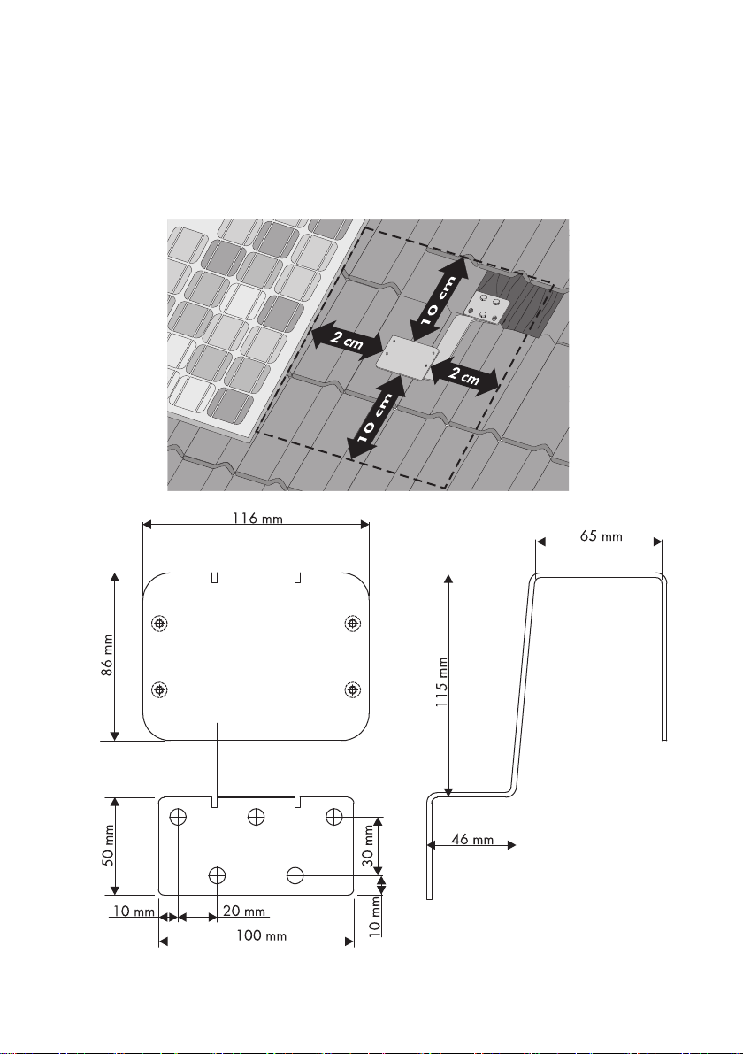
To mou nt t he d evi ce on a ra fte r, y ou fi rst nee d th e op tio nal r oof bracket (see section 14”Accessories”
(page78)).
1. The mounting location should be determined based on the amount of space available and the
prescribed orientation of the Sunny SensorBox (see page 20).
24 Sensorbox-IEN100914 Installation Guide
Page 25
SMA Solar Technology AG Mounting the Device
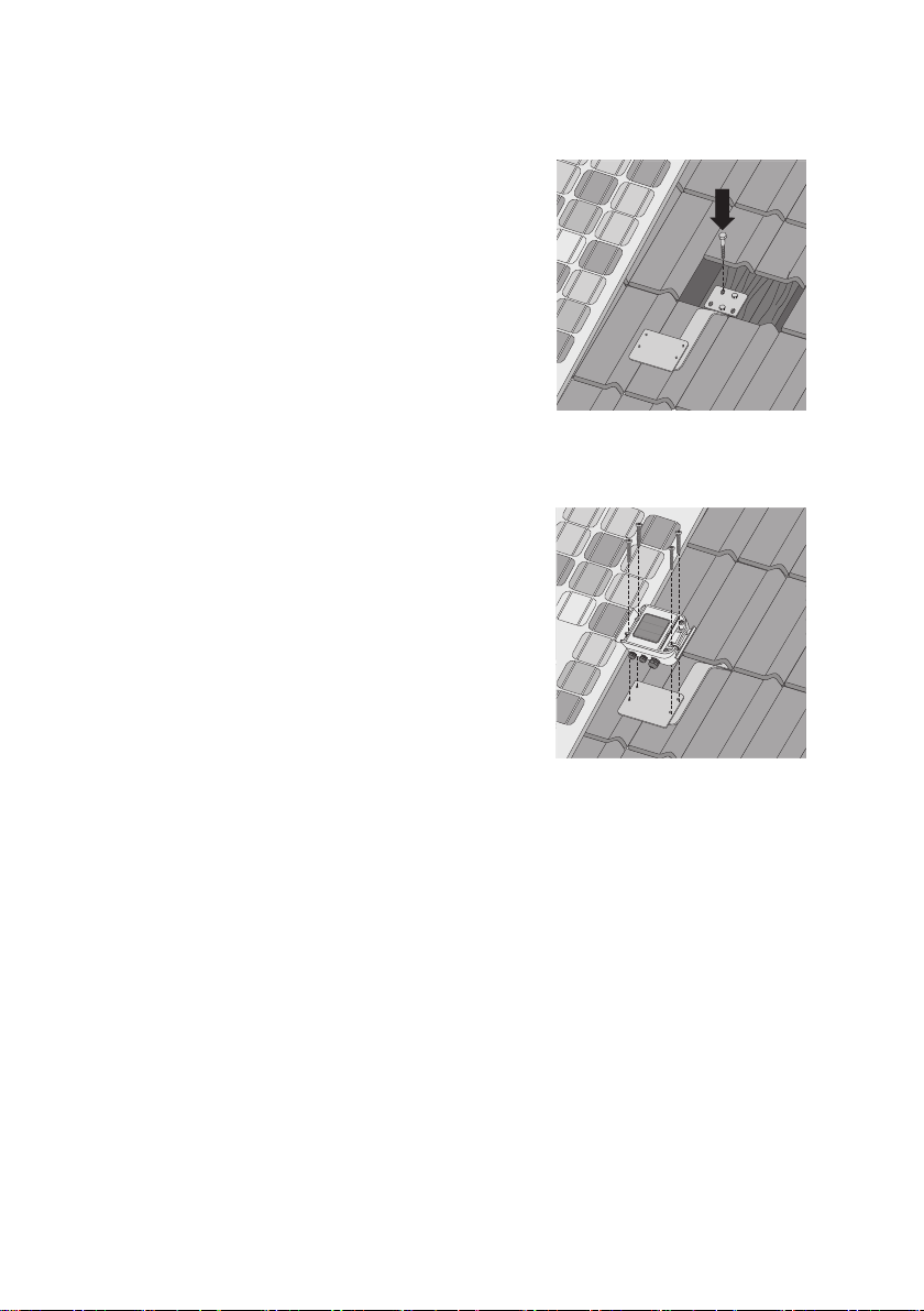
2. Uncover the rafters by removing the roof tiles in the mounting area.
3. Attach the roof bracket to the rafter using the three
wood screws and corresponding washers.
4. Incorporate the roof bracket into the existing lightning
protection system.
A means for attaching the lightning protection unit can be found on the lower slope of the roof
bracket (see page 54).
5. Using the notches as a guide, open the side flaps of
the Sunny SensorBox.
6. Fasten the Sunny SensorBox onto the mounting
bracket with four hexagonal screws. Make sure the
Sunny SensorBox is oriented correctly (see page 20).
7. Grind down the roof tiles if necessary.
8. Put the roof tiles back on the roof.
☑ The Sunny SensorBox is now mounted on the rafter.
Installation Guide Sensorbox-IEN100914 25
Page 26
Mounting the Device SMA Solar Technology AG
6.2 Mounting the Temperature Sensor on the PV Module
Requirements for the Mounting Location
Observe the following requirements regarding the mounting location of the module temperature
sensor:
• Select a PV module that remains unshaded throughout the day.
• Do not attempt to extend or shorten the pre-assembled 2.5 m cable.
• The module temperature sensor is affixed to the back of the PV module.
Included Mounting Accessories
Position Quantity Designation
A 1 PT100 module temperature sensor with 2.5 meter connection cable
B1 Thermally conductive adhesive (protective gloves, hardener and binder) with
instructions and packaging
C2 Adhesive strips
Mounting the Temperature Sensor on the PV Module
CAUTION!
Risk of chemical burns from contact with the thermally conductive adhesive.
• Avoid any contact with the skin, mucous membranes and eyes.
• Wear appropriate protective clothing, gloves and goggles when working on the
sensor.
• Follow the safety precautions and instructions from the manufacturer of the thermally
conductive adhesive.
1. The mounting location should be determined based on the cable length of the sensor and the
applicable site requirements.
26 Sensorbox-IEN100914 Installation Guide
Page 27
SMA Solar Technology AG Mounting the Device
2. Prepare the thermally conductive adhesive included in the delivery according to the
manufacturer's instructions. Observe the processing and hardening times specified by the
manufacturer.
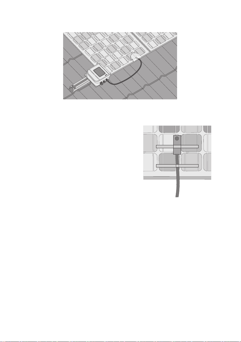
3. Affix the module temperature sensor to the bottom of
a PV module using the thermally conductive
adhesive.
4. Using strips of adhesive tape, affix the module
te mperatu re s ensor an d th e cable to t he botto m of the
PV module.
5. Once the thermally conductive adhesive is hardened, remove the adhesive tape strips.
☑ The module temperature sensor is now mounted.
Installation Guide Sensorbox-IEN100914 27
Page 28

Mounting the Device SMA Solar Technology AG
6.3 RS485 Power Injector
6.3.1 Requirements for the Mounting Location
Observe the following requirements regarding the mounting location of the RS485 Power Injector:
• The RS485 Power Injector is intended for indoor installation only.
• The mounting location must be in the vicinity of a 100 V … 240 V socket (power supply cable
length approx. 180 cm).
• Protect the RS485 Power Injector from dust, moisture and corrosive substances.
• The ambient temperature must remain between –20 °C and +65 °C.
• The maximum cable length from the final Sunny SensorBox to the RS485 Power Injector is
150 m.
• The maximum cable length of the entire RS485 communication bus is 1,200 m.
6.3.2 Mounting the RS485 Power Injector on a Wall
Included Mounting Accessories
Only with Sunny SensorBox order option: SUNNYSENSOR-1xxxx
Position Quantity Designation
A 1 Wall mounting bracket
B2 Screws
C2 Wall anchors
28 Sensorbox-IEN100914 Installation Guide
Page 29
SMA Solar Technology AG Mounting the Device
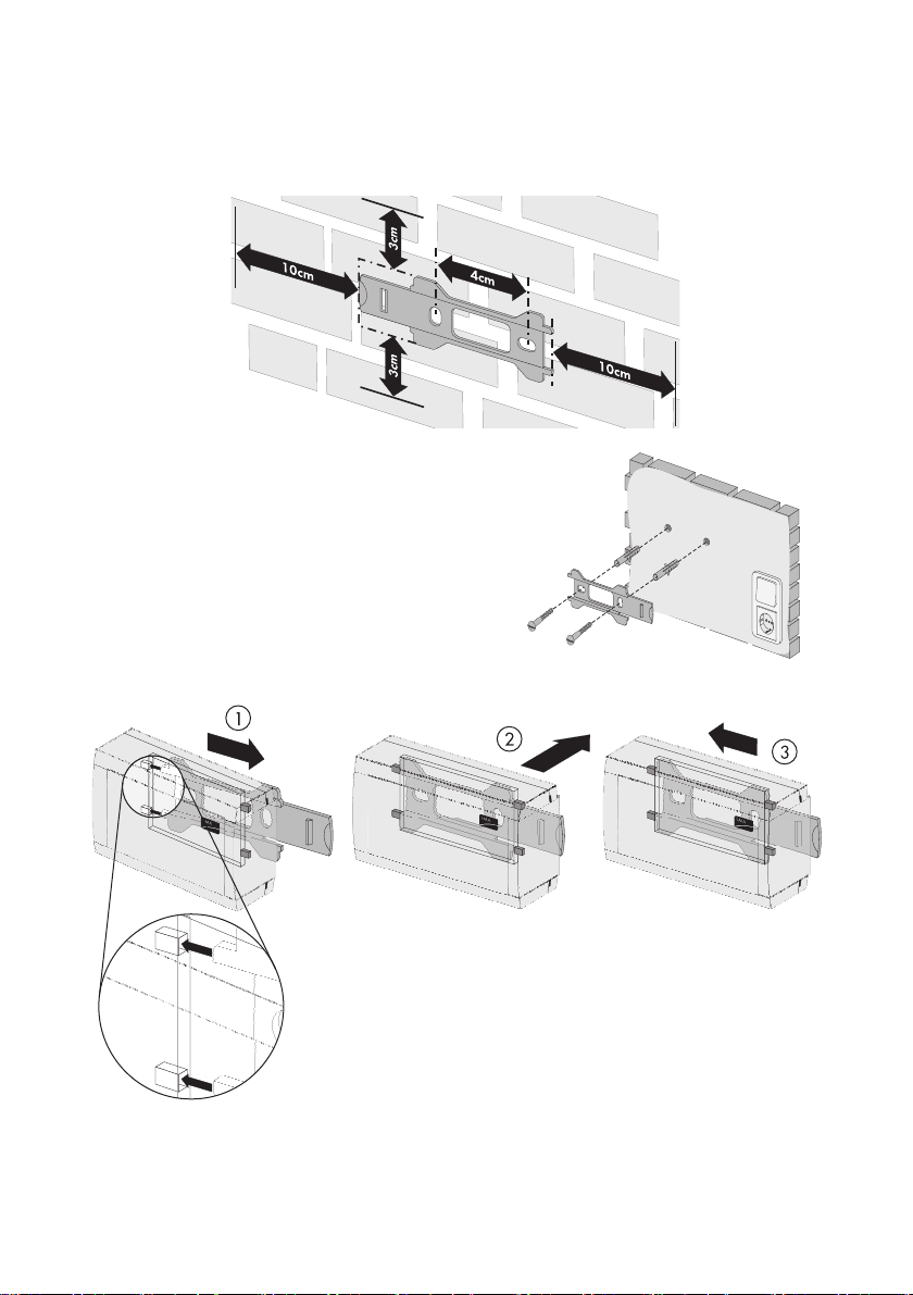
Mounting the RS485 Power Injector
1. Determine the mounting location based on the amount of available space.
2. Mark the position of the drill holes using the wall
mounting bracket as a guide.
3. Drill holes with a diameter of 6 mm at the marked
points and insert the wall anchors.
4. Attach the wall mounting bracket to the wall with two
screws.
5. Slide the RS485 Power Injector onto the wall
mounting bracket as shown in steps ① - ③ .
☑ The RS485 Power Injector is now mounted on the wall.
Installation Guide Sensorbox-IEN100914 29
Page 30

Mounting the Device SMA Solar Technology AG
6.4 SMA Power Injector with Bluetooth
6.4.1 Requirements for the Mounting Location
Observe the following requirements regarding the mounting location of the SMA Power Injector with
Bluetooth:
• The SMA Power Injector with Bluetooth is intended for indoor installation only.
• The mounting location must be in the vicinity of a 100 V … 240 V socket (plug-in power supply
cable length approx. 180 cm).
• Protect the SMA Power Injector with Bluetooth from dust, moisture and corrosive substances.
• The ambient temperature must remain between –20 °C and +65 °C.
• T he m axi mum cabl e le ngt h fr om th e Su nny Sen sor Box t o th e SMA Power Injector with Bluetooth
is 150 m.
• The maximum cable length for the alternate power supply device is 10 m.
• The wireless link at the mounting location should have a connection quality rating of "good" or
higher (see section 6.4.3”Determining the Mounting/Installation Location” (page31).
• Certain ambient conditions can reduce the connection quality and data transmission speed
between Bluetooth devices.
– Mount or install the Bluetooth device at a distance of at least 1 m from the following devices:
–WLAN devices
– Microwave ovens
– Other devices that use the 2.4 GHz frequency band
6.4.2 Information on SMA Bluetooth
The SMA Bluetooth devices of your PV system can communicate and network with an SMA Bluetooth
communication product via Bluetooth wireless technology. To ensure the devices communicate with
each other and are interlinked, they have to be set to the same NetID. The NetID is the unique
identification number of your PV system. It can therefore be used to distinguish your PV system from
other SMA Bluetooth PV systems.
Determining the NetID for your PV System
If your Bluetooth PV system does not have a NetID yet, you first need to determine a free
NetID with the Sunny Explorer or Sunny Beam with Bluetooth software applications and
then set the devices of your PV system accordingly.
30 Sensorbox-IEN100914 Installation Guide
Page 31
SMA Solar Technology AG Mounting the Device
Extending the Bluetooth Network with the SMA Bluetooth Repeater
The SMA Bluetooth Repeater can help you extend the wireless range of your Bluetooth network.
When an SMA Bluetooth Repeater is set up at the coverage boundary of a Bluetooth network, it is
capable of routing the data traffic in that network into its own wireless range. This technology allows
you to set up Bluetooth networks that cover a much larger area than would be possible with just the
Sunny SensorBox or SMA Power Injector with Bluetooth.
Further information about SMA Bluetooth Wireless Technology can be found in the download section
at www.SMA.de/en.
6.4.3 Determining the Mounting/Installation Location
Before mounting the SMA Power Injector with Bluetooth, you should first test the wireless connection
between the device and your PV system at the specified mounting/installation location. The Sunny
SensorBox does not have to be connected to the SMA Power Injector with Bluetooth in order to
perform this test.
To do so, proceed as follows:
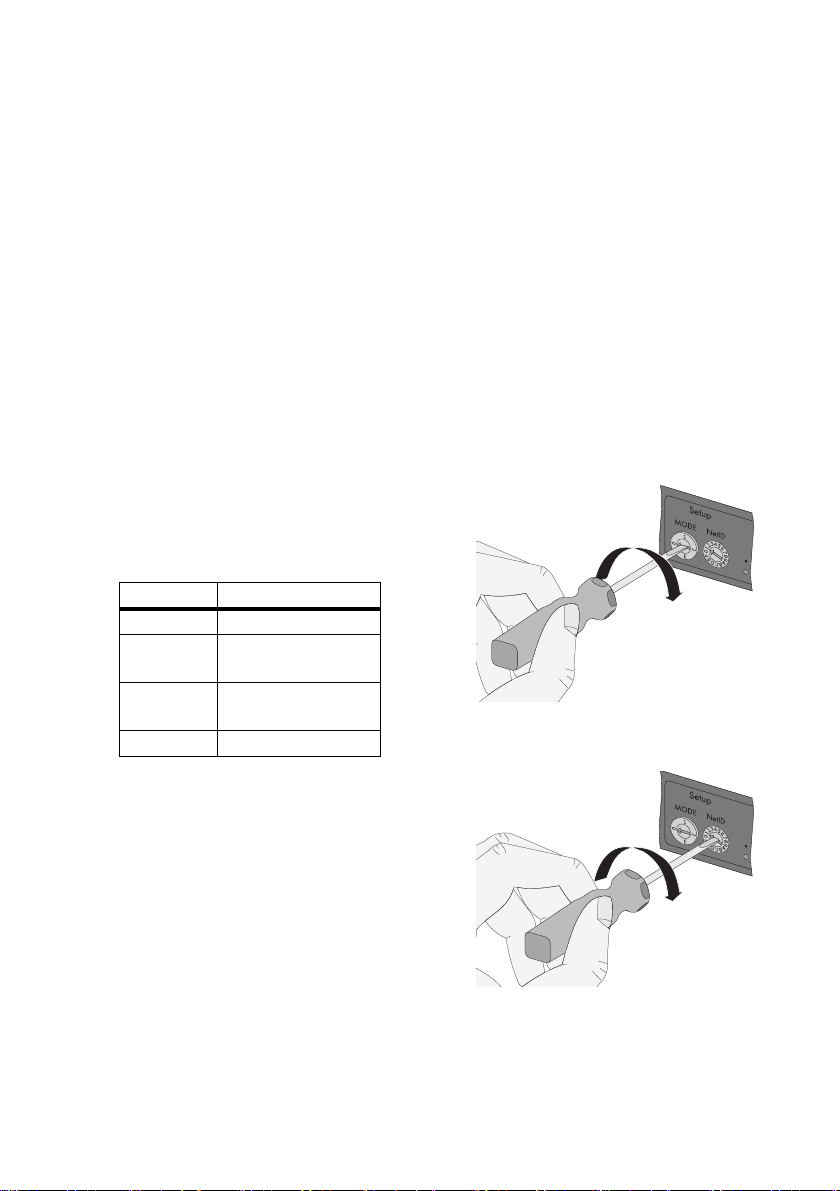
1. Turn the "MODE" rotary switch of the
SMA Power Injector with Bluetooth to position "3".
The sole purpose of this position is to determine the
location of installation.
"MODE" ID Meaning
0 normal operation
1 for servicing purposes
only
2 for servicing purposes
only
3 installation mode
2. Turn the "NetID" rotary switch of the SMA Power
Injector with Bluetooth to the NetID of your PV
system. If your PV system does not have a NetID
yet, see section 6.4.2”Information on SMA
Bluetooth” (page30).
Installation Guide Sensorbox-IEN100914 31
Page 32

Mounting the Device SMA Solar Technology AG
Layout of the switch positions
NetID Function
0 Bluetooth is switched off.
The three yellow Bluetooth LEDs flash.
1
(Status upon delivery)
Bluetooth is switched on.
The SMA Power Injector with Bluetooth can accept no more than two
connections from a communication product such as a Bluetooth-
enabled computer running Sunny Explorer or Sunny WebBox with
Bluetooth. A connection to the Sunny Beam with Bluetooth is not
possible.
The three yellow Bluetooth LEDs flash.
2 - F Bluetooth is switched on.
The SMA Power Injector with Bluetooth can network with all SMA
Bluetooth products that share the same NetID. A connection to the
Sunny Beam with Bluetooth is not possible.
3. Connecting the SMA Power Injector with Bluetooth to the power supply (see section
7.6.4”Connecting the SMA Power Injector with Bluetooth to the Power Supply” (page58)).
☑ The SMA Power Injector with Bluetooth shows the connection quality to the next available
SMA Bluetooth device. You can change the connection quality by moving the Bluetooth
devices further apart or shifting their orientation. The connection quality must be rated as
"good" or higher for the selected mounting/installation location (at least two yellow
Bluetooth LEDs glow).
– You must improve any connection that proves to be unreliable or too slow (see section
5.3.2”LEDs Indicating Connection Quality (Bluetooth LEDs)” (page18)).
4. Disconnect the power and turn the rotary switch to "MODE 0".
☑ The mounting/installation location for the SMA Power Injector with Bluetooth has now been
determined.
Once you have determined the best mounting location, you can mount the SMA Power Injector with
Bluetooth on a wall or top hat rail.
32 Sensorbox-IEN100914 Installation Guide
Page 33

SMA Solar Technology AG Mounting the Device
6.4.4 Mounting the SMA Power Injector with Bluetooth on a Wall
Included Mounting Accessories
Position Quantity Designation
A 1 Bracket*
B1 Screw
C1 Wall anchor
*
Can be found on the back of the SMA Power Injector with Bluetooth on delivery.
1. Remove the bracket from the back of the SMA
Power Injector with Bluetooth as depicted here.
2. The mounting location should be determined
based on the space available and the quality of the wireless connection to the Bluetooth
network
3. Label the drill hole.
4. Drill a 6 mm diameter hole at the designated point and then insert a wall anchor.
5. Fasten the bracket to the wall with a screw.
Installation Guide Sensorbox-IEN100914 33
Page 34

Mounting the Device SMA Solar Technology AG
6. Slide the SMA Power Injector with Bluetooth into the bracket as illustrated here.
☑ The SMA Power Injector with Bluetooth is now mounted.
Information on how to detach the SMA Power Injector with Bluetooth from the wall can be found in
section 10.3”Dismantling the SMA Power Injector with Bluetooth” (page66).
6.4.5 Mounting the SMA Power Injector with Bluetooth on a Top Hat Rail
Included Mounting Accessories
Position Quantity Designation
A1 Bracket
*
Can be found on the back of the SMA Power Injector with Bluetooth on delivery.
*
1. Remove the bracket from the back of the SMA
Power Injector with Bluetooth as depicted here.
34 Sensorbox-IEN100914 Installation Guide
Page 35

SMA Solar Technology AG Mounting the Device
2. Hook the ridge at the top of the SMA Power
Injector with Bluetooth into the top edge of the top
hat rail.
3. Press the SMA Power Injector with Bluetooth do wn
on the top hat rail and hold.
4. Press the middle of the bracket down into the guide rail until it snaps into place.
☑The SMA Bluetooth Repeater is now mounted.
Information on how to detach the SMA Power Injector with Bluetooth from the top-hat rail can be
found in section 10.3”Dismantling the SMA Power Injector with Bluetooth” (page66).
Installation Guide Sensorbox-IEN100914 35
Page 36

Startup SMA Solar Technology AG
7 Startup
7.1 Information on Starting up the Device
This section shows you how to connect external sensors and start up the Sunny SensorBox with the
RS485 Power Injector or the SMA Power Injector with Bluetooth.
For initial startup, the following steps must be taken:
• Connect the module temperature sensor (see page 36).
• If necessary, connect the anemometer (see page 38).
• If necessary, connect the ambient temperature sensor (see page 39).
• Connect the Sunny SensorBox to the RS485 communication bus via the RS485 Power Injector
and turn it on (see page40) or connect the Sunny SensorBox to the SMA Power Injector with
Bluetooth and turn it on (see page 53).
NOTICE!
Damage to the Sunny SensorBox from water seeping in.
• When inserting or removing the cable
through the cable gland, make sure the
gasket is properly seated in the cable
gland.
7.2 Connecting the Module Temperature Sensor
Cable length when connecting in a 2-conductor technology
The connection is made via a 2.5 m cable. The cable may not be extended or cut. The
measurement accuracy depends on the cable length.
1. Open the Sunny SensorBox (see page 61).
2. Unscrew the cable gland's lock nut on the bottom left
of the Sunny SensorBox and remove the filler plugs.
3. Thread the sensor cable through the lock nut and the
cable gland at the bottom left and into the enclosure
of the Sunny SensorBox and then tighten the cable
gland.
36 Sensorbox-IEN100914 Installation Guide
Page 37

SMA Solar Technology AG Startup
4. Connect the sensor on the "F7: TmpMdul" terminal of
the Sunny SensorBox. The polarity of the cables is
arbitrary.
5. Make sure the gasket of the cable gland is properly seated.
6. Screw the lock nut onto the cable gland until finger tight to fix the cable (torque: 0.8 Nm).
7. Securely lay the cable using suitable fastening material.
☑ The module temperature sensor is connected.
You can now connect additional sensors or connect the Sunny SensorBox via the RS485 Power
Injector or the SMA Power Injector with Bluetooth and turn it on.
Installation Guide Sensorbox-IEN100914 37
Page 38

Startup SMA Solar Technology AG
7.3 Connecting the Anemometer
Specified cable length when connecting to the SensorBox
• Note the cable length specified in the sensor manual.
1. Open the Sunny SensorBox (see page 61).
2. Unscrew the cable gland's lock nut on the top left of the Sunny SensorBox and remove the filler
plugs.
3. Thread the sensor cable through the lock nut and
the cable gland at the top left and into the
enclosure of the Sunny SensorBox and then tighten
the cable gland.
4. Connect the sensor on the "F3: Wind" terminal of
the Sunny SensorBox. The polarity of the cables is
arbitrary.
5. Make sure the gasket of the cable gland is properly seated.
6. Screw the lock nut onto the cable gland until finger tight (torque: 0.8 Nm).
7. Lay the cable using suitable fastening material.
☑ The anemometer is connected.
You can now connect additional sensors or connect the Sunny SensorBox via the RS485 Power
Injector or the SMA Power Injector with Bluetooth and turn it on.
38 Sensorbox-IEN100914 Installation Guide
Page 39

SMA Solar Technology AG Startup
7.4 Connecting the Ambient Temperature Sensor
Specified cable length when connecting to the SensorBox
• Note the cable length specified in the sensor manual.
1. Open the Sunny SensorBox (see page 61).
2. Unscrew the cable gland's lock nut on the bottom
ce nter of t he S unn y Sensor Box and re mov e the fil ler
plugs.
3. Thread the sensor cable through the lock nut and
the cable gland to the bottom center and then
tighten the cable gland.
4. Rem ove the termin ation resist or and the bri dge fro m
the "F6: TmpAmp" terminal of the Sunny SensorBox.
5. Connect the sensor to the "F6: TmpAmb" terminal of
the Sunny SensorBox.
6. Make sure the gasket of the cable gland is properly seated.
7. Screw the lock nut onto the cable gland until finger tight (torque: 0.8 Nm).
8. Lay the cable using suitable fastening material.
☑ The ambient temperature sensor is connected.
You can now connect additional sensors or connect the Sunny SensorBox via the
RS485 Power Injector or the SMA Power Injector with Bluetooth and turn it on.
Installation Guide Sensorbox-IEN100914 39
Page 40

Startup SMA Solar Technology AG
7.5 Startup via the RS485-Power Injector
7.5.1 Information on Starting up the Device
The RS485 Power Injector is used to integrate the Sunny SensorBox into the RS485 communication
bus. The RS485 Power Injector is designed to supply the Sunny SensorBox with power. It is
recommended that you place the Sunny SensorBox at the end of the RS485 communication bus. The
required termination has already been pre-wired.
Information on RS485 cabling
See the RS485 cabling plan poster for information on RS485 cabling.
To connect the Sunny SensorBox to the RS485 communication bus, proceed as follows:
① Connect the RS485 Power Injector to an RS485 bus node (see page 41).
② Connect the RS485 Power Injector to the Sunny SensorBox (see page 43).
③ Connect the RS485 Power Injector to the power supply (see page 52).
The following options are also available:
• Connect the Sunny SensorBox to another Sunny SensorBox (see page 46)
• Connect the Sunny SensorBox to another RS485 bus node (see page 50)
40 Sensorbox-IEN100914 Installation Guide
Page 41

SMA Solar Technology AG Startup
7.5.2 Connecting the RS485-Power Injector to an RS485 Bus Node
RS485 Bus Node
1. Connect the cables to the RS485 bus nodes as described in the RS485 bus node manual.
RS485 Power Injector
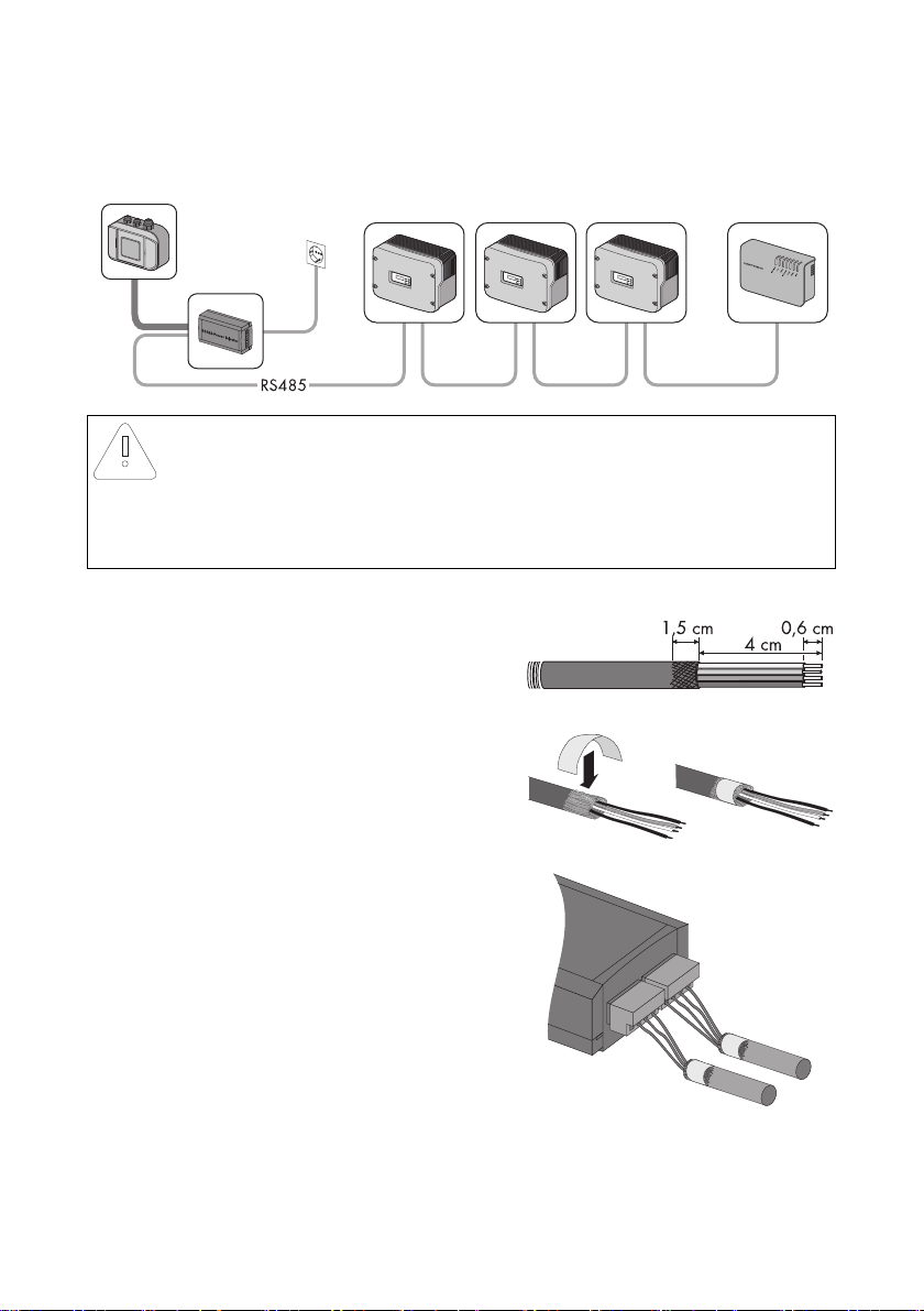
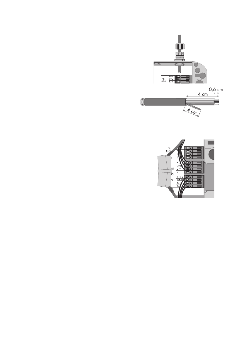
2. Remove about 4 cm of cable sleeve from the RS485
Power Injector end of the RS485 communication
cable.
3. Shorten the cable shield by 1.5 cm.
4. Pull back the cable shield and cover with conductive
adhesive film. This is where the shield clamp will be
attached later.
5. Shorten unused wires until flush with the cable sleeve.
6. Strip approx. 6 mm of insulation from the wires.
Connection layout and system wiring
See the RS485 cabling plan poster for the connection layout and system wiring.
Installation Guide Sensorbox-IEN100914 41
Page 42
Startup SMA Solar Technology AG
7. Connect the wires to the plug. Note the
configurations in your RS485 communication bus.
If necessary, write down the color of the wires.
2 | D+ ________________________
5 | GND ________________________
7 | D- ________________________
8. Insert the plug into the "RS485 IN" socket of the
RS485 Power Injector.
☑ The RS485 Power Injector is connected to the RS485 communication bus.
You can now connect the RS485 Power Injector to the Sunny SensorBox.
42 Sensorbox-IEN100914 Installation Guide
Page 43
SMA Solar Technology AG Startup
7.5.3 Connecting the RS485 Power Injector to the Sunny SensorBox
NOTICE!
Short circuit due to faulty wiring.
The RS485 Power Injector must be connected directly to the Sunny SensorBox. To avoid
the possibility of a short circuit, do not connect any other RS485 bus node between these
two devices.
RS485 Power Injector
1. Remove about 4 cm of cable sleeve from the
RS485 Power Injector end of the RS485
communication cable.
2. Shorten the cable shield by 1.5 cm.
3. Pull back the cable shield and cover with conductive
adhesive film. This is where the shield clamp will be
attached later.
4. Shorten unused wires until flush with the cable sleeve.
5. Strip approx. 6 mm of insulation from the wires.
6. Connect the wires with the plug.
Write down the color of the wires:
+12V ________________________
GND ________________________
D+ ________________________
D - ________________________
7. Insert the plug into the "RS485+Power OUT" socket
of the RS485 Power Injector.
☑ The RS485 Power Injector is connected.
Installation Guide Sensorbox-IEN100914 43
Page 44

Startup SMA Solar Technology AG
8. Attach the shield clamp.
9. Route the RS485 communication cable from the RS485 Power Injector to the Sunny SensorBox.
Sunny SensorBox
10. Open the Sunny SensorBox (see page 61).
11. Unscrew the cable gland's lock nut on the bottom
right of the Sunny SensorBox and remove the filler
plugs.
12. Thread the RS485 communication cable through
the lock nut and the cable gland and into the
enclosure of the Sunny SensorBox.
NOTICE!
Damage to the Sunny SensorBox caused by metal or cable scraps left inside the
device.
• When working on the cable, make sure that no metal scraps from the cable shield or
cable itself fall into the Sunny SensorBox while it is open.
13. Remove 4 cm of cable sleeve from the RS485
communication cable that is connected to the
Sunny SensorBox.
14. Strip approx. 6 mm of insulation from the wires.
15. Twist the cable shield into one string. The cable
shield is only needed if another Sunny SensorBox is connected.
16. Pull the insulating tube over the cable shield. Allow 4 cm of the cable shield to stick out of the
insulating tube.
44 Sensorbox-IEN100914 Installation Guide
Page 45
SMA Solar Technology AG Startup
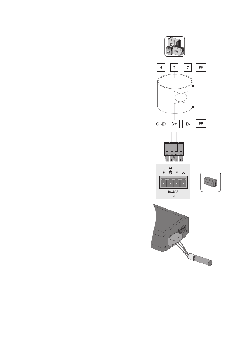
+12V
GND
D+
D-
RS485 + Power
OUT
D+
GND
+12V
D-
D+
GND
+12V
D-
PE
PE
+12 V
GND
D +
D -
F1: IN
RS485
D -
17. Insert the detached cable shield into the terminal.
18. Connect the wires to the "RS485 F1: IN" terminal of
the Sunny SensorBox. Observe the noted wire colors.
19. Make sure the gasket of the cable gland is properly seated.
20. Screw the lock nut onto the cable gland until finger tight to fix the cable (torque: 0.8 Nm).
Installation Guide Sensorbox-IEN100914 45
Page 46
Startup SMA Solar Technology AG
21. If necessary, connect another Sunny SensorBox or RS485 bus node (see pages 46 or 50).
22. Check the RS485 cabling plan poster to find out whether the terminating resistor has to be
plugged into the "RS485 F2: OUT" terminal.
23. Close the Sunny SensorBox (see page 61).
☑ The RS485 Power Injector is connected to the Sunny SensorBox.
7.5.4 Connecting the Sunny SensorBox to another Sunny
SensorBox
You can add an additional Sunny SensorBox to the Sunny SensorBox. If you do add another one,
note that you can use the RS485 Power Injector to supply power to up to five Sunny SensorBoxes in
total.
Connection to an Installed Sunny SensorBox
NOTICE!
Damage to the Sunny SensorBox caused by metal or cable scraps left inside the
device.
• When working on the cable, make sure that no metal scraps from the cable shield or
cable itself fall into the Sunny SensorBox while it is open. Remov e any metal or cable
scraps if present.
1. Open the Sunny SensorBox (see page 61).
2. Remove the termination resistor for "F2: OUT RS485"
on the installed Sunny SensorBox.
46 Sensorbox-IEN100914 Installation Guide
Page 47
SMA Solar Technology AG Startup
3. Unscrew the cable gland's lock nut at the top right
of the installed Sunny SensorBox and remove the
filler plugs.
4. Thread the RS485 communication cable through
the lock nut and the cable gland and into the
enclosure of the installed Sunny SensorBox.
5. Remove 4 cm of cable sleeve from the RS485
communication cable that is connected to the
installed Sunny SensorBox.
6. Strip approx. 6 mm of insulation from the wires.
7. Twist the cable shield into one string.
8. Pull the insulating tube over the cable shield. Allow
4 cm of the cable shield to stick out of the insulating tube.
9. Insert the detached cable shield into the terminal.
10. Connect the wires to the "F2: OUT RS485" terminals
of the installed Sunny SensorBox.
Write down the color of the wires:
+12V ________________________
GND ________________________
D+ ________________________
D- ________________________
11. Make sure the gasket of the cable gland is properly seated.
12. Screw the lock nut onto the cable gland until finger tight to fix the RS485 communication cable
(torque: 0.8 Nm).
13. Close the installed Sunny SensorBox (see page 61).
☑ The RS485 communication cable is now connected to the installed Sunny SensorBox.
Connection to the Sunny SensorBox you Want to Connect
14. Mount the Sunny SensorBox you want to connect as described in section 6”Mounting the
Device” (page20).
15. Open the Sunny SensorBox (see page 61).
16. Unscrew the cable gland's lock nut on bottom right of the Sunny SensorBox you want to connect
and remove the filler plugs.
Installation Guide Sensorbox-IEN100914 47
Page 48

Startup SMA Solar Technology AG
17. Thread the RS485 communication cable through
the lock nut and the cable gland and into the
enclosure of the Sunny SensorBox.
18. Remove 4 cm of cable sleeve from the RS485
communication cable that is connected to the
Sunny SensorBox.
19. Strip approx. 6 mm of insulation from the wires.
20. Twist the cable shield into one string. The cable
sh iel d is onl y ne ede d if ano the r Su nny Sens orB ox i s
connected.
21. Pull the insulating tube over the cable shield. Allow 4 cm of the cable shield to stick out of the
insulating tube.
22. Insert the detached cable shield into the terminal.
48 Sensorbox-IEN100914 Installation Guide
Page 49

SMA Solar Technology AG Startup
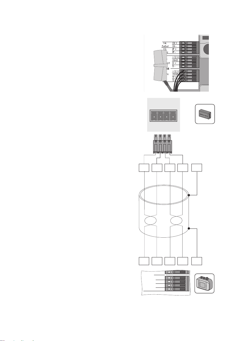
D+
GND
+12V
D-
D+
GND
+12V
D-
PE
PE
+12 V
F2: OUT
RS485
IP -
+12 V
GND
D +
D -
Wind
+12 V
F2: OUT
RS485
IP -
+12 V
GND
D +
D -
Wind
23. Connect the RS485 communication cable to the
"F1: IN RS485" terminals of the Sunny SensorBox.
Observe the noted wire colors.
24. Make sure the gasket of the cable gland is properly seated.
25. Screw the lock nut onto the cable gland until finger tight to fix the RS485 communication cable
(torque: 0.8 Nm).
26. If necessary, connect another Sunny SensorBox or RS485 bus node (see pages 46 or 50).
27. Make sure the termination resistor is plugged in (see section 9.2”Terminating the RS485 Bus
on the Sunny SensorBox” (page62)).
28. Close the Sunny SensorBox (see page 61).
☑ The additional Sunny SensorBox is now connected.
Installation Guide Sensorbox-IEN100914 49
Page 50

Startup SMA Solar Technology AG
7.5.5 Connecting the Sunny SensorBox to an Additional RS485 Bus
Node
1. Open the Sunny SensorBox (see page 61).
2. Remove the termination resistor at "F2: OUT RS485"
on the Sunny SensorBox.
3. Unscrew the cable gland's lock nut at the top right
of the Sunny SensorBox and remove the filler plugs.
4. Thread the RS485 communication cable through
the lock nut and the cable gland and into the
enclosure of the Sunny SensorBox.
NOTICE!
Damage to the Sunny SensorBox caused by metal or cable scraps left inside the
device.
• When working on the cable, make sure that no metal scraps from the cable shield or
cable itself fall into the Sunny SensorBox while it is open. Remov e any metal or cable
scraps if present.
5. Remove 4 cm of cable sleeve from the RS485
communication cable that is connected to the
Sunny SensorBox.
6. Strip approx. 6 mm of insulation from the wires.
7. Twist the cable shield into one string.
8. Pull the insulating tube over the cable shield. Allow 4 cm of the cable shield to stick out of the
insulating tube.
50 Sensorbox-IEN100914 Installation Guide
Page 51

SMA Solar Technology AG Startup
D+
GND
D-
2
5
7
PE
PE
2357
C
B
A
+12 V
F2: OUT
RS485
IP -
+12 V
GND
D +
D -
Wind
9. Insert the detached cable shield into the terminal.
10. Connect the wires to the "F2: OUT RS485" terminals
of the Sunny SensorBox. Note the configurations in
your RS485 communication bus.
Write down the color of the wires:
GND | 5 ________________________
D+| 2 ________________________
D- | 7 ________________________
11. Make sure the gasket of the cable gland is properly seated.
12. Screw the lock nut onto the cable gland until finger tight to fix the RS485 communication cable
(torque: 0.8 Nm).
13. Make sure the termination resistor is plugged in (see section 9.2”Terminating the RS485 Bus
on the Sunny SensorBox” (page62)).
14. Close the Sunny SensorBox (see page 61).
☑ The SensorBox is now connected to another RS485 bus node.
Installation Guide Sensorbox-IEN100914 51
Page 52

Startup SMA Solar Technology AG
7.5.6 Connecting the RS485 Power Injector to the Power Supply
Before you connect the RS485 Power Injector to the power supply, make sure all the devices been
properly connected and the inverter and communication devices have been switched on.
1. Connect the DC plug of the plug-in power supply unit into the DC terminal of the RS485 Power
Injector.
2. Insert the plug-in power supply unit into a power outlet.
☑ It takes about one minute for the Sunny SensorBox to start up once it has been connected to the
power supply. The "Power" LED on the RS485 Power Injector lights up.
–If the "Power" LED on the RS485 Power Injector does not light up, refer to section
11”Troubleshooting” (page68).
The startup procedure of the Sunny SensorBox is complete. You can now detect the Sunny SensorBox
with a comm unicat ion product such as the Sunny WebBox and view the da ta c olle cte d by the s ens ors .
52 Sensorbox-IEN100914 Installation Guide
Page 53

SMA Solar Technology AG Startup
7.6 Startup via the SMA Power Injector with Bluetooth
7.6.1 Information on Starting up the Device
The Sunny SensorBox is integrated into the SMA Bluetooth network via the SMA Power Injector with
Bluetooth. The SMA Power Injector with Bluetooth is designed to supply power to one Sunny
SensorBox only.
To connect the Sunny SensorBox to the SMA Power Injector with Bluetooth, proceed as follows:
① Gound the Sunny SensorBox (see page 53).
② Connect the SMAPowerInjectorwithBluetooth to the Sunny SensorBox (see page 55).
③ Connect the SMAPowerInjectorwithBluetooth to the power supply (see page 58).
7.6.2 Grounding the Sunny SensorBox
Sunny SensorBox
1. Open the Sunny SensorBox (see page 61).
2. Unscrew the cable gland's lock nut at the bottom center of the Sunny SensorBox and remove
the filler plugs.
3. Thread the ground cable through the lock nut and
the cable gland into the Sunny SensorBox
enclosure.
Installation Guide Sensorbox-IEN100914 53
Page 54

Startup SMA Solar Technology AG
4. Plug the ground cable into the terminal.
5. Make sure the gasket of the cable gland is properly seated.
6. Screw the lock nut onto the cable gland until finger tight to fix the ground cable (torque:
0.8 Nm).
Mounting Plate or Roof Bracket
7. Screw the cable lug with ground cable onto the mounting plate or roof bracket.
☑ The Sunny SensorBox is grounded.
You can now connect the Sunny SensorBox to the SMA Power Injector with Bluetooth.
54 Sensorbox-IEN100914 Installation Guide
Page 55

SMA Solar Technology AG Startup
7.6.3 Connecting the Sunny SensorBox to the SMA Power Injector
with Bluetooth
NOTICE!
Damage to the SMA Power Injector with Bluetooth or the bracket.
The SMA Power Injector with Bluetooth can loosen itself from the bracket and fall off.
• B e su re t o hol d th e SMA Pow er I nje cto r wit h Bluetooth firmly in place when removing
or inserting cables.
SMA Power Injector with Bluetooth
1. Remove 4 cm of cable sheath from the RS485
communication cable that is connected to the SMA
Power Injector with Bluetooth.
2. Strip approx. 6 mm of insulation from four wires.
3. Shorten the unused wires and the cable shield until flush with the cable sleeve.
4. Connect the wires with the plug.
Write down the color of the wires:
+12V ________________________
GND ________________________
D+ ________________________
D - ________________________
5. Insert the plug into the "DEVICE" socket of the SMA Power Injector with Bluetooth.
NOTICE!
If connected improperly, the SMA Power Injector with Bluetooth will not work
properly.
Only one Sunny SensorBox may be connected to the "DEVICE" socket.
• Do not connect any other devices to the "DEVICE" socket.
6. Route the RS485 communication cable from the SMA Power Injector with Bluetooth to the
Sunny SensorBox.
Sunny SensorBox
7. Open the Sunny SensorBox (see page 61).
8. Unscrew the cable gland's lock nut on the bottom right of the Sunny SensorBox and remove the
filler plugs.
Installation Guide Sensorbox-IEN100914 55
Page 56

Startup SMA Solar Technology AG
9. Thread the RS485 communication cable through
the lock nut and the cable gland into the enclosure
of the Sunny SensorBox.
NOTICE!
Damage to the Sunny SensorBox caused by metal or cable scraps left inside the
device.
• When working on the cable, make sure that no metal scraps from the cable shield or
cable itself fall into the Sunny SensorBox while it is open.
10. Remove 4 cm of cable sleeve from the RS485
communication cable that is connected to the
Sunny SensorBox.
11. Strip approx. 6 mm of insulation from the wires.
12. Twist the cable shield into one string.
13. Pull the insulating tube over the cable shield. Allow 4 cm of the cable shield to stick out of the
insulating tube.
14. Insert the detached cable shield together with the
ground cable of the Sunny SensorBox into the
terminal.
56 Sensorbox-IEN100914 Installation Guide
Page 57

SMA Solar Technology AG Startup
15. Connect the wires to the "RS485 F1: IN" terminal of
the Sunny SensorBox. Observe the noted wire colors.
16. Make sure the termination resistor is plugged into the
"RS485 F2: OUT" terminal. The termination resistor
must be plugged in.
17. Make sure the gasket of the cable gland is properly seated.
18. Screw the lock nut onto the cable gland until finger tight to fix the cable (torque: 0.8 Nm).
☑ The SMA Power Injector with Bluetooth is connected to the Sunny SensorBox. You can now use
the SMA Power Injector with Bluetooth to supply power to the Sunny SensorBox.
Installation Guide Sensorbox-IEN100914 57
Page 58

Startup SMA Solar Technology AG
7.6.4 Connecting the SMA Power Injector with Bluetooth to the
Power Supply
Requirements
• The NetID of your PV system is set on the SMA Power Injector with Bluetooth (see section
6.4.3”Determining the Mounting/Installation Location” (page31)).
•"MODE 0" is set on the SMA Power Injector with Bluetooth (see section 6.4.3”Determining the
Mounting/Installation Location” (page31)).
• All devices are connected.
• The inverter and the communication devices have all been switched on.
Procedure
Power can be supplied in three different ways:
• The plug-in power supply unit included in the delivery
• The power module provided by SMA Solar Technology AG
• Alternate power sources (AC or DC)
Power from the Plug-in Power Supply Unit
1. Connect the DC plug of the plug-in power supply unit to the DC terminal of the SMA Power
Injector with Bluetooth.
2. Attach the relevant country adapter to the plug-in power supply unit.
3. Insert the plug-in power supply unit into a power outlet.
☑ The SMA Power Injector with Bluetooth is connected to the power supply. The "RDY" LED glows
green continuously. It takes about one to two minutes for the Sunny SensorBox to start up once
it is connected to the power supply. The blue Bluetooth LED on the SMA Power Injector with
Bluetooth glows continuously. Following initial startup, it can take three to four minutes before
the Sunny SensorBox is ready for use.
–If the "RDY" LED on the SMA Power Injector with Bluetooth does not light up, refer to section
11”Troubleshooting” (page68).
–If the blue Bluetooth LED on the SMA Power Injector with Bluetooth does not glow
continuously, refer to section 11”Troubleshooting” (page68).
The startup procedure of the Sunny SensorBox is complete. You can now detect the Sunny SensorBox
with a communication product (e.g., the Sunny WebBox with Bluetooth or Sunny Explorer) and view
the data collected by the sensors.
58 Sensorbox-IEN100914 Installation Guide
Page 59

SMA Solar Technology AG Startup
Power from the Power Module
DANGER!
Risk of electrocution caused by the improper handling of electrical devices.
All work on electrical devices must be carried out by qualified personnel.
You can use the power module from SMA Solar Technology AG as an alternate power source for the
SMA Power Injector with Bluetooth.
To do so, proceed as follows:
1. Install the power module into the inverter as described in the power module installation guide.
2. Connect the plug of the SMA Power Injector with Bluetooth to the pre-assembled power cable
of the power module.
3. Insert the plug into the connection terminal of the alternate power supply for the SMA Power
Injector with Bluetooth.
☑ The SMA Power Injector with Bluetooth is connected to the power supply. The "RDY" LED glows
green continuously. It takes about one to two minutes for the Sunny SensorBox to start up once
it is connected to the power supply. The blue Bluetooth LED on the SMA Power Injector with
Bluetooth glows continuously. Following initial startup, it can take three to four minutes before
the Sunny SensorBox is ready for use.
–If the "RDY" LED on the SMA Power Injector with Bluetooth does not light up or flash, refer
to section 11”Troubleshooting” (page68).
–If the blue Bluetooth LED on the SMA Power Injector with Bluetooth does not glow
continuously, refer to section 11”Troubleshooting” (page68).
The startup procedure of the Sunny SensorBox is complete. You can now detect the Sunny SensorBox
with a communication product (e.g., the Sunny WebBox with Bluetooth or Sunny Explorer) and view
the data collected by the sensors.
Installation Guide Sensorbox-IEN100914 59
Page 60
Startup SMA Solar Technology AG
Power from Alternate Sources
NOTICE!
Damage to the SMA Power Injector with Bluetooth caused by excessive voltage.
Any power source that is technically unsuitable can damage the SMA Power Injector with
Bluetooth.
• Closely adhere to the requirements of the alternate power source or simply use either
the plug-in power supply accessory that comes with the SMA Power Injector with
Bluetooth or the power module from SMA Solar Technology AG.
You can use an alternate power source to supply the SMA Power Injector with Bluetooth
with power. Observe the following requirements for the power source:
DC Source Requirements
• Output voltage: normally 12 V … 24 V DC ± 20 %
• Output power: minimum 2 W
• Cable cross-section: > 0.1 mm
• Maximum cable length: 10 m
AC Source Requirements
• Output voltage Ueff: 12 V … 24 V AC eff ± 10 %
• Output power: min. 2 W (plug-in power supply: min. 2.5 W)
• Cable cross-section: > 0.1 mm
• Maximum cable length: 10 m
To connect the SMA Power Injector with Bluetooth to an alternate power source, proceed as follows:
1. Connect the cable of the alternate power source to the plug connector included in the delivery.
2. Insert the plug into the connection terminal of the alternate power supply for the SMA Power
Injector with Bluetooth.
☑ The SMA Power Injector with Bluetooth is connected to the power supply. The "RDY" LED glows
green continuously. It takes about one to two minutes for the Sunny SensorBox to start up once
it is connected to the power supply. The blue Bluetooth LED on the SMA Power Injector with
Bluetooth glows continuously. Following initial startup, it can take three to four minutes before
the Sunny SensorBox is ready for use.
–If the "RDY" LED on the SMA Power Injector with Bluetooth does not light up or flash, refer
to section 11”Troubleshooting” (page68).
–If the blue Bluetooth LED on the SMA Power Injector with Bluetooth does not glow
continuously, refer to section 11”Troubleshooting” (page68).
The startup procedure of the Sunny SensorBox is complete. You can now detect the Sunny SensorBox
with a communication product (e.g., the Sunny WebBox with Bluetooth or Sunny Explorer) and view
the data collected by the sensors.
2
2
60 Sensorbox-IEN100914 Installation Guide
Page 61
SMA Solar Technology AG Opening and Closing the Sunny SensorBox
8 Opening and Closing the Sunny SensorBox
8.1 Opening the Sunny SensorBox
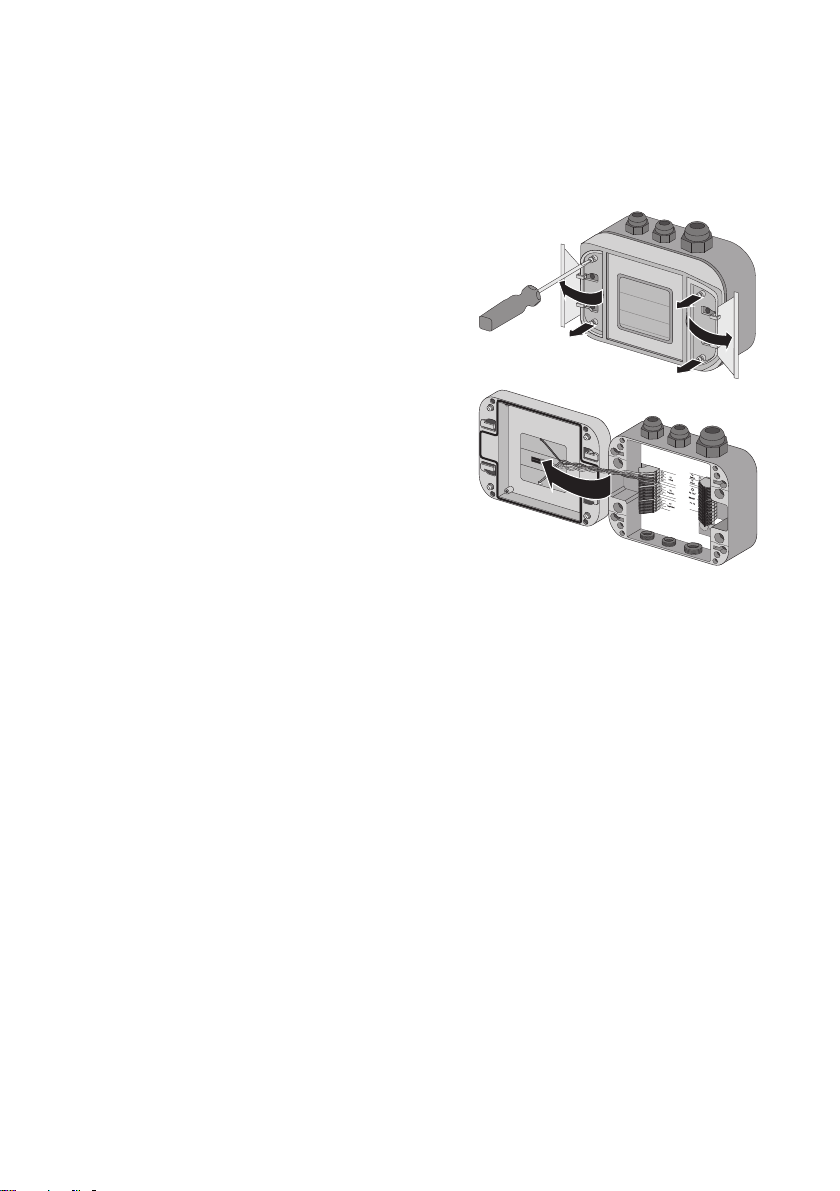
1. Using the notches as a guide, open the side flaps of
the Sunny SensorBox
2. Loosen the screws in the corners of the Sunny
SensorBox.
3. Open the enclosure lid up towards the left. The lid is
connected to the lower shell by hooks.
☑ The Sunny SensorBox is open.
8.2 Closing the Sunny SensorBox
1. Check the sealing of the Sunny SensorBox enclosure before closing the lid on the lower
enclosure shell. If the sealing of the enclosure has become porous over time, make sure you
replace the enclosure gaskets (see section 9.4”Replacing the Gaskets of the Sunny SensorBox”
(page63)).
2. Close the lid of the Sunny SensorBox on the lower enclosure shell.
3. Initially turn the screws of the enclosure lid a little to the left, until the screws fall into the first turn
of the thread.
4. Insert screws into the lower enclosure shell and turn until finger tight (torque: 1 Nm).
5. Close the side flaps of the Sunny SensorBox.
☑ The Sunny SensorBox is closed.
Installation Guide Sensorbox-IEN100914 61
Page 62
Maintenance and Care SMA Solar Technology AG
9 Maintenance and Care
9.1 Maintenance
Inspect the Sunny SensorBox and the RS485 Power Injector or SMA Power Injector with Bluetooth
for signs of external damage or dirt on a regular basis.
If the integrated PV cell of the Sunny SensorBox or the sensors are dirty (e.g., from leaves or bird
droppings), the data they provide will be incorrect. Clean the Sunny SensorBox and sensors at regular
intervals. Information on how to clean the Sunny SensorBox is provided in section 9.5”Care”
(page64).
If a component becomes defective or no longer complies with safety standards, then replace the
device, the sensors or the cable.
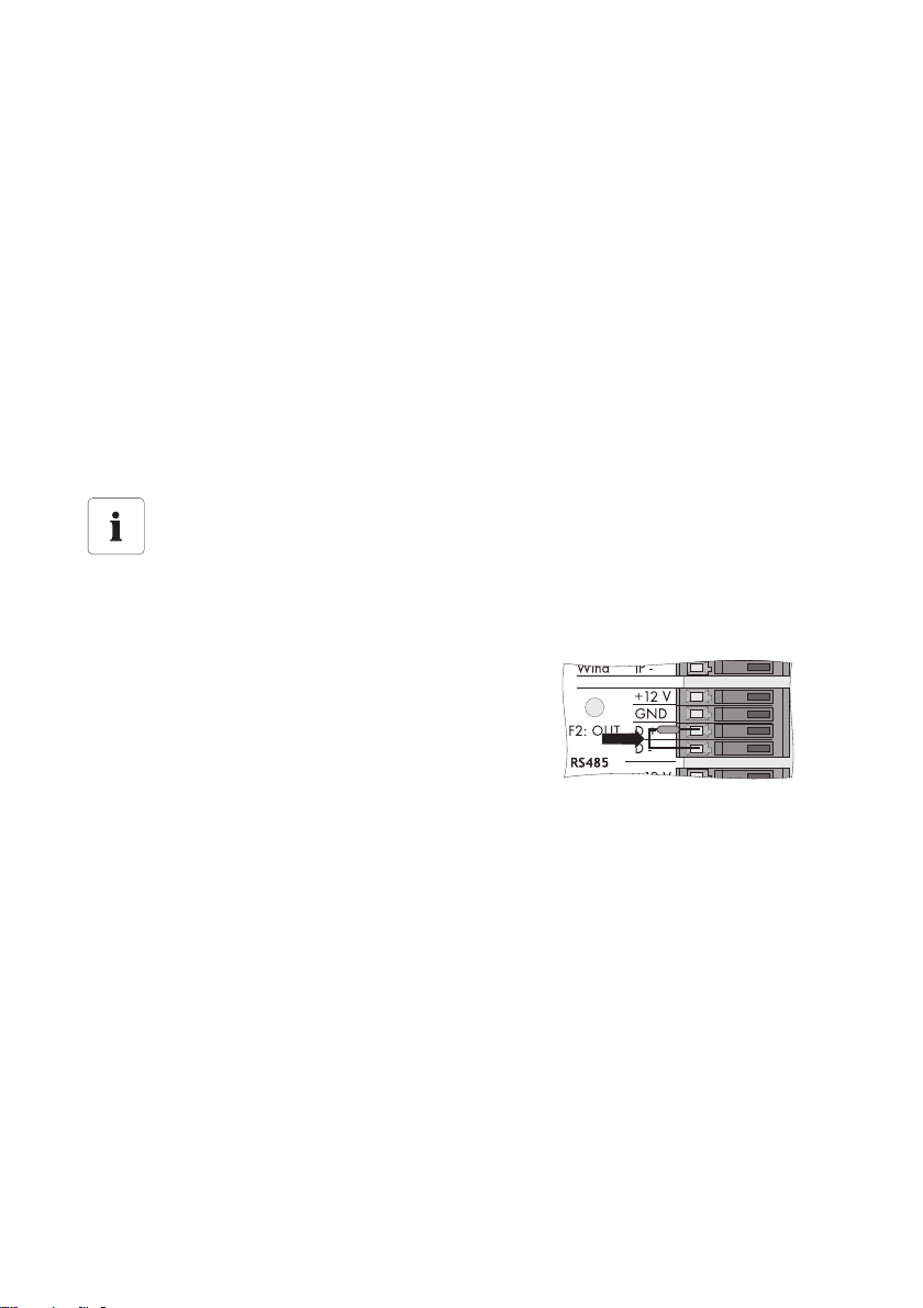
9.2 Terminating the RS485 Bus on the Sunny SensorBox
Termination of the RS485 communication bus
Refer to the RS485 cabling plan poster for the termination of an RS485 communication
bus.
Termination is carried out by means of a termination resistor. The termination resistor is already
installed upon delivery.
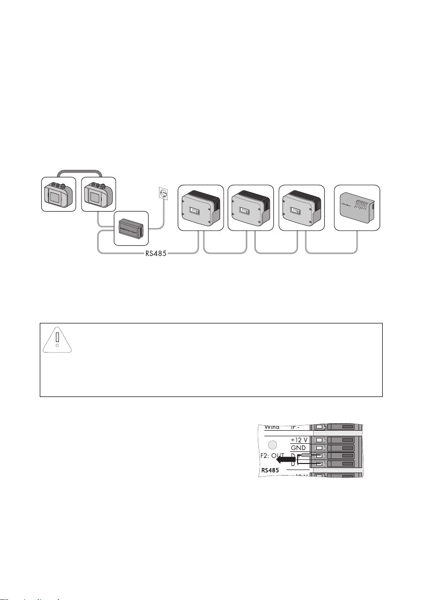
1. Connect the termination resistor on the
"RS485 F2: OUT" terminal to the "D+" and "D–"
terminals.
☑ The Sunny SensorBox is terminated.
62 Sensorbox-IEN100914 Installation Guide
Page 63
SMA Solar Technology AG Maintenance and Care
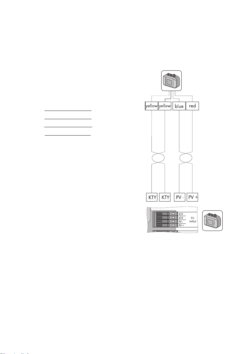
9.3 Connecting the Integrated Solar Radiation Sensor
The integrated solar radiation sensor in the lid of the Sunny SensorBox is already connected upon
delivery. You can reconnect the integrated solar radiation sensor if you previously disabled it.
To connect the sensor, proceed as follows:
1. Remove the plug-in power supply unit of the RS485
Power Injector from the power outlet.
2. Open the Sunny SensorBox (see page 61).
3. Connect the sensor on the "F5: IntSol" terminal of the
Sunny SensorBox.
KTY yellow cable
KTY yellow cable
PV- blue cable
PV+ red cable
4. Close the Sunny SensorBox (see page 61).
☑ The integrated solar radiation sensor is now
connected to the Sunny SensorBox.
9.4 Replacing the Gaskets of the Sunny SensorBox
The enclosure sealing and the gaskets of the cable glands in the Sunny SensorBox will become porous
over time. If, after a lengthy period of operation, you open and close the Sunny SensorBox or make
adjustments to the cable glands, then the gaskets and seals will no longer serve their intended
purpose.
Replace the gaskets if you open the Sunny SensorBox (e.g., for retrofitting needs) for the first time in
five years of operation. Be sure to order a new gasket set for the Sunny SensorBox before beginning
any maintenance work.
To replace the gaskets of the Sunny SensorBox, proceed as follows:
1. Open the Sunny SensorBox (see page 61).
2. Remove the relevant cable from the cable gland in the reverse order in which it is connected.
Installation Guide Sensorbox-IEN100914 63
Page 64

Maintenance and Care SMA Solar Technology AG
3. Unscrew the old cable gland from the
Sunny SensorBox.
4. Place the appropriate gasket ring onto the thread
of the new cable gland.
NOTICE!
Damage to Sunny SensorBox from water seeping in.
Tightening the cable gland may cause the gasket ring to become damaged or loose its
proper threading position in the cable gland. The Sunny SensorBox will no longer be
watertight as a result.
• Make sure the gasket ring is seated properly.
5. Screw the cable gland into the Sunny SensorBox until finger tight (torque: 0.8 Nm).
6. Remove the porous rubber seal in the Sunny SensorBox lid and replace it with the new one.
7. Reinsert the relevant cable into the enclosure and make all the necessary connections.
8. Make sure the cable opening seals of the cable gland are seated properly.
9. Screw the lock nuts onto the cable gland until finger tight to fix the cable (torque: 0.8 Nm).
10. Close the Sunny SensorBox (see page 61).
☑ The gaskets of the cable gland have been replaced.
9.5 Care
Us e a s oft and mois t cl oth to c lea n th e Su nny Sens orB ox a nd t he R S48 5 Po wer Injec tor or S MA Power
Injector with Bluetooth. Make sure the cloth is made of scratch-free material so as to avoid damaging
the surface of the enclosure. If there is a considerable amount of dirt, you can also use a mild, nonabrasive and non-corrosive cleaning agent.
64 Sensorbox-IEN100914 Installation Guide
Page 65

SMA Solar Technology AG Decommissioning
10 Decommissioning
10.1 Dismantling the Sunny SensorBox
1. Remove the plug-in power supply unit of the RS485 Power Injector or SMA Power Injector with
Bluetooth from the power outlet or disconnect the alternate power source of the SMA Power
Injector with Bluetooth.
2. Remove all cable connections in the Sunny SensorBox:
– RS485 Power Injector: Disconnect the Sunny SensorBox and RS485 Power Injector
cables in the reverse order in which they are connected. Make sure the RS485
communication bus has been terminated.
– SMA Power Injector with Bluetooth: Disconnect the Sunny SensorBox and SMA Power
Injector with Bluetooth cables in the reverse order in which they are connected.
3. Dismantle the Sunny SensorBox in the reverse order in which it is mounted.
☑ The Sunny SensorBox is now dismantled.
10.2 Dismantling the RS485 Power Injector
NOTICE!
!
Damage to wall bracket due to careless cable removal
• Hold the RS485 Power Injector firmly in place when connecting or disconnecting the
power cable or plug connector. If not held securely, the device may pop out and
cause damage or even destroy the wall mounting bracket.
If you want to retrofit or upgrade an existing PV system, you first need to modify its
configuration so that the baud rate of the Sunny SensorBox is set at 1,200 Bd. You can
now install the SMA Power Injector with Bluetooth and the Sunny SensorBox.
1. Remove all the cable connections of the RS485 Power Injector.
2. Detach the RS485 Power Injector from the wall mounting bracket as shown below.
3. Unscrew the wall mounting bracket from the wall.
☑ The RS485 Power Injector is now dismantled.
Installation Guide Sensorbox-IEN100914 65
Page 66

Decommissioning SMA Solar Technology AG
1
2
2
1
10.3 Dismantling the SMA Power Injector with Bluetooth
NOTICE!
Damage to wall bracket due to careless cable removal
• Hold the SMA Power Injector with Bluetooth firmly in place when connecting or
disconnecting the power cable or plug connector. If not held securely, the device
may pop out and cause damage or even destroy the wall mounting bracket.
1. Remove all the cable connections of the SMA Power Injector with Bluetooth.
2. Detach the SMA Power Injector with Bluetooth from the mounting bracket as illustrated below.
Removing the SMA Power Injector with Bluetooth from the Wall
Removing the SMA Power Injector with Bluetooth from the Top--hat Rail
3. Unscrew the bracket from the wall.
☑ The SMA Power Injector with Bluetooth is now dismantled.
10.4 Dismantling the Sensors
If you want to dismantle the ambient temperature sensor, module temperature sensor or
solar radiation sensor and remove all the connections in the Sunny SensorBox, the Sunny
WebBox will display unrealistic data for these sensors.
• Disconnect the sensor cables in the reverse order in which they are connected.
66 Sensorbox-IEN100914 Installation Guide
Page 67

SMA Solar Technology AG Decommissioning
10.5 Packaging the Sunny SensorBox and Sensors
For reshipment, use a transport-secure packaging - if possible the original packaging.
10.6 Disposing of the Sunny SensorBox and Sensors
At the end of their service life, Sunny SensorBoxes and their components can be disposed of in
compliance with all current and local regulations regarding electronic waste disposal or, alternatively,
sent back to SMA Solar Technology AG with shipping paid by the sender and labeled "ZUR
ENTSORGUNG" (for disposal).
Installation Guide Sensorbox-IEN100914 67
Page 68

Troubleshooting SMA Solar Technology AG
11 Troubleshooting
If a particular error does not appear in this section, call the SMA Serviceline and have the
information listed in section 15”Contact” (page81) on hand.
11.1 Sunny SensorBox
Problem Cause Rectification
The Sunny SensorBox
cannot be found.
The LED of the Sunny
SensorBox fails to
light up within 60
seconds of being
connected to the
power supply.
The LED of the Sunny
SensorBox flashes
yellow every second.
Sunny Explorer or
Sunny WebBox with
Bluetooth displays the
wrong device.
The "TmpAmb" display
value shows one of
the following values
continuously: –
273.15 °C, 0 K, –
459.67 °F.
The RS485 bus is not
terminated on the Sunny
SensorBox.
The Sunny SensorBox
does not have power.
Firmware error. Contact the SMA Serviceline.
More than one Sunny
SensorBox is connected to
the SMA Power Injector
with Bluetooth.
The ambient temperature
sensor is not connected.
Terminate the RS485 bus on the
Sunny SensorBox.
For information on RS485 cabling, refer to the
RS485 cabling plan poster.
Make sure the plug-in powe r sup ply uni t of the
RS485 Power Injector or SMA Power Injector
with Bluetooth is connected to a power outlet.
Check the connection between the RS485
Power Injector or SMA Power Injector with
Bluetooth and the Sunny SensorBox.
Connect only one Sunny SensorBox to the
SMA Power Injector with Bluetooth.
Connect the ambient temperature sensor to
the Sunny SensorBox.
Check the cabling.
68 Sensorbox-IEN100914 Installation Guide
Page 69

SMA Solar Technology AG Troubleshooting
Problem Cause Rectification
Unrealistic readings
from the ambient
temperature sensor
are displayed.
The sensor is not
connected properly.
The sensor cable is
damaged.
The sensor is damaged or
dirty.
The sensor has been
deactivated and the
Make sure the sensor is connected to the right
terminal on the Sunny SensorBox.
Inspect the cable for signs of damage and
replace if necessary.
Clean the sensor.
Replace defective sensors.
Plug the resistor into the connection terminal of
the ambient temperature sensor.
resistor is no longer
connected to the Sunny
SensorBox.
Unrealistic readings
from the anemometer
are displayed.
Unrealistic readings
from the integrated
solar radiation sensor
are displayed.
The requisite cable length
was ignored.
The sensor is not
connected properly.
The sensor cable is
damaged.
The sensor is damaged or
dirty.
The requisite cable length
was ignored.
The sensor is not
connected properly.
The sensor cable is
damaged.
The sensor is damaged or
dirty.
Check the cable length. Adhere to the cable
length specified in the sensor manual.
Make sure the sensor is connected to the right
terminal on the Sunny SensorBox.
Inspect the cable for signs of damage and
replace if necessary.
Clean the sensor.
Replace defective sensors.
Check the cable length. Adhere to the cable
length specified in the sensor manual.
Make sure the sensor is connected to the right
terminal on the Sunny SensorBox.
Inspect the cable for signs of damage and
replace if necessary.
Clean the sensor.
Replace defective sensors.
11.2 RS485 Power Injector
Problem Cause Rectification
The "Power" LED on
the RS485 Power
Injector does not light
up.
Installation Guide Sensorbox-IEN100914 69
The RS485 Power Injector
does not have power.
Make sure the plug-in powe r sup ply uni t of the
RS485 Power Injector is connected to a
power outlet.
Page 70

Troubleshooting SMA Solar Technology AG
11.3 SMA Power Injector with Bluetooth
Problem Cause Rectification
Only the "RDY" LED of
the SMA Power
Injector with Bluetooth
is on.
The "RDY" LED of the
SMA Power Injector
with Bluetooth does
not light up.
The "RDY" LED of the
SMA Power Injector
with Bluetooth flashes.
The "COM" LED of the
SMA Power Injector
with Bluetooth fails to
flash.
The Sunny SensorBox is
not connected.
The SMA Power Injector
with Bluetooth does not
have power.
The supply voltage is too
low.
The supply voltage is
borderline.
Incorrect cabling - the
wires of the RS485
communication cable
were either inverted
during connection or not
connected at all.
Connect one Sunny SensorBox to the SMA
Power Injector with Bluetooth.
Make sure the plug-in powe r sup ply uni t of the
SMA Power Injector with Bluetooth is
connected to a power outlet or the alternate
power source is running.
Replace the defective devices.
Check the alternate power source. Observe
the requirements for the alternate power
source (see page 60).
Improve the power supply of the alternate
power source in one of the following ways:
•Shorten the cable.
• Use cables with a larger cross-section.
Use the plug-in power supply unit that is
provided as an accessory for the SMA Power
Injector with Bluetooth (see 58).
Check the cabling.
70 Sensorbox-IEN100914 Installation Guide
Page 71

SMA Solar Technology AG Parameters
12 Parameters
12.1 RS485 Power Injector
The communication product helps you to display the parameter list o n yo ur c omp ute r. T he l ist pro vid es
display values and configurable parameters. Display values such as the serial number (SN) are read
only. Configurable parameters such as the unit of temperature (TmpUnit) can be changed.
12.1.1 Display Values
Sunny SensorBox
Name Description
SN serial number of the Sunny SensorBox
FwVer firmware version of the Sunny SensorBox
HwVer hardware version of the Sunny SensorBox
OpTm operating hours of the Sunny SensorBox since initial startup
Internal Solar Radiation Sensor
Name Description
IntSolIrr current level of solar radiation in W/m²
Module Temperature Sensor
*
Name Description
TmpMdul C module temperature in °C
TmpMdul K module temperature in K
TmpMdul F module temperature in °F
* If no module temperature sensor is connected, absolute zero is displayed (–273.15 °C, 0 K, –459.67 °F).
Ambient Temperature Sensor
Name Description
TmpAmb C ambient temperature in °C
TmpAmb K ambient temperature in K
TmpAmb F ambient temperature in °F
* If no ambient temperature sensor is connected, absolute zero is displayed (–273.15 °C, 0 K, –459.67 °F).
Installation Guide Sensorbox-IEN100914 71
*
Page 72

Parameters SMA Solar Technology AG
Anemometer
*
Name Description
WindVel m/s wind velocity in m/s
WindVel km/h wind velocity in km/h
WindVel mph wind velocity in mph
* If no anemometer is connected or the wind velocity exceeds the measurement range, "0" is displayed in these channels.
12.1.2 Configurable Parameters
Name Description Value / range Explanation Default
value
DevNam device name Text allocation of a user-defined
device name
TmpUnit unit of temperature °C degrees Celsius °C
KKelvin
°F degrees Fahrenheit
WindUnit unit for wind velocity m/s m/s
km/h
mph
DevRs Sunny SensorBox
reset
RS485DI response delay of the
Sunny SensorBox to
the RS485 bus;
this parameter is only
visible if you are
logged in as an
"installer" in the
communication device
0 ms … 255 ms for reset, enter "1" and save;
the specified parameter will
not be added and the LED in
the Sunny SensorBox remains
off for 60 seconds
0 ms … 1.000 ms if you are using a Sunny Boy
Control/Plus, this parameter
mu st be se t to "20 0 ms"; if you
are using a Sunny WebBox,
the response delay can be
reduced to "10 ms".
200 ms
0
72 Sensorbox-IEN100914 Installation Guide
Page 73

SMA Solar Technology AG Parameters
Name Description Value / range Explanation Default
value
SmaNetBd value for baud rate 300 baud communication problems
600 baud
1,200 baud
2,400 baud
4,800 baud
9,600 baud
19,200 baud
38,400 baud
57,600 baud
115,200 baud
230,400 baud
may occur if some devices are
unable to achieve 1,200
baud, which is the standard
SMA baud rate setting Adjust
the baud rate if necessary.
1,200 baud
12.2 SMA Power Injector with Bluetooth
The display values and parameter list are displayed on the web interface of the Sunny WebBox with
Bluetooth and in Sunny Explorer. Display values are read only.
12.2.1 Display Values
Name Description
Status general values that describe the status of the device; the status of other
System communication all values that define communication between the communication devices
Meteorology includes all measured values of the connected sensors (e.g., temperature,
*The display values are determined by the respective country settings of the communication products.
*
components in the device (e.g., modems) are not listed here
and the PV system
radiation, wind velocity).
12.2.2 Configurable Parameters
Name Description Value / range Explanation
DevNam device name Text allocation of a user-defined device name
Installation Guide Sensorbox-IEN100914 73
Page 74
Technical Data SMA Solar Technology AG
13 Technical Data
13.1 Sunny SensorBox
Mechanical Data
Width x Height x Depth 120 mm x 50 mm x 90 mm
Weight 500 g
Way of mounting mounting plate / roof bracket
Mounting location outdoors
Power Supply
Power supply via RS485 Power Injector /
SMA Power Injector with Bluetooth
Power consumption < 1 W
Ambient Conditions
Ambient temperature –25 °C … +70 °C
Protection rating
*
Protection rating according to DIN EN 60529
*
IP65
Communication
Communication RS485 (RS485 Power Injector) /
Bluetooth (SMA Power Injector with Bluetooth)
Integrated Solar Radiation Sensor
PV cell type PV cell, amorphous silicon (aSi)
Measurement range 0 W/m² … 1,500 W/m²
Measurement accuracy ± 8 %
Resolution 1 W/m²
Module Temperature Sensor
Measuring resistor platinum sensor (PT100)
Protection rating
Cable length
Measurement range –20 °C … +110 °C
Measurement accuracy ± 0.5 °C
Resolution 0.1 °C
*
Protection rating according to DIN EN 60529
**
Connection cable with two-wire technology
*
**
IP62
2.5 m
74 Sensorbox-IEN100914 Installation Guide
Page 75
SMA Solar Technology AG Technical Data
13.2 RS485 Power Injector
Mechanical Data
Width x Height x Depth 105 mm x 55 mm x 30 mm
Weight 80 g
Way of mounting wall mounting, tabletop device
Mounting location indoors
Power Supply
Power supply via plug-in power supply
Power consumption
Maximum number of Sunny SensorBoxes that
*
<5W
5
can be operated
*
With five Sunny SensorBox devices
Ambient Conditions
Ambient temperature –20 °C … +65 °C
Relative air humidity 5 % … 95 %, non condensing
Protection rating
*
Protection rating according to DIN EN 60529
*
IP20
Communication
Maximum communication range of RS485 1,200 m
Other
Maximum cable length to the last Sunny
SensorBox in the RS485 bus
150 m
Installation Guide Sensorbox-IEN100914 75
Page 76
Technical Data SMA Solar Technology AG
13.3 SMA Power Injector with Bluetooth
Mechanical Data
Width x Height x Depth 142 mm x 40 mm x 76 mm
Weight 144 g
Way of mounting wall mounting / top-hat rail mounting
Mounting location indoors
Power Supply
Po wer su ppl y v ia pl ug- in p owe r su ppl y / p owe r module / alt ern ate
power source
Power module / alternate power source 2-pole socket
Typical power consumption 0.8 W
Maximum power consumption 1.5 W
Maximum number of Sunny SensorBoxes that
can be operated
Input voltage of power module / alternate power
source
typically 12 V … 24 V AC ± 10 %, 50 Hz /
60 Hz or typically 12 V … 24 V DC ± 20 %
Ambient Conditions
Ambient temperature during operation –20 °C … +65 °C
Ambient temperature during storage and
transport
Relative air humidity 5 % … 95 %, non-condensing
Protection rating
*
Elevation above mean sea level (AMSL) 0 m … 3,000 m
*
Protection rating according to DIN EN 60529
–40 °C … +70 °C
1
IP20
Communication
Maximum free field communication range of
Bluetooth
*
Can be extended with SMA Bluetooth Repeater.
*
100 m
Other
Maximum cable length to the last Sunny
SensorBox
Maximum number of nodes in a Bluetooth
network
76 Sensorbox-IEN100914 Installation Guide
150 m
50
Page 77
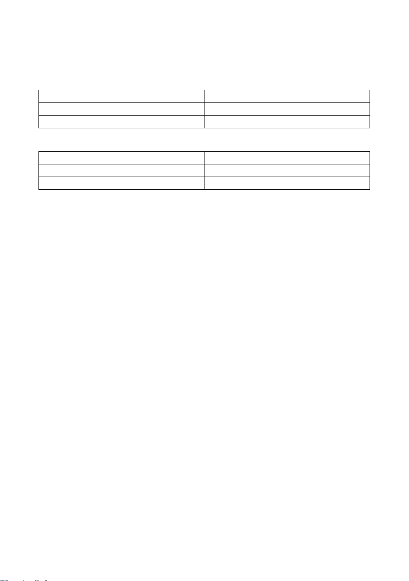
SMA Solar Technology AG Technical Data
13.4 Plug-in Power Supply
Mechanical Data
Width x Height x Depth 108 mm x 58 mm x 34 mm
Weight 300 g
Mounting location indoors
Power Supply
Input voltage 100 V … 240 V AC, 50 Hz / 60 Hz
Output voltage 12 V DC ± 2 %
Maximum output current 2.5 A
Installation Guide Sensorbox-IEN100914 77
Page 78
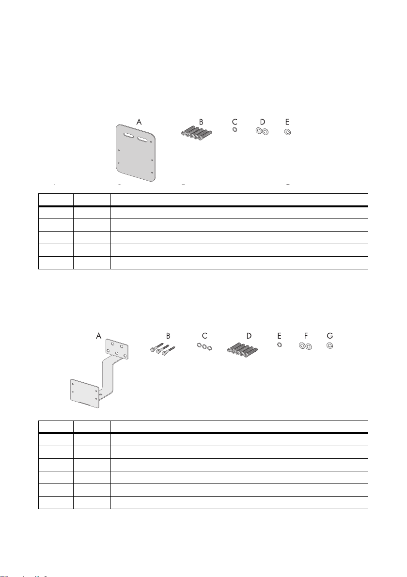
Accessories SMA Solar Technology AG
14 Accessories
14.1 Mounting Plate
SMA order number: Monplat-Ssensor
Position Quantity Designation
A 1 Mounting plate
B5 M4 hexagonal screws
C 1 M4 contact washer
D2 Washers
*
E1 Locking washer
*
Pre-mounted on delivery.
14.2 Roof Bracket
SMA order number: Roofan-Ssensor
*
*
*
Position Quantity Designation
A 1 Roof bracket
B 3 Hexagonal wood screws
C 3 Washers for hexagonal wood screws
D5 M4 hexagonal screws
E 1 M4 contact washer
F2 Washers
*
Pre-mounted on delivery.
78 Sensorbox-IEN100914 Installation Guide
*
*
*
Page 79
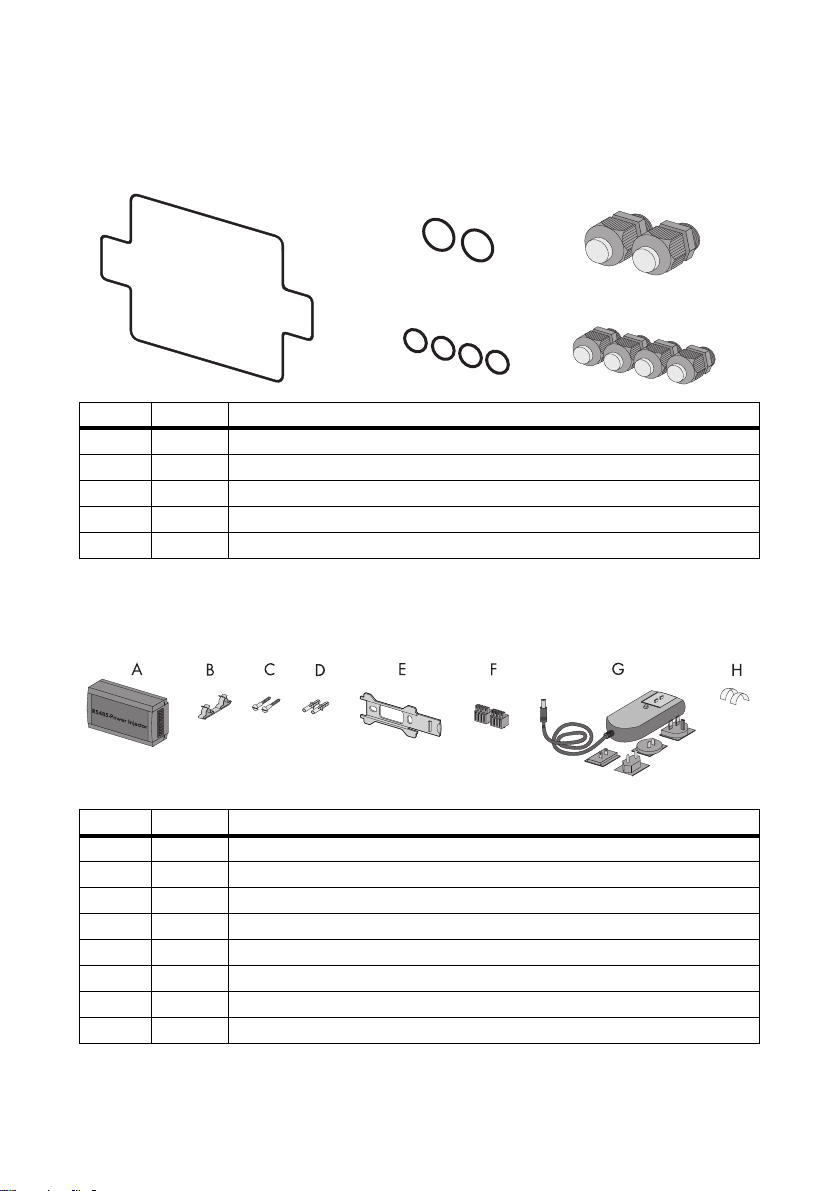
SMA Solar Technology AG Accessories
A
B
C
D
E
14.3 Gasket Set for Sunny SensorBox
SMA order number: Sealkit-Ssensor
Position Quantity Designation
A 1 Enclosure seal
B 2 Gaskets of the cable glands for the RS485 communication bus
C 2 Cable glands for the RS485 communication bus
D 4 Gaskets of the cable glands for the sensors
E 4 Cable glands for the sensors
14.4 RS485 Power Injector
SMA order number: Power-Injector
Position Quantity Designation
A 1 RS485 Power Injector
B1 Shield clamp
C2 Screws
D2 Wall anchors
E 1 Wall mounting bracket
F 2 4-pole plugs
G 1 Plug-in power supply with plug adapter
H 2 Conductive adhesive films
Installation Guide Sensorbox-IEN100914 79
Page 80

Accessories SMA Solar Technology AG
14.5 SMA Power Injector with Bluetooth
SMA order number: BT-485-CON-DEV
Position Quantity Designation
A 1 SMAPowerInjectorwith Bluetooth
B 1 Bracket for wall or top-hat rail
C1 Screw
D1 Wall anchor
E 1 Plug (1 x 2 poles, 1 x 4 poles)
F 1 Power module for supplying power (scope of delivery listed in power module
installation guide) - only with order option SUNNYSENSOR-3xxx
G 1 Plug-in power supply with plug adapter - only with order option
SUNNYSENSOR-2xxx
H1 Ground cable
*
Can be found on the back of the SMA Power Injector with Bluetooth on delivery.
*
14.6 Anemometer
SMA order number: WIND-SENSOR
Position Quantity Designation
A 1 Anemometer with 3 m connection cable and screws on the bottom
B1 Mounting bracket
C2 Screws
D2 Wall anchors
E 2 Straps
80 Sensorbox-IEN100914 Installation Guide
Page 81

SMA Solar Technology AG Contact
15 Contact
If you have technical problems concerning our products, contact the SMA Serviceline. We re quire t he
following information in order to provide you with the necessary assistance:
• Type of inverters and serial number
• Serial number and firmware version of the communication device
• Serial number and firmware version of the Sunny SensorBox
SMA Solar Technology AG
Sonnenallee 1
34266 Niestetal, Germany
www.SMA.de
SMA Serviceline
Inverters: +49 561 9522 1499
Communication: +49 561 9522 2499
Fax: +49 561 9522 4699
E-Mail: Serviceline@SMA.de
Installation Guide Sensorbox-IEN100914 81
Page 82

Page 83

SMA Solar Technology AG Legal Restrictions
The information contained in this document is the property of SMA Solar Technology AG. Publishing its content, either partially or
in full, requires the written permission of SMA Solar Technology AG. Any internal company copying of the document for the
purposes of evaluating the product or its correct implementation is allowed and does not require permission.
Exclusion of liability
The general terms and conditions of delivery of SMA Solar Technology AG shall apply.
The content of these documents is continually checked and amended, where necessary. However, discrepancies cannot be
excluded. No guarantee is made for the completeness of these documents. The latest version is available online at www.SMA.de
or from the usual sales channels.
Guarantee or liability claims for damages of any kind are excluded if they are caused by one or more of the following:
• Damages during transportation
• Improper or inappropriate use of the product
• Operating the product in an unintended environment
• Operating the product whilst ignoring relevant, statutory safety regulations in the deployment location
• Ignoring safety warnings and instructions contained in all documents relevant to the product
• Operating the product under incorrect safety or protection conditions
• Altering the product or supplied software without authority
• The product malfunctions due to operating attached or neighboring devices beyond statutory limit values
• In case of unforeseen calamity or force majeure
The use of supplied software produced by SMA Solar Technology AG is subject to the following conditions:
• SMA Solar Technology AG rejects any liability for direct or indirect damages arising from the use of software developed by
SMA Solar Technology AG. This also applies to the provision or non-provision of support activities.
• Supplied software not developed by SMA Solar Technology AG is subject to the respective licensing and liability agreements
of the manufacturer.
SMA Factory Warranty
The current guarantee conditions come enclosed with your device. These are also available online at www.SMA.de and can be
downloaded or are available on paper from the usual sales channels if required.
Trademarks
All trademarks are recognized even if these are not marked separately. Missing designations do not mean that a product or brand
is not a registered trademark.
The Bluetooth
Solar Technology AG is under license.
SMA Solar Technology AG
Sonnenallee 1
34266 Niestetal
Germany
Tel. +49 561 9522-0
Fax +49 561 9522-100
www.SMA.de
E-Mail: info@SMA.de
© 2004 to 2010 SMA Solar Technology AG. All rights reserved
®
wor d mark an d logos are registere d trademar ks owned by Bluetooth SI G, Inc. a nd any use of s uch mark s by SMA
Installation Guide Sensorbox-IEN100914 83
Page 84

4."4PMBS5FDIOPMPHZ"(
XXX4."EF
 Loading...