

Page 1

EN
SUNNY CENTRAL CP and HE-20
Sealing
Additional sheet
1 Validity
The sealing kit serves as verification as to whether the inverter has been subject to unauthorized
opening and as protection against manipulation. The sealing kit can be used for the following inverter
types:
• Sunny Central 500CP (SC 500CP-10)
• Sunny Central 630CP (SC 630CP-10)
• Sunny Central 720CP (SC 720CP-10)
• Sunny Central 760CP (SC 760CP-10)
• Sunny Central 800CP (SC 800CP-10)
• Sunny Central 500HE (SC 500HE-20)
• Sunny Central 630HE (SC 630HE-20)
• Sunny Central 720HE (SC 720HE-20)
• Sunny Central 760HE (SC 760HE-20)
• Sunny Central 800HE (SC 800HE-20)
This document describes the actions necessary in order to seal an inverter.
2Scope of Delivery
Check the delivery for completeness and for any external damage. Co nta ct y our ret ail er if the del ive ry
is incomplete or you find any damage.
Position Quantity Description
A 20*
* 16 sealing screws are necessary for inverters of the Sunny Central CP production series and 14 sealing screws are
necessary for inverters of the Sunny Central HE-20 production series. The remaining sealing screws are spares.
Plomb-BB-IEN112920 | Version 2.0
Sealing screw
Page 2
SMA Solar Technology AG Sealing
8"3/*/(
3Sealing
3.1 Requirements for sealing
Risk of death due to electric shock when live component parts of the central inverter are
touched!
• Disconnect the central inverter before sealing.
☐ The sealing wires are provided by the customer.
☐ The seals are provided by the electric utility company.
☐ The central inverter is disconnected.
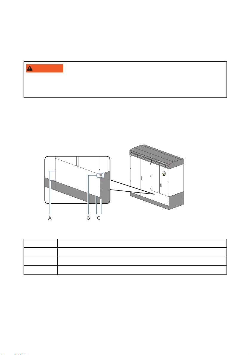
3.2 Sealing the front side of the connection cabinet
Figure1: Positions of the screws for sealing (in this example a Sunny Central 500CP)
Position Description
A 1st pair of screws
B 2nd pair of screws
C 3rd pair of screws
1. Remove the screws from the front and side panels using a Torx screwdriver. Put the washers
safely to one side.
2. Insert the sealing screws with washers and tighten (torque 6 Nm).
3. Thread the sealing wire through the screw pairs.
4. Seal the sealing wire using the seal.
Additional sheet Plomb-BB-IEN112920 2/6
Page 3

SMA Solar Technology AG Sealing
3.3 Sealing the rear side of the connection cabinet
3.3.1 Sealing the rear side of the connection cabinet on an outdoor installation
Figure2: Positions of the screws for the sealing in Sunny Centrals of the CP production series
Position Description
A 1st pair of screws
B 2nd pair of screws
C 3rd pair of screws
1. Remove the screws from the rear and side panels using a Torx screwdriver. Put the washers
safely to one side.
2. Insert the sealing screws with washers and tighten (torque 6 Nm).
3. Thread the sealing wire through the screw pairs.
4. Seal the sealing wire using the seal.
Additional sheet Plomb-BB-IEN112920 3/6
Page 4

SMA Solar Technology AG Sealing
3.3.2 Sealing the rear side of the connection cabinet on a station installation
If you have installed central inverters of the CP- and HE-20 production series in a station, the rear
screws on the rear side of the connection cabinet are not accessible.
Figure3: Positions of the screws for sealing in a station installation (using the ex ample of a Sunny Central of the
HE-20 production series)
1. If the screws on the rear panel are accessible, remove the screws from the rear and side panels
using a Torx screwdriver. Put the washers safely to one side.
2. If the screws on the rear panel are not accessible, only remove the screws from the side panel
using a Torx screwdriver. Put the washers safely to one side.
3. Insert the sealing screws with washers and tighten (torque 6 Nm).
4. Thread the sealing wire through the screw pairs.
5. Seal the sealing wire using the seal.
Additional sheet Plomb-BB-IEN112920 4/6
Page 5

SMA Solar Technology AG Sealing
3.4 Sealing the protective cover of the AC contactor
Figure4: Positions of the screws for sealing in the protective cover of the AC contactor
Position Description
A Screw and switch cabinet frame
B 2nd pair of screws
C 3rd pair of screws
D Screw and switch cabinet frame
1. Open the inverter cabinet.
2. Remove the protective cover screws using a hexagon-socket wrench.
Put the washers safely to one side.
3. Insert the sealing screws with washers and tighten (torque 2 Nm).
4. Thread the sealing wire through the sealing screws.
Additional sheet Plomb-BB-IEN112920 5/6
Page 6

SMA Solar Technology AG Sealing
5. Thread the sealing wire through the sealing screws
and switch cabinet frame.
6. Seal the sealing wire using the seals.
7. Close the inverter cabinet.
3.5 Sealing the door locks on Sunny Centrals of the CP production series
Figure5: Positions of the door locks on Sunny Centrals of the CP production series
1. Thread the sealing wire through the door lock.
2. Seal the sealing wire using the seal.
Additional sheet Plomb-BB-IEN112920 6/6
 Loading...