

Page 1
Operating Manual
SUNNY CENTRAL COMMUNICATION CONTROLLER
SC-COM-BE-en-20 | 98-40007120 | Version 2.0 ENGLISH
Page 2

Legal Provisions SMA Solar Technology AG
Legal Provisions
The information contained in this document is the property of SMA Solar Technology AG. Publishing its content, either partially or in full, requires the written permission of
SMA Solar Technology AG. Any internal company copying of the document for the purposes of evaluating the product or its correct implementation is allowed and does not require
permission.
SMA Manufacturer’s Warranty
You can download the current warranty conditions from the Internet at www.SMA-Solar.com.
Trademarks
All trademarks are recognised even if these are not marked separately. Missing designations do not mean that a product or brand is not a registered trademark.
The Bluetooth
SMA Solar Technology AG is under licence.
QR Code
SMA Solar Technology AG
Sonnenallee 1
34266 Niestetal
Germany
Tel. +49 561 9522-0
Fax +49 561 9522-100
www.SMA.de
E-mail: info@SMA.de
© 2004 to 2013 SMA Solar Technology AG. All rights reserved
®
word mark and logos are registered trademarks owned by Bluetooth SIG, Inc. and any use of such marks by
®
is a registered trademark of DENSO WAVE INCORPORATED.
2 SC-COM-BE-en-20 Operating Manual
Page 3

SMA Solar Technology AG Table of Contents
Table of Contents
1 Information on this Document. . . . . . . . . . . . . . . . . . . . . . . . . . . . . . . . . . . . . . . . . . . . . . . . . . . . . 5
2 Safety . . . . . . . . . . . . . . . . . . . . . . . . . . . . . . . . . . . . . . . . . . . . . . . . . . . . . . . . . . . . . . . . . . . . . . . . 7
2.1 Appropriate Usage. . . . . . . . . . . . . . . . . . . . . . . . . . . . . . . . . . . . . . . . . . . . . . . . . . . . . . . . . . . . . . . . . . . . . 7
2.2 Target Group Qualifications. . . . . . . . . . . . . . . . . . . . . . . . . . . . . . . . . . . . . . . . . . . . . . . . . . . . . . . . . . . . . . 7
2.3 Safety Precautions . . . . . . . . . . . . . . . . . . . . . . . . . . . . . . . . . . . . . . . . . . . . . . . . . . . . . . . . . . . . . . . . . . . . . 7
3 Product Description . . . . . . . . . . . . . . . . . . . . . . . . . . . . . . . . . . . . . . . . . . . . . . . . . . . . . . . . . . . . . 9
3.1 SC-COM. . . . . . . . . . . . . . . . . . . . . . . . . . . . . . . . . . . . . . . . . . . . . . . . . . . . . . . . . . . . . . . . . . . . . . . . . . . . . 9
3.2 Network Concept . . . . . . . . . . . . . . . . . . . . . . . . . . . . . . . . . . . . . . . . . . . . . . . . . . . . . . . . . . . . . . . . . . . . . 10
3.3 LEDs of the SC-COM . . . . . . . . . . . . . . . . . . . . . . . . . . . . . . . . . . . . . . . . . . . . . . . . . . . . . . . . . . . . . . . . . . 11
3.3.1 LEDs on the Enclosure . . . . . . . . . . . . . . . . . . . . . . . . . . . . . . . . . . . . . . . . . . . . . . . . . . . . . . . . . . . . . . . . . . . .11
3.3.2 LEDs on the Network Terminal. . . . . . . . . . . . . . . . . . . . . . . . . . . . . . . . . . . . . . . . . . . . . . . . . . . . . . . . . . . . . .12
3.3.3 LEDs on the Optical Fibre Terminals . . . . . . . . . . . . . . . . . . . . . . . . . . . . . . . . . . . . . . . . . . . . . . . . . . . . . . . . .13
3.4 User Interface . . . . . . . . . . . . . . . . . . . . . . . . . . . . . . . . . . . . . . . . . . . . . . . . . . . . . . . . . . . . . . . . . . . . . . . . 14
3.4.1 Design . . . . . . . . . . . . . . . . . . . . . . . . . . . . . . . . . . . . . . . . . . . . . . . . . . . . . . . . . . . . . . . . . . . . . . . . . . . . . . . .14
3.4.2 Structural View and Device View. . . . . . . . . . . . . . . . . . . . . . . . . . . . . . . . . . . . . . . . . . . . . . . . . . . . . . . . . . . .14
3.5 Type Label and Firmware Version . . . . . . . . . . . . . . . . . . . . . . . . . . . . . . . . . . . . . . . . . . . . . . . . . . . . . . . . 15
4 Logging In and Out of the User Interface . . . . . . . . . . . . . . . . . . . . . . . . . . . . . . . . . . . . . . . . . . 16
4.1 Logging Into the User Interface. . . . . . . . . . . . . . . . . . . . . . . . . . . . . . . . . . . . . . . . . . . . . . . . . . . . . . . . . . . 16
4.2 Logging Out of the User Interface . . . . . . . . . . . . . . . . . . . . . . . . . . . . . . . . . . . . . . . . . . . . . . . . . . . . . . . . 16
5 Commissioning . . . . . . . . . . . . . . . . . . . . . . . . . . . . . . . . . . . . . . . . . . . . . . . . . . . . . . . . . . . . . . . . 17
5.1 Sequence for Commissioning . . . . . . . . . . . . . . . . . . . . . . . . . . . . . . . . . . . . . . . . . . . . . . . . . . . . . . . . . . . . 17
5.2 Configuring the Network Settings on the Computer. . . . . . . . . . . . . . . . . . . . . . . . . . . . . . . . . . . . . . . . . . . 17
5.3 Setting the Language and Time . . . . . . . . . . . . . . . . . . . . . . . . . . . . . . . . . . . . . . . . . . . . . . . . . . . . . . . . . . 17
5.4 Configuring the SC-COM for the Local Network . . . . . . . . . . . . . . . . . . . . . . . . . . . . . . . . . . . . . . . . . . . . . 18
5.4.1 Information on Integrating the SC-COM into a Local Network. . . . . . . . . . . . . . . . . . . . . . . . . . . . . . . . . . . . .18
5.4.2 Configuring the SC-COM for a Static Network. . . . . . . . . . . . . . . . . . . . . . . . . . . . . . . . . . . . . . . . . . . . . . . . .18
5.4.3 Configuring the SC-COM for Dynamic Networks. . . . . . . . . . . . . . . . . . . . . . . . . . . . . . . . . . . . . . . . . . . . . . .18
5.4.4 Adjusting Network Ports . . . . . . . . . . . . . . . . . . . . . . . . . . . . . . . . . . . . . . . . . . . . . . . . . . . . . . . . . . . . . . . . . .19
5.5 Detecting Devices . . . . . . . . . . . . . . . . . . . . . . . . . . . . . . . . . . . . . . . . . . . . . . . . . . . . . . . . . . . . . . . . . . . . . 20
5.6 Parameterising the Devices. . . . . . . . . . . . . . . . . . . . . . . . . . . . . . . . . . . . . . . . . . . . . . . . . . . . . . . . . . . . . . 20
5.7 Deleting Device Descriptions . . . . . . . . . . . . . . . . . . . . . . . . . . . . . . . . . . . . . . . . . . . . . . . . . . . . . . . . . . . . 20
6 Setting the SC-COM . . . . . . . . . . . . . . . . . . . . . . . . . . . . . . . . . . . . . . . . . . . . . . . . . . . . . . . . . . . . 21
6.1 Configuring Security Settings . . . . . . . . . . . . . . . . . . . . . . . . . . . . . . . . . . . . . . . . . . . . . . . . . . . . . . . . . . . . 21
6.1.1 Changing the Password. . . . . . . . . . . . . . . . . . . . . . . . . . . . . . . . . . . . . . . . . . . . . . . . . . . . . . . . . . . . . . . . . . .21
6.1.2 Deactivating the RPC Interface . . . . . . . . . . . . . . . . . . . . . . . . . . . . . . . . . . . . . . . . . . . . . . . . . . . . . . . . . . . . .21
6.2 Configuring System Settings . . . . . . . . . . . . . . . . . . . . . . . . . . . . . . . . . . . . . . . . . . . . . . . . . . . . . . . . . . . . . 22
6.2.1 Setting the Date, Time and Time Zone. . . . . . . . . . . . . . . . . . . . . . . . . . . . . . . . . . . . . . . . . . . . . . . . . . . . . . . .22
6.2.2 Setting the Language. . . . . . . . . . . . . . . . . . . . . . . . . . . . . . . . . . . . . . . . . . . . . . . . . . . . . . . . . . . . . . . . . . . . .22
6.2.3 Entering the Operator Name. . . . . . . . . . . . . . . . . . . . . . . . . . . . . . . . . . . . . . . . . . . . . . . . . . . . . . . . . . . . . . .22
6.2.4 Resetting the SC-COM. . . . . . . . . . . . . . . . . . . . . . . . . . . . . . . . . . . . . . . . . . . . . . . . . . . . . . . . . . . . . . . . . . . .22
6.2.5 Restarting the SC-COM. . . . . . . . . . . . . . . . . . . . . . . . . . . . . . . . . . . . . . . . . . . . . . . . . . . . . . . . . . . . . . . . . . .23
Operating Manual SC-COM-BE-en-20 3
Page 4

Table of Contents SMA Solar Technology AG
6.3 Customer-Specific Settings via XML File. . . . . . . . . . . . . . . . . . . . . . . . . . . . . . . . . . . . . . . . . . . . . . . . . . . . 24
6.3.1 Uploading the custom.xml File. . . . . . . . . . . . . . . . . . . . . . . . . . . . . . . . . . . . . . . . . . . . . . . . . . . . . . . . . . . . . .24
6.3.2 Downloading the XML File custom.xml . . . . . . . . . . . . . . . . . . . . . . . . . . . . . . . . . . . . . . . . . . . . . . . . . . . . . . .24
6.3.3 Deleting the custom.xml File. . . . . . . . . . . . . . . . . . . . . . . . . . . . . . . . . . . . . . . . . . . . . . . . . . . . . . . . . . . . . . . .25
7 Managing Data. . . . . . . . . . . . . . . . . . . . . . . . . . . . . . . . . . . . . . . . . . . . . . . . . . . . . . . . . . . . . . . .26
7.1 Setting the Averaging. . . . . . . . . . . . . . . . . . . . . . . . . . . . . . . . . . . . . . . . . . . . . . . . . . . . . . . . . . . . . . . . . . 26
7.2 Setting the Data Transmission Frequency. . . . . . . . . . . . . . . . . . . . . . . . . . . . . . . . . . . . . . . . . . . . . . . . . . . 26
7.3 Setting Data Communication with Sunny Portal. . . . . . . . . . . . . . . . . . . . . . . . . . . . . . . . . . . . . . . . . . . . . . 27
7.3.1 Registering the SC-COM in Sunny Portal . . . . . . . . . . . . . . . . . . . . . . . . . . . . . . . . . . . . . . . . . . . . . . . . . . . . .27
7.3.2 Adjusting the Plant Identifier for Sunny Portal . . . . . . . . . . . . . . . . . . . . . . . . . . . . . . . . . . . . . . . . . . . . . . . . . .27
7.3.3 Deleting the Sunny Portal Buffer . . . . . . . . . . . . . . . . . . . . . . . . . . . . . . . . . . . . . . . . . . . . . . . . . . . . . . . . . . . .27
7.4 Setting Data Communication with the FTP Server . . . . . . . . . . . . . . . . . . . . . . . . . . . . . . . . . . . . . . . . . . . . 28
7.4.1 Defining Read and Write Access Rights for the FTP Server . . . . . . . . . . . . . . . . . . . . . . . . . . . . . . . . . . . . . . . .28
7.4.2 Calling up the FTP Server via the Internet Browser . . . . . . . . . . . . . . . . . . . . . . . . . . . . . . . . . . . . . . . . . . . . . .28
7.4.3 Setting and Testing the FTP Push Function . . . . . . . . . . . . . . . . . . . . . . . . . . . . . . . . . . . . . . . . . . . . . . . . . . . . .29
7.5 Making Settings for Modbus Communication . . . . . . . . . . . . . . . . . . . . . . . . . . . . . . . . . . . . . . . . . . . . . . . 30
7.5.1 Managing Modbus Profiles. . . . . . . . . . . . . . . . . . . . . . . . . . . . . . . . . . . . . . . . . . . . . . . . . . . . . . . . . . . . . . . .30
7.5.2 Changing the Unit ID. . . . . . . . . . . . . . . . . . . . . . . . . . . . . . . . . . . . . . . . . . . . . . . . . . . . . . . . . . . . . . . . . . . . .30
7.6 Downloading Data via HTTP . . . . . . . . . . . . . . . . . . . . . . . . . . . . . . . . . . . . . . . . . . . . . . . . . . . . . . . . . . . . 31
7.6.1 Downloading Data in XML Format . . . . . . . . . . . . . . . . . . . . . . . . . . . . . . . . . . . . . . . . . . . . . . . . . . . . . . . . . .31
7.6.2 Downloading Data in CSV Format . . . . . . . . . . . . . . . . . . . . . . . . . . . . . . . . . . . . . . . . . . . . . . . . . . . . . . . . . .31
7.7 Storing Data on the Memory Card . . . . . . . . . . . . . . . . . . . . . . . . . . . . . . . . . . . . . . . . . . . . . . . . . . . . . . . 33
7.7.1 Information on Saving Data on a Memory Card. . . . . . . . . . . . . . . . . . . . . . . . . . . . . . . . . . . . . . . . . . . . . . . .33
7.7.2 Inserting the Memory Card . . . . . . . . . . . . . . . . . . . . . . . . . . . . . . . . . . . . . . . . . . . . . . . . . . . . . . . . . . . . . . . .33
7.7.3 Enabling and Disabling Data Storage on the Memory Card . . . . . . . . . . . . . . . . . . . . . . . . . . . . . . . . . . . . . .33
7.8 Determining Available Memory Space . . . . . . . . . . . . . . . . . . . . . . . . . . . . . . . . . . . . . . . . . . . . . . . . . . . . 34
7.9 Displaying and Downloading the Event Report . . . . . . . . . . . . . . . . . . . . . . . . . . . . . . . . . . . . . . . . . . . . . . 34
7.10 Activating Alert in the Event of a Fault . . . . . . . . . . . . . . . . . . . . . . . . . . . . . . . . . . . . . . . . . . . . . . . . . . . . . 35
8 Updating the Firmware . . . . . . . . . . . . . . . . . . . . . . . . . . . . . . . . . . . . . . . . . . . . . . . . . . . . . . . . .36
8.1 Information on Updating the Firmware . . . . . . . . . . . . . . . . . . . . . . . . . . . . . . . . . . . . . . . . . . . . . . . . . . . . 36
8.2 Enabling Automatic Firmware Updates . . . . . . . . . . . . . . . . . . . . . . . . . . . . . . . . . . . . . . . . . . . . . . . . . . . . 36
8.3 Updating the Firmware via the User Interface . . . . . . . . . . . . . . . . . . . . . . . . . . . . . . . . . . . . . . . . . . . . . . . 36
9 Troubleshooting . . . . . . . . . . . . . . . . . . . . . . . . . . . . . . . . . . . . . . . . . . . . . . . . . . . . . . . . . . . . . . .37
9.1 Error Overview. . . . . . . . . . . . . . . . . . . . . . . . . . . . . . . . . . . . . . . . . . . . . . . . . . . . . . . . . . . . . . . . . . . . . . . 37
9.2 Sending ZIP File with Service Information . . . . . . . . . . . . . . . . . . . . . . . . . . . . . . . . . . . . . . . . . . . . . . . . . . 39
10 Appendix. . . . . . . . . . . . . . . . . . . . . . . . . . . . . . . . . . . . . . . . . . . . . . . . . . . . . . . . . . . . . . . . . . . . .40
10.1 User Groups. . . . . . . . . . . . . . . . . . . . . . . . . . . . . . . . . . . . . . . . . . . . . . . . . . . . . . . . . . . . . . . . . . . . . . . . . 40
10.2 XML File custom.xml. . . . . . . . . . . . . . . . . . . . . . . . . . . . . . . . . . . . . . . . . . . . . . . . . . . . . . . . . . . . . . . . . . . 40
10.2.1 Structure of the XML File custom.xml . . . . . . . . . . . . . . . . . . . . . . . . . . . . . . . . . . . . . . . . . . . . . . . . . . . . . . . . .40
10.2.2 Parameters and Values for the custom.xml File . . . . . . . . . . . . . . . . . . . . . . . . . . . . . . . . . . . . . . . . . . . . . . . . .41
10.3 Plant Presentation in Sunny Portal . . . . . . . . . . . . . . . . . . . . . . . . . . . . . . . . . . . . . . . . . . . . . . . . . . . . . . . . 43
10.4 Accessing the SC-COM via Sunny Portal . . . . . . . . . . . . . . . . . . . . . . . . . . . . . . . . . . . . . . . . . . . . . . . . . . 43
11 Technical Data. . . . . . . . . . . . . . . . . . . . . . . . . . . . . . . . . . . . . . . . . . . . . . . . . . . . . . . . . . . . . . . . .44
12 Contact. . . . . . . . . . . . . . . . . . . . . . . . . . . . . . . . . . . . . . . . . . . . . . . . . . . . . . . . . . . . . . . . . . . . . . .45
4 SC-COM-BE-en-20 Operating Manual
Page 5
SMA Solar Technology AG 1 Information on this Document
'$1*(5
:$5 1,1*
/05*$&
&$87,21
1 Information on this Document
Validity
This document is valid for the Sunny Central Communication Controller device type with hardware version E1 and
firmware version 1.04 or higher.
Target Group
This document is intended for skilled persons. Only persons with the appropriate skills are allowed to perform the tasks
described in this document (see Section2.2 "Target Group Qualifications", page7).
Additional Information
Additional information is available at www.SMA-Solar.com:
Document title Document type
Plant Communication in Large-Scale PV Plants - Basic Principle of Plant Communication Technical description
Setting up the Local FTP Server - Configuring a Local FTP Server for the Receipt of the PV
Plant Data via the FTP Push Function of the SUNNY WEBBOX.
SUNNY PORTAL User manual
Interface for Modbus-Communication SUNNY WEBBOX / SC-COM Modbus
SUNNY WEBBOX RPC User manual
®
Interface Technical description
Technical information
Symbols
Symbol Explanation
Indicates a hazardous situation which, if not avoided, will result in death or serious injury
Indicates a hazardous situation which, if not avoided, can result in death or serious injury
Indicates a hazardous situation which, if not avoided, can result in minor or moderate injury
Indicates a situation which, if not avoided, can result in property damage
Information that is important for a specific topic or objective, but is not safety-relevant
☐ Indicates a requirement for meeting a specific goal
☑ Desired result
✖ A problem that might occur
Operating Manual SC-COM-BE-en-20 5
Page 6
1 Information on this Document SMA Solar Technology AG
Typography
Typography Usage Example
Bold • Display messages
• Elements of a user interface
•Parameters
•Terminals
•Slots
• Elements to be selected
• Elements to be entered
> • Connects several elements to be selected • Select Plant > Detect.
[Button/Key] • Button or key to be selected or pressed • Select [Start detection].
• Select the ExlTrfErrEna parameter and set
to Off.
• Select the Parameters tab.
Nomenclature
In this manual, the Sunny Central Communication Controller is referred to as SC-COM.
Abbreviations
Abbreviation Designation Explanation
CR Carriage Return Control character starting a new line of text
CRLF Carriage Return and Line Feed CSV Comma-Separated Values File format
DHCP Dynamic Host Configuration Protocol Protocol for the dynamic assignment of IP
configurations
FTP File Transfer Protocol Network protocol for data transmission
HTTP Hypertext Transfer Protocol Protocol for data transmission via a network
IP Internet Protocol LAN Local Area Network LED Light-Emitting Diode LF Line Feed Control character signifying the end of a line of text
OF Optical Fibre RPC Remote Procedure Call Technique enabling inter-procedural communication
TCP Transmission Control Protocol Transport protocol for packet-switching in
connection-oriented networks
URL Uniform Resource Locator UPS Uninterruptible Power Supply UTC Universal Time Coordinated XML Extensible Markup Language Extensible Markup Language
6 SC-COM-BE-en-20 Operating Manual
Page 7
SMA Solar Technology AG 2 Safety
/05*$&
2 Safety
2.1 Appropriate Usage
The Sunny Central Communication Controller (SC-COM) is the central communication interface of the Sunny Central.
The SC-COM establishes the connection between the Sunny Central and the operator.
The SC-COM is used in the Sunny Central of the CP XT and the CP-US production series.
The SC-COM may only be used in accordance with the specifications of this manual. Any other use may result in personal
injury or property damage.
The data collected by the SC-COM can deviate from the data of the energy meter. The SC-COM data must not be used
for billing purposes.
The enclosed documentation is an integral part of the product.
• Read and follow the documentation to ensure proper and optimum use of the SC-COM.
• Keep the documentation in a convenient place for future reference.
2.2 Target Group Qualifications
The tasks described in this manual may be performed by qualified persons only. Skilled persons must have the following
qualifications:
• Knowledge of how the device works and is operated
• Knowledge of how to deal with the dangers and risks associated with installing and using electrical devices
• Training in the installation and commissioning of electrical devices
• Training in the installation and configuration of IT systems
• Knowledge of all applicable standards and directives
• Knowledge of and adherence to this manual and all safety precautions
Skilled persons must be authorised to modify grid-relevant parameters of connected devices.
The SC-COM distinguishes between two user groups: user and installer (see Section10.1, page40).
2.3 Safety Precautions
Damage to electronic components due to electrostatic discharge
Electrostatic discharge can damage or destroy electronic components.
• Observe the ESD safety regulations when working on the device.
• Wear suitable personal protective equipment for all work on the inverter.
• Discharge the electrostatic charge by touching uncoated, earthed enclosure parts (e.g. at the PE connection on the
doors). Only then is it safe to touch any electronic components.
Operating Manual SC-COM-BE-en-20 7
Page 8

2 Safety SMA Solar Technology AG
Data security
The SC-COM can be connected to the Internet. Note that connecting to the Internet carries the risk that unauthorised
users can gain access to and manipulate your data.
• Change the password after your first login.
• Make sure you use a high-strength password.
• Change your passwords at regular intervals.
• Protect your password from access by unauthorised users.
• Never leave slips of paper with passwords lying around.
• Set up a firewall.
• Close unnecessary network ports.
8 SC-COM-BE-en-20 Operating Manual
Page 9

SMA Solar Technology AG 3 Product Description
3 Product Description
3.1 SC-COM
The Sunny Central Communication Controller (SC-COM) is the central communication interface of the Sunny Central.
The SC-COM establishes the connection between the Sunny Central and the operator.
Figure1: Position of the SC-COM in the Sunny Central (using the Sunny Central of the CP XT production series)
Position Designation
ASC-COM
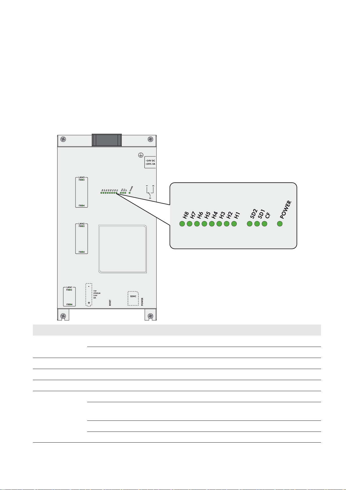
Figure2: Design of the SC-COM
Position Designation
ALEDs
B Slot for the external memory card
The SC-COM collects all data from the connected devices. The SC-COM enables monitoring, parameterisation and
remote diagnosis of the Sunny Central via computer, as well as power control of the Sunny Central by the network
operator.
Operating Manual SC-COM-BE-en-20 9
Page 10
3 Product Description SMA Solar Technology AG
The SC-COM is equipped with serial interfaces to ensure the availability of these functions. These include, for example:
• Three LAN interfaces
• RS485 interface for communication with devices used for string-current monitoring
• Interfaces for the communication with internal inverter components
These SC-COM interfaces are wired during production. When installing the Sunny Central, connect the external data
cables to the customer connection terminals in the Sunny Central.
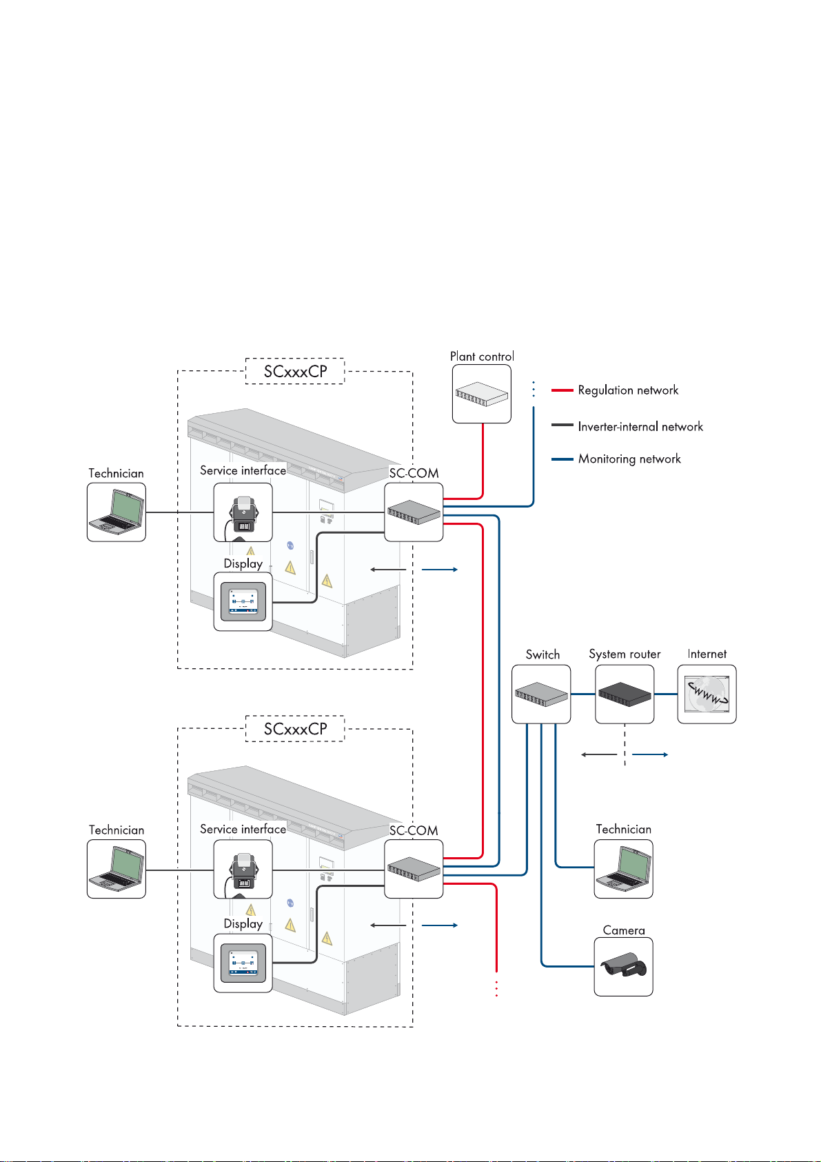
3.2 Network Concept
In order to transmit the data faster and more efficiently, the SC-COM is equipped with two additional LAN interfaces.
This enables two separate networks to be created as required. Due to the two separate networks, a faster rate of data
communication with extremely short response times is achieved. If your network has sufficient data transmission speed,
one network may be sufficient for both types of data.
Figure3: Basic principle of communication in large-scale PV power plants (example)
10 SC-COM-BE-en-20 Operating Manual
Page 11
SMA Solar Technology AG 3 Product Description
Control Network LAN2
In the control network, the specifications of the network operator for grid management, such as target values for active
and reactive power, are transmitted. The SC-COM transmits these specifications to the Sunny Central.
Monitoring Network LAN3
In the monitoring network, the data for monitoring and parameterisation is transmitted. The parameters can be configured
via an integrated web server and the user interface. The user interface also displays error messages and operating data.
3.3 LEDs of the SC-COM
3.3.1 LEDs on the Enclosure
LED designation Status Explanation
POWER Glowing green The SC-COM is supplied with voltage.
Off The SC-COM is not supplied with voltage.
SD1 Flashing green Read or write access to system drive
SD2 Flashing green Read or write access to internal data drive
CF Flashing green Read or write access to external SD card memory
H1 Flashing green The SC-COM is transmitting data to Sunny Portal/the FTP server.
Glowing green The most recent data transmission to Sunny Portal/the FTP server was
successful.
Glowing red The most recent data transmission to Sunny Portal/the FTP server failed.
Off Data transmission to Sunny Portal/the FTP server is deactivated.
Operating Manual SC-COM-BE-en-20 11
Page 12
3 Product Description SMA Solar Technology AG
LED designation Status Explanation
H2 Flashing green The SC-COM is communicating with the internally connected devices.
Glowing green Internal communication has taken place in the last five minutes.
Glowing red An error has occurred in the internal communication.
Off No internal communication has taken place in the last five minutes.
H3 Flashing red The SC-COM is starting up.
Glowing red An error has occurred at the SC-COM.
Glowing green The SC-COM is ready for operation.
H4 Glowing green An internal memory card exists and it is less than 92% full.
Glowing red The internal memory card is full and the oldest saved data is being
overwritten.
Flashing red The internal memory card is 92% full.
H5 Glowing green An external memory card exists and is less than 92% full.
Glowing red The external memory card is full.
Flashing red The external memory card is 92% full.
Off There is no external memory card.
H6 ‒ Not assigned
H7 ‒ Not assigned
H8 Flashing green Application is running.
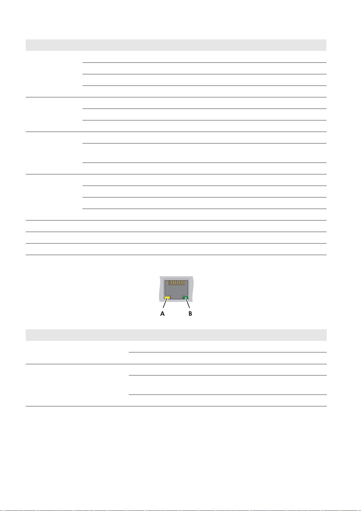
3.3.2 LEDs on the Network Terminal
Figure4: LEDs on the network terminal
Position LED Colour Status Explanation
A Speed Yellow On 100 MBit data transfer rate
Off 10 MBit data transfer rate
BLink /
Activity
Green On Connection (link) established
Flashing The SC-COM is currently transmitting or receiving data
(activity).
Off No connection established
12 SC-COM-BE-en-20 Operating Manual
Page 13
SMA Solar Technology AG 3 Product Description
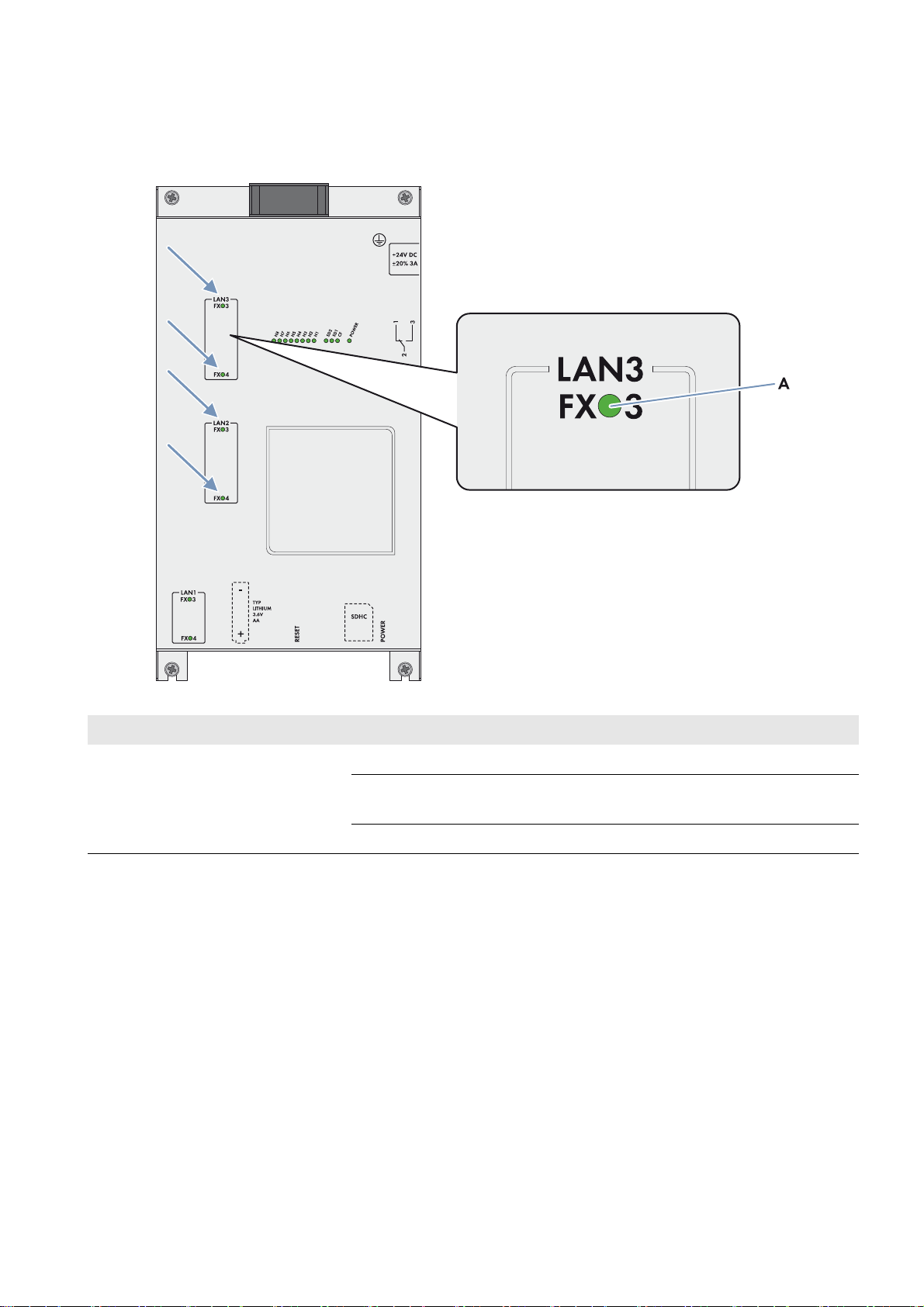
3.3.3 LEDs on the Optical Fibre Terminals
The SC-COM is also available with pre-wired optical fibre connections. If the optical fibres are connected to the splice
box of the Sunny Central, the status of the connection will be indicated by the LEDs of the SC-COM.
Figure5: LEDs for the status of the optical fibre connection
Position LED Colour Status Explanation
ALink /
Activity
Green On Connection (link) established
Flashing The SC-COM is currently transmitting or receiving data
(activity).
Off No connection established
Operating Manual SC-COM-BE-en-20 13
Page 14
3 Product Description SMA Solar Technology AG
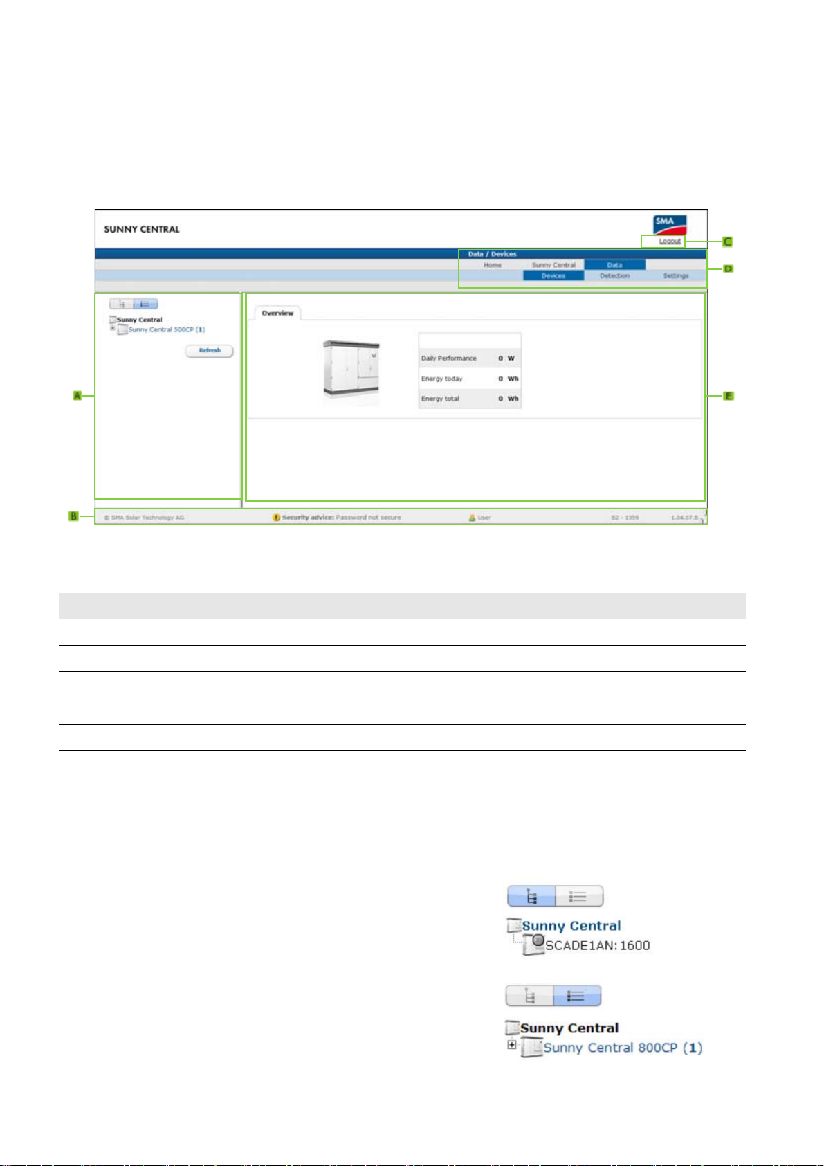
3.4 User Interface
3.4.1 Design
Via the user interface, you can set the communication of your PV plant devices, configure the Sunny Central parameters
and read off error messages and operating data.
Figure6: Design of the user interface (example)
Position Designation
A Structural view or device view
B Status bar
C Logout button
D Navigation bar
EContent area
3.4.2 Structural View and Device View
In the structural view and the device view, you can call up data of the individual devices of your PV plant. Depending on
the view, the devices are sorted and displayed differently.
Structural View
In the structural view, the user interface shows the devices in the order
in which they are connected to the data bus.
Device View
In the device view, th e user interface shows all devices sorted by device
type. Device types are, for example, all Sunny Centrals. The number
shown in parentheses indicates the number of devices of a device type.
14 SC-COM-BE-en-20 Operating Manual
Page 15
SMA Solar Technology AG 3 Product Description
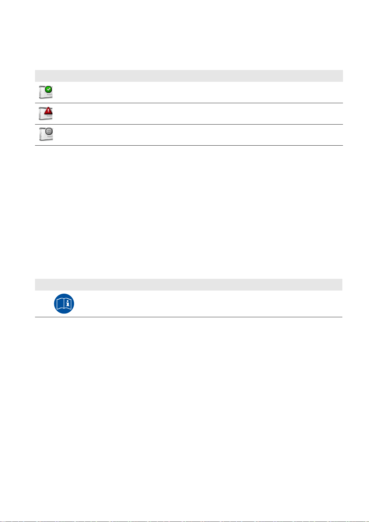
Status Icons
Depending on the status of the device communication, the device icons are displayed in the structural or device view with
various status icons.
Icon Explanation
The Sunny Central is ready for operation.
An error has occurred in the Sunny Central.
An error has occurred in the communication with the Sunny Central.
3.5 Type Label and Firmware Version
The type label provides a unique identification of the SC-COM. The type label can be found on the top of the enclosure.
You will find the following information on the type label:
•Device type
•Serial number
•Registration ID
• MAC addresses of the LAN interfaces
The firmware version can be found in the user interface of the SC-COM. The current firmware version is displayed on the
right-hand side of the status bar.
You will require the information on the type label to use the product safely and when seeking customer support from the
SMA Service Line. The type label must be permanently attached to the product.
Symbol on the Type Label
Symbol Explanation
Observe the documentation.
Observe all documentation supplied with the product.
Additional Label with Data
The type label contains a label with the serial number of the SC-COM, the registration ID and the MAC addresses of the
LAN interface. You can pull off this label and attach it to your documents or to a place where you can quickly access the
data.
Operating Manual SC-COM-BE-en-20 15
Page 16

4 Logging In and Out of the User Interface SMA Solar Technology AG
4 Logging In and Out of the User Interface
4.1 Logging Into the User Interface
Default Network Settings of the SC-COM for the Service Interface on Delivery
IP address: 192.168.100.2
Subnet mask: 255.255.255.0
Password for the "installer" and "user" user groups: sma
Identical passwords for the user groups
If your "User" password is the same as your "Installer" password, you will automatically be logged in as an installer.
• Change the default passwords for the user groups after you log in for the first time (see Section6.1 "Configuring
Security Settings", page21).
Requirement:
☐ JavaScript must be activated in the Internet browser (e.g. Internet Explorer).
Procedure:
1. Connect the laptop to the service interface of the Sunny Central.
2. Start Internet browser.
3. Enter the IP address of the SC-COM into the address bar and press the enter key.
☑ The SC-COM login page opens.
✖ The SC-COM login page does not open?
• Rectify the fault (see Section9 "Troubleshooting", page37).
4. Select the desired language in the Language field.
5. Enter the password in the Password field.
6. Select the button [Login].
4.2 Logging Out of the User Interface
Always log out from the user interface when you have finished your work. Closing your Internet browser will not log you
out. If you do not perform any action in the user interface for ten minutes, you are logged out automatically.
Procedure:
•Select [Logout].
16 SC-COM-BE-en-20 Operating Manual
Page 17

SMA Solar Technology AG 5 Commissioning
5 Commissioning
5.1 Sequence for Commissioning
Procedure See
1 Configuring the Network Settings on the Computer Section 5.2
2 Setting the Language and Time Section 5.3
3 Configuring the SC-COM for The Local Network Section 5.4
4 Detecting Devices Section 5.5
5 Parameterising the Devices Section 5.6
5.2 Configuring the Network Settings on the Computer
Before you can commission the SC-COM for the first time, you need to configure the computer based on the network
settings of the SC-COM.
Administrator rights in the operating system
To commission the SC-COM, you need to have the appropriate administrator rights to change the computer's
network settings.
• Contact your network administrator if you have any questions on administrator rights.
Procedure:
1. Note down the IP address of the computer.
2. Adapt the IP address of the computer to the address range of the SC-COM.
5.3 Setting the Language and Time
For correct display of reported events, you must set the language and time.
Procedure:
1. Log in on the user interface.
2. Set the language (see Section6.2.2, page22).
3. Set the time (see Section6.2.1, page22).
Operating Manual SC-COM-BE-en-20 17
Page 18

5 Commissioning SMA Solar Technology AG
5.4 Configuring the SC-COM for the Local Network
5.4.1 Information on Integrating the SC-COM into a Local Network
Protecting the Ethernet network from external attacks
Secure your Ethernet network from external threats by means of appropriate safety measures such as a firewall and
the allocation of secure passwords.
You can also change the network settings of the SC-COM using the XML file custom.xml (see Section6.3
"Customer-Specific Settings via XML File", page24).
5.4.2 Configuring the SC-COM for a Static Network
The SC-COM has three LAN interfaces for connected nodes.
Network Factory-set IP address
LAN1: Service interface of the Sunny Central 192.168.100.2*
LAN2: Control network 172.24.1.51
LAN3: Monitoring network 172.16.1.51
* This IP address cannot be changed.
Procedure:
1. Log in on the user interface.
2. Select Sunny Central > Settings > Network.
3. In the field IP address, enter the static IP address that you want to use to access the SC-COM in the local network.
4. Enter the subnet mask of your network in the field Subnet mask.
5. Enter the gateway IP address of your network in the field Gateway address. Usually, the IP address of the router
has to be entered here.
6. Enter the IP address of the DNS server (Domain Name System) in the field DNS server address. Usually, the IP
address of the router has to be entered here.
7. Select [Save] and [Confirm].
5.4.3 Configuring the SC-COM for Dynamic Networks
The SC-COM can obtain the network settings from a DHCP server. The IP address, subnet mask, gateway and DNS server
are automatically obtained from the DHCP server when the SC-COM is started.
Using DHCP
Before setting the SC-COM to dynamic IP address assignment, check your DHCP server. The DHCP server must
extend the lease of the assigned IP address. Do not use the DHCP server if it assigns a new IP address after the lease
has expired. DHCP servers can normally list all devices to which you have assigned an IP address. You can then
identify the SC-COM based on your MAC address. The MAC address of your SC-COM can be found on the type
label or by selecting Sunny Central > Info on the user interface.
Procedure:
1. Log in on the user interface.
2. Select Sunny Central > Settings > Network.
3. Enable DHCP in the field IP address.
4. Select [Save].
18 SC-COM-BE-en-20 Operating Manual
Page 19

SMA Solar Technology AG 5 Commissioning
5.4.4 Adjusting Network Ports
If you would like to make the SC-COM available on the Internet to allow, for example, direct access to the SC-COM via
the Sunny Portal, you must configure a port redirection in your router. The network ports of the SC-COM may need to be
adjusted.
The SC-COM uses four network ports for various services. If these ports are reserved for other applications in your
network, you can change the ports.
Adjusting the Network Ports
Make sure the SC-COM can access the web server before you change the Public virtual HTTP port setting on the
device. In most cases, the settings do not have to be changed manually, as the router automatically forwards the
queries to the correct ports via the network. Before adjusting the ports, contact your network administrator.
Requirement for setting of dynamic DNS:
☐ An account must be registered with a DynDNS provider and the login data must be available.
Procedure:
1. Log in on the user interface.
2. Select Sunny Central > Settings > Network.
3. In the field Virtual public HTTP port, enter the port enabled in the router for HTTP access. This port allows you to
access the SC-COM web server via the Internet.
4. In the field Webserver port, enter the port via which the web server of the SC-COM can be reached.
5. In the field Webservice port, enter the port via which the SC-COM sends data to Sunny Portal and loads firmware
updates.
6. If you would like to use the Modbus
®
* , activate the box Use Modbus.
Unauthorised access to the SC-COM
If you activate the Modbus protocol, unauthorised access to the SC-COM is possible. Even users without
passwords will be able to view the operating data of supported devices or change the system time of the
SC-COM.
7. In the field Modbus port, enter the port that you want the SC-COM to use when communicating via the Modbus
protocol. The default setting is port 502.
8. If you would like to use a proxy server, activate the Use proxy server box.
9. Enter the IP address and the port of the proxy server in the field Proxyserver address.
10. If you would like to use the authentication of the proxy server, activate the box Use authentication.
11. Enter the data of your proxy server in the fields User name and Password.
12. If you wish to use a dynamic DNS, activate the box Use Dyn.DNS.
13. Select the provider in the the Dyn. DNS provider field.
14. Enter the required data in the fields Domain name, User name, User password.
15. Select the button [Save].
*Modbus® is a registered trademark of Schneider Electric and is licensed by the Modbus Organization, Inc.
Operating Manual SC-COM-BE-en-20 19
Page 20

5 Commissioning SMA Solar Technology AG
5.5 Detecting Devices
During commissioning of a PV plant, all devices must be detected. If multiple interfaces (e.g. COM2 and COM3) are
used in the inverter, detection must be carried out separately for all interfaces. Devices will need to be re-detected if you:
• Have exchanged devices in your PV plant
• Have removed devices from your PV plant
• Have added devices to your PV plant
Detection of a PV plant may take several minutes
Depending on the number of devices in your PV plant, the detection process may vary in duration.
1. If the SC-COM does not indicate any progress after three minutes, cancel the search.
2. Make sure the data cable of each device is properly connected and repeat the search.
Procedure:
1. Log in on the user interface.
2. Select Data > Detect.
3. In the field Total number of devices to be detected, enter the number of devices connected to the SC-COM.
4. Select the button [Start detection].
☑ The SC-COM starts detecting all devices and displays its progress. As soon as all devices have been detected,
the SC-COM reports "### Device detection finished###".
5. Select the button [OK].
5.6 Parameterising the Devices
To change any parameters that affect device functionality, you must login as an installer. Contact your power supply
company before changing any grid-relevant parameters (see the operating manual of the Sunny Central for information
on the individual parameters).
Procedure:
1. Log into the user interface as an installer.
2. Select Data > Devices.
3. Select a device in the device view or structural view.
4. Select the Parameters tab.
5. Change the respective parameter via the Value field.
6. To adopt this value for all devices of the same type and with the same firmware version, activate the box
Save for all devices of this device type. Note that, for Sunny SensorBox devices, th e units of measure for ambient
temperature, cell temperature and wind speed must also match.
7. Select the button [Save].
☑ The SC-COM now adjusts the required value on the device(s). Once the SC-COM has changed the value, the
message "### Parameter change finished ###" appears.
8. Select the button [OK].
5.7 Deleting Device Descriptions
Whenever you replace a device in your PV plant, the descriptions of the existing devices must be deleted so that the
SC-COM can detect new devices.
Procedure:
1. Log into the user interface as an installer.
2. Select Sunny Central > Info.
3. Select [Delete device descriptions].
20 SC-COM-BE-en-20 Operating Manual
Page 21

SMA Solar Technology AG 6 Setting the SC-COM
6 Setting the SC-COM
6.1 Configuring Security Settings
6.1.1 Changing the Password
To change the password for the "installer" user group, you must be logged in as an installer.
To change the password for the "user" user group, you can be logged in as a user or an installer.
Identical passwords for the user groups
If your "User" password is the same as your "Installer" password, you will automatically be logged in as an installer.
While you enter your password, the user interface displays information on the security level of the password entered. The
SC-COM categorises passwords as very unsafe, unsafe, adequate, safe and very safe. Only select passwords with
a security quality level that is at least safe.
You can also change the password of the "installer" user group via the XML file custom.xml (see Section6.3
"Customer-Specific Settings via XML File", page24).
Procedure:
1. Log in on the user interface.
2. Select Sunny Central > Settings > Security.
3. Enter a secure password in the User password or Installer password fields and confirm it in the second field.
4. Select the button [Save].
6.1.2 Deactivating the RPC Interface
You can obtain all operating data from the SC-COM for external data processing systems using an RPC interface
(for information on the RPC interface, see the Sunny WebBox RPC user manual). On delivery, the RPC interface is
activated.
Unauthorised access to the operating data
If you activate the RPC interface, unauthorised access to the operating data is possible. Even users without
passwords can view the operating data of supported devices.
• To prevent unauthorised access to the operating data, deactivate the RPC interface.
Procedure:
1. Log into the user interface as an installer.
2. Select Sunny Central > Settings > Security.
3. Select the option Disabled in the field RPC interface.
4. Select the button [Save].
Operating Manual SC-COM-BE-en-20 21
Page 22

6 Setting the SC-COM SMA Solar Technology AG
6.2 Configuring System Settings
6.2.1 Setting the Date, Time and Time Zone
1. Log in on the user interface.
2. Select Sunny Central > Settings > System.
3. Select [Change] in the field Time zone (UTC offset).
4. Select the correct time zone in the drop-down list Time zone (UTC offset).
5. Select an option in the Automatic change from summer time to winter time field:
Option Explanation
yes Automatic change from summer time to winter time is active.
no Automatic change from summer time to winter time is not active. Date and time have to be set
manually.
6. Enter the current date in the New date field.
7. Enter the current time in the New time field.
8. Select the button [Save].
6.2.2 Setting the Language
You can also set the language of the user interface via the XML file custom.xml (see Section6.3 "Customer-Specific
Settings via XML File", page24).
Procedure:
1. Log in on the user interface.
2. Select Sunny Central > Settings > System.
3. Select the desired language in the Language field.
4. Select the button [Save].
6.2.3 Entering the Operator Name
1. Log in on the user interface.
2. Select Sunny Central > Settings > System.
3. Enter the operator name in the Operator name field.
4. Select the button [Save].
6.2.4 Resetting the SC-COM
Resetting the SC-COM will restore all settings and parameters to their default settings. If you have uploaded the file
custom.xml, the settings in this file take effect.
Data backup
• Before you reset the SC-COM, note down all settings such as network or portal settings.
• To avoid data loss, be sure to back up your PV plant data.
22 SC-COM-BE-en-20 Operating Manual
Page 23

SMA Solar Technology AG 6 Setting the SC-COM
Plant identifier in Sunny Portal
If you reset all the SC-COM settings, the SC-COM will delete all login settings for Sunny Portal. If you restart the
SC-COM after reset without changing any settings, the SC-COM will create a new plant with a new plant identifier
in Sunny Portal.
• If the SC-COM is configured to send data to the existing PV plant in Sunny Portal, adjust the identifier of the
existing PV plant (see Section7.3.2 "Adjusting the Plant Identifier for Sunny Portal", page27).
• Enter the e-mail address of a user who has administrator rights for the plant in Sunny Portal.
Procedure:
1. Log into the user interface as an installer.
2. Select Sunny Central > Info.
3. Select [Default setting].
☑ A window containing a security prompt opens.
4. Select the button [Confirm].
6.2.5 Restarting the SC-COM
In the event of disturbances in communication with the devices connected to the Sunny Central, you can restart the
SC-COM.
Procedure:
1. Log into the user interface as an installer.
2. Select Sunny Central > Info.
3. Select [Stop system].
☑ A security prompt appears.
4. Select the button [Confirm].
☑ The SC-COM is restarted.
Operating Manual SC-COM-BE-en-20 23
Page 24

6 Setting the SC-COM SMA Solar Technology AG
6.3 Customer-Specific Settings via XML File
This section describes how to configure the system and network settings using an XML file, custom.xml. To enable the
settings, the SC-COM must be reset to the default settings.
The settings using the XML file are optional. Most settings can also be configured via the user interface.
6.3.1 Uploading the custom.xml File
If you upload the custom.xml file to the user interface, the SC-COM checks the file to ensure that the values entered are
valid, and copies the settings when the SC-COM is next reset. All settings and parameters which cannot be set using the
XML file are reset to their default settings.
Correct network settings
While uploading, the SC-COM checks the XML file custom.xml for validity of the entered values. It is not checked
whether the settings for the network are correct.
•Ensure that the custom.xml file contains the correct network settings.
Procedure:
1. Create the custom.xml file with the required settings (see Section10.2 "XML File custom.xml", page40).
2. Log into the user interface as an installer.
3. Select Sunny Central > Settings > System.
4. Select [Browse] in the Upload settings (custom.xml) field.
5. To select the custom.xml file in the open dialog box, double-click on it.
6. Select [Upload].
☑ The SC-COM checks the file for validity and displays "Do you really want to apply the customer-specific settings?"
✖ The SC-COM checks the file for validity and displays "The settings have not been activated because the file has
an invalid format or invalid entries."
•Click on the icon .
• Read off the error in the open dialog box and correct the custom.xml file.
•Ensure that the custom.xml file is valid and correct.
7. Select [Confirm].
☑ The SC-COM displays "The settings have been saved successfully. The settings will become effective by carrying
out a reset to default settings."
8. To enable the settings in the custom.xml file, reset the SC-COM to the default settings (see Section6.1 "Configuring
Security Settings", page21).
6.3.2 Downloading the XML File custom.xml
The file custom.xml that you uploaded can also be downloaded.
Procedure:
1. Log into the user interface as an installer.
2. Select Sunny Central > Settings > System.
3. Click on the custom.xml link in the Upload settings (custom.xml) field.
4. Choose a storage location for the file and save it.
24 SC-COM-BE-en-20 Operating Manual
Page 25

SMA Solar Technology AG 6 Setting the SC-COM
6.3.3 Deleting the custom.xml File
You can delete the custom.xml file via the user interface. If you have made your personal settings effective via the
custom.xml file before deleting it, these settings remain effective. If necessary, save the file custom.xml before deleting
it (see Section 6.3.2).
Procedure:
1. Log into the user interface as an installer.
2. Select Sunny Central > Settings > System.
3. In the field Upload settings (custom.xml)d, select the [Delete] button.
☑The custom.xml file is immediately deleted.
Operating Manual SC-COM-BE-en-20 25
Page 26

7 Managing Data SMA Solar Technology AG
7 Managing Data
7.1 Setting the Averaging
The SC-COM can average the data over a defined time period. The data of the connected devices can be compressed
and occupy less memory space in the SC-COM.
Procedure:
1. Log in on the user interface.
2. Select Sunny Central > Recording.
3. In the field Averaging over, select the time period for which the SC-COM is to calculate the average.
4. Select the button [Save].
7.2 Setting the Data Transmission Frequency
The SC-COM can transmit data to Sunny Porta l or an external FTP server. You can specify how often and at what intervals
data is to be sent by the SC-COM. All data upload settings apply to both data uploads to the Sunny Portal and data
uploads to an external FTP server.
If the data transmission from the SC-COM to the Sunny Portal or external FTP server fails, the SC-COM will make further
attempts to transmit the data.
Procedure:
1. Log in on the user interface.
2. Select Sunny Central > Settings > Data transmission.
3. Select the upload frequency and time window in the Upload frequency per time window field.
4. Select the maximum number of upload attempts in each time window in the field Maximum number of upload
attempts per time window.
5. Select the button [Save].
26 SC-COM-BE-en-20 Operating Manual
Page 27

SMA Solar Technology AG 7 Managing Data
7.3 Setting Data Communication with Sunny Portal
7.3.1 Registering the SC-COM in Sunny Portal
1. Log in on the user interface.
2. Select Sunny Central > Settings > Data transmission.
3. Enter the name of your plant in the field Plant name. The name you enter will be displayed as the plant name in
Sunny Portal.
4. Setting the Data Transmission Frequency (see Section7.2 "Setting the Data Transmission Frequency", page26).
5. Select yes in the Use Sunny Portal field.
6.
7. Enter your e-mail address in the Operator e-mail field. Sunny Portal sends your access data to this e-mail address.
8. Select the button [Save].
9. Select Sunny Central > Info.
10. Select [Register] in the field Last Sunny Portal registration. The Sunny Portal password will be sent to the
Automatic plant identifier
In general, you do not have to change the preset number in the Plant identifier field. Sunny Portal uses this
number to uniquely identify your PV plant. If you have not yet registered the plant in Sunny Portal, the SC-COM
will automatically enter the preset plant identifier in Sunny Portal after the first successful data upload.
Sunny Portal will send the login data to the e-mail address you entered in the Operator e-mail field. The plant
is now registered in Sunny Portal.
• If the plant is already registered in Sunny Portal, update the plant identifier in the field Plant identifier
(see Section7.3.2 "Adjusting the Plant Identifier for Sunny Portal", page27).
specified e-mail address.
7.3.2 Adjusting the Plant Identifier for Sunny Portal
Sunny Portal identifies your SC-COM via the plant identifier. In the following cases, you must adjust the plant identifier in
the SC-COM:
• Plant data has already been sent to Sunny Portal via another communication device.
• The plant identifier assigned to the SC-COM was reset.
• The SC-COM was replaced by a different SC-COM.
Procedure:
1. Log into Sunny Portal (www.SunnyPortal.com).
2. Select Configuration > Plant Properties.
3. Copy the plant identifier to the clipboard.
4. Log in on the user interface.
5. Select Sunny Central > Settings > Data transmission.
6. Delete the content of the Plant identifier field.
7. Paste the plant identifier from the clipboard into the Plant identifier field.
8. Select the button [Save].
7.3.3 Deleting the Sunny Portal Buffer
You can delete the data on the internal ring buffer.
1. Log into the user interface as an installer.
2. Select Sunny Central > Info.
3. Select [Delete] in the "Sunny Portal Buffer Load" field.
Operating Manual SC-COM-BE-en-20 27
Page 28

7 Managing Data SMA Solar Technology AG
7.4 Setting Data Communication with the FTP Server
7.4.1 Defining Read and Write Access Rights for the FTP Server
The SC-COM is equipped with an integrated FTP server. You can use the FTP server to access the data on the SC-COM.
You can call up the data in CSV or XML format and download it (see Section7.4.3 "Setting and Testing the FTP Push
Function", page29). In order to use the FTP server, you must first assign the respective read and write access rights for
the FTP server on the SC-COM.
Procedure:
1. Log in on the user interface.
2. Select Sunny Central > Settings > Security.
3. Select an option in the field FTP server:
Option Explanation
Read/write You have read and write access rights on the integrated FTP server.
Read only You only have read access rights on the integrated FTP server.
Off The integrated FTP server is deactivated.
4. Select the button [Save].
7.4.2 Calling up the FTP Server via the Internet Browser
You can log into the FTP server of the SC-COM as either "user" or "installer".
Stored user name and password in the Internet browser
After you have accessed the FTP server of the SC-COM with an Internet browser, the user name and passwords
remain saved in the Internet browser cache.
• Clear the Internet browser cache to prevent unauthorised access to the FTP server of the SC-COM.
Procedure:
1. Start Internet browser.
2. Enter the FTP address of the SC-COM with your user name and password as: ftp://[user name]:[password]@
[IP address]
Example: Entering the FTP address
If you want to log into the SC-COM with IP address 192.168.100.2 and your user name is "user" and password
is "1234", the correct FTP address is ftp://user:1234@192.168.100.2
3. Press the enter key.
28 SC-COM-BE-en-20 Operating Manual
Page 29

SMA Solar Technology AG 7 Managing Data
7.4.3 Setting and Testing the FTP Push Function
The SC-COM is equipped with an FTP push function. With this function, the data collected from your PV plant can be
uploaded as an XML file to a local FTP server (for information on installing a local FTP server and testing the FTP push
function, see the technical information "Setting Up a Local FTP Server" at www.SMA.de).
Procedure:
1. Log in on the user interface.
2. Select Sunny Central > Settings > Data transmission.
3. Select yes in the field Use FTP-Push service.
4. Enter the URL and port of the FTP server in the field FTP server.
5. In the field Upload directory, specify the desired folder on the FTP server in which the data is to be saved.
6. Select an option in the field Use authentication:
Option Explanation
yes Authentication is required for the FTP server. Continue with step 7.
no Authentication is not required. Continue with step 8.
7. Enter the data of your FTP server in the fields User name and Password.
8. Set the data transmission frequency (see Section7.2, page26).
9. To test the FTP push function, select the [testing] button in the field Test FTP connection.
☑ The test file is sent to the FTP server.
✖ The test file is not sent to the FTP server?
• Ensure that the address of the FTP server and the upload directory are correct.
• Repeat the FTP connection test.
• If errors occur, contact your network administrator.
10. Select the button [Save].
Operating Manual SC-COM-BE-en-20 29
Page 30

7 Managing Data SMA Solar Technology AG
7.5 Making Settings for Modbus Communication
7.5.1 Managing Modbus Profiles
Using a Modbus profile, a Modbus master can access the data of a Modbus slave, for example, from a SCADA system
to the data of the SC-COM (for information on the Modbus interface and the Modbus profiles, see the technical
description "Sunny WebBox / SC-COM Modbus Interface" at www.SMA-Solar.com).
Procedure:
1. Log in on the user interface.
2. Select Data > Devices > Modbus.
3. To upload a Modbus profile or a Modbus master profile, carry out the following steps:
•In the field Upload profile, upload the file virtualmodbus.xml or modbusmaster.xml.
• Select the button [Upload].
• Select the button [Confirm].
☑In the field Virtual Modbus profile, you can now select the buttons [Download] and [Delete].
4. To download the relevant profile, select [Download].
5. To delete the relevant profile, select [Delete].
7.5.2 Changing the Unit ID
With the Modbus protocol, devices can be addressed via the unit ID (for information on the Modbus protocol and
Modbus profiles, see the Technical Description "Sunny WebBox / SC-COM Modbus Interface"). After the devices have
been detected, you can change the unit IDs of the devices and the uploaded Modbus profiles on the user interface.
Requirement:
☐ All devices that are connected to the Sunny Central must be detected (see Section5.5, page20).
☐ If necessary, a Modbus profile must be uploaded.
Procedure:
1. Log in on the user interface.
2. Select Data > Devices > Modbus.
3. Enter the required Unit ID in the column Unit ID next to the respective device or profile.
4. Select the button [Save].
30 SC-COM-BE-en-20 Operating Manual
Page 31

SMA Solar Technology AG 7 Managing Data
7.6 Downloading Data via HTTP
7.6.1 Downloading Data in XML Format
You can download the data collected by the SC-COM via HTTP download. This function makes it possible to manually
download your collected plant data in CSV or XML format to your computer.
Requirement:
☐ Averaging must be activated (see Section7.1, page26).
Procedure:
1. Log in on the user interface.
2. Select Sunny Central > Recording.
3. Select XML in the Format field.
4. Select the required month in the field Download. The data for the previous twelve months is available for download
via the user interface.
5. Select [Download].
6. Choose the save location.
7. Select the button [Save].
7.6.2 Downloading Data in CSV Format
Data saved in CSV format can be automatically imported into tables (e.g. in Microsoft Excel). The data is structured based
on the separator and end-of-line characters that you specify.
Requirement:
☐ Averaging must be activated (see Section7.1, page26).
Procedure:
1. Log in on the user interface.
2. Select Sunny Central > Recording.
3. Select the option CSV in the field Format.
4. Select [Configure].
5. Select the desired format of the file name in the field Filename format.
6. Select an option in the field Create column headers:
Option Explanation
yes A header is added to the CSV file.
no A header is not added to the CSV file.
7. Select an option in the field End-of-line character:
Option Explanation
CRLF (Windows) Control character for Windows that is used to separate lines in a CSV file.
LF (Unix/Linux) Control character for Unix/Linux that is used to separate lines in a CSV file.
CR (Mac) Control character for Macintosh that is used to separate lines in a CSV file.
8. In the field Separator character, select the character you want to use to separate content in the CSV file.
Tip: If you want to import CSV data into Microsoft Excel for evaluation, choose Comma as the separator.
Operating Manual SC-COM-BE-en-20 31
Page 32

7 Managing Data SMA Solar Technology AG
9. In the field Number format, select the desired number format. Tip: If you want to import CSV data into Microsoft
Excel for evaluation, select #.## as the number format.
10. In the field Timestamp format, select the desired time format.
11. Select an option in the field Format of the status channels:
Option Explanation
Numeric Status information on the Sunny Central is displayed in numeric format.
Plain text Status information on the Sunny Central is displayed as text.
12. Select the button [Save].
13. Select the required month in the field Download. The data for the previous twelve months is available for download
via the user interface.
14. Select [Download].
15. Select the button [Save].
16. Choose the save location.
17. Select the button [Save].
32 SC-COM-BE-en-20 Operating Manual
Page 33

SMA Solar Technology AG 7 Managing Data
'$1*(5
7.7 Storing Data on the Memory Card
7.7.1 Information on Saving Data on a Memory Card
You can save all the data collected from the Sunny Central to a memory card. The save-to-memory-card feature is
disabled by default on delivery.
If a memory card is inserted into the slot of the SC-COM and saving data to external storage media is enabled, the
SC-COM will copy all data from the internal ring buffer to the external SD card. The SC-COM stores new data on the
memory card for as long as the memory card is inserted in the slot.
The SC-COM creates a folder on the memory card. The name of the folder is "SC-COM_[SerialNumber]".
"[SerialNumber]" designates the serial number of the respective SC-COM. The SC-COM creates a new subfolder in the
main folder every day. Each subfolder contains all the data collected by the SC-COM. When the memory card has
reached its capacity, the H5 LED lights up red and the SC-COM stores no further data on the memory card. Replace the
memory card or reformat it on the computer. You can also read on the user interface, how full the memory card is
(see Section7.8 "Determining Available Memory Space", page34).
Data loss when removing the memory card
Do not remove the memory card while the SC-COM is storing data on the memory card. This can damage the file
system of the memory card and lead to data loss. Depending on the amount of data, the writing process can take
some time.
7.7.2 Inserting the Memory Card
1.
Danger to life due to electric shock by touching live components of the Sunny Central
• After disconnecting the Sunny Central from voltage sources, wait until the Sunny Central capacitors discharge
(see Sunny Central installation manual).
2. Insert the memory card into the SC-COM slot.
7.7.3 Enabling and Disabling Data Storage on the Memory Card
1. Log in on the user interface.
2. Select Sunny Central > Settings > Security.
3. To enable saving of the data to the memory card, select Enabled in the field External memory.
4. To deactivate saving of the data on the memory card, select Disabled.
5. Select the button [Save].
Operating Manual SC-COM-BE-en-20 33
Page 34

7 Managing Data SMA Solar Technology AG
7.8 Determining Available Memory Space
1. Log in on the user interface.
2. Select Sunny Central > Info.
3. The field Sunny Portal buffer load shows the available memory capacity in the internal ring buffer.
4. The field SD card memory capacity shows the available memory capacity on the memory card.
7.9 Displaying and Downloading the Event Report
The event report keeps a log of various SC-COM events, e.g. errors and warnings. You can also display the
Sunny Central events in the event report. All events can be downloaded in a CSV file. .
On delivery, the automatic transmission of Sunny Central events to the SC-COM is disabled.
Procedure:
1. Log in on the user interface.
2. To have the Sunny Central events always displayed in the event report, carry out the following steps:
•Select Sunny Central > Recording.
•In the field Collect automatically fault logs, select yes.
• Select the button [Save].
3. To have the Sunny Central events displayed once in the event report, carry out the following steps:
•Select Sunny Central > Recording.
•In the field Manually requesting fault memory, select [Request].
☑ The error messages from the Sunny Central are transmittted to the SC-COM.
•In the field Manually requesting event memory, select [Request].
☑ All events from the Sunny Central are transmitted to the SC-COM.
4. Select Sunny Central > Events.
5. To download the events as a CSV file, select [Download].
6. Choose the save location.
7. Select the button [Save].
34 SC-COM-BE-en-20 Operating Manual
Page 35

SMA Solar Technology AG 7 Managing Data
7.10 Activating Alert in the Event of a Fault
You can be informed by e-mail about events that occur. This allows you to react rapidly to failures in the PV plant and
minimise downtime. On delivery, the alert is disabled.
SC-COM reports event of type error after two intervals of averaging
The SC-COM reports error type events, which persist twice as long as the time set for averaging (see Section7.1
"Setting the Averaging", page26).
Example: If the averaging setting is 15 minutes, the SC-COM reports an error if the fault exists for longer than
30 minutes.
Procedure:
1. Log in on the user interface.
2. Select Sunny Central > Settings > Data transmission.
3. In the field Notification active, select yes.
4. Select an option in the field Multiple Notices (24h/48h):
Option Explanation
yes You immediately receive an e-mail if an event occurs. If the event persists after 24 hours and
after 48 hours, the e-mail is sent again.
no You receive an e-mail once if an event occurs. The e-mail with the error type events is sent after
two intervals of averaging.
5. In the field E-mail address, enter the e-mail address. If an e-mail is to be sent to multiple e-mail addresses, separate
the e-mail addresses with commas.
6. In the field E-mail when, select the desired event type when the e-mail is to be sent.
7. Enter the required data in the fields Mail Server (SMTP), Sender e-mail, User name, and Password.
8. Select the button [testing].
☑ A test e-mail is sent to the specified e-mail address.
✖ A test e-mail has not been received?
• Check if the test e-mail is in the spam folder.
• Make sure that the network settings of the SC-COM are correct.
• Make sure the settings of the e-mail server are correct.
9. Select the button [Save].
Operating Manual SC-COM-BE-en-20 35
Page 36

8 Updating the Firmware SMA Solar Technology AG
8 Updating the Firmware
8.1 Information on Updating the Firmware
You have the option of updating the firmware of the SC-COM automatically via the user interface. When the SC-COM
firmware is updated, all the settings and data will be saved.
No access to the user interface
During the update, the SC-COM restarts and access to the user interface will be temporarily blocked.
8.2 Enabling Automatic Firmware Updates
If the SC-COM has Sunny Portal access, you can have the firmware updated automatically. The SC-COM checks whether
a new firmware version is available every time data is transmitted to Sunny Portal. If a firmware update is available, the
SC-COM will download the firmware update from the Internet and install it between 1:00 a.m. and 4:00 a.m. The
automatic firmware update function is disabled on delivery.
Requirement:
☐ Communication with the Sunny Portal must be set (see Section7.3, page27).
Procedure:
1. Log in on the user interface.
2. Select Sunny Central > Settings > Data transmission.
3. Select the Yes option in the Automatic firmware update field.
4. Select the button [Save].
8.3 Updating the Firmware via the User Interface
1. Log in on the user interface.
2. Select Sunny Central > Info.
3. Select [Refresh] in the field Version Firmware.
36 SC-COM-BE-en-20 Operating Manual
Page 37

SMA Solar Technology AG 9 Troubleshooting
9 Troubleshooting
9.1 Error Overview
Problem Cause and corrective measures
The user interface cannot be
reached.
SC-COM does not detect devices
that are connected to the RS485
communication bus.
The network connection of the SC-COM has been interrupted.
Corrective measures:
• Make sure all network cables of the SC-COM and the computer are
connected properly.
The network settings of the computer do not match the network settings of the
SC-COM.
Corrective measures:
• Make sure the router settings are correct.
Make sure the Internet browser settings are correct. Define a proxy server
exception if necessary.
• Contact your network administrator if you require assistance.
The data transmission protocol and the baud rate are not configured properly.
Corrective measures:
• Make sure the data transmission protocol and the baud rate for the
connected devices are configured properly.
• Make sure the RS485 cable is connected properly (refer to the RS485
cabling plan at www.SMA.de for information on how the cables should be
connected to the RS485 communication bus).
SC-COM does not transmit any
data to Sunny Portal.
After an FTP download, the
Internet Explorer shows old
SC-COM data.
The events in the event report do
not appear in the expected
location under "Time".
Data transmission is disabled.
Corrective measures:
• Enable data transmission to the Sunny Portal (see Section7.3.1 "Registering
the SC-COM in Sunny Portal", page27).
• Make sure the plant name and e-mail address you entered are correct.
You may need to register again in the Sunny Portal.
The cache behaviour of the Internet Explorer means that an outdated version of
the data is loaded from the SC-COM.
Corrective measures:
• Use an FTP client such as FileZilla to load data from the internal FTP server
of the SC-COM.
The time settings of the SC-COM and the connected device do not match.
Corrective measures:
Synchronise the time settings of the SC-COM and the connected device
(see the manual of the connected device).
Operating Manual SC-COM-BE-en-20 37
Page 38

9 Troubleshooting SMA Solar Technology AG
Problem Cause and corrective measures
After an SC-COM is replaced,
Sunny Portal contains two
plants with the same name.
SC-COM does not recognise the
inserted memory card.
SC-COM does not transmit data
via FTP push. H1 LED glows red.
The replacement device logs into Sunny Portal with a new plant ID. Sunny Portal
creates a new plant for this plant identifier, even if you gave the plant the same
name.
Corrective measures:
1. Assign the plant identifier of the old plant to the replacement device
(see Section7.3.2 "Adjusting the Plant Identifier for Sunny Portal",
page27).
2. In the replacement device, enter the e-mail address of a user who has
administrator rights for the plant in Sunny Portal.
3. In Sunny Portal, delete the new plant created by the replacement device.
External storage is disabled in the SC-COM settings.
Corrective measures:
• Enable external storage in the SC-COM settings (see Section7.7 "Storing
Data on the Memory Card", page33).
The SC-COM FTP push function is not set correctly.
Corrective measures:
• Set the FTP push function correctly (see Section7.4.3 "Setting and Testing
the FTP Push Function", page29).
You are not connected to the Internet.
Corrective measures:
• Restore the Internet connection.
• If necessary, contact your Internet service provider.
The SC-COM FTP push function is not set correctly.
Corrective measures:
• Check that the server address, the user name and the password are set
correctly in the FTP push settings (see Section7.4.3 "Setting and Testing the
FTP Push Function", page29).
• Check whether the user has write authorisation to the upload directory of the
FTP server (see Section7.4.1 "Defining Read and Write Access Rights for
the FTP Server", page28).
• Ensure the server port is set to the correct value (see Section7.4.3 "Setting
and Testing the FTP Push Function", page29).
• Test the FTP push function of the SC-COM (see Section7.4.3 "Setting and
Testing the FTP Push Function", page29).
38 SC-COM-BE-en-20 Operating Manual
Page 39

SMA Solar Technology AG 9 Troubleshooting
9.2 Sending ZIP File with Service Information
In order to help you quickly and effectively, the SMA Service Line may require a ZIP file containing service information.
This ZIP file can be downloaded from the user interface. The files in the ZIP folder are protected with a service password.
Only the SMA Service Line employees can access the files.
Procedure:
1. Log in on the user interface.
2. Select Sunny Central > Info.
3. Create [Create Service info].
☑ A dialog box for downloading the ZIP file is opened.
4. Save the ZIP file on the computer.
5. Send the ZIP file to the SMA Service Line.
Operating Manual SC-COM-BE-en-20 39
Page 40

10 Appendix SMA Solar Technology AG
10 Appendix
10.1 User Groups
The SC-COM distinguishes between the "use r" and "installer" user groups. The distinction is made via different passwords.
If the password is the same for both user groups, you will be logged in automatically as installer.
To prevent two users from making changes at the same time, only one user can ever be logged into the SC-COM at a
time.
User group Authorisation
User • Configure the system settings of the SC-COM, such as date and time
• Configure the SC-COM for the network except for the network port setting
• Read out the operating data and parameter settings
• Change the password for the "user" user group
• Download and manage the operating data
Installer • All rights of the "user" user group
• Adjust the network settings including those of the network ports
• Set the inverter parameters
• Restore the default settings of the SC-COM
• Delete the device description
• Delete the Sunny Portal buffer
• Change passwords for both user groups
• Adjust settings using the XML file
• Enable Modbus option, upload Modbus profiles, and set unit IDs
• Enable and disable the RPC interface
10.2 XML File custom.xml
10.2.1 Structure of the XML File custom.xml
You can upload your own system and network settings via the XML file custom.xml. The SC-COM checks the file for
validity and accuracy of the entered values and takes over the settings when you reset the SC-COM.
Element of the XML file Explanation
<?xml version="1.0" encoding="utf-8" standalone="yes" ?> Required element of the XML file
<WebBox
xmlns:msdata="urn:schemas-microsoft-com:xml-msdata"
xmlns:xsi="http://www.w3.org/2001/
XMLSchema-instance"
xsi:noNamespaceSchemaLocation="config_100.xsd">
Required element of the XML file
Is finished with the tag </WebBox> at the end of the
XML file
<Info>
<Version>my config V1.01</Version>
</Info>
40 SC-COM-BE-en-20 Operating Manual
Required element of the XML file. You have to enter the
name and the version for your settings between the
version tags. This information is displayed in the header
of the user interface.
Page 41

SMA Solar Technology AG 10 Appendix
Element of the XML file Explanation
<Config>
<Key>NetworkSettings_DhcpUsage1</Key>
<Value>False</Value>
</Config>
<Loader>
<Settings>
<PowerFail>2500</PowerFail>
</Settings>
</Loader>
Example: XML file for setting the Czech language for the user interface
<?xml version="1.0" encoding="utf-8" standalone="yes" ?>
<WebBox xmlns:msdata="urn:schemas-microsoft-com:xml-msdata" xmlns:xsi="http://www.w3.org/2001/
XMLSchema-instance" xsi:noNamespaceSchemaLocation="config_100.xsd">
<Info>
<Version>my config V1.01</Version>
</Info>
<Config>
<Key>NativeSettings_Language</Key>
<Value>cs</Value>
</Config>
Here, you can set the parameters and your values
(see Section10.2.2 "Parameters and Values for the
custom.xml File", page41).
You can set the period in ms that determines the
shut-down time of the SC-COM after the SC-COM has
received the signal of the Sunny Central's uninterruptible
power supply about the failure of the voltage supply.
The value must be larger than or equal to 2,500. This
setting is immediately adopted after the file is uploaded.
</WebBox>
10.2.2 Parameters and Values for the custom.xml File
Parameters Explanation Values Default
values
NetworkSettings_DhcpUsage1 Activates the DHCP for LAN2. The True
value ignores all other settings of the IP
addresses for LAN2.
NetworkSettings_DnsIpAddr1 Sets the first IPv4 address of the DNS server
for LAN2
NetworkSettings_Dns2IpAddr1 Sets the second IPv4 address of the DNS
server for LAN2
NetworkSettings_Gateway1 Sets the gateway address for LAN2 0.0.0.0 0.0.0.0
NetworkSettings_IpAddr1 Sets the IPv4 address for LAN2 A valid IPv4
True False
False
‒‒
0.0.0.0
A valid IPv4
address
‒ 0.0.0.0
0.0.0.0
A valid IPv4
address
172.24.1.51
address
NetworkSettings_SubnetMask1 Sets the subnet mask for the LAN2 255.255.0.0 255.255.0.0
Operating Manual SC-COM-BE-en-20 41
Page 42

10 Appendix SMA Solar Technology AG
Parameters Explanation Values Default
values
NetworkSettings_DhcpUsage2 Activates the DHCP for LAN3. The True
value ignores all other settings of the IP
addresses for LAN3.
NetworkSettings_DnsIpAddr2 Sets the first IPv4 address of the DNS server
for LAN3
NetworkSettings_Dns2IpAddr2 Sets the second IPv4 address of the DNS
server for LAN3
NetworkSettings_Gateway2 Sets the gateway address for LAN3 0.0.0.0 0.0.0.0
NetworkSettings_IpAddr2 Sets the IPv4 address for LAN3 A valid IPv4
NetworkSettings_SubnetMask2 Sets the subnet mask for the LAN3 255.255.0.0 255.255.0.0
NetworkSettings_ModbusPort Sets the Modbus port The following ports
must not be used: 21 / 23 / 8081 / 30100
NetworkSettings_ModbusUsage Activates the use of the Modbus protocol True True
True False
False
‒‒
0.0.0.0
A valid IPv4
address
‒ 0.0.0.0
0.0.0.0
A valid IPv4
address
172.16.1.51
address
‒502
False
NetworkSettings_WebserverPort Sets the port of the web server The following
ports must not be used: 21 / 23 / 502 /
8081 / 30100
NativeSettings_Language Sets the language of the user interface: en
English en
Czech cs
German de
Greek el
Spanish es
French fr
Italian it
Korean ko
Dutch nl
Portuguese pt
Security_InstallerPassword Sets the installer password ‒ sma
‒80
42 SC-COM-BE-en-20 Operating Manual
Page 43
SMA Solar Technology AG 10 Appendix
10.3 Plant Presentation in Sunny Portal
With the SC-COM, you can view data from your Sunny Central in Sunny Portal. The Sunny Portal monitors the PV plant
and displays the yield and power output. In addition, Sunny Portal can send useful reports via e-mail.
If the SC-COM is unable to connect to Sunny Portal, it will store the collected plant data in an internal ring buffer. If the
ring buffer is full, the SC-COM will overwrite the oldest data first. The SC-COM will send the data to Sunny Portal with
the next data upload. The time the ring buffer can bridge depends on the device type and number of the detected devices.
On the Sunny Central > Info page, you can see when the SC-COM last successfully transmitted data.
Evaluating the collected data takes time. Please note that it can take several minutes for Sunny Portal to display the data
of your PV plant.
10.4 Accessing the SC-COM via Sunny Portal
Using Sunny Portal, you can access the SC-COM via the Internet.
Ev ery time the SC-COM connects with Sunny Portal, Sunny Portal saves the current address of the S C-COM or your router
with which the Internet connection is established. If your router is configured accordingly, you can access your SC-COM
via Sunny Portal.
The last IP address that the SC-COM used to connect to Sunny Portal will be updated by the SC-COM during each data
transmission. You can view this IP address in Sunny Portal by selecting Device Overview > Device Properties.
If your network is permanently connected to the Internet, your Internet provider may disconnect the connection at regular
intervals. This usually happens every 24 hours. When you establish a new Internet connection, your Internet provider will
assign a new IP address to your network. The SC-COM will use the new IP address to connect to Sunny Portal. The IP
address displayed by SC-COM is always up-to-date.
Accessing the SC-COM via Sunny Portal after a change of IP address
When your Internet provider assigns a new IP address to your network, Sunny Portal will not be able to access the
SC-COM immediately. Before it can be accessed, the SC-COM must first send its new IP address to Sunny Portal.
The SC-COM transmits the IP address of the network every time data is transmitted.
Router must forward data requests to the SC-COM.
To access the SC-COM via the Sunny Portal, your router must be configured to forward all data requests from
Sunny Portal to the SC-COM.
• If you are unable to access the SC-COM, make sure the router settings are correct.
Operating Manual SC-COM-BE-en-20 43
Page 44

11 Technical Data SMA Solar Technology AG
11 Technical Data
Mechanical Data
Width x height x depth 386 mm x 201 mm x 60 mm
Weight 2,820 g
Voltage Supply
Typical power consumption 20 W
Maximum power consumption 28 W
Ambient Conditions
Ambient temperature ‒40°C to +70°C
Relative humidity 5% to 95%, non-condensing
Degree of protection*
* Degree of protection according to DIN 60529
IP30
Communication
Sunny Central RS485, 10/100 Mbit Ethernet
Computer 10/100 Mbit Ethernet
RS485 radio range 1,200 m
Ethernet radio range 100 m
Other
Memory expansion through memory card Up to 32 GB
44 SC-COM-BE-en-20 Operating Manual
Page 45

SMA Solar Technology AG 12 Contact
12 Contact
If you have technical problems concerning our products, please contact the SMA Service Line. We require the following
data in order to provide you with the necessary assistance:
• Operating system of your computer
• Firmware version of the SC-COM
• Serial number and hardware version of the SC-COM
• Version of the printed circuit board of the SC-COM
• Type and serial numbers of the Sunny Central connected to your PV plant
• ZIP file with service information (see Section9.2, page39)
Australia SMA Australia Pty Ltd.
Sydney
Belgien/
Belgique/
België
Brasil Vide España (Espanha)
Česko SMA Central & Eastern Europe s.r.o.
Chile Ver España
Danmark Se Deutschland (Tyskland)
Deutschland SMA Solar Technology AG
SMA Benelux BVBA/SPRL
Mechelen
Praha
Niestetal
Toll free for Australia: 1800 SMA AUS
(1800 762 287)
International: +61 2 9491 4200
+32 15 286 730
+420 235 010 417
Medium Power Solutions
Wechselrichter:
Kommunikation:
SMS mit „Rückruf“:
Hybrid Energy Solutions
Sunny Island: +49 561 9522-399
+49 561 9522-1499
+49 561 9522-2499
+49 176 888 222 44
Power Plant Solutions
Sunny Central: +49 561 9522-299
España SMA Ibérica Tecnología Solar, S.L.U.
Barcelona
France SMA France S.A.S.
Lyon
India SMA Solar India Pvt. Ltd.
Mumbai
Operating Manual SC-COM-BE-en-20 45
Llamada gratuita en España: 900 14 22 22
Internacional: +34 902 14 24 24
Medium Power Solutions
Onduleurs :
Communication :
Hybrid Energy Solutions
Sunny Island : +33 472 09 04 42
Power Plant Solutions
Sunny Central : +33 472 09 04 43
+91 22 61713888
+33 472 09 04 40
+33 472 09 04 41
Page 46

12 Contact SMA Solar Technology AG
!
Italia SMA Italia S.r.l.
Milano
Κύπρος/
Kıbrıs
Luxemburg/
Luxembourg
Magyarország lásd Česko (Csehország)
Nederland zie Belgien (België)
Österreich Siehe Deutschland
Perú Ver España
Polska Patrz Česko (Czechy)
Portugal SMA Solar Technology Portugal,
România Vezi Česko (Cehia)
Schweiz Siehe Deutschland
Slovensko pozri Česko (Česká republika)
Βλέπε Ελλάδα/
Bkz. Ελλάδα (Yunanistan)
Siehe Belgien
Voir Belgique
Unipessoal Lda
Lisboa
+39 02 8934-7299
Isento de taxas em Portugal: 800 20 89 87
Internacional: +351 2 12 37 78 60
South Africa SMA Solar Technology
South Africa Pty Ltd.
Centurion (Pretoria)
United Kingdom SMA Solar UK Ltd.
Milton Keynes
Ελλάδα SMA Hellas AE
Αθήνα
България Вижте Ελλάδα (Гърция)
SMA Solar (Thailand) Co., Ltd. +66 2 670 6999
대한민국 SMA Technology Korea Co., Ltd.
서울
中国 SMA Beijing Commercial Company
Ltd.
北京
SMA Japan K.K. +81 3 3451 9530
08600 SUNNY
(08600 78669)
International: +27 (12) 643 1785
+44 1908 304899
801 222 9 222
International: +30 212 222 9 222
+82 2 508-8599
+86 10 5670 1350
+971 2 698-5080 SMA Middle East LLC
Other countries International SMA Service Line
46 SC-COM-BE-en-20 Operating Manual
Niestetal
Toll free worldwide: 00800 SMA SERVICE
(+800 762 7378423)
Page 47

Page 48

SMA Solar Technology
www.SMA-Solar.com
 Loading...