

Page 1

SUNNY CENTRAL 400 / 500 / 630HE-11
Installation guide for the ventilation option:
"Protection against chemically active substances"
Version: 1.1 Mat. no.: 98-4016411
1 Notes on this Manual
The Sunny Central inverters equipped with an optional ventilation package "Protection against
chemically active substances" have a capsular structure and an air-to-air heat exchanger. This makes
cooling with air of the classification 3C2 possible.
This manual complements the Sunny Central installation guide and describes the setting up, mounting,
installation and maintenance of the Sunny Central devices with the option "Protection against
chemically active substances".
This manual applies to the following Sunny Central devices:
• SC 400LV-11
• SC 400HE-11
• SC 500HE-11
• SC 630HE-11
This manual is intended for installers and operators of PV systems equipped with Sunny Central
devices.
Sunny Central Installation Guide
Make sure to follow all instructions regarding transport, setting up and mounting of the
Sunny Central devices provided in the Sunny Central installation guide.
2 Scope of delivery
In addition to the standard Sunny Central scope of delivery, the optional ventilation package
"Protection against chemically active substances" includes the following accessories:
• 4 x M8x45 screw (80-1380045)
• 4-x locking washer (80-0574)
• 4 x large washer (80-0572)
Installation Guide 1/5 SC_Chem_Aktiv-IEN092911
Page 2
SMA Solar Technology AG Mounting and internal cabling
3 Mounting and internal cabling
3.1 Mounting the switch cabinet units
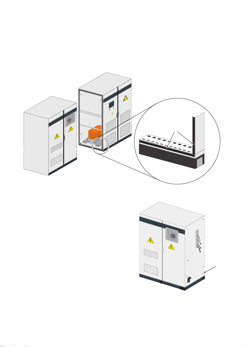
1. Attach the included sealing material all around the cabinet frame (A) of the AC cabinet.
A
2. Position the switch cabinet units (DC/inverter cabinet and AC cabinet) near the installation site.
3. During mounting, insert the PE cable through the
cable gland (A).
4. Mount the switch cabinet units (DC/inverter cabinet
and AC cabinet) at the installation site as described
in the installation guide.
5. Connect the PE cable as described in the installation
guide.
☑ The switch cabinet units are mounted and can now
be screwed together.
Installation Guide 2/5 SC_Chem_Aktiv-IEN092911
A
Page 3

SMA Solar Technology AG Mounting and internal cabling
3.2 Screwing the switch cabinet units together
1. Open the AC cabinet.
2. Connect the switch cabinet units at positions A and B with the provided M8 x 45 mm screws,
washers and locking washer. Torque: 21 Nm.
The switch cabinet units are screwed together in the AC cabinet.
☑ The switch cabinet units are connected to each other. Continue with connecting the power
cables.
DC/inverter cabinet side view AC cabinet side view
A
Installation Guide 3/5 SC_Chem_Aktiv-IEN092911
B
Page 4

SMA Solar Technology AG Mounting and internal cabling
3.3 Connecting the power cables
Th e po wer cabl es a re i ncl ude d in the d eli ver y an d mus t be con nected to the power units in the inverter
cabinet and to the sine filter choke in the AC cabinet. 3 cables are connected per phase. The cable
ro uti ng i n th e right a nd l eft sys tem is di ffe ren t. The fo llo win g ill ust rat ion shows th e po sit ion of t he gland s
in the left system, the position of the glands in the right system are mirror-inverted.
A
B
3.3.1 Connecting the power cables in the left system
1. Connect L3 at the lower power unit in the inverter cabinet.
2. Insert L3 through the cable gland A.
3. Connect L3 at the sine filter in the AC cabinet according to the label.
4. Tighten the cable gland A.
5. Connect L1 at the middle power unit in the inverter cabinet.
6. Insert L1 through the cable gland B.
7. Connect L1 at the sine filter in the AC cabinet according to the label.
8. Tighten the cable gland B.
9. Connect L2 at the upper power unit in the inverter cabinet.
10. Insert L2 through the cable gland C.
11. Connect L2 at the sine filter in the AC cabinet according to the label.
12. Tighten the cable gland C.
Installation Guide 4/5 SC_Chem_Aktiv-IEN092911
Page 5

SMA Solar Technology AG Mounting and internal cabling
3.3.2 Connecting the power cables in the right system
1. Connect L1 at the lower power unit in the inverter cabinet.
2. Insert L1 through the cable gland A.
3. Connect L1 at the sine filter in the AC cabinet according to the label.
4. Tighten the cable gland A.
5. Connect L3 at the middle power unit in the inverter cabinet.
6. Insert L3 through the cable gland B.
7. Connect L3 at the sine filter in the AC cabinet according to the label
8. Tighten the cable gland B.
9. Connect L2 at the upper power unit in the inverter cabinet.
10. Insert L2 through the cable gland C.
11. Connect L2 at the sine filter in the AC cabinet according to the label.
12. Tighten the cable gland C.
Laying cables
The power cables must be bundled in the inverter cabinet by using cable ties. This prevents
the cables from being damaged by pointed or sharp metal edges.
☑ The power cables are connected.
3.4 Connecting the control cables to the transfer terminal strip in the AC cabinet
The control cables (A) are routed to the outside of the
DC/inverter cabinet during factory production.
1. Insert the control cables into the jacks in the AC
cabinet as described in the Sunny Central Installation
Guide.
• Make sure the plugs are not swapped.
☑ The control cables are connected.
Installation Guide 5/5 SC_Chem_Aktiv-IEN092911
A
 Loading...