

Page 1
CA
US
Central Inverter
SUNNY CENTRAL 500HE-US/500HE-CA
Operating Manual
SC500HEUS-eng-BE-BUS120320 | 98-4104420 | Version 2.0
Page 2

Page 3

SMA America, LLC Legal Restrictions
Copyright © 2012 SMA America,LLC. All rights reserved.
No part of this document may be reproduced, stored in a retrieval system, or transmitted, in any form
or by any means, electronic, mechanical, photographic, magnetic or otherwise, without the prior
written permission of SMA America,LLC.
Neither SMA America,LLC nor SMA Solar Technology Canada Inc. makes representations, express
or implied, with respect to this documentation or any of the equipment and/or software it may
describe, including (with no limitation) any implied warranties of utility, merchantability, or fitness for
any particular purpose. All such warranties are expressly disclaimed. Neither SMA America,LLC nor
its distributors or dealers nor SMA Solar Technology Canada Inc. nor its distributors or dealers shall
be liable for any indirect, incidental, or consequential damages under any circumstances.
(The exclusion of implied warranties may not apply in all cases under some statutes, and thus the
above exclusion may not apply.)
Specifications are subject to change without notice. Every attempt has been made to make this
document complete, accurate and up-to-date. Readers are cautioned, however, that
SMAAmerica,LLC and SMA Solar Technology Canada Inc. reserve the right to make changes
without notice and shall not be responsible for any damages, including indirect, incidental or
consequential damages, caused by reliance on the material presented, including, but not limited to,
omissions, typographical errors, arithmetical errors or listing errors in the content material.
All trademarks are recognized even if these are not marked separately. Missing designations do not
mean that a product or brand is not a registered trademark.
The Bluetooth
®
word mark and logos are registered trademarks owned by Bluetooth SIG, Inc. and
any use of such marks by SMA America,LLC and SMA Solar Technology Canada Inc. is under
license.
SMA America, LLC
3801 N. Havana Street
Denver, CO 80239 U.S.A.
SMA Solar Technology Canada Inc.
2425 Matheson Blvd. E
8th Floor
Mississauga, ON L4W 5K5
Canada
Operating Manual SC500HEUS-eng-BE-BUS120320 3
Page 4
Important Safety Instructions SMA America, LLC
%"/(&3
8"3/*/(
$"65*0/
/05*$&
IMPORTANT SAFETY INSTRUCTIONS
SAVE THESE INSTRUCTIONS
This manual contains important instructions for the following products:
• Sunny Central 500HE-US
• Sunny Central 500HE-CA
This manual must be followed during installation and maintenance.
The product is designed and tested according to international safety requirements, but as with all
electrical and electronic equipment, certain precautions must be observed when installing and/or
operating the product. To reduce the risk of personal injury and to ensure the safe installation and
operation of the product, you must carefully read and follow all instructions, cautions and warnings
in this manual.
Warnings in this document
A warning describes a hazard to equipment or personnel. It calls attention to a procedure or practice,
which, if not correctly performed or adhered to, could result in damage to or destruction of part or all
of the SMA equipment and/or other equipment connected to the SMA equipment or personal injury.
Symbol Description
DANGER indicates a hazardous situation which, if not avoided, will result in
death or serious injury.
WARNING indicates a hazardous situation which, if not avoided, could result
in death or serious injury.
CAUTION indicates a hazardous situation which, if not avoided, could result
in minor or moderate injury.
NOTICE is used to address practices not related to personal injury.
4 SC500HEUS-eng-BE-BUS120320 Operating Manual
Page 5
SMA America, LLC Important Safety Instructions
Other Symbols in this document
In addition to the safety and hazard symbols described on the previous pages, the following symbol
is also used in this manual:
Symbole Description
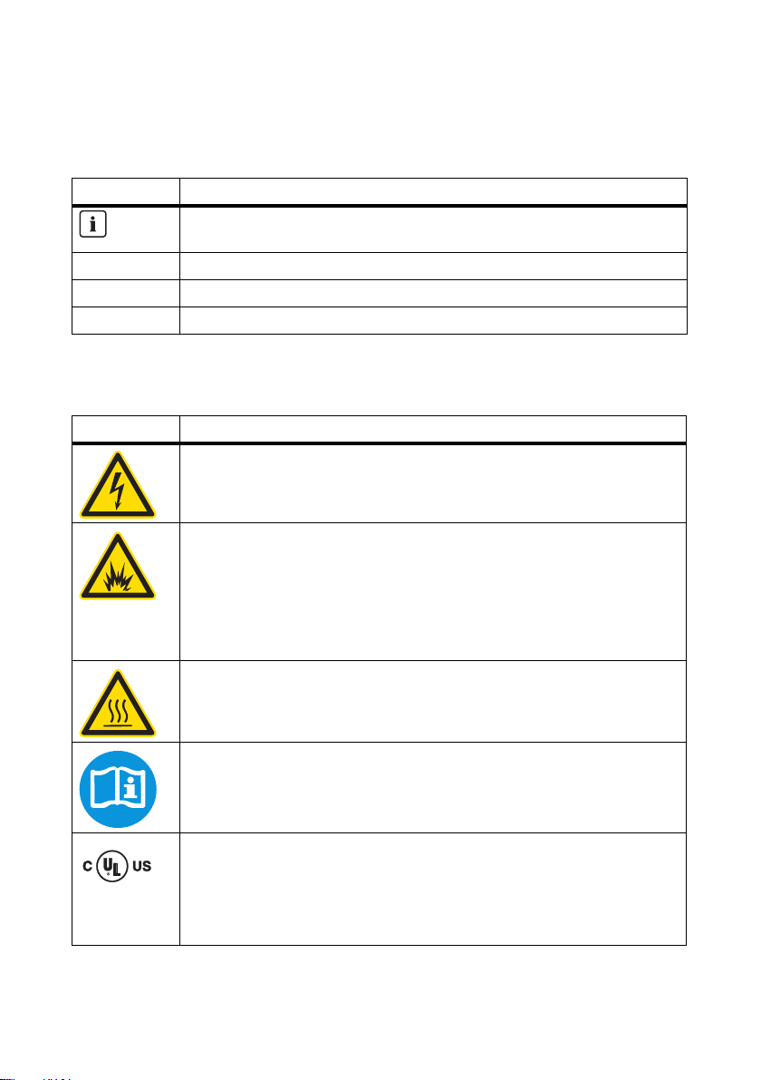
Indicates information that is important for a specific topic or objective, but is not
safety-relevant.
☐ Indicates a requirement for meeting a specific goal.
☑ Desired result
✖ A problem that could occur
Markings on this product
The following symbols are used as product markings with the following meanings.
Symbol Description
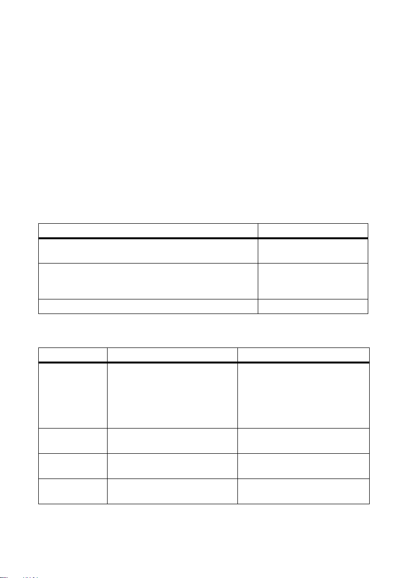
Warning regarding dangerous voltage
The product works with high voltages. All work on the product must only be
performed as described in the documentation of the product.
Electric arc hazards
The product has large electrical potential differences between its conductors. Arc
flashes can occur through air when high-voltage current flows. Do not work on the
product during operation.
If access during operation cannot be avoided, please regard all safety
regulations stated within NFPA 70E.
Beware of hot surface
The product can become hot during operation. Do not touch the product during
operation.
Observe the operating instructions
Read the documentation of the product before working on it. Follow all safety
precautions and instructions as described in the documentation.
Evaluated to the requirements of the Underwriters Laboratories Standard for
Safety for Inverters, Converters, Controllers and Interconnection System
Equipment for Use With Distributed Energy Resources, UL 1741.
The inverter has been additionally evaluated by Underwriters Laboratories to
CAN/CSA C22.2 No. 107.1-1, "General Use Power Supplies".
Operating Manual SC500HEUS-eng-BE-BUS120320 5
Page 6

General Warnings SMA America, LLC
8"3/*/(
General Warnings
General Warnings
All electri cal installations m ust be done in accordance with the local and NationalElectrical Code
ANSI/NFPA 70 or the Canadian Electrical Code® CSAC22.1. This document does not and is not
intended to replace any local, state, provincial, federal or national laws, regulation or codes
applicable to the installation and use of the product, including without limitation applicable
electrical safety codes. All installations must conform with the laws, regulations, codes and
standards applicable in the jurisdiction of installation. SMA assumes no responsibility for the
compliance or noncompliance with such laws or codes in connection with the installation of the
product.
The product contains no user-serviceable parts except for the fans on the bottom of the enclosure
and the filters behind the fans as well as the handle covers on the sides of the unit. For all repair and
maintenance, always return the unit to an authorized SMA Service Center.
Before installing or using the product, read all of the instructions, cautions, and warnings in this
manual.
Before connecting the product to the electrical utility grid, contact the local utility company. This
connection must be made only by qualified personnel.
Wiring of the product must be made by qualified personnel only.
®
6 SC500HEUS-eng-BE-BUS120320 Operating Manual
Page 7

SMA America, LLC Table of Contents
Table of Contents
1 Information on this Manual. . . . . . . . . . . . . . . . . . . . . . . . 11
2 Safety . . . . . . . . . . . . . . . . . . . . . . . . . . . . . . . . . . . . . . . . . 13
2.1 Intended Use. . . . . . . . . . . . . . . . . . . . . . . . . . . . . . . . . . . . . . . 13
2.2 Qualification of Skilled Workers. . . . . . . . . . . . . . . . . . . . . . . . 13
2.3 Safety Precautions. . . . . . . . . . . . . . . . . . . . . . . . . . . . . . . . . . . 14
3 Product Description . . . . . . . . . . . . . . . . . . . . . . . . . . . . . . 17
3.1 Sunny Central . . . . . . . . . . . . . . . . . . . . . . . . . . . . . . . . . . . . . . 17
3.2 Type Label . . . . . . . . . . . . . . . . . . . . . . . . . . . . . . . . . . . . . . . . 20
3.3 Display . . . . . . . . . . . . . . . . . . . . . . . . . . . . . . . . . . . . . . . . . . . 21
3.4 Stop/Start Switch . . . . . . . . . . . . . . . . . . . . . . . . . . . . . . . . . . . 21
3.5 Sunny WebBox. . . . . . . . . . . . . . . . . . . . . . . . . . . . . . . . . . . . . 22
3.6 Sunny Central String-Monitor Controller. . . . . . . . . . . . . . . . . . 23
3.7 Insulation Monitoring Via GFDI . . . . . . . . . . . . . . . . . . . . . . . . 24
3.8 Grid Management . . . . . . . . . . . . . . . . . . . . . . . . . . . . . . . . . . 24
3.8.1 Requirements. . . . . . . . . . . . . . . . . . . . . . . . . . . . . . . . . . . . . . . . . . . . . . . . . 24
3.8.2 Active Power Limitation . . . . . . . . . . . . . . . . . . . . . . . . . . . . . . . . . . . . . . . . . 25
3.8.3 Reactive Power Regulation . . . . . . . . . . . . . . . . . . . . . . . . . . . . . . . . . . . . . . 25
3.9 Active Island Detection . . . . . . . . . . . . . . . . . . . . . . . . . . . . . . . 26
4 Operating the Display . . . . . . . . . . . . . . . . . . . . . . . . . . . . 27
4.1 Display Symbols . . . . . . . . . . . . . . . . . . . . . . . . . . . . . . . . . . . . 27
4.2 Switching Diagram Modes . . . . . . . . . . . . . . . . . . . . . . . . . . . . 29
4.3 Navigating the Menu . . . . . . . . . . . . . . . . . . . . . . . . . . . . . . . . 29
4.4 Menu Structure . . . . . . . . . . . . . . . . . . . . . . . . . . . . . . . . . . . . . 30
4.5 Changing the Time Setting . . . . . . . . . . . . . . . . . . . . . . . . . . . . 31
4.6 Changing the Date Setting . . . . . . . . . . . . . . . . . . . . . . . . . . . . 31
4.7 Displaying the Firmware Version . . . . . . . . . . . . . . . . . . . . . . . 31
Operating Manual SC500HEUS-eng-BE-BUS120320 7
Page 8

Table of Contents SMA America, LLC
5 Configuring the Network Settings . . . . . . . . . . . . . . . . . . 32
6 Communication with the Sunny WebBox . . . . . . . . . . . . 34
6.1 Displaying the Instantaneous Values. . . . . . . . . . . . . . . . . . . . . 34
6.2 Changing Parameters . . . . . . . . . . . . . . . . . . . . . . . . . . . . . . . . 34
7 Active Power Limitation . . . . . . . . . . . . . . . . . . . . . . . . . . . 35
7.1 Power Frequency-Dependent Active Power Limitation . . . . . . . 35
7.2 Power Frequency-Independent Active Power Limitation . . . . . . 36
7.2.1 Selecting the Procedure using the Parameter "P-WMod" . . . . . . . . . . . . . . . 36
7.2.2 "Off" Procedure. . . . . . . . . . . . . . . . . . . . . . . . . . . . . . . . . . . . . . . . . . . . . . . 37
7.2.3 "WCtlCom" Procedure . . . . . . . . . . . . . . . . . . . . . . . . . . . . . . . . . . . . . . . . . 37
7.2.4 "WCnst" Procedure . . . . . . . . . . . . . . . . . . . . . . . . . . . . . . . . . . . . . . . . . . . . 37
7.2.5 "WCnstNom" Procedure . . . . . . . . . . . . . . . . . . . . . . . . . . . . . . . . . . . . . . . . 38
7.2.6 "WCnstNomAnIn" Procedure . . . . . . . . . . . . . . . . . . . . . . . . . . . . . . . . . . . . 38
7.3 Displaying the Active Power Limitation Status . . . . . . . . . . . . . . 38
7.4 Displaying Error Messages and Warnings for Active Power
Limitation. . . . . . . . . . . . . . . . . . . . . . . . . . . . . . . . . . . . . . . . . . 39
8 Reactive Power Regulation . . . . . . . . . . . . . . . . . . . . . . . . 40
8.1 Procedure for Reactive Power Regulation. . . . . . . . . . . . . . . . . 40
8.1.1 Selecting the Procedure using the Parameter "Q-VArMod". . . . . . . . . . . . . . 40
8.1.2 "Off" Procedure. . . . . . . . . . . . . . . . . . . . . . . . . . . . . . . . . . . . . . . . . . . . . . . 41
8.1.3 "VArCtlCom" Procedure . . . . . . . . . . . . . . . . . . . . . . . . . . . . . . . . . . . . . . . . 41
8.1.4 "PFCtlCom" Procedure. . . . . . . . . . . . . . . . . . . . . . . . . . . . . . . . . . . . . . . . . . 41
8.1.5 "VArCnst" Procedure . . . . . . . . . . . . . . . . . . . . . . . . . . . . . . . . . . . . . . . . . . . 42
8.1.6 "VArCnstNom" Procedure . . . . . . . . . . . . . . . . . . . . . . . . . . . . . . . . . . . . . . . 42
8.1.7 "VArCnstNomAnIn" Procedure . . . . . . . . . . . . . . . . . . . . . . . . . . . . . . . . . . . 42
8.1.8 "PFCnst" Procedure . . . . . . . . . . . . . . . . . . . . . . . . . . . . . . . . . . . . . . . . . . . . 43
8.1.9 "PFCnstAnIn" Procedure . . . . . . . . . . . . . . . . . . . . . . . . . . . . . . . . . . . . . . . . 44
8.1.10 "PFCtlW" Procedure . . . . . . . . . . . . . . . . . . . . . . . . . . . . . . . . . . . . . . . . . . . 45
8.1.11 "VArCtlVol" Procedure. . . . . . . . . . . . . . . . . . . . . . . . . . . . . . . . . . . . . . . . . . 46
8.1.12 "VArCtlVolHystDb" Procedure. . . . . . . . . . . . . . . . . . . . . . . . . . . . . . . . . . . . 47
8 SC500HEUS-eng-BE-BUS120320 Operating Manual
Page 9

SMA America, LLC Table of Contents
8.2 Error Messages and Warnings for the Reactive Power
Setpoint. . . . . . . . . . . . . . . . . . . . . . . . . . . . . . . . . . . . . . . . . . . 50
9 Grid Monitoring . . . . . . . . . . . . . . . . . . . . . . . . . . . . . . . . . 51
9.1 How Grid Monitoring Works . . . . . . . . . . . . . . . . . . . . . . . . . . 51
9.2 Monitoring the Line Voltage . . . . . . . . . . . . . . . . . . . . . . . . . . . 51
9.3 Monitoring the Power Frequency . . . . . . . . . . . . . . . . . . . . . . . 52
9.4 Connecting to Grid After Rectifying a Fault . . . . . . . . . . . . . . . 54
10 Troubleshooting . . . . . . . . . . . . . . . . . . . . . . . . . . . . . . . . . 55
10.1 Reading Off Errors . . . . . . . . . . . . . . . . . . . . . . . . . . . . . . . . . . 55
10.2 Rectifying the Error . . . . . . . . . . . . . . . . . . . . . . . . . . . . . . . . . . 56
10.2.1 Error Types and Waiting Times for Errors . . . . . . . . . . . . . . . . . . . . . . . . . . . 56
10.2.2 Errors 01-13 - Power Distribution Grid Errors . . . . . . . . . . . . . . . . . . . . . . . . 57
10.2.3 Errors 34-38 - PV Array Errors. . . . . . . . . . . . . . . . . . . . . . . . . . . . . . . . . . . . 58
10.2.4 Errors 60-87 - Sunny Central Errors . . . . . . . . . . . . . . . . . . . . . . . . . . . . . . . 59
10.2.5 Communication Errors. . . . . . . . . . . . . . . . . . . . . . . . . . . . . . . . . . . . . . . . . . 60
10.3 Confirming the Error . . . . . . . . . . . . . . . . . . . . . . . . . . . . . . . . . 61
11 Instantaneous Values . . . . . . . . . . . . . . . . . . . . . . . . . . . . 62
11.1 Overview of all Instantaneous Values. . . . . . . . . . . . . . . . . . . . 62
11.2 Instantaneous Values by Topic . . . . . . . . . . . . . . . . . . . . . . . . . 63
11.2.1 Instantaneous Values for Active and Reactive Power . . . . . . . . . . . . . . . . . . 63
11.2.2 Error Channels . . . . . . . . . . . . . . . . . . . . . . . . . . . . . . . . . . . . . . . . . . . . . . . 63
11.2.3 Measured Values . . . . . . . . . . . . . . . . . . . . . . . . . . . . . . . . . . . . . . . . . . . . . 63
11.2.4 Device-Internal Values. . . . . . . . . . . . . . . . . . . . . . . . . . . . . . . . . . . . . . . . . . 64
11.2.5 Internal Counters. . . . . . . . . . . . . . . . . . . . . . . . . . . . . . . . . . . . . . . . . . . . . . 64
Operating Manual SC500HEUS-eng-BE-BUS120320 9
Page 10

Table of Contents SMA America, LLC
12 Parameters . . . . . . . . . . . . . . . . . . . . . . . . . . . . . . . . . . . . . 65
12.1 Overview of all Parameters. . . . . . . . . . . . . . . . . . . . . . . . . . . . 65
12.2 Parameters by Topic . . . . . . . . . . . . . . . . . . . . . . . . . . . . . . . . . 75
12.2.1 Parameters for Active Power Limitation . . . . . . . . . . . . . . . . . . . . . . . . . . . . . 75
12.2.2 Parameters for Reactive Power Regulation . . . . . . . . . . . . . . . . . . . . . . . . . . 77
12.2.3 Parameters for Grid Monitoring . . . . . . . . . . . . . . . . . . . . . . . . . . . . . . . . . . 81
12.2.4 Parameters for Grid Support . . . . . . . . . . . . . . . . . . . . . . . . . . . . . . . . . . . . . 83
12.2.5 Device-Internal Parameters . . . . . . . . . . . . . . . . . . . . . . . . . . . . . . . . . . . . . . 84
13 Contact . . . . . . . . . . . . . . . . . . . . . . . . . . . . . . . . . . . . . . . . 87
10 SC500HEUS-eng-BE-BUS120320 Operating Manual
Page 11
SMA America, LLC 1 Information on this Manual
1 Information on this Manual
Validity
This manual applies to the following device types:
• SC 500HE-US from firmware version 1.070
• SC 500HE-CA from firmware version 1.070
Target group
This manual is intended for skilled workers. Only skilled workers are allowed to perform the tasks set
forth in this manual (see section 2.2 "Qualification of Skilled Workers", page 13).
Additional information
Additional information is available at www.SMA-America.com:
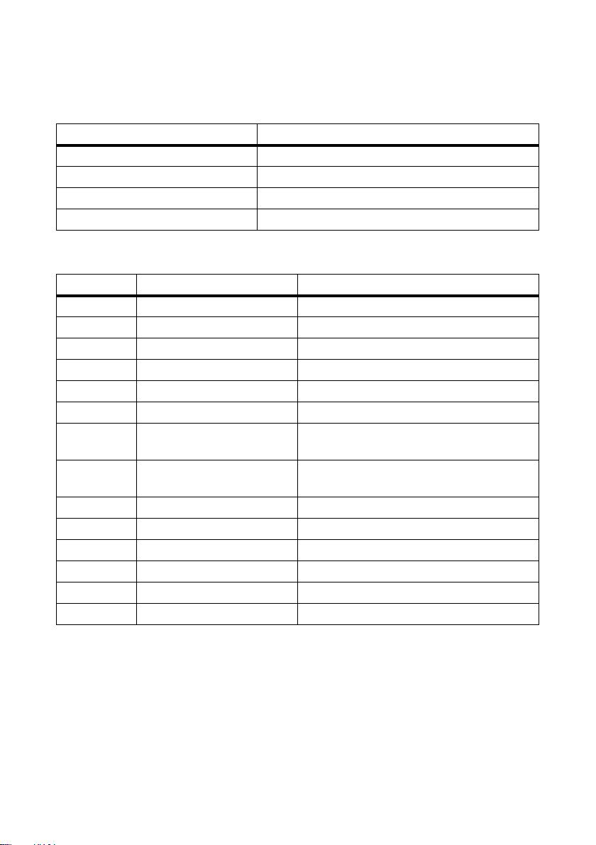
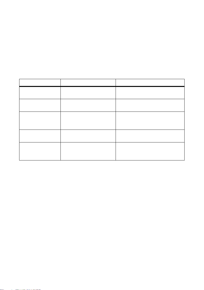
Document title Document type
Installation requirements for SUNNY CENTRAL 500HE-US/
SUNNY CENTRAL 500HE-CA
Transformer Requirements - requirements of medium-voltage and
auxiliary transformers for SUNNY CENTRAL 500HE-US /
SUNNY CENTRAL 500HE-CA
Plant Communication in large-scale PV Plants Technical information
Technical information
Technical information
Typography
Typography Usage Example:
"light" • Display messages
• Parameters
• Instantaneous Values
• Elements of a graphic user
interface
bold • Elements to be entered • Enter 192.168.0.100 in the
> • Several elements that are to be
selected
[Button/key] • Button or key to be selected or
pressed
Operating Manual SC500HEUS-eng-BE-BUS120320 11
• The parameter "P-W" defines the
active power to be fed in.
"IP address" field.
•Select Plant > Devices.
•Select [OK].
Page 12
1 Information on this Manual SMA America, LLC
Nomenclature
The following nomenclature is used in this manual:
Complete designation Designation in this manual
SMA America, LLC SMA
SMA Solar Technology Canada Inc. SMA
Sunny Central 500HE-US Sunny Central or inverter
Sunny Central 500HE-CA Sunny Central or inverter
Abbreviations
Abbreviation Designation Explanation
AC Alternating Current ‒
OCU Operational Control Unit ‒
OCS Operational Control System ‒
DC Direct Current ‒
DSP Digital Signal Processor ‒
ESD Electrostatic Discharge ‒
GFDI Ground-Fault Detection
Interruption
GSM Global System for Mobile
Communication
IP Internet Protocol ‒
LAN Local Area Network ‒
LCD Liquid Crystal Display ‒
MPP Maximum Power Point ‒
PE Protective Earth ‒
PV Photovoltaic ‒
‒
‒
12 SC500HEUS-eng-BE-BUS120320 Operating Manual
Page 13

SMA America, LLC 2 Safety
2Safety
2.1 Intended Use
The Sunny Central is a central inverter that converts direct current generated by the PV modules into
alternating current when the DC input voltage is in the 330 V to 600 V range, and when the
permissible ambient conditions are adhered to. The alternating current that is generated is fed into the
power distribution grid by a transformer that is connected in series.
The inverter may be used both indoors and outdoors. The inverter may only be operated with a
suitable transformer, taking into consideration the maximum permissible DC input voltage and the
permissible ambient temperatures (see Technical information "Transformer Requirements requirements of medium-voltage and auxiliary transformers for SUNNY CENTRAL 500HE-US /
SUNNY CENTRAL 500HE-CA" and the installation manual of the inverter). The transformer must be
designed for the voltages that arise during pulsed mode of the inverter.
The inverter corresponds to the protection class NEMA 3R and can also be operated in rain, sleet,
and snow.
Only persons meeting all of the skills standards for the target group may work on or with the
Sunny Central.
For intended use, please also read the product documentation and observe all safety precautions.
All work on the Sunny Central must be performed with the appropriate tools.
Suitable personal protective equipment according to specifications from NFPA 70E is to be worn by
all persons working on or with the Sunny Central.
Unauthorized persons may not operate the Sunny Central and must keep at a distance from the
Sunny Central.
For safety reasons, it is forbidden to modify the product or install components that are not explicitly
recommended or distributed by SMA for this product.
The Sunny Central may not be operated with its doors open.
The Sunny Central may not be opened when it is raining or when humidity exceeds 95%.
The Sunny Central may not be operated if there are any technical defects.
Any use of the Sunny Central other than that described in the Intended Use section is not regarded as
intended use. Unauthorized installations and modifications compromise operational safety and void
the operation permission as well as all warranty claims.
2.2 Qualification of Skilled Workers
Qualified skilled workers have been adequately trained and have demonstrated the ability and
knowledge to fit, operate, and perform maintenance on the device.
Qualified skilled workers have been trained in how to deal with the dangers and risks associated with
fitting electrical installations and have all the necessary knowledge for averting danger.
Operating Manual SC500HEUS-eng-BE-BUS120320 13
Page 14

2 Safety SMA America, LLC
%"/(&3
2.3 Safety Precautions
Electrical hazards
Electric shock from live voltage
High voltages are present at the inverter and its components. Some maintenance work must be done
when voltage is present. Failure to adhere to the safety messages may lead to severe or lethal
injuries due to electric shock.
• Wear class 2 personal protective equipment.
• Always perform work in compliance with the regulations specified in 29 CFR, Chapter XVII,
Part 1910 (OSHA), NEC, and NFPA 70E.
• Do not touch any live components of the inverter or the medium-voltage grid.
• Follow instructions precisely.
• Observe safety messages.
• Before performing any work on the inverter, always disconnect the inverter if voltage is not
absolutely necessary.
• After disconnecting the inverter, wait at least 10 minutes until the inverter's capacitors have
discharged completely.
• Before performing work on the inverter, ensure that no voltage is present.
Electric shock caused by ground fault
In a ground fault, plant sections that are supposedly grounded may in fact be live. Failure to adhere
to the safety messages may lead to severe or lethal injuries due to electric shock.
• Ensure that no voltage is present before touching any components.
• Wear class 2 personal protective equipment.
Electric shock due to damaged inverter
Operating a damaged inverter can lead to hazardous situations that may result in serious or lethal
injuries caused by electric shock.
• Only operate the inverter if it is in safe and technically faultless working order.
• Only operate the inverter if there is no visible damage.
• Regularly check for visible damage.
• Make sure that all external safety equipment is freely accessible at all times.
• Make sure that all safety equipment is in good working order.
14 SC500HEUS-eng-BE-BUS120320 Operating Manual
Page 15

SMA America, LLC 2 Safety
/05*$&
8"3/*/(
/05*$&
8"3/*/(
Damage to electronic components due to electrostatic discharge
Electrostatic discharge can damage or destroy electronic components.
• Observe the ESD safety regulations when working on the unit.
• Wear personal protective equipment.
• Neutralize any electrostatic charge before touching electronic components, for example by
touching the PE connection of the doors.
Environmental hazards
Danger to life due to blocked escape routes
In hazardous situations, blocked escape routes can lead to serious injury or death.
• An escape route of at least 3 ft. (915 mm) wide must be available at all times.
• Do not place any objects in the escape route area.
• Remove all tripping hazards from the escape routes.
Damage to the inverter caused by dust or moisture penetration
Dust intrusion or moisture penetration can damage the inverter and impair the functionality of the
inverter.
• Do not open the inverter when it is raining or when humidity exceeds 95%.
• Perform maintenance on the Sunny Central only when the environment is dry and free of dust.
Hazards due to human error
Danger to life due to electric shock when the inverter is unlocked
Unlocked inverters can be opened by unauthorized persons. This means that unauthorized persons
have access to components on which lethal voltages are present.
• Ensure that unauthorized persons have no access to the inverter.
• Always lock the inverter.
Operating Manual SC500HEUS-eng-BE-BUS120320 15
Page 16
2 Safety SMA America, LLC
8"3/*/(
$"65*0/
Mechanical hazards
Risk of fire due to failure to observe torque specifications
Failure to follow the torque specifications indicated in the installation manual reduces the ampacity
of the screw connections. This can cause components to overheat and catch fire.
• Always use the torques specified in the installation manual.
• Regularly check that mounted components have always been set at the torque specified in the
installation manual.
Danger from illegible or missing warning signs
Warning signs on the Sunny Central warn operators about hazardous areas and must always be
present and legible.
• Regularly check and make sure that all warning signs are present and undamaged.
• Immediately replace missing, faded, or damaged warning signs.
Thermal hazards
Risk of burns due to hot components.
The components of the Sunny Central can become very hot. Touching these components can lead
to burn injuries.
• Do not touch hot components.
• Wait until hot components have sufficiently cooled down.
• Observe safety messages in the inverter.
• Wear class 2 personal protective equipment.
16 SC500HEUS-eng-BE-BUS120320 Operating Manual
Page 17
SMA America, LLC 3 Product Description
3 Product Description
3.1 Sunny Central
The Sunny Central is a PV inverter that converts the direct current from the PV array into alternating
current for the power distribution grid.
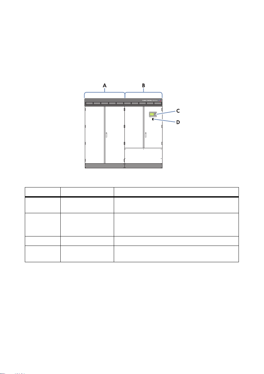
Figure 1: Sunny Central 500HE-US
Position Designation Explanation
A Inverter Cabinet The inverter cabinet contains the inverter bridge for
converting direct current to alternating current.
B Interface Cabinet All AC, DC, and data cables can be connected to the
interface cabinet. This cabinet contains the system control
and optional communication devices.
C Display Read the yield values and error messages off the display.
D Stop/Start Switch Use the stop/start switch to switch the Sunny Central on
or off.
The Sunny Central can be controlled via the Power Reducer Box and the Sunny WebBox, and
therefore can meet the requirements of the grid operator.
Operating Manual SC500HEUS-eng-BE-BUS120320 17
Page 18
3 Product Description SMA America, LLC
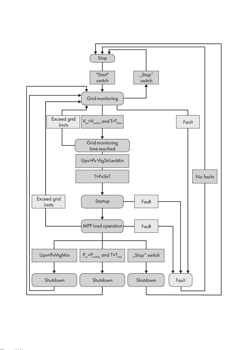
The inverter cycles through various states during operation:
Figure 2: Principle overview of the operating states of the Sunny Central
18 SC500HEUS-eng-BE-BUS120320 Operating Manual
Page 19

SMA America, LLC 3 Product Description
Stop
The Sunny Central is switched off. If the stop/start switch is set to "Start", the Sunny Central switches
to the operating state "Grid monitoring".
Grid Monitoring
The Sunny Central is in the operating state "Grid monitoring". The grid limits will now be monitored
continuously. If the grid limits are exceeded during the monitoring time, the Sunny Central will restart
"Grid monitoring".
If a grid fault does not occur during the grid monitoring time, the AC contactor closes and the
Sunny Central switches to the operating state "Grid monitoring time reached".
Grid monitoring time reached
The Sunny Central is in the operating state "Grid monitoring time reached". If the input voltage V
PV
exceeds the value of the parameter "PvVtgStrLevMin", the Sunny Central waits until the time specified
in the "PvStrT" parameter elapses. If the input voltage VPV does not fall below the value of the
parameter "PvVtgStrLevMin" during this time, the Sunny Central checks whether the power distribution
grid is connected. If a valid power distribution grid is available, the Sunny Central switches to the
operating state "Startup".
The value of the parameter "PvVtgStrLevMin" must be adjusted to conform to the PV array connected
to the Sunny Central.
Startup
The Sunny Central is in the operating state "Startup". The Sunny Central moves to its initial operating
point and begins the feed-in process.
MPP load operation
In the MPP range, the Sunny Central feeds into the power distribution grid and permanently works at
the maximum power point (MPP). If the measured power during the time int erva l "PvPwrMinT" is below
the value of the parameter "PvPwrMin" or the stop/start switch is set to "Stop", the Sunny Central
switches to the operating state "Shutdown".
Shutdown
The Sunny Central is in the operating state "Shutdown". If the stop/start switch is set to "Stop", the
Sunny Central switches to the operating state "Stop". The AC contactor and the DC contactor open
automatically.
If the Sunny Central shuts down because the feed-in conditions have not been met, the Sunny Central
switches to the operating state "Grid monitoring".
Fault
If a fault occurs during operation, the Sunny Central switches off and the fault is shown on the display
(see section 10 "Troubleshooting", page 55).
Operating Manual SC500HEUS-eng-BE-BUS120320 19
Page 20
3 Product Description SMA America, LLC
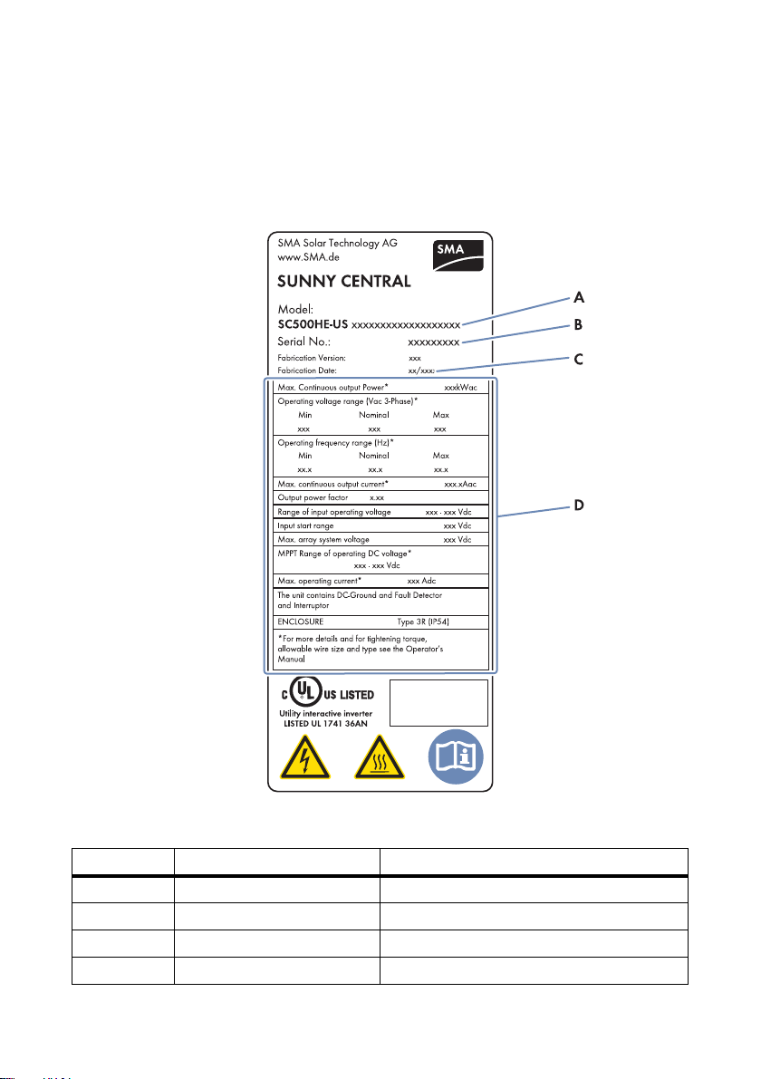
3.2 Type Label
The type label provides a clear identification of the Sunny Central. Two type labels are attached to
the Sunny Central. The type labels can be found on both the top left side in the connection cabinet
and on the right side in the inverter cabinet.
Additionally, the serial number can be found on the roof of the inverter at the top left.
Figure 3: Layout of the type label
Position Designation Explanation
AModel Device type
B Serial no. Inverter serial number
C Fabrication date Date of manufacture
D ‒ Device-specific characteristics
20 SC500HEUS-eng-BE-BUS120320 Operating Manual
Page 21
SMA America, LLC 3 Product Description
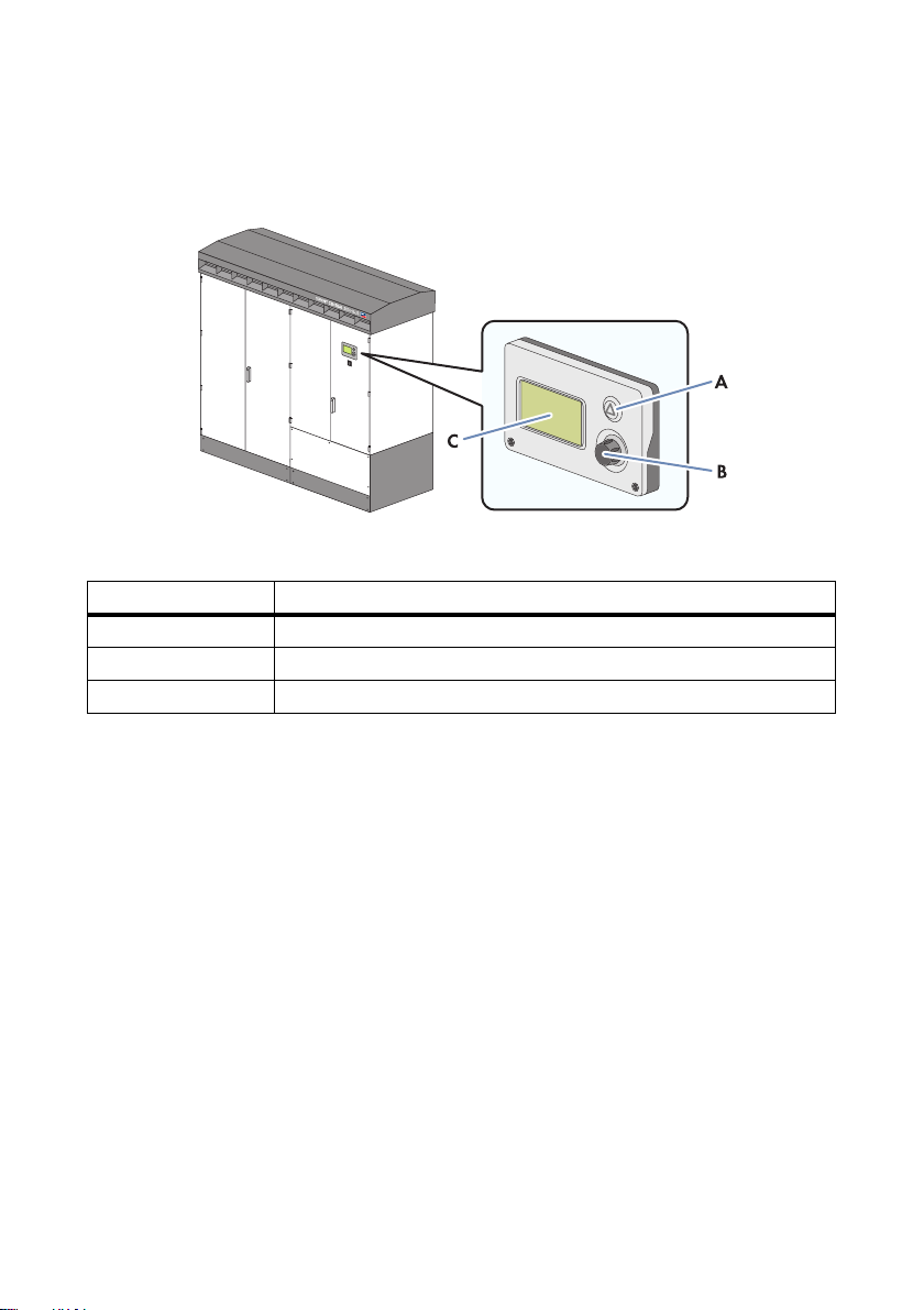
3.3 Display
Read the yield values of the inverter and error messages off the display. If there is an error, the button
glows red.
Figure 4: Display and control elements
Position Designation
AButton
BSwitch
CDisplay
The display can be operated by pushing and pulling the switch and by using the button
(see section 4 "Operating the Display", page 27). By pushing the switch, you can switch on the
backlight of the display.
3.4 Stop/Start Switch
Use the stop/start switch to switch the Sunny Central on or off.
Switch position "Start"
After turning the stop/start switch to "Start", a motor drive closes the DC contactor and the
Sunny Central goes from the operating state "Stop" to the operating state "Grid monitoring". If there
is sufficient irradiation and a valid power distribution grid connection, the Sunny Central switches to
feed-in operation. If there is insufficient irradiation and, in turn, the input voltage is too low, the
Sunny Central remains in the operating state "Grid monitoring".
Operating Manual SC500HEUS-eng-BE-BUS120320 21
Page 22
3 Product Description SMA America, LLC
Switch position "Stop"
If the stop/start switch is turned to "Stop" while the Sunny Central is in the operating state
"Grid monitoring", a motor drive opens the DC contactor. The Sunny Central switches to the operating
state "Stop".
If the stop/start switch is turned to "Stop" while the Sunny Central is in the operating state
"MPP load operation", the Sunny Central switches to the operating state "Shutdown". Once shutdown
is complete, the AC contactor and the DC contactor open automatically and the Sunny Central
switches to the operating state "Stop".
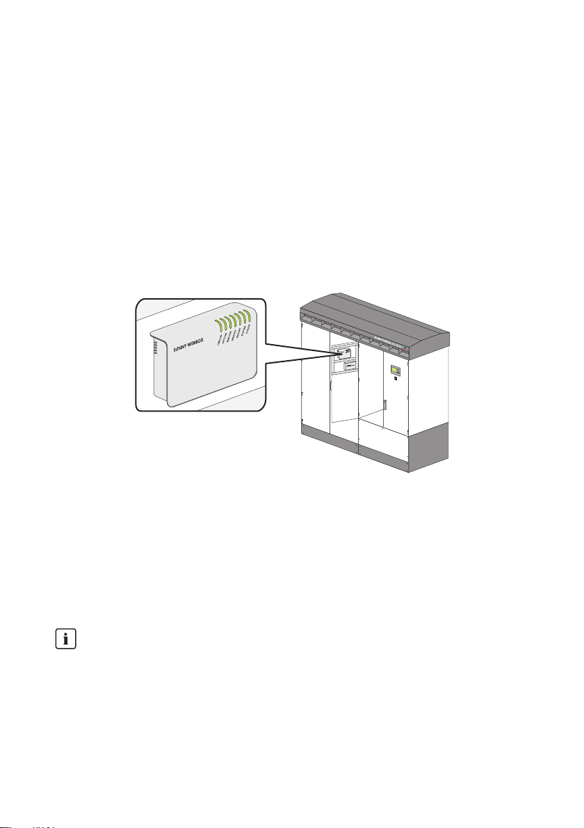
3.5 Sunny WebBox
The Sunny WebBox is a device that monitors and controls the inverter. The Sunny WebBox
establishes the connection between the PV plant and its operator.
Figure 5: Sunny WebBox in the Sunny Central
The Sunny WebBox collects all the data from connected devices. Using the Sunny WebBox, the
monitoring, parameterization, and remote diagnosis of the Sunny Central can be performed via a
computer. The operator can access all data stored in the Sunny WebBox via an Internet connection
or a GSM modem.
You can configure the settings of the Sunny WebBox in the web browser by entering the IP address
of the Sunny WebBox.
Communication type of the PV plant
The interface of the Sunny WebBox is set by default to "SMA-COM" and a 19 200 baud rate.
Do not modify these settings.
22 SC500HEUS-eng-BE-BUS120320 Operating Manual
Page 23
SMA America, LLC 3 Product Description
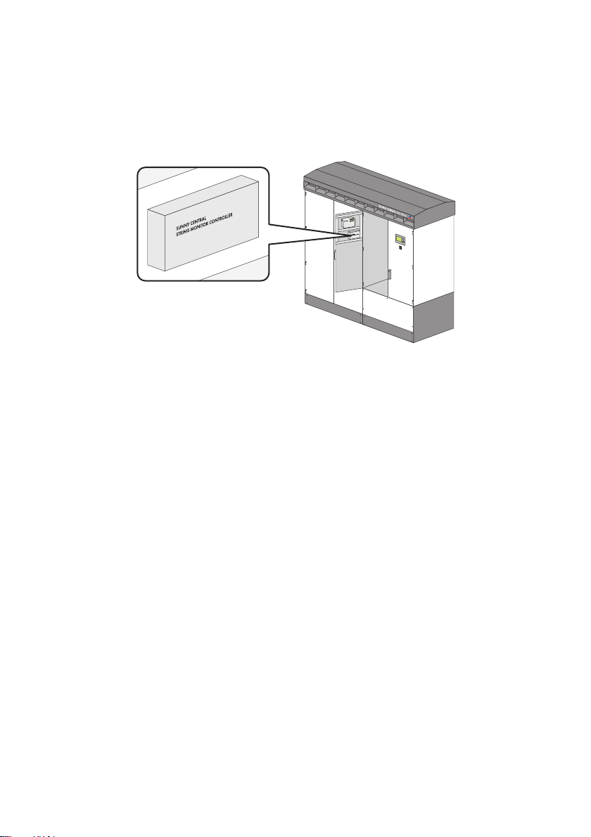
3.6 Sunny Central String-Monitor Controller
Depending on which options are ordered, the Sunny Central may be equipped with a Sunny Central
String-Monitor Controller for stringcurrent monitoring. The Sunny Central String-Monitor Controller
allows communication between the Sunny Central String-Monitors and the Sunny Central.
Figure 6: Sunny Central String-Monitor Controller
The Sunny Central String-Monitors measure the string currents via an integrated measuring circuit
board and continuously calculate the average value of the string currents. The measuring circuit board
compares the string currents with the average values. If a string current exceeds or falls below a
specified tolerance for the average value, a warning or fault is generated and displayed via the
Sunny WebBox user interface.
Operating Manual SC500HEUS-eng-BE-BUS120320 23
Page 24
3 Product Description SMA America, LLC
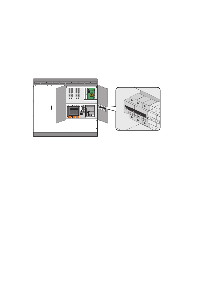
3.7 Insulation Monitoring Via GFDI
The insulation monitoring in the Sunny Central is performed via Ground Fault Detection Interruption
(GFDI).
GFDI is performed via a high-performance k-type miniature circuit-breaker with adjustable operating
current. The miniature circuit-breaker is integrated in the inverter and connected between a positively
or negatively grounded input busbar and the grounding busbar.
Figure 7: GFDI in the Sunny Central
3.8 Grid Management
3.8.1 Requirements
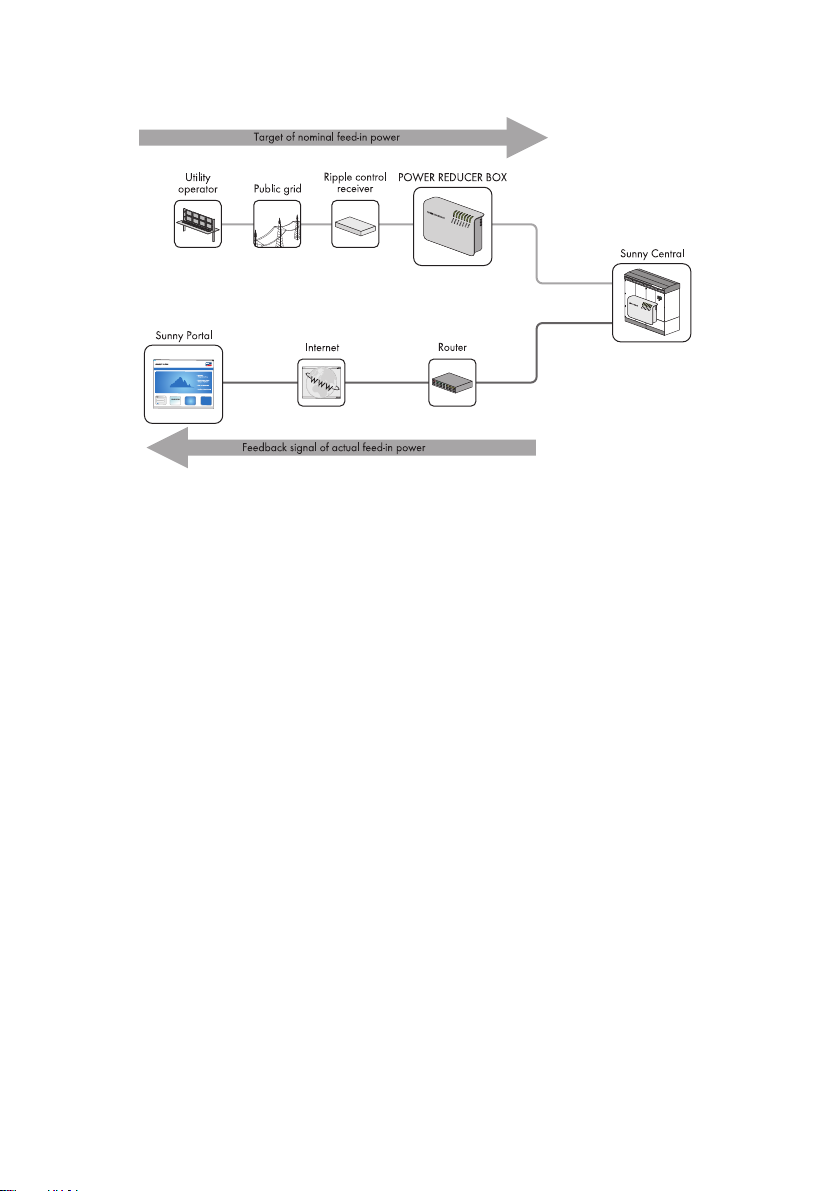
PV plants must participate in feed-in management in accordance with IEEE 1547. Most importantly
the grid operator must be able to limit the power of the PV plant by remote control and temporarily
reduce it to zero in critical cases. The relevant control commands of the grid operator must therefore
be transmitted to the Sunny Central quickly and reliably for implementation.
The following figure shows how the specifications of the grid operator are implemented. The
Power Reducer Box sends the specifications of the grid operator to the inverters.
24 SC500HEUS-eng-BE-BUS120320 Operating Manual
Page 25
SMA America, LLC 3 Product Description
Figure 8: Principle of grid integration
Besides the Power Reducer Box, there are two other options for meeting the requirement of the grid
operator:
• Receiving the signals via two analog inputs on the Sunny Central
• Manual specification adjustment via parameters
3.8.2 Active Power Limitation
There are five methods for limiting the active power independent o f th e po wer fre que ncy . Th e limit ca n
be defined using a parameter and supplied by the grid operator via an external signal.
At the same time, the active power can be limited depending on the power frequency (for information
on active power limitation parameterization, see section 7 "Active Power Limitation", page 35).
3.8.3 Reactive Power Regulation
The Sunny Central can provide reactive power. There are eleven methods for specifying the reactive
power target value. They include entering a fixed parameter, processing an external signal from the
grid operator or specifying the reactive power using characteristic curve parameters (for information
on reactive power regulation, see section 8 "Reactive Power Regulation", page 40).
Operating Manual SC500HEUS-eng-BE-BUS120320 25
Page 26

3 Product Description SMA America, LLC
3.9 Active Island Detection
The Active Island Detection function detects the formation of stand-alone grids during a grid failure
and disconnects the Sunny Central from the power distribution grid.
Loss of UL certification
The Active Island Detection function is standardized by IEEE 1547. Deactivation of the
islanding detection results in the loss of the UL certification of the inverter and SMA is not liable
for any resulting damage.
Stand-alone grids form when the following conditions occur simultaniously:
• The medium-voltage grid fails.
• The Sunny Central feeds in an amount x of power.
• There is a consumer on the same branch of the grid with a load equal to the amount x of power.
26 SC500HEUS-eng-BE-BUS120320 Operating Manual
Page 27
SMA America, LLC 4 Operating the Display
4 Operating the Display
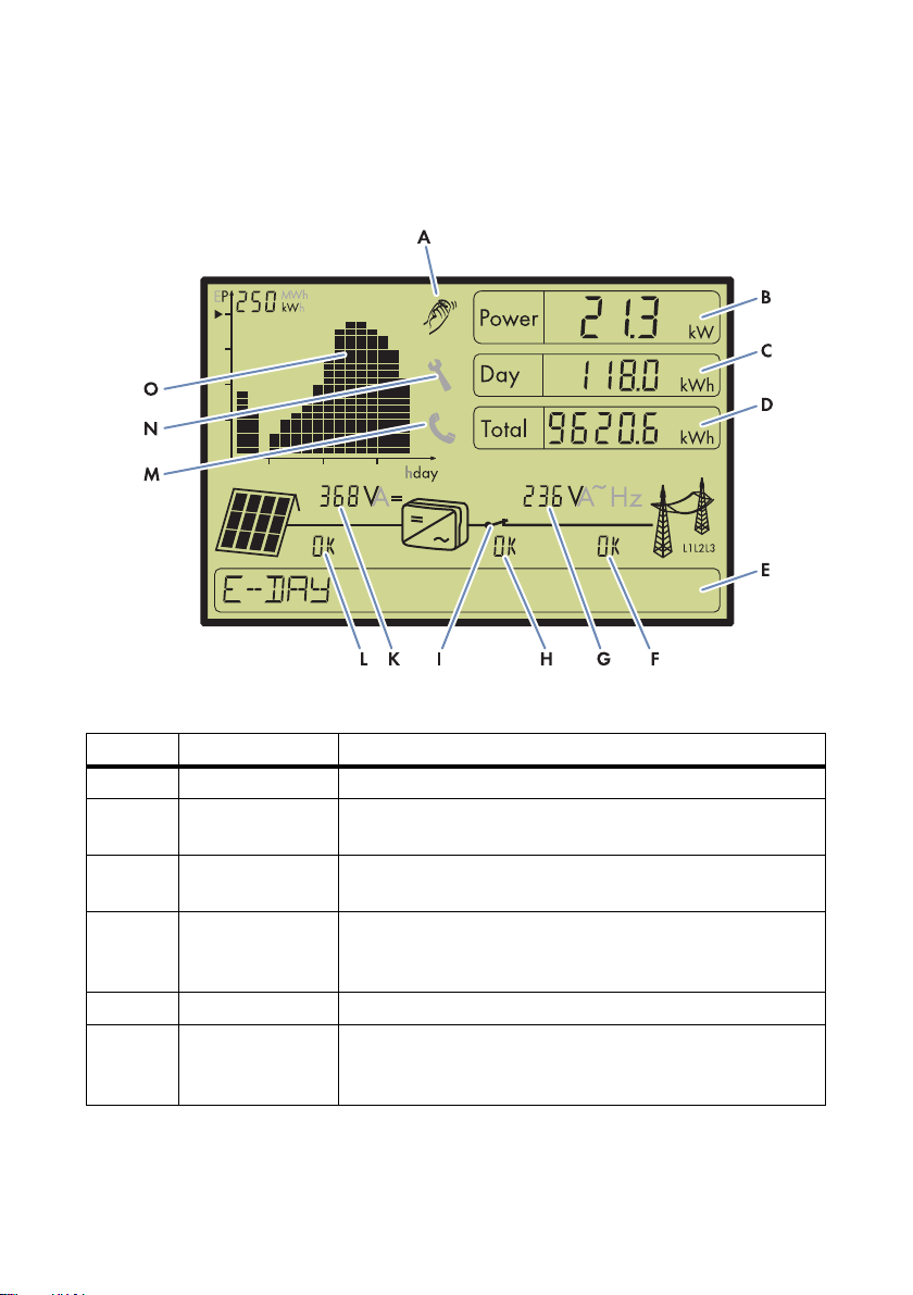
4.1 Display Symbols
Figure 9: Display layout (example)
Position Designation Explanation
A Tapping Tapping on the enclosure switches on the backlight.
B Power Power that the Sunny Central is feeding into the power
distribution grid. The display is updated every 5 seconds.
C Day Energy that the Sunny Central has fed into the grid today.
The display is updated every 5 seconds.
D Total Energy that the Sunny Central has fed into the power distribution
grid during its operating time. The display is updated every
5 seconds.
E Text line The text line shows the menu or an error description.
F Power distribution
grid error number
Operating Manual SC500HEUS-eng-BE-BUS120320 27
If there is an error in the power distribution grid, an error number
will be shown in this position (see section
10 "Troubleshooting", page 55)
Page 28

4 Operating the Display SMA America, LLC
Position Designation Explanation
G Grid values In this position, the display shows the following values of the
power distribution grid:
•Voltage
•Frequency
• Average value of the current for all 3 line conductors
The display switches between the values every 2 seconds.
H Sunny Central error
number
If there is an error in the Sunny Central, an error number will be
shown in this position (see section
10 "Troubleshooting", page 55).
I Grid relay Grid relay open: The Sunny Central is not feeding into the powe r
distribution grid, e.g. at night.
Grid relay closed: The Sunny Central is feeding into the power
distribution grid.
K PV array values In this position, the display shows the following values of the
PV array:
•Voltage
•Current
The display switches between the values every 2 seconds.
L PV array error
number
If there is an error in the PV array, an error number will be shown
in this position (see section 10 "Troubleshooting", page 55).
M Telephone receiver If this symbol is lit, there is an error in the Sunny Central that
cannot be rectified on site. Contact the SMA Service Line
(see section 13 "Contact", page 87)
N Wrench If this symbol is lit, there is an error that can be rectified on site
(see section 10 "Troubleshooting", page 55).
O Diagram The power fed in by the Sunny Central is represented in a
diagram on the display. View the diagram in day mode
"E-HISTORY" or in hour mode "E-DAY" (see section
4.2 "Switching Diagram Modes", page 29). The diagram
updates every 5 seconds.
28 SC500HEUS-eng-BE-BUS120320 Operating Manual
Page 29

SMA America, LLC 4 Operating the Display
4.2 Switching Diagram Modes
View the power fed in by the Sunny Central as a diagram in the display. The diagram can be shown
in day mode or hour mode.
Figure 10: Diagram in hour mode and day mode (examples)
Position Designation
A Diagram in hour mode
B Diagram in day mode
C Energy fed in during the current day
D Power fed in during the current hour
ENo power is fed in
The diagram is shown in day mode by default. The diagram displays a total of 16 hours or 16 days
as bars. The current hour or the current day is the bar furthest to the right in the diagram (C and D).
With every new hour or new day, the diagram scrolls further to the left, out of the screen.
• To change to the day mode diagram view, turn the switch next to the display to the left.
• To change to the hour mode diagram view, turn the switch to the right.
4.3 Navigating the Menu
Using the switch next to the display, you can navigate the menu and select and configure values.
• To access the menu, press and hold the switch and the button for 2 seconds.
• To change the category, turn the switch (see section 4.4 "Menu Structure", page 30).
• To select a category tap the switch once.
• To go back, turn the switch until "BACK" shows on the display, tap the switch.
• To confirm an entry, tap the switch once.
• To increase or reduce values, turn the switch to the right or to the left.
Operating Manual SC500HEUS-eng-BE-BUS120320 29
Page 30

4 Operating the Display SMA America, LLC
4.4 Menu Structure
Access the menu in the text line. The menu has the following menu structure.
Menu level 1 Menu level 2 Menu level 3 Menu level 4
SETTINGS CURRENT TIME
TIME SETTINGS SET CURRENT TIME HOUR
MIN
BACK
SET CURRENT DATE YEAR
MONTH
DAY
BACK
BACK
BACK
INFO VERSION BFR
VERSION DSP
VERSION DISPLAY
VERSION LCD
BACK
BACK
Category Explanation
SETTINGS Set the date and time and read off the current time.
CURRENT TIME This category shows the current time.
TIME SETTINGS Change time and date (see section 4.5 "Changing the Time
Setting", page 31 and section 4.6 "Changing the Date Setting", page 31)
INFO This category shows the firmware version of the display and the
Sunny Central.
VERSION BFR This category shows the firmware version of the Sunny Central operation
control unit.
VERSION DSP This category shows the firmware version of the Sunny Central digital
signal processor.
VERSION DISPLAY This category shows the firmware version of the display.
VERSION LCD This category shows the firmware version of the LCD display.
30 SC500HEUS-eng-BE-BUS120320 Operating Manual
Page 31

SMA America, LLC 4 Operating the Display
4.5 Changing the Time Setting
1. Press the switch and the button for 2 seconds.
☑ The text line reads "SETTINGS".
2. Select TIME SETTINGS > SET CURRENT TIME > HOUR.
3. Use the switch to select the desired hour and confirm by tapping the switch.
4. Select MIN.
5. Use the switch to select the desired minute and confirm by tapping the switch.
4.6 Changing the Date Setting
1. Press the switch and the button for 2 seconds.
☑ The text line reads "SETTINGS".
2. Select TIME SETTINGS > SET CURRENT DATE > YEAR.
3. Use the switch to select the desired year and confirm by tapping the switch.
4. Select MONTH.
5. Use the switch to select the desired month and confirm by tapping the switch.
6. Select DAY.
7. Use the switch to select the desired day and confirm by tapping the switch.
4.7 Displaying the Firmware Version
1. Press the switch and the button for 2 seconds.
☑ The text line reads "SETTINGS".
2. Select INFO.
3. Use the switch to select the desired firmware version (see section 4.4 "Menu Structure", page 30).
4. Tap the switch.
5. Read off the desired firmware version.
Operating Manual SC500HEUS-eng-BE-BUS120320 31
Page 32

5 Configuring the Network Settings SMA America, LLC
5 Configuring the Network Settings
In order to access the inverter via the Internet, the Sunny WebBox must be set up in a plant network
(for information on the Sunny WebBox, see the SunnyWebBox user manual. In order for multiple
Sunny Centrals to operate in the same network, the Sunny WebBox must receive a unique network
address from every Sunny Central (for information on the network concept in a PV plant,
see technical information "Plant Communication in large-scale PV plants" at www.SMA-America.com).
Settings:
• Set the IP address on the computer
• Set the IP address of the Sunny WebBox
Setting the IP address on the computer
1. In Windows, select Start > Run.
2. Enter ncpa.cpl in the box and press [OK].
☑The "Network Connections" window opens.
3. Double-click on the LAN connection via which the Sunny Central is connected.
4. Select [Properties].
☑The "Local Area Connection Properties" window opens.
5. Mark "Internet Protocol (TCP/IP)" and select [Properties].
☑The "Internet Protocol (TCP/IP) Properties" window opens.
6. Note down the existing network settings so that you can restore the settings in your computer
after commissioning the Sunny Central.
7. In the "Internet Protocol (TCP/IP) Properties" window, enter the following properties:
•Enter 192.168.0.100 in the "IP address" field.
•Enter 255.255.255.0 in the "Subnet mask" field.
8. Select [OK].
9. In the "Local Area Connection Properties" window, select [OK].
☑ The computer is set according to the network settings of the Sunny Central.
32 SC500HEUS-eng-BE-BUS120320 Operating Manual
Page 33

SMA America, LLC 5 Configuring the Network Settings
Setting the IP address of the Sunny WebBox
1. Co nne ct a lap top to t he S unn y We bBo x us ing a pa tch cab le. For this purp ose , us e th e cr oss ove r
cable.
2. Enter 192.168.0.168 in the address bar of the web browser.
☑ The user interface of the Sunny WebBox appears.
3. Enter the installer password in the appropriate field on the homepage.
4. Select [Login].
5. Select WebBox > Settings > Network.
6. In the "IP address" field, enter the static IP address under which the Sunny WebBox is to be
accessed in the local network.
7. Enter the subnet mask of your network in the "Subnet mask" field.
8. Enter the gateway IP address of your network in the "Gateway address" field. Usually,
the IP address of the router has to be entered here.
9. Enter the IP address of the DNS server (Domain Name System) in the "DNS server address"
field. Usually, the IP address of the router has to be entered here.
10. Select [Save] and [Confirm].
Operating Manual SC500HEUS-eng-BE-BUS120320 33
Page 34

6 Communication with the Sunny WebBox SMA America, LLC
6 Communication with the Sunny WebBox
6.1 Displaying the Instantaneous Values
1. Start the Sunny WebBox user interface (see the SunnyWebBox user manual).
2. Enter the installer password in the appropriate field on the homepage and confirm with [Login].
3. Select Plant > Devices.
4. Select the desired device from the list.
5. Select the Instantaneous values tab.
☑ The instantaneous values of the desired device are displayed.
6.2 Changing Parameters
1. Start the SunnyWebBox user interface ((see the SunnyWebBox user manual).
2. Enter the installer password in the appropriate field on the homepage and confirm with [Login].
3. Select Plant > Devices.
4. Select the desired device from the list.
5. Select the Parameter tab.
6. Change the value of the respective parameter via the "Value" field.
7. Select [Save].
34 SC500HEUS-eng-BE-BUS120320 Operating Manual
Page 35

SMA America, LLC 7 Active Power Limitation
7 Active Power Limitation
The Sunny Central can limit its active power if requested by the grid operator. The limitation of the
active power can be performed both dependent on the power frequency and independent of the grid
frequency. The frequency-dependent active power limitation is regulated in accordance with the
specifications of IEEE 1547 and cannot be changed. This section describes the function and
parameterization of both types of active power limitation.
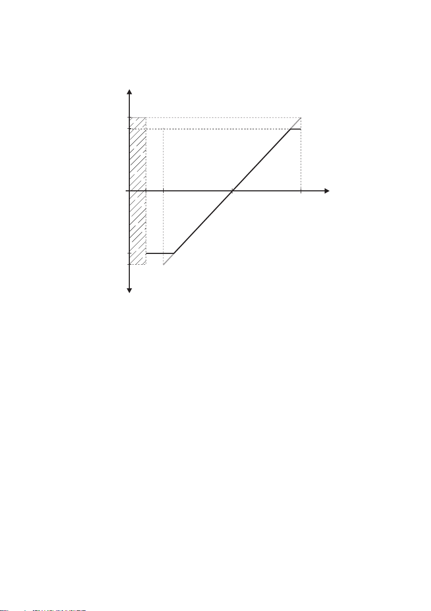
7.1 Power Frequency-Dependent Active Power Limitation
During active power limitation dependent on the power frequency, the Sunny Central constantly
checks the connected power frequency.
Figure 11: Behavior of the Sunny Central when exceeding the "P-HzStr" frequency limit
If the power frequency exceeds a limiting value defined in the parameter "P-HzStr", sho wn u nde r po int
A, the Sunny Central will save the current feed-in capacity P
. The reduced feed-in capacity is
mom
calculated based on this saved value. The reduction of the feed-in capacity is defined by the
parameter "P-WGra". T his parameter ind icates the percentage of the saved power P
by which the
mom
power per Hz will be reduced if the power frequency continues to rise.
If the power frequency decreases again as shown in point B, the last reached feed-in capacity will
remain valid. Only if the power falls below the limiting value defined in the parameter "P-HzStop",
shown here in point C, can the fed-in power be increased again. The saved value P
mom
will be
rendered invalid.
If the power frequency exceeds the grid limit, the Sunny Central will shut down and switch over to the
operating state "Grid monitoring". The Sunny Central will remain in the "Grid monitoring" operating
state until all feed-in conditions are fulfilled again.
Operating Manual SC500HEUS-eng-BE-BUS120320 35
Page 36

7 Active Power Limitation SMA America, LLC
Calculating the active power limit
Formula: P
Grenz
= P
mom
– ( (f
– P-HzStr) * P-WGra * P
Netz
mom
)
P
Grenz
P
mom
Power frequency
f
Netz
Power limit
Current power
P-HzStr Selected frequency limit at which the active power will be reduced
P-WGra Gradient of the active power limitation
Example: Calculating the active power limit
A Sunny Central with 500 kW feeds in 350 kW (P
) into the power distribution grid.
mom
The frequency will reach up to 51.2 Hz.
The difference between the current power frequency and "P-HzStr" (51.2 Hz - 50.2 Hz) multiplied
by the gradient "P-WGra" (40%/Hz) results in an active power reduction of 40% of the last
available power P
(350 kW). This results in an active power limitation of 140 kW and a
mom
maximum active power of 210 kW.
Calculation:
210 kW = 350 kW – ( (51.2 Hz – 50.2 Hz) * 40 %/Hz * 350 kW )
7.2 Power Frequency-Independent Active Power Limitation
7.2.1 Selecting the Procedure using the Parameter "P-WMod"
Use the "P-WMod" parameter to set the procedure for the frequency-independent active power
li mit ati on. Use the par ame ter to c onf igu re h ow t he p ara met ers of the grid operator should be received
and implemented. The default value for this parameter is "WCnst".
There are five different procedures for power frequency-independent active power limitation:
Procedure Description
Off The active power is limited to the nominal device power "Pmax".
WCtlCom The active power limitation is received by the Sunny WebBox via
the Power Reducer Box and then forwarded to the Sunny Central.
WCnst The active power limitation is entered as an absolute value via the
parameter "P-W".
WCnstNom The active power limitation is entered as a percentage value via
the parameter "P-WNom".
WCnstNomAnIn Active power limitation is set at the input terminals using an analog
signal for specifying the target value.
36 SC500HEUS-eng-BE-BUS120320 Operating Manual
Page 37

SMA America, LLC 7 Active Power Limitation
Parameter blocking
The parameter "P-WMod" may only be changed when the device is in the operating state
"Stop". The entry will not be accepted in other operating states.
1. Ensure that the inverter is in the operating state "Stop".
2. Launch the Sunny WebBox user interface.
3. Enter the installer password in the appropriate field on the homepage and confirm with [Login].
4. Change the parameter "P-WMod" in the Sunny WebBox user interface
(see section 6.2 "Changing Parameters", page 34).
5. Change the parameters belonging to the selected procedure.
6. Confirm the parameter entry with [Save].
7.2.2 "Off" Procedure
The feed-in capacity is limited by the parameter "Pmax".
The parameter "Pmax" defines the nominal power of the inverter and is set to the local conditions
during commissioning. Before the parameter "Pmax" can be changed, the device must be in the
operating state "Stop" and the installer password must be entered.
Parameter used Pmax
7.2.3 "WCtlCom" Procedure
The target value for active power limitation is received by the Sunny WebBox via the
Power Reducer Box and then forwarded to the Sunny Central. If the Sunny Central has received no
signal for 5 minutes, the error message "P-WModFailStt" will be displayed (see section
7.4 "Displaying Error Messages and Warnings for Active Power Limitation", page 39).
Parameters used None
7.2.4 "WCnst" Procedure
The active power limitation is entered as an absolute value via the parameter "P-W".
The parameter "P-W" defines the active power to be fed in. The parameter "P-W" can be changed
during feed-in operation. The value of the parameter "P-W" may be as large as the value of the
parameter "Pmax" at maximum.
Parameter used P-W
Operating Manual SC500HEUS-eng-BE-BUS120320 37
Page 38

7 Active Power Limitation SMA America, LLC
7.2.5 "WCnstNom" Procedure
Th e ac tiv e powe r li mit ati on is s et a s a per cen tag e vi a the p ara meter "P-WNom". The percentage value
refers to the parameter "Pmax".
The parameter "P-WNom" indicates the percentage of maximum possible power to be fed in. The
parameter "P-WNom" can be changed during feed-in operation.
Parameter used P-WNom
7.2.6 "WCnstNomAnIn" Procedure
The active power limitation is set at the input terminals using an analog signal for specifying the target
value (see the inverter installation manual). This is usually implemented by a ripple control receiver.
The electrical current strength of the connected signal determines the rated active power.
The analog measured values must be between 4 mA and 19 mA. If the analog signal is less than
2 mA, the error message will be displayed in the instantaneous value "P-WModFailStt"
(see section 7.4 "Displaying Error Messages and Warnings for Active Power Limitation", page 39).
Signal Power limit Description
< 2 mA Last valid value and/or "Pmax"
after restart
2mA…4mA 0 kW No power is fed into the grid.
4 mA … 19 mA 0 kW … Pmax Fed-in energy is determined using a
> 19 mA Pmax Fed-in energy is equal to the value of the
Signal is in the invalid range.
characteristic curve
parameter "Pmax".
The analog value is converted to a target value for active power limitation. Here, the parameter
"Pmax" is the end point of the linear characteristic curve.
Parameters used None
7.3 Displaying the Active Power Limitation Status
The instantaneous value "P-WModStt" displays the status of the active power limitation.
• Display the instantaneous value
(see section 6.1 "Displaying the Instantaneous Values", page 34).
38 SC500HEUS-eng-BE-BUS120320 Operating Manual
"P-WModStt" on the SunnyWebBox user interface
Page 39

SMA America, LLC 7 Active Power Limitation
Display Explanation
"Off" No procedure for active power limitation has been selected..
"WMax" Active power is limited by the specified maximum limit. Here, the limit is based on
the value of the parameter "Pmax".
"Hz" Active power is limited by a frequency increase.
"Tmp" Active power is limited due to temperature derating.
"AmpPv" Active power is limited via PV power limitation.
7.4 Displaying Error Messages and Warnings for Active Power Limitation
The instantaneous value "P-WModFailStt" displays the error messages or warnings associated with
active power limitation.
• Display the instantaneous value
section 6.1 "Displaying the Instantaneous Values", page 34).
Display Cause and corrective measures
"Off" No procedure for active power limitation has been selected.
"Ok" A procedure for active power limitation has been selected and there are no errors.
"ComFail" The procedure "WCtlCom" has been selected and the expected signal with a valid
active power limitation has been absent for 5 minutes.
Corrective measures:
• E nsu re t hat the Sunny W ebB ox a nd t he Pow er R edu cer Box can be a ccessed
via the Internet.
• Ensure that the Sunny WebBox and the Power Reducer Box are connected
correctly.
• Ensure that the cabling between the Sunny WebBox and the inverter is OK.
"AnInFail" The procedure "WCnstNomAnIn" has been selected and the value measured at the
analog input is less than 2 mA.
Corrective measures:
• Ensure that the signal cable is correctly connected to the analog input.
"P-WModFailStt" on the SunnyWebBox user interface (see
Operating Manual SC500HEUS-eng-BE-BUS120320 39
Page 40

8 Reactive Power Regulation SMA America, LLC
8 Reactive Power Regulation
The Sunny Central can supply reactive power if required by the grid operator. The grid operator
defines the procedures and target values used for this.
8.1 Procedure for Reactive Power Regulation
8.1.1 Selecting the Procedure using the Parameter "Q-VArMod"
The parameter "Q-VArMod" is used to select the procedure for reactive power regulation. Use the
parameter to configure how the specifications of the grid operator are to be received and
implemented.
There are eleven different procedures for reactive power regulation. The default value for this
parameter is "Off".
Procedure Description
"Off" The reactive power target value is limited to 0 kVAr.
"VArCtlCom" The reactive power target value is received by the Sunny WebBox via the
Power Reducer Box and forwarded to the Sunny Central. The target value
is transmitted as a percentage and converted to kVAr inside the inverter.
"PFCtlCom" The reactive power target value is received by the Sunny WebBox via the
Power Reducer Box and forwarded to the Sunny Central. A displacement
power factor cos φ is transmitted as a target value.
"VArCnst" The parameter "Q-VAr" is used to set the reactive power target value in
kVAr.
"VArCnstNom" The parameter "Q-VArNom" is used to set the reactive power target value
as a percentage based on "Pmax".
"VArCnstNomAnIn" The reactive power target value is imported through an analog input. The
analog value is converted into a reactive power target value.
"PFCnst" The reactive power target value is set using a displacement power factor
cos φ.
"PFCnstAnIn" The reactive power target value is imported through the analog input for
specifying target values. The analog value is converted into a
displacement power factor cos φ.
"PFCtlW" The displacement power factor cos φ is set depending on the feed-in
capacity. The dependency is depicted by a parameterizable curve.
"VArCtlVol" Reactive power is set depending on the line voltage. The parameterization
of this function depends on the medium voltage.
40 SC500HEUS-eng-BE-BUS120320 Operating Manual
Page 41

SMA America, LLC 8 Reactive Power Regulation
Procedure Description
"VArCtlVolHystDb" The supply of reactive power helps perform voltage-stabilizing measures
in the event of over- or undervoltage. The parameterization is performed
using a reactive power/voltage characteristic curve.
Parameter blocking
The parameter "Q-VArMod" may only be changed when the device is in the operating state
"Stop". The entry will not be accepted in other operating states.
1. Ensure that the inverter is in the operating state "Stop".
2. Start the Sunny WebBox user interface.
3. Enter the password in the appropriate field on the homepage and confirm with [Login].
4. Change the parameter "Q-VArMod" (see section 6.2 "Changing Parameters", page 34).
5. Change the parameters belonging to the selected procedure.
6. Confirm the parameter entry with [Save].
8.1.2 "Off" Procedure
The reactive power target value is limited to 0 kVAr. This target value cannot be influenced.
Parameters used None
8.1.3 "VArCtlCom" Procedure
The reactive power target value is received by the Sunny WebBox via the Power Reducer Box and
forwarded to the Sunny Central. The target value is transmitted as a percentage and converted to
kVAr inside the inverter.
If the Sunny Central has received no signal for 5 minutes, the "Q-VArModFailStt" error message will
be displayed.
Parameters used None
8.1.4 "PFCtlCom" Procedure
The reactive power target value is received by the Sunny WebBox via the Power Reducer Box and
forwarded to the Sunny Central. A displacement power factor cos φ is transmitted as a target value.
If the Sunny Central has received no signal for 5 minutes, the error message will be displayed in the
instantaneous value "Q-VArModFailStt".
Parameters used None
Operating Manual SC500HEUS-eng-BE-BUS120320 41
Page 42

8 Reactive Power Regulation SMA America, LLC
8.1.5 "VArCnst" Procedure
The parameter "Q-VAr" is used to set the reactive power target value in kVAr. For this purpose, the
parameter "Q-VAr" must be in the range of "‒Qmax" to "+Qmax".
Parameter used Q-VAr
8.1.6 "VArCnstNom" Procedure
The parameter "Q-VArNom" is used to set the reactive power target value in percent. The parameter
"Q-VArNom" refers to "Pmax". If the calculated amount of reactive power exceeds the predefined
value "Qmax", the power will be limited to "Qmax". If the calculated amount of reactive power falls
below the predefined value "‒Qmax", the power will be limited to "‒Qmax".
Parameter used Q-VArNom
8.1.7 "VArCnstNomAnIn" Procedure
The reactive power target value is set at the input terminals using an analog signal for specifying the
target value (see the the inverter installation manual). This is usually implemented by a ripple control
receiver.
The analog value is converted into a reactive power target value. The electrical current strength of the
connected signal determines the target value.
The analog measured values must be between 4 mA and 19 mA. If the analog signal is less than
2 mA, the error message will be displayed in the instantaneous value "Q-VArModFailStt".
Signal Power limit Explanation
< 2 mA Last valid value or 0 kVAr after
restart
2mA…4mA −Pmax The maximum amount of negatively
4 mA − Pmax Starting point of the curve
11.5 mA 0 kVAr Zero-crossing of the curve
> 19 mA +Pmax End point of the curve
42 SC500HEUS-eng-BE-BUS120320 Operating Manual
Signal is in the invalid range.
excited reactive power is fed in.
Maximum amount of negatively excited
reactive power is fed in.
No reactive power is fed in.
Maximum amount of positively excited
reactive power is fed in.
Page 43
SMA America, LLC 8 Reactive Power Regulation
11,5
Q [VAr]
1942
- Q
max
- P
max
0
I [mA]
Q
max
P
max
The analog value is converted to a target value for power limitation. Here, the parameter "Pmax" is
the end point of the linear characteristic curve.
Figure 12: Limiting the parameter "Pmax" to the parameter "Qmax"
If the value of "Pmax" exceeds the value of "Qmax", the characteristic curve of the value Q
limited to "Qmax" and the reactive power value in the range from +Q
max
to +P
will constantly
max
max
will be
remain at "Qmax".
If the value of "‒Pmax" falls below the value of "‒Qmax", the characteristic curve of the value ‒Q
will be limited to "‒Qmax" and the reactive power value in the range from ‒Q
max
to ‒P
max
max
will
constantly remain at "‒Qmax".
Parameters used None
8.1.8 "PFCnst" Procedure
The reactive power setpoint is set using the parameters "PF-PF" and "PF-PFExt". The parameter "PF-PF"
indicates the displacement power factor cos φ and the parameter "PF-PFExt" indicates the degree of
overexcitation or underexcitation. The parameter "PFAbsMin" is the start and end point of the linear
characteristic curve.
Parameters used PF-PF
PF-PFExt
Operating Manual SC500HEUS-eng-BE-BUS120320 43
Page 44
8 Reactive Power Regulation SMA America, LLC
8.1.9 "PFCnstAnIn" Procedure
The reactive power target value is set at the input terminals using an analog signal for specifying the
target value (see the inverter installation manual). This is usually implemented by a ripple control
receiver.
The analog value is converted into a displacement power factor cos φ. The electrical current strength
of the connected signal determines the target value.
The analog measured values must be between 4 mA and 19 mA. If the analog signal is less than
2 mA, the error message will be displayed in the instantaneous value "Q-VArModFailStt".
Signal Power limit Description
< 2 mA Last valid value,
or 1 after restart
2mA…4mA "PFAbsMin"/underexcited The maximum amount of negatively
4 mA "PFAbsMin"/underexcited Starting point of the curve
11.5 mA 1 Zero-crossing of the curve
>19mA "PFAbsMin"/overexcited End point of the curve
Signal is in the invalid range.
excited reactive power is fed in.
Maximum amount of negatively excited
reactive power is fed in.
No reactive power is fed in.
Maximum amount of positively excited
reactive power is fed in.
The analog value is converted into a target value for the displacement power factor cos φ. Here, the
parameter "PFAbsMin" is the start and end point of the linear characteristic curve.
Parameter used "PFAbsMin"
44 SC500HEUS-eng-BE-BUS120320 Operating Manual
Page 45

SMA America, LLC 8 Reactive Power Regulation
1
PF-PFStop /
PF-PFExtStop
PF-PFStr /
PF-PFExtStr
PF-WStr
PF-WStop
leading
Current active power
lagging
8.1.10 "PFCtlW" Procedure
For the procedure "PFCtlW", the displacement power factor cos φ is set depending on the feed-in
capacity. The dependency is depicted by a parameterizable curve. The parameters of the curve may
be set to either make it rise or fall. The start and end points of the characteristic curve can be set via
parameters.
Figure 13: Characteristic curve for reducing reactive power depending on active power
On the basis of a linear characteristic curve with an upper and lower limit, a displacement power
factor cos φ can be regulated dependent on the active power fed in at the time. The start and end
points of the characteristic curve can be set via parameters. The course of the characteristic curve is
determined by the setting of the start and end points.
Parameters used "PF-PFStr"
"PF-PFExtStr"
"PF-PFStop"
Operating Manual SC500HEUS-eng-BE-BUS120320 45
"PF-PFExtStop"
"PF-WStr"
"PF-WStop"
Page 46

8 Reactive Power Regulation SMA America, LLC
8.1.11 "VArCtlVol" Procedure
Contact the SMA Service Line before changing any parameters
Contact the SMA Service Line before selecting or configuring the "VArCtlVol" procedure.
The reactive power is set depending on the line voltage. The reactive power target value is adjusted
in stages.
Figure 14: Characteristic curve for reducing reactive power depending on line voltage
If the line voltage changes by the parameterizable voltage difference "Q-VDif" for the configurable
duration of "Q-VDifTm", the reactive power target value is adapted by the value "Q-VArGr".
The parameterization of this function depends on the medium voltage.
Parameters used "Q-VDif"
"Q-VArGra"
"Q-VDifTm"
"Q-VRtgOfsNom"
46 SC500HEUS-eng-BE-BUS120320 Operating Manual
Page 47

SMA America, LLC 8 Reactive Power Regulation
8.1.12 "VArCtlVolHystDb" Procedure
Contact the SMA Service Line before changing any parameters
The procedure "VArCtlVolHystDb" may only be selected and configured after consultation with
the SMA Service Line.
By supplying reactive power, the inverter helps perform voltage-stabilizing measures in the event of
overvoltage or undervoltage. The parameters are configured using a reactive power/voltage
characteristic curve. The characteristic curve can be flexibly configured by parameterizing the slope,
a type of deadband through 2 voltage points, and a hysteresis.
Figure 15: Characteristic curve for reducing reactive power without deadband and without hysteresis
Operating Manual SC500HEUS-eng-BE-BUS120320 47
Page 48

8 Reactive Power Regulation SMA America, LLC
VolNomP1 = VolNomP2
VArGraNom
VolWidNom
Q
[VAr]
max
Q
max
line voltage
Figure 16: Characteristic curve for reducing reactive power with deadband
Figure 17: Characteristic curve for reducing reactive power with hysteresis
48 SC500HEUS-eng-BE-BUS120320 Operating Manual
Page 49

SMA America, LLC 8 Reactive Power Regulation
Figure 18: Characteristic curve for reducing reactive power with deadband and hysteresis
The parameter "Q-VArTmsSpnt" determines the delay time after which the calculated reactive power
target value is actively used.
In order to prevent several systems with the function from influencing each other, the parameter
"Q-VArTmsVtg" can be used to set a delay time. This delay time indicates for how long a voltage
change must be pending before a change in the reactive power supply will result. This allows several
systems to alternately regulate the line voltage at the grid connection joint.
You can activate and deactivate the delay time using the parameter "Q-EnaTmsVtg".
Parameters used "Q-VolWidNom"
"Q-VolNomP1"
"Q-VolNomP2"
"Q-VArGraNom"
"Q-VArTmsSpnt"
"Q-VArTmsVtg"
"Q-EnaTmsVtg"
Operating Manual SC500HEUS-eng-BE-BUS120320 49
Page 50

8 Reactive Power Regulation SMA America, LLC
8.2 Error Messages and Warnings for the Reactive Power Setpoint
The instantaneous value "Q-VArModFailStt" displays errors or warnings relating to the reactive power
setpoint.
• Display the instantaneous value
"Q-VArModFailStt" on the Sunny WebBox user interface (see
section 6.1 "Displaying the Instantaneous Values", page 34).
Display Cause and corrective measures
"Off" No procedure for specifying the reactive power setpoint has been selected.
"Ok" A procedure for specifying the reactive power setpoint has been sel ect ed and the re
are no errors.
"ComFail" The procedure "VArCtlCom" or "PFCtlCom" has been selected and the expected
signal with a valid reactive power setpoint has been absent for at least 5 minutes.
Corrective measures:
• E nsu re t hat the Sunny W ebB ox a nd t he Pow er R edu cer Box can be a ccessed
via the Internet.
• Ensure that the Sunny WebBox is connected correctly.
• Ensure that the cabling between the Sunny WebBox and the inverter is OK.
"AnInFail" The procedure "VArCnstNomAnIn" or "PFCnstNomAnIn" has been selected and the
value measured at the analog input is less than 2mA.
Corrective measures:
• Ensure that the signal cable is correctly connected to the analog input.
50 SC500HEUS-eng-BE-BUS120320 Operating Manual
Page 51

SMA America, LLC 9 Grid Monitoring
9 Grid Monitoring
9.1 How Grid Monitoring Works
The Sunny Central has an integrated grid monitoring function. This means that the Sunny Central
monitors the power distribution grid to ensure that it remains within a definable range of limiting
values. If the configured limiting values for the line voltage or the power frequency are exceeded or
are not met for a specific time, the Sunny Central disconnects from the power distribution grid.
Loss of UL certification
The limiting values for the line voltage and the power frequency are configured in accordance
with IEEE 1547. Changes to the factory-configured limiting values result in the loss of UL
certification.
• If the UL certification is the deciding factor for the operation permission of the inverter, do
not make any changes to the factory-configured limiting values for the grid monitoring
parameters.
9.2 Monitoring the Line Voltage
For the line voltage monitoring, two limiting values in percent are defined for the minimum and the
maximum line voltage respectively, in accordance with IEEE 1547. The percentage is based on the
nominal voltage of the inverter.
If the line voltage falls below the value defined in the parameter "VCtllLim" or "VCtlllLim", the
Sunny Central waits for the period defined in the parameter "VCtllLimTm" or "VCtlllLimTm" and
disconnects from the power distribution grid.
If the line voltage increases above the value defined in the parameter "VCtlhLim" or "VCtlhhLim", the
Sunny Central waits for the period defined in the parameter "VCtlhLimTm" or "VCtlhhLimTm" and
disconnects from the power distribution grid.
Example: Behavior of the inverter in the event of undervoltage
The first limiting value for the undervoltage is defined in the parameter "VCtllLim" and is 88% of the
nominal voltage of the inverter. The associated period is set to 2 000 ms in the parameter
"VCtllLimTm". The second limiting value for the undervoltage is defined in the parameter "VCtlllLim"
and is 50% of the nominal voltage of the inverter. The associated period is set to 160 ms in the
parameter "VCtlllLimTm".
The line voltage falls to 85% of the nominal voltage and has therefore fallen below the first limiting
value of the undervoltage. The inverter waits 2 000 ms. If the line voltage does not increase above
the first limiting value within this period, the inverter disconnects from the power distribution grid. If
the line voltage falls below the second limiting value, the Sunny Central switches off after 160 ms.
Operating Manual SC500HEUS-eng-BE-BUS120320 51
Page 52

9 Grid Monitoring SMA America, LLC
Figure 19: Parameters for monitoring the line voltage
Parameters Explanation Default value
"VCtlllLim" The second limiting value for the undervoltage 50%
"VCtlllLimTm"
Time period for the second limiting value of the undervoltage
160 ms
"VCtllLim" The first limiting value of the undervoltage 88%
"VCtllLimTm" Time period for the first limiting value of the undervoltage 2 000 ms
"VCtlhLim" The first limiting value for the overvoltage 110%
"VCtlhLimTm" Time period for the first limiting value for the overvoltage 1 000 ms
"VCtlhhLim" The second limiting value for the overvoltage 120%
"VCtlhhLimTm"
Time period for the second limiting value of the overvoltage
160 ms
9.3 Monitoring the Power Frequency
For the power frequency monitoring, two limiting values in percent are defined for the minimum power
frequency and one limiting value in percent is defined for the maximum power frequency, in
accordance with IEEE 1547.
If the power frequency falls below the value defined in the parameter "HzCtllLim" or "HzCtlllLim", the
Sunny Central waits for the period defined in the parameter "HzCtllLimTm" or "HzCtlllLimTm" and
disconnects from the power distribution grid.
If the power frequency increases above the value defined in the parameter "HzCtlhLim", the
Sunny Central waits for the period defined in the parameter "HzCtlhLimTm" and disconnects from the
power distribution grid.
52 SC500HEUS-eng-BE-BUS120320 Operating Manual
Page 53

SMA America, LLC 9 Grid Monitoring
Example: Behavior of the inverter in the event of underfrequency
Th e fi rst lim iti ng v alu e fo r th e un der fre que ncy is d efi ned in t he parameter "HzCtllLim" and is 59.3 Hz.
The associated period is set to 160 ms in the parameter "HzCtllLimTm". The second limiting value
for the underfrequency is defined in the parameter "HzCtlllLim" and is 57 Hz. The associated period
is set to 160 ms in the parameter "HzCtlllLimTm".
The power frequency falls to 59 Hz and has therefore fallen below the first underfrequency limit.
The inverter waits 160 ms. If the power frequency does not increase above the first limiting value
within this period, the inverter disconnects from the power distribution grid.
Figure 20: Parameters for monitoring the power frequency
Parameters Explanation Default value
"HzCtllLim" The first limiting value of the underfrequency 59.3 Hz
"HzCtllLimTm" Time period for the first limiting value of the underfrequency 160 ms
"HzCtlllLim" The second limiting value for the underfrequency 57 Hz
"HzCtlllLimTm" Time period for the second limiting value of the
160 ms
underfrequency
"HzCtlhLim" The first limiting value for the overfrequency 60.5 Hz
"HzCtlhLimTm" Time period for the first limiting value for the overfrequency 160 ms
The UL certification permits the first limiting value for the underfrequency and the associated time
period to be changed within the stated range. This means that you can set the first limiting value of
the underfrequency in the range from 57.0 Hz to 59.8 Hz and you ca n set the associat ed time period
in the range from 160 ms to 300 000 ms.
Operating Manual SC500HEUS-eng-BE-BUS120320 53
Page 54

9 Grid Monitoring SMA America, LLC
1. Start the Sunny WebBox user interface.
2. Enter the installer password in the appropriate field on the homepage and confirm with [Login].
3. If necessary, configure the first lim iti ng val ue f or t he u nde rfrequency in the parameter "HzCtllLim"
(see section 6.2 "Changing Parameters", page 34).
4. If necessary, configure the associated time period in the parameter "HzCtllLimTm"
(see section 6.2 "Changing Parameters", page 34).
5. Confirm the parameter entry with [Save].
9.4 Connecting to Grid After Rectifying a Fault
If a grid fault in the inverter has been rectified, the inverter will only switch on once the applicable
power distribution grid meets a set of conditions. For example, the line voltage and the power
frequency must remain within the configured limiting values for grid connection for the duration of the
grid monitoring period.
54 SC500HEUS-eng-BE-BUS120320 Operating Manual
Page 55

SMA America, LLC 10 Troubleshooting
10 Troubleshooting
10.1 Reading Off Errors
If an error occurs, you can read off the error on the display or on the user interface of the
Sunny WebBox.
Reading off errors on the display
If an error occurs, the button glows red. The display shows the error number, wrench or telephone
receiver, and message in the text line. The error number is located in different positions on the display
depending on the error type. If you turn the switch to the left, the text line displays the corrective
measures for the error.
Figure 21: Positions of the error number and the error symbol in the display (examples)
Position Designation
A Error symbol
B Error number of the error in the power distribution grid
C Error number of the error in the Sunny Central
D Error number of the error in the PV array
• To view the corrective measures for the error, turn the switch to the right.
Operating Manual SC500HEUS-eng-BE-BUS120320 55
Page 56

10 Troubleshooting SMA America, LLC
Example: Insulation fault
If an insulation fault occurs, the button glows red. The display shows the error symbol, error
number 35, and the message "ISOLATION FAILURE". If you turn the switch to the right, the
display reads "Check DC generator".
Reading off errors via the SunnyWebBox user interface
Read off errors using a PC or laptop via the Sunny WebBox user interface (for information on the
Sunny WebBox user interface, see the Sunny WebBox user manual).
1. Read off the error number for the instantaneous value "ErrNo" (see 6.1 "Displaying the
Instantaneous Values", page 34).
2. Read off the error message for the instantaneous value "Msg".
3. Read off the measure for error correction for the instantaneous value "Dsc".
10.2 Rectifying the Error
10.2.1 Error Types and Waiting Times for Errors
Depending on the type of error that occurs, the Sunny Central will exhibit different behavior patterns
an d th ere wil l be var ying w ait ing tim es. The wai tin g ti me is t he time that the Sunny Central waits before
starting up again.
Error type Waiting time Behavior of the Sunny Central
Warning 0 seconds Sunny Central does not switch off, there is a
message in the display and on the Sunny
WebBox user interface.
Fault Up to 1 minute Sunny Central switches off and restarts after the
waiting time has expired if the fault is no longer
present.
Error 1 5 minutes Sunny Central switches off and restarts after the
waiting time has expired if the error has been
rectified.
Error 2 Until day change Sunny Central switches off and restarts after the
waiting time has expired if the error has been
rectified.
Defect ‒ Sunny Central switches off.
Read exact waiting times for errors off the SunnyWebBox user interface.
• Display the instantaneous value "TmsRmg" on the SunnyWebBox user interface
(see section 6.1 "Displaying the Instantaneous Values", page 34).
56 SC500HEUS-eng-BE-BUS120320 Operating Manual
Page 57

SMA America, LLC 10 Troubleshooting
10.2.2 Errors 01-13 - Power Distribution Grid Errors
Error number Cause and corrective measures
01 The line voltage is too high. Error type: Fault (see section 10.2.1 "Error
Types and Waiting Times for Errors", page 56).
Corrective measures:
• Measure the line voltage.
If the line voltage is outside of the permissible range, adjust the line
voltage on the medium-voltage transformer as required.
02 The line voltage is too low. Error type: Fault (see section 10.2.1 "Error
Types and Waiting Times for Errors", page 56).
Corrective measures:
• Measure the line voltage.
If the line voltage is outside of the permissible range, adjust the line
voltage on the medium-voltage transformer as required.
• Ensure that external fuses are functioning.
• Ensure that the AC cables are connected correctly.
05 The power frequency is outside the permitted range. Error type:
Fault (see section 10.2.1 "Error Types and Waiting Times for
Errors", page 56).
Corrective measures:
• Measure the line voltage.
If the line voltage is outside of the permissible range, adjust the line
voltage on the medium-voltage transformer as required.
• Ensure that external fuses are functioning.
• Ensure that the AC cables are connected correctly.
08 A line conductor has failed. Error type: Fault (see section 10.2.1 "Error
Types and Waiting Times for Errors", page 56).
Corrective measures:
• Measure the line voltage.
If the line voltage is outside of the permissible range, adjust the line
voltage on the medium-voltage transformer as required.
• Ensure that external fuses are functioning.
• Ensure that the AC cables are connected correctly.
Operating Manual SC500HEUS-eng-BE-BUS120320 57
Page 58

10 Troubleshooting SMA America, LLC
Error number Cause and corrective measures
13 AC connection is incorrect. Error type: Fault (see section 10.2.1 "Error
Types and Waiting Times for Errors", page 56).
Corrective measures:
• U sin g a r ota ting m agn eti c fi eld mea surin g in str ume nt, mea sur e at the
AC connection lugs to establish whether the line voltage is
connected with a right-rotating magnetic field.
If the voltage is connected with a left-rotating magnetic field,
2 conductors are connected incorrectly.
• Swap and connect L1 and L3 (see the inverter installation
manual).
10.2.3 Errors 34-38 - PV Array Errors
Error number Cause and corrective measures
34 The voltage of the PV array is too high. Error type: Fault
(see section 10.2.1 "Error Types and Waiting Times for Errors", page 56).
Corrective measures:
• Immediately disconnect the PV array from the Sunny Central.
• Check the DC input voltage.
• Ensure that the module wiring for the Sunny Central is routed correctly.
35 An insulation fault has occurred. Error type: Fault (see section 10.2.1 "Error
Types and Waiting Times for Errors", page 56).
Corrective measures:
• Check the PV array for ground faults.
38 The current of the PV array is too high. Error type: Error 2 (see section
10.2.1 "Error Types and Waiting Times for Errors", page 56).
Corrective measures:
• Immediately disconnect the PV array from the Sunny Central.
• Check the DC input current.
• Ensure that the module wiring for the Sunny Central is routed correctly.
58 SC500HEUS-eng-BE-BUS120320 Operating Manual
Page 59

SMA America, LLC 10 Troubleshooting
10.2.4 Errors 60-87 - Sunny Central Errors
Error number Cause and corrective measures
60 An internal error has occurred. Error type: Defect (see section 10.2.1 "Error
Types and Waiting Times for Errors", page 56).
Corrective measures:
• Contact the SMA Service Line.
61 An internal error has occurred. Error type: Error 2 (see section 10.2.1 "Error
Types and Waiting Times for Errors", page 56).
Corrective measures:
• Contact the SMA Service Line.
64 An internal error has occurred. Error type: Error 1 (see section 10.2.1 "Error
Types and Waiting Times for Errors", page 56).
Corrective measures:
• Contact the SMA Service Line.
65 The temperature in the Sunny Central is too high. Error type: Fault (see section
10.2.1 "Error Types and Waiting Times for Errors", page 56).
Corrective measures:
• C hec k wh eth er t he f ans hav e st art ed ( see the ma int ena nce man ual of the
inverter).
If the fans have not started, contact the SMA Service Line.
•Clean the fans.
• Clean the fan inlets and the ventilation plate.
70 Cable break or short circuit in the temperature sensor or internal error of the
Sunny Central. Error type: Warning (see section 10.2.1 "Error Types and
Waiting Times for Errors", page 56).
Corrective measures:
• Ensure that the cabling of the temperature sensor is OK.
• Contact the SMA Service Line.
75 The fans are defective. Error type: Warning (see section 10.2.1 "Error Types
and Waiting Times for Errors", page 56).
Corrective measures:
• Check that the fans are functioning (see the maintenance manual of the
inverter).
If the fans are not functioning, contact the SMA Service Line.
•Clean the fans.
• Clean the fan inlets and the ventilation plate.
Operating Manual SC500HEUS-eng-BE-BUS120320 59
Page 60

10 Troubleshooting SMA America, LLC
Error number Cause and corrective measures
76 An internal communication error has occurred. Error type: Error 1 (see section
10.2.1 "Error Types and Waiting Times for Errors", page 56).
Corrective measures:
• Contact the SMA Service Line.
77 A contactor error has occurred. Error type: Defect (see section 10.2.1 "Error
Types and Waiting Times for Errors", page 56).
Corrective measures:
• Contact the SMA Service Line.
78 The surge arrester has tripped. Error type: Warning (see section 10.2.1 "Error
Types and Waiting Times for Errors", page 56).
Corrective measures:
• Replace the defective module of the surge arrester.
79 A reverse current has occurred in the PV array. Error type: Error 2 (see section
10.2.1 "Error Types and Waiting Times for Errors", page 56).
Corrective measures:
• Contact the SMA Service Line.
87 The po wer set poi nt o uts ide of t he v ali d ra nge . Er ror typ e: W arning (see section
10.2.1 "Error Types and Waiting Times for Errors", page 56).
Corrective measures:
• Ensure that the power setpoint is correct.
10.2.5 Communication Errors
If the tex t line dis pla ys " No Communication", a com mun ica tion e rro r has o ccu rre d. The com mun ica tion
error is displayed without the two-digit error number.
Error number Cause and corrective measures
None The display has received no data for 5 minutes.
Corrective measures:
• Ensure that the data cable is connected correctly.
• Ensure that there is supply voltage to the operation control unit.
• Contact the SMA Service Line.
60 SC500HEUS-eng-BE-BUS120320 Operating Manual
Page 61

SMA America, LLC 10 Troubleshooting
10.3 Confirming the Error
Once the error is rectified, you can confirm the error using the button, the stop/start switch on the
Sunny Central or the SunnyWebBox user interface.
Handling errors
Errors may only be confirmed when they have been corrected.
Confirming errors via the button
1. If the error is an insulation fault, switch the insulation monitoring back on.
2. Press the glowing button.
☑ After 2 seconds, the display no longer displays an error.
Confirming errors via the stop/start switch
1. If the error is an insulation fault, switch the insulation monitoring back on.
2. Turn the stop/start switch to "Stop" and then back to "Start" after 2 seconds.
Confirming errors via the Sunny WebBox user interface
You can only confirm an error via the user interface of the Sunny WebBox after entering the installer
password (for information on the SunnyWebBox user interface, see the SunnyWebBox user
manual).
1. If the error is an insulation fault, switch the insulation monitoring back on.
2. Select the desired device from the list.
3. Select the Parameter tab.
4. From the drop-down list of parameters, select "Ackn" Ackn (see section 6.2 "Changing
Parameters", page 34).
5. Confirm entry with [Save].
Operating Manual SC500HEUS-eng-BE-BUS120320 61
Page 62

11 Instantaneous Values SMA America, LLC
11 Instantaneous Values
11.1 Overview of all Instantaneous Values
Read the instantaneous values off the Sunny WebBox user interface (see section 6.1 "Displaying the
Instantaneous Values", page 34).
Instantaneous value Explanation
Cntry Display of the country
DInKeySwStrStp Status of stop/start switch
Dsc Error corrective measure
ErrNo Error number
Error Localization of error
E-today Feed-in energy of current day in kWh
E-Total Total feed-in energy in kWh
Fac Power frequency in Hz
Firmware Firmware version of the operation control unit
Firmware-2 Firmware version of the digital signal processor
Firmware-3 OCU boot loader
Firmware-4 DSP boot loader
Firmware-5 Version of I/O unit
h-On Total operating hours of the Sunny Central
h-Total Total feed-in hours of the Sunny Central
Iac Line current in A
Ipv PV current
Mode Operating state of the Sunny Central
Msg Error message
P-WModFailStt Error messages and warnings for active power limitation
P-WModStt Status messages of active power limitation for data logs
Pac AC power in kW
PF Current displacement power factor cos φ
PFExt Current excitation of displacement power factor cos φ
Ppv PV power in kW
Prio Priority of error message
Q-VArModFailStt Error messages and warnings for reactive power setpoint
Qac Reactive power in kVAr
SerTm Unix time, current time in seconds since 1970-01-01
SN_BFS Serial number of OCS
TmsRmg Time until reconnection
62 SC500HEUS-eng-BE-BUS120320 Operating Manual
Page 63

SMA America, LLC 11 Instantaneous Values
Instantaneous value Explanation
Type Device type
Vac Line voltage in V
Vpv PV voltage in V
11.2 Instantaneous Values by Topic
11.2.1 Instantaneous Values for Active and Reactive Power
Instantaneous value Explanation
Q-VArModFailStt Error messages and warnings for reactive power setpoint
P-WModFailStt Error messages and warnings for active power limitation
P-WModStt Status messages of active power limitation for data logs
PF Current displacement power factor cos φ
PFExt Current excitation of displacement power factor cos φ
11.2.2 Error Channels
Instantaneous value Explanation
Dsc Error corrective measure
ErrNo Error number
Error Localization of error
Mode Operating state of the Sunny Central
Msg Error message
Prio Priority of error message
TmsRmg Time until reconnection
11.2.3 Measured Values
Instantaneous value Explanation
Fac Power frequency in Hz
Iac Line current in A
Ipv PV current
Pac AC power in kW
Ppv PV power in kW
Qac Reactive power in kVAr
Operating Manual SC500HEUS-eng-BE-BUS120320 63
Page 64

11 Instantaneous Values SMA America, LLC
Instantaneous value Explanation
Vac Line voltage in V
Vpv PV voltage in V
11.2.4 Device-Internal Values
Instantaneous value Explanation
Cntry Display of the country
DInKeySwStrStp Status of stop/start switch
Firmware Firmware version of the operation control unit
Firmware-2 Firmware version of the digital signal processor
Firmware-3 OCU boot loader
Firmware-4 DSP boot loader
Firmware-5 Version of I/O unit
SerTm Unix time, current time in seconds since 1970-01-01
SN_BFS Serial number of OCS
Type Device type
11.2.5 Internal Counters
Instantaneous value Explanation
E-today Feed-in energy of current day in kWh
E-Total Total feed-in energy in kWh
h-On Total operating hours of the Sunny Central
h-Total Total feed-in hours of the Sunny Central
64 SC500HEUS-eng-BE-BUS120320 Operating Manual
Page 65

SMA America, LLC 12 Parameters
12 Parameters
12.1 Overview of all Parameters
Loss of UL certification
The limiting values for the line voltage and the power frequency are configured in accordance
with IEEE 1547. Changes to the factory-configured limiting values result in the loss of UL
certification. The parameters for these limiting values are marked with ***.
• If the UL certification is the deciding factor for the operation permission of the inverter, do
not make any changes to the factory-configured limiting values for the grid monitoring
parameters.
Parameters Description Value/range Explanation Default
value
Ackn Confirms error ‒‒‒, Ackn, NoAckn ‒ ‒‒‒
CardFunc* Functions of the
memory card
CntRs* Resets meter ‒‒‒ ‒ ‒‒‒
‒‒‒ ‒ ‒‒‒
ForcedWrite Card logout
StoEvtHis Writes event history
to memory card
StoFailHis Writes error history
to memory card
CntFanHs Operating hour
meter of the heat sink
fan
CntFanTrf1 Operating hour
meter of transformer
fan 1
CntFanTrf2 Operating hour
meter of transformer
fan 2
CntFanCab1 Operating hour
meter of interior
fan 1
CntFanCab2 Operating hour
meter of interior
fan 2
Operating Manual SC500HEUS-eng-BE-BUS120320 65
Page 66

12 Parameters SMA America, LLC
Parameters Description Value/range Explanation Default
value
CntHtCab Operating hour
meter of interior
heater
CntAcSw Meter for the
switching operations
of the AC contactor
CntDcSw Meter for the
switching operations
of the DC contactor
Dt Date ‒ Format yyyymmdd ‒
EnaAid* Enables islanding
detection
HzCtlhLim*** Overfrequency
limiting value
level 1
Off Deactivated On
On Activated
60.5 Hz … 64.5 Hz Changing this
parameter results in
the loss of UL
60.5 Hz
certification.
HzCtlhhLim*
Overfrequency
60 Hz … 66 Hz ‒ 65 Hz
limiting value level 2
HzCtlhLimTm*** Tripping time for
overfrequency
level 1
0ms …
1 000 000 ms
Changing this
parameter results in
the loss of UL
160 ms
certification.
HzCtlhhLimTm* Tripping time for
overfrequency
0ms …
1 000 000 ms
‒100ms
level 2
HzCtllLim*
Underfrequency
57.0 Hz … 59.8 Hz ‒ 59.3 Hz
limiting value level 1
HzCtlllLim***
Underfrequency
limiting value level 2
57 Hz … 59.8 Hz Changing this
parameter results in
57 Hz
the loss of UL
certification.
HzCtllLimTm* Tripping time for
underfrequency
160 ms …
300 000 ms
‒160ms
level 1
66 SC500HEUS-eng-BE-BUS120320 Operating Manual
Page 67

SMA America, LLC 12 Parameters
Parameters Description Value/range Explanation Default
value
HzCtlllLimTm*** Tripping time for
underfrequency
level 2
0ms …
1 000 000 ms
Changing this
parameter results in
the loss of UL
160 ms
certification.
HzCtlOpMax* Maximum
60 Hz … 66 Hz ‒ 60.5 Hz
connection
frequency
HzCtlOpMin* Minimum
54 Hz … 60 Hz ‒ 59.3 Hz
connection
frequency
Ofs_CntFanCab1*
Ofs_CntFanCab2*
Ofs_CntFanHs* Offset for operating
Ofs_CntFanTrf1* Offset for operating
Ofs_CntFanTrf2* Offset for operating
Offset for operating
hours of internal
fan 1
Offset for operating
hours of internal
fan 2
hours of heat sink
fan
hours of transformer
fan 1
0 h … 2 147 483 h Changing this
parameter may be
necessary if you
0 h … 2 147 483 h ‒
replace the
operation control
unit of the Sunny
0 h … 2 147 483 h ‒
Central and wish to
transfer the data
from the old device.
You can only view
0 h … 2 147 483 h ‒
and change this
parameter using an
installer password.
0 h … 2 147 483 h ‒
‒
hours of transformer
fan 2
Ofs_CntHtCab* Offset for operating
0 h … 2 147 483 h ‒
hours of interior
heater
Ofs_E-Total* Offset for total
energy yield of the
0kWh…
214 748 364 kWh
‒
Sunny Central
Ofs_h-On* Offset for total
0 h … 2 147 483 h ‒
operating hours of
the Sunny Central
Ofs_h-Total* Offset for total feed-
0 h … 2 147 483 h ‒
in hours of the
Sunny Central
Operating Manual SC500HEUS-eng-BE-BUS120320 67
Page 68

12 Parameters SMA America, LLC
Parameters Description Value/range Explanation Default
value
P-W Limits the active
power in kW
0 kW … 500 kW The active power
cannot exceed
500 kW
"Pmax".
P-WNom Limits the active
0% … 100% ‒ 100%
power in %
P-WMod* Procedure selection
for active power
limitation
Off Limits active power
to "Pmax"
WCtlCom Limits active power
WCnst
via an external
control unit, such as
the Power Reducer
Box
WCnst Manually limits the
active power in kW
(P-W) via
communication
devices such as the
Sunny WebBox
WCnstNom Manually limits the
active power in %
(P-WNom) via
communication
devices such as the
Sunny WebBox
WCnstNomAnIn Limits active power
in % on the analog
input
PF-PF Displacement
power factor cos φ
0.9 … 1 The lower limit is
defined by the
1
parameter
"PFAbsMin".
PF-PFExt Excitation of the
displacement
power factor cos φ
PF-PFExtStr* Excitation of the
displacement
power factor cos φ
OvExt Overexcited OvExt
UnExt Underexcited
OvExt Overexcited UnExt
UnExt Underexcited
at characteristic
curve point 1
68 SC500HEUS-eng-BE-BUS120320 Operating Manual
Page 69

SMA America, LLC 12 Parameters
Parameters Description Value/range Explanation Default
value
PF-PFExtStop* Excitation of the
displacement
power factor cos φ
OvExt Overexcited OvExt
UnExt Underexcited
at characteristic
curve point 2
PF-PFStr* Displacement
power factor cos φ
at characteristic
curve point 1
PF-PFStop* Displacement
power factor cos φ
at characteristic
curve point 2
PF-WStr* Specifies the feed-in
0.5 … 1 The lower limit is
0.9
defined by the
parameter
"PFAbsMin".
0.5 … 1 The lower limit is
0.9
defined by the
parameter
"PFAbsMin".
0% … 90% ‒ 0 %
capacity in % at
characteristic curve
point 1
PF-WStop* Specifies the feed-in
10% … 100% ‒ 100 %
capacity in % at
characteristic curve
point 2
PFAbsMin** Limitation of the
0.5 … 1 ‒ 0.9
displacement
power factor cos φ
Plimit** Nominal power of
0 kW … 1 000 kW ‒ 500 kW
the Sunny Central
Pmax* Limitation of the
0 kW … 500 kW ‒ 500 kW
nominal power of
the Sunny Central
PvPwrMinTr Limiting value for
0 kW … 1200 kW ‒ 20 kW
starting the MPP
tracker
PvPwrMinTrT Timeout for starting
1 s … 1 800 s ‒ 600 s
the MPP tracker
Operating Manual SC500HEUS-eng-BE-BUS120320 69
Page 70
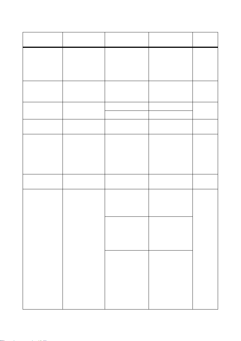
12 Parameters SMA America, LLC
Parameters Description Value/range Explanation Default
value
PVStrT Timer: target status
1 s … 1 800 s ‒ 180 s
switches from
"Wait-PV" to
"Grid-Connect"
when timer expires
PvVtgStrLevMin Limiting value for
0 V … 700 V ‒ 390 V
switching to feed-in
operation
Q-EnaTmsVtg* Connection delay
of line voltage
Q-VAr Reactive power in
kVAr
Q-VArGra* Definition of the
change of the
reactive power
target value in the
Off ‒ Off
On ‒
− 220 kVAr …
‒0kVAr
220 kVAr
0% … 100% The value
corresponds to the
nominal power
"Pmax".
1%
event of a voltage
step
Q-VArGraNom* Reactive power
0%/V … 10%/V ‒ 1%/V
gradient
Q-VArMod* Specification of the
procedure for
reactive power
regulation
Off Reactive power
0kVAr
Displacement power
factor cos φ=1
Off
VArCtlCom Limits reactive power
via an external
control unit, such as
the Power Reducer
Box
PFCtlCom Specifies the
displacement power
factor cos φ and the
excitation of the
displacement power
factor via an
external control unit,
such as the Power
Reducer Box
70 SC500HEUS-eng-BE-BUS120320 Operating Manual
Page 71

SMA America, LLC 12 Parameters
Parameters Description Value/range Explanation Default
value
VArCnst Specifies the
reactive power in
kVAr via the
parameter "Q-VAr"
VArCnstNom Specifies the
reactive power in %
via the parameter
"Q-VArNom"
VArCnstNomAnIn Specifies the
reactive power via a
control unit at the
analog input
"QExlSpnt"
PFCnst Manual input of the
displacement power
factor cos φ and the
excitation of the
displacement power
factor via the
parameters "PF-PF"
and "PF-PFExt"
PFCnstAnIn Specifies the
displacement power
factor cos φ via a
control unit at the
analog input
"QExlSpnt"
PFCtlW Specifies the
displacement power
factor cos φ
depending on the
feed-in capacity
VArCtlVol Specifies the
reactive power
depending on the
line voltage
Operating Manual SC500HEUS-eng-BE-BUS120320 71
Page 72

12 Parameters SMA America, LLC
Parameters Description Value/range Explanation Default
value
VArCtlVolHystDb Specifies the
reactive power
depending on the
line voltage
(Q = f(U)
characteristic curve)
Q-VArNom Reactive power in %− 100% … 100% ‒ 0%
Q-VArTmsSpnt* Time setting of the
1 s … 60 s ‒ 10 s
characteristic curve
point
Q-VArTmsVtg* Delay of line
1 s … 60 s ‒ 10 s
voltage
Q-VDif* Definition of the
voltage change that
leads to a reactive
power change.
Q-VDifTm* Time span in which
0.1% … 10% The value
corresponds to the
nominal voltage
"VRtg".
0 s … 120 s ‒ 1 s
1%
a voltage change
must be present
before the reactive
power target value
"Q-VArGra"
changes.
Q-VolNomP1* Voltage at point 1 80% … 120% ‒ 100%
Q-VolNomP2* Voltage at point 2 80% … 120% ‒ 100%
Q-VolWidNom* Voltage width 0% … 20% ‒ 0%
Q-VRtgOfsNom* Changes the
nominal voltage
"VRtg" of the
voltage-dependent
reactive power
− 10% … 10% The parameter is
active only if the
parameter "QVArMod" is set to
"VArCtlVol".
0%
regulation
Qlimit** The reactive power
of the
0kVAr…
1000kVAr
‒ 220 kVAr
Sunny Central
72 SC500HEUS-eng-BE-BUS120320 Operating Manual
Page 73

SMA America, LLC 12 Parameters
Parameters Description Value/range Explanation Default
value
Qmax* Limitation of the
reactive power of
0kVAr…
1000kVAr
‒ 220 kVAr
the Sunny Central
Serial Number** Inverter serial
0 … 2147483647 ‒ ‒
number
SpntRemEna Enables the plant
remotely
VArGra* Gradient of reactive
Off Deactivated On
On Activated
0% … 100% ‒ 1%
power change
(VAr/s)
VCtlhLim*** Limiting value for
overvoltage
tripping level 1
VCtlhhLim*** Limiting value for
100% … 150% Changing this
110%
parameter results in
the loss of UL
100% … 150% 120%
certification.
overvoltage
tripping level 2
VCtlhLimTm*** Tripping time for
overvoltage level 1
VCtlhhLimTm*** Tripping time for
overvoltage level 2
VCtllLim*** Limiting value for
0ms …
1 000 ms
1 000 000 ms
0ms …
160 ms
1 000 000 ms
0% … 100% 88%
undervoltage
tripping level 1
VCtlllLim*** Limiting value for
0% … 100% 50%
undervoltage
tripping level 2
VCtllLimTm*** Tripping time for
undervoltage
0ms …
1 000 000 ms
2000ms
level 1
VCtlllLimTm*** Tripping time for
undervoltage
0ms …
1 000 000 ms
160 ms
level 2
VCtlOpMinNom* Minimum
0% … 100% ‒ 95%
connection voltage
VCtlOpMaxNom*
Maximum
100% … 200% ‒ 106%
connection voltage
Operating Manual SC500HEUS-eng-BE-BUS120320 73
Page 74

12 Parameters SMA America, LLC
Parameters Description Value/range Explanation Default
value
VRtg** Nominal line
1 V … 70 000 V ‒ 200 V
voltage of the
power distribution
grid
* These parameters can only be changed after the installer password has been entered.
** These are read‑only parameters.
*** Changing this parameter results in the loss of UL certification.
74 SC500HEUS-eng-BE-BUS120320 Operating Manual
Page 75

SMA America, LLC 12 Parameters
12.2 Parameters by Topic
12.2.1 Parameters for Active Power Limitation
Parameters Description Value/range Explanation Default
P-WMod* Procedure selection
for active power
limitation
P-W Limits the active
power in kW
P-WNom Limits the active
power in %
Plimit** Nominal power of
the Sunny Central
Off Limits active power
to "Pmax"
WCtlCom Limits active power
via an external
control unit, such as
the Power Reducer
Box
WCnst Manually limits the
active power in kW
(P-W) via
communication
devices such as the
Sunny WebBox
WCnstNom Manually limits the
active power in %
(P-WNom) via
communication
devices such as the
Sunny WebBox
WCnstNomAnIn Limits active power
in % on the analog
input
0 kW … 500 kW The active power
cannot exceed
"Pmax".
0% … 100% ‒ 100%
0kW…1000kW ‒ 500 kW
value
WCnst
500 kW
Operating Manual SC500HEUS-eng-BE-BUS120320 75
Page 76

12 Parameters SMA America, LLC
Parameters Description Value/range Explanation Default
value
Pmax* Limitation of the
0 kW … 500 kW ‒ 500 kW
nominal power of
the Sunny Central
* This parameter can only be changed after the installer password has been entered.
** This is a read‑only parameter.
76 SC500HEUS-eng-BE-BUS120320 Operating Manual
Page 77
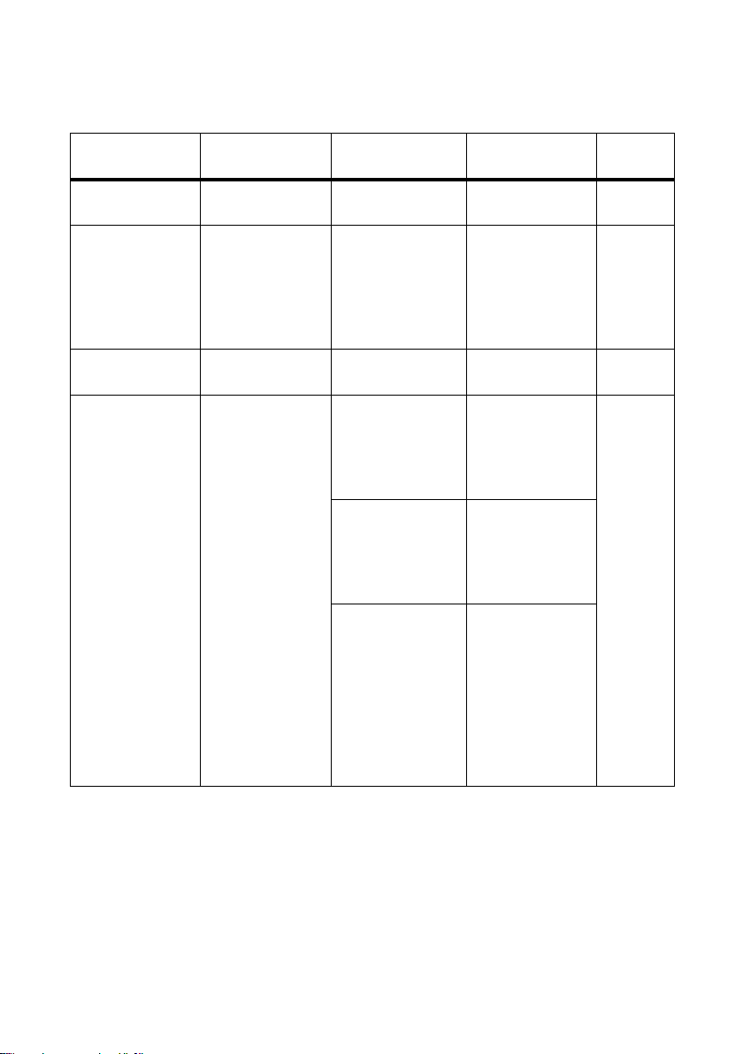
SMA America, LLC 12 Parameters
12.2.2 Parameters for Reactive Power Regulation
Parameters Description Value/range Explanation Default
value
Q-VAr Reactive power in
kVAr
Q-VArGra* Definition of the
change of the
reactive power
target value in the
event of a voltage
step
Q-VArGraNom* Reactive power
gradient
Q-VArMod* Specification of the
procedure for
reactive power
regulation
− 220 kVAr …
‒0kVAr
220 kVAr
0% … 100% The value
1%
corresponds to the
nominal power
"Pmax"
0%/V … 10%/V ‒ 1%/V
Off Reactive power
Off
0kVAr
Displacement
power factor
cos φ=1
VArCtlCom Limits reactive
power via an
external control
unit, such as the
Power Reducer Box
PFCtlCom Specifies the
displacement
power factor cos φ
and the excitation
of the displacement
power factor via an
external control
unit, such as the
Power Reducer Box
Operating Manual SC500HEUS-eng-BE-BUS120320 77
Page 78

12 Parameters SMA America, LLC
Parameters Description Value/range Explanation Default
value
VArCnst Specifies the
reactive power in
kVAr via the
parameter "Q-VAr"
VArCnstNom Specifies the
re act ive pow er i n %
via the parameter
"Q-VArNom"
VArCnstNomAnIn Specifies the
reactive power via
a control unit at the
analog input
"QExlSpnt"
PFCnst Manual input of the
displacement
power factor cos φ
and the excitation
of the displacement
po wer fac tor via the
parameters "PF-PF"
and "PF-PFExt"
PFCnstAnIn Specifies the
displacement
power factor cos φ
via a control unit at
the analog input
"QExlSpnt"
PFCtlW Specifies the
displacement
power factor cos φ
depending on the
feed-in capacity
VArCtlVol Specifies the
reactive power
depending on the
line voltage
78 SC500HEUS-eng-BE-BUS120320 Operating Manual
Page 79

SMA America, LLC 12 Parameters
Parameters Description Value/range Explanation Default
value
VArCtlVolHystDb Specifies the
reactive power
depending on the
line voltage
(Q = f(U)
characteristic curve)
Q-VArNom Reactive power in %− 100% … 100% ‒ 0%
Q-VArTmsSpnt* Time setting of the
1 s … 60 s ‒ 10 s
characteristic curve
point
Q-VArTmsVtg* Delay of line
1 s … 60 s ‒ 10 s
voltage
Q-VDif* Definition of the
voltage change that
leads to a reactive
power change.
Q-VDifTm* Time span in which
0.1% … 10% The value
corresponds to the
nominal voltage
"VRtg".
0 s … 120 s ‒ 1 s
1%
a voltage change
must be present
before the reactive
power target value
"Q-VArGra"
changes.
Q-VolNomP1* Voltage at point 1 80% … 120% ‒ 100%
Q-VolNomP2* Voltage at point 1 80% … 120% ‒ 100%
Q-VolWidNom* Voltage width 0% … 20% ‒ 0%
Q-VRtgOfsNom* Changes the
nominal voltage
"VRtg" of the
voltage-dependent
reactive power
− 10% … 10% The parameter is
active only if the
parameter
"Q-VArMod" is set
to "VArCtlVol".
0%
regulation
Qlimit** Definition of the
reactive power of
0kVAr…
1000kVAr
‒220kVAr
the Sunny Central
Operating Manual SC500HEUS-eng-BE-BUS120320 79
Page 80

12 Parameters SMA America, LLC
Parameters Description Value/range Explanation Default
value
Qmax* Limitation of the
reactive power of
0kVAr…
1000kVAr
‒220kVAr
the Sunny Central
VArGra* Gradient of reactive
0% … 100% ‒ 1%
power change
(VAr/s)
PF-PF Displacement
power factor cos φ
0.9 … 1 The lower limit is
defined by the
1
parameter
"PFAbsMin".
PF-PFExt Excitation of the
displacement
power factor cos φ
PF-PFExtStr* Excitation of the
displacement
power factor cos φ
OvExt Overexcited OvExt
UnExt Underexcited
OvExt Overexcited UnExt
UnExt Underexcited
at characteristic
curve point 1
PF-PFExtStop* Excitation of the
displacement
power factor cos φ
OvExt Overexcited OvExt
UnExt Underexcited
at characteristic
curve point 2
PF-PFStr* Displacement
power factor cos φ
at characteristic
curve point 1
PF-PFStop* Displacement
power factor cos φ
at characteristic
curve point 2
PF-WStr* Sets the feed-in
0.5 … 1 The lower limit is
0.9
defined by the
parameter
"PFAbsMin".
0.5 … 1 The lower limit is
0.9
defined by the
parameter
"PFAbsMin".
0% … 90% ‒ 0%
capacity in % at
characteristic curve
point 1
PF-WStop* Sets the feed-in
10% … 100% ‒ 100%
capacity in % at
characteristic curve
point 2
80 SC500HEUS-eng-BE-BUS120320 Operating Manual
Page 81

SMA America, LLC 12 Parameters
Parameters Description Value/range Explanation Default
value
PFAbsMin** Limitation of the
0.5 … 1 ‒ 0.9
displacement
power factor cos φ
Q-EnaTmsVtg* Connection delay
of line voltage
* This parameter can only be changed after the installer password has been entered.
** This is a read‑only parameter.
Off ‒ Off
On ‒
12.2.3 Parameters for Grid Monitoring
Loss of UL certification
The limiting values for the line voltage and the power frequency are configured in accordance
with IEEE 1547. Changes to the factory-configured limiting values result in the loss of UL
certification. The parameters for these limiting values are marked with ***.
• If the UL certification is the deciding factor for the operation permission of the inverter, do
not make any changes to the factory-configured limiting values for the grid monitoring
parameters.
Parameters Description Value/range Explanation Default
value
HzCtlhLim*** Overfrequency
limiting value
level 1
60.5 Hz … 64.5 Hz Changing this
parameter results in
the loss of UL
60.5 Hz
certification.
HzCtlhhLim* Overfrequency
60 Hz … 66 Hz ‒ 65 Hz
limiting value
level 2
HzCtlhLimTm*** Tripping time for
overfrequency
level 1
0ms …
1 000 000 ms
Changing this
parameter results in
the loss of UL
160 ms
certification.
HzCtlhhLimTm* Tripping time for
overfrequency
0ms …
1 000 000 ms
‒ 100 ms
level 2
HzCtllLim* Underfrequency
57 Hz … 59.8 Hz ‒ 59.3 Hz
limiting value
level 1
Operating Manual SC500HEUS-eng-BE-BUS120320 81
Page 82

12 Parameters SMA America, LLC
Parameters Description Value/range Explanation Default
value
HzCtlllLim*** Underfrequency
limiting value
level 2
57 Hz … 59.8 Hz Changing this
parameter results in
the loss of UL
57 Hz
certification.
HzCtllLimTm* Tripping time for
underfrequency
160 ms …
300 000 ms
‒ 160 ms
level 1
HzCtlllLimTm*** Tripping time for
underfrequency
level 2
0ms …
1 000 000 ms
Changing this
parameter results in
the loss of UL
160 ms
certification.
HzCtlOpMax* Maximum
60 Hz … 66 Hz ‒ 60.5 Hz
connection
frequency
HzCtlOpMin* Minimum
54 Hz … 60 Hz ‒ 59.3 Hz
connection
frequency
VRtg** Nominal line
1 V … 70 000 V ‒ 200 V
voltage of the
power distribution
grid
VCtlhLim*** Limiting value for
overvoltage
tripping level 1
VCtlhhLim*** Limiting value for
overvoltage
tripping level 2
VCtlhLimTm*** Tripping time for
overvoltage level 1
VCtlhhLimTm*** Tripping time for
overvoltage level 2
VCtllLim*** Limiting value for
undervoltage
tripping level 1
VCtlllLim*** Limiting value for
undervoltage
tripping level 2
100% … 150% The value is based
110%
on the nominal
voltage of the
100% … 150% 120%
inverter. Changing
this parameter
results in the loss of
UL certification.
0ms …
1 000 000 ms
0ms …
1 000 000 ms
0% … 100% The value is based
Changing this
parameter results in
the loss of UL
certification.
1 000 ms
160 ms
88%
on the nominal
voltage of the
0% … 100% 50%
inverter. Changing
this parameter
results in the loss of
UL certification.
82 SC500HEUS-eng-BE-BUS120320 Operating Manual
Page 83

SMA America, LLC 12 Parameters
Parameters Description Value/range Explanation Default
value
VCtllLimTm*** Tripping time for
undervoltage
level 1
VCtlllLimTm*** Tripping time for
undervoltage
0ms …
1 000 000 ms
0ms …
1 000 000 ms
Changing this
parameter results in
the loss of UL
certification.
2 000 ms
160 ms
level 2
VCtlOpMinNom* Minimum
0% … 100% ‒ 95%
connection voltage
VCtlOpMaxNom* Maximum
100% … 200% ‒ 106%
connection voltage
* This parameter can only be changed after the installer password has been entered.
** This is a read‑only parameter.
*** Changing this parameter results in the loss of UL certification.
12.2.4 Parameters for Grid Support
Loss of UL certification
Deactivation of the islanding detection results in the loss of UL certification and SMA is not
liable for any resulting damage.
Parameters Description Value/range Explanation Default
value
EnaAid*
Enables islanding
detection
* This parameter can only be changed after the installer password has been entered.
Operating Manual SC500HEUS-eng-BE-BUS120320 83
Off Deactivated On
On Activated
Page 84

12 Parameters SMA America, LLC
12.2.5 Device-Internal Parameters
Parameters Description Value/range Explanation Default
value
Ackn Confirms error ‒‒‒, Ackn, NoAckn ‒ ‒‒‒
CardFunc* Functions of the
memory card
CntRs* Resets meter ‒‒‒ ‒ ‒‒‒
Dt Date ‒ Format yyyymmdd ‒
‒‒‒ ‒ ‒‒‒
ForcedWrite Card logout
StoEvtHis Writes event history
to memory card
StoFailHis Writes error history
to memory card
CntFanHs Operating hour
meter of the heat
sink fan
CntFanTrf1 Operating hour
meter of transformer
fan 1
CntFanTrf2 Operating hour
meter of transformer
fan 2
CntFanCab1 Operating hour
meter of interior
fan 1
CntFanCab2 Operating hour
meter of interior
fan 2
CntHtCab Operating hour
meter of interior
heater
CntAcSw Meter for the
switching
operations of the
AC contactor
CntDcSw Meter for the
switching
operations of the
DC contactor
84 SC500HEUS-eng-BE-BUS120320 Operating Manual
Page 85

SMA America, LLC 12 Parameters
Parameters Description Value/range Explanation Default
value
Ofs_CntFanCab1 * Offset for operating
hours of internal
fan 1
Ofs_CntFanCab2* Offset for operating
hours of internal
fan 2
Ofs_CntFanHs* Offset for operating
hours of heat sink
fan
Ofs_CntFanTrf1* Offset for operating
hours of transformer
fan 1
Ofs_CntFanTrf2* Offset for operating
0 h … 2 147 483 h Changing these
parameters may be
necessary if you
0 h … 2 147 483 h ‒
replace the
operation control
unit of the Sunny
0 h … 2 147 483 h ‒
Central and wish to
transfer the data
from the old device.
You can only view
0 h … 2 147 483 h ‒
and change these
parameters using
an installer
0 h … 2 147 483 h ‒
password.
‒
hours of transformer
fan 2
Ofs_CntHtCab* Offset for operating
0 h … 2 147 483 h ‒
hours of interior
heater
Ofs_E-Total* Offset for total
energy yield of the
0kWh…
214 748 364 kWh
‒
Sunny Central
Ofs_h-On* Offset for total
0 h … 2 147 483 h ‒
operating hours of
the Sunny Central
Ofs_h-Total* Offset for total feed-
0 h … 2 147 483 h ‒
in hours of the
Sunny Central
PvPwrMinTr Limiting value for
0 kW … 1200 kW ‒ 20 kW
starting the MPP
tracker
PvPwrMinTrT Timeout for starting
1 s … 1 800 s ‒ 600 s
the MPP tracker
PVStrT Timer: target status
1 s … 1 800 s ‒ 180 s
switches from
"Wait-PV" to
"Grid-Connect"
when timer expires
Operating Manual SC500HEUS-eng-BE-BUS120320 85
Page 86

12 Parameters SMA America, LLC
Parameters Description Value/range Explanation Default
value
PvVtgStrLevMin Limiting value for
0 V … 700 V ‒ 390 V
switching to feed-in
operation
Serial Number** Inverter serial
0 … 2147483647 ‒ ‒
number
SpntRemEna Enables the plant
remotely
* This parameter can only be changed after the installer password has been entered.
** This is a read‑only parameter.
Off Deactivated On
On Activated
86 SC500HEUS-eng-BE-BUS120320 Operating Manual
Page 87

SMA America, LLC 13 Contact
13 Contact
If you have technical problems concerning our products, contact the SMA Service Line. We require
the following information in order to provide you with the necessary assistance:
• Type of inverter
• Type and number of display modules connected
•Communication method
• Sunny Central error or warning number
• Sunny Central display message
SMA Solar Technology America, LLC
6020 West Oaks Blvd, Ste 300
Rocklin, CA 95765
Tel. +1 916 625 0870
Tel. +1 877-MY SMA TECH
Tel. +1 877 697 6283 (Toll free, available for USA, Canada and Puerto Rico)
Fax +1 916 625 0871
Service@SMA-America.com
www.SMA-America.com
SMA Solar Technology Canada Inc.
2425 Matheson Blvd. E, 8th Floor
Mississauga, ON L4W 5K5
Canada
Tel. +1 877 506 1756 (Toll free, available for Canada)
Service@SMA-Canada.ca
www.SMA-Canada.ca
Operating Manual SC500HEUS-eng-BE-BUS120320 87
Page 88

XXX4."4PMBSDPN
4."4PMBS5FDIOPMPHZ
4.""NFSJDB--$
XXX4.""NFSJDBDPN
 Loading...