

Page 1
EN
Central inverter
SUNNY CENTRAL
500HE/630HE/720HE/760HE/800HE
Installation Manual
SCxxxHE-20-IA-IEN111210 | 98-40005110 | Version 1.0
Page 2

Page 3

SMA Solar Technology AG Table of Contents
Table of Contents
1 Information on this Manual. . . . . . . . . . . . . . . . . . . . . . . . . 7
2 Security . . . . . . . . . . . . . . . . . . . . . . . . . . . . . . . . . . . . . . . . . 9
2.1 Intended Use. . . . . . . . . . . . . . . . . . . . . . . . . . . . . . . . . . . . . . . . 9
2.2 Safety Instructions . . . . . . . . . . . . . . . . . . . . . . . . . . . . . . . . . . . 10
2.3 Skilled Workers Qualification. . . . . . . . . . . . . . . . . . . . . . . . . . 12
3 Product Description . . . . . . . . . . . . . . . . . . . . . . . . . . . . . . 13
3.1 Sunny Central . . . . . . . . . . . . . . . . . . . . . . . . . . . . . . . . . . . . . . 13
3.1.1 Design and Function of the Sunny Central . . . . . . . . . . . . . . . . . . . . . . . . . . 13
3.1.2 Serial Number and Device Type. . . . . . . . . . . . . . . . . . . . . . . . . . . . . . . . . . 15
3.1.3 Symbols on the Sunny Central . . . . . . . . . . . . . . . . . . . . . . . . . . . . . . . . . . . 15
3.1.4 Touch Display . . . . . . . . . . . . . . . . . . . . . . . . . . . . . . . . . . . . . . . . . . . . . . . . 16
3.1.5 Indicator lights. . . . . . . . . . . . . . . . . . . . . . . . . . . . . . . . . . . . . . . . . . . . . . . . 16
3.1.6 Quick-Stop . . . . . . . . . . . . . . . . . . . . . . . . . . . . . . . . . . . . . . . . . . . . . . . . . . 17
3.1.7 Key Switch . . . . . . . . . . . . . . . . . . . . . . . . . . . . . . . . . . . . . . . . . . . . . . . . . . 17
3.2 Sunny Central Communication Controller. . . . . . . . . . . . . . . . . 18
4 Delivery. . . . . . . . . . . . . . . . . . . . . . . . . . . . . . . . . . . . . . . . 19
4.1 Check for Transport Damage . . . . . . . . . . . . . . . . . . . . . . . . . . 19
4.2 Scope of Delivery . . . . . . . . . . . . . . . . . . . . . . . . . . . . . . . . . . . 19
5 Storage . . . . . . . . . . . . . . . . . . . . . . . . . . . . . . . . . . . . . . . . 21
6 Preparation for Installation . . . . . . . . . . . . . . . . . . . . . . . . 22
6.1 Installation Site Requirements . . . . . . . . . . . . . . . . . . . . . . . . . . 22
6.1.1 Dimensions of the Sunny Central. . . . . . . . . . . . . . . . . . . . . . . . . . . . . . . . . . 22
6.1.2 Ambient Conditions. . . . . . . . . . . . . . . . . . . . . . . . . . . . . . . . . . . . . . . . . . . . 22
6.1.3 Minimum Clearances . . . . . . . . . . . . . . . . . . . . . . . . . . . . . . . . . . . . . . . . . . 23
6.1.4 Requirements for Cable Routing . . . . . . . . . . . . . . . . . . . . . . . . . . . . . . . . . . 26
6.1.5 Requirements for cable routing between inverter and transformer . . . . . . . . 27
Installation Manual SCxxxHE-20-IA-IEN111210 3
Page 4

Table of Contents SMA Solar Technology AG
6.2 Preparing the Station Floor for Installation . . . . . . . . . . . . . . . . 28
6.2.1 Position of the mounting holes for the Sunny Central . . . . . . . . . . . . . . . . . . 28
6.2.2 Drilling mounting holes in the station floor . . . . . . . . . . . . . . . . . . . . . . . . . . 28
7 Transporting the Sunny Central . . . . . . . . . . . . . . . . . . . . 29
7.1 Center of gravity of the inverter . . . . . . . . . . . . . . . . . . . . . . . . 29
7.2 Transporting the Sunny Central with a Forklift . . . . . . . . . . . . . 30
7.3 Mounting the kick plates at the rear of the inverter. . . . . . . . . . 30
7.4 Transporting the Sunny Central with a Pallet Truck. . . . . . . . . . 31
7.5 Transporting the Sunny Central with a Crane . . . . . . . . . . . . . . 32
8 Installation of the Sunny Central. . . . . . . . . . . . . . . . . . . . 34
8.1 Sealing the exhaust air zone . . . . . . . . . . . . . . . . . . . . . . . . . . 34
8.2 Fastening the Inverter on the Foundation . . . . . . . . . . . . . . . . . 34
8.3 Disassembling the Panels . . . . . . . . . . . . . . . . . . . . . . . . . . . . . 34
8.4 Removing the Transport Lock from the Inverter Cabinet . . . . . . 35
9 AC and DC Connection . . . . . . . . . . . . . . . . . . . . . . . . . . . 36
9.1 Safety during Cable Connection . . . . . . . . . . . . . . . . . . . . . . . 36
9.2 Connection Options . . . . . . . . . . . . . . . . . . . . . . . . . . . . . . . . . 36
9.3 Connection area . . . . . . . . . . . . . . . . . . . . . . . . . . . . . . . . . . . . 37
9.3.1 DC Fuses . . . . . . . . . . . . . . . . . . . . . . . . . . . . . . . . . . . . . . . . . . . . . . . . . . . . 37
9.3.2 DC Busbar. . . . . . . . . . . . . . . . . . . . . . . . . . . . . . . . . . . . . . . . . . . . . . . . . . . 38
9.4 Cable Connection. . . . . . . . . . . . . . . . . . . . . . . . . . . . . . . . . . . 39
9.4.1 Requirements. . . . . . . . . . . . . . . . . . . . . . . . . . . . . . . . . . . . . . . . . . . . . . . . . 39
9.4.2 Cleaning the contact surfaces of terminal lugs and
connection lugs . . . . . . . . . . . . . . . . . . . . . . . . . . . . . . . . . . . . . . . . . . . . . . . 39
9.4.3 Connecting cables with 1 terminal lug . . . . . . . . . . . . . . . . . . . . . . . . . . . . . 40
9.4.4 Connecting cables with 2 terminal lugs . . . . . . . . . . . . . . . . . . . . . . . . . . . . 41
9.5 Connecting the PE cables . . . . . . . . . . . . . . . . . . . . . . . . . . . . . 42
4 SCxxxHE-20-IA-IEN111210 Installation Manual
Page 5

SMA Solar Technology AG Table of Contents
9.6 Connecting the DC cables . . . . . . . . . . . . . . . . . . . . . . . . . . . . 42
9.6.1 Requirements. . . . . . . . . . . . . . . . . . . . . . . . . . . . . . . . . . . . . . . . . . . . . . . . . 42
9.6.2 Connecting the SMB Connection Kit. . . . . . . . . . . . . . . . . . . . . . . . . . . . . . . 42
9.6.3 Connecting the DC Cables . . . . . . . . . . . . . . . . . . . . . . . . . . . . . . . . . . . . . . 43
9.7 Connecting the AC Cables . . . . . . . . . . . . . . . . . . . . . . . . . . . . 44
9.8 Mounting the kick plates. . . . . . . . . . . . . . . . . . . . . . . . . . . . . . 44
10 Cable Connection in the Connection Cabinet . . . . . . . . . 45
10.1 Connection area . . . . . . . . . . . . . . . . . . . . . . . . . . . . . . . . . . . . 45
10.2 Preparing the Cable Connection . . . . . . . . . . . . . . . . . . . . . . . 46
10.3 Leading the Cables into the Connection Cabinet . . . . . . . . . . . 47
10.4 Connecting the Cables in the Connection Cabinet. . . . . . . . . . 48
10.4.1 Connecting the cables to the customer terminal block . . . . . . . . . . . . . . . . . 48
10.4.2 Important Measures for Non-utilized Options. . . . . . . . . . . . . . . . . . . . . . . . 48
10.4.3 Connecting the Sunny String-Monitor . . . . . . . . . . . . . . . . . . . . . . . . . . . . . . 49
10.4.4 Connecting the Remote Shutdown . . . . . . . . . . . . . . . . . . . . . . . . . . . . . . . . 49
10.4.5 Connecting the External Target Value Specification . . . . . . . . . . . . . . . . . . . 50
10.4.6 Connecting the Transformer Protection . . . . . . . . . . . . . . . . . . . . . . . . . . . . . 51
10.4.7 Connecting the External Voltage Supply. . . . . . . . . . . . . . . . . . . . . . . . . . . . 51
10.4.8 Connecting the External Quick-Stop Cabling . . . . . . . . . . . . . . . . . . . . . . . . 52
11 Connection of the Communication Devices . . . . . . . . . . . 54
11.1 Structure of a Plant Network. . . . . . . . . . . . . . . . . . . . . . . . . . . 54
11.2 Position of the communication ports . . . . . . . . . . . . . . . . . . . . . 55
11.3 Building a Plant Network with Copper Cables. . . . . . . . . . . . . 56
11.4 Building a Plant network with Optical Fibers . . . . . . . . . . . . . . 56
12 Commissioning . . . . . . . . . . . . . . . . . . . . . . . . . . . . . . . . . . 57
12.1 Commissioning the Inverter. . . . . . . . . . . . . . . . . . . . . . . . . . . . 57
12.2 Checking the Cabling on the Inverter . . . . . . . . . . . . . . . . . . . . 58
Installation Manual SCxxxHE-20-IA-IEN111210 5
Page 6

Table of Contents SMA Solar Technology AG
12.3 Checking the Inverter Voltage. . . . . . . . . . . . . . . . . . . . . . . . . . 59
12.3.1 Checking the DC Voltages . . . . . . . . . . . . . . . . . . . . . . . . . . . . . . . . . . . . . . 59
12.3.2 Checking the AC Grid Voltage . . . . . . . . . . . . . . . . . . . . . . . . . . . . . . . . . . . 60
12.3.3 Checking the External Voltage Supply . . . . . . . . . . . . . . . . . . . . . . . . . . . . . 61
12.4 Mounting the Panels . . . . . . . . . . . . . . . . . . . . . . . . . . . . . . . . . 62
12.5 Inserting Fuses or Disconnecting Blades . . . . . . . . . . . . . . . . . . 62
12.6 Switching on the Voltage Supply . . . . . . . . . . . . . . . . . . . . . . . 63
12.7 Switching on the Inverter. . . . . . . . . . . . . . . . . . . . . . . . . . . . . . 64
13 Decommissioning . . . . . . . . . . . . . . . . . . . . . . . . . . . . . . . . 65
14 Technical Data . . . . . . . . . . . . . . . . . . . . . . . . . . . . . . . . . . 66
14.1 Sunny Central 500HE. . . . . . . . . . . . . . . . . . . . . . . . . . . . . . . . 66
14.2 Sunny Central 630HE. . . . . . . . . . . . . . . . . . . . . . . . . . . . . . . . 67
14.3 Sunny Central 720HE. . . . . . . . . . . . . . . . . . . . . . . . . . . . . . . . 68
14.4 Sunny Central 760HE. . . . . . . . . . . . . . . . . . . . . . . . . . . . . . . . 70
14.5 Sunny Central 800HE. . . . . . . . . . . . . . . . . . . . . . . . . . . . . . . . 71
15 Contact . . . . . . . . . . . . . . . . . . . . . . . . . . . . . . . . . . . . . . . . 73
6 SCxxxHE-20-IA-IEN111210 Installation Manual
Page 7
SMA Solar Technology AG 1 Information on this Manual
1 Information on this Manual
Validity
It is valid for the following device types with firmware version 01.14.12.R or higher:
• Sunny Central 500HE (SC 500HE-20)
• Sunny Central 630HE (SC 630HE-20)
• Sunny Central 720HE (SC 720HE-20)
• Sunny Central 760HE (SC 760HE-20)
• Sunny Central 800HE (SC 800HE-20)
Target Group
This manual is intended for skilled workers. Only qualified personnel are allowed to perform the tasks
set forth in this manual (see section 2.3"Skilled Workers Qualification",page12).
Additional Information
Additional information is available at www.SMA.de/en:
Information Document type
Installation requirements for Sunny Central 500HE/630HE/
720HE/760HE/800HE
Medium-voltage Transformers − Important requirements for
medium-voltage transformers for Sunny Central of the HE and
CP range.
COM-B − Communication distributor for large-scale plants with
Sunny Central, Sunny Mini Central or Sunny Tripower
Sunny Main Box ‒ Connecting the DC cabling for PV inverters Technical information
Technical information
Technical information
Technical information
Installation Manual SCxxxHE-20-IA-IEN111210 7
Page 8
1 Information on this Manual SMA Solar Technology AG
%"/(&3
8"3/*/(
$"65*0/
/05*$&
Symbols
Symbol Explanation
Indicates a hazardous situation which, if not avoided, will result in death or
serious injury.
Indicates a hazardous situation which, if not avoided, could result in death or
serious injury.
Indicates a hazardous situation which, if not avoided, could result in minor or
moderate injury.
Indicates a situation that can result in property damage if not avoided.
Indicates information that is important for a specific topic or objective, but is
not safety-relevant.
☐ Indicates a requirement for meeting a specific goal.
☑ Desired result.
✖ Undesired result. Followed by a solution on how to achieve the desired result.
Typography
Typography Usage Example
"light" • Display messages
• Parameters
• Terminals
•Sockets
bold • Elements which you should
select
• Elements which you should enter
• The inverter switches into the
"Waiting" operating state.
• Set parameter "FanTest" to 1.
Nomenclature
In this manual, the Sunny Central of the HE series is referred to as Sunny Central or inverter.
In this manual, the Sunny Central Communication Controller is also referred to as SC-COM.
8 SCxxxHE-20-IA-IEN111210 Installation Manual
Page 9

SMA Solar Technology AG 2 Security
A
B
C
D
E
S
M
A
S
M
A
H
E
2Security
2.1 Intended Use
The Sunny Central is a central inverter which converts the direct current from PV modules into
alternating current. Here, the maximum permissible DC input voltage must not be exceeded.
The Sunny Central is suitable for indoor installation, providing that the specified safety distances are
complied with. The enclosure complies with the IP21 protection class. IP21 means that the closed
inverter is protected against vertically falling dripping water. The inverter is classified under
Class 3 C1L according to EN 60721-3-3.
Inverters of the HE series may only be operated in connection with a suitable transformer.
The transformer must be designed for the voltages that arise during pulsed operation of the inverter.
The voltages can reach a magnitude of maximum ±1 450 V to ground. (see Technical Information
"Medium-voltage Transformer" at www.SMA.de/en).
Do not switch off or change s ettings th at affe ct gri d management without first obtaining approval from
the distribution grid operator.
Figure1: Principle of a grid-tie PV plant with an inverter
Position Description
APV modules
B Sunny String-Monitor
C Sunny Central
D Medium-voltage Transformers
E Power distribution grid
Installation Manual SCxxxHE-20-IA-IEN111210 9
Page 10

2 Security SMA Solar Technology AG
2.2 Safety Instructions
Electrical Risk
Risk of electric shock when touching conductive parts
High voltages that can cause electrical shocks are present in the inverter. Work on the inverter is only
allowed if the power is disconnected and in compliance with the guidelines that apply at the
installation location.
• Disconnect the following components:
– Grid voltage for grid feeding
– Internal supply
–DC voltage from the PV array
– Additional external voltages (e.g., control signals of a control room)
• Ensure that the device cannot be reconnected.
•Ensure that no voltage is present.
• Ground and short-circuit.
• Cover or safeguard any adjacent live components.
Electric shock through capacitors not fully discharged
Hazardous voltages may still be present in the inverter even if the AC and DC main switches are
switched off.
• Wait at least 12 minutes after switching off the inverter.
Electric shock caused by damage on the inverter
The operation of a damaged inverter can lead to serious or lethal injuries through electric shock.
• Operate the inverter only in technically proper and operationally safe status.
• Check the inverter regularly for visible damage.
• Ensure that all safety features are freely accessible at all times.
• Regularly check for correct functioning.
Electric shock caused by ground fault
In case of a ground fault, assume that grounded plant components are still live.
• Ensure that no voltage is present before touching.
Electric shock when entering the PV field
The insulation monitoring device with GFDI or Remote GFDI does not provide protection from injury
when GFDI is activated. PV modules grounded by means of GFDI disperse voltage to ground.
When entering the PV field, lethal electric shocks may occur.
• Before entering the PV field, switch the PV modules to insulated operation.
• Ensure that the insulation resistance of the PV field is greater than 1 k Ω .
10 SCxxxHE-20-IA-IEN111210 Installation Manual
Page 11

SMA Solar Technology AG 2 Security
Electric shock resulting from a failure to comply with safety requirements
Failure to follow this manual, the general instructions or safety instructions may lead to severe injury
due to electric shock.
• Only perform work as described in this manual. Observe all safety instructions.
• Establish all electrical connections according to the circuit diagram.
• Safely store the documentation within the immediate area of the inverter. It must be accessible
to service and maintenance personnel at all times.
Electrostatic discharge can damage electronic components
Electrostatic discharge can destroy component parts.
• During work on the inverter and handling of the components, observe the ESD protection
regulations and wear protective gloves.
• Discharge electrostatic charges through contact with unvarnished, grounded enclosure parts
(e.g., on the PE connection of the doors). Only then is it safe to touch any electronic components.
Burn Hazard
Some components, such as fuses, can become hot during operation.
• Wear safety gloves when working on the inverter.
Inverter Damage
Tampering with the device may result in plant damage.
• Do not operate the inverter while the door is open.
If the key remains in the door lock, the inverter can be opened by unauthorized persons.
• Remove the key from the door locks and from the key switch.
• Keep the keys in a safe place.
Penetrating moisture can damage the inverter.
• Do not open the inverter when it is raining or in case of humidity > 95%.
Electrostatic discharge can destroy components.
• During work on the inverter and handling of the components, observe the ESD protection
regulations and wear protective gloves.
• Discharge electrostatic charges through contact with unvarnished, grounded enclosure parts
(e.g., on the PE connection of the doors). Only then it is safe to touch any electronic components.
Warning signs must be easily readable at all times and must be replaced in the event of damage.
Hazard due to blocked escape route
Opening of the doors of 2 opposing inverters blocks the escape route. It is imperative that the escape
route is freely accessible at all times. Make sure the minimum passage width of the route meets local
standards. In Germany, the minimum passage width is 500 mm.
• Only the door of one inverter may be open at any given time.
Installation Manual SCxxxHE-20-IA-IEN111210 11
Page 12

2 Security SMA Solar Technology AG
2.3 Skilled Workers Qualification
All work on the inverter may only be carried out by qualified technical personnel. Qualified means
that the personnel has the relevant training for the tasks.
For commissioning and operating the inverter, the personnel must be familiar with the installation
manual and the user manual. Observe safety instructions.
12 SCxxxHE-20-IA-IEN111210 Installation Manual
Page 13

SMA Solar Technology AG 3 Product Description
3 Product Description
3.1 Sunny Central
3.1.1 Design and Function of the Sunny Central
The Sunny Central is a PV inverter that converts the direct current from the PV array into alternating
current for the grid.
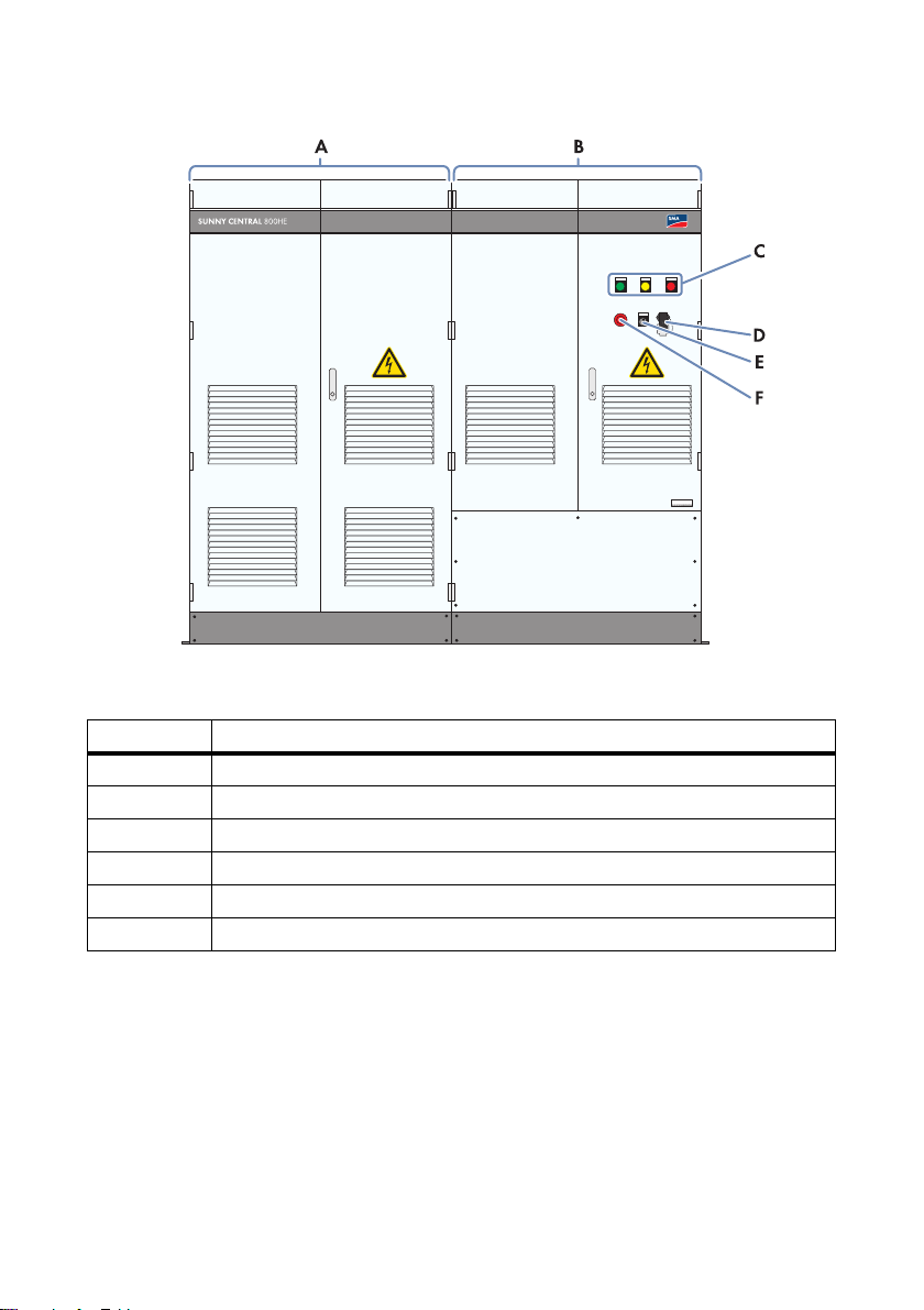
Figure2: Sunny Central, using the example of a Sunny Central 800HE with touch display
Position Description
A Inverter cabinet
B Connection cabinet
CTouch display
D Service interface
EKey Switch
FQuick-Stop
Installation Manual SCxxxHE-20-IA-IEN111210 13
Page 14
3 Product Description SMA Solar Technology AG
Figure3: Sunny Central, using the example of a Sunny Central 800HE with indicator lights
Position Description
A Inverter cabinet
B Connection cabinet
C Indicator lights
D Service interface
EKey Switch
FQuick-Stop
The Sunny Central can implement the requirements of the distribution grid operator with the aid of the
Power Reducer Box or the Sunny Central Communication Controller.
14 SCxxxHE-20-IA-IEN111210 Installation Manual
Page 15
SMA Solar Technology AG 3 Product Description
3.1.2 Serial Number and Device Type
The serial number (Serial No.) and device type (Type) of the Sunny Central are listed on the type
label. The type label is located on the inside of the right door on both the inverter cabinet and the
connection cabinet.
Reading off the serial number
You can identify the serial number without opening the inverter. The serial number is located at
the bottom right on the outside of the switch cabinet door. You can also read off the serial
number from the display.
Reading off the firmware
You can read off the version number of the firmware from the inverter and the display via the
user interface of the Sunny Central Communication Controllers or from the display.
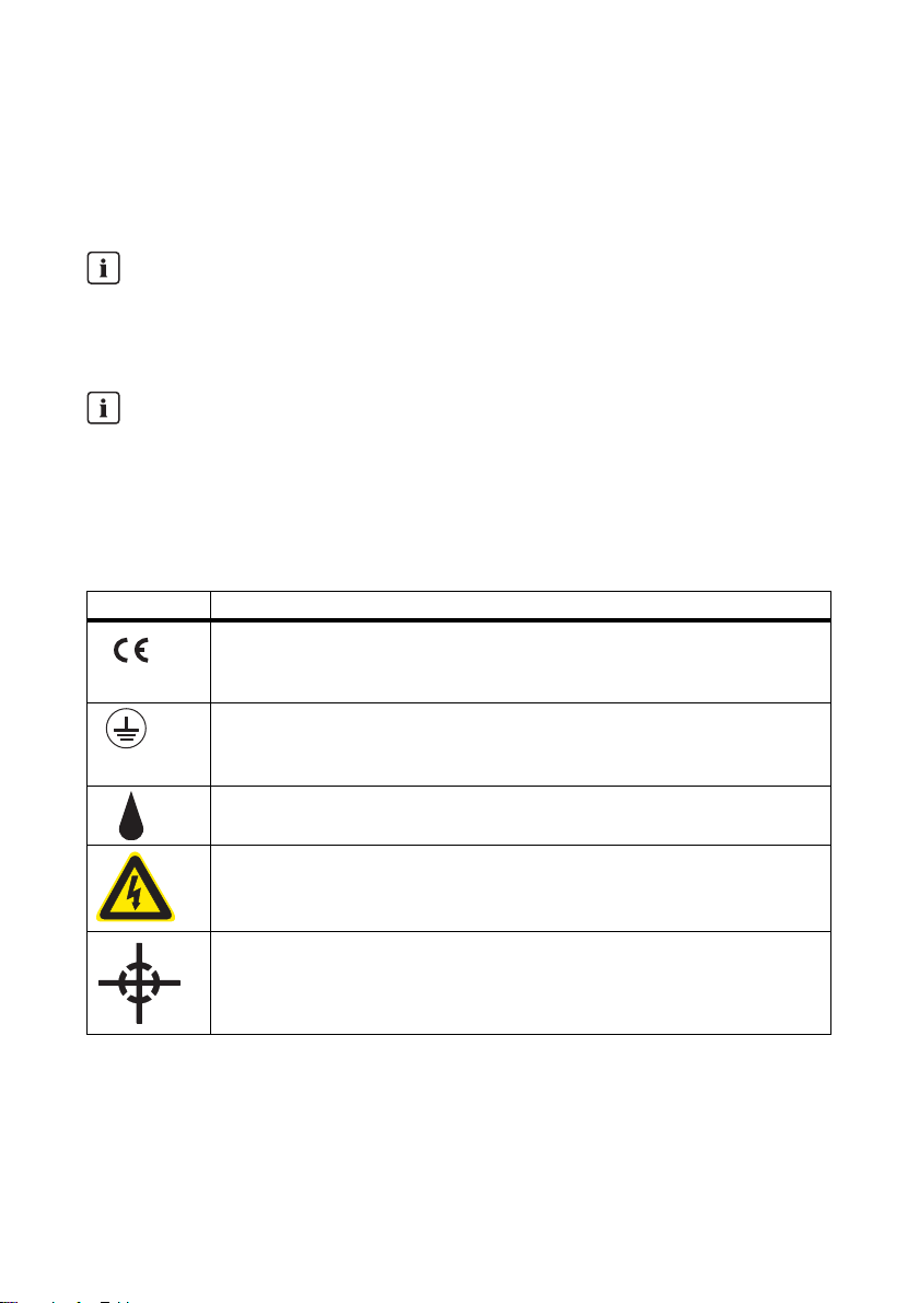
3.1.3 Symbols on the Sunny Central
All the symbols on the Sunny Central and the type label are explained below.
Symbol Description
CE mark.
The Sunny Central complies with the relevant provisions of the European
Community.
Protection class I.
All operating facilities are connected to the protective conductor system of the
Sunny Central.
Degree of protection IP 21.
The Sunny Central is protected against dripping water.
Beware of dangerous electrical voltage.
The Sunny Central operates at high voltages. All installation work on the
Sunny Central must be performed by electrically skilled persons only.
Center of gravity of the inverter.
Installation Manual SCxxxHE-20-IA-IEN111210 15
Page 16
3 Product Description SMA Solar Technology AG
3.1.4 Touch Display
Depending on which option is ordered, the Sunny Central may be equipped with a touch display.
Different kinds of inverter data can be viewed on the touch display. The touch display is only used as
a means for viewing data. The display switches off if it is inactive for more than 5 minutes. It switches
on when it is touched.
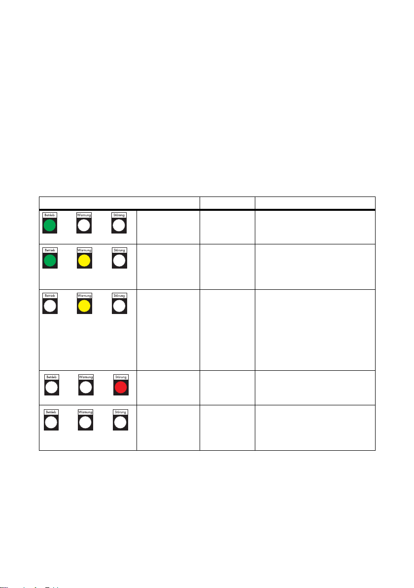
3.1.5 Indicator lights
Depen ding on whi ch options are ord ered, the Sunny Cen tral may be equipped with 3 indi cator lights.
The indicator lights show the status of the inverter.
The functions of each status are described below.
Condition Description Function
Green indicator
light glows
continuously
Yellow and green
indicator lights
glow
continuously
Yellow indicator
light glows
continuously
Red indicator
light glows
continuously
All indicator lights
are off
Feed-in
operation
Limited
operation
Warning The Sunny Central is currently not
Fault The Sunny Central has detected a
No feed-in
operation
The Sunny Central is feeding into
the power distribution grid.
The Sunny Central has detected a
warning. The warning currently
does not affect the operation of the
Sunny Central.
feeding power into the grid and
has detected a warning. It is
automatically reset as soon as the
warning is no longer present.
This status is used, for instance,
when the level of irradiation is low.
fault and is now switched off.
The Sunny Central is not feeding
into the grid, the supply voltage is
disconnected, or the key switch is
set to "Stop".
16 SCxxxHE-20-IA-IEN111210 Installation Manual
Page 17

SMA Solar Technology AG 3 Product Description
3.1.6 Quick-Stop
In case of emergency, this switch enables disconnection of the inverter from the PV array and the
medium-voltage grid within 500 ms.
Tripping the quick-stop function
The quick-stop function may only be tripped if there is imminent danger.
Pressing the quick-stop button does not trip rapid discharge of the capacitor.
Pressing the quick-stop button opens the DC contactor, switches off the inverter bridge and
disconnects the inverter from the AC grid.
3.1.7 Key Switch
The key switch is used to switch the Sunny Central on and off.
Switch position "Start"
After turning the switch to the "Start" position, the Sunny Central switches from "Stop" mode to
"Grid monitoring" mode. If there is sufficient irradiation and a valid grid connection, the Sunny Central
switches to feed-in operation. If there is insufficient irradiation, the input voltage is too low for startup,
and the Sunny Central remains in the "Grid monitoring" state.
Switch position "Stop"
If the key switch is turned to "Stop" when the Sunny Central is in the "Grid monitoring" mode, a motor
drive automatically shuts off the DC main switch. The Sunny Central goes into the "Stop" mode.
If the key switch is turned to "Stop" when the Sunny Central is in "MPP load operation", the
Sunny Central switches to the operating state "Shutdown". Once shutdown is complete, the AC
contactor and the DC main switch tur n off aut oma tic all y and the Sunny C entral goe s into "Sto p" mode.
Installation Manual SCxxxHE-20-IA-IEN111210 17
Page 18

3 Product Description SMA Solar Technology AG
HE
SUNNY CENTRAL
STRING MONITOR CONTROLLER
3.2 Sunny Central Communication Controller
The SC-COM is the central communication interface of the inverter. The SC-COM establishes the
connection between the inverter and the plant operator.
Figure4: SC-COM
The SC-COM collects all data from the connected devices. The SC-COM enables monitoring,
parameterization and remote diagnosis of the inverter via computer, as well as power regulation by
the grid operator.
These various tasks performed by the SC-COM can be organized in 2 separate networks:
• Monitoring network: takes care of the monitoring, parameterization and remote diagnosis
functions.
• Regulation network: here, the specifications issued by the distribution grid operator for grid
stability management are transmitted. Since the regulation network is used exclusively for
transmitting the data of the distribution grid operator, the specifications are made available in
the requisite time.
If there is only a low level of data flow in the monitoring network, the grid operator specifications can
also be transmitted via the monitoring network. In this case, there is no need for 2 networks.
The operator can access all data stored in the SC-COM via an Ethernet connection.
You can set the parameters of the inverter via the SC-COM.
The networks are realized on the basis of copper cables or optical fibers.
PV Plant Communication Type
The interface of the SC-COM is set by default to "COM 3". The default setting of the baud rate
for the following options is:
• Option 11/0 without hub: baud rate 115 200
• Options 11/1 and 11/2 with hub: baud rate 19 200
Do not modify these settings.
18 SCxxxHE-20-IA-IEN111210 Installation Manual
Page 19
SMA Solar Technology AG 4 Delivery
4Delivery
4.1 Check for Transport Damage
Every inverter has been thoroughly checked by SMA Solar Technology AG before leaving our
factory. Despite the robust packaging, damage can occur during shipping and transport. Carry out a
visual inspection of the inverter before installation. Should you find any visible damage, contact your
retailer and the transport company responsible for the delivery of the inverter.
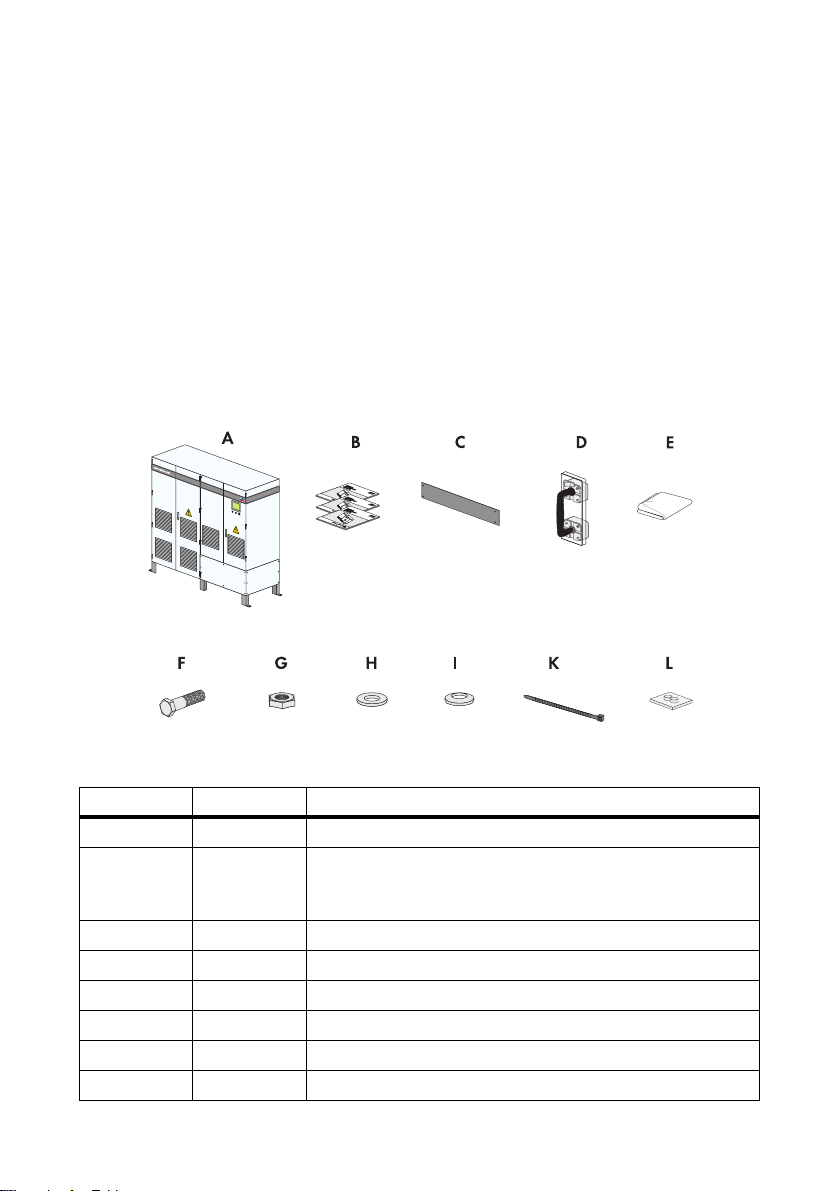
4.2 Scope of Delivery
Check the delivery for completeness and any visible external damage. Contact your retailer or the
SMA Serviceline if the delivery is incomplete or damaged.
Figure5: Delivery components
Position Quantity Description
A 1 Sunny Central
B1SMA documentation set:
installation manual, user manual, circuit diagram,
commissioning report
C6Kick plate
D1LV/HRC fuse handle
E 1 Non-woven abrasive
F34Screw
G34Nut
H 68 Fender washer
Installation Manual SCxxxHE-20-IA-IEN111210 19
Page 20

4 Delivery SMA Solar Technology AG
Position Quantity Description
I68Spring washer
K 80 Cable tie
L 3 Rubber seal (9.5 mm … 17 mm)
Position of the LV/HRC fuse handle
For order option DC fuse, the LV/HRC fuse handle is to be found on the inner side of the right
door of the connection cabinet.
20 SCxxxHE-20-IA-IEN111210 Installation Manual
Page 21

SMA Solar Technology AG 5 Storage
/05*$&
/05*$&
5Storage
If you need to store the inverter prior to final installation, note the following points:
Penetrating moisture can damage the inverter.
• Only store the inverter in a closed state.
• Storage permissible in dry, covered locations only. Observe the conditions for degree of
protection IP 21.
• Temperature at the storage location between ‒20°C … +50°C.
An uneven foundation may damage the frame construction.
• The foundation must be suitable for the weight of the inverter of 1 670 kg.
• Unevenness of the foundation max. 0.25%.
Storage in cold conditions and high humidity
If when storing the Sunny Central you connect the external voltage supply and switch on the
miniature circuit-breaker of the external voltage supply, the heater is activated automatically in
the event of high humidity. The connection of the external voltage supply is described in section
10.4.7"Connecting the External Voltage Supply",page51.
Installation Manual SCxxxHE-20-IA-IEN111210 21
Page 22

6 Preparation for Installation SMA Solar Technology AG
HE
906 mm
1 202 mm
100 mm
1 202 mm
2 404 mm
2 093 mm
6 Preparation for Installation
6.1 Installation Site Requirements
6.1.1 Dimensions of the Sunny Central
Figure6: Dimensions
Height Width Depth
2 093 mm 2 404 mm 906 mm
6.1.2 Ambient Conditions
☐ The required amount of supply air is available. If the required amount of air cannot be
guaranteed, install an extra ventilation, e.g., external fans.
☐ The installation site must be accessible at all times.
☐ The altitude of the installation site must be below the maximum installation altitude
(see section 14"Technical Data",page66).
☐ The ambient temperature must be within the operating temperature range
(see section 14"Technical Data",page66).
☐ The installation site is compliant with the requirements on ambient conditions
(see "Installation Conditions for Sunny Central 500HE/630HE/720HE/760/HE/800HE”).
22 SCxxxHE-20-IA-IEN111210 Installation Manual
Page 23
SMA Solar Technology AG 6 Preparation for Installation
8"3/*/(
/05*$&
HE
300 mm
220 mm
300 mm
1 200 mm
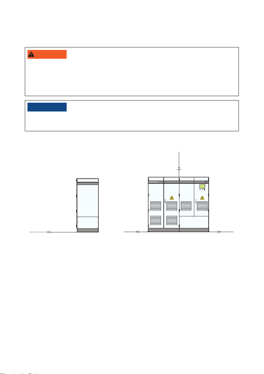
6.1.3 Minimum Clearances
Danger of fire due to overheating of cables.
Differing cable lengths result in excessive heating of the cables.
• All line conductors from the inverter to the transformer must be of the same length.
• The cable length between the connection points must not exceed a maximum of 15 m.
Damage to the inverter and transformer due to discharged air being sucked in.
• Install the plant so that the inverter cannot suck in any exhaust air.
Minimum clearance for 1 inverter
Figure7: Minimum clearances of the inverter
The exhaust air vent is located at the rear of the inverter.
For the optimum operation of the inverter, observe the following points:
Installation Manual SCxxxHE-20-IA-IEN111210 23
• Do not block or close the exhaust air vent.
• Ensure that the station is equipped with a suitable exhaust air vent.
• In order to prevent thermal short circuits in the inverter, ensure that there are exhaust air ducts
in closed rooms.
• The exhaust air vents must be accessible for cleaning at all times.
Page 24

6 Preparation for Installation SMA Solar Technology AG
A
B
Figure8: Minimum clearance for 1 inverter in an electrical equipment room
Position Description
A Minimum passage width
Maint ain the min imum pa ssage widt h between t he open door of the Sunny Cen tral
an d th e next fi xed obs tac le. The mini mum pas sag e wi dth must com ply with national
standards. In Germany, the minimum passage width is 500 mm.
BInverter
24 SCxxxHE-20-IA-IEN111210 Installation Manual
Page 25

SMA Solar Technology AG 6 Preparation for Installation
8"3/*/(
Minimum clearances for 2 inverters
Figure9: Minimum clearances for 2 inverters in an electrical equipment room
Position Description
A Minimum passage width
Maint ain the min imum pa ssage widt h between t he open door of the Sunny Cen tral
an d th e next fi xed obs tac le. The mini mum pas sag e wi dth must com ply with national
standards. In Germany, the minimum passage width is 500 mm.
BInverter
In order to comply with the escape route regulations, only one inverter may be open at a time.
Danger due to blocked escape route
Opening of the doors of 2 opposing inverters blocks the escape route. It is imperative that the
escape route is freely accessible at all times. Make sure the minimum passage width of the route
meets local standards. In Germany, the minimum passage width is 500 mm.
• Only the door of one inverter may be open at any given time.
• Observe the minimum passage width.
Installation Manual SCxxxHE-20-IA-IEN111210 25
Page 26

6 Preparation for Installation SMA Solar Technology AG
6.1.4 Requirements for Cable Routing
Laying the cables
This document does not specify at what time the cables are to be laid in the foundation.
The time for laying the cables must be decided individually for the particular plant.
☐ Cable entries are located in the connection cabinet.
☐ Empty tubes for the cable routing have been laid
under the foundation.
☐ The communication cables are separated from
the AC and DC cables.
☐ An appropriate number of cable entries
is provided:
– AC cables: 3
– DC cables: according to the number of
DC cables
–PE cables: 1
– Communication cables: 1
Figure10: Cable entries for 9 DC inputs (example)
Position Description
AEntry for AC cable
BEntry for DC cable
CEntry for PE cable
D Entry for communication cable
26 SCxxxHE-20-IA-IEN111210 Installation Manual
Page 27

SMA Solar Technology AG 6 Preparation for Installation
L2
L1
L3
L2
L1
L3
L2
L1
L3
1d
>2d
--
>2d
--
6.1.5 Requirements for cable routing between inverter and transformer
☐ The AC cables are 3-phase cables.
☐ Between the transformer and the inverter, there are 3 separate cable routes, e.g., cable
channels, for the AC cables.
☐ The spacing between the cable routes must be at least twice the diameter of an AC cable.
Figure11: Arrangement of AC cables with three cables per line conductor (example).
Observe cable clearances
Lay an L1, L2 and L3 line conductor in each cable route. The spacing between the cable pairs
must be at least twice the diameter of a cable. This prevents current imbalances.
Installation Manual SCxxxHE-20-IA-IEN111210 27
Page 28

6 Preparation for Installation SMA Solar Technology AG
2 404 mm
16 mm
906 mm
773 mm
A
A
A
A
2 470 mm
2 510 mm
6.2 Preparing the Station Floor for Installation
6.2.1 Position of the mounting holes for the Sunny Central
Before installing the inverter, prepare the mounting fixtures in the floor.
There are 4 mounting brackets in the base area of the inverter for anchoring in the foundation.
Figure12: Position of the mounting brackets on the inverter
Position Description
A Mounting brackets
6.2.2 Drilling mounting holes in the station floor
1. Mark the positions of the mounting holes on the foundation corresponding to the mounting
brackets.
2. Drill mounting holes at the marked places in the foundation.
28 SCxxxHE-20-IA-IEN111210 Installation Manual
Page 29

SMA Solar Technology AG 7 Transporting the Sunny Central
7 Transporting the Sunny Central
7.1 Center of gravity of the inverter
The center of gravity of the inverter is marked on the packaging and on the enclosure with the
appropriate symbol.
Center of gravity of the inverter
The center of gravity is not in the middle of the Sunny Central. Keep this in mind during
transportation of the Sunny Central.
Installation Manual SCxxxHE-20-IA-IEN111210 29
Page 30

7 Transporting the Sunny Central SMA Solar Technology AG
8"3/*/(
/05*$&
7.2 Transporting the Sunny Central with a Forklift
Danger of crushing if the raised Sunny Central tips over or falls during lifting.
If the inverter is raised and transported without due care or too quickly, it may tip over or fall.
• Transport the Sunny Central as close to the ground as possible at all times.
• Use all suspension points for transportation.
• Avoid fast or jerky movements with the forklift.
• Keep a safe distance from the Sunny Central at all times during transport.
• All means of transport used must be designed for the weight of th e Sunny Central of 1 670 kg.
Damage to the inverter due to inappropriate transport.
• Never place the inverter on an unstable, uneven surface, not even for a short period of time.
• Do not transport the inverter with mounted kick plates.
1. Move the forklift under the inverter from the front or
the rear. Use the fork bracket. This will prevent the
Sunny Central from slipping during transport.
2. Secure the inverter, e.g., with retaining straps, to prevent it tipping over.
3. Raise the inverter slightly.
4. Transport the inverter to the installation site.
7.3 Mounting the kick plates at the rear of the inverter
Prior to aligning the inverter on the foundation, the kick plates must be fastened in place at the rear of
the inverter.
1. Mount the kick plates at the rear of the inverter in the prescribed position.
2. Attach the kick plates to the inverter using a Torx screwdriver.
30 SCxxxHE-20-IA-IEN111210 Installation Manual
Page 31

SMA Solar Technology AG 7 Transporting the Sunny Central
8"3/*/(
/05*$&
7.4 Transporting the Sunny Central with a Pallet Truck
Danger of crushing if raised Sunny Central tips over, falls or sways during lifting.
If the inverter is raised and transported without due care or too quickly, it may tip over or fall.
• Always approach the inverter with the pallet truck from the side.
• Transport the Sunny Central as close to the ground as possible at all times.
• Use all suspension points for transportation.
• Avoid fast or jerky movements with the pallet truck.
• Keep a safe distance from the Sunny Central at all times during transport.
• All means of transport used must be designed for the weight of th e Sunny Central of 1 670 kg.
Damage to the inverter due to inappropriate transport.
• Only place the inverter on firm, level surfaces.
• Do not transport the inverter with mounted kick plate.
1. Approach the inverter with the pallet truck from the
side. This will prevent the inverter from tipping over.
2. Raise the inverter slightly.
3. Transport the inverter to the installation site.
Installation Manual SCxxxHE-20-IA-IEN111210 31
Page 32

7 Transporting the Sunny Central SMA Solar Technology AG
8"3/*/(
/05*$&
H
E
7.5 Transporting the Sunny Central with a Crane
Danger of crushing if raised Sunny Central tips over, falls or sways during lifting.
If the inverter is raised and transported without due care or too quickly, it may tip over or fall.
• Transport the Sunny Central as close to the ground as possible at all times.
• Use all suspension points for transportation.
• Use steel cables or chains with lifting hooks and shackles.
• Avoid fast or jerky movements with the crane.
• Keep a safe distance from the Sunny Central at all times during transport.
• All means of transport used must be designed for the weight of th e Sunny Central of 1 670 kg.
Damage to the inverter due to inappropriate transport.
• Put the inverter down on firm, level surfaces only.
1. Attach hooks of the steel cables/chains or lifting hook shackles to all 4 crane eyes on the
Sunny Central.
2. If the inverter is transported with the crane fork,
it must approach the inverter from the front.
32 SCxxxHE-20-IA-IEN111210 Installation Manual
Page 33

SMA Solar Technology AG 7 Transporting the Sunny Central
3. Raise the crane hook slowly until the steel cables or
chains are tensioned.
4. Ensure that all steel cables and load hooks or load beams and shackles are attached correctly.
5. Raise the inverter slightly.
6. Transport the inverter to the installation site.
Installation Manual SCxxxHE-20-IA-IEN111210 33
Page 34

8 Installation of the Sunny Central SMA Solar Technology AG
/05*$&
/05*$&
8 Installation of the Sunny Central
8.1 Sealing the exhaust air zone
When the inverter is installed in the station, the exhaust air vent of the inverter must be connected to
the exhaust air of the station. The connections between the openings must be sealed tight. This will
ensure that all the warm air exhausted from the inverter is ducted out.
Damage to the inverter due to overheating.
Non-existent or inadequate sealing between the exhaust air vent of the inverter and the exhaust air
zone of the station may result in overheating of the inverter.
• Make sure that the warm exhaust air from the inverter is ducted out. When selecting the
sealing material make sure it is suited for air temperatures of up to +70°C.
8.2 Fastening the Inverter on the Foundation
Once the inverter has been aligned on the foundation, you can fasten it in place with concrete screw
anchors.
Additional mounting material (not included in the scope of delivery):
☐ 4 suitable concrete screw anchors must be provided.
• Insert the screw anchors through the brackets on the inverter into the foundation. The exact
procedure depends on the type of screw anchors used.
8.3 Disassembling the Panels
Damage due to PE cables being ripped out.
The panels are connected to the inverter via PE cables.
• When dismantling the panels, take care not to damage the PE cables.
The panels are located in the lower section of the connection cabinet.
1. Remove the panel screws using a Torx screwdriver (T30).
2. Carefully remove the front panel of the connection area. First, pull the panel forwards by
80 mm … 100 mm.
3. Detach PE cable from the rear side of the panel.
34 SCxxxHE-20-IA-IEN111210 Installation Manual
Page 35

SMA Solar Technology AG 8 Installation of the Sunny Central
4. Remove the panels.
5. Remove the screws from the Plexiglas cover and remove the cover from the inverter.
8.4 Removing the Transport Lock from the Inverter Cabinet
Subject to the production version, the inverter power units are secured during transport with ESDprotected bubble wrap.
1. Open the inverter cabinet.
2. Remove the bubble wrap from each of the
3 inverter bridges. Observe the safety measures for
ESD protection.
3. Close the inverter cabinet.
Installation Manual SCxxxHE-20-IA-IEN111210 35
Page 36

9 AC and DC Connection SMA Solar Technology AG
9 AC and DC Connection
9.1 Safety during Cable Connection
Risk of fire
Too low ampacity of the connection cables leads to strong heating.
The connection cables must have sufficient ampacity. The ampacity depends on the following
conditions:
•Cable cross-section
•Cable type
•Routing method
•Ambient conditions
• Only use aluminum cables or copper cables.
Inadequate connections and oxidized contact surfaces cause excessive heating.
Tin-plated copper rails are standardly provided in the inverter for the connection of copper or
aluminum cables.
• Only use the nuts, screws and washers provided in the scope of delivery for the connection.
• Only use tin-plated crimp-type terminal lugs.
• Always connect 2-hole terminal lugs with 2 screws.
• Before connecting the cables, clean the contact surfaces (see section 9.4.2).
• Do not touch the contact surfaces after cleaning.
Non-observed torques cause strong heating.
To ensure the required ampacity at the connection points, all torques specified in this document must
be observed.
• For connections of tin-plated aluminum terminal lugs, observe a torque of 37 Nm.
• For connections of tin-plated copper terminal lugs, observe a torque of 60 Nm.
9.2 Connection Options
DC Fuses or DC Busbar
Depending on the order option, the inverter will be equipped with either DC fuses or DC busbars.
Each terminal lug can be assigned with 1 or 2 cables.
You can connect 1-hole or 2-hole terminal lugs to the DC fuses.
You can only connect 1-hole terminal lugs to the DC busbar.
36 SCxxxHE-20-IA-IEN111210 Installation Manual
Page 37

SMA Solar Technology AG 9 AC and DC Connection
Grounding the PV modules
Depending on the configuration option, you can connect positive or negative grounded PV modules,
or ungrounded PV modules, to the Sunny Central.
9.3 Connection area
9.3.1 DC Fuses
Figure13: Connection area (example)
Position Description
A Connection lug PE cable
B Connection lugs DC‒ cables
C Connection lugs DC+ cables
D Connection lug AC cable - line conductor L
E Connection lug AC cable - line conductor L
F Connection lug AC cable - line conductor L
Installation Manual SCxxxHE-20-IA-IEN111210 37
3
2
1
Page 38

9 AC and DC Connection SMA Solar Technology AG
A
B
C
D
E
F
34 mm
90 mm
80 mm
80 mm
14 mm
14 mm
330.8 mm
329.5 mm
487.5 mm
179 mm
274 mm
476 mm
648 mm
9.3.2 DC Busbar
Figure14: Dimensions of the DC busbar
Position Description
A Connection lug PE cable
B Connection lug DC‒ cable
C Connection lug DC+ cable
D Connection lug AC cable - line conductor L
E Connection lug AC cable - line conductor L
F Connection lug AC cable - line conductor L
38 SCxxxHE-20-IA-IEN111210 Installation Manual
3
2
1
Page 39

SMA Solar Technology AG 9 AC and DC Connection
9.4 Cable Connection
9.4.1 Requirements
Cable
• Only use copper or aluminum cables.
• AC cables are designed to carry maximum voltages of 1 450 V to ground and an effective
value of 800 V.
• Connect a maximum of 2 DC cables to each fuse input.
Terminal lugs
• Only use tin-plated crimp-type terminal lugs.
• The width of the terminal lugs must exceed the washer diameter (32 mm). This will ensure that
the defined torques are effective over the whole surface.
9.4.2 Cleaning the contact surfaces of terminal lugs and connection lugs
1. Clean the contact surfaces with a clean cloth and ethanol cleaner.
2. Clean the contact surfaces with the non-woven abrasive included in the delivery until they have
a slight metallic shine. Avoid damage to the coated contact surfaces.
3. Remove metal dust with a clean cloth and ethanol cleaner.
4. Do not touch the contact surfaces again after cleaning.
Installation Manual SCxxxHE-20-IA-IEN111210 39
Page 40

9 AC and DC Connection SMA Solar Technology AG
E2
D
A
B
C
B
F
A
B
C
C
B
F
C
A
B
C
C
B
F
E1
D
A
B
C
C
B
F
9.4.3 Connecting cables with 1 terminal lug
Only use the screws and nuts included in the scope of delivery for fastening terminal lugs and
connection lugs.
Figure15: Assembly of the connection for 1 terminal lug
Position Description
AScrew M12
BSpring washer
C Fender washer
D Copper busbar
E1 Tin-plated 1-hole terminal lug
E2 Tin-plated 2-hole terminal lug
FNut
• Always connect terminal lugs to connection lugs in the order specified above.
40 SCxxxHE-20-IA-IEN111210 Installation Manual
Page 41

SMA Solar Technology AG 9 AC and DC Connection
D2
E
D2
B
C
B
C
A
F
A
B
C
B
F
C
B
C
B
C
A
F
D1
E
D1
B
C
B
C
A
F
9.4.4 Connecting cables with 2 terminal lugs
Only use the screws and nuts included in the scope of delivery for fastening terminal lugs and
connection lugs.
Figure16: Assembly of the connection for 2 terminal lugs
Position Description
AScrew M12
BSpring washer
C Fender washer
D1 Tin-plated 1-hole terminal lug
D2 Tin-plated 2-hole terminal lug
E Copper busbar
FNut
• Always connect terminal lugs to connection lugs in the order specified above.
Installation Manual SCxxxHE-20-IA-IEN111210 41
Page 42

9 AC and DC Connection SMA Solar Technology AG
%"/(&3
9.5 Connecting the PE cables
Equipotential Bonding
Ground the inverter according to the applicable regulations.
1. Lead the PE cables into the connection cabinet.
2. Strip the PE cable insulation.
3. Fit terminal lugs to the PE cables.
4. Connect the PE cables to PE connection rail according to circuit diagram and the instructions in
section 9.4.
9.6 Connecting the DC cables
9.6.1 Requirements
Cables from the PV modules
• Only use copper or aluminum cables.
• A maximum of 2 DC cables can be connected to each fuse input.
9.6.2 Connecting the SMB Connection Kit
Risk of lethal electric shock. Voltage is present in PV modules exposed to light.
Even after disconnection, high voltages will still be present at the DC input of the inverter if the DC
main distribution and DC sub-distribution have not been disconnected.
• If DC main distributions are installed, disconnect the fuses in the main distributions and ensure
that the device cannot be accidentally reconnected.
• I f DC sub-dis tri but ion s are ins tal led , discon nec t th e fuses i n th e sub-di str ibu tio ns a nd ensur e th at
the device cannot be accidentally reconnected.
• Observe all safety precautions of the module manufacturer.
To connect the Sunny Main Box to the inverter, you need the SMB Connection Kit. You can only
connect the SMB Connection Kit to an inverter with DC fuses. The busbar of the SMB Connection Kit
links 3 inverter DC terminals and enables the connection of up to 4 DC cables.
42 SCxxxHE-20-IA-IEN111210 Installation Manual
Page 43

SMA Solar Technology AG 9 AC and DC Connection
%"/(&3
1. Position and screw the busbar firmly over
3 DC terminals.
2. Pull the fuses out of the 3 DC terminal lugs. To do this, use a LV/HRC fuse handle.
9.6.3 Connecting the DC Cables
Risk of lethal electric shock. Voltage is present in PV modules exposed to light.
• If DC main distributions are installed, disconnect the fuses in the main distributions and ensure
that the device cannot be accidentally reconnected.
• I f DC sub-dis tri but ion s are ins tal led , discon nec t th e fuses i n th e sub-di str ibu tio ns a nd ensur e th at
the device cannot be accidentally reconnected.
• Observe all safety precautions of the module manufacturer.
Disconnection on the DC Side
The DC main and sub-distribution boxes should be equipped with circuit breakers. Circuit
breakers enable trouble-free DC side disconnection of the inverter.
1. Lead the DC cable into the connection cabinet.
2. Strip the DC cable insulation.
3. Fit terminal lugs to the DC cables.
4. Connect the DC cables to the DC terminal lugs or DC busbar according to the circuit diagram
and the instructions in section 9.4.
Installation Manual SCxxxHE-20-IA-IEN111210 43
Page 44

9 AC and DC Connection SMA Solar Technology AG
%"/(&3
8"3/*/(
9.7 Connecting the AC Cables
Risk of lethal electric shock. High voltages are present on the voltage carrying
components of the low-voltage and medium-voltage grids.
• Observe all safety regulations for working with the low-voltage grid and medium-voltage grid.
• Disconnect the miniature circuit breakers and ensure that they cannot be accidentally
reconnected.
• Disconnect the inverter from the DC sub-distribution and DC main distribution.
•Ensure that no voltage is present.
Risk of fire. Differing cable lengths lead to overheating of the cables.
• All cables of the line conductors must be of the same length.
1. Insert the AC cables through the base into the connection cabinet.
2. Strip the AC cable insulation.
3. Fit the AC cables with terminal lugs.
4. Connect the AC cables to the AC busbar according to the circuit diagram and the instructions
in section 9.4.
9.8 Mounting the kick plates
1. Mount the kick plates at the front of the inverter in the prescribed position.
2. Attach the kick plates to the inverter using a Torx screwdriver.
44 SCxxxHE-20-IA-IEN111210 Installation Manual
Page 45

SMA Solar Technology AG 10 Cable Connection in the Connection Cabinet
10 Cable Connection in the Connection Cabinet
10.1 Connection area
Figure17: Terminals in the connection cabinet
Position Description
A Test and disconnect terminals
B Miniature circuit-breaker of the grid monitoring
C Miniature circuit-breaker of the external voltage supply
D Customer connection terminals
E Gasket plate with rubber seals (6 mm … 7 mm)
F Cable anchoring rail
Installation Manual SCxxxHE-20-IA-IEN111210 45
Page 46

10 Cable Connection in the Connection Cabinet SMA Solar Technology AG
10.2 Preparing the Cable Connection
1. Switch off the miniature circuit-breaker of the
external voltage supply.
2. Switch off the miniature circuit-breaker of the grid
monitoring.
3. Open the test and disconnect terminals.
4. Unscrew and remove the Plexiglas in front of the fuses.
46 SCxxxHE-20-IA-IEN111210 Installation Manual
Page 47

SMA Solar Technology AG 10 Cable Connection in the Connection Cabinet
H
E
5. Remove all fuses and disconnecting blades from all
fuse holders. To do this, use a LV/HRC fuse handle.
10.3 Leading the Cables into the Connection Cabinet
1. Remove the 4 screws at the top of the gasket plate.
2. Remove the gasket plate.
3. Loosen the 3 screws on the side of the gasket plate.
4. Remove the required number of rubber seals from the gasket plate. Make sure that the diameter
of the rubber seals corresponds to the diameter to the cables to be inserted. Use the additional
rubber seals included in the scope of delivery, if necessary.
5. Remove the sealing plugs from the seals.
6. Lead the cables through the rubber seals.
7. Insert the rubber seals into the gasket plate without deformation. This will ensure a tight seal.
8. Tighten the screws on the side of the gasket plate.
9. Screw the gasket plate to the floor of the connection cabinet.
Installation Manual SCxxxHE-20-IA-IEN111210 47
Page 48

10 Cable Connection in the Connection Cabinet SMA Solar Technology AG
/05*$&
60 mm
15 mm 40 mm
5 mm
10.4 Connecting the Cables in the Connection Cabinet
10.4.1 Connecting the cables to the customer terminal block
1. Strip cable jacket to approx. 60 mm.
2. Strip conductor insulation to 5 mm.
3. Attach the bootlace ferrule to the conductors and crimp gas-tight.
4. Connect the cable in accordance with the circuit diagram.
– Insert a screwdriver into the square hole next to the terminal and open the terminal lock by
pressing it.
– Connect the cables to the terminals using bootlace ferrules.
– Remove the screwdriver from the terminal.
10.4.2 Important Measures for Non-utilized Options
Non-utilized External Quick-Stop
Damage to the Sunny Central caused by faulty installation of the external quick-stop.
If an external quick-stop is installed incorrectly, this may damage the Sunny Central and restrict the
function of the quick-stop.
• If no external quick-stop is installed, the terminals must be bridged according to the circuit
diagram.
Non-utilized Remote Shutdown
• If you are not using the remote shutdown option, set the parameter "ExtStrStpEna" to Off after
commissioning (see operating manual included in the delivery).
Non-utilized Transformer Protection
• If you are not using the transformer protection option, set the parameter "ExtTrfErrEna" to Off
after commissioning (see operating manual included in the delivery).
48 SCxxxHE-20-IA-IEN111210 Installation Manual
Page 49

SMA Solar Technology AG 10 Cable Connection in the Connection Cabinet
1
2
1
2
10.4.3 Connecting the Sunny String-Monitor
Sunny String-Monitor
You will find further information in the technical description of the Sunny String-Monitor.
1. Lead the Sunny String-Monitor cable into the connection cabinet (see section 10.3).
2. Connect the cable according to the circuit diagram (see section 10.4.1).
3. Remove the shield clamp from the busbar.
4. Press the shield clamp onto the cable until it clicks
into place, and fasten hand-tight.
5. Fasten the cable to the cable anchoring rail using a cable tie. This secures the cable from being
pulled off.
10.4.4 Connecting the Remote Shutdown
With the remote shutdown unit you can deactivate the Sunny Central e.g. from a control room.
The remote shutdown is similar to the stop function of the key switch.
1. Lead the remote shutdown cable into the connection cabinet (see section 10.3).
2. Connect the cable according to the circuit diagram (see section 10.4.1).
3. Remove the shield clamp from the busbar.
4. Attach the shield clamp until it clicks into place, and
fasten hand-tight.
5. Fasten the cable to the cable anchoring rail using a cable tie. This secures the cable from being
pulled off.
Installation Manual SCxxxHE-20-IA-IEN111210 49
Page 50

10 Cable Connection in the Connection Cabinet SMA Solar Technology AG
1
2
10.4.5 Connecting the External Target Value Specification
Signal Transmission
External target values for reactive and active power are normally specified by the distribution
grid operator, and e.g. distributed via a radio ripple control receiver. The Power Reducer Box
receives the target values from the radio ripple control receiver and sends these to the inverter
via the SC-COM. The inverter then implements the distribution grid operator specification and
feeds, for example, a specified reactive power into the power distribution grid. Ask your
distribution grid operator which signal transmission is used.
If these target values are not transmitted via the SC-COM and Power Reducer Box, there are
terminals located in the inverter for connecting the external target value specifications.
The inverter processes standard signals from 4 mA ... 20 mA.
How the external target value specification works
You will find further information on how the external target value specification works in the
inverter's operating manual.
1. Lead the external target value specification cable into the connection cabinet (see section
10.3).
2. Connect the cable according to the circuit diagram (see section 10.4.1).
3. Remove the shield clamp from the busbar.
4. Attach the shield clamp until it clicks into place,
and fasten hand-tight.
5. Fasten the cable to the cable anchoring rail using a cable tie. This secures the cable from being
pulled off.
50 SCxxxHE-20-IA-IEN111210 Installation Manual
Page 51

SMA Solar Technology AG 10 Cable Connection in the Connection Cabinet
/05*$&
1
2
10.4.6 Connecting the Transformer Protection
The inverter is equipped with a connection terminal for the transformer monitoring system of the
medium-voltage transformer. This will shut down the inverter immediately in the event of a fault. To use
the transformer monitoring, an external voltage supply of 230 V/50 Hz must be provided.
1. Lead the transformer protection cable into the connection cabinet (see section 10.3).
2. Connect the cable according to the circuit diagram (see section 10.4.1).
3. Remove the shield clamp from the busbar.
4. Press the shield clamp down until it clicks into place,
and fasten hand-tight.
5. Fasten the cable to the cable anchoring rail using a cable tie. This secures the cable from being
pulled off.
10.4.7 Connecting the External Voltage Supply
The in verter draws el ectricity for its inter nal power supply from the grid via the ext ernal voltage s upply.
Requirements for the external voltage supply:
Damage to the inverter due to incorrect power supply connection
• Connect the neutral conductor 'N'.
• Ground the star point of the transformer for internal power supply.
• External, three-phase auxiliary supply voltage of 230 V (3/N/PE) each
Miniature circuit-breaker between the external voltage supply and the inverter
A type B miniature circuit-breaker with a nominal current of 16 A is installed in the inverter.
• Provide for a selective miniature circuit-breaker for insulating the cable to the inverter.
Installation Manual SCxxxHE-20-IA-IEN111210 51
Page 52

10 Cable Connection in the Connection Cabinet SMA Solar Technology AG
/05*$&
Required Material:
• Cable with a maximum conductor cross-section of 4 mm²
1. Lead the external voltage supply cable into the connection cabinet (see section 10.3).
2. Connect the cable according to the circuit diagram (see section 10.4.1).
3. Fasten the cable to the cable anchoring rail using a cable tie. This secures the cable from being
pulled off.
10.4.8 Connecting the External Quick-Stop Cabling
The Sunny Central is equipped by default with a quick-stop button. If the external quick-stop function
is required, it can be connected according to the circuit diagram.
Damage to the Sunny Central caused by faulty installation of the external quick-stop.
If an external quick-stop is installed incorrectly, this may damage the Sunny Central and restrict the
function of the quick-stop.
• When connecting the external quick-stop cabling, it is obligatory to follow the circuit diagram
included in the delivery. The connection is made at the terminals.
• If no external quick-stop is installed, the terminals must be bridged according to the circuit
diagram.
Routing of the quick-stop cable
The cable entry is the floor of the cabinet.
1. Lead the external quick-stop cable into the connection cabinet (see section 10.3).
2. Connect the cable according to the circuit diagram (see section 10.4.1).
3. Fasten the cable to the cable anchoring rail using a cable tie. This secures the cable from being
pulled off.
52 SCxxxHE-20-IA-IEN111210 Installation Manual
Page 53

SMA Solar Technology AG 10 Cable Connection in the Connection Cabinet
/05*$&
Quick-stop function for several Sunny Centrals in one plant
Damage to the Sunny Central due to missing quick-stop function.
• In plants with more than one inverter, the quick-stop circuits of the installed devices must be
linked with each other and tested for correct functioning.
• The quick-stop string may only be supplied with voltage from one Sunny Central.
If several Sunny Centrals are in operation in one plant, they must all be switched off when the
quick-stop button is pressed on one inverter (creation of a quick-stop stop string). To achieve this, the
quick-stop buttons of all Sunny Centrals are switched in series.
The necessary 24 V supply voltage for the quick-stop string can be tapped internally by up to two
Sunny Centrals installed in one station. If more than two Sunny Centrals are installed in one station or
th e di sta nce bet wee n th e tw o Su nny Cen tra ls i s gr eat er t han 5 m, the voltage supply must be provided
externally.
Installation Manual SCxxxHE-20-IA-IEN111210 53
Page 54

11 Connection of the Communication Devices SMA Solar Technology AG
11 Connection of the Communication Devices
11.1 Structure of a Plant Network
Before you can connect the inverter to a computer via the service interface or the Internet, the
SC-COM must be set up in the plant network.
Figure18: Basic structure of large-scale plant networks
54 SCxxxHE-20-IA-IEN111210 Installation Manual
Page 55

SMA Solar Technology AG 11 Connection of the Communication Devices
11.2 Position of the communication ports
Figure19: Position of the communication ports
Position Description
ASplice box*
B Network terminal RJ45 socket and surge arrester
*Optional
Installation Manual SCxxxHE-20-IA-IEN111210 55
Page 56

11 Connection of the Communication Devices SMA Solar Technology AG
11.3 Building a Plant Network with Copper Cables
You can integrate the SC-COM into the plant network using a copper cable. If you integrate the
SC-COM permanently into a network with Internet access, it will be able to transmit plant data to
Sunny Portal automatically.
Requirement for the communication cable:
☐ Stripped, shielded twisted pair cable of category 5 (CAT 5) or higher.
• Plug the communication cable into the RJ45 socket in the connection cabinet.
11.4 Building a Plant network with Optical Fibers
Depending on the order option, you can integrate the SC-COM into the plant network using optical
fibers. If you integrate the SC-COM permanently into a network with Internet access, it will be able to
transmit the plant data to Sunny Portal automatically.
The optical fiber is connected in the splice box. The splice box is equipped with an SC-P plug.
You can connect the optical fiber to the SC-P plug in two ways:
• Connection of optical fiber using SC connector
• Connection of optical fiber via pigtail
Connection of optical fiber using SC connector
1. Mount SC connector on optical fiber.
2. Plug the SC connector into the SC-P plug in the splice box.
Connection of optical fiber via pigtail
Requirement for the pigtail:
☐ The cable is equipped with a 50 μm multi-mode fiber.
☐ The cable has an SC connector.
1. Splice the optical fiber with the pigtail in the splice box.
2. Plug SC connector into the SC-P plug in the splice box.
56 SCxxxHE-20-IA-IEN111210 Installation Manual
Page 57

SMA Solar Technology AG 12 Commissioning
8"3/*/(
12 Commissioning
12.1 Commissioning the Inverter
Danger of fire if the connection is faulty.
• Switch off all switch elements before the test:
– Switch the inverter to Stop.
–Pull out the fuses.
– Switch off the internal main switches and the miniature circuit-breaker.
Warranty or Guarantee Claims
Warranty or guarantee claims can only be made valid if the initial start-up was carried out by
SMA Solar Technology AG or if the fully completed and signed "Commissioning Report for
Sunny Central Plants" is completed and available at SMA Solar Technology AG.
1. Check the cabling on the inverter (see section 12.2).
2. Commission the DC sub-distribution, e.g. Sunny String-Monitor
(see DC sub-distribution documentation).
3. Commission the DC main distribution, e.g. Sunny Main Box
(see DC main distribution documentation).
4. Check the DC voltages (see section 12.3.1).
5. Insert fuses or disconnecting blades (see section 12.5).
6.
7. Check the AC grid voltage (see section 12.3.2).
8. Check the AC self-consumption voltage (see section 12.3.3).
9. Switch on the voltage supply (see section 12.6).
Installation Manual SCxxxHE-20-IA-IEN111210 57
Only a duly authorized person trained in electrical safety can connect the
AC voltage of the medium-voltage transformer.
Switch on the AC voltage of the medium-voltage transformer.
☑ The electronic components of the inverter switch on.
☑ The fans switch on and start taking air in through the air intake vents.
✖ The fans have not come on?
• Contact the SMA Serviceline.
Page 58

12 Commissioning SMA Solar Technology AG
10. Switch the AC switch on.
11. Mount the panels (see section 12.4).
12. Close the doors.
13. Providing there is no error showing on the indicator lights or the display, switch the inverter on
(see section 12.7).
☑ The DC switch switches on with an audible click.
☑ Under conditions of sufficient irradiation, the inverter starts feeding into the grid.
✖ Are the display or indicator lamps showing an fault?
• Follow the operating manual for troubleshooting.
12.2 Checking the Cabling on the Inverter
1. Ensure that all connections are executed in accordance with the circuit diagram.
2. Ensure that all AC, DC and PE connections are securely in place.
3. Ensure that equipotential bonding of the inverter to the installation site has been carried out.
4. Ensure that all connections in the connection cabinet are securely in place.
58 SCxxxHE-20-IA-IEN111210 Installation Manual
Page 59

SMA Solar Technology AG 12 Commissioning
8"3/*/(
/05*$&
12.3 Checking the Inverter Voltage
12.3.1 Checking the DC Voltages
Danger of electric arcs if the measuring device is not properly connected.
• Ensure that the measuring device is connected correctly.
• Select the appropriate measuring range.
Damage to the inverter due to excessive DC voltages.
The DC voltage of the PV array must not exceed the maximum voltage of the inverter.
•V
= 1 000 V / 1 100 V
PV
1. Measure the DC voltage for each input and record in the Commissioning Report. To do this, use
the DC+ and DC— terminal lugs in the connection area as measuring points.
2. Compare the DC voltages.
☑ The voltages are approximately the same and do not exceed the maximum DC voltage of
the inverter.
✖ The voltages deviate from each other and exceed the maximum DC voltage of the inverter.
• Ensure that the cabling has been executed in accordance with the circuit diagram.
3. Check that the polarity of each input is correct.
4. Measure the DC voltage for each plus pole to ground and record in the Commissioning Report.
To do this, use the DC+ terminal lugs and PE connection busbar as measuring points.
☑ There is a measurable voltage drop.
✖ There is no measurable voltage drop?
A ground fault has occurred.
• Eliminate the ground fault.
Installation Manual SCxxxHE-20-IA-IEN111210 59
Page 60

12 Commissioning SMA Solar Technology AG
12.3.2 Checking the AC Grid Voltage
1. Measure the rotating magnetic field at the the AC terminal lugs using a rotating-field instrument.
☑ The detected rotating magnetic field is right-rotating.
✖ Is the detected rotating magnetic field left-rotating?
2 line conductors are incorrectly connected.
• Swap over the connections of the two of the three line conductors.
2. Measure the AC voltage at the AC terminal lugs between the following terminals and record in
the Commissioning Report:
–L
- L
1
2
–L1 - L
3
–L2 - L
3
–L1 - PE
–L
- PE
2
–L
- PE
3
☑ AC voltage is approximately the same as the nominal voltage of the inverter.
✖ Does the AC voltage strongly deviate from the nominal voltage of the inverter?
• Have the transmission ratio of the medium-voltage transformer ad jus ted by a n au tho riz ed
person.
60 SCxxxHE-20-IA-IEN111210 Installation Manual
Page 61

SMA Solar Technology AG 12 Commissioning
12.3.3 Checking the External Voltage Supply
1. Using a rotating-field instrument, measure the rotating magnetic field at the miniature circuitbreaker of the external voltage supply. To do this, use the measuring points on the miniature
circuit-breaker of the external voltage supply.
☑ The detected rotating magnetic field is right-rotating.
✖ Is the detected rotating magnetic field left-rotating?
2 line conductors are incorrectly connected.
• Swap over the connections of the two of the three line conductors and repeat the
measurement.
2. Mea sur e th e AC vol tages at the min iat ure circ uit -br eak er of the external voltage supply between
the following terminals and record in the Commissioning Report: To do this, use the measuring
points on the miniature circuit-breaker of the external voltage supply.
–L
- L
1
2
–L1 - L
3
–L2 - L
3
–L1 - N
–L
- N
2
–L
- N
3
–L1 - PE
–L
- PE
2
–L
- PE
3
–N
- PE
☑ The voltage between the line conductors is within the range of 360 V ... 440 V. The voltage
between line conductor and neutral conductor or PE conductor is within the range of
207 V … 243 V. The voltage between PE conductor and neutral conductor is 0 V.
Installation Manual SCxxxHE-20-IA-IEN111210 61
Page 62

12 Commissioning SMA Solar Technology AG
%"/(&3
H
E
12.4 Mounting the Panels
Risk of death due to electric shock when live parts of the inverter are touched.
• Do not touch live components in the central inverter.
1. Fix all cables to the cable anchoring rail using cable ties.
2. Fasten the PE cables to the panels of the connection cabinet.
3. Check that the PE cables are securely fixed.
4. Screw on the Plexiglas cover over the AC terminal lugs.
5. Screw on the panels.
12.5 Inserting Fuses or Disconnecting Blades
1. If you are not using an SMB connection kit, insert fuses. To do this, use a LV/HRC fuse handle.
2. If you are using an SMB connection kit, insert
disconnecting blades. To do this, use a LV/HRC
fuse handle.
3. Screw the Plexiglas cover back on over the fuses.
62 SCxxxHE-20-IA-IEN111210 Installation Manual
Page 63

SMA Solar Technology AG 12 Commissioning
12.6 Switching on the Voltage Supply
1. Close the test and disconnect terminals.
2. Switch on the miniature circuit-breaker of the grid
monitoring.
3. Switch on the miniature circuit-breaker of the
external voltage supply.
Installation Manual SCxxxHE-20-IA-IEN111210 63
Page 64

12 Commissioning SMA Solar Technology AG
%"/(&3
4. Check the 3 indicator lamps on the 3 printed circuit
boards of the power units in the inverter cabinet.
☑ Indicator lights glow green.
✖ Are indicator lights not glowing green?
• Contact the SMA Serviceline.
12.7 Switching on the Inverter
Danger to life through electric shock in the event of improper use or unauthorized
opening of the inverter.
High voltages are present in the inverter during operation.
• Do not operate the inverter while the door is open.
• Remove the keys from the door locks on the inverter station.
• Keep the keys in a safe place.
Requirements:
☐ All electrical connections made on site are correctly executed and firmly in place.
☐ The entire electrical system including the PV plant has been tested by the plant installer in
accordance with IEC 60364-600 "Low-voltage electrical installations – Part 6: Verification".
☐ A test protocol of the tests performed in accordance with IEC 60364-600 is available.
☐ If a medium-voltage system is present, further tests have been performed.
☐The ground resistance of the plant has been measured.
☐ All values measured are within the permissible range.
☐ The inverter doors are closed.
• Turn the key switch to Start.
☑ The DC switch switches on with an audible click.
☑ Under conditions of sufficient irradiation, the inverter starts feeding into the grid.
✖ Are the display or indicator lamps showing an fault?
• Follow the operating manual for troubleshooting.
64 SCxxxHE-20-IA-IEN111210 Installation Manual
Page 65

SMA Solar Technology AG 13 Decommissioning
13 Decommissioning
1. Set the key switch of the inverter to Stop.
2. Dismantle the panels.
3. Open the door of the connection cabinet.
4. Switch off the power supply.
• Switch off the miniature circuit-breaker of the external voltage supply.
• Switch off the miniature circuit-breaker of the grid monitoring.
• Open the test and disconnect terminals.
5.
6. Ensure that no voltage is present.
7. Pull the communication cable out of the connection socket.
8. Unscrew and remove the Plexiglas cover from the fuses.
9. Remove the fuses or disconnecting blades out from fittings. Use an LV/HRC fuse handle to
10. Screw the Plexiglas cover back on over the fuses.
11. Decommission the DC main distribution (see DC main distribution documentation).
12. Decommission the DC sub-distribution (see DC sub-distribution documentation).
13. Disconnect the AC, DC and PE cabling in the inverter.
14. Mount the panels.
15. Close the doors of the connection cabinet.
Only a duly authorized person trained in electrical safety is allowed to
disconnect the AC voltage of the medium-voltage transformer.
• Switch off the AC voltage of the medium-voltage transformer.
do this.
Installation Manual SCxxxHE-20-IA-IEN111210 65
Page 66

14 Technical Data SMA Solar Technology AG
14 Technical Data
14.1 Sunny Central 500HE
Input values
MPP voltage range 430 VDC… 820 V
Maximum DC voltage*
1 000 V
Maximum DC current 1 250 A
DC
DC
DC
Number of DC inputs 9
*Optional 1 100V
Output values
Nominal AC power at 50°C 500 kVA
Continuous AC power at 25°C 550 kVA
Maximum AC current 1 176 A
Nominal AC current 1 069 A
Nominal AC voltage ± 10% 270 V
AC
AC
AC
Grid frequency 50 Hz / 60 Hz
Power factor cos φ 0.9
overexcited
… 0.9
underexcited
Maximum total harmonic factor < 3%
Power consumption
Self-consumption in operation < 1 500 W
Standby consumption < 100 W
External auxiliary supply voltage 3 x 230 V, 50 Hz / 60 Hz
Dimensions and weight
Width x height x depth 2 404 mm x 2 093 mm x 937 mm*
Weight 1 670 kg
* Without anchorage bracket in base, incl. spreader beam, depth incl. all attached components
66 SCxxxHE-20-IA-IEN111210 Installation Manual
Page 67

SMA Solar Technology AG 14 Technical Data
Efficiency
Maximum efficiency 98.6%
Euro-eta 98.4%
CEC-eta 98.5%
Ambient conditions
Degree of protection*
IP 21
Operating temperature range –20°C ... +50°C
Humidity 15% … 95%
Fresh air consumption 3 000 m³/h
Maximum altitude above sea level, MSL 2 000 m
* As per DIN EN 60529
14.2 Sunny Central 630HE
Input values
MPP voltage range 500 V
Maximum DC voltage*
Maximum DC current 1 350 A
Number of DC inputs 9
*Optional 1 100V
Output values
Nominal AC power at 50°C 630 kVA
Continuous AC power at 25°C 700 kVA
Maximum AC current 1 283 A
Nominal AC current 1 155 A
Nominal AC voltage ± 10% 315 V
Grid frequency 50 Hz / 60 Hz
Power factor cos φ 0.9
Maximum total harmonic factor < 3%
overexcited
… 820 V
DC
1 000 V
… 0.9
DC
DC
AC
AC
AC
DC
underexcited
Installation Manual SCxxxHE-20-IA-IEN111210 67
Page 68

14 Technical Data SMA Solar Technology AG
Power consumption
Self-consumption in operation < 1 500 W
Standby consumption < 100 W
External auxiliary supply voltage 3 x 230 V, 50 Hz / 60 Hz
Dimensions and weight
Width x height x depth 2 404 mm x 2 093 mm x 937 mm*
Weight 1 670 kg
* Without anchorage bracket in base, incl. spreader beam, depth incl. all attached components
Efficiency
Maximum efficiency 98.7%
Euro-eta 98.5%
CEC-eta 98.5%
Ambient conditions
Degree of protection*
IP 21
Operating temperature range –20°C ... +50°C
Humidity 15% … 95%
Fresh air consumption 3 000 m³/h
Maximum altitude above sea level, MSL 2 000 m
* As per DIN EN 60529
14.3 Sunny Central 720HE
Input values
MPP voltage range 525 V
Maximum DC voltage*
Maximum DC current 1 400 A
Number of DC inputs 9
*Optional 1 100V
68 SCxxxHE-20-IA-IEN111210 Installation Manual
… 820 V
DC
1 000 V
DC
DC
DC
Page 69

SMA Solar Technology AG 14 Technical Data
Output values
Nominal AC power at 50°C 720 kVA
Continuous AC power at 25°C 792 kVA
Maximum AC current 1 411 A
Nominal AC current 1 283 A
Nominal AC voltage ± 10% 324 V
AC
AC
AC
Grid frequency 50 Hz / 60 Hz
Power factor cos φ 0.9
overexcited
… 0.9
underexcited
Maximum total harmonic factor < 3%
Power consumption
Self-consumption in operation < 1 500 W
Standby consumption < 100 W
External auxiliary supply voltage 3 x 230 V, 50 Hz / 60 Hz
Dimensions and weight
Width x height x depth 2 404 mm x 2 093 mm x 937 mm*
Weight 1 670 kg
* Without anchorage bracket in base, incl. spreader beam, depth incl. all attached components
Efficiency
Maximum efficiency 98.6%
Euro-eta 98.4%
CEC-eta 98.5%
Ambient conditions
Degree of protection*
Operating temperature range –20°C ... +50°C
Humidity 15% … 95%
Fresh air consumption 3 000 m³/h
Maximum altitude above sea level, MSL 2 000 m
* As per DIN EN 60529
Installation Manual SCxxxHE-20-IA-IEN111210 69
IP 21
Page 70

14 Technical Data SMA Solar Technology AG
14.4 Sunny Central 760HE
Input values
MPP voltage range 554 VDC… 820 V
Maximum DC voltage*
1 000 V
Maximum DC current 1 400 A
DC
DC
DC
Number of DC inputs 9
*Optional 1 100V
Output values
Nominal AC power at 50°C 760 kVA
Continuous AC power at 25°C 836 kVA
Maximum AC current 1 411 A
Nominal AC current 1 283 A
Nominal AC voltage ± 10% 342 V
AC
AC
AC
Grid frequency 50 Hz / 60 Hz
Power factor cosφ 0.9
overexcited
… 0.9
underexcited
Maximum total harmonic factor < 3%
Power consumption
Self-consumption in operation < 1 500 W
Standby consumption < 100 W
External auxiliary supply voltage 3 x 230 V, 50 Hz / 60 Hz
Dimensions and weight
Width x height x depth 2 404 mm x 2 093 mm x 937 mm*
Weight 1 670 kg
* Without anchorage bracket in base, incl. spreader beam, depth incl. all attached components
Efficiency
Maximum efficiency 98.6%
Euro-eta 98.4%
CEC-eta 98.5%
70 SCxxxHE-20-IA-IEN111210 Installation Manual
Page 71

SMA Solar Technology AG 14 Technical Data
Ambient conditions
Degree of protection*
IP 21
Operating temperature range –20°C ... +50°C
Humidity 15% … 95%
Fresh air consumption 3 000 m³/h
Maximum altitude above sea level, MSL 2 000 m
* As per DIN EN 60529
14.5 Sunny Central 800HE
Input values
MPP voltage range 583 V
Maximum DC voltage*
Maximum DC current 1 400 A
Number of DC inputs 9
*Optional 1 100V
Output values
Nominal AC power at 50°C 800 kVA
Continuous AC power at 25°C 880 kVA
Maximum AC current 1 411 A
Nominal AC current 1 283 A
Nominal AC voltage ± 10%*
Grid frequency 50 Hz / 60 Hz
Power factor cos φ 0.9
Maximum total harmonic factor < 3%
* Thin-film PV modules are subject to a natural aging process. This reduces their performance capacity. The Sunny Central
800HE has the option of adjusting the nominal AC voltage and power to the degradation of the PV modules. You will find
further information on this in the inverter user manual.
overexcited
… 820 V
DC
1 000 V
360 V
… 0.9
DC
DC
DC
AC
AC
AC
underexcited
Installation Manual SCxxxHE-20-IA-IEN111210 71
Page 72

14 Technical Data SMA Solar Technology AG
Power consumption
Self-consumption in operation < 1 500 W
Standby consumption < 100 W
External auxiliary supply voltage 3 x 230 V, 50 Hz / 60 Hz
Dimensions and weight
Width x height x depth 2 404 mm x 2 092.5 mm x 936.5 mm*
Weight 1 670 kg
* Without anchorage bracket in base, incl. crane cross-beam, depth incl. all attached components
Efficiency
Maximum efficiency 98.6%
Euro-eta 98.4%
CEC-eta 98.5%
Ambient conditions
Degree of protection*
IP 21
Operating temperature range –20°C ... +50°C
Humidity 15% … 95%
Fresh air consumption 3 000 m³/h
Maximum altitude above sea level, MSL 2 000 m
* As per DIN EN 60529
72 SCxxxHE-20-IA-IEN111210 Installation Manual
Page 73

SMA Solar Technology AG 15 Contact
15 Contact
If you have technical problems concerning our products, contact the SMA Serviceline. We need the
following information in order to provide you with the necessary assistance:
• Inverter type
• Inverter serial number
• Type and number of PV modules connected
• Type of communication
• Display information of the inverter
• Error or warning number displayed on the inverter
SMA Solar Technology AG
Sonnenallee 1
D-34266 Niestetal
www.SMA.de
SMA Serviceline
Tel. + 49 561 9522 299
Fax: + 49 561 9522 3299
E-mail: SunnyCentral.Service@SMA.de
Installation Manual SCxxxHE-20-IA-IEN111210 73
Page 74

Page 75

SMA Solar Technology AG Legal Restrictions
The information contained in this document is the property of SMA Solar Technology AG. Publishing its content, either partially or
in full, requires the written permission of SMA Solar Technology AG. Any internal company copying of the document for the
purposes of evaluating the product or its correct implementation is allowed and does not require permission.
Exclusion of liability
The general terms and conditions of delivery of SMA Solar Technology AG shall apply.
The content of these documents is continually checked and amended, where necessary. However, discrepancies cannot be
excluded. No guarantee is made for the completeness of these documents. The latest version is available online at www.SMA.de
or from the usual sales channels.
Guarantee or liability claims for damages of any kind are excluded if they are caused by one or more of the following:
• Damages during transportation
• Improper or inappropriate use of the product
• Operating the product in an unintended environment
• Operating the product whilst ignoring relevant, statutory safety regulations in the deployment location
• Ignoring safety warnings and instructions contained in all documents relevant to the product
• Operating the product under incorrect safety or protection conditions
• Altering the product or supplied software without authority
• The product malfunctions due to operating attached or neighboring devices beyond statutory limit values
• In case of unforeseen calamity or force majeure
The use of supplied software produced by SMA Solar Technology AG is subject to the following conditions:
• SMA Solar Technology AG rejects any liability for direct or indirect damages arising from the use of software developed by
SMA Solar Technology AG. This also applies to the provision or non-provision of support activities.
• Supplied software not developed by SMA Solar Technology AG is subject to the respective licensing and liability agreements
of the manufacturer.
SMA Factory Warranty
The current guarantee conditions come enclosed with your device. These are also available online at www.SMA.de and can be
downloaded or are available on paper from the usual sales channels if required.
Trademarks
All trademarks are recognized even if these are not marked separately. Missing designations do not mean that a product or brand
is not a registered trademark.
The Bluetooth
Solar Technology AG is under license.
SMA Solar Technology AG
Sonnenallee 1
34266 Niestetal
Germany
Tel. +49 561 9522-0
Fax +49 561 9522-100
www.SMA.de
E-Mail: info@SMA.de
© 2004 to 2011 SMA Solar Technology AG. All rights reserved
Installation Manual SCxxxHE-20-IA-IEN111210 75
®
wor d mark an d logos are registe red trad emar ks own ed by Blu etooth SIG , Inc. an d any use of such mar ks by SMA
Page 76

XXX4."4PMBSDPN
4."4PMBS5FDIOPMPHZ
4."4PMBS5FDIOPMPHZ"(
XXX4."EF
4.""NFSJDB--$
XXX4.""NFSJDBDPN
4."5FDIOPMPHZ"VTUSBMJB1UZ-UE
XXX4.""VTUSBMJBDPNBV
4."#FOFMVY413-
XXX4."#FOFMVYDPN
4."#FJKJOH$PNNFSDJBM$P-UE
XXX4."$IJOBDPN
4."$[FDI3FQVCMJDTSP
XXX4."$[FDIDPN
4."'SBODF4"4
XXX4."'SBODFDPN
4.")FMMBT"&
XXX4.")FMMBTDPN
4."*C©SJDB5FDOPMPHB4PMBS4-
XXX4."*CFSJDBDPN
4."*UBMJB4SM
XXX4."*UBMJBDPN
4."5FDIOPMPHZ,PSFB$P-UE
XXX4.",PSFBDPN
 Loading...