

Page 1

EN
Central inverter
SUNNY CENTRAL
500HE/630HE/720HE/760HE/800HE
Operating Manual
SCxxxHE-20-BE-BEN111210 | 98-4102110 | Version 1.0
Page 2

Page 3

SMA Solar Technology AG Table of Contents
Table of Contents
1 Information on this Manual. . . . . . . . . . . . . . . . . . . . . . . . . 9
2 Safety . . . . . . . . . . . . . . . . . . . . . . . . . . . . . . . . . . . . . . . . . 11
2.1 Intended Use. . . . . . . . . . . . . . . . . . . . . . . . . . . . . . . . . . . . . . . 11
2.2 Safety Instructions . . . . . . . . . . . . . . . . . . . . . . . . . . . . . . . . . . . 12
2.3 Qualification of Skilled Worker . . . . . . . . . . . . . . . . . . . . . . . . 14
3 Product Description . . . . . . . . . . . . . . . . . . . . . . . . . . . . . . 15
3.1 Sunny Central . . . . . . . . . . . . . . . . . . . . . . . . . . . . . . . . . . . . . . 15
3.1.1 Design and Function of the Sunny Central . . . . . . . . . . . . . . . . . . . . . . . . . . 15
3.1.2 Touch Display . . . . . . . . . . . . . . . . . . . . . . . . . . . . . . . . . . . . . . . . . . . . . . . . 19
3.1.3 Indicator Lights . . . . . . . . . . . . . . . . . . . . . . . . . . . . . . . . . . . . . . . . . . . . . . . 19
3.1.4 Quick stop. . . . . . . . . . . . . . . . . . . . . . . . . . . . . . . . . . . . . . . . . . . . . . . . . . . 20
3.1.5 Key switch . . . . . . . . . . . . . . . . . . . . . . . . . . . . . . . . . . . . . . . . . . . . . . . . . . . 20
3.2 Sunny Central Communication Controller. . . . . . . . . . . . . . . . . 21
3.3 Sunny Central String-Monitor Controller. . . . . . . . . . . . . . . . . . 21
3.4 Remote shutdown . . . . . . . . . . . . . . . . . . . . . . . . . . . . . . . . . . . 22
3.5 Insulation Monitoring . . . . . . . . . . . . . . . . . . . . . . . . . . . . . . . . 22
3.5.1 How Insulation Monitoring Works . . . . . . . . . . . . . . . . . . . . . . . . . . . . . . . . 22
3.5.2 GFDI . . . . . . . . . . . . . . . . . . . . . . . . . . . . . . . . . . . . . . . . . . . . . . . . . . . . . . . 23
3.5.3 Remote GFDI. . . . . . . . . . . . . . . . . . . . . . . . . . . . . . . . . . . . . . . . . . . . . . . . . 23
3.5.4 Soft Grounding . . . . . . . . . . . . . . . . . . . . . . . . . . . . . . . . . . . . . . . . . . . . . . . 24
3.5.5 Insulation Monitoring Device . . . . . . . . . . . . . . . . . . . . . . . . . . . . . . . . . . . . 25
3.5.6 GFDI and Insulation Monitoring . . . . . . . . . . . . . . . . . . . . . . . . . . . . . . . . . . 26
3.5.7 Remote GFDI and Insulation Monitoring. . . . . . . . . . . . . . . . . . . . . . . . . . . . 27
3.6 Grid Management . . . . . . . . . . . . . . . . . . . . . . . . . . . . . . . . . . 28
3.6.1 Requirements. . . . . . . . . . . . . . . . . . . . . . . . . . . . . . . . . . . . . . . . . . . . . . . . . 28
3.6.2 Active Power Limitation . . . . . . . . . . . . . . . . . . . . . . . . . . . . . . . . . . . . . . . . . 28
3.6.3 Reactive Power Setpoint . . . . . . . . . . . . . . . . . . . . . . . . . . . . . . . . . . . . . . . . 29
3.6.4 Dynamic Grid Support (FRT). . . . . . . . . . . . . . . . . . . . . . . . . . . . . . . . . . . . . 29
Operating Manual SCxxxHE-20-BE-BEN111210 3
Page 4

Table of Contents SMA Solar Technology AG
3.6.5 Decoupling Protection Ramp. . . . . . . . . . . . . . . . . . . . . . . . . . . . . . . . . . . . . 29
3.6.6 Grid Management Shutdown . . . . . . . . . . . . . . . . . . . . . . . . . . . . . . . . . . . . 29
3.7 Active Islanding Detection . . . . . . . . . . . . . . . . . . . . . . . . . . . . 29
3.8 Serial Number and Device Type . . . . . . . . . . . . . . . . . . . . . . . 30
3.9 Symbols on the Sunny Central . . . . . . . . . . . . . . . . . . . . . . . . . 30
4 Setting Network . . . . . . . . . . . . . . . . . . . . . . . . . . . . . . . . . 31
5 SC-COM Communication . . . . . . . . . . . . . . . . . . . . . . . . . . 34
5.1 Displaying Spot Values. . . . . . . . . . . . . . . . . . . . . . . . . . . . . . . 34
5.2 Changing Parameters . . . . . . . . . . . . . . . . . . . . . . . . . . . . . . . . 34
5.3 Setting Up the Sunny Central String-Monitor Controller . . . . . . 35
5.3.1 Setting the Parameters for String Current Monitoring in the PV Plant . . . . . . 35
5.4 Optional Settings for PV Plant Monitoring . . . . . . . . . . . . . . . . 37
5.4.1 Changing the Communication Period . . . . . . . . . . . . . . . . . . . . . . . . . . . . . . 37
5.4.2 Changing the Monitoring Period. . . . . . . . . . . . . . . . . . . . . . . . . . . . . . . . . . 37
5.4.3 Assigning PV Strings to Various Measuring Channels. . . . . . . . . . . . . . . . . . 38
5.4.4 Assigning PV strings to Different Groups . . . . . . . . . . . . . . . . . . . . . . . . . . . . 38
5.4.5 Setting the Tripping Time. . . . . . . . . . . . . . . . . . . . . . . . . . . . . . . . . . . . . . . . 38
5.4.6 Setting the Tolerance. . . . . . . . . . . . . . . . . . . . . . . . . . . . . . . . . . . . . . . . . . . 39
5.5 Reading the Measured Values . . . . . . . . . . . . . . . . . . . . . . . . . 39
5.5.1 Reading the Measured Values of the Groups. . . . . . . . . . . . . . . . . . . . . . . . 39
5.5.2 Reading the Measured Values for the Individual Measuring Channels . . . . 39
5.6 Setting the Remote Shutdown . . . . . . . . . . . . . . . . . . . . . . . . . . 40
5.7 Disconnecting "Fully Hermetic Protection" for
the Transformer . . . . . . . . . . . . . . . . . . . . . . . . . . . . . . . . . . . . . 40
6 Setpoint for Active Power and Reactive Power. . . . . . . . 41
6.1 Active Power Limitation . . . . . . . . . . . . . . . . . . . . . . . . . . . . . . . 41
6.1.1 Frequency-Independent Active Power Limitation Procedure . . . . . . . . . . . . . 41
6.1.2 Setting the Active Power Limitation Procedure and
Associated Parameters . . . . . . . . . . . . . . . . . . . . . . . . . . . . . . . . . . . . . . . . . 41
6.1.3 "Off" Procedure. . . . . . . . . . . . . . . . . . . . . . . . . . . . . . . . . . . . . . . . . . . . . . . 42
4 SCxxxHE-20-BE-BEN111210 Operating Manual
Page 5

SMA Solar Technology AG Table of Contents
6.1.4 "WCtlCom" Procedure . . . . . . . . . . . . . . . . . . . . . . . . . . . . . . . . . . . . . . . . . 42
6.1.5 "WCnst" Procedure . . . . . . . . . . . . . . . . . . . . . . . . . . . . . . . . . . . . . . . . . . . . 42
6.1.6 "WCnstNom" Procedure . . . . . . . . . . . . . . . . . . . . . . . . . . . . . . . . . . . . . . . . 42
6.1.7 "WCnstNomAnln" Procedure . . . . . . . . . . . . . . . . . . . . . . . . . . . . . . . . . . . . 43
6.1.8 Displaying Error Messages and Warnings for Active Power Limitation . . . . 43
6.1.9 Active Power Limitation Depending on Power Frequency . . . . . . . . . . . . . . . 44
6.1.10 Active Power Limitation Procedure Depending on Power Frequency and
Associated Parameter Setting . . . . . . . . . . . . . . . . . . . . . . . . . . . . . . . . . . . . 45
6.1.11 Displaying the Status of the Active Power Limitation . . . . . . . . . . . . . . . . . . . 46
6.2 Reactive Power Regulation . . . . . . . . . . . . . . . . . . . . . . . . . . . . 46
6.2.1 Procedure for Regulating Reactive Power . . . . . . . . . . . . . . . . . . . . . . . . . . . 46
6.2.2 "Off" Procedure. . . . . . . . . . . . . . . . . . . . . . . . . . . . . . . . . . . . . . . . . . . . . . . 47
6.2.3 "VArCtlCom" Procedure . . . . . . . . . . . . . . . . . . . . . . . . . . . . . . . . . . . . . . . . 48
6.2.4 "PFCtlCom" Procedure. . . . . . . . . . . . . . . . . . . . . . . . . . . . . . . . . . . . . . . . . . 48
6.2.5 "VArCnst" Procedure . . . . . . . . . . . . . . . . . . . . . . . . . . . . . . . . . . . . . . . . . . . 48
6.2.6 "VArCnstNom" Procedure . . . . . . . . . . . . . . . . . . . . . . . . . . . . . . . . . . . . . . . 48
6.2.7 "VArCnstNomAnIn" Procedure . . . . . . . . . . . . . . . . . . . . . . . . . . . . . . . . . . . 48
6.2.8 "PFCnst" Procedure . . . . . . . . . . . . . . . . . . . . . . . . . . . . . . . . . . . . . . . . . . . . 50
6.2.9 "PFCnstAnIn" Procedure . . . . . . . . . . . . . . . . . . . . . . . . . . . . . . . . . . . . . . . . 50
6.2.10 "PFCtlW" Procedure . . . . . . . . . . . . . . . . . . . . . . . . . . . . . . . . . . . . . . . . . . . 51
6.2.11 "VArCtlVol" Procedure. . . . . . . . . . . . . . . . . . . . . . . . . . . . . . . . . . . . . . . . . . 52
6.2.12 "VArCtlVolHystTb" Procedure . . . . . . . . . . . . . . . . . . . . . . . . . . . . . . . . . . . . 53
6.2.13 Displaying Error Messages and Warnings for the
Reactive Power Setpoint . . . . . . . . . . . . . . . . . . . . . . . . . . . . . . . . . . . . . . . . 56
7 Grid Monitoring . . . . . . . . . . . . . . . . . . . . . . . . . . . . . . . . . 57
7.1 How Grid Monitoring Works . . . . . . . . . . . . . . . . . . . . . . . . . . 57
7.2 Grid Monitoring for Grid Voltage. . . . . . . . . . . . . . . . . . . . . . . 57
7.3 Grid Monitoring for Power Frequency . . . . . . . . . . . . . . . . . . . 59
7.4 Grid Connection after Correction of Error . . . . . . . . . . . . . . . . 60
7.5 Setting the Medium Voltage . . . . . . . . . . . . . . . . . . . . . . . . . . . 60
Operating Manual SCxxxHE-20-BE-BEN111210 5
Page 6

Table of Contents SMA Solar Technology AG
8 Touch Display of the Sunny Central . . . . . . . . . . . . . . . . . 61
8.1 Explanation of Symbols . . . . . . . . . . . . . . . . . . . . . . . . . . . . . . 61
8.2 Language Selection . . . . . . . . . . . . . . . . . . . . . . . . . . . . . . . . . 66
8.3 Changing the Date, Time, and Time Zone . . . . . . . . . . . . . . . . 66
8.4 Choosing the Display Format . . . . . . . . . . . . . . . . . . . . . . . . . . 66
8.5 Adjusting the Contrast. . . . . . . . . . . . . . . . . . . . . . . . . . . . . . . . 66
8.6 Entering the Installer Password . . . . . . . . . . . . . . . . . . . . . . . . . 67
9 Insulation Monitoring. . . . . . . . . . . . . . . . . . . . . . . . . . . . . 68
9.1 Insulation Monitoring Device . . . . . . . . . . . . . . . . . . . . . . . . . . 68
9.1.1 Overview of Display and Control Elements . . . . . . . . . . . . . . . . . . . . . . . . . 68
9.1.2 Switching between the Main Menu and Standard Operation . . . . . . . . . . . 69
9.1.3 Selecting used PV Modules. . . . . . . . . . . . . . . . . . . . . . . . . . . . . . . . . . . . . . 69
9.2 Insulating PV Modules Equipped with GFDI and Insulation
Monitoring Device . . . . . . . . . . . . . . . . . . . . . . . . . . . . . . . . . . 69
9.3 Insulating PV Modules Equipped with Remote GFDI and
Insulation Monitoring Device . . . . . . . . . . . . . . . . . . . . . . . . . . 71
10 Troubleshooting . . . . . . . . . . . . . . . . . . . . . . . . . . . . . . . . . 72
10.1 Viewing Errors. . . . . . . . . . . . . . . . . . . . . . . . . . . . . . . . . . . . . . 72
10.1.1 Viewing Errors on the Touch Display. . . . . . . . . . . . . . . . . . . . . . . . . . . . . . . 72
10.1.2 Viewing Errors on the SC-COM Interface . . . . . . . . . . . . . . . . . . . . . . . . . . . 72
10.2 Confirming Errors . . . . . . . . . . . . . . . . . . . . . . . . . . . . . . . . . . . 72
10.2.1 Confirming Errors via the Key Switch . . . . . . . . . . . . . . . . . . . . . . . . . . . . . . 72
10.2.2 Confirming Errors on the SC-COM Interface . . . . . . . . . . . . . . . . . . . . . . . . 73
10.3 Displaying the Error Delay Time . . . . . . . . . . . . . . . . . . . . . . . . 73
10.4 Error 01xx … 13xx ‒ Grid Errors . . . . . . . . . . . . . . . . . . . . . . . 74
10.5 Error 34xx … 40xx ‒ PV Array Errors . . . . . . . . . . . . . . . . . . . 76
10.6 Error 60xx … 90xx ‒ Sunny Central Errors . . . . . . . . . . . . . . . 79
6 SCxxxHE-20-BE-BEN111210 Operating Manual
Page 7

SMA Solar Technology AG Table of Contents
11 Spot Values. . . . . . . . . . . . . . . . . . . . . . . . . . . . . . . . . . . . . 85
11.1 Spot Values of the Inverter . . . . . . . . . . . . . . . . . . . . . . . . . . . . 85
11.1.1 Power limitation. . . . . . . . . . . . . . . . . . . . . . . . . . . . . . . . . . . . . . . . . . . . . . . 85
11.1.2 Error channels . . . . . . . . . . . . . . . . . . . . . . . . . . . . . . . . . . . . . . . . . . . . . . . . 85
11.1.3 Measured values. . . . . . . . . . . . . . . . . . . . . . . . . . . . . . . . . . . . . . . . . . . . . . 85
11.1.4 Device-internal values . . . . . . . . . . . . . . . . . . . . . . . . . . . . . . . . . . . . . . . . . . 86
11.1.5 Internal counters . . . . . . . . . . . . . . . . . . . . . . . . . . . . . . . . . . . . . . . . . . . . . . 86
11.1.6 Service-related display values. . . . . . . . . . . . . . . . . . . . . . . . . . . . . . . . . . . . 87
11.2 Sunny Central String-Monitor Controller. . . . . . . . . . . . . . . . . . 87
11.2.1 Spot Values. . . . . . . . . . . . . . . . . . . . . . . . . . . . . . . . . . . . . . . . . . . . . . . . . . 87
11.2.2 Device-internal values . . . . . . . . . . . . . . . . . . . . . . . . . . . . . . . . . . . . . . . . . . 87
11.2.3 Status values . . . . . . . . . . . . . . . . . . . . . . . . . . . . . . . . . . . . . . . . . . . . . . . . . 87
11.3 Sunny String-Monitor . . . . . . . . . . . . . . . . . . . . . . . . . . . . . . . . 88
11.3.1 spot Values . . . . . . . . . . . . . . . . . . . . . . . . . . . . . . . . . . . . . . . . . . . . . . . . . . 88
11.3.2 Device-internal values . . . . . . . . . . . . . . . . . . . . . . . . . . . . . . . . . . . . . . . . . . 88
11.3.3 Status value. . . . . . . . . . . . . . . . . . . . . . . . . . . . . . . . . . . . . . . . . . . . . . . . . . 88
12 Parameters . . . . . . . . . . . . . . . . . . . . . . . . . . . . . . . . . . . . . 89
12.1 Sunny Central . . . . . . . . . . . . . . . . . . . . . . . . . . . . . . . . . . . . . . 89
12.1.1 Power limitation. . . . . . . . . . . . . . . . . . . . . . . . . . . . . . . . . . . . . . . . . . . . . . . 89
12.1.2 Grid Monitoring/Grid Limits . . . . . . . . . . . . . . . . . . . . . . . . . . . . . . . . . . . . . 95
12.1.3 Grid Support . . . . . . . . . . . . . . . . . . . . . . . . . . . . . . . . . . . . . . . . . . . . . . . . . 97
12.1.4 Insulation Monitoring . . . . . . . . . . . . . . . . . . . . . . . . . . . . . . . . . . . . . . . . . . 98
12.1.5 Device-Internal Values. . . . . . . . . . . . . . . . . . . . . . . . . . . . . . . . . . . . . . . . . . 98
12.2 Sunny Central String-Monitor Controller. . . . . . . . . . . . . . . . . 100
12.3 Sunny String-Monitor . . . . . . . . . . . . . . . . . . . . . . . . . . . . . . . 102
13 Contact . . . . . . . . . . . . . . . . . . . . . . . . . . . . . . . . . . . . . . . 104
Operating Manual SCxxxHE-20-BE-BEN111210 7
Page 8

SMA Solar Technology AG
8 SCxxxHE-20-BE-BEN111210 Operating Manual
Page 9
SMA Solar Technology AG 1 Information on this Manual
1 Information on this Manual
Validity
This manual is valid for the following device types with firmware version 01.15.01.R or higher:
• Sunny Central 500HE (SC 500HE-20)
• Sunny Central 630HE (SC 630HE-20)
• Sunny Central 720HE (SC 720HE-20)
• Sunny Central 760HE (SC 760HE-20)
• Sunny Central 800HE (SC 800HE-20)
Target Group
This manual is intended for skilled workers. Only qualified personnel are allowed to perform the tasks
set forth in this manual (see section 2.3"Qualification of Skilled Worker",page14).
Additional Information
Additional information is available at www.SMA.de/en:
Information Document Type
Installation requirements for Sunny Central 500HE/630HE/
720HE/760HE/800HE
Medium-voltage Transformers ‒ Important requirements for
medium-voltage transformers for Sunny Central of the HE and CP
range
COM-B ‒ Communication distributor for large-scale plants with
Sunny Central, Sunny Mini Central or Sunny Tripower
Sunny Main Box ‒ Connecting the DC cabling for PV inverters Technical Information
Technical Information
Technical Information
Technical Information
Operating Manual SCxxxHE-20-BE-BEN111210 9
Page 10
1 Information on this Manual SMA Solar Technology AG
%"/(&3
8"3/*/(
$"65*0/
/05*$&
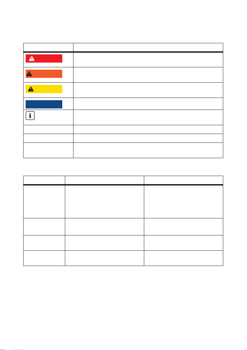
Symbols
Symbol Explanation
Indicates a hazardous situation which, if not avoided, will result in death
or serious injury.
Indicates a hazardous situation which, if not avoided, could result in death
or serious injury.
Indicates a hazardous situation which, if not avoided, could result in minor
or moderate injury.
Indicates a situation that can result in property damage if not avoided.
Indicates information that is important for a specific topic or objective, but
is not safety-relevant.
☐ Indicates a requirement for meeting a specific goal.
☑ Desired result.
✖ Undesired result. Followed by a solution on how to achieve the desired
result.
Typography
Typography Usage Example
"light" • Display messages
• Parameters
• Terminals
•Slots
bold •Elements that are to be selected
• Elements that are to be specified
> • A series of elements that are to
be selected
[Button/key] • Button or key that you are to
select or press
• The inverter switches to the
"Stop" mode.
• Set the "FanTest" parameter to
1.
•Select Plant > Detect.
• Select [Start detection].
Nomenclature
In this manual, the Sunny Central of the HE production series is referred to as a Sunny Central or
inverter.
In this manual, the Sunny Central Communication Controller is also referred to as SC-COM.
10 SCxxxHE-20-BE-BEN111210 Operating Manual
Page 11
SMA Solar Technology AG 2 Safety
2Safety
2.1 Intended Use
The Sunny Central is a central inverter which converts the direct current from PV modules into
alternating current. The maximum permissible DC input voltage of the inverter must not be exceeded.
The Sunny Central is suitable for indoor installation provided that the specified safety distances are
maintained. The enclosure complies with the IP21 degree of protection. IP21 means that the closed
inverter is protected against vertically falling dripping water. The inverter is classified under Class
3 C1L according to EN 60721-3-3.
Inverters of the HE series may only be operated in conjunction with a suitable transformer. The
tr ans for mer must be d esi gne d fo r the vol tag es t hat aris e du rin g pulsed inverter operation. The voltages
can reach a magnitude of maximum ±1 450 V to ground. (see the "Medium-voltage Transformer"
Technical Information at www.SMA.de/en).
Se tti ngs tha t af fect gri d ma nag eme nt m ay not be dis abl ed o r mo dified without first obtaining approval
from the grid operator.
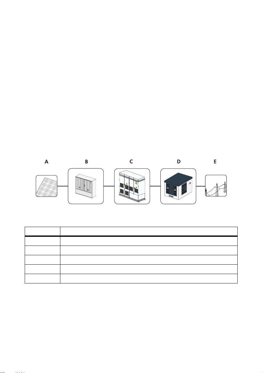
Figure1: Principle of a grid-tie PV plant with an inverter
Position Designation
APV modules
B DC sub-distribution box (e.g. Sunny String-Monitor)
C Sunny Central
D Medium-voltage transformer (e.g. Transformer Compact Station)
E Power distribution grid
Operating Manual SCxxxHE-20-BE-BEN111210 11
Page 12

2 Safety SMA Solar Technology AG
2.2 Safety Instructions
Electrical Risk
Risk of electric shock when touching conductive parts
High voltages that can cause electrical shocks are present in the inverter. Work on the inverter is only
allowed if the power is disconnected and in compliance with the guidelines that apply at the
installation location.
• Disconnect the following components:
– Grid voltage for grid feed-in
– Internal power supply
–DC voltage from the PV array
– Additional external voltages (e.g. control signals of a control room)
• Ensure that the device cannot be reconnected.
•Ensure that no voltage is present.
• Ground and short-circuit.
• Cover any adjacent live components.
Electric shock through capacitors not fully discharged
Hazardous voltages may still be present in the inverter even if the AC and DC main switches are
switched off.
• Wait at least 10 minutes after switching off the inverter.
Electric shock caused by damage to the inverter
Using a damaged inverter can lead to serious or lethal injuries through electric shock.
• Only use the inverter when it is functioning properly and safely.
• Check the inverter regularly for visible damage.
• Ensure that all safety features are freely accessible at all times.
• Regularly check for correct functioning.
Electric shock caused by ground fault
If a ground fault occurs, sections of the plant that appear grounded may in fact be energized.
• Ensure that no voltage is present before touching.
Electric shock when entering the PV field
The insulation monitoring device with GFDI or Remote GFDI does not provide protection from injury
when GFDI is activated. PV modules grounded by means of GFDI disperse voltage to the ground.
When entering the PV field, lethal electric shocks may occur.
• Before entering the PV field, switch the PV modules to insulated operation.
• Ensure that the insulation resistance of the PV field is greater than 1 k Ω .
12 SCxxxHE-20-BE-BEN111210 Operating Manual
Page 13

SMA Solar Technology AG 2 Safety
Electric shock resulting from a failure to comply with safety requirements
Failure to follow this manual, the general instructions or the safety instructions may lead to severe
injury or death from electric shock.
• Only perform work as described in this manual.
• Observe all safety instructions.
• Establish all electrical connections according to the circuit diagram.
• Safely store the documentation within the immediate area of the inverter. It must be accessible
to service and maintenance personnel at all times.
If the key remains in the door lock, the inverter can be opened by unauthorized persons.
• Remove the key from the door locks and from the key switch.
• Keep the keys in a safe place.
Electrostatic discharge can damage electronic components
Electrostatic discharge can damage or destroy electronic component parts.
• When working on the inverter or handling components, observe the ESD safety regulations and
wear protective gloves.
• Discharge the electrostatic charge through contact with unvarnished, grounded enclosure parts
(e.g. the protective conductor connection on the doors). Only then is it safe to touch any
electronic components.
Burn Hazard
Some components, such as fuses, can become hot during operation.
• Wear safety gloves when working on the inverter.
Inverter Damage
Tampering with the device may result in plant damage.
• Do not operate the inverter while the door is open.
Penetrating moisture can damage the inverter.
• Do not open the inverter when it is raining or the humidity is greater than 95%.
Warning signs must be easily readable at all times and must be replaced in the event of damage.
Hazard due to blocked escape route
Opening of the doors of 2 opposing inverters blocks the escape route. An escape route must be
available at all times. Make sure the minimum passage width of the route meets local standards. In
Germany, the minimum passage width is 500 mm.
• Only the door of one inverter may be open at any given time.
Operating Manual SCxxxHE-20-BE-BEN111210 13
Page 14

2 Safety SMA Solar Technology AG
2.3 Qualification of Skilled Worker
All work on the inverter may only be carried out by qualified technical personnel. Qualified means
that the personnel have been properly trained for their assigned tasks.
For commissioning and operating the inverter, the personnel must be familiar with the installation
manual and the user manual. The safety instructions must be observed in particular.
14 SCxxxHE-20-BE-BEN111210 Operating Manual
Page 15
SMA Solar Technology AG 3 Product Description
3 Product Description
3.1 Sunny Central
3.1.1 Design and Function of the Sunny Central
The Sunny Central is a PV inverter that converts the direct current from the PV array into alternating
current for the grid.
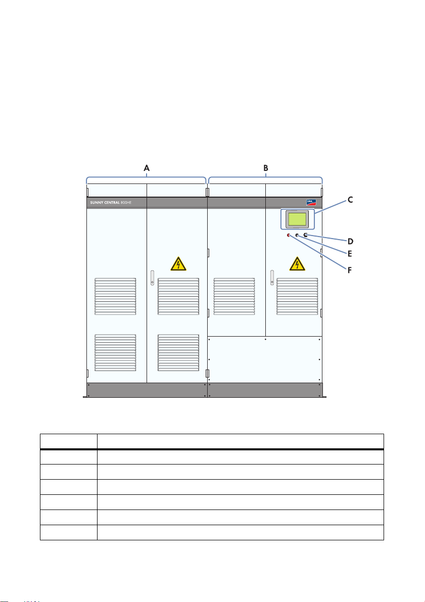
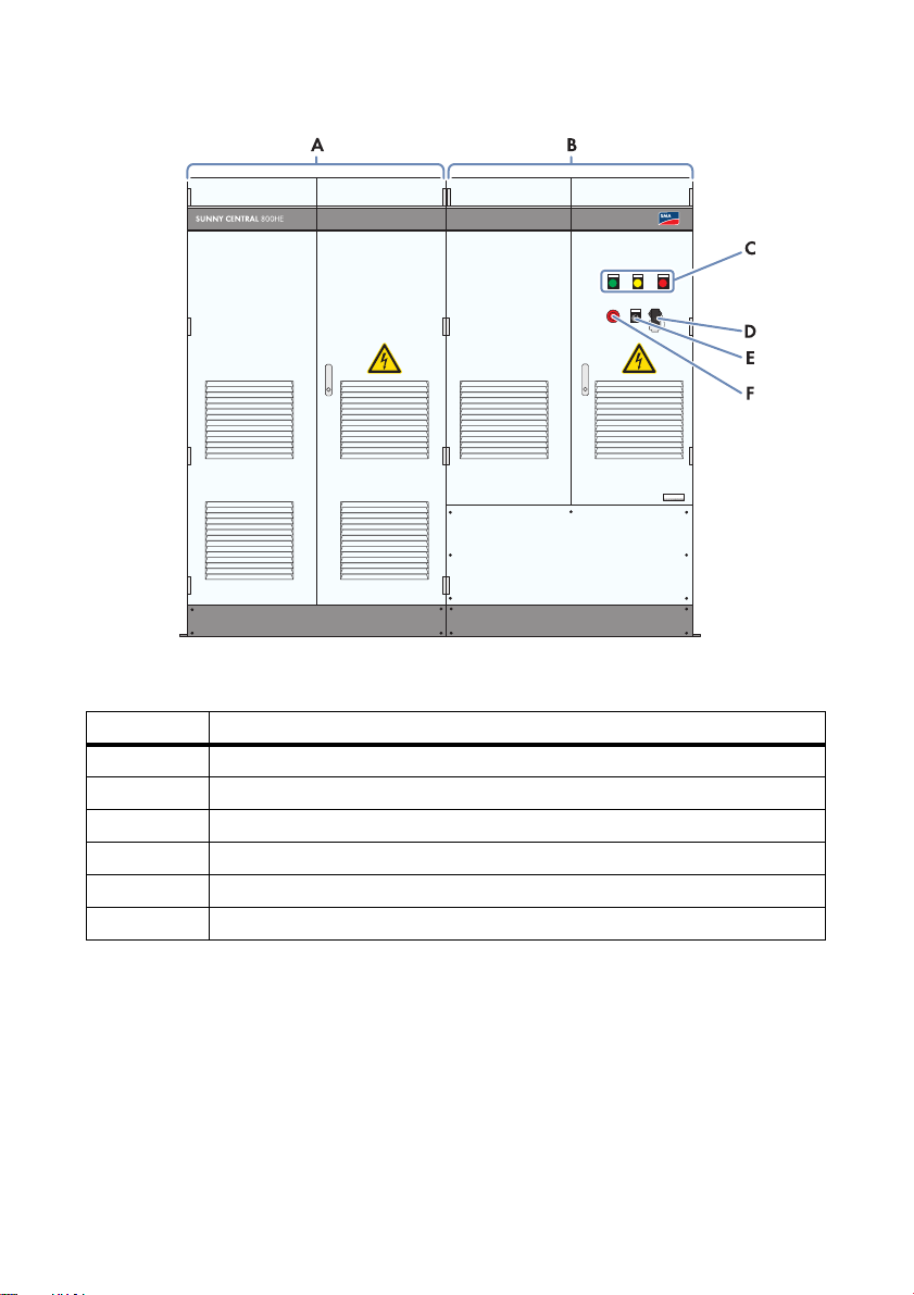
Figure2: Sunny Central, using the example of a Sunny Central 800HE with touch display
Position Description
A Inverter cabinet
B Connection cabinet
CTouch display
D Service interface
EKey switch
FQuick stop
Operating Manual SCxxxHE-20-BE-BEN111210 15
Page 16
3 Product Description SMA Solar Technology AG
Figure3: Control elements of a Sunny Central 800HE with indicator lights
Position Description
A Inverter cabinet
B Connection cabinet
C Indicator lights
D Service interface
EKey switch
FQuick stop
The Sunny Central is controlled via the SC-COM and Power Reducer Box and can therefore meet the
requirements of your grid operator.
When switched on, the inverter will cycle through various operating states:
16 SCxxxHE-20-BE-BEN111210 Operating Manual
Page 17
SMA Solar Technology AG 3 Product Description
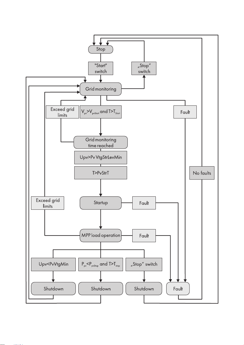
Figure4: Principle overview of the operating states of the Sunny Central
Operating Manual SCxxxHE-20-BE-BEN111210 17
Page 18

3 Product Description SMA Solar Technology AG
Stop
The Sunny Central is switched off. "Stop" or "Remote control disconnection active" appears on the
display.
If the key switch is set to "Start", the Sunny Central switches to the "Grid monitoring" operating state.
Grid monitoring
The Sunny Central is in the "Grid monitoring" operating state. "Wait. valid AC grid" appears on the
display.
The grid limits will now be monitored continuously. If a grid fault does not occur during the grid
monitoring time, the AC contactor closes and the Sunny Central switches to "Grid monitoring time
reached" operating state.
If the grid limits are exceeded during the monitoring time T
grid monitoring
, the Sunny Central will
reactivate "Grid monitoring".
Grid monitoring time reached
The Sunny Central is in the "Grid monitoring time reached" operating state. "Wait. for PV voltage" or
"Warten auf EVU"* appears on the display.
If the input voltage U
exceeds the start voltage "PvVtgStrLevMin", the Sunny Central waits until the
PV
time specified in the "PvStrT" parameter elapses. If the input voltage UPV does not fall below the start
voltage "PvVtgStrLevMin" dur ing thi s ti me, the Sun ny Ce ntr al c hec ks w het her the AC g rid is connected.
If a valid AC grid is available, the Sunny Central switches to the "Startup" operating state.
The start voltage "PvVtgStrLevMin" must be adjusted to conform to the PV array connected to the
Sunny Central. Check and adjust the start voltage as necessary.
Startup
The Sunny Central is in the "Startup" operating state. "Operation" appears on the display.
The Sunny Central moves to its initial operating point and begins the feed-in process.
MPP Load Operation
In the MPP operating state, the Sunny Central feeds power into the grid and operates permanently at
the Maximum Power Point (MPP). "Operation" and the amount of fed-in power appears on the
display.
If the measured power PPV during the time interval T
is less than P
Stop
or the key switch is set to
pvStop
"Stop", the Sunny Central switches to the "Shutdown" operating state.
Shutdown
The Sunny Central is in the "Shutdown" operating state. "Operation" appears on the display.
If the key switch is set to "Stop", the Sunny Central switches to the "Stop" operating state. If the
Su nny Cen tra l sh uts dow n be cau se t he f eed -co ndi tio ns h ave not been met, the Sunny Central switches
to the "Grid monitoring" operating state.
* The inverter is waiting for feed-in authoriziation from the grid operator.
18 SCxxxHE-20-BE-BEN111210 Operating Manual
Page 19

SMA Solar Technology AG 3 Product Description
Fault
If a fault occurs during operation, the Sunny Central switches off and the "Fault" appears on the
display (see section 10"Troubleshooting",page72).
3.1.2 Touch Display
Depending on which option is ordered, the Sunny Central may be equipped with a touch display.
Different kinds of inverter data can be viewed on the touch display. The touch display is only used as
a means for viewing data. The display switches off if it is inactive for more than 5 minutes. It switches
on when it is touched.
3.1.3 Indicator Lights
Depending on which option is ordered, the Sunny Central may be equipped with 3 indicator lights.
The indicator lights show the status of the inverter.
The functions of each status are described below.
Status Designation Function
Green indicator
light glows
continuously
Yellow and green
indicator lights
glow
continuously
Yellow indicator
light glows
continuously
Red indicator
light glows
continuously
All indicator lights
are off
Feed-in operation The Sunny Central is feeding
into the power distribution grid.
Limited operation The Sunny Central has detected
a warning. The warning
currently does not affect the
operation of the Sunny Central.
Warning The Sunny Central is currently
not feeding power into the grid
an d ha s detec ted a warnin g. I t is
automatically reset as soon as
the warning is no longer present.
This status is used, for instance,
when the level of irradiation is
low.
Fault
No feed-in
operation
The Sunny Central has detected a
fault and is now switched off
(see section
10"Troubleshooting",page72).
The Sunny Central is not feeding
into the grid, the supply voltage
is disconnected, or the key
switch is set to "Stop".
Operating Manual SCxxxHE-20-BE-BEN111210 19
Page 20

3 Product Description SMA Solar Technology AG
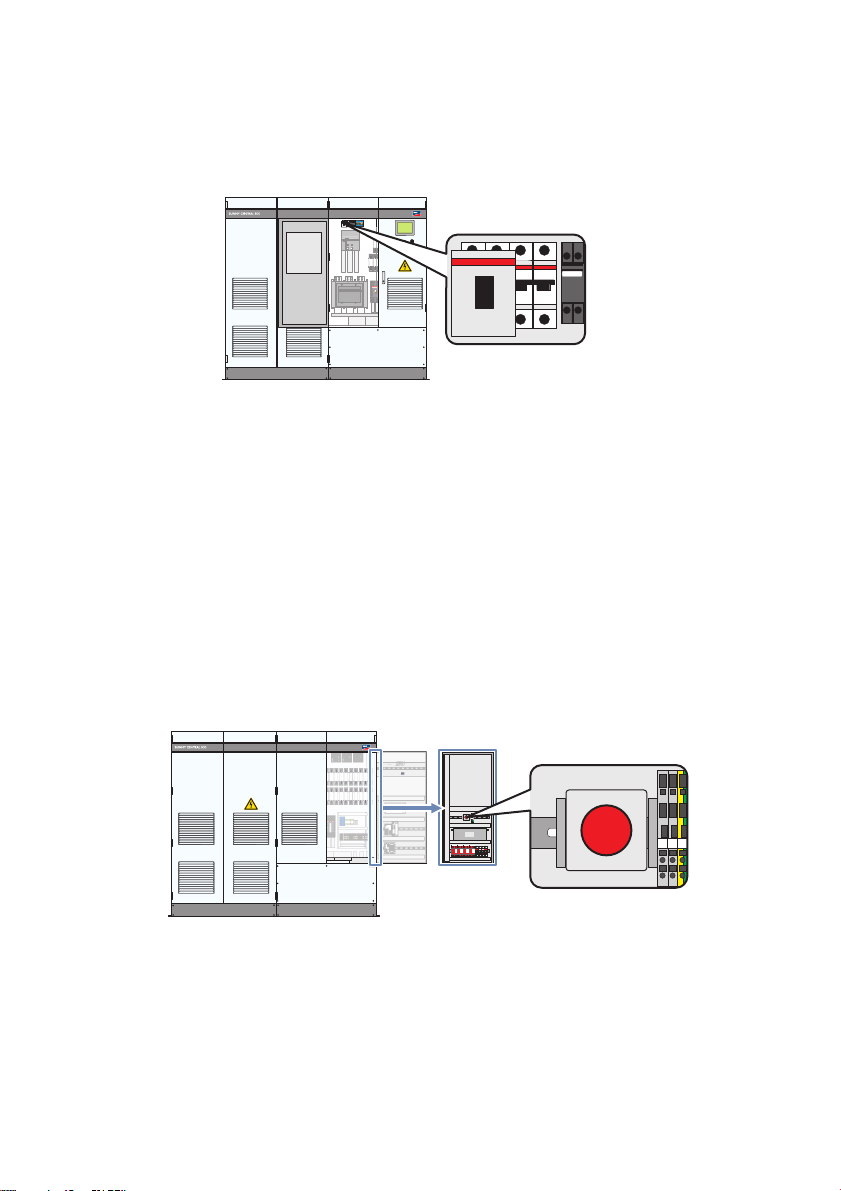
3.1.4 Quick stop
In case of emergency, this switch enables disconnection of the inverter from the PV array and the
medium-voltage grid within 500 ms.
Tripping the quick-stop function
The quick-stop function may only be tripped if there is imminent danger.
Pressing the quick-stop button does not trigger a quick discharge of the capacitors.
Pressing the quick-stop button opens the DC contactor, switches off the inverter bridge and
disconnects the inverter from the AC grid.
3.1.5 Key switch
The key switch is used to switch the Sunny Central on and off.
Switch position "Start"
After turning the switch to the "Start" position, the Sunny Central switches from "Stop" to
"Grid monitoring" operating state and the DC main switch is turned on. If there is sufficient irradiation
and a valid grid connection, the Sunny Central switches to feed-in operation. If there is insufficient
irradiation, the input voltage is too low for startup and the Sunny Central remains in the
"Grid monitoring" state.
Switch position "Stop"
If the key switch is turned to "Stop" while the Sunny Central is in the "Grid monitoring" state, a motor
drive automatically shuts off the DC main switch. The Sunny Central switches to the "Stop" operating
state.
If the key switch is turned to "Stop" while the Sunny Central is in "MPP load operation" state, the
Sunny Central switches to the "Shutdown" operating state. Once shutdown is complete, the AC
contactor and the DC main switch tur n off aut oma tic all y and the Sunny C entral goe s into "Stop" mode.
20 SCxxxHE-20-BE-BEN111210 Operating Manual
Page 21
SMA Solar Technology AG 3 Product Description
HE
SUNNY CENTRAL
STRING MONITOR CONTROLLER
3.2 Sunny Central Communication Controller
The SC-COM is the central communication interface of the inverter. The SC-COM establishes the
connection between the inverter and the plant operator.
Figure5: SC-COM
The SC-COM collects all data from the connected devices. The SC-COM enables monitoring,
parameterization and remote diagnosis of the inverter via computer, as well as power regulation by
the grid operator.
These various tasks performed by the SC-COM can be organized in 2 separate networks:
• Monitoring network: for performing monitoring, parameterization and remote diagnosis.
• Regulation network: for transmitting the grid management specifications of the grid operator.
Since the regulation network is used exclusively for transmitting data from the grid operator, the
specifications will be available in the required time.
If the amount of data flowing through the monitoring network is low, the grid operator specifications
can also be transmitted via the monitoring network. In this case, there is no need for 2 networks.
The operator can access all data stored in the SC-COM via an Ethernet connection.
You can set the parameters of the inverter via the SC-COM.
The networks can be set up using copper cables or optical fibers.
PV plant communication type
The interfaces of the SC-COM are set by default to "COM3" and a 115 200 baud rate. Do
not modify these settings.
3.3 Sunny Central String-Monitor Controller
Depending on which options are ordered, the Sunny Central may be equipped with a
Sunny Central String-Monitor Controller for string monitoring. This controller allows communication
between the Sunny String-Monitors and the Sunny Central.
Operating Manual SCxxxHE-20-BE-BEN111210 21
Page 22
3 Product Description SMA Solar Technology AG
HE
SUNNY CENTRAL
STRING MONITOR CONTROLLER
SUNNY CENTRAL
STRING MONITOR CONTROLLER
Figure6: Sunny Central String-Monitor Controller
The String-Monitor units measure the string currents via the integrated measuring circuit board and
continuously calculate the average value of the string currents. The measuring circuit board compares
the string currents with the average values. If a string current exceeds or falls short of the specified
threshold for the average value, a warning or fault is generated and displayed via the indicator lights
or the display and on the SC-COM surface.
3.4 Remote shutdown
With the remote shutdown unit, you can set the Sunny Central to switch off or shut down within
6 seconds (e.g. from a control room). The remote shutdown is similar to the stop function of the key
switch.
If the remote shutdown unit is activated from the control room when the Sunny Central is in
"Grid monitoring" operating state, a motor drive automatically shuts off the main DC switch and the
Sunny Central switches to "Stop".
If the remote shutdown unit is activated from the control room when the Sunny Central is in the
"MPP load operation" operating state, the Sunny Central switches to "Shutdown". Once shutdown is
co mpl ete , th e AC con tactor a nd t he D C ma in s wit ch t urn off aut oma tic all y an d the Sun ny C ent ral goe s
into "Stop" operating state.
3.5 Insulation Monitoring
3.5.1 How Insulation Monitoring Works
Insulation monitoring is a mechanism for ensuring plant protection in electrical devices. There are
different types of insulation monitoring:
• In grounded grids
Insulation monitoring is performed via a residual current monitoring device. If an insulation
failure occurs, the fault currents will be detected and interrupted.
• In ungrounded grids
An insulation monitoring device constantly determines the insulation resistance using an active
measurement procedure. If the insulation resistance falls below the warning threshold specified
in the insulation monitoring device, an insulation warning will given via the indicator lights or on
22 SCxxxHE-20-BE-BEN111210 Operating Manual
Page 23

SMA Solar Technology AG 3 Product Description
ono
n
o
o
f
f
off
INFO
TEST
RESET
MENU
U2-F10
HE
the display. This allows measures to be taken to prevent errors (e.g. injury risk due to leakage
current or plant failure). If the insulation resistance falls below the specified warning threshold,
then the plant can switch itself off. The "IsoErrIgn" parameter can be used to configure the
shutdown process when an error occurs.
3.5.2 GFDI
Depending on the order, ground fault monitoring in the Sunny Central is carried out via ground fault
detection interruption (GFDI). This process is used to ground one pole of the PV array.
GFDI is performed via a high-performance k-type miniature circuit breaker with adjustable operating
current. It is integrated in the inverter and connected between an input busbar and the protective
conductor bar.
Figure7: GFDI in the Sunny Central
Ground fault on ungrounded pole
If a ground fault occurs at the PV array pole that is not grounded, a fault current will flow to the
grounded pole through the GFDI thus triggering it. The fault current is interrupted as a result and the
PV array is not grounded via the ground fault.
If the GFDI is tripped, the insulation monitoring device switches off the inverter so that the insulation
error can be corrected.
Ground fault on grounded pole
The GFDI is bypassed when a ground fault occurs in the grounded pole of the PV array. The ground
fault on the grounded pole cannot be reliably detected. A ground fault that occurs unnoticed on the
grounded pole poses a safety risk. An additional ground fault on the non-grounded pole leads to
higher fault currents that cannot be interrupted by the GFDI. We therefore recommend using an
additional insulation monitoring device in grounded systems. This will allow the insulation to be
checked at regular intervals.
3.5.3 Remote GFDI
Depending on the order, ground fault monitoring in the Sunny Central is carried out via ground fault
detection interruption with motor drive, abbreviated remote GFDI. This process is used to ground one
pole of the PV array. Remote GFDI also enables automatic error processing. This prevents downtimes
and service calls due to temporary insulation errors such as condensation on the PV modules.
Operating Manual SCxxxHE-20-BE-BEN111210 23
Page 24
3 Product Description SMA Solar Technology AG
ono
n
o
o
f
f
off
INFOTEST
RESET
MENU
U2-F10
HE
SUNNY WEBBOX
U
S
B
C
O
M
N
E
T
C
O
M
S
M
A
C
O
M
M
E
M
O
R
Y
R
E
P
O
R
T
S
Y
S
T
E
M
P
O
W
E
R
SUNNY CENTRAL
STRING MONITOR CONTROLLER
onon
o
offoff
INFO
TEST
RESET
MENU
U2-F10
HE
GFDI is performed via a high-performance k-type miniature circuit breaker with adjustable operating
current. It is integrated in the inverter and connected between an input busbar and the protective
conductor bar.
Figure8: Remote GFDI in the Sunny Central
If the remote GFDI trips, a temporary error is assumed and a motor will close the GFDI after a delay.
The triggered remote GFDI can be closed without an external starting command. The inverter can
switch back to feed-in operation after a delay.
In the default setting, the Sunny Central software will attempt to start the GFDI up to 3 times per day.
If the GFDI is triggered on consecutive days, the software assumes a permanent insulation error and
shuts down the inverter permanently. In this case an electrically qualified person needs to check and,
if necessary, repair the insulation and then confirm the error.
3.5.4 Soft Grounding
Depending on the order, the Sunny Central can also monitor for ground faults via soft grounding. This
process grounds one pole of the PV array through a resistor.
Figure9: Soft grounding in Sunny Central
If a ground fault occurs on the non-grounded pole of the PV array, the soft grounding resistance will
generate a fault current. The fault current increases the voltage of the grounded pole in relation to the
protective conductor. With soft grounding, the insulation is monitored by measuring the voltage
between the grounded pole and the protective conductor. "U
determine the DC voltage when the grounded pole is positive or negative, respectively.
24 SCxxxHE-20-BE-BEN111210 Operating Manual
+ to PE" or "UPV‒ to PE" is used to
PV
Page 25

SMA Solar Technology AG 3 Product Description
If the amount of voltage measured exceeds a certain threshold, the grounding of the PV array is
disconnected and the fault current is interrupted. This threshold can be set as a parameter.
If a soft grounding fault occurs, the inverter will stop operating. An electrically qualified person is
required to check and repair the insulation if necessary and reactiv ate the d evi ce b y pr ess ing t he r ese t
button.
It is not possible to detect an insulation error on the grounded pole.
3.5.5 Insulation Monitoring Device
Depending on the order, an insulation monitoring device monitors the insulation resistance of the
PV plant in ungrounded networks.
In the "MPP load operation" operating state, the insulation resistance of the entire system will be
detected, from the PV modules to the medium-voltage transformer.
If the inverter is the "Grid monitoring" operating state, only the insulation resistance from the
PV modules to the inverter will be detected.
Figure10: Insulation monitoring device in Sunny Central
Object Description
ADisplay
BLEDs
C Control buttons
A measuring circuit and a relay with a changeover contact are integrated in the insulation monitoring
device.
The insulation monitoring device is connected between the PV voltage and the protective conductor.
The contacts of the relay are placed on the customer's terminal strip and can be used by the customer
to trigger an signal light or horn. The specifications of the relay are indicated in the circuit diagram.
If the insulation resistance falls below the specified warning threshold ALARM2, the measuring circuit
closes and LED 2 on the insulation measuring device glows. An insulation warning is generated. In
parallel, the insulation monitoring device activates a relay that includes a changeover contact. This
relay is integrated in the inverter.
Operating Manual SCxxxHE-20-BE-BEN111210 25
Page 26

3 Product Description SMA Solar Technology AG
If an i nsu lat ion erro r oc cur s, t he i nsu lat ion res ista nce wil l fall below the ALARM1 threshold. In this case
the operating behavior of the inverter can be set via parameters:
• If the parameter "IsoErrIgn" is set to Off, the measuring circuit generates a fault message and
the inverter switches off when the ALARM1 value falls below a specific threshold. LED1 turns on.
• If the parameter "IsoErrIgn" is set to On, the error message from the measuring circuit is ignored
when the ALARM1 value falls below a specific threshold. The inverter continues to feed power
into the grid and generates the error message "3504 ‒ insulation failure ignored".
Type of insulation monitoring device used
The insulation monitoring device used is the A-ISOMETER iso-PV device supplied by
Bender GmbH & Co. KG.
3.5.6 GFDI and Insulation Monitoring
If "GF DI a nd I nsu lat ion Mon ito rin g" i s or der ed, you can tem por ari ly d isa ble the gro und ing con nec tio n
of the PV array and check the insulation with the integrated insulation monitoring device.
When t he GFDI is close d, the PV fi eld is grounded and t he insulation resistance cannot be determined.
If the GFDI is open, the grounding connection is disabled and the insulation monitoring device can
continuously measure the insulation resistance. In the "MPP load operation" operating state, the
insulation resistance of the entire system will be detected, from the PV modules to the medium-voltage
transformer. If the inverter is the "Grid monitoring" operating state, only the insulation resistance from
the PV modules to the inverter will be detected.
Insulation monitoring should be performed in the "MPP load operation" operating state so that all
sections of the PV plant are included in the insulation measurement.
The parameter for insulation monitoring allows you to configure how an error message in the
insulation monitoring device will affect the operating behavior of the Sunny Central:
• If the parameter "IsoErrIgn" is set to Off, the measuring circuit generates a fault message and
the inverter switches off when the ALARM1 value falls below a specific threshold. LED1 turns on.
• If the parameter "IsoErrIgn" is set to On, the error message from the measuring circuit is ignored
when the ALARM1 value falls below a specific threshold. The inverter continues to feed power
into the grid and generates the error message "3504 ‒ insulation failure ignored".
Insulation Monitoring
The insulation monitoring device will start measuring once the GFDI is open. The device will initially
assume that the insulation is poor. If the parameter "IsoErrIgn" is set to Off, the inverter will switch off
temporarily.
Within 5 minutes the insulation monitoring device will determine the correct insulation resistance,
which can be viewed on the device's display. If the insulation is intact, the inverter switches back to
"MPP load operation". The error "3505 ‒ ground fault ignored" appears. This error indicates that the
PV array is operating without a grounding connection. If the insulation monitoring process is complete,
the GFDI should close again and thus allow the PV array to operate with a grounding connection.
26 SCxxxHE-20-BE-BEN111210 Operating Manual
Page 27

SMA Solar Technology AG 3 Product Description
If, after approx. 5 minutes, one of the failures "3501 ‒ insulation failure", "3504 ‒ insulation failure
ignored" or "3601 ‒ Warning insulation failure" is displayed, the insulation is defective. In this case,
an electrically qualified person must check and, if necessary, repair the insulation and confirm the
failure.
3.5.7 Remote GFDI and Insulation Monitoring
The "Remote GFDI and Insulation Monitoring" order option enables automatic error correction and
allows you to temporarily disable the grounding connection of the PV array and then check the
insulation with the integrated insulation monitoring device.
Wh en t he G FDI is c los ed, the PV field is g rou nde d an d th e in sul ation resistance cannot be determined.
If the remote GFDI trips, a temporary error is assumed and a motor will close the GFDI after a delay.
The triggered remote GFDI can be closed without an external starting command. The inverter can
switch back to feed-in operation after a delay.
In the default setting, the Sunny Central software will attempt to start the GFDI up to 3 times per day.
If the GFDI is triggered on consecutive days, the software assumes a permanent insulation error and
shuts down the inverter permanently. In this case an electrically qualified person needs to check and,
if necessary, repair the insulation and then confirm the error.
If the remote GFDI is open, the grounding connection is disabled and the insulation monitoring device
can continuously measure the insulation resistance. In the "MPP load operation" operating state, the
insulation resistance of the entire system will be detected, from the PV modules to the medium-voltage
transformer. If the inverter is the "Grid monitoring" operating state, only the insulation resistance from
the PV modules to the inverter will be detected.
Insulation monitoring should be performed in the "MPP load operation" operating state so that all
sections of the PV plant are included in the insulation measurement.
The parameter for insulation monitoring allows you to configure how an error message in the
insulation monitoring device will affect the operating behavior of the Sunny Central:
• If the parameter "IsoErrIgn" is set to Off, the measuring circuit generates a fault message and
the inverter switches off when the ALARM1 value falls below a specific threshold. LED1 turns on.
• If the parameter "IsoErrIgn" is set to On, the error message from the measuring circuit is ignored
when the ALARM1 value falls below a specific threshold. The inverter continues to feed power
into the grid and generates the error message "3504 ‒ insulation failure ignored".
Insulation Monitoring
To disable the grounding connection of the PV array, the "RemMntSvc" parameter must be set to On.
This allows a motor to open the remote GFDI.
If the remote GFDI is opened via the "RemMntSvc" parameter, the insulation monitoring device will
start measuring after the delay defined by the "IsoMeasDly" parameter. This allows the insulation
monitoring device to determine the insulation resistance without interrupting the feed-in operation. If
an insulation failure occurs, it will be considered at the end of the delay.
Operating Manual SCxxxHE-20-BE-BEN111210 27
Page 28
3 Product Description SMA Solar Technology AG
If the insulation is intact, the error "3505 ‒ ground fault ignored" appears. This error indicates that the
PV array is operating without a grounding connection. If the insulation monitoring process is complete,
the "RemMntSvc" parameter should be set to Off and thus allows the PV array to operate with a
grounding connection.
If, after approx. 5 minutes, one of the failures "3501 ‒ insulation failure", "3504 ‒ insulation failure
ignored" or "3601 ‒ Warning insulation failure" is displayed, the insulation is defective. In this case,
an electrically qualified person must check and, if necessary, repair the insulation and confirm the
failure.
3.6 Grid Management
3.6.1 Requirements
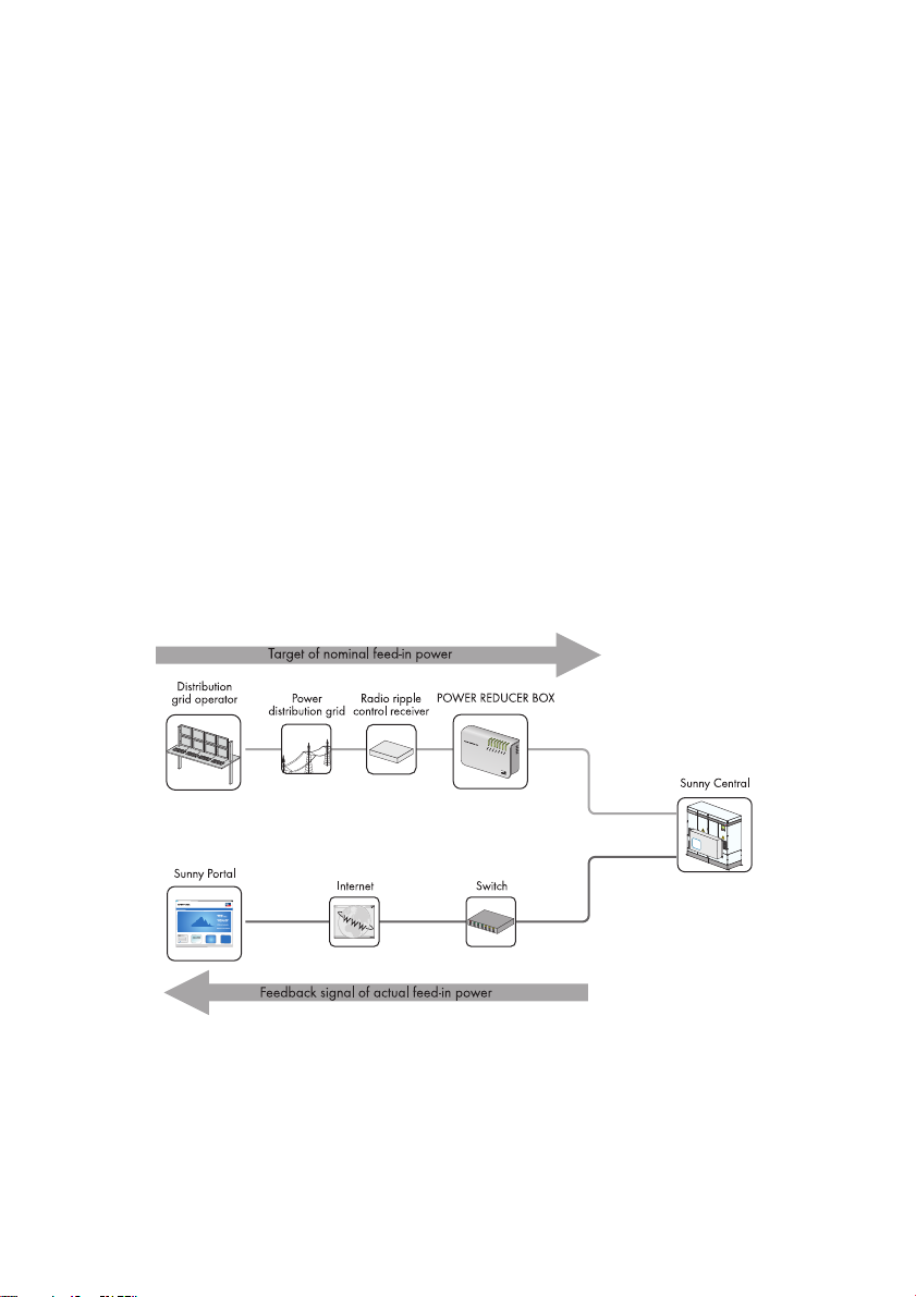
In Germany, PV plants with more than 100 kWp of connected power must be integrated into a feedin and grid management system. First and foremost, the grid operator must be able to limit the power
of the PV plant by remote control and temporarily reduce it to zero in critical cases. The relevant
control commands of the grid operator must therefore be transmitted to the Sunny Central quickly and
reliably for implementation.
The following illustration shows how the specifications of the grid operator are implemented. The
Power Reducer Box sends the specifications of the grid operator to the inverters.
Figure11: Principle of grid integration
Besides the Power Reducer Box, there are two other options for meeting the requirement of grid
management:
• Receiving the signals via 2 analog inputs on the Sunny Central
• Manually adjusting the specifications via parameters
28 SCxxxHE-20-BE-BEN111210 Operating Manual
Page 29

SMA Solar Technology AG 3 Product Description
3.6.2 Active Power Limitation
Five methods are available for limiting the active power regardless of power frequency. The limit can
be defined using a parameter and supplied by the grid operator via an external signal.
In addition to these methods, the active power can also be limited according to the power frequency.
3.6.3 Reactive Power Setpoint
The Sunny Central can provide reactive power. There are 11 methods for specifying the reactive
power setpoint. They include entering a fixed parameter, processing an external signal from the grid
operator or specifying the reactive power using characteristic curve parameters.
3.6.4 Dynamic Grid Support (FRT)
The Sunny Central can support the grid during a grid voltage drop by supplying reactive power.
3.6.5 Decoupling Protection Ramp
After a grid fault, the Sunny Central restarts at a maximum 10% of nominal power per minute using
a decoupling protection ramp. You have the option of switching this decoupling protection ramp on
or off.
If you switch the decoupling protection ramp off, the Sunny Central quickly returns to maximum
power.
If you wish to deactivate the decoupling protection ramp, consult the SMA Service Line.
3.6.6 Grid Management Shutdown
If the power grid becomes unstable and overloaded, grid management requires that the inverter
disconnect from the grid immediately. In such cases the relevant signal will be sent by the grid
operator or the transfer point safety system. The inverter disconnects from the grid immediately and
displays error 9013.
The error will be reset in the inverter after a signal is sent by the grid operator of transfer point safety
system.
3.7 Active Islanding Detection
The active islanding detection function detects the formation of island grids during a grid failure and
disconnects the Sunny Central from the grid.
Stand-alone grids form when the following conditions are present at the same time:
• The medium voltage grid fails
• The Sunny Central feeds in x amount of power
• There is a consumer on the same branch of the grid with a load equal to x amount of power
To enable the active islanding detection, contact the SMA Service Line.
Operating Manual SCxxxHE-20-BE-BEN111210 29
Page 30
3 Product Description SMA Solar Technology AG
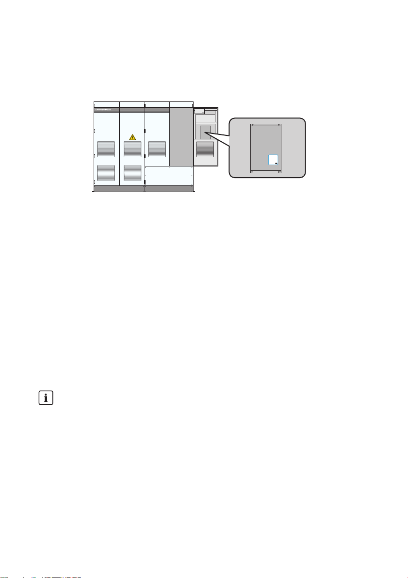
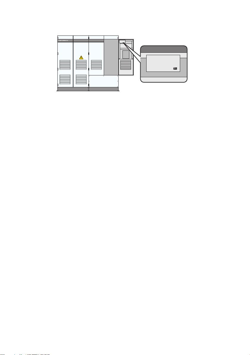
3.8 Serial Number and Device Type
The serial number (Serial No.) and device type (Type) of the Sunny Central are listed on the type
label. The type label is located on the inside of the right door on both the inverter cabinet and the
connection cabinet.
The serial number and the type of product, as well as device-specific characteristics are specified on
both type labels.
The serial number can also be found on the Sunny Central on the top left corner of the roof.
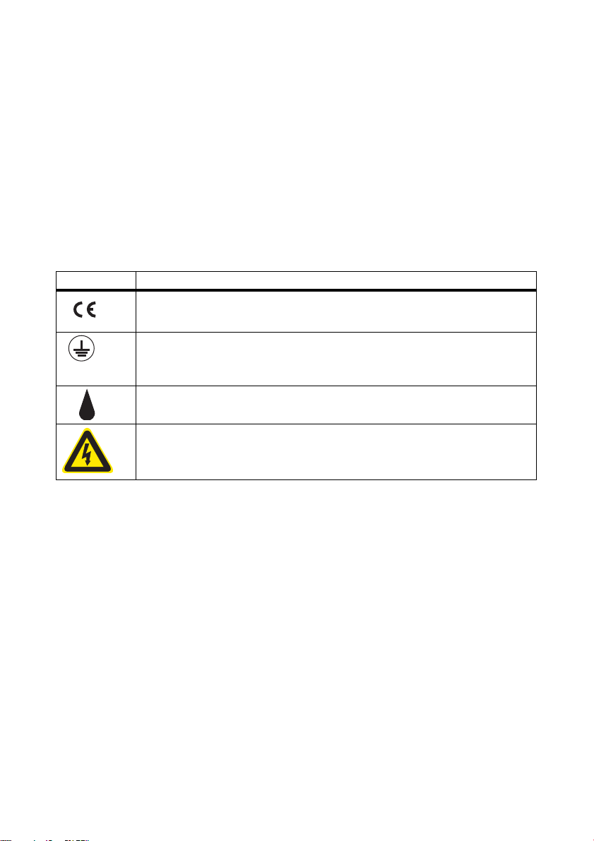
3.9 Symbols on the Sunny Central
All the symbols on the Sunny Central and the type label are explained below.
Symbol Designation
CE mark.
The Sunny Central complies with all relevant EU directives.
Protection class I.
All operating facilities are connected to the protective conductor system of the
Sunny Central.
Degree of protection IP21.
The Sunny Central is protected against dripping water.
Beware of dangerous electrical voltage.
The Sunny Central operates at high voltages. All installation work on the
Sunny Central must be performed by electrically qualified persons only.
30 SCxxxHE-20-BE-BEN111210 Operating Manual
Page 31

SMA Solar Technology AG 4 Setting Network
4 Setting Network
Before you can connect the inverter to a computer via the service interface or the Internet, the
SC -CO M mu st be set up in the plan t ne two rk. To al low mul tip le Sunny Centrals operating on the same
network, the SC-COM of each Sunny Central must be assigned a unique network address.
Figure12: Example of a system network of 2 inverters with indicator lights
Operating Manual SCxxxHE-20-BE-BEN111210 31
Page 32

4 Setting Network SMA Solar Technology AG
Figure13: Basic structure of large-scale plant networks
Procedure:
• Set the IP Address on the Laptop
• Set the IP address of the inverter
Setting the IP Address on the Laptop
If you are working with a DHCP-enabled laptop, it will automatically be assigned an IP address by
the network server.
If your laptop is not DHCP-enabled, you will need to manually enter the IP address.
1. Select Start > Run in Windows.
2. Enter ncpa.cpl in the box and press [OK].
☑The "Network Connections" window opens.
3. Double-click the LAN connection via which the SC-COM is connected.
32 SCxxxHE-20-BE-BEN111210 Operating Manual
Page 33

SMA Solar Technology AG 4 Setting Network
4. Select [Properties].
☑The "Local Area Connection Properties" window opens.
5. Select "Internet protocol (TCP/IP)" and click [Properties].
☑ The "Internet Protocol (TCP/IP) Properties" window opens.
6. Note down the existing network settings so that you can restore the settings in your computer
after starting the Sunny Central.
7. Enter the following values and press [OK].
– IP address: 10.100.100.1
– Subnet mask: 255.0.0.0
8. In the "LAN Connection Properties" window, select [OK]. The settings are now applied.
9. In the "Network Connections" window, select [OK]. This causes the window to close.
☑ The computer is set according to the network settings of the Sunny Central.
Setting the IP address of the Inverter
1. Connect the laptop to the service interface of the Sunny Central using a network cable.
2. Open a web browser such as Windows Explorer.
3. Type 192.168.100.2 in the address bar of the web browser.
☑ The SC-COM interface appears.
4. Enter the installer password in the appropriate field on the homepage and press [Login].
5. Select Sunny Central > Settings > Network.
6. Enter the following values based on the structure of the monitoring network and the regulation
network:
–"IP Address:"
–"Subnet mask"
–"Gateway"
7. Complete the process by pressing [Save] and [Confirm].
Operating Manual SCxxxHE-20-BE-BEN111210 33
Page 34

5 SC-COM Communication SMA Solar Technology AG
5 SC-COM Communication
5.1 Displaying Spot Values
The SC-COM operating manual contains a detailed description of the SC-COM interface.
1. Access the SC-COM interface.
2. Enter the installer password in the appropriate field on the homepage and press [Login].
3. Select Data > Devices.
4. Select .
☑ A list of existing device types appears.
5. Select the desired device type.
☑ A list appears containing all existing devices of this type.
6. Select the desired device.
7. Select the "Spot values" tab.
5.2 Changing Parameters
Parameters are changed via the SC-COM. You can access the SC-COM either on site via a laptop
or remotely via a PC.
1. Access the SC-COM interface.
2. Enter the installer password in the appropriate field on the homepage and press [Login].
3. Select Plant > Devices.
4. Select .
☑ A list of existing device types appears.
5. Select the desired device type.
☑ A list appears containing all existing devices of this type.
6. Select the desired device from the list.
7. Select the "Parameters" tab.
8. Change the desired parameter.
9. Confirm parameter by pressing [Save].
34 SCxxxHE-20-BE-BEN111210 Operating Manual
Page 35

SMA Solar Technology AG 5 SC-COM Communication
5.3 Setting Up the Sunny Central String-Monitor Controller
5.3.1 Setting the Parameters for String Current Monitoring in the PV Plant
To configure string current monitoring in your PV plant, the following steps must be performed in order:
• Detect the Sunny Central String-Monitor Controller and the Sunny Central
• Set the Date and Time
• Detect Sunny String-Monitors via the Sunny Central String-Monitor Controller
• Redetect Sunny String-Monitors via the Sunny Central String-Monitor Controller
• Detect the String-Monitors via SC-COM
• Change how Sunny String-Monitors are identified
Detecting the Sunny Central String-Monitor Controller and the Sunny Central
1. Access the SC-COM interface.
2. Enter the installer password in the appropriate field on the homepage and press [Login].
3. Locate the Sunny Central and the Sunny Central String-Monitor Controller:
–Select Data > Detect.
– In the "Total number of devices to be detected" field, enter 2.
–Select [Start detection].
☑ The SC-COM starts detecting all devices and displays its progress. Once all devices have
been detected, the SC-COM displays "### Device detection finished ###".
☑ The devices are detected.
Setting the Date and Time
1. Select Data > Devices.
2. Select .
☑ A list of existing device types appears.
3. Select Sunny Central String-Monitor Controller.
4. Select the "Spot values" tab.
5. Make sure the date "SysDt" and time "SysTm" of the Su nny Ce ntral Stri ng-Monito r Controll er are
correct.
6. If the settings are incorrect, change the "Dt" and "Tm" parameters (see section 5.2"Changing
Parameters",page34).
Operating Manual SCxxxHE-20-BE-BEN111210 35
Page 36

5 SC-COM Communication SMA Solar Technology AG
Detecting Sunny String-Monitors via the Sunny Central String-Monitor Controller
Detecting the Sunny String-Monitors can take several minutes.
It may take several minutes to detect the Sunny String-Monitors depending on the number of
devices and how far apart they are.
1. Select the "Parameters" tab.
2. Set parameter "DevFunc" to "AutoDetect_SSMU".
3. Confirm entry with [Save].
4. Select the "Spot values" tab
5. Select "SSMUNoOf" and check the number of detected Sunny String-Monitors. If all
Sunny String-Monitors have been detected, use the SC -COM to detect them again. If only some
of the Sunny String-Monitors have been detected, use the Sunny Central String-Monitor
Controller to detect them again.
Redetecting Sunny String-Monitors via the Sunny Central String-Monitor Controller
1. Select the "Parameters" tab.
2. Set parameter "DevFunc" to "DetectSSMURetry".
3. Confirm entry with [Save].
4. Select the "Spot values" tab
5. Select "SSMUNoOf" and check the number of detected Sunny String-Monitors. If all
Sunny String-Monitors have been detected, use the SC -COM to detect them again. If only some
of the Sunny String-Monitors have been detected, contact the SMA Service Line.
Using the SC-COM to Detect Sunny String-Monitors
1. Select Data > Detect.
2. In the "Total number of devices to be detected" field, enter the number of
Sunny String-Monitors +2.
3. Select [Start detection].
☑ The SC-COM starts detecting all devices and displays its progress. Once all devices have
been detected, the SC-COM displays "### Device detection finished ###".
☑ The Sunny String-Monitors are detected.
36 SCxxxHE-20-BE-BEN111210 Operating Manual
Page 37

SMA Solar Technology AG 5 SC-COM Communication
Changing How Sunny String-Monitors are Identified
1. Select the first Sunny String-Monitor from the list of devices.
2. Select the "Parameters" tab.
3. Select the parameter "SSM Identifier" and allocate a unique identification number to the
Sunny String-Monitor. Note down the identification number.
4. Change how the remaining Sunny String-Monitors are identified using the same process.
5.4 Optional Settings for PV Plant Monitoring
5.4.1 Changing the Communication Period
The communication period is the time during which the Sunny Central String-Monitor Controller
communicates with the Sunny String-Monitors. The communication period is set to 10:00 a.m. to
3:00 p.m. by default.
1. Select the parameter "MoniTmComOn" and specify the start of the monitoring period (see
section 5.2"Changing Parameters",page34).
2. Select the parameter "MoniTmComOff" and specify the end of the monitoring period.
3. Confirm entry with [Save].
5.4.2 Changing the Monitoring Period
The monitoring period refers to the time in which the PV plant is being monitored by the
Sunny String-Monitors. The monitoring period is set to 10:00 a.m. to 3:00 p.m. by default.
You can set the monitoring period for all the Sunny String-Monitors or allocate a separate monitoring
period to each group of Sunny String-Monitors.
The monitoring period must lie within the communication period.
Setting the Monitoring Period of all Sunny String-Monitors
1. Select the parameter "MoniTmGrAllOn" and specify the start of the monitoring period
(see section 5.2"Changing Parameters",page34).
2. Select the parameter "MoniTmGrAllOff" and specify the end of the monitoring period.
3. Confirm entry with [Save].
Setting the Monitoring Period for Individual Groups of Sunny String-Monitors
1. Select the parameter "MoniTmGr1On" and specify the start of the monitoring period
(see section 5.2"Changing Parameters",page34).
2. Select the parameter "MoniTmGr1Off" and specify the end of the monitoring period.
3. Confirm entry with [Save].
4. Repeat steps 1, 2 and 3 for the other groups.
Operating Manual SCxxxHE-20-BE-BEN111210 37
Page 38

5 SC-COM Communication SMA Solar Technology AG
5.4.3 Assigning PV Strings to Various Measuring Channels
You can assign the strings to the 8 measuring channels in order to simplify monitoring.
The number of strings per channel for the eight measuring channels can be selected from 1 to 4. The
default setting is "1".
With the parameter "No.of Strings" you can assign all the measuring channels of the
Sunny String-Monitor to a string number of 1 to 4. This avoids having to set the number of strings for
each of the individual channels, since this is automatically set for the grouped channels.
1. Select a Sunny String-Monitor from the list of devices.
2. Select the "Parameters" tab.
3. In parameter fields "No.of Strings 1" to "No.of Strings 8" enter the number of PV strings per
measuring channel or in the field "No.of Strings" the number of PV strings for all the measuring
channels.
4. Confirm entry with [Save].
5.4.4 Assigning PV strings to Different Groups
PV string data is monitored continuously and analyzed in terms of groups so that potential errors can
be detected immediately. It is hence advisable to split the PV strings into various groups if some strings
are shaded, aligned differently or equipped with different modules.
All PV strings are placed in Group 1 by default.
Group 0 is not monitored. Group 0 is not monitored, which means only PV strings excluded from
monitoring should be assigned to this group.
1. Select a Sunny String-Monitor from the list of devices.
2. Select the "Parameters" tab.
3. Select the parameters "Group String 1" to "Group String 8" and assign them to a group
(see section 5.2"Changing Parameters",page34). Each group must include at least
4 measuring channels.
4. Confirm entry with [Save].
5.4.5 Setting the Tripping Time
You can use the tripping time to set the sensitivity of the string current monitoring given that the tripping
time is included in the calculation of the error sum. The tripping time is set to 180 minutes as default.
1. Select a Sunny Central String-Monitor Controller from the device list.
2. Select the "Parameters" tab.
3. In the parameter field "SMU_T_Ausl." enter the tripping time in minutes.
4. Confirm entry with [Save].
38 SCxxxHE-20-BE-BEN111210 Operating Manual
Page 39

SMA Solar Technology AG 5 SC-COM Communication
5.4.6 Setting the Tolerance
You can use the tolerance to set the sensitivity of the string current monitoring. The tolerance is
included in the calculation of the error sum.
Since only a clear deviation of a measuring channel from a mean value is an indication of a faulty
string, the tolerance value should be set accordingly high. Minor deviations are considered normal.
1. Select a Sunny Central String-Monitor Controller "SCSMC" from the device list.
2. Select the "Parameters" tab.
3. Enter the tolerance value in percent for the groups in the parameter fields "SMU_tolerance grp1"
to "SMU_tolerance grp3".
4. Confirm entry with [Save].
5.5 Reading the Measured Values
5.5.1 Reading the Measured Values of the Groups
1. Access the SC-COM interface.
2. Enter the installer password in the appropriate field on the homepage and press [Login].
3. Select a Sunny Central String-Monitor Controller from the device list.
4. Read off the mean values for the groups on the "Spot values" tab.
5.5.2 Reading the Measured Values for the Individual Measuring Channels
1. Access the SC-COM interface.
2. Enter the installer password in the appropriate field on the homepage and press [Login].
3. Select a Sunny String-Monitor from the list of devices.
4. Read the mean values for the individual measuring channels on the "Spot values" tab.
Operating Manual SCxxxHE-20-BE-BEN111210 39
Page 40

5 SC-COM Communication SMA Solar Technology AG
5.6 Setting the Remote Shutdown
The inverter can be switched off and shut down via an external signal. Two 24 V terminals are
connected to the customer's terminal strip for this purpose (see enclosed installation manual).
To use this function, the associated parameters must be activated.
1. Make sure the inverter is in the "Stop" operating state.
2. Access the SC-COM interface.
3. Enter your password in the appropriate field on the homepage and press [Login].
4. On the SC-COM interface, set the "ExlStrStpEna" parameter to On (see section 5.2"Changing
Parameters",page34).
5. Confirm parameter by pressing [Save].
5.7 Disconnecting "Fully Hermetic Protection" for the Transformer
A fully hermetic protector can be connected to the inverter. This protector is integrated in the mediumvoltage transformer.
If an error occurs in the medium voltage transformer, the inverter switches off immediately. Two
230 V/50 Hz terminals are connected to the customer's terminal strip for this purpose (see enclosed
installation manual).
To turn off this function, the associated parameter must be disabled.
1. Make sure the inverter is in the "Stop" operating state.
2. Access the SC-COM interface.
3. Enter the installer password in the appropriate field on the homepage and press [Login].
4. On the SC-COM interface, set the parameter "ExlTrfErrEna" to Off (see section 5.2"Changing
Parameters",page34).
5. Confirm parameter by pressing [Save].
40 SCxxxHE-20-BE-BEN111210 Operating Manual
Page 41

SMA Solar Technology AG 6 Setpoint for Active Power and Reactive Power
6 Setpoint for Active Power and Reactive Power
6.1 Active Power Limitation
6.1.1 Frequency-Independent Active Power Limitation Procedure
The Su nny Centra l can li mit it s active power i f requeste d by the distribution grid operator. You can use
the "P-WMod" parameter to set the procedure for limiting active power (see section 5.2"Changing
Parameters",page34). You use the parameter to configure how the utility operator's parameters
should be received and implemented. The default value for this parameter is "Off".
Contact the SMA Service Line before changing any parameters
The parameter "P-WMod" may only be changed when the device is in the "Stop" operating
state. The entry will not be accepted in other operating states.
There are 5 different procedures for grid frequency independent limitation of active power:
Procedure Description
Off Active power is limited to the device's rated output power "Pmax".
WCtlCom The active power limitation is received by the SC-COM via the
Power Reducer Box and then forwarded to the Sunny Central.
WCnst The active power limitation is entered as an absolute value using
the "P-W" parameter.
WCnstNom T he a cti ve p owe r limita tio n is ent ere d as a pe rce ntage va lue using
the "P-WNom" parameter.
WCnstNomAnIn Active power limitation is set at the input terminals using an analog
signal for specifying the target value.
6.1.2 Setting the Active Power Limitation Procedure and Associated Parameters
1. Make sure the inverter is in the "Stop" operating state.
2. Access the SC-COM interface.
3. Enter your password in the appropriate field on the homepage and press [Login].
4. Change the "P-WMod" parameter on the SC-COM interface. Make a selection from the list of
available procedures (see section 5.2"Changing Parameters",page34).
5. Change parameters belonging to the selected procedure.
6. Confirm parameter by pressing [Save].
Operating Manual SCxxxHE-20-BE-BEN111210 41
Page 42

6 Setpoint for Active Power and Reactive Power SMA Solar Technology AG
6.1.3 "Off" Procedure
Feed-in power is limited to the "Pmax" parameter.
The "Pmax" parameter defines the inverter power at the feed-in point and is adjusted to the local
conditions during commissioning. Before the "Pmax" parameter can be changed, the device must be
in the "Stop" operating state and the installer password must be entered.
Used parameters Pmax
6.1.4 "WCtlCom" Procedure
The target value for the active power limitation is received by the SC-COM via the Power Reducer
Box and then forwarded to the Sunny Central. If the Sunny Central has received no signal for
5 minutes, the error message will be displayed in the "P-WModFailStt" spot value.
Used parameters None
6.1.5 "WCnst" Procedure
The active power limitation is entered as an absolute value using the "P-W" parameter.
The "P-W" parameter defines the active power to be fed in. The "P-W" parameter can be changed
during feed-in operation. The "P-W" parameter may not be greater than the "Pmax" parameter.
Used parameters P-W
6.1.6 "WCnstNom" Procedure
Active power limitation is set as a percentage value using the "P-WNom" parameter. The percentage
value refers to the "Pmax" parameter.
The "P-WNom" parameter indicates the percentage of maximum possible power to be fed in. The
"P-WNom" parameter can be changed during feed-in operation.
Used parameters P-WNom
42 SCxxxHE-20-BE-BEN111210 Operating Manual
Page 43

SMA Solar Technology AG 6 Setpoint for Active Power and Reactive Power
6.1.7 "WCnstNomAnln" Procedure
Active power limitation is set at the input terminals using an analog signal for specifying the setpoint
(see enclosed installation manual). This is usually accomplished by using a radio ripple control
receiver.
The current of the connected signal determines the rated active power.
The analog measured values must be between 4 mA … 19 mA. If the analog signal is smaller than
2 mA, the error message will be displayed in the "P-WModFailStt" spot value.
Signal Power limit Description
< 2 mA Last valid value or "Pmax" after
restart
2 mA … 4 mA 0 kW No power is fed into the grid.
4 mA … 19 mA 0 kW … Pmax Fed-in energy is determined
> 19 mA Pmax Fed-in energy equals Pmax.
The analog value is converted to a target value for power limitation. Here, the "Pmax" parameter is
the end point of the linear characteristic curve.
Used parameters None
Signal is in the invalid range.
using a characteristic curve
6.1.8 Displaying Error Messages and Warnings for Active Power Limitation
The "P-WModFailStt" spot value displays the error messages or warnings associated with active
power limitation.
Displaying the "P-WModFailStt" Channel
• Display the "P-WModFailStt" spot value on the SC-COM interface (see section 5.1"Displaying
Spot Values",page34).
Display Description Measure
Off No procedure for limiting active power
has been chosen.
Ok A procedure for limiting active power
has been chosen and there are no
errors.
Operating Manual SCxxxHE-20-BE-BEN111210 43
None
None
Page 44

6 Setpoint for Active Power and Reactive Power SMA Solar Technology AG
Display Description Measure
ComFail The "WCtlCom" procedure has been
chosen and the expected signal with a
valid active power limitation has been
absent for at least 5 minutes.
• Check if SC-COM is working.
• Make sure the SC-COM can be
accessed externally and is
displaying the data of the inverter.
• Check if the cables between the
SC-COM and the inverters are
OK.
• Check if the cables inside the
SC-COM are OK.
AnInFail The "WCnstNomAnIn" procedure has
• Check the analog input.
been chosen and the value measured at
the analog input is less than 2 mA.
6.1.9 Active Power Limitation Depending on Power Frequency
In addition to the procedures for limiting active power that can be chosen using the "P-WMod"
parameter, active power can be limited depending on the power frequency.
The active power limitation dependent on power frequency is set using the "WCtlHzMod" parameter.
When limiting active power dependent on power frequency, the Sunny Central constantly checks the
connected power frequency.
Figure14: Behavior of the Sunny Central when exceeding the "P-HzStr" frequency limit
44 SCxxxHE-20-BE-BEN111210 Operating Manual
Page 45

SMA Solar Technology AG 6 Setpoint for Active Power and Reactive Power
If the power frequency exceeds a user-defined limit "P-HzStr" as shown in point A, the Sunny Central
will save the current feed-in power P
. The reduced feed-in power is calculated based on this saved
cur
value. The reduction of the feed-in power is defined through the "P-WGra" parameter. This parameter
indicates by which percentage of the saved power P
output will be reduced per Hz if the power
cur
frequency continues to rise.
If the power frequency decreases again as shown in point B, the last reached feed-in power will
remain valid. Only if the power falls below the user-defined limit "P-HzStop" as shown in point C, the
fed-in power may be increased again. The saved value "P
" will be rendered invalid.
cur
If the power frequency exceed the grid limit, the Sunny Central will shut down and switch over to the
"Grid monitoring" operating state. The Sunny Central will remain in the "Grid monitoring" operating
state until all feed-in conditions are fulfilled again.
Calculating the power limit
Formula: P
= P
– ( (f
lim
cur
– P-HzStr) * P-WGra * P
grid
cur
)
P
f
lim
grid
Power limit P
cur
Current power
Power frequency P-HzStr Selected frequency limit at which
the feed-in power will be reduced
P-WGra Gradient for reducing active
power
Example:
A Sunny Central with 500 kW is feeding 350 kW (P
) into the power distribution grid. The
cur
frequency will reach up to 51.2 Hz.
The difference between the current power frequency and P-HzStr (51.2 Hz ‒ 50.2 Hz) multiplied
by the gradient "P-WGra" (40%/Hz) results in an active power reduction of 40% in the last
available power P
(350 kW). This resul ts in a power lim itation of 140 kW and a maximum active
cur
power of 210 kW.
Calculation:
210 kW = 350 kW – ( (51.2 Hz – 50.2 Hz) * 40%/Hz * 350 kW)
6.1.10 Active Power Limitation Procedure Depending on Power Frequency and Associated Parameter Setting
1. Make sure the inverter is in the "Stop" operating state.
2. Access the SC-COM interface.
3. Enter your password in the appropriate field on the homepage and press [Login].
4. On the SC-COM interfac e, set the " WCtlHzMod" parameter to On (see section 5.2"Changing
Parameters",page34).
5. Change used parameters.
Operating Manual SCxxxHE-20-BE-BEN111210 45
Page 46

6 Setpoint for Active Power and Reactive Power SMA Solar Technology AG
Used parameters P-HzStr
P-HzStop
P-WGra
6.1.11 Displaying the Status of the Active Power Limitation
The "P-WModStt" spot value displays the status of the active power limitation.
Displaying the "P-WModStt" spot Value
• Display the spot value of the "P-WModStt" channel on the SC-COM interface (see section
5.1"Displaying Spot Values",page34).
Display Description
Off No procedure for limiting active power has been chosen.
WMax Active power is limited by the specified maximum limit. This limit is based on Pmax.
Hz Active power is limited by a frequency increase.
Tmp Active power is limited due to temperature derating.
AmpPv Active power is limited via PV power limitation.
6.2 Reactive Power Regulation
6.2.1 Procedure for Regulating Reactive Power
The Sunny Central can supply reactive power if required by the distribution grid operator. The
distribution grid operator defines the used procedures and target values for this.
The "Q-VArMod" parameter is used to select the procedure for regulating reactive power. You use
the parameter to configure how the utility operator's parameters should be received and
implemented.
There are 11 different procedures for regulating reactive power:
Procedure Description
Off The reactive power target value is limited to 0 kVAr.
VArCtlCom The reactive power target value is received by the SC-COM through the
Power Reducer Box and forwarded to the Sunny Central.
PFCtlCom The reactive power target value is received by the SC-COM through the
Power Reducer Box and forwarded to the Sunny Central. A power factor
is transmitted as a target value.
VArCnst The "Q-VAr" parameter is used to set the reactive power target value
(in kVAr).
46 SCxxxHE-20-BE-BEN111210 Operating Manual
Page 47

SMA Solar Technology AG 6 Setpoint for Active Power and Reactive Power
Procedure Description
VArCnstNom The "Q-VArNom" parameter is used to set the reactive power setpoint
(in % based on Pmax).
VArCnstNomAnIn The reactive power target value is imported through an analog input. The
analog value is converted into a reactive power target value.
PFCnst The reactive power target value is set using a power factor.
PFCnstAnIn The reactive power target value is imported through the analog input for
specifying target values. The analog value is converted into a power
factor.
PFCtlW The power factor is set depending on the feed-in power. The dependency
is depicted by a parameterizable curve.
VArCtlVol R eactive power is set dependi ng on th e gr id v oltage. The parame terization
of this function depends on the medium voltage.
VArCtlVolHystTb The supply of reactive power helps perform voltage-stabilizing measures
in case of over- or undervoltage. The parameters are configured using a
reactive power/voltage characteristic curve.
Contact the SMA Service Line before changing any parameters
The parameter "Q-VArMod" may only be changed when the device is in Stop mode. The entry
will not be accepted in other operating states.
Procedure for Regulating Reactive Power and Setting Associated Parameters
1. Make sure the inverter is in the "Stop" operating state.
2. Access the SC-COM interface.
3. Enter your password in the appropriate field on the homepage and press [Login].
4. Change the parameter "Q-VArMod" (see section 5.2"Changing Parameters",page34).
5. Change parameters belonging to the selected procedure.
6.2.2 "Off" Procedure
The reactive power target value is limited to 0 kVAr. This target value cannot be influenced.
Used parameters None
Operating Manual SCxxxHE-20-BE-BEN111210 47
Page 48

6 Setpoint for Active Power and Reactive Power SMA Solar Technology AG
6.2.3 "VArCtlCom" Procedure
The reactive power target value is received by the SC-COM through the Power Reducer Box and
forwarded to the Sunny Central. The target value is detected as a percentage and converted to kVAr
inside the device.
If the Sunny Central has received no signal for 5 minutes, the error message in the "Q-VArModFailStt"
spot value will be displayed.
Used parameters None
6.2.4 "PFCtlCom" Procedure
The reactive power target value is received by the SC-COM through the Power Reducer Box and
forwarded to the Sunny Central. A power factor is transmitted as a predefined target value.
If the Sunny Central has received no signal for 5 minutes, the error message in the "Q-VArModFailStt"
spot value will be displayed.
Used parameters None
6.2.5 "VArCnst" Procedure
The reactive power target value is set using the "Q-VAr" parameter. Note that the "Q-VAr" parameter
may be within the "‒Qmax”…„+Qmax" range.
Used parameters Q-VAr
6.2.6 "VArCnstNom" Procedure
The "Q-VArNom" parameter is used to set the reactive power target value (in %). The "Q-VArNom"
parameter refers to "Pmax". If the calculated amount of reactive power exceeds the predefined value
"Qmax", the power will be limited to "Qmax". If the calculated amount of reactive power falls below
the predefined value "‒Qmax", the power will be limited to "‒Qmax".
Used parameters Q-VArNom
6.2.7 "VArCnstNomAnIn" Procedure
The reactive power target value is set at the input terminals using an analog signal for specifying the
target value (see enclosed installation manual). This is usually accomplished by using a radio ripple
control receiver.
The analog value is converted into a reactive power target value. The current of the connected signal
determines the target value.
The analog measured values must be between 4 mA … 19 mA. If the analog signal is smaller than
2 mA, the error message in the "Q-VarModFailStt" spot value will be displayed.
48 SCxxxHE-20-BE-BEN111210 Operating Manual
Page 49

SMA Solar Technology AG 6 Setpoint for Active Power and Reactive Power
Signal Power limit Description
< 2 mA last valid value or 0 kVAr after
Signal is in the invalid range.
restart
2mA…4mA −Pmax The maximum amount of negatively excited
reactive power is fed in.
4 mA − Pmax Start point of curve
Maximum amount of negatively excited
reactive power is fed in.
11.5 mA 0 kVAr Zero-crossing of the curve
No reactive power is fed in.
> 19 mA +Pmax End point of the curve
Maximum amount of positively excited
reactive power is fed in.
The analog value is converted to a target value for power limitation. Here, the "Pmax" parameter is
the end point of the linear characteristic curve.
Figure15: Limiting the parameter "Pmax" to the parameter "Qmax"
If the value of "P
limited to "Qmax" and has a linear progression from -Pmax to − Q
" exceeds the value of "Qmax", the characteristic curve for the value "Qmax" is
max
and from +Q
max
max
to +P
max
.
Used parameters None
Operating Manual SCxxxHE-20-BE-BEN111210 49
Page 50

6 Setpoint for Active Power and Reactive Power SMA Solar Technology AG
6.2.8 "PFCnst" Procedure
The reactive power setpoint is set using the "PF-PF" and "PF-PFExt" parameters. The "PF-PF" parameters
indicate the displacement power factor cos φ and the "PF-PFExt" parameter indicates the degree of
excitation. Here, the "PFAbsMin" parameter is the start and end point of the linear characteristic curve.
Used parameters PF-PF
PF-PFExt
6.2.9 "PFCnstAnIn" Procedure
The reactive power target value is set at the input terminals using an analog signal for specifying the
target value (see enclosed installation manual). This is usually accomplished by using a radio ripple
control receiver.
The analog value is converted into a power factor. The current of the connected signal determines the
target value.
The analog measured values must be between 4 mA … 19 mA. If the analog signal is smaller than
2 mA, the error message in the "Q-VarModFailStt" spot value will be displayed.
Signal Power limit Description
< 2 mA Last valid value or 1 after restart Signal is in the invalid range.
2mA…4mA PFAbsMin / underexcited The maximum amount of
negatively excited reactive
power is fed in.
4 mA PFAbsMin / underexcited Starting point of the curve
Maximum amount of negatively
excited reactive power is fed in.
11.5 mA 1 Zero-crossing of the curve
No reactive power is fed in.
>19mA PFAbsMin / overexcited End point of the curve
Maximum amount of positively
excited reactive power is fed in.
The analog value is converted to the power factor target value. Here, the "PFAbsMin" parameter is
the start and end point of the linear characteristic curve.
Used parameters PFAbsMin
50 SCxxxHE-20-BE-BEN111210 Operating Manual
Page 51

SMA Solar Technology AG 6 Setpoint for Active Power and Reactive Power
1
PF-PFStop /
PF-PFExtStop
PF-PFStr /
PF-PFExtStr
PF-WStr
PF-WStop
leading
Current active power
lagging
6.2.10 "PFCtlW" Procedure
For the "PFCtlW" procedure, the power factor is set depending on the output power. The dependency
is depicted by a parameterizable curve. The parameters of the curve may be set to either make it rise
or fall. The starting and end points of the characteristic curve can be set via parameters.
Figure16: Curve for reducing reactive power depending on active power
On the basis of a linear characteristic curve with an upper and lower limit, a power factor can be
regulated dependent on the active power fed in at the time. The starting and end points of the
characteristic curve can be set via parameters. The course of the characteristic curve is determined by
the setting of the starting and end points.
Used parameters PF-PFStr
PF-PFExtStr
PF-PFStop
Operating Manual SCxxxHE-20-BE-BEN111210 51
PF-PFExtStop
PF-WStr
PF-WStop
Page 52

6 Setpoint for Active Power and Reactive Power SMA Solar Technology AG
6.2.11 "VArCtlVol" Procedure
Contact the SMA Service Line before changing any parameters
Contact the SMA Service Line before selecting or configuring the "VArCtlVol" procedure.
Reactive power is set depending on the grid voltage. The reactive power target value is adjusted in
stages.
Figure17: Curve for reducing reactive power depending on grid voltage
If the grid voltage and the parameterizable voltage difference "Q-VDif" change for the configurable
duration of "Q-VDifTm", the reactive power setpoint is adapted to the "Q-VArGra" value.
The parameterization of this function depends on the medium voltage.
Used parameters Q-VDif
Q-VArGra
Q-VDifTm
Q-VRtgOfsNom
52 SCxxxHE-20-BE-BEN111210 Operating Manual
Page 53

SMA Solar Technology AG 6 Setpoint for Active Power and Reactive Power
6.2.12 "VArCtlVolHystTb" Procedure
Contact the SMA Service Line before changing any parameters
Contact the SMA Service Line before selecting or parameterizing the "VArCtlVolHystTb"
procedure.
By supplying reactive power, the inverter helps perform voltage-stabilizing measures in case of
overvoltage or undervoltage The parameters are configured using a reactive power/voltage
characteristic curve. The curve can be configured flexibly by parameterizing the slope, a sort of
"deadband" through 2 voltage points and a hysteresis.
Figure18: Curve for reducing reactive power without deadband and without hysteresis
Operating Manual SCxxxHE-20-BE-BEN111210 53
Page 54

6 Setpoint for Active Power and Reactive Power SMA Solar Technology AG
VolNomP1 = VolNomP2
VArGraNom
VolWidNom
Q
[VAr]
max
Q
max
line voltage
Figure19: Curve for reducing reactive power with deadband
Figure20: Curve for reducing reactive power with hysteresis
54 SCxxxHE-20-BE-BEN111210 Operating Manual
Page 55

SMA Solar Technology AG 6 Setpoint for Active Power and Reactive Power
Figure21: Curve for reducing reactive power with deadband and hysteresis
The "Q-VArTmsSpnt" parameter determines the delay time after which the calculated reactive power
setpoint is actively used.
In order to prevent several systems with this function from influencing each other, the "Q-VArTmsVtg"
parameter can be used to set a delay time. This delay time indicates for how long a voltage change
must be pending before a change in reactive power output will result. This allows several systems to
alternately regulate the grid voltage at the grid connection joint.
The "Q-EnaTmsVtg" parameter can be used to switch the delay time on and off.
Used parameters Q-VolWidNom
Q-VolNomP1
Q-VolNomP2
Q-VArGraNom
Q-VArTmsSpnt
Q-VArTmsVtg
Q-EnaTmsVtg
Operating Manual SCxxxHE-20-BE-BEN111210 55
Page 56

6 Setpoint for Active Power and Reactive Power SMA Solar Technology AG
6.2.13 Displaying Error Messages and Warnings for the Reactive Power Setpoint
The "Q-VArModFailStt" channel shows the error messages or warnings associated with the reactive
power setpoint
Displaying the "Q-VArModFailStt" channel
• Display the spot value of the "Q-VArModFailStt" channel on the SC-COM interface
(see section 5.1"Displaying Spot Values",page34).
Display Description Measure
Off No procedure for specifying the reactive
power setpoint has been chosen.
Ok A procedure for specifying the reactive
power setpoint has been chosen and
there are no errors.
ComFail The "VArCtlCom" or "PFCtlCom"
procedure has been chosen and the
expected signal with a valid reactive
power setpoint has been absent for at
least 5 minutes.
AnInFail The "VArCnstNomAnIn" or
"PFCnstNomAnIn" procedure has been
chosen and the value measured at the
analog input is less than 2 mA.
None
None
• Check if SC-COM is working.
• Make sure the SC-COM can be
accessed externally and is
displaying the data of the inverter.
• Check if the cables between the
SC-COM and the inverters are
OK.
• Check if the cables inside the
SC-COM are OK.
• Check the analog input.
56 SCxxxHE-20-BE-BEN111210 Operating Manual
Page 57

SMA Solar Technology AG 7 Grid Monitoring
7 Grid Monitoring
7.1 How Grid Monitoring Works
The Sunny Central monitors the power distribution grid to make sure it stays within a definable range
of limiting values. If these limiting values are exceeded for a set time period, the Sunny Central will
disconnect itself from the grid for safety reasons.
The following limiting values are monitored:
• Voltage loss protection
• Voltage increase protection
• Frequency loss protection
• Frequency increase protection
A tripping delay time for how long the grid failure must be present before the Sunny Central
disconnects from the grid can be set for each limiting value.
7.2 Grid Monitoring for Grid Voltage
Figure22: Temporal behavior of the Sunny Central when exceeding the grid limits
Object Parameters Description
A VCtlhhLimTm Delay time for grid limit level 2
B VCtlhLimTm Delay time for grid limit level 1
C Startup/MPP load operation
D Grid Monitoring
Operating Manual SCxxxHE-20-BE-BEN111210 57
Page 58

7 Grid Monitoring SMA Solar Technology AG
Object Parameters Description
EFault
1 VCtlhhLim Grid voltage limit level 2
2 VCtlhLim Grid voltage limit level 1
3 Connection limit, maximum nominal voltage deviation
4 grid limit level 1 is exceeded, timer for B starts counting
5 Grid limit level 2 is exceeded, timer for A starts counting
6 Grid limit level 2 for delay time level 2 is breached → grid disconnection
7 Grid limit level 1 for delay time level 1 is breached → grid disconnection
(already occurred on level 2)
8 Connection conditions fulfilled → grid monitoring time starts counting
9 Grid within valid range during grid monitoring time → grid connection
Similar to the behavior during grid overvoltage, the Sunny Central responds when voltage falls below
the "VCtllLim" parameter (undervoltage threshold 1) and the "VCtlIlLim" parameter (undervoltage
threshold 2).
Contact the SMA Service Line before changing any parameters
Contact your grid operator and SMA Solar Technology AG before changing any grid
monitoring parameters. The parameters are protected by a password.
1. Access the SC-COM interface.
2. Enter your password in the appropriate field on the homepage and press [Login].
3. Change the parameter for grid monitoring (see section 5.2"Changing Parameters",page34).
4. Confirm parameter by pressing [Save].
58 SCxxxHE-20-BE-BEN111210 Operating Manual
Page 59

SMA Solar Technology AG 7 Grid Monitoring
7.3 Grid Monitoring for Power Frequency
You can manually specify the limiting values and tripping time. Three separate overvoltage and
undervoltage limits can be set for frequency monitoring.
For example, you can set activation to occur after 1 second if there is an overfrequency of 50.5 Hz
or even after 0.1 seconds if the overfrequency reaches 51.5 Hz.
Figure23: Tripping characteristics and time-dependant performance illustrated based on the frequency
monitoring
Contact the SMA Service Line before changing any parameters
Contact your grid operator and SMA Solar Technology AG before changing any grid
monitoring parameters. The parameters are protected by a password.
1. Access the SC-COM interface.
2. Enter your password in the appropriate field on the homepage and press [Login].
3. Change the parameter for grid monitoring (see section 5.2"Changing Parameters",page34).
4. Confirm parameter by pressing [Save].
Operating Manual SCxxxHE-20-BE-BEN111210 59
Page 60

7 Grid Monitoring SMA Solar Technology AG
7.4 Grid Connection after Correction of Error
If a grid fault in the inverter has been corrected, the inverter will only switch on when the grid voltage
meets a set of conditions. For example, the grid voltage must stay within the set limiting values for grid
connection (e.g. parameter "VCtlOpMinNom") for the dur ation of th e grid moni toring time "GdErrTm".
7.5 Setting the Medium Voltage
The medium voltage of the inverter must match the medium voltage of the medium voltage grid.
It is important that the transmission ratio of the external medium-voltage transformer is adjusted at the
same time. The undervoltage side is already preset according to the specific device.
The default value of the parameter "VRtg" is specified in the parameter list (see section
12.1.2"Grid Monitoring/Grid Limits",page95).
1. Set the "TrfVolExlHi" parameter (see 5.2"Changing Parameters",page34).
2. Set the "VRtg" parameter.
3. Confirm parameter by pressing [Save].
60 SCxxxHE-20-BE-BEN111210 Operating Manual
Page 61

SMA Solar Technology AG 8 Touch Display of the Sunny Central
8 Touch Display of the Sunny Central
8.1 Explanation of Symbols
The touch display of the Sunny Central is used to display spot values and parameter settings.
Tap the symbols on the display to activate the functions.
The touch display is divided into 3 areas.
Figure24: Touch display areas
Object Description
A Status info line
B Information area
C Navigation line
Status info line
Figure25: Structure of the status info line
Object Description
ASymbol of the active menu
B Number of the active menu
Operating Manual SCxxxHE-20-BE-BEN111210 61
Page 62

8 Touch Display of the Sunny Central SMA Solar Technology AG
Object Description
C Symbol for the operating state of the inverter
• Symbol active: Inverter is in offline mode.
• Symbol inactive: Inverter is in online mode.
D Symbol indicating whether the inverter is currently password protected or allows
configuration.
E Display of communication error
F Display of date and time
Information Area
Main menu
You can access the following submenus and screens from the main menu:
Symbol Description
E-today line graph
Select this symbol to see how much kWh of power has been fed into the grid on
the current day.
E-total bar chart
Select this symbol to see how much kWh of power has been fed into the grid over
the last two weeks.
DC side
Select this symbol to the see the following spot values:
•PV power in W
• Insulation resistance in Ω
• PV current in A
•PV voltage in V
Inverter data
Select this symbol to see the following data:
• Device type
• Operating state
•Symbol for grid menu
• Symbol for temperature display
• Symbol for fan display
62 SCxxxHE-20-BE-BEN111210 Operating Manual
Page 63

SMA Solar Technology AG 8 Touch Display of the Sunny Central
Symbol Description
AC side
Select this symbol to the see the following spot values:
• Active power in W
• Reactive power in VAr
• Power frequency in Hz
• Alternating current in A
• Alternating voltage in V
Grid Monitor.
Select this symbol to see the following data on the first menu page:
• Active procedure for active power limitation (see also section
6.1"Active Power Limitation",page41)
• Target active power in kW
• Actual active power in kW
Select to see the following data on the second menu page:
• Active procedure for reactive power setpoint (see also section
6.2"Reactive Power Regulation",page46).
• Target reactive power in VAr
• Target displacement factor cos φ
• Target excitation type of the displacement factor
• Actual reactive power in VAr
• Actual displacement power factor cos φ
• Actual excitation type of the displacement factor
Temperature display
This symbol shows the current temperature of the inverter.
• Green checkmark in symbol: Temperature is ok.
• Red triangle in symbol: temperature is too high.
• Question mark in symbol: inverter is in Offline mode.
Fan display
This symbol shows the status of the fan.
• Green checkmark in symbol: Fan is working properly.
• Red triangle in symbol: Fan is defective.
• Question mark in symbol: inverter is in Offline mode.
Operating Manual SCxxxHE-20-BE-BEN111210 63
Page 64

8 Touch Display of the Sunny Central SMA Solar Technology AG
Settings Menu
To access the settings menu, press the corresponding symbol in the navigation bar.
Symbol Description
Language selection
Select this symbol to open the language selection menu
(see section 8.2"Language Selection",page66).
Contrast setting
Select this symbol to open the contrast setting menu
(see section 8.5"Adjusting the Contrast",page66).
Time setting
Select this symbol to open the time setting menu
(see section 8.3"Changing the Date, Time, and Time Zone",page66).
Format selection
Select this symbol to open the format selection menu
(see section 8.3"Changing the Date, Time, and Time Zone",page66).
Password entry
Select this symbol to open the password entry menu
(see section 8.6"Entering the Installer Password",page67).
Navigation Line
Symbol Description
Back
Select this symbol to go back to the previous page.
Homepage
Select this symbol to go to the homepage.
Settings
Select this symbol to access the following symbols:
• - Language selection
• - Contrast setting
• - Time setting
• - Format selection
• - Password entry
64 SCxxxHE-20-BE-BEN111210 Operating Manual
Page 65

SMA Solar Technology AG 8 Touch Display of the Sunny Central
Symbol Description
Information
Select this symbol to see the following information:
• OS: version of the operating system
• App.: version of the application software
• Language: selected language
• Ser. No.: serial number of inverter
Temperature and operating hours
This symbol is only available if the installer password is entered.
Select this symbol to see the following data:
• TmpCab1: Temperature inside inverter cabinet
• TmpCab3: Temperature inside the connection cabinet
• TmpHs: temperature of stack heat sink
• TmpCol: temperature of sine-wave filter
• TmpExl1: external temperature
• CntFanHs: operating hours of heat sink fan in Sunny Central
• CntHtCab2: operating hours of heater
Error
This symbol appears when an error occurs.
The sy mbol is dis played bot h in the sym bol where t he error ha s occur red and in t he
menu bar.
Select this symbol from the menu bar to see the following data:
• ErrNo: Error number
• TmsRmg: delay time of the error
• Msg: error message
• Dsc: corrective measure
Service
The telephone symbol appears when you are advised to contact the
SMA Service Line.
Th e to ol s ymb ol a ppe ars when you are adv ise d to hav e th e er ror corrected by your
installer. Contact your installer.
Operating Manual SCxxxHE-20-BE-BEN111210 65
Page 66

8 Touch Display of the Sunny Central SMA Solar Technology AG
8.2 Language Selection
1. Select .
2. Select .
3. Select the language based on the country symbols.
4. Confirm entry by selecting .
8.3 Changing the Date, Time, and Time Zone
SC-COM accepts changes
The SC-COM will accept date, time or time zone changes made on the display.
1. Select .
2. Select .
3. To change the date, select the day, month and year in the field. Use the and buttons
to change the day, month and year.
4. To change the time, select the hour, minute and second in the field. You can also change
the hours, minutes and seconds with the and buttons.
5. To change the time zone, select a time zone in the field. Change the time zone with the
and buttons.
8.4 Choosing the Display Format
1. Select .
2. Select .
3. Select the date format.
4. Select the hour format.
5. Select the number format.
6. Confirm entry by selecting .
8.5 Adjusting the Contrast
1. Select .
2. Select .
3. Set the contrast. Select for a darker screen or for a lighter screen.
4. Confirm entry by selecting .
66 SCxxxHE-20-BE-BEN111210 Operating Manual
Page 67

SMA Solar Technology AG 8 Touch Display of the Sunny Central
8.6 Entering the Installer Password
Installer access
The installer password must be entered for installer level access.
The access level will be reset after 15 minutes.
1. Select .
2. Select .
3. Enter the installer password. Use the keypad to do so.
4. Confirm entry by selecting .
☑ The symbol appears in the status info line.
✖ The status info line does not show the symbol?
The wrong password was entered.
• Enter the password again.
Operating Manual SCxxxHE-20-BE-BEN111210 67
Page 68

9 Insulation Monitoring SMA Solar Technology AG
9 Insulation Monitoring
9.1 Insulation Monitoring Device
9.1.1 Overview of Display and Control Elements
Figure26: Insulation monitoring control panel
Position Description Function
A[INFO] button Querying standard information
[ESC] button Back (menu function), confirm
parameter change
B[TEST] button Call up self-test
Up button Changes parameter, moves up in the
menu
Increases a parameter
C[RESET] button Deletes saved insulation error alarms
Down button Changes parameter, moves down in the
menu
Lowers a parameter
D[MENU] button Call up menu system
[ENTER] button Confirms parameter change
E Alarm LED 1 turns on Insulation error, first warning threshold is
reached
F Alarm LED 2 turns on Insulation error, second warning
threshold is reached
68 SCxxxHE-20-BE-BEN111210 Operating Manual
Page 69

SMA Solar Technology AG 9 Insulation Monitoring
%"/(&3
Position Description Function
G Device fault LED turns on iso-PV is faulty
H 2-line display for standard and menu
operation
9.1.2 Switching between the Main Menu and Standard Operation
•Press the [MENU] button to switch to the main menu from standard operation. You can enter
various submenus from the main menu.
• To return to standard operation, press [RESET].
9.1.3 Selecting used PV Modules
There are various measurement profiles available for the insulation monitoring. Select the
measurement profile that is suitable for your PV modules.
Module types Measurement profile
PV modules with crystalline cells AMP3
PV modules with thin-film cells AMP4
Other PV modules AMP
1. Access main menu.
2. Select the ISO ADVANCED menu and then select the Measure menu.
3. Select the measurement profile that matches the PV modules and confirm by pressing [ENTER].
9.2 Insulating PV Modules Equipped with GFDI and Insulation Monitoring Device
Risk of lethal electric shock.
The component parts in the inverter are under voltage. Touching live component parts can result in
serious injury or death.
• After opening the inverter, wait at least 10 minutes for the capacitors to discharge.
• Do not touch live component parts.
Ground fault monitoring with GFDI does not provide protection from injury.
Operating Manual SCxxxHE-20-BE-BEN111210 69
Page 70

9 Insulation Monitoring SMA Solar Technology AG
The "GFDI and insulation monitoring" option allows you to manually switch the PV array from
grounded operation to insulated operation. To ensure that there is no i nsu lat ion err or on the gro und ed
pole, an insulation measurement is carried out. After switching to insulated operation, the insulation
monitoring device checks each pole of the PV array for potential insulation errors.
Switching to insulated operation is useful whenever you need to perform maintenance or service work
on or near the PV array (e.g. cutting the grass) or check the status of the insulation at regular intervals.
Switching PV Modules from Grounded to Insulated Operation
1. Turn the key switch on the inverter to "Stop".
2. Wait 10 minutes. This allows the capacitors to discharge.
3. Open the inverter.
4. Switch off the GFDI miniature circuit-breaker.
5. Close the inverter.
6. Turn the key switch on the inverter to "Start".
☑ The insulation monitoring device starts collecting data. The error "3505 ‒ ground fault
ignored" appears. This error indicates that the PV array is operating without a grounding
connection.
✖ Does the error message not go away?
The insulation is defective.
• Have the insulation checked and, if necessary, repaired by an electrically qualified
person.
• Reset the error.
Switching PV Modules from Insulated to Grounded Operation
1. Turn the key switch on the inverter to "Stop".
2. Wait 10 minutes. This allows the capacitors to discharge.
3. Open the inverter.
4. Switch on the GFDI miniature circuit-breaker.
5. Close the inverter.
6. Turn the key switch on the inverter to "Start".
☑ The inverter is running in grounded operation and the error "3505 ‒ ground fault ignored"
is no longer displayed.
70 SCxxxHE-20-BE-BEN111210 Operating Manual
Page 71

SMA Solar Technology AG 9 Insulation Monitoring
%"/(&3
9.3 Insulating PV Modules Equipped with Remote GFDI and Insulation Monitoring Device
Risk of lethal electric shock.
The component parts in the inverter are under voltage. Touching live component parts can result in
serious injury or death.
• After opening the inverter, wait at least 10 minutes for the capacitors to discharge.
• Do not touch live component parts.
Ground fault monitoring with remote GFDI does not provide protection from injury.
The "Remote GFDI and insulation monitoring" option allows you to automatically switch the PV array
from grounded operation to insulated operation. To ensure that there is no insulation error on the
grounded pole, an insulation measurement is carried out. After switching to insulated operation, the
insulation monitoring device checks each pole of the PV array for potential insulation errors.
Switching to insulated operation is useful whenever you need to perform maintenance or service work
on or near the PV array (e.g. cutting the grass) or check the status of the insulation at regular intervals.
Switching PV Modules from Grounded to Insulated Operation
• Set the "RemMntSvc" parameter to On (see section 5.2"Changing Parameters",page34).
☑ The insulation monitoring device starts collecting data. The error "3505 ‒ ground fault
ignored" appears. This error indicates that the PV array is operating without a grounding
connection.
✖ Does the error message not go away?
The insulation is defective.
• Have the insulation checked and, if necessary, repaired by an electrically qualified
person.
• Reset the error.
Switching PV Modules from Insulated to Grounded Operation
• Set the "RemMntSvc" parameter to Off (see section 5.2"Changing Parameters",page34).
☑ The inverter is running in grounded operation.
Operating Manual SCxxxHE-20-BE-BEN111210 71
Page 72

10 Troubleshooting SMA Solar Technology AG
10 Troubleshooting
10.1 Viewing Errors
10.1.1 Viewing Errors on the Touch Display
If an error occurs, the touch display shows a warning symbol.
• Select the warning symbol.
☑ The display lists the error number, delay time, error message and corrective measure.
10.1.2 Viewing Errors on the SC-COM Interface
You can view errors on a PC or laptop via the SC-COM interface.
The SC-COM user manual contains a detailed description of the SC-COM interface.
1. Select the Spot Values tab on the SC-COM interface (see section 5.1"Displaying Spot
Values",page34).
2. Select the "ErrNo" channel.
☑ The error number of the error which occurred is displayed.
10.2 Confirming Errors
10.2.1 Confirming Errors via the Key Switch
Handling errors
Errors should only be confirmed when they have been corrected.
1. If there is an insulation error, switch the insulation monitoring device back on.
2. Turn the key switch to "Stop" and then back to "Start" after 2 seconds.
72 SCxxxHE-20-BE-BEN111210 Operating Manual
Page 73

SMA Solar Technology AG 10 Troubleshooting
10.2.2 Confirming Errors on the SC-COM Interface
Handling errors
Errors should only be confirmed when they have been corrected.
The installer password is required to confirm an error on the SC-COM interface. The SC-COM
technical description contains a detailed description of the SC-COM interface.
1. If there is an insulation error, switch the insulation monitoring device back on.
2. Select the parameter "Ackn" and set it to "Ackn" (see section 5.2"Changing
Parameters",page34).
3. Confirm entry with [Save].
10.3 Displaying the Error Delay Time
Certain errors such as grid faults will cause the Sunny Central to shut down. If this happens, there is
a delay time before the Sunny Central can restart. This is referred to as the delay time of the error
(TmsRmg).
If the Sunny Central has a display, it will show the delay time when reading out the error.
1. Select the Spot Values tab on the SC-COM interface (see section 5.1"Displaying Spot
Values",page34).
2. View the delay time via the "TmsRmg" channel.
Operating Manual SCxxxHE-20-BE-BEN111210 73
Page 74

10 Troubleshooting SMA Solar Technology AG
10.4 Error 01xx … 13xx ‒ Grid Errors
Error no. Cause of error, error message and corrective measure
01xx
02xx
Cause of error
Grid voltage is outside the permissible range or a phase of the power distribution
grid has failed.
Error message 0103
< Grid overvoltage slow >
– Grid voltage is too high. Overvoltage from redundant monitoring
detected.
Error message 0104
< Grid overvoltage fast >
– Grid voltage is too high. Overvoltage from standard monitoring detected.
Error message 0203
< Grid undervoltage slow >
– Grid voltage is too low. Undervoltage from redundant monitoring
detected.
Error message 0204
< Grid undervoltage fast >
– Grid voltage is too low. Undervoltage from standard monitoring detected.
Error message 0205
< Grid failure >
– A power distribution grid phase has failed.
Measure
< Check grid voltage >
– Check the grid voltage.
–Check grid connections.
– See if the power distribution grid is stable.
– Make sure the external fuses are working properly.
– Make sure the AC cable is connected securely.
74 SCxxxHE-20-BE-BEN111210 Operating Manual
Page 75

SMA Solar Technology AG 10 Troubleshooting
Error no. Cause of error, error message and corrective measure
05xx Cause of error
The power frequency is not within the permissible range.
Error message 0502
< Grid frequency disturbance min >
– Power frequency is too low. Grid frequency from standard monitoring
detected.
Error message 0503
< Grid frequency disturbance max >
– Power frequency is too high. Grid frequency from standard monitoring
detected.
Error message 0504
< Grid frequency disturbance min >
– Power frequency is too low. Grid frequency disturbance from redundant
monitoring detected.
Error message 0505
< Grid frequency disturbance max >
– Power frequency is too high. Grid frequency disturbance from redundant
monitoring detected.
Measure
< Check power frequency >
– Check power frequency.
– Check the display of the grid monitoring relay.
– Check the fuses in the load circuit.
0801 Error message
< Grid failure >
– A power distribution grid phase has failed.
Measure
< Check grid fuses >
– Check the grid voltage.
– Make sure the external fuses are working properly.
– Make sure the AC cable is connected securely.
Operating Manual SCxxxHE-20-BE-BEN111210 75
Page 76

10 Troubleshooting SMA Solar Technology AG
Error no. Cause of error, error message and corrective measure
1301 Error message
< Left Phase sequence >
Measure
< Check grid connection and phase sequence >
– Check phase position.
– Make sure all fuses are switched on.
10.5 Error 34xx … 40xx ‒ PV Array Errors
Error no. Error message, cause of error and corrective measure
34xx Cause of error
An overvoltage is present.
Error message 3403
< DC-Overvoltage >
– The voltage of the PV array is too high.
Error message 3404
< DC overvoltage peak >
– A direct overvoltage peak has occurred in the PV array.
Measure
< Check DC generator >
– Check DC input voltage.
Check module wiring and plant design.
76 SCxxxHE-20-BE-BEN111210 Operating Manual
Page 77

SMA Solar Technology AG 10 Troubleshooting
Error no. Error message, cause of error and corrective measure
35xx Cause of error
A ground fault is present in the PV array.
Error message 3501
< Insulation Failure >
Error message 3502
< Ground fault >
Error message 3504
< Insulation failure ignored >
Error message 3505
< Ground fault ignored >
Error message 3507
< Soft grounding triggered >
Error message 3510
< Ground fault detected >
Error message 3512
< Permanent ground fault >
Error message 3515
< Soft grounding ignored >
Measure
< Check DC generator >
– Check the PV array for ground faults.
3601 Error message
< Warning insulation failure >
– There is leakage current at the grounding connection of the PV array.
Measure
< Check DC generator >
– Check the grounding connection and equipotential bonding.
– Check module wiring and plant design.
Operating Manual SCxxxHE-20-BE-BEN111210 77
Page 78

10 Troubleshooting SMA Solar Technology AG
Error no. Error message, cause of error and corrective measure
3803 Error message
< DC overcurrent >
– The current of the PV array is too high.
Measure
< Check DC generator >
– Check DC input current.
– Check module wiring and plant design.
4003 Error message
< Reverse currents or input polarity reversed >
– Reverse currents detected in the PV array or DC connection polarity is
reversed.
Measure
< Check DC generator >
– Check PV modules for short circuit.
– Check module wiring and plant design.
– Make sure the DC terminals have the correct polarity.
78 SCxxxHE-20-BE-BEN111210 Operating Manual
Page 79

SMA Solar Technology AG 10 Troubleshooting
10.6 Error 60xx … 90xx ‒ Sunny Central Errors
Error no. Cause of error, error message and corrective measure
6002 Error message
< System Data defect >
Measure
< Check inverter circuit >
– Contact the SMA Service Line.
61xx Cause of error
Internal error of the Sunny Central.
Error message 6113
< BFR initialization failure >
Error message 6115
< DA-converter failure >
Error message 6116
< RTC initialization failure >
Error message 6117
< Device Address not valid >
Error message 6118
< Parameter file not valid >
Error message 6119
< IPC communication failure >
Error message 6120
< Watchdog BFR >
Error message 6121
< Watchdog DSP >
Error message 6122
< Frequent Watchdog fault >
Error message 6123
< Internal Timing failure >
Measure
< Check inverter circuit and SW version >
– Contact the SMA Service Line.
Operating Manual SCxxxHE-20-BE-BEN111210 79
Page 80

10 Troubleshooting SMA Solar Technology AG
Error no. Cause of error, error message and corrective measure
64xx Cause of error
Internal error of the Sunny Central.
Error message 6404
< Overcurrent grid (HW) >
Error message 6405
< Overvoltage auxiliary circuit (HW) >
Error message 6410
< Board supply failure >
Error message 6417
< Board supply failure 15V >
Error message 6418
< Overtemperature power circuit (HW) >
Error message 6422
< Undefined HW-failure (HW) >
Error message 6423
< Overtemperature switch >
Error message 6425
< Synchronise failure >
Error message 6427
< DC Voltage sensor failure >
Error message 6441
< Insulation monitoring configuration error >
Error message 6443
< Undefined DSP-Error (SW) >
Measure
< Check inverter circuit >
– Contact the SMA Service Line.
6440 Error message 6440
< Transformer prot. Triggered >
Measure
< Check external transformer >
80 SCxxxHE-20-BE-BEN111210 Operating Manual
Page 81

SMA Solar Technology AG 10 Troubleshooting
Error no. Cause of error, error message and corrective measure
65xx Cause of error
Internal or external temperature is too high.
Error message 6501
< Overtemperature inside >
Error message 6502
< Overtemperature power circuit >
Error message 6508
< Overtemperature outside >
Error message 6510
< Overtemperature DC-Clamps >
Measure
< Check inverter circuit and ventilation >
– Make sure the fans are working properly.
–Clean the fans.
– Clean dirty fan inlets and the ventilation plates.
6605 Error message
< Quick stop triggered >
Measure
< Check inverter circuit >
– Contact the SMA Service Line.
70xx Cause of error
Cable break, short circuit or internal error in the Sunny Central.
Error message 7001
< Temperature inside sensor failure >
Error message 7002
< Temperature power circuit sensor failure >
Error message 7006
< Temperature outside sensor failure >
Measure
< Check inverter circuit and ventilation >
– Check the wiring of the temperature sensor.
– Contact the SMA Service Line.
Operating Manual SCxxxHE-20-BE-BEN111210 81
Page 82

10 Troubleshooting SMA Solar Technology AG
Error no. Cause of error, error message and corrective measure
75xx Cause of error
One of the internal fans or stack fans is defective.
Error message 7501
< Fan failure inside >
Error message 7502
< Fan failure inside 2 >
Error message 7503
< Fan failure heat sink >
Error message 7507
< Fan fault motor protection switch >
Measure
< Check inverter circuit and ventilation >
– Make sure the fans are working properly.
–Clean the fans.
– Clean dirty fan inlets and the ventilation plates.
76xx Cause of error
Internal error of the Sunny Central.
Error message 7601
< Communication failure IPC >
Error message 7602
< Communication failure CAN >
Measure
< Check inverter circuit and communication >
– Contact the SMA Service Line.
82 SCxxxHE-20-BE-BEN111210 Operating Manual
Page 83

SMA Solar Technology AG 10 Troubleshooting
Error no. Cause of error, error message and corrective measure
77xx Cause of error
Contactor error
Error message 7704
< DC-disconnection unit >
Error message 7707
< AC separating point >
Error message 7708
< No Remote GFDI response >
Measure
< Check inverter circuit and contactors >
– Contact the SMA Service Line.
7801 Error message
< Surge voltage arrestor >
Measure
< Check surge voltage arrestors >
7901 Error message
< Reverse current >
Measure
< Check DC generator connection >
– Contact the SMA Service Line.
87xx Cause of error
External active and reactive power setpoints are invalid.
Error message 8701
< Invalid analogue active power specification >
Error message 8703
< Analog reactive power setpoint invalid >
Error message 8704
< Invalid analogue power factor specification >
Measure
< Check active and reactive power interface >
Operating Manual SCxxxHE-20-BE-BEN111210 83
Page 84

10 Troubleshooting SMA Solar Technology AG
Error no. Cause of error, error message and corrective measure
9009 Error message
< Quick stop triggered >
Measure
-
9013 Error message
< Quick stop triggered >
Measure
This pertains to grid management shutdown (see section 3.6.6). The error is reset
via a signal from the grid operator or safety system for the grid transfer point.
84 SCxxxHE-20-BE-BEN111210 Operating Manual
Page 85

SMA Solar Technology AG 11 Spot Values
11 Spot Values
11.1 Spot Values of the Inverter
11.1.1 Power limitation
Name Description
P-WModFailStt Error messages and warnings for active power limitation
P-WModStt Status messages of active power limitation for data logs
Q-VArModFailStt Error messages and warnings for reactive power setpoint
PF Current displacement power factor cos φ
PFExt Current excitation of displacement power factor cos φ
P-WSpt Current specified power output
11.1.2 Error channels
Name Description
Prio Priority of error message
Msg Error message
Dsc Error correcting measure
TmsRmg Delay time of error
Mode Operating state of inverter
Error Localization of error
ErrNo Error number
GriSwStt Status of AC contactor
11.1.3 Measured values
Name Description
Vac Grid voltage in V
Iac Grid current in A
Pac AC power in kW
Qac Reactive power in kVAr
Sac Apparent power in kVA
Fac Power frequency in Hz
Vpv PV voltage in V
Ipv PV current in A
Ppv PV power in kW
ExtSolIrr External irradiation sensor
Operating Manual SCxxxHE-20-BE-BEN111210 85
Page 86

11 Spot Values SMA Solar Technology AG
11.1.4 Device-internal values
Name Description
Firmware Firmware version of the sequential control system
Firmware-2 Firmware version of the digital signal processor
Cntry Country setting or specified standard
Dt Date
Tm Time
Type Device type
DInExlStrStp Status of remote shutdown
DInKeySwStrStp Status of key switch
11.1.5 Internal counters
Name Description
h-On Operating hours of Sunny Central in h
h-total Feed-in operation of Sunny Central in h
E-Total Total feed-in energy in kWh
E-heute Feed-in energy of current day in kWh
CntFanHs
CntFanCab1
CntFanCab2
CntHtCab2
*These parameters are only visible after the installer password has been entered.
*
*
*
*
Operating hours of heat sink fan in h
Operating hours of interior fan 1 in h
Operating hours of interior fan 2 in h
Operating hours of heater in h
86 SCxxxHE-20-BE-BEN111210 Operating Manual
Page 87

SMA Solar Technology AG 11 Spot Values
11.1.6 Service-related display values
Display values that are only relevant to SMA Solar Technology are listed below.
Name Description
LvrtVtgNom Service information for SMA Solar Technology AG
BfrSolIrr
Firmware-3
Firmware-4
Firmware-5
Firmware-6
Mode
ParaSetStt
CardStt
Fb_SVMMode
11.2 Sunny Central String-Monitor Controller
11.2.1 Spot Values
Name Description
MeanCurGr1 Mean current for group 1; mean value exists for all 6 groups
SSMUWrnCode String failure detection
SSMUNoOf Number of Sunny Central String Monitors found
11.2.2 Device-internal values
Name Description
h-On Operating hours of Sunny Central String-Monitor Controller
SysDt System date
SysTm System time
11.2.3 Status values
Name Description
Mode Operating state of the Sunny Central String-Monitor Controller
Error Error detected by the Sunny Central String-Monitor Controller
SSMUWrnTxt Warning message
ParaCfg Error in parameterizing the monitoring time detected
Operating Manual SCxxxHE-20-BE-BEN111210 87
Page 88

11 Spot Values SMA Solar Technology AG
11.3 Sunny String-Monitor
11.3.1 Spot Values
Name Description
IString 1 Mean current of string 1 over last 30 seconds; mean value exists
for all 8 measuring channels
11.3.2 Device-internal values
Name Description
Seriennummer Serial number of the Sunny String-Monitor
Netz-Adresse Network address of the Sunny String-Monitor
Meldekontakt 1 Status of the alarm contact 1
Meldekontakt 2 Status of the alarm contact 2
11.3.3 Status value
Name Description
Fehler Error detected by the Sunny String-Monitor
Status Operating status of the Sunny String-Monitor
88 SCxxxHE-20-BE-BEN111210 Operating Manual
Page 89

SMA Solar Technology AG 12 Parameters
12 Parameters
12.1 Sunny Central
12.1.1 Power limitation
Name Description Value/Range Explanation Default
*
Plimit
**
Pmax
P-WMod
Device's rated
output power
Limitation of Sunny
Central's rated
output power
**
Procedure selection
for active power
limitation
550 kW SC 500HE-20
700 kW SC 630HE-20
792 kW SC 720HE-20
836 kW SC 760HE-20
880 kW SC 800HE-20
0 kW … 550 kW SC 500HE-20 550 kW
0 kW … 700 kW SC 630HE-20 700 kW
0 kW … 792 kW SC 720HE-20 792 kW
0 kW … 836 kW SC 760HE-20 836 kW
0 kW … 880 kW SC 800HE-20 880 kW
Off Limits active power to
"Pmax"
WCtlCom Limits active power via
Power Reducer Box
WCnst Limits active power in
kW via the "P-W"
parameter
WCnstNom Limits active power in %
via the "P-Wnom"
parameter
WCnstNomAnIn Limits active power in %
on the analog input
WCnstNomDigIn Limits active power on
the digital input
This procedure is not
supported
value
Off
Operating Manual SCxxxHE-20-BE-BEN111210 89
Page 90

12 Parameters SMA Solar Technology AG
Name Description Value/Range Explanation Default
value
P-W Limits the active
power in kW
The maximum
active power is
"Pmax".
0 kW …
1 000 kW
0 kW …
1 000 kW
0 kW …
SC 500HE-20 550 kW
SC 630HE-20 700 kW
SC 720HE-20 792 kW
1 000 kW
0 kW …
SC 760HE-20 836 kW
1 000 kW
0 kW …
SC 800HE-20 880 kW
1 000 kW
P-WNom Limits the active
0% … 100% 100%
power in %
WCtlHzMod
**
P-HzStr
P-HzStop
P-WGra
Qlimit
**
**
*
Frequency
regulation setpoint
Start of frequency
regulation
End of frequency
regulation
Gradient of power
reduction
Reactive power of
device
Off Deactivated countryOn Activated
specific
40 Hz … 70 Hz country-
specific
40 Hz … 70 Hz country-
specific
1%/Hz …
40%/Hz
100%/Hz
245 kVAr SC 500HE-20
310 kVAr SC 630HE-20
**
346 kVAr SC 720HE-20
365 kVAr SC 760HE-20
385 kVAr SC 800HE-20
Qmax
**
Limitation of
Sunny Central's
reactive power
0kVAr …
245 kVAr
0kVAr …
SC 500HE-20 245 kVAr
SC 630HE-20 310 kVAr
310 kVAr
0kVAr …
SC 720HE-20 346 kVAr
346 kVAr
0kVAr …
SC 760HE-20 365 kVAr
365 kVAr
0kVAr …
SC 800HE-20 385 kVAr
385 kVAr
PFAbsMin
*
Limitation of the
0.9
displacement
power factor cos φ
90 SCxxxHE-20-BE-BEN111210 Operating Manual
Page 91

SMA Solar Technology AG 12 Parameters
Name Description Value/Range Explanation Default
value
Q-VArMod
**
Procedure selection
for the reactive
power setpoint
Off Sets reactive power to
0kVAr and
displacement power
Off
factor cos φ to 1
VArCtlCom Sets reactive power via
Power Reducer Box
PFCtlCom Specifies the
displacement power
factor cos φ and the
excitation of the
displacement power
factor via the Power
Reducer Box
VArCnst Specifies the reactive
power in kVAr via the
parameter "Q-VAr"
VArCnstNom Specifies the reactive
power in % via the
parameter "Q-VArNom"
VArCnstNomAnIn Sets the reactive power
using the control unit on
the analog input
"ExtSolQ"
PFCnst Manual specification of
the displacement power
factor cos φ and the
excitation of the
displacement power
factor via parameters
"PF-PF" and "PF-PFExt"
PFCnstAnIn Sets the displacement
power factor cos φ on
the analog input
"QExlSpnt" via the
control unit
PFCtlW Sets the displacement
power factor cos φ
depending on the feed-in
power
Operating Manual SCxxxHE-20-BE-BEN111210 91
Page 92

12 Parameters SMA Solar Technology AG
Name Description Value/Range Explanation Default
value
VArCtlVol Sets the reactive power
depending on the grid
voltage
VArCtlVolHystTb Sets the reactive power
depending on the grid
voltage (Q = f(U)
characteristic curve)
Q-VAr Reactive power in
kVAr
− 245 kVAr …
245 kVAr
− 310 kVAr …
SC 500HE-20 0
SC 630HE-20
310 kVAr
‒346 kVAr …
SC 720HE-20
346 kVAr
− 365 kVAr …
SC 760HE-20
365 kVAr
− 385 kVAr …
SC 800HE-20
385 kVAr
Q-VArNom Reactive power
− 100% … 100% 0
in %
PF-PF Displacement
0.9 … 1 1
power factor cos φ
The lower limit is
defined by
parameter
"PFAbsMin".
PF-PFExt Excitation of the
displacement
OvExt Overexcited OvExt
UnExt Underexcited
power factor cos φ.
PF-PFStr
**
Displacement
0.5 … 1 0.9
power factor cos φ
at characteristic
curve point 1,
The lower limit is
defined by
parameter
"PFAbsMin"
92 SCxxxHE-20-BE-BEN111210 Operating Manual
Page 93

SMA Solar Technology AG 12 Parameters
Name Description Value/Range Explanation Default
value
PF-PFExtStr
**
Excitation of the
displacement
OvExt Overexcited OvExt
UnExt Underexcited
power factor cos φ
at characteristic
curve point 1
PF-PFStop
**
Displacement
0.5 … 1 0.9
power factor cos φ
at characteristic
curve point 2,
The lower limit is
defined by
parameter
"PFAbsMin"
PF-PFExtStop
**
Excitation of the
displacement
OvExt Overexcited OvExt
UnExt Underexcited
power factor cos φ
at characteristic
curve point 2
PF-WStr
**
Sets the feed-in
0% … 90% 0%
power in % at
characteristic curve
point 1
PF-WStop
**
Sets the feed-in
10% … 100% 100%
power in % at
characteristic curve
point 2.
Q-VDif
**
Voltage change
0.1% … 10% 1%
that causes a
change in reactive
power
Value corresponds
to rated voltage
VRtg
Q-VArGra
**
Change in reactive
0% … 100% 1%
power setpoint
during a voltage
step
Value corresponds
to the rated output
power Pmax
Operating Manual SCxxxHE-20-BE-BEN111210 93
Page 94

12 Parameters SMA Solar Technology AG
Name Description Value/Range Explanation Default
value
Q-VDifTm
**
Time span in which
0 s … 120 s 1 s
the voltage change
must wait before the
reactive power
setpoint "Q-VArGra"
changes
Q-VRtgOfsNom
**
Changes the rated
− 10% … +10% 0%
voltage "VRtg" of
the voltagedependent reactive
power controller
Parameter is active
only if parameter
"Q-VArMod" is set
to "VArCtlCol"
Q-VArGraNom
Reactive power
0%/V … 10%/V 0%/V
**
gradient
**
Q-VolWidNom
Q-VolNomP1
Q-VolNomP2
Q-VArTmsSpnt
Voltage width 0% … 20% 0%
**
Voltage on point 1 0% … 20% 0%
**
Voltage on point 2 0% … 20% 0%
**
Time setting of the
1 s … 60 s 10 s
characteristic curve
point
Q-VArTmsVtg
Delay of grid
1 s … 60 s 10 s
**
voltage
Q-EnaTmsVtg
**
WGra
Connection delay
of grid voltage
Gradient of active
Off Off
On
1% … 20% 20%
**
power change
WGraEna
**
Activation of the
active power
Off Deactivated Off
On Activated
change gradients
WGraReconEna**Activation of the
active power
Off Deactivated countryOn Activated
specific
increase ramp for
reconnection
94 SCxxxHE-20-BE-BEN111210 Operating Manual
Page 95

SMA Solar Technology AG 12 Parameters
Name Description Value/Range Explanation Default
value
PwrApLimitPrio**Prioritization of
active power or
reactive power
PrioPwrRt Prioritization of reactive
power
PrioPwrAt Prioritization of active
PrioPwrRt
power
SDLimComSrc Selection of the
SDELimit source
*
These parameters are only visible if the installer password is entered.
**
These parameters can only be changed if the installer password is entered.
CAN SC-COM interface UART
UART Via SMA Net
12.1.2 Grid Monitoring/Grid Limits
Name Description Range Explanation Default
*
VRtg
VCtlMax
*
VCtlMaxTm
VCtlhhLim
*
VCtlhhLimTm
*
VCtlhLim
VCtlhLimTm
*
VCtllLim
VCtllLimTm
*
VCtlllLim
Nominal line voltage
1 V … 70 000 V 20 000 V
of the power
distribution grid
Threshold value for
100% … 150% countryovervoltage
activation level 3
*
Activation time for
overvoltage level 3
Threshold value for
0ms …
1000000ms
130% … 500% countryovervoltage
activation level 2
*
Activation time for
overvoltage level 2
Threshold value for
0ms …
1000000ms
100% … 150% countryovervoltage
activation level 1
*
Activation time for
overvoltage level 1
Threshold value for
0ms …
1000000ms
0% … 100% countryundervoltage
activation level 1
*
Activation time for
undervoltage level 1
Threshold value for
0ms …
1000000ms
0% … 100% countryundervoltage
activation level 2
value
specific
country-
specific
specific
country-
specific
specific
country-
specific
specific
country-
specific
specific
Operating Manual SCxxxHE-20-BE-BEN111210 95
Page 96

12 Parameters SMA Solar Technology AG
Name Description Range Explanation Default
value
VCtlllLimTm
VCtlMin
*
*
Activation time for
undervoltage level 2
Threshold value for
undervoltage
0ms …
1000000ms
country-
specific
0% … 100% country-
specific
activation level 3
VCtlMinTm
*
VCtlPeakMax
VCtlPeakMaxTm*Activation time for
VCtlOpMinNom
VCtlOpMaxNom
HzCtlOpMin
HzCtlOpMax
HzCtlMax
*
HzCtlMaxTm
HzCtlhhLim
*
HzCtlhhLimTm
HzCtlhLim
*
HcCtlhLimTm
HzCtllLim
*
Activation time for
undervoltage level 3
*
Threshold value for
overvoltage
overvoltage
*
Minimal connection
voltage
*
Maximum connection
voltage
*
Minimum connection
frequency
*
Maximum connection
frequency
Threshold value for
overfrequency level 3
*
Activation time for
overfrequency level 3
threshold value for
overfrequency level 2
*
Activation time for
overfrequency level 2
Threshold value for
overfrequency level 1
*
Activation time for
overfrequency level 1
Threshold value for
underfrequency
0ms …
1000000ms
country-
specific
100% … 150% country-
specific
0ms … 20ms country-
specific
0% … 100% country-
specific
100% … 200% country-
specific
country-specific country-
specific
country-specific country-
specific
country-specific country-
specific
0ms …
1000000ms
country-
specific
country-specific country-
specific
0ms …
100 ms
1000000ms
country-specific country-
specific
0ms …
100 ms
1000000ms
country-specific country-
specific
level 1
HzCtllLimTm
Tripping time for
underfrequency
0ms …
1000000ms
100 ms
*
level 1
96 SCxxxHE-20-BE-BEN111210 Operating Manual
Page 97

SMA Solar Technology AG 12 Parameters
Name Description Range Explanation Default
value
HzCtlllLim
*
Threshold value for
underfrequency
country-specific country-
specific
level 2
HzCtlllLimTm
Tripping time for
underfrequency
0ms …
1000000ms
100 ms
*
level 2
HzCtlMin
*
Threshold value for
underfrequency
country-specific country-
specific
level 3
HzCtlMinTm
Tripping time for
underfrequency
0ms …
1000000ms
100 ms
*
level 3
*
These parameters can only be changed if the installer password is entered.
12.1.3 Grid Support
Name Description Value/Range Explanation Default
*
FRTEna
FRTArGraNom Scaling of the k-factor
Enable dynamic grid
support
Off Deactivated On
On Activated
1…10 country-
for LVRT
*
EnaAid
TrfVolExlHi
**
Enable island grid
detection
Line-to-line voltage on
Off Deactivated countryOn Activated
1 V… 70 000 V 20 000 V
the overvoltage side
of the external
transformer
TrfVolExlLo
**
Line-to-line voltage on
1 V … 40 000 V SC 500HE-20 270 V
the undervoltage side
of the external
transformer
*
These parameters are only visible after the installer password has been entered.
**
These parameters can only be changed after the installer password has been entered.
SC 630HE-20 315 V
SC 720HE-20 324 V
SC 760HE-20 342 V
SC 800HE-20 360 V
value
specific
specific
Operating Manual SCxxxHE-20-BE-BEN111210 97
Page 98

12 Parameters SMA Solar Technology AG
12.1.4 Insulation Monitoring
Name Description Value/Range Explanation Default
value
*
IsoErrIgn
*
These parameters can only be changed after the installer password has been entered.
Enable insulation
error detection
Off Deactivated On
On Activated
12.1.5 Device-Internal Values
Name Description Value/Range Explanation Default
value
PvPwrMinTr Threshold value for
starting the MPP
tracker
PvPwrMinTrT Timeout for starting
the MPP tracker
*
PvVtgStrLevMin
Threshold value for
switching to feed-in
operation
PVStrT Target status switches
from "Wait-PV" to
"Grid-Connect" when
timer elapses
VArGra
**
Gradient of active
power change
(VAr/s)
RemMntSvc Activate plant
maintenance
Serial Number
CntrySet
CardFunc
*
Inverter serial number 0 …
*
*
Specify the country country-specific --MMC/SD card
function
DtSet Date 20060101…
TmSet Time 0 … 235959 0
0 kW … 20 kW 20 kW
1s … 600s 10s
0 V … 1 200 V SC 500HE-20 480 V
0 V … 1 200 V SC 630HE-20 610 V
0 V … 1 200 V SC 720HE-20 675 V
0 V … 1 200 V SC 760HE-20 715 V
0 V … 1 200 V SC 800HE-20 760 V
1s … 300s 90s
0% … 20% 20%
Off Plant maintenance off Off
On Plant maintenance on
---
2147483647
--- Service information
ForcedWrite
StoFailStt
for SMA Solar
Technology AG
0
0
20991231
98 SCxxxHE-20-BE-BEN111210 Operating Manual
Page 99

SMA Solar Technology AG 12 Parameters
Name Description Value/Range Explanation Default
value
TmZn Time zone GMT ‒12:00
… GMT 12:00
ExtSolIrrOfs Offset of the external
Time zone setting country-
specific
0W/m
2
irradiation sensor
ExtSolIrrGain Amplification of the
1
external irradiation
sensor
*
CntRs
Reset counter h-Cnt Operating hour
0
counter
E-Cnt Energy meter
CntFanHs All fan runtime
counters
CntFanCab2 Fan runtime counter
CntHtCab2 Fan runtime counter
Ofs_h-On
Ofs_h-Total
Ofs_E-Total
**
**
**
Ofs_CntFanHs
Ofs_CntFanCab1*Offset for operating
Ofs_CntFanCab2
Ofs_CntHtCab1
Offset for operating
hours
Offset for feed-in
hours
Offset for total
supplied energy
*
Offset for operating
hours of heat sink fan
hours of internal fan 1
*
Offset for operating
hours of internal fan 2
*
Offset for operating
hours of internal
0h …
2147482 h
0h …
2147482 h
0kWh …
214748367 kWh
0h …
2147482 h
0h …
2147482 h
0h …
2147482 h
0h …
2147482 h
0
0
0
0
0
0
0
heater 1
Ofs_CntHtCab2
Offset for operating
hours of internal
0h …
2147482 h
0
*
heater 2
SpntRemEna Enable system
remotely
Ackn Acknowledge error in
Sunny Central
Stop Deactivated Run
Run Activated
Ackn Select parameter to
acknowledge an
0
error
Operating Manual SCxxxHE-20-BE-BEN111210 99
Page 100

12 Parameters SMA Solar Technology AG
Name Description Value/Range Explanation Default
value
ExlStrStpEna
*
Enable external
shutdown signal/
Off Deactivated Off
On Activated
remote shutdown
ExlTrfErrEna
*
Enable hermetic
protection of medium
Off Deactivated On
On Activated
voltage transformer
*
These parameters are only visible after the installer password has been entered.
**
These parameters can only be changed after the installer password has been entered.
12.2 Sunny Central String-Monitor Controller
Name Description Value/Range Explanation Default
value
10:00 a.m.
3:00 p.m.
10:00 a.m.
3:00 p.m.
TolGr1
*
Currents from group
1 deviate from mean
value
Parameter exists for
all 6 groups
*
MoniTmGr1On
Time when group 1
monitoring begins
Parameter exists for
all 8 groups
MoniTmGr1Off*Time when group 1
monitoring stops
Parameter exists for
all 6 groups
MoniTmGrAllOn*Time when monitoring
of all groups begins
*
MoniTmGrAllOff
Time when monitoring
of all groups stops
Ackn Acknowledge error in
Sunny Central StringMonitor Controller
5% … 100% 13%
7:00 a.m. …
7:00 p.m.
7:00 a.m. …
7:00 p.m.
7:00 a.m. …
7:00 p.m.
7:00 a.m. …
7:00 p.m.
--- ---
Ackn Select parameter to
acknowledge an
error
100 SCxxxHE-20-BE-BEN111210 Operating Manual
 Loading...