

Page 1

Operating Manual
SUNNY CENTRAL 500CP-US/CA / 500CP-US/CA 600V /
630CP-US/CA / 720CP-US/CA / 750CP-US/CA /
800CP-US/CA / 850CP-US/CA / 900CP-US/CA
SCCP-US-BE-US_en-52 | 98-118200.03 | Version 5.2 AMERICAN ENGLISH
Page 2

Legal Provisions SMA America, LLC
Legal Provisions
Copyright © 2014 SMA America, LLC. All rights reserved.
No part of this document may be reproduced, stored in a retrieval system, or transmitted, in any form or by any means,
be it electronic, mechanical, photographic, magnetic or otherwise, without the prior written permission of SMA America,
LLC.
Neither SMA America, LLC nor SMA Solar Technology Canada Inc. makes representations, express or implied, with
respect to this documentation or any of the equipment and/or software it may describe, including (with no limitation) any
implied warranties of utility, merchantability, or fitness for any particular purpose. All such warranties are expressly
disclaimed. Neither SMA America, LLC nor its distributors or dealers nor SMA Solar Technology Canada Inc. nor its
distributors or dealers shall be liable for any indirect, incidental, or consequential damages under any circumstances.
(The exclusion of implied warranties may not apply in all cases under some statutes, and thus the above exclusion may
not apply.)
Specifications are subject to change without notice. Every attempt has been made to make this document complete,
accurate and up-to-date. Readers are cautioned, however, that SMA America, LLC and SMA Solar Technology Canada
Inc. reserve the right to make changes without notice and shall not be responsible for any damages, including indirect,
incidental or consequential damages, caused by reliance on the material presented, including, but not limited to,
omissions, typographical errors, arithmetical errors or listing errors in the content material.
Trademarks
All trademarks are recognized, even if not explicitly identified as such. A lack of identification does not mean that a
product or symbol is not trademarked.
The Bluetooth
®
word mark and logos are registered trademarks owned by Bluetooth SIG, Inc. and any use of these marks
by SMA America, LLC and SMA Solar Technology Canada Inc. is under license.
Modbus
QR Code
Phillips
Torx
®
is a registered trademark of Schneider Electric and is licensed by the Modbus Organization, Inc.
®
is a registered trademark of DENSO WAVE INCORPORATED.
®
and Pozidriv® are registered trademarks of Phillips Screw Company.
®
is a registered trademark of Acument Global Technologies, Inc.
SMA America, LLC
3801 N. Havana Street
Denver, CO 80239 U.S.A.
SMA Solar Technology Canada Inc.
2425 Matheson Blvd. E
7th Floor
Mississauga, ON L4W 5K4
Canada
2 SCCP-US-BE-US_en-52 Operating Manual
Page 3

SMA America, LLC Important Safety Instructions
'$1*(5
:$5 1,1*
&$87,21
/05*$&
Important Safety Instructions
SAVE THESE INSTRUCTIONS
This manual contains important instructions for the following products:
• SC 500CP-US-10 (Sunny Central 500CP-US/CA)
• SC 500CP-US-10 600V (Sunny Central 500CP-US/CA 600V)
• SC 630CP-US-10 (Sunny Central 630CP-US/CA)
• SC 720CP-US-10 (Sunny Central 720CP-US/CA)
• SC 750CP-US-10 (Sunny Central 750CP-US/CA)
• SC 800CP-US-10 (Sunny Central 800CP-US/CA)
• SC 850CP-US-10 (Sunny Central 850CP-US/CA)
• SC 900CP-US-10 (Sunny Central 900CP-US/CA)
This manual must be followed during installation and maintenance.
The product is designed and tested in accordance with international safety requirements, but as with all electrical and
electronic equipment, certain precautions must be observed when installing and/or operating the product. To reduce the
risk of personal injury and to ensure the safe installation and operation of the product, you must carefully read and follow
all instructions, cautions and warnings in this manual.
Warnings in this document
A warning describes a hazard to equipment or personnel. It calls attention to a procedure or practice, which, if not
correctly performed or adhered to, could result in damage to or destruction of part or all of the SMA equipment and/or
other equipment connected to the SMA equipment or personal injury.
Symbol Description
DANGER indicates a hazardous situation which, if not avoided, will result in death or
serious injury.
WARNING indicates a hazardous situation which, if not avoided, could result in
death or serious injury.
CAUTION indicates a hazardous situation which, if not avoided, could result in minor
or moderate injury.
NOTICE is used to address practices not related to personal injury.
Operating Manual SCCP-US-BE-US_en-52 3
Page 4

General Warnings SMA America, LLC
:$5 1,1*
Warnings on this product
The following symbols are used as product markings with the following meanings.
Symbol Description
Warning regarding dangerous voltage
The product works with high voltages. All work on the product must only be performed as described in
the documentation of the product.
Beware of hot surface
The product can become hot during operation. Do not touch the product during operation.
Electric arc hazards
The product has large electrical potential differences between its conductors. Arc flashes can occur
through air when high-voltage current flows. Do not work on the product during operation.
Risk of Fire
Improper installation of the product may cause a fire.
Observe the operating instructions
Read the documentation of the product before working on it. Follow all safety precautions and instructions
as described in the documentation.
General Warnings
General Warnings
All electrical installations must be made in accordance with the local and National Electrical Code
or the Canadian Electrical Code
provincial, federal or national laws, regulation or codes applicable to the installation and use of the product, including
without limitation applicable electrical safety codes. All installations must conform with the laws, regulations, codes and
standards applicable in the jurisdiction of installation. SMA assumes no responsibility for the compliance or
noncompliance with such laws or codes in connection with the installation of the product.
Before installing or using the product, read all of the instructions, cautions, and warnings in this manual.
Before connecting the product to the electrical utility grid, contact the local utility company. This connection must be
made only by qualified personnel.
Wiring of the product must be made by qualified personnel only.
®
CSA C22.1. This document does not and is not intended to replace any local, state,
®
ANSI/NFPA 70
4 SCCP-US-BE-US_en-52 Operating Manual
Page 5

SMA America, LLC Table of Contents
Table of Contents
1 Information on this Document. . . . . . . . . . . . . . . . . . . . . . . . . . . . . . . . . . . . . . . . . . . . . . . . . . . . . 9
1.1 Validity . . . . . . . . . . . . . . . . . . . . . . . . . . . . . . . . . . . . . . . . . . . . . . . . . . . . . . . . . . . . . . . . . . . . . . . . . . . . . . 9
1.2 Target Group . . . . . . . . . . . . . . . . . . . . . . . . . . . . . . . . . . . . . . . . . . . . . . . . . . . . . . . . . . . . . . . . . . . . . . . . . 9
1.3 Additional Information . . . . . . . . . . . . . . . . . . . . . . . . . . . . . . . . . . . . . . . . . . . . . . . . . . . . . . . . . . . . . . . . . . 9
1.4 Symbols . . . . . . . . . . . . . . . . . . . . . . . . . . . . . . . . . . . . . . . . . . . . . . . . . . . . . . . . . . . . . . . . . . . . . . . . . . . . 10
1.5 Typographies . . . . . . . . . . . . . . . . . . . . . . . . . . . . . . . . . . . . . . . . . . . . . . . . . . . . . . . . . . . . . . . . . . . . . . . . 10
1.6 Nomenclature. . . . . . . . . . . . . . . . . . . . . . . . . . . . . . . . . . . . . . . . . . . . . . . . . . . . . . . . . . . . . . . . . . . . . . . . 10
1.7 Abbreviations . . . . . . . . . . . . . . . . . . . . . . . . . . . . . . . . . . . . . . . . . . . . . . . . . . . . . . . . . . . . . . . . . . . . . . . . 10
2 Safety . . . . . . . . . . . . . . . . . . . . . . . . . . . . . . . . . . . . . . . . . . . . . . . . . . . . . . . . . . . . . . . . . . . . . . . 12
2.1 Intended Use . . . . . . . . . . . . . . . . . . . . . . . . . . . . . . . . . . . . . . . . . . . . . . . . . . . . . . . . . . . . . . . . . . . . . . . . 12
2.2 Safety Precautions . . . . . . . . . . . . . . . . . . . . . . . . . . . . . . . . . . . . . . . . . . . . . . . . . . . . . . . . . . . . . . . . . . . . 13
2.3 Personal Protective Equipment . . . . . . . . . . . . . . . . . . . . . . . . . . . . . . . . . . . . . . . . . . . . . . . . . . . . . . . . . . . 16
2.4 Symbols on the Sunny Central Inverter. . . . . . . . . . . . . . . . . . . . . . . . . . . . . . . . . . . . . . . . . . . . . . . . . . . . . 17
2.5 Labels on the Sunny Central Inverter . . . . . . . . . . . . . . . . . . . . . . . . . . . . . . . . . . . . . . . . . . . . . . . . . . . . . . 18
2.5.1 Inverter without integrated DC switch . . . . . . . . . . . . . . . . . . . . . . . . . . . . . . . . . . . . . . . . . . . . . . . . . . . . . . . .18
2.5.2 Inverter with integrated DC switch. . . . . . . . . . . . . . . . . . . . . . . . . . . . . . . . . . . . . . . . . . . . . . . . . . . . . . . . . . .20
3 Product Description . . . . . . . . . . . . . . . . . . . . . . . . . . . . . . . . . . . . . . . . . . . . . . . . . . . . . . . . . . . . 22
3.1 Plant Overview . . . . . . . . . . . . . . . . . . . . . . . . . . . . . . . . . . . . . . . . . . . . . . . . . . . . . . . . . . . . . . . . . . . . . . . 22
3.2 Sunny Central Inverter . . . . . . . . . . . . . . . . . . . . . . . . . . . . . . . . . . . . . . . . . . . . . . . . . . . . . . . . . . . . . . . . . 24
3.2.1 Design of the Sunny Central Inverter. . . . . . . . . . . . . . . . . . . . . . . . . . . . . . . . . . . . . . . . . . . . . . . . . . . . . . . . .24
3.2.2 Type Label . . . . . . . . . . . . . . . . . . . . . . . . . . . . . . . . . . . . . . . . . . . . . . . . . . . . . . . . . . . . . . . . . . . . . . . . . . . . .24
3.2.3 Operating States . . . . . . . . . . . . . . . . . . . . . . . . . . . . . . . . . . . . . . . . . . . . . . . . . . . . . . . . . . . . . . . . . . . . . . . .26
3.2.4 Touch Display . . . . . . . . . . . . . . . . . . . . . . . . . . . . . . . . . . . . . . . . . . . . . . . . . . . . . . . . . . . . . . . . . . . . . . . . . .27
3.2.5 Key Switch. . . . . . . . . . . . . . . . . . . . . . . . . . . . . . . . . . . . . . . . . . . . . . . . . . . . . . . . . . . . . . . . . . . . . . . . . . . . .28
3.2.6 Integrated AC Disconnect . . . . . . . . . . . . . . . . . . . . . . . . . . . . . . . . . . . . . . . . . . . . . . . . . . . . . . . . . . . . . . . . .29
3.2.7 Integrated DC Switch. . . . . . . . . . . . . . . . . . . . . . . . . . . . . . . . . . . . . . . . . . . . . . . . . . . . . . . . . . . . . . . . . . . . .29
3.3 Sunny Central Communication Controller . . . . . . . . . . . . . . . . . . . . . . . . . . . . . . . . . . . . . . . . . . . . . . . . . . 30
3.4 Remote Shutdown. . . . . . . . . . . . . . . . . . . . . . . . . . . . . . . . . . . . . . . . . . . . . . . . . . . . . . . . . . . . . . . . . . . . . 31
3.5 External Fast Stop . . . . . . . . . . . . . . . . . . . . . . . . . . . . . . . . . . . . . . . . . . . . . . . . . . . . . . . . . . . . . . . . . . . . . 31
3.6 Insulation and Ground Fault Monitoring . . . . . . . . . . . . . . . . . . . . . . . . . . . . . . . . . . . . . . . . . . . . . . . . . . . 32
3.6.1 Operating Principles . . . . . . . . . . . . . . . . . . . . . . . . . . . . . . . . . . . . . . . . . . . . . . . . . . . . . . . . . . . . . . . . . . . . .32
3.6.2 Ground Fault Monitoring in Grounded PV Arrays. . . . . . . . . . . . . . . . . . . . . . . . . . . . . . . . . . . . . . . . . . . . . . .33
3.6.2.1 Ground Fault Detection Interruption (GFDI) . . . . . . . . . . . . . . . . . . . . . . . . . . . . . . . . . . . . . . . . . . . . . . . . . . . . .33
3.6.3 Insulation Monitoring. . . . . . . . . . . . . . . . . . . . . . . . . . . . . . . . . . . . . . . . . . . . . . . . . . . . . . . . . . . . . . . . . . . . .33
3.6.3.1 Insulation Monitoring Device . . . . . . . . . . . . . . . . . . . . . . . . . . . . . . . . . . . . . . . . . . . . . . . . . . . . . . . . . . . . . . . .33
3.6.4 Combined Insulation and Ground Fault Monitoring . . . . . . . . . . . . . . . . . . . . . . . . . . . . . . . . . . . . . . . . . . . . .34
3.6.4.1 GFDI and Insulation Monitoring . . . . . . . . . . . . . . . . . . . . . . . . . . . . . . . . . . . . . . . . . . . . . . . . . . . . . . . . . . . . . .34
3.6.4.2 Advanced Remote GFDI and Insulation Monitoring Device . . . . . . . . . . . . . . . . . . . . . . . . . . . . . . . . . . . . . . . . .35
3.7 Grid Management Services . . . . . . . . . . . . . . . . . . . . . . . . . . . . . . . . . . . . . . . . . . . . . . . . . . . . . . . . . . . . . 37
3.7.1 Requirements . . . . . . . . . . . . . . . . . . . . . . . . . . . . . . . . . . . . . . . . . . . . . . . . . . . . . . . . . . . . . . . . . . . . . . . . . . .37
3.7.2 Active Power Limitation . . . . . . . . . . . . . . . . . . . . . . . . . . . . . . . . . . . . . . . . . . . . . . . . . . . . . . . . . . . . . . . . . . .37
3.7.3 Reactive Power Setpoint . . . . . . . . . . . . . . . . . . . . . . . . . . . . . . . . . . . . . . . . . . . . . . . . . . . . . . . . . . . . . . . . . .37
3.7.4 Full and Limited Dynamic Grid Support (FRT) . . . . . . . . . . . . . . . . . . . . . . . . . . . . . . . . . . . . . . . . . . . . . . . . . .37
3.7.5 Decoupling Protection Ramp . . . . . . . . . . . . . . . . . . . . . . . . . . . . . . . . . . . . . . . . . . . . . . . . . . . . . . . . . . . . . . .39
Operating Manual SCCP-US-BE-US_en-52 5
Page 6

Table of Contents SMA America, LLC
3.7.6 Grid Management Shutdown . . . . . . . . . . . . . . . . . . . . . . . . . . . . . . . . . . . . . . . . . . . . . . . . . . . . . . . . . . . . . .39
3.7.7 Q at Night . . . . . . . . . . . . . . . . . . . . . . . . . . . . . . . . . . . . . . . . . . . . . . . . . . . . . . . . . . . . . . . . . . . . . . . . . . . . .40
3.8 Islanding Detection . . . . . . . . . . . . . . . . . . . . . . . . . . . . . . . . . . . . . . . . . . . . . . . . . . . . . . . . . . . . . . . . . . . 41
3.9 Schematic Diagram . . . . . . . . . . . . . . . . . . . . . . . . . . . . . . . . . . . . . . . . . . . . . . . . . . . . . . . . . . . . . . . . . . . 41
4 Touch Display of the Inverter. . . . . . . . . . . . . . . . . . . . . . . . . . . . . . . . . . . . . . . . . . . . . . . . . . . . .42
4.1 Touch Display Layout . . . . . . . . . . . . . . . . . . . . . . . . . . . . . . . . . . . . . . . . . . . . . . . . . . . . . . . . . . . . . . . . . . 42
4.2 Explanation of Symbols . . . . . . . . . . . . . . . . . . . . . . . . . . . . . . . . . . . . . . . . . . . . . . . . . . . . . . . . . . . . . . . . 42
4.2.1 Status Info Line. . . . . . . . . . . . . . . . . . . . . . . . . . . . . . . . . . . . . . . . . . . . . . . . . . . . . . . . . . . . . . . . . . . . . . . . . .42
4.2.2 Information Area . . . . . . . . . . . . . . . . . . . . . . . . . . . . . . . . . . . . . . . . . . . . . . . . . . . . . . . . . . . . . . . . . . . . . . . .43
4.2.3 Navigation Line . . . . . . . . . . . . . . . . . . . . . . . . . . . . . . . . . . . . . . . . . . . . . . . . . . . . . . . . . . . . . . . . . . . . . . . . .45
4.3 Selecting the Language . . . . . . . . . . . . . . . . . . . . . . . . . . . . . . . . . . . . . . . . . . . . . . . . . . . . . . . . . . . . . . . . 46
4.4 Changing the Date, Time, and Time Zone . . . . . . . . . . . . . . . . . . . . . . . . . . . . . . . . . . . . . . . . . . . . . . . . . . 46
4.5 Selecting the Display Format . . . . . . . . . . . . . . . . . . . . . . . . . . . . . . . . . . . . . . . . . . . . . . . . . . . . . . . . . . . . 46
4.6 Setting the Brightness . . . . . . . . . . . . . . . . . . . . . . . . . . . . . . . . . . . . . . . . . . . . . . . . . . . . . . . . . . . . . . . . . . 46
4.7 Entering the Installer Password. . . . . . . . . . . . . . . . . . . . . . . . . . . . . . . . . . . . . . . . . . . . . . . . . . . . . . . . . . . 47
5 Plant Network. . . . . . . . . . . . . . . . . . . . . . . . . . . . . . . . . . . . . . . . . . . . . . . . . . . . . . . . . . . . . . . . .48
5.1 Plant Network Structure . . . . . . . . . . . . . . . . . . . . . . . . . . . . . . . . . . . . . . . . . . . . . . . . . . . . . . . . . . . . . . . . 48
5.2 Setting the IP Address on the Laptop . . . . . . . . . . . . . . . . . . . . . . . . . . . . . . . . . . . . . . . . . . . . . . . . . . . . . . 49
5.3 Configuring the IP Address of the Inverter for Static Networks . . . . . . . . . . . . . . . . . . . . . . . . . . . . . . . . . . 50
5.4 Configuring the IP Address of the Inverter for Dynamic Networks. . . . . . . . . . . . . . . . . . . . . . . . . . . . . . . . 50
6 Communication with the SC-COM . . . . . . . . . . . . . . . . . . . . . . . . . . . . . . . . . . . . . . . . . . . . . . . . .51
6.1 Displaying Instantaneous Values . . . . . . . . . . . . . . . . . . . . . . . . . . . . . . . . . . . . . . . . . . . . . . . . . . . . . . . . . 51
6.2 Changing Parameters. . . . . . . . . . . . . . . . . . . . . . . . . . . . . . . . . . . . . . . . . . . . . . . . . . . . . . . . . . . . . . . . . . 51
6.3 Setting the Remote Shutdown . . . . . . . . . . . . . . . . . . . . . . . . . . . . . . . . . . . . . . . . . . . . . . . . . . . . . . . . . . . 51
7 Active Power Limitation . . . . . . . . . . . . . . . . . . . . . . . . . . . . . . . . . . . . . . . . . . . . . . . . . . . . . . . . .52
7.1 Power Frequency-Dependent Active Power Limitation . . . . . . . . . . . . . . . . . . . . . . . . . . . . . . . . . . . . . . . . . 52
7.2 Active Power Limitation Independent of the Frequency . . . . . . . . . . . . . . . . . . . . . . . . . . . . . . . . . . . . . . . . 53
7.2.1 Selecting the Procedure with the Parameter P-WMod . . . . . . . . . . . . . . . . . . . . . . . . . . . . . . . . . . . . . . . . . . . .53
7.2.2 Off Procedure . . . . . . . . . . . . . . . . . . . . . . . . . . . . . . . . . . . . . . . . . . . . . . . . . . . . . . . . . . . . . . . . . . . . . . . . . .54
7.2.3 WCtlCom Procedure . . . . . . . . . . . . . . . . . . . . . . . . . . . . . . . . . . . . . . . . . . . . . . . . . . . . . . . . . . . . . . . . . . . . .54
7.2.4 WCnst Procedure . . . . . . . . . . . . . . . . . . . . . . . . . . . . . . . . . . . . . . . . . . . . . . . . . . . . . . . . . . . . . . . . . . . . . . .54
7.2.5 WCnstNom Procedure . . . . . . . . . . . . . . . . . . . . . . . . . . . . . . . . . . . . . . . . . . . . . . . . . . . . . . . . . . . . . . . . . . .54
7.2.6 WCnstNomAnln Procedure . . . . . . . . . . . . . . . . . . . . . . . . . . . . . . . . . . . . . . . . . . . . . . . . . . . . . . . . . . . . . . . .54
7.3 Displaying the Status of the Active Power Limitation . . . . . . . . . . . . . . . . . . . . . . . . . . . . . . . . . . . . . . . . . . 55
7.4 Displaying Error Messages and Warnings of Active Power Limitation . . . . . . . . . . . . . . . . . . . . . . . . . . . . 55
8 Reactive Power Control . . . . . . . . . . . . . . . . . . . . . . . . . . . . . . . . . . . . . . . . . . . . . . . . . . . . . . . . .56
8.1 Selecting Reactive Power Control Procedure with the Parameter Q-VArMod . . . . . . . . . . . . . . . . . . . . . . . 56
8.1.1 Off Procedure . . . . . . . . . . . . . . . . . . . . . . . . . . . . . . . . . . . . . . . . . . . . . . . . . . . . . . . . . . . . . . . . . . . . . . . . . .57
8.1.2 VArCtlCom Procedure . . . . . . . . . . . . . . . . . . . . . . . . . . . . . . . . . . . . . . . . . . . . . . . . . . . . . . . . . . . . . . . . . . . .57
8.1.3 PFCtlCom Procedure . . . . . . . . . . . . . . . . . . . . . . . . . . . . . . . . . . . . . . . . . . . . . . . . . . . . . . . . . . . . . . . . . . . . .57
8.1.4 VArCnst Procedure . . . . . . . . . . . . . . . . . . . . . . . . . . . . . . . . . . . . . . . . . . . . . . . . . . . . . . . . . . . . . . . . . . . . . .57
8.1.5 VArCnstNom Procedure . . . . . . . . . . . . . . . . . . . . . . . . . . . . . . . . . . . . . . . . . . . . . . . . . . . . . . . . . . . . . . . . . .57
8.1.6 VArCnstNomAnln Procedure. . . . . . . . . . . . . . . . . . . . . . . . . . . . . . . . . . . . . . . . . . . . . . . . . . . . . . . . . . . . . . .57
8.1.7 PFCnst Procedure. . . . . . . . . . . . . . . . . . . . . . . . . . . . . . . . . . . . . . . . . . . . . . . . . . . . . . . . . . . . . . . . . . . . . . . .59
6 SCCP-US-BE-US_en-52 Operating Manual
Page 7

Table of Contents SMA America, LLC
8.1.8 PFCnstAnln Procedure . . . . . . . . . . . . . . . . . . . . . . . . . . . . . . . . . . . . . . . . . . . . . . . . . . . . . . . . . . . . . . . . . . . .59
8.1.9 PFCtlW Procedure . . . . . . . . . . . . . . . . . . . . . . . . . . . . . . . . . . . . . . . . . . . . . . . . . . . . . . . . . . . . . . . . . . . . . . .60
8.1.10 VArCtlVol Procedure . . . . . . . . . . . . . . . . . . . . . . . . . . . . . . . . . . . . . . . . . . . . . . . . . . . . . . . . . . . . . . . . . . . . .61
8.1.11 VArCtlVolHystDb Procedure . . . . . . . . . . . . . . . . . . . . . . . . . . . . . . . . . . . . . . . . . . . . . . . . . . . . . . . . . . . . . . .61
8.2 Displaying Error Messages and Warnings for the Reactive Power Setpoint . . . . . . . . . . . . . . . . . . . . . . . . 64
8.3 Q at Night . . . . . . . . . . . . . . . . . . . . . . . . . . . . . . . . . . . . . . . . . . . . . . . . . . . . . . . . . . . . . . . . . . . . . . . . . . 65
8.3.1 Selecting the Mode with the Parameter QoDQ-VarMod . . . . . . . . . . . . . . . . . . . . . . . . . . . . . . . . . . . . . . . . .65
8.3.1.1 No Q at Night: Off Procedure . . . . . . . . . . . . . . . . . . . . . . . . . . . . . . . . . . . . . . . . . . . . . . . . . . . . . . . . . . . . . . 66
8.3.1.2 Q at Night with Operation Command via Modbus Protocol: WCtlCom Procedure. . . . . . . . . . . . . . . . . . . . . . 66
8.3.1.3 Q at Night with Absolute Value: VArCnst Procedure . . . . . . . . . . . . . . . . . . . . . . . . . . . . . . . . . . . . . . . . . . . . . 66
8.3.1.4 Q at Night as a Percentage of the Nominal Power: VArCnstNom Procedure . . . . . . . . . . . . . . . . . . . . . . . . . . 66
8.3.1.5 Q at Night via Standard Signal: VArCnstNomAnIn Procedure. . . . . . . . . . . . . . . . . . . . . . . . . . . . . . . . . . . . . . 66
8.3.1.6 Q at Night Depending on the Line Voltage: VArCtlVol Procedure . . . . . . . . . . . . . . . . . . . . . . . . . . . . . . . . . . . 68
8.3.1.7 Measures for Voltage Support through Parameterization of Reactive Power/Voltage Characteristic Curve:
VArCtlVolHystDb Procedure . . . . . . . . . . . . . . . . . . . . . . . . . . . . . . . . . . . . . . . . . . . . . . . . . . . . . . . . . . . . . . . . 68
9 Grid Monitoring . . . . . . . . . . . . . . . . . . . . . . . . . . . . . . . . . . . . . . . . . . . . . . . . . . . . . . . . . . . . . . .72
9.1 How Grid Monitoring Works. . . . . . . . . . . . . . . . . . . . . . . . . . . . . . . . . . . . . . . . . . . . . . . . . . . . . . . . . . . . 72
9.2 Monitoring the Line Voltage. . . . . . . . . . . . . . . . . . . . . . . . . . . . . . . . . . . . . . . . . . . . . . . . . . . . . . . . . . . . . 72
9.3 Monitoring the Power Frequency. . . . . . . . . . . . . . . . . . . . . . . . . . . . . . . . . . . . . . . . . . . . . . . . . . . . . . . . . 73
9.4 Measurement Accuracy . . . . . . . . . . . . . . . . . . . . . . . . . . . . . . . . . . . . . . . . . . . . . . . . . . . . . . . . . . . . . . . . 74
9.5 Grid Connection after Correction of Error . . . . . . . . . . . . . . . . . . . . . . . . . . . . . . . . . . . . . . . . . . . . . . . . . . 75
9.6 Setting the Medium Voltage. . . . . . . . . . . . . . . . . . . . . . . . . . . . . . . . . . . . . . . . . . . . . . . . . . . . . . . . . . . . . 75
10 Setting the Insulation Monitoring of the PV Plant . . . . . . . . . . . . . . . . . . . . . . . . . . . . . . . . . . . .76
10.1 Setting the Insulation Monitoring of the PV Plant with Advanced Remote GFDI and an Insulation Monitoring
Device . . . . . . . . . . . . . . . . . . . . . . . . . . . . . . . . . . . . . . . . . . . . . . . . . . . . . . . . . . . . . . . . . . . . . . . . . . . . . 76
10.1.1 Information on Insulating PV Modules Equipped with Advanced Remote GFDI and Insulation Monitoring Device
76
10.1.2 Switching to Insulated Operation . . . . . . . . . . . . . . . . . . . . . . . . . . . . . . . . . . . . . . . . . . . . . . . . . . . . . . . . . . .76
10.1.3 Switching to Grounded Operation . . . . . . . . . . . . . . . . . . . . . . . . . . . . . . . . . . . . . . . . . . . . . . . . . . . . . . . . . .76
11 Troubleshooting . . . . . . . . . . . . . . . . . . . . . . . . . . . . . . . . . . . . . . . . . . . . . . . . . . . . . . . . . . . . . . .77
11.1 Safety During Troubleshooting. . . . . . . . . . . . . . . . . . . . . . . . . . . . . . . . . . . . . . . . . . . . . . . . . . . . . . . . . . . 77
11.2 Reading Error Messages . . . . . . . . . . . . . . . . . . . . . . . . . . . . . . . . . . . . . . . . . . . . . . . . . . . . . . . . . . . . . . . 77
11.2.1 Reading Error Messages via Touch Display . . . . . . . . . . . . . . . . . . . . . . . . . . . . . . . . . . . . . . . . . . . . . . . . . . .77
11.2.2 Reading Error Messages via the User Interface . . . . . . . . . . . . . . . . . . . . . . . . . . . . . . . . . . . . . . . . . . . . . . . .77
11.3 Acknowledging Error Messages . . . . . . . . . . . . . . . . . . . . . . . . . . . . . . . . . . . . . . . . . . . . . . . . . . . . . . . . . 78
11.3.1 Acknowledging the Error Messages via the Key Switch . . . . . . . . . . . . . . . . . . . . . . . . . . . . . . . . . . . . . . . . . .78
11.3.2 Acknowledging Errors via the User Interface. . . . . . . . . . . . . . . . . . . . . . . . . . . . . . . . . . . . . . . . . . . . . . . . . . .78
11.4 Error Messages . . . . . . . . . . . . . . . . . . . . . . . . . . . . . . . . . . . . . . . . . . . . . . . . . . . . . . . . . . . . . . . . . . . . . . 78
11.4.1 Behavior of the Inverter under Fault Conditions. . . . . . . . . . . . . . . . . . . . . . . . . . . . . . . . . . . . . . . . . . . . . . . . .78
11.4.2 Error Numbers 01xx to 13xx - Disturbance on the Utility Grid . . . . . . . . . . . . . . . . . . . . . . . . . . . . . . . . . . . . .80
11.4.3 Error Number 34xx to 40xx ‒ Disturbance on the PV Array . . . . . . . . . . . . . . . . . . . . . . . . . . . . . . . . . . . . . .81
11.4.4 Error Number 60xx to 90xx ‒ Disturbance on the inverter. . . . . . . . . . . . . . . . . . . . . . . . . . . . . . . . . . . . . . . .83
12 Instantaneous Values . . . . . . . . . . . . . . . . . . . . . . . . . . . . . . . . . . . . . . . . . . . . . . . . . . . . . . . . . . .87
12.1 Inverter Instantaneous Values. . . . . . . . . . . . . . . . . . . . . . . . . . . . . . . . . . . . . . . . . . . . . . . . . . . . . . . . . . . . 87
12.1.1 Power Limitation. . . . . . . . . . . . . . . . . . . . . . . . . . . . . . . . . . . . . . . . . . . . . . . . . . . . . . . . . . . . . . . . . . . . . . . . .87
12.1.2 Error Channels. . . . . . . . . . . . . . . . . . . . . . . . . . . . . . . . . . . . . . . . . . . . . . . . . . . . . . . . . . . . . . . . . . . . . . . . . .87
7 SCCP-US-BE-US_en-52 Operating Manual
Page 8

Table of Contents SMA America, LLC
12.1.3 Measured Values. . . . . . . . . . . . . . . . . . . . . . . . . . . . . . . . . . . . . . . . . . . . . . . . . . . . . . . . . . . . . . . . . . . . . . . .87
12.1.4 Device-Internal Values . . . . . . . . . . . . . . . . . . . . . . . . . . . . . . . . . . . . . . . . . . . . . . . . . . . . . . . . . . . . . . . . . . . .88
12.1.5 Internal Counters . . . . . . . . . . . . . . . . . . . . . . . . . . . . . . . . . . . . . . . . . . . . . . . . . . . . . . . . . . . . . . . . . . . . . . . .88
12.1.6 Service-Relevant Display Values . . . . . . . . . . . . . . . . . . . . . . . . . . . . . . . . . . . . . . . . . . . . . . . . . . . . . . . . . . . .89
12.2 Sunny Central String-Monitor-US . . . . . . . . . . . . . . . . . . . . . . . . . . . . . . . . . . . . . . . . . . . . . . . . . . . . . . . . . 89
12.2.1 Instantaneous Values. . . . . . . . . . . . . . . . . . . . . . . . . . . . . . . . . . . . . . . . . . . . . . . . . . . . . . . . . . . . . . . . . . . . .89
12.2.2 Device-Internal Values . . . . . . . . . . . . . . . . . . . . . . . . . . . . . . . . . . . . . . . . . . . . . . . . . . . . . . . . . . . . . . . . . . . .89
12.2.3 Status Values . . . . . . . . . . . . . . . . . . . . . . . . . . . . . . . . . . . . . . . . . . . . . . . . . . . . . . . . . . . . . . . . . . . . . . . . . . .89
13 Parameters . . . . . . . . . . . . . . . . . . . . . . . . . . . . . . . . . . . . . . . . . . . . . . . . . . . . . . . . . . . . . . . . . . .90
13.1 Sunny Central Inverter . . . . . . . . . . . . . . . . . . . . . . . . . . . . . . . . . . . . . . . . . . . . . . . . . . . . . . . . . . . . . . . . . 90
13.1.1 Power Limitation. . . . . . . . . . . . . . . . . . . . . . . . . . . . . . . . . . . . . . . . . . . . . . . . . . . . . . . . . . . . . . . . . . . . . . . . .90
13.1.2 Grid Monitoring/Grid Limits . . . . . . . . . . . . . . . . . . . . . . . . . . . . . . . . . . . . . . . . . . . . . . . . . . . . . . . . . . . . . .101
13.1.3 Grid Support . . . . . . . . . . . . . . . . . . . . . . . . . . . . . . . . . . . . . . . . . . . . . . . . . . . . . . . . . . . . . . . . . . . . . . . . . .104
13.1.4 Insulation Monitoring. . . . . . . . . . . . . . . . . . . . . . . . . . . . . . . . . . . . . . . . . . . . . . . . . . . . . . . . . . . . . . . . . . . .105
13.1.5 Device-Internal Values . . . . . . . . . . . . . . . . . . . . . . . . . . . . . . . . . . . . . . . . . . . . . . . . . . . . . . . . . . . . . . . . . . .106
14 Contact. . . . . . . . . . . . . . . . . . . . . . . . . . . . . . . . . . . . . . . . . . . . . . . . . . . . . . . . . . . . . . . . . . . . . 108
15 Revision History . . . . . . . . . . . . . . . . . . . . . . . . . . . . . . . . . . . . . . . . . . . . . . . . . . . . . . . . . . . . . 109
8 SCCP-US-BE-US_en-52 Operating Manual
Page 9

SMA America, LLC 1 Information on this Document
1 Information on this Document
This section provides important information on how to use this document and how to work with the Sunny Central inverter.
Among other things, this document specifies the Sunny Central inverters for which this document is valid and the target
group for which it has been written.
1.1 Validity
This document is valid for the following device types:
• Sunny Central 500CP-US/CA (SC 500CP-US-10)
• Sunny Central 500CP-US/CA 600V (SC 500CP-US-10 600V)
• Sunny Central 630CP-US/CA (SC 630CP-US-10)
• Sunny Central 720CP-US/CA (SC 720CP-US-10)
• Sunny Central 750CP-US/CA (SC 750CP-US-10)
• Sunny Central 800CP-US/CA (SC 800CP-US-10)
• Sunny Central 850CP-US/CA (SC 850CP-US-10)
• Sunny Central 900CP-US/CA (SC 900CP-US-10)
The production version is indicated on the type label.
The firmware version can be read out via the user interface.
This document describes the operation of the inverter and troubleshooting.
1.2 Target Group
This document is intended for qualified persons. Only qualified persons are allowed to perform the tasks described in this
document.
Qualified persons have received appropriate training and have demonstrated the ability and knowledge to install,
operate, and perform maintenance on the device.
Qualified persons have been trained in how to deal with the dangers and risks associated with installing electrical
installations and possess all the necessary knowledge for averting danger.
Qualified persons are aware of the obligation to wear Hazard Risk Category 2 personal protective equipment and
always comply with the general safety regulations for dealing with electric voltage.
1.3 Additional Information
Links to additional information can be found at www.SMA-Solar.com:
Information Document type
Installation requirements for Sunny Central 500CP-US / 500CP-US 600V / 630CP-US /
720CP-US / 750CP-US / 800CP-US
Medium-Voltage Transformers - Important Requirements for Medium-Voltage Transformers
and Transformers for Auxiliary Power Supply for SUNNY CENTRAL CP-US Series Inverters
Technical Information
Technical Information
Sunny Central Communication Controller Technical Information
Sunny Main Box ‒ Connecting the DC cabling for PV inverters Technical Information
SC-COM Modbus® Interface (Modbus information including the Zone Monitoring option) Technical Description
Q at Night Technical Information
Operating Manual SCCP-US-BE-US_en-52 9
Page 10

1 Information on this Document SMA America, LLC
1.4 Symbols
Symbol Explanation
Information that is important for a specific topic or goal, but is not safety-relevant
☐ Indicates a requirement for meeting a specific goal
☑ Desired result
✖ A problem that could occur
1.5 Typographies
Typography Usage Example
bold • Display messages
• Elements on a user interface
•Parameters
• Connections
•Slots
• Elements to be selected
• Elements to be entered
> • Connects several elements to be selected • Select Plant > Detect.
[Button/Key] • Button or key to be selected or pressed • Select [Start detection].
• Select the parameter
ExlTrfErrEna and set to Off.
• Select the tab Parameters.
1.6 Nomenclature
The following nomenclature is used in this document:
Complete designation Designation in this document
SMA America Production, LLC SMA
SMA Solar Technology Canada Inc. SMA
Sunny Central Communication Controller SC-COM
1.7 Abbreviations
In this document, abbreviations are used at certain points. In the following table, you will find the full designation and an
explanation, where applicable.
Abbreviation Designation Explanation
AC Alternating Current ‒
DC Direct Current ‒
FRT Fault Ride-Through Dynamic grid support
GFDI Ground Fault Detection Interruption ‒
IP Internet Protocol ‒
LED Light-Emitting Diode ‒
LVRT Low-Voltage Ride-Through Limited dynamic grid support
MAC Media Access Control ‒
10 SCCP-US-BE-US_en-52 Operating Manual
Page 11

SMA America, LLC 1 Information on this Document
Abbreviation Designation Explanation
MPP Maximum Power Point ‒
MSL Mean Sea Level ‒
OF Optical Fiber ‒
PE Protective Earth Protective conductor
PV Photovoltaics ‒
Operating Manual SCCP-US-BE-US_en-52 11
Page 12

2 Safety SMA America, LLC
:$5 1,1*
2 Safety
In this section, you will find general safety precautions which you must observe whenever working on the Sunny Central
inverter. Pay special attention to these sections to avoid personal injury and property damage.
2.1 Intended Use
The Sunny Central CP-US is a PV inverter which converts the direct current generated in the PV modules into grid-compliant
alternating current. An external MV transformer fitted downstream feeds the alternating current generated into the utility
grid.
The inverter is suitable for both indoor and outdoor installation. The inverter is only licensed for use with a suitable
transformer and providing that the maximum permissible DC input voltage and the permitted ambient conditions are
complied with. The transformer must be designed for voltages that arise during pulsed mode of the inverter.
The inverter has been evaluated by UL for compliance with UL 1741 / IEEE 1547 requirements at the inverter terminals
on the local area side of an interconnection transformer for all IEEE 1547 tests other than for Unintentional Islanding. It
has additionally been evaluated for selected tests for use with UL Recognized Component low-voltage transformers as
noted in the table below:
Test Manufacturer Model Electrical Ratings
Unintentional Islanding Test J. Schneider DLGX
1000F-1016TO1001
Synchronization, Harmonics,
and Open Phase
The inverter has not been evaluated for exporting current into a low-voltage electrical power system (EPS) with local loads
present, and must connect to the medium-voltage EPS via an externally-provided medium-voltage transformer.
The external transformer shall provide isolated primary and secondary windings rated for the output voltage and kVA
rating of the inverter. The transformer shall be located between the output of the inverter and the medium-voltage utility
power connection.
The Authority Having Jurisdiction (AHJ) must consider the effect of the transformer provided in the field with respect to
electrical ratings, impedance, and the resultant effects on the utility interconnection performance of the inverter, with
respect to the ratings and impedance of the transformer selected.
The inverter has not been evaluated for an installation of multiple inverters connected to one transformer. The Authority
Having Jurisdiction shall determine if any additional evaluation is necessary of such a system.
The inverter can have as an option an AC power switch for "branch circuit protection". This AC circuit breaker
simultaneously acts as the AC Disconnect in accordance with NEC ANSI/NFPA 70 and CEC. For inverters without an
AC circuit breaker, "branch circuit protection" and an AC Disconnect must be implemented by the installer. Further
information is provided in Section 3.1.
The inverter with an integrated AC Disconnect can be optionally ordered with an integrated DC Switch in order to be
able to disconnect the inverter from the PV array. Both devices are designed to be used with a lockout device to secure
the inverter against reconnection during service. If the inverter does not have an integrated DC Switch, an external DC
Disconnect must be installed in accordance with NEC ANSI/NFPA 70 and CEC, in order to be able to disconnect the
inverter from the PV array.
J. Schneider DLGX
1250F-1001TO1001
Primary 289 V
Secondary 480 V, 1,000 kVA
Primary 480 V / 1,500 A
Secondary 480 V / 1,500 A, 1,250 kVA
If the unit is not provided with a GFDI or insulation monitoring device, this inverter must be used with an
external GFDI as required by the Article 690 of the National Electrical Code
an external insulation monitoring device according to UL 1741.
12 SCCP-US-BE-US_en-52 Operating Manual
®
for the installation location or
Page 13

SMA America, LLC 2 Safety
The models SC 850CP-US and SC 900CP-US are only provided with transfer trip functionality to meet unintentional
islanding requirements. An external signal is required from the utility (EPS) to cause the inverter to cease-to-energize the
EPS during an island condition. Both inverters have also been tested for automatic unintentional islanding performance
(IEEE 1547.1 chapter 5.7, "Unintentional Islanding") up to 880 kVA AC power.
The outdoor version of the inverter corresponds to UL 1741 "Type 3R" and can also be operated in rain, sleet, and snow.
The indoor version corresponds to UL 1741 "Type 1" and is only licensed for installation in electrical equipment rooms.
Only persons fulfilling all of the skills for the target group may work on or with the inverter.
Intended use also includes reading the product documentation and observing all safety precautions.
All work on the inverter must be performed using appropriate tools and in compliance with the ESD protection regulations.
NFPA 70B Table 130.7(C)(16) Hazard Risk Category 2 personal protective equipment is to be worn by all persons
working on or with the inverter.
Unauthorized persons may not operate the inverter and must keep at a distance from the inverter.
No reconstruction, modification or installation of additional components may be carried out on the inverter without the
express consent of SMA America, LLC.
The inverter must not be operated with its doors open.
The inverter must not be opened when it is raining or when humidity exceeds 95%.
The inverter must not be operated with any technical defects.
For safety reasons, it is forbidden to modify the product or install components that are not explicitly recommended or
distributed by SMA.
Only use the inverter in accordance with the information provided in the enclosed documentation. Any other application
may cause personal injury or property damage.
The enclosed documentation is an integral part of this product.
• Read and observe the documentation.
• Keep the documentation in a convenient place for future reference.
2.2 Safety Precautions
This section contains safety precautions that must be observed at all times when working on or with the product. To
prevent personal injury or property damage and to ensure long-term operation of the product, read this section carefully
and follow all safety precautions at all times.
Operating Manual SCCP-US-BE-US_en-52 13
Page 14

2 Safety SMA America, LLC
'$1*(5
Danger to life from electric shock due to live voltage
High voltages are present in the live components of the inverter. Touching live components results in death or serious
injury due to electric shock.
• When working in a high contact-risk environment, wear Hazard Risk Category 2 personal protective equipment.
• Do not touch live components.
• Follow the instructions precisely.
• Observe all safety messages on the product and in the documentation.
• Observe all safety precautions of the module manufacturer.
• Before any work on the inverter is performed, always disconnect the following components from voltage sources
if live voltage is not absolutely necessary:
– Line voltage for grid feed-in
– Internal power supply
– DC voltage from the PV array
– Additional external voltages, e.g. control signals of a control room
• Ensure that no disconnected devices can be reconnected.
• After disconnecting the inverter from voltage sources, wait at least 15 minutes for the capacitors of the inverter to
discharge completely.
• Always check that no voltage is present in any of the components before working on the inverter.
• Ground and short-circuit the device.
• Cover or safeguard any adjacent live components.
Danger to life from electric shock due to live DC cables
DC cables connected to PV modules that are exposed to sunlight are live. Touching live components results in death or
serious injury.
• Wear Hazard Risk Category 2 personal protective equipment for all work on the inverter.
• Prior to connecting the DC cables, ensure that the DC cables are voltage-free.
Danger to life from electric shock due to ground fault
If a ground fault has occurred, parts of the plant that are supposedly grounded may in fact be live. Touching incorrectly
grounded components can result in death or very serious injuries from electric shock.
• Ensure that no voltage is present before touching any components of the PV plant.
• Wear Hazard Risk Category 2 personal protective equipment for all work on the inverter.
Danger to life from electric shock when entering the PV field
Ground fault monitoring with GFDI and Advanced Remote GFDI does not provide protection from injury when GFDI is
activated. PV modules grounded by GFDI discharge voltage to ground. Entering the PV field may lead to lethal electric
shocks.
• Before entering the PV field, switch the PV array to insulated operation.
• Ensure that the insulation resistance of the PV array is greater than 1 k Ω .
14 SCCP-US-BE-US_en-52 Operating Manual
Page 15

SMA America, LLC 2 Safety
:$5 1,1*
'$1*(5
Danger to life from electric shock if the inverter is damaged
Operating a damaged inverter can lead to hazardous situations that result in death or serious injuries due to electric
shock.
• Only use the inverter when it is technically faultless and in an operationally safe state.
• Regularly check the inverter for visible damage.
• Make sure that all external safety equipment is freely accessible at all times.
• Make sure that all safety equipment is in good working order.
• Wear Hazard Risk Category 2 personal protective equipment for all work on the inverter.
Danger to life from electric shock even if the inverter is disconnected on the AC and DC sides
The precharge unit of the option "Q at Night" is also live if the AC contactor and the DC switch are open. Touching live
components of this assembly will result in death or serious injury.
• Do not touch live components.
• Do not remove protective covers.
• Observe the warning messages.
• Wear Hazard Risk Category 2 personal protective equipment.
Danger to life from electric shock when the inverter is not locked
If the inverter is not locked, this means that unauthorized persons have access to components carrying lethal voltages.
Touching live components may result in death or serious injury due to electric shock.
• Always close and lock the inverter.
• Remove the keys from the door locks and from the key switch.
• Keep the keys in a safe place.
• Ensure that unauthorized persons have no access to the PV plant.
Danger to life due to blocked escape routes
In hazardous situations, blocked escape routes can lead to death or serious injury. Opening the doors of two
inverters located opposite each other blocks the escape route. It is imperative that the escape route is freely accessible
at all times.
• An escape route of at least 3 ft. (915 mm) width must be available at all times. Make sure the minimum passage
width of the route meets local standards.
• Do not place any objects in the escape route path.
• Remove all tripping hazards from the escape routes.
• If two inverters have been installed facing each other, never open the doors of both inverters simultaneously.
Risk of fire due to failure to observe torque specifications on live screw connections
Failure to follow the specified torques reduces the ampacity of the live screw connections so that the contact resistances
increase. This can cause components to overheat and catch fire.
• Ensure that live screw connections are always executed with the exact torques specified in this document.
• Use suitable tools when working on the device.
• Avoid repeated tightening of live screw connections, as this may result in inadmissibly high torques.
Operating Manual SCCP-US-BE-US_en-52 15
Page 16

2 Safety SMA America, LLC
&$87,21
/05*$&
Risk of burns due to hot components
Some components of the inverter can become very hot during operation. Touching these components can result in burn
injuries.
• Observe safety messages on the components.
• During operation, do not touch any components marked with such messages.
• After disconnecting the plant from voltage sources, wait until any hot components have cooled down sufficiently.
• Wear Hazard Risk Category 2 personal protective equipment for all work on the inverter.
Damage to the components due to dust or moisture penetration
Dust intrusion or moisture penetration can damage the inverter or impair its functionality.
• Do not open the inverter during rainfall or humidity of more than 95%.
• Only maintain the inverter when the environment is dry and free of dust.
• Do not operate the inverter while the door is open.
• If present, connect the external supply voltage after having set up and installed the inverter.
• Switch on the circuit breaker of the external supply voltage as well as the circuit breakers of the 24 V circuits.
This will activate the heating and interior fans, which will then switch on automatically.
• Mount all panels of the inverter when interrupting the installation process or commissioning.
•Close and lock the inverter.
Damage to electronic components due to electrostatic discharge
Electrostatic discharge can damage or destroy electronic components.
• Observe the ESD safety regulations when working on the device.
• Wear Hazard Risk Category 2 personal protective equipment for all work on the devices.
• Discharge electrostatic charge by touching uncoated, grounded enclosure parts, e.g. at the PE connection on the
doors. Only then is it safe to touch any electronic components.
2.3 Personal Protective Equipment
Always wear the personal protective equipment recommended by SMA America, LLC when working on the inverter. All
clothing should be in accordance with NFPA 70E Section 130.7. Appropriate Insulated gloves for shock protection in
accordance with NFPA 70E Section 130.7(C), rated at least 1000V shall be worn as required.
Any other prescribed protective equipment must also be used. When carrying out work on live parts of the inverter,
protective equipment of at least Hazard Risk Category 2 is required in accordance with NEMA NFPA 70E, Table
130.7(C)(16).
Hazard Risk Category 2 protective equipment required
In accordance to NFPA 70E, an arc flash hazard risk analysis has been performed by SMA, and appropriate Arc
Flash Hazard labels stating the required Personal Protective Equipment (PPE) for exposed, energized interaction with
the equipment, are installed. Hazard Risk Category 2 PPE is the requirement for all routine maintenance, diagnostics,
and commissioning activities as described in the SMA protocols. Areas within the machine also exist that cannot,
under any circumstances, be exposed while energized.
For additional information, please contact the SMA Service Line.
16 SCCP-US-BE-US_en-52 Operating Manual
Page 17
SMA America, LLC 2 Safety
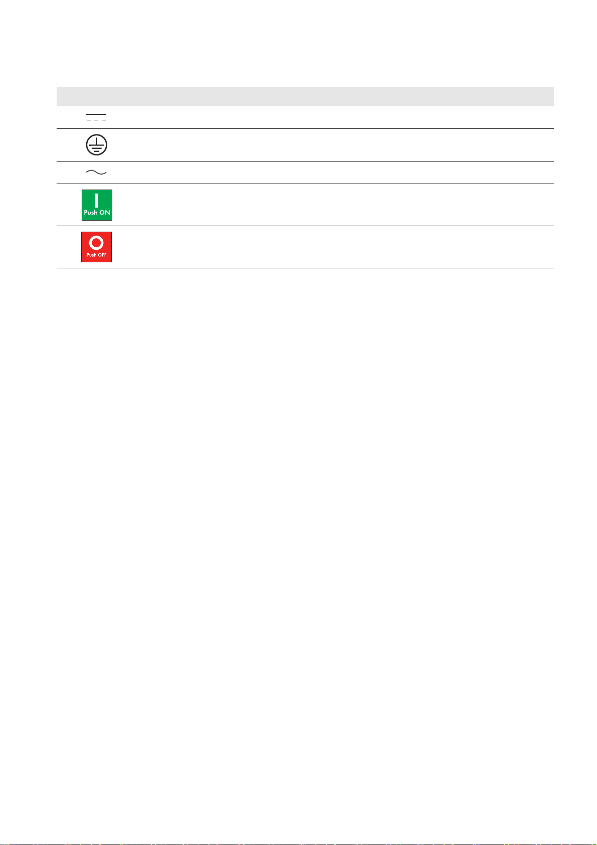
2.4 Symbols on the Sunny Central Inverter
Symbol Explanation
DC current
Earth Ground
AC current
On position of the AC Disconnect
Off position of the AC Disconnect
Operating Manual SCCP-US-BE-US_en-52 17
Page 18
2 Safety SMA America, LLC
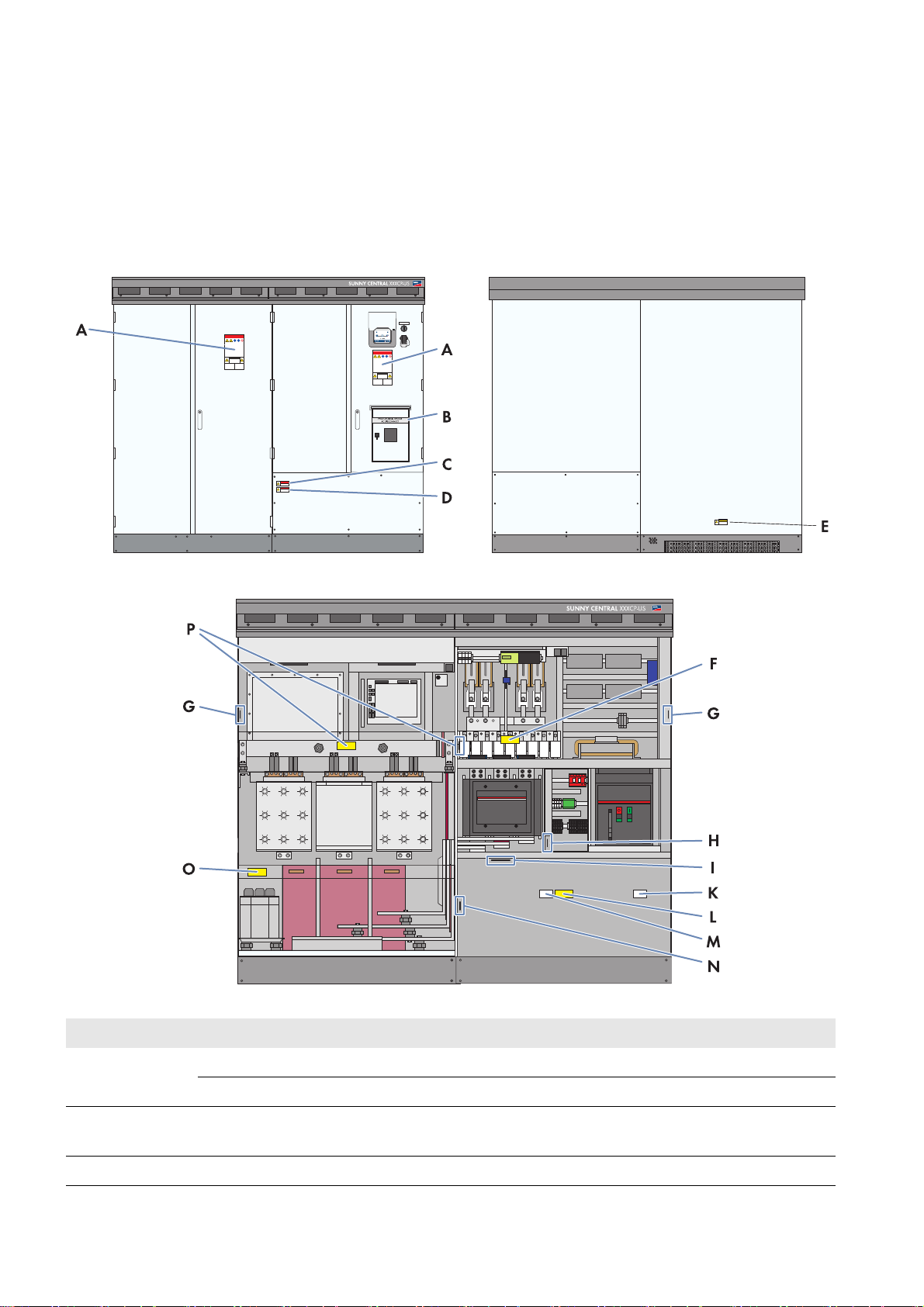
2.5 Labels on the Sunny Central Inverter
This section describes the positions of the labels on the inverter. The warning labels identify potentially hazardous areas
or components. Familiarize yourself with the warning labels and their positions before beginning work on the
inverter.
2.5.1 Inverter without integrated DC switch
Figure1: Safety messages on the inverter
Position SMA order number Description
A 86-0043464 Warning label general SC-US EN
86-430042 Warning label Arc Flash Hazard Protection
B 86-00480030 Only with order option AC Disconnect: Photovoltaic System AC
Disconnect
C 86-00480020 Warning label Arc Flash
18 SCCP-US-BE-US_en-52 Operating Manual
Page 19
SMA America, LLC 2 Safety
Position SMA order number Description
D 86-0043474 Warning label SC-US external transformer EN
E 86-004300 Warning label, Burn Hazard, Hot surface
F 86-0043472 Only for order option DC fuses: Warning label SC-US DC fuses
EN/ES
86-0043473 Only for order option DC fuses: Warning label SC-US DC fuses
EN/FR
G ‒ Type label
H ‒ Label control supply voltage
I 86-10867027 For positive grounding: 1,000 V PV‒
86-430045 For positive grounding: 600 V PV‒*
86-10867028 For negative grounding: 1,000 V PV+
86-430044 For negative grounding: 600 V PV+*
Q 86-0043462 ABC 60Hz
86-101300.1 ABC 50 Hz
L 86-0043470 Warning label SC-US Conductors, EN-FR
86-0043469 Warning label SC-US Conductors, EN-ES
M 86-0043460 Grounding Electrode Terminal
N 86-10867027 For negative grounding or insulated: 1,000 V PV‒
86-430045 For negative grounding or insulated: 600 V PV‒*
86-10867028 For positive grounding or insulated: 1,000 V PV+
86-430044 For positive grounding or insulated: 600 V PV+*
O 86-108680046 Warning label SC US capacitors C1-C3, C6 optional EN/FR
86-108680047 Warning label SC US capacitors C1-C3, C6 optional EN/ES
P 86-0043476 Warning label, SC US stack capacitors EN/ES
86-0043477 Warning label, SC US stack capacitors EN/FR
* For Sunny Central 500CP-US 600V
Replacing warning labels
Missing or damaged warning labels must be replaced. The warning labels can be ordered from SMA using the SMA
order numbers listed above.
Operating Manual SCCP-US-BE-US_en-52 19
Page 20

2 Safety SMA America, LLC
2.5.2 Inverter with integrated DC switch
Figure 2: Warning labels on the Sunny Central inverter
Position SMA order number Description
A 86-0043464 Warning label general SC-US EN
86-430042 Warning label Arc Flash Hazard Protection
B 86-0033325 Label "Closed"
C 86-00480030 Label "Photovoltaic System AC Disconnect"
D 86-101400.1 Label "DC Switch"
E 86-0033324 Label "Open"
F 86-00480020 Warning label Arc Flash
G 86-0043474 Warning label SC-US external transformer EN
H 86-0033326 Warning label Electric Shock due to Live Voltage EN/ES
86-0033327 Warning label Electric Shock due to Live Voltage EN/FR
20 SCCP-US-BE-US_en-52 Operating Manual
Page 21

SMA America, LLC 2 Safety
Position SMA order number Description
I 86-004300 Warning label, Burn Hazard, Hot surface
K 86-0043472 Only for order option DC fuses:
Warning label SC-US DC fuses EN/ES
86-0043473 Only for order option DC fuses:
Warning label SC-US DC fuses EN/FR
L 86-0033321 Warning label Electric Shock Hazard EN/FR
86-0033322 Warning label Electric Shock Hazard EN/ES
M 86-0033329 Warning label Danger: Do not pull out fuses under load EN/FR
86-0033328 Warning label Danger: Do not pull out fuses under load EN/ES
N ‒ Type label
O ‒ Label control supply voltage
P 86-10867027 For positive grounding: 1,000 V PV‒
86-430045 For positive grounding: 600 V PV‒*
86-10867028 For negative grounding: 1,000 V PV+
86-430044 For negative grounding: 600 V PV+*
Q 86-0043462 ABC 60 Hz
86-101300.1 ABC 50 Hz
R 86-0043470 Warning label SC-US conductors, EN-FR
86-0043469 Warning label SC-US conductors, EN-ES
S 86-0043460 Grounding electrode terminal
T 86-10867027 For negative grounding or insulated: 1,000 V PV‒
86-430045 For negative grounding or insulated: 600 V PV‒*
86-10867028 For positive grounding or insulated: 1,000 V PV+
86-430044 For positive grounding or insulated: 600 V PV+*
U 86-108680046 Warning label SC US capacitors C1-C3, C6 optional EN/FR
86-108680047 Warning label SC US capacitors C1-C3, C6 optional EN/ES
V 86-0043476 Warning label, SC US stack capacitors EN/ES
86-0043477 Warning label, SC US stack capacitors EN/FR
* For Sunny Central 500CP-US 600V
Replacing Warning Labels
Replace missing or damaged warning labels. The warning labels can be ordered from SMA using the SMA order
numbers listed above.
Operating Manual SCCP-US-BE-US_en-52 21
Page 22
3 Product Description SMA America, LLC
3 Product Description
This section will give you an overview of the inverter and its components.
3.1 Plant Overview
The Sunny Central CP-US is a PV inverter which converts the direct current generated in the PV modules into grid-compliant
alternating current. An external MV transformer fitted downstream feeds the alternating current generated into the utility
grid.
An AC Disconnect and DC Disconnect must be installed in accordance with NEC ANSI/NFPA 70 and CEC.
The inverter can be optionally ordered with an integrated AC Disconnect and an integrated DC Switch. Both devices are
designed to be used with a lockout device to secure the inverter against reconnection during service. With the AC
Disconnect, the inverter can be disconnected from the utility grid simply and safely. This option does not require an
additional AC Disconnect Unit on the AC side.
With the DC Switch, the inverter can be disconnected from the PV array. If the inverter does not have an integrated DC
Switch, an external DC Disconnect must be installed in accordance with NEC ANSI/NFPA 70 and CEC, in order to be
able to disconnect the inverter from the PV array. This allows you to easily and safely disconnect the inverter as needed.
In some jurisdictions, additional external disconnecting means may be required for servicing of the DC input fuses. SMA
recommends an early review with the AHJ to identify their requirements for the PV System.
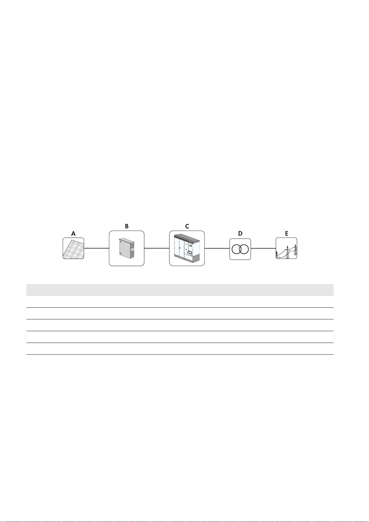
Sunny Central Inverter with Integrated AC Disconnect and Integrated DC Switch
Figure 3: Principle of a grid-connected PV plant with a Sunny Central inverter with integrated AC Disconnect and DC Switch
Position Description
A PV array
B String-Combiner Box
C Inverter with integrated AC Disconnect and DC Switch
DExternal transformer
EUtility grid
22 SCCP-US-BE-US_en-52 Operating Manual
Page 23

SMA America, LLC 3 Product Description
Sunny Central Inverter with Integrated AC Disconnect and external DC Disconnect
Figure 4: Principle of a grid-connected PV plant with an external DC Disconnect and a Sunny Central inverter with integrated AC Disconnect
Position Description
A PV array
BString-Combiner Box
C Inverter with integrated AC Disconnect
D DC Disconnect Unit
E External transformer
FUtility grid
Sunny Central Inverter with External AC Disconnect and External DC Switch
As an option, the AC circuit breaker can be mounted externally.
Circuit breaker
The unit is provided with a UL listed circuit breaker on the output rated 1,600 A for branch circuit protection. If the
circuit breaker shall be located externally to secure the AC path, you have to use the same type of circuit breaker
(ABB Emax E2B-A with 42 kA rated short-circuit current, ABB Emax E2N-A with 65 kA rated short-circuit current or
ABB Emax E2H-A with 85 kA rated short-circuit current and 1,600 A continuous current rating each).
Figure 5: Principle of a grid-connected PV plant with a Sunny Central inverter and external AC / DC Disconnect Unit
Position Description
A PV array
Operating Manual SCCP-US-BE-US_en-52 23
Page 24

3 Product Description SMA America, LLC
Position Description
B String-Combiner Box
C Inverter without Integrated AC Disconnect and without integrated DC Switch
D AC / DC Disconnect Unit
EExternal transformer
FUtility grid
3.2 Sunny Central Inverter
3.2.1 Design of the Sunny Central Inverter
Figure 6: Sunny Central Inverter (example)
Position Description
A Inverter cabinet
B Interface cabinet
C Touch display
DKey switch
E Service interface
F Integrated AC Disconnect*
G Integrated DC Switch*
* depending on the option ordered
3.2.2 Type Label
You can identify the inverter by the type label. Type labels are attached at the top right on the inside of the interface
cabinet and on the top left side of the inverter cabinet. You will find the following information on the type label:
•Device type
• Serial number
•Production version
24 SCCP-US-BE-US_en-52 Operating Manual
Page 25

SMA America, LLC 3 Product Description
•Production date
• Device-specific data
Reading the serial number
You can read the serial number without opening the inverter. The serial number can be found on the roof of the
inverter at the top left. You can also read the serial number from the display.
Reading the firmware version
You can read the version number of the firmware from the inverter and the display via the user interface of the
SC-COM or on the display.
Symbols on the Type Label
Symbol Description Explanation
Danger to life due to high
voltages
Risk of burns due to hot surfaces The product can become hot during operation. Avoid contact
Observe the documentation. Observe all documentation that is supplied with the product.
The product operates at high voltages. All work on the product
must be carried out by qualified persons only.
during operation. Allow the product to cool down sufficiently
before carrying out any work. Wear personal protective
equipment such as safety gloves.
Evaluated to the requirements of the Underwriters Laboratories
Standard for Safety for Inverters, Converters, Controllers and
Interconnection System Equipment for Use With Distributed
Energy Resources, UL 1741.
The inverter has been additionally evaluated by Underwriters
Laboratories to CAN/CSA C22.2 No. 107.1-1,
"General Use Power Supplies".
Operating Manual SCCP-US-BE-US_en-52 25
Page 26

3 Product Description SMA America, LLC
3.2.3 Operating States
The inverter cycles through various states during operation:
Figure 7: Principle overview of the operating states of the inverter
Designation Description
Stop The inverter is switched off. Stop or Remote shutdown active appears in the touch
display.
If the key switch is set to Start, the inverter switches to the "Grid monitoring" operating state.
26 SCCP-US-BE-US_en-52 Operating Manual
Page 27

SMA America, LLC 3 Product Description
Designation Description
Grid monitoring The inverter is in the "Grid monitoring" operating state. Waiting for valid AC grid
appears in the touch display.
The grid limits will be monitored continuously from now on. If a grid fault does not occur
during the grid monitoring time, the AC contactor closes and the inverter switches to the
"Grid monitoring time reached" operating state.
If the grid limits are exceeded during the monitoring time, the inverter will restart "Grid
monitoring".
With the option "Q at Night", the inverter switches to the "Q at Night" operating state if the
time specified in the parameter PvStrT has elapsed and the start voltage PvVtgStrLevMin
has not been reached (see Section 8.3 "Q at Night", page 65).
Grid monitoring time
reached
The inverter is in the "Grid monitoring time reached" operating state. Waiting for PV
voltage or Waiting for electric utility company appears on the touch display.
If the input voltage V
the time specified in the PvStrT parameter elapses. If the input voltage V
exceeds the start voltage PvVtgStrLevMin, the inverter waits until
PV
does not fall
PV
below the start voltage PvVtgStrLevMin during this time, the inverter checks whether the
utility grid is available. If a valid utility grid is available, the inverter switches to the operating
state "Startup".
The start voltage PvVtgStrLevMin must be adjusted to conform with the PV array
connected to the inverter.
Startup The inverter is in the "Startup" operating state. Operation appears in the touch display.
The inverter moves to its initial operating point and begins the grid feed-in process.
MPP load operation In the MPP operating state, the inverter feeds power into the utility grid and operates
permanently at the maximum power point (MPP). Operation and the rate of power feed-in
are shown in the touch display.
If the measured power P
during the time interval PvPwrMinT is less than the minimum
PV
feed-in voltage PvPwrMin or the key switch is set to Stop, the inverter switches to the
"Shutdown" operating state.
With the order option "Q at Night", the inverter switches to the operating state "Q at Night"
if the measured power P
during the time interval PvPwrMinT is less than the minimum
PV
feed-in power PvPwrMin (see Section 8.3 "Q at Night", page 65).
Shutdown The inverter is in the "Shutdown" operating state. Operation appears in the touch display.
If the key switch is set to Stop, the inverter switches to the "Stop" operating state.
The AC contactor and the DC switching device open automatically.
If the inverter shuts down because the feed-in conditions are no longer met,
the inverter switches to the "Grid monitoring" operating state.
Fault If a disturbance occurs during operation, the inverter switches off and displays Fault and
the disturbance in the touch display (see Section 11 "Troubleshooting", page 77).
3.2.4 Touch Display
Different kinds of inverter data can be viewed on the touch display. Settings such as language, time and brightness can
be set, but inverter parameters cannot be set from the touch display.
The display area is activated by touching the touch display. Tapping the symbols on the touch display activates the
corresponding functions. If the touch display is not touched for five minutes, it will shut off.
Operating Manual SCCP-US-BE-US_en-52 27
Page 28

3 Product Description SMA America, LLC
3.2.5 Key Switch
The key switch is used to switch the inverter on and off.
Switch position "Start"
If the key switch is turned to Start, a motor drive automatically switches on the DC switching device and the inverter
switches from the operating state "Stop" to the operating state "Grid monitoring". If there is sufficient irradiation and a
valid utility grid connection, the inverter switches to feed-in operation. If there is insufficient irradiation and the input
voltage is therefore too low, the inverter remains in the operating state "Grid monitoring".
With the "Q at Night" order option, the inverter supports the utility grid with reactive power if the input voltage is
insufficient.
Switch position "Stop"
If the key switch is turned to Stop while the inverter is in the operating state "Grid monitoring", a motor drive automatically
switches off the DC switching device. The inverter switches to the operating state "Stop".
If the key switch is turned to Stop when the inverter is in the operating state "MPP load operation",
the inverter switches to the operating state "Shutdown". Once the shutdown is complete, the AC contactor and the DC
switching device are switched off automatically and the inverter switches to the operating state "Stop".
28 SCCP-US-BE-US_en-52 Operating Manual
Page 29

SMA America, LLC 3 Product Description
3.2.6 Integrated AC Disconnect
Depending on the option ordered, the Sunny Central CP-US inverter may be fitted with an integrated AC Disconnect.
The AC Disconnect enables you to disconnect the inverter from the AC grid in the event an emergency and for service
and maintenance work.
Figure 8: AC Disconnect
Position Description
A OFF button
B ON button
C Spring status indicator
D Position indicator
3.2.7 Integrated DC Switch
Depending on the option ordered, the Sunny Central CP-US inverter may be fitted with an integrated DC Switch. The
DC Switch enables you to disconnect the inverter from the PV array in the event an emergency and for service and
maintenance work. Despite disconnecting the integrated DC Switch, voltages are still present on the DC fuses and the
inverter busbars. Touching the DC fuses or the busbars will result in death or very serious injuries from electric shock.
Figure 9: Integrated DC Switch
Position Description
A Green light repeater
The DC Switch is closed.
BDC switch
Operating Manual SCCP-US-BE-US_en-52 29
Page 30
3 Product Description SMA America, LLC
Position Description
C Red light repeater
The DC Switch is open.
3.3 Sunny Central Communication Controller
The Sunny Central Communication Controller (SC-COM) is the central communication interface of the inverter.
The SC-COM establishes the connection between the inverter and the operator.
Figure 10: SC-COM
Position Description
ASC-COM
The SC-COM collects all data from the connected devices. The SC-COM enables monitoring, parameterization and
remote diagnosis of the inverter via computer, as well as power control by the grid operator.
These various tasks performed by the SC-COM can be organized in two separate networks:
• Monitoring network
This network is used for monitoring, parameterization and remote diagnosis.
•Control network
This network is used by the Power Plant Controller to specifications issued by the grid operator relating to grid
management services to the inverter. The control network is used exclusively for grid management services which are
thus transmitted and implemented within a specified time period.
If only a low bandwidth is required for monitoring the PV plant, the network operator instructions can also be
transmitted via the monitoring network. In this case, only one network is necessary.
The SC-COM makes all data collected available to the operator via an Ethernet connection.
Copper cables or optical fibers can be used for the networks.
Type of communication of the PV plant
The interface of the SC-COM is set by default to COM3 and the baud rate to 115,200. Do not modify these settings.
30 SCCP-US-BE-US_en-52 Operating Manual
Page 31

SMA America, LLC 3 Product Description
3.4 Remote Shutdown
By means of remote shutdown, you can selectively shut down and switch off the inverte r within approximately six se conds,
from a control room for example. The function of the remote shutdown is similar to the stop position of the key switch.
If the remote shutdown function is activated from the control room whilst the inverter is in the operating state
"Grid monitoring", a motor drive automatically shuts off the DC main switch and the inverter switches to the operating
state "Stop".
If the remote shutdown function is activated from the control room while the inverter is in the "MPP load operation"
operating state, the inverter switches to the operating state "Shutdown". Once shutdown is complete, the AC contactor
and the DC main switch are switched off automatically and the inverter goes into the operating state "Stop".
The design of the remote shutdown is wire-break safe. If 24 V is present in the remote shutdown, the inverter continues to
operate in the current operating state. If the remote shutdown function is triggered or if a wire-break occurs, 0 V is present
in the remote shutdown and the inverter switches from its current operating state to the operating state "Stop".
In order to be able to use the remote shutdown, the parameter ExlStrStpEna must be set to On.
3.5 External Fast Stop
The external fast stop is to be used if the inverter is to be disconnected via an external signal in accordance with IEEE
1547 (e.g. External Unintentional Islanding Detection). The inverter comes equipped with a fast stop input. An external
switch that is switched via a 24 V signal can be connected to this fast stop input.
The external fast stop disconnects the inverter from the utility grid in less than 100 ms.
The inverter is delivered with open terminals. The following options are available for configuring the external fast stop:
• The external fast stop deactivated:
The terminals of the active fast stop are bridged. The fast stop function is thus deactivated. Bridging of the terminals
must be performed as necessary.
• The external fast stop is operating with an external 24 V voltage supply.
An external latching switch (break contact) is connected to the inverter terminals via an external 24 V voltage supply.
When the switch is closed, the all-or-nothing relay is activated and the inverter feeds into the grid.
If the fast stop is tripped, the switch opens and the relay is deactivated. The inverter is stopped and no longer feeds
energy into the grid.
Voltage ranges for the relay:
– 24 V to 30 V: The inverter is in operation.
– 0 V to 4 V: The inverter is not in operation.
Tripping of the fast stop function
The fast stop function should only be tripped in the event of immediate danger. Tripping the fast stop will not rapidly
discharge the capacitors. If the inverter is to be switched off and correctly shut down via an external signal, use the
input of the remote shutdown function.
The models SC 850CP-US and SC 900CP-US are only provided with transfer trip functionality to meet unintentional
islanding requirements. An external signal is required to utilize this feature.
Operating Manual SCCP-US-BE-US_en-52 31
Page 32

3 Product Description SMA America, LLC
3.6 Insulation and Ground Fault Monitoring
Types of insulation and ground fault monitoring are described in this section. The type of inverter insulation and ground
fault monitoring depends on the order option.
3.6.1 Operating Principles
The insulation and ground fault monitoring ensures plant protection. The type of monitoring depends on whether the
PV array is grounded or not.
In grounded PV arrays:
The ground fault monitoring is implemented by means of a residual-current monitoring device. If a ground fault occurs,
the residual currents will be detected and interrupted.
• Ground fault on the ungrounded terminal
If a ground fault occurs on the ungrounded pole of the PV array, the normally ungrounded pole of the PV array is
grounded non-specifically by the ground fault and a residual current flows to the grounded pole. This residual current
flows through the ground fault monitoring device, e.g. the GFDI, and triggers it.
• Ground fault on the grounded terminal
The GFDI is bypassed when a ground fault occurs on the grounded terminal of the PV array. The ground fault on the
grounded terminal cannot be reliably detected. A ground fault that occurs unnoticed on the grounded terminal poses
a safety risk. An additional ground fault on the ungrounded terminal leads to higher residual currents that cannot be
interrupted by the ground fault monitoring unit.
Insulation check of the PV array using an insulation monitoring device
In order to ensure the residual current monitoring function in grounded systems, the PV array insulation must be
checked at regular intervals. It is therefore recommended to use an additional insulation monitoring device in
grounded systems. This will allow the insulation to be checked at regular intervals.
In ungrounded PV arrays:
An insulation monitoring device constantly determines the insulation resistance using an active measurement procedure.
As soon as the insulation resistance falls below the warning threshold specified in the insulation monitoring device, an
insulation warning will be given on the touch display. This allows preventative measures to be taken before faults occur
such as risk of injury to personnel due to leakage currents or plant failure. If the insulation resistance falls below the set
warning limiting value, the plant can switch off. The parameter IsoErrIgn can be used to activate or deactivate the
disconnection process under fault conditions.
32 SCCP-US-BE-US_en-52 Operating Manual
Page 33

SMA America, LLC 3 Product Description
3.6.2 Ground Fault Monitoring in Grounded PV Arrays
3.6.2.1 Ground Fault Detection Interruption (GFDI)
Depending on the configuration, ground fault monitoring in the inverter is carried out via ground fault detection
interruption (GFDI). This process is used to ground one pole of the PV array via the GFDI.
GFDI is performed via a high-performance k-type circuit-breaker with adjustable operating current. The GFDI is integrated
in the inverter and connected between an input busbar and the grounding busbar.
Figure 11: GFDI in the inverter
Position Description
AGFDI
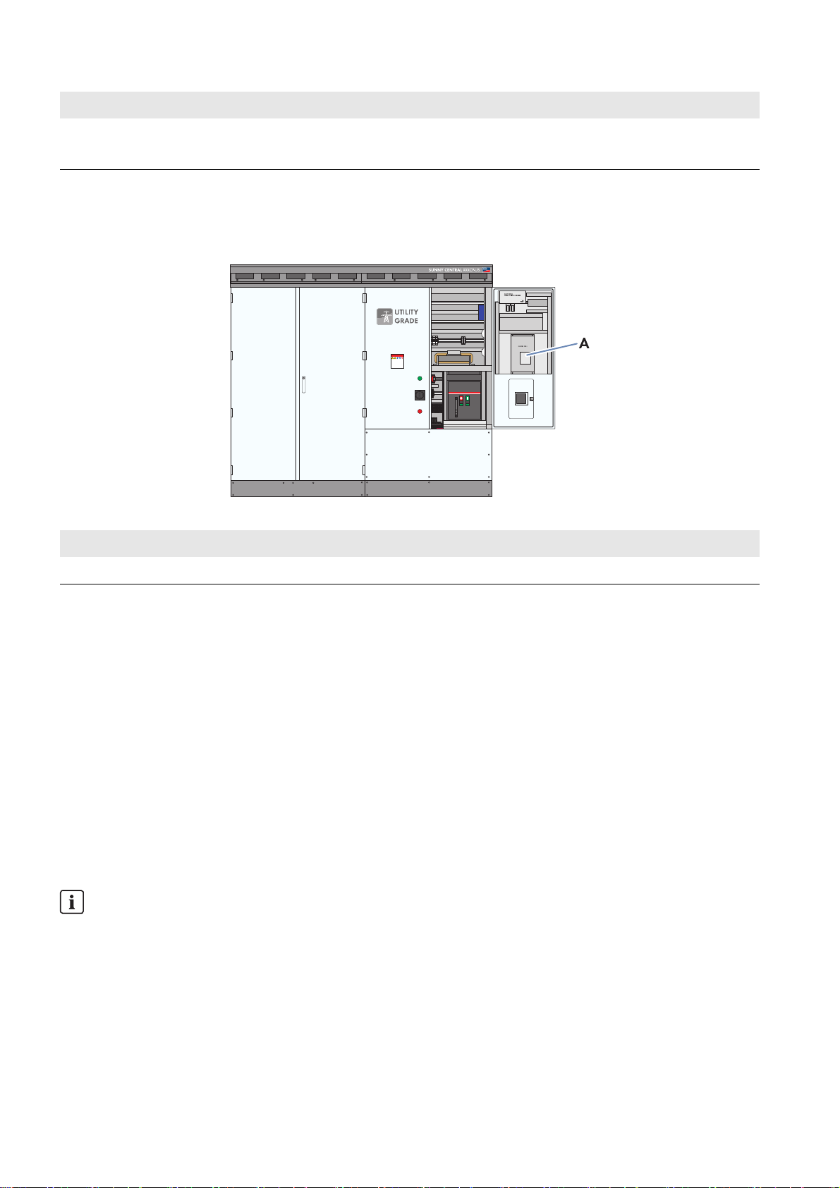
3.6.3 Insulation Monitoring
3.6.3.1 Insulation Monitoring Device
Depending on the configuration, an insulation monitoring device monitors the insulation resistance of the PV plant in
ungrounded utility grids.
In the operating state "MPP load operation", the insulation resistance of the entire system, from the PV modules to the
medium-voltage transformer, will be measured.
If the inverter is in the "Grid monitoring" operating state, only the insulation resistance from the PV modules to the inverter
is measured.
Figure 12: Insulation monitoring device in the inverter
Operating Manual SCCP-US-BE-US_en-52 33
Page 34

3 Product Description SMA America, LLC
A measuring circuit and a relay with a change-over contact are integrated in the insulation monitoring device.
The insulation monitoring device is connected between the PV voltage and the PE protective conductor.
The contacts of the relay are routed to the customer connecting terminal plate and can be used by the customer to trip a
signal light or horn. The characteristics of the relay are indicated in the circuit diagram.
If the insulation resistance falls below the warning threshold specified in the RisoCtlWarn parameter, the measuring
circuit closes and the LED ALARM1 on the insulation monitoring device lights up. The error message 3601‒ Warning
insulation error is generated by the inverter. Simultaneously, the insulation monitoring device activates the relay with
changeover contact. This relay is installed in the inverter.
If the insulation resistance falls below the error threshold (1 kΩ), an insulation error has occurred and the LEDs ALARM1
and ALARM2 on the insulation monitoring device light up. In this case, the operating behavior of the inverter can be set
via parameters:
• If the parameter IsoErrIgn is set to Off, the measuring circuit issues a disturbance when the insulation resistance falls
below the error threshold, the inverter switches off and issues the error message 3501 - Insulation error. The LEDs
ALARM1 and ALARM2 are glowing.
• If the parameter IsoErrIgn is set to On, the error message from the measuring circuit is ignored when the insulation
resistance falls below the error threshold. The inverter continues to fee d into the grid and generates the error message
3504 ‒ Insulation error ignored.
• If the parameter IsoErrIgn is set to Run and the insulation resistance falls below the error threshold, the error
message from the measuring circuit will only be ignored if the inverter is in feed-in operation. In feed-in operation,
the inverter continues to feed in and issues the error message 3504 ‒ Insulation error ignored. If the insulation
resistance falls below the error threshold in another operating state, the error is not ignored and the inverter does
not go into feed-in operation. The error message 3501 ‒ Insulation error appears on the touch display. The LEDs
ALARM1 and ALARM2 are glowing.
Type of insulation monitoring device used
The insulation monitoring device used is the A-ISOMETER iso-PV1685 device supplied by Bender GmbH & Co. KG.
3.6.4 Combined Insulation and Ground Fault Monitoring
3.6.4.1 GFDI and Insulation Monitoring
With the "GFDI and Insulation Monitoring" order option, it is possible to temporarily disable the PV array grounding and
to check the insulation via the integrated insulation monitoring device.
When the GFDI is closed, the PV array is grounded In this state, the insulation resistance cannot be determined.
If the GFDI is open, the grounding connection is disabled. In this state, the insulation monitoring device continuously
measures the insulation resistance. In the operating state "MPP load operation", the insulation resistance of the entire
system, from the PV modules to the medium-voltage transformer, will be measured. If the inverter is in the operating state
"Grid monitoring", only the insulation resistance of the PV modules up to the inverter will be measured.
Insulation monitoring should be performed in the operating state "MPP load operation" This ensures that all parts of the
plant are included in the insulation measurement.
The parameter for insulation monitoring allows you to configure how an error message in the insulation monitoring device
will affect the operating behavior of the inverter:
• If the parameter IsoErrIgn is set to Off, the measuring circuit issues a disturbance when the insulation resistance falls
below the error threshold, the inverter switches off and issues the error message 3501 - Insulation error. The LEDs
ALARM1 and ALARM2 are glowing.
• If the parameter IsoErrIgn is set to On, the error message from the measuring circuit is ignored when the insulation
resistance falls below the error threshold. The inverter continues to fee d into the grid and generates the error message
3504 ‒ Insulation error ignored.
• If the parameter IsoErrIgn is set to Run and the insulation resistance falls below the error threshold, the error
message from the measuring circuit will only be ignored if the inverter is in feed-in operation. In feed-in operation,
the inverter continues to feed in and issues the error message 3504 ‒ Insulation error ignored. If the insulation
34 SCCP-US-BE-US_en-52 Operating Manual
Page 35

SMA America, LLC 3 Product Description
resistance falls below the error threshold in another operating state, the error is not ignored and the inverter does
not go into feed-in operation. The error message 3501 ‒ Insulation error appears on the touch display. The LEDs
ALARM1 and ALARM2 are glowing.
Insulation monitoring
The insulation monitoring device will start measuring once the GFDI is open. The device will initially assume that the
insulation is poor. If the parameter IsoErrIgn is set to Off, the inverter will switch off temporarily.
After approximately five minutes, the insulation monitoring device will have determined the correct insulation resistance
and the value of the insulation resistance can be viewed on the display of the in sulation monitoring device. If the insulation
is intact, the inverter switches back to the operating state "MPP load operation". If the insulation monitoring process is
complete, the GFDI should be closed again and thus allow the PV array to operate with a grounded connection.
If, after approximately five minutes, one of the errors 3501 ‒ Insulation Failure, 3504 ‒ Insulation failure ignored,
or 3601 ‒ Warning insulation failure is displayed, then the insulation is defective. In this case, an electrically qualified
person needs to check and, if necessary, repair the insulation and then acknowledge the error.
Type of insulation monitoring device used
The insulation monitoring device used is the A-ISOMETER iso-PV1685 device supplied by Bender GmbH & Co. KG.
3.6.4.2 Advanced Remote GFDI and Insulation Monitoring Device
With the "Advanced Remote GFDI and Insulation Monitoring US" order option, it is possible to temporarily disable the
PV array grounding and to check the insulation via the integrated insulation monitoring device.
Figure 13: Advanced Remote GFDI in the inverter
When the remote GFDI is closed, the PV array is grounded. In this state, the insulation resistance cannot be determined.
The Advanced Remote GFDI opens in the event of:
• Disturbance, e.g. ground faults
• Manual activation of the plant maintenance
• Automatic plant maintenance
Each switching process of the Advanced Remote GFDI is counted in the CntGfdiSw instantaneous value.
Disturbance
If a ground fault occurs, the inverter opens the Advanced and stops the feed-in operation. The AC and DC switching
devices are opened. The inverter displays the error 3502 - Ground Fault Detected. After a waiting time of
approximately 15 minutes has expired, the insulation monitoring is activated.
You must close the Advanced Remote GFDI manually via the parameter RemMntSvc or the key switch(see
Section 10.1.3, page 76). To be able to do this, all errors must be confirmed.
Operating Manual SCCP-US-BE-US_en-52 35
Page 36

3 Product Description SMA America, LLC
Manually ending plant maintenance
The automatic resetting of the parameter RemMntSvc after a ground fault results in the loss of the UL listing.
If an insulation error has been detected, the Advanced Remote GFDI cannot be closed via the parameter RemMntSvc.
In this case, a qualified person needs to check and, if necessary, repair the insulation and then acknowledge the error.
Manual activation of the plant maintenance
Manual plant maintenance can be activated via the parameter RemMntSvc (see Section 10.1.2, page 76).
If the manual plant maintenance is activated, the inverter opens the Advanced Remote GFDI and the AC switching device.
The DC switching device remains closed. The inverter displays the warning 3517 ‒ Isolated mode, isolation
detection. After a waiting time of approximately 15 minutes has expired, the insulation monitoring is activated.
Manual plant maintenance can be ended via the parameter RemMntSvc (see Section 10.1.3, page 76).
Automatic plant maintenance
Depending on the configuration option, automatic plant maintenance is activated. In this case the inverter performs an
automatic insulation measurement in the morning before switching to feed-in operation.
If in the morning the voltage of the PV array exceeds the value set in the parameter PvVtgRisoStart, automatic plant
monitoring begins.
If the automatic plant maintenance is activated, the inverter opens the Advanced Remote GFDI. The AC switching device
is opened and remains open until completion of the plant maintenance. The DC switching device remains closed.
The inverter displays the warning 3517 ‒ Isolated mode, isolation detection. After a waiting time of approximately
15 minutes has expired, the insulation monitoring is activated.
If there is no insulation error present, the automatic plant maintenance can be interrupted via the key switch.
If the voltage of the PV array exceeds the sum of the values of PvVtgStrLevMin and PvVtgRisoDif, a waiting time of
approximately 15 minutes has elapsed and there are no insulation errors present, the inverter ends the automatic plant
maintenance and switches into feed-in operation.
Insulation monitoring
If the error message 3501 ‒ Insulation Failure is displayed, the insulation is defective. In this case, a qualified person
needs to check and, if necessary, repair the insulation and then acknowledge the error.
Once the error has been corrected, the plant maintenance can be ended via the parameter RemMntSvc
(see Section 10.1.3, page 76).
Type of insulation monitoring device used
The insulation monitoring device used is the A-ISOMETER iso-PV1685 device supplied by Bender GmbH & Co. KG.
36 SCCP-US-BE-US_en-52 Operating Manual
Page 37

SMA America, LLC 3 Product Description
3.7 Grid Management Services
3.7.1 Requirements
PV plants must participate in feed-in management in accordance with IEEE 1547. First and foremost, the grid operator
must be able to limit the power of the PV plant by remote control and temporarily reduce it to zero in critical cases.
The grid operator's relevant control commands must therefore be transmitted to the inverter quickly and reliably for
implementation.
The following figure shows how the specifications of the grid operator are implemented. The Power Reducer Box sends
the specifications of the grid operators to the inverter.
Figure 14: Principle of grid integration
Besides the Power Reducer Box, there are two other options for meeting the requirement of grid management:
• Receiving the signals via two analog inputs on the inverter
• Manually adjusting the specifications via parameters
3.7.2 Active Power Limitation
There are five methods of limiting active power independently of power frequency. The limit can be configured by means
of a parameter or supplied by the grid operator as an external signal(see Section 7.2, page 53).
In addition to these methods, the active power can also be limited as a function of the power frequency (see Section 7.1,
page 52).
3.7.3 Reactive Power Setpoint
The inverter can provide reactive power. There are eleven methods for selecting the setp oint. They include entering a fixed
parameter, processing an external signal from the grid operator or specifying the reactive power using adjustable
characteristic curve parameters (see Section 8, page 56).
3.7.4 Full and Limited Dynamic Grid Support (FRT)
With full dynamic grid support, the inverter supports the utility grid during a brief grid voltage drop by feeding in reactive
current. In this case, the behavior of the inverter depends on the percentage ratio of line voltage V
V.
to nominal voltage
Grid
Operating Manual SCCP-US-BE-US_en-52 37
Page 38

3 Product Description SMA America, LLC
With limited dynamic grid support, the inverter interrupts the grid feed-in during the grid voltage drop.
Figure 15: Maximum duration of a voltage dip that the inverter can work through without disconnecting from the utility grid
Ratio V
90% to 100% The ratio of line voltage V
/V Behavior of the inverter
Grid
to nominal voltage V is in the normal range and the inverter feeds in
Grid
without any problem.
20% to 90% The ratio of line voltage V
to nominal voltage V is in the critical range. There is a disturbance
Grid
in the utility grid.
While this disturbance remains present, the inverter supports the electricity grid with reactive
current.
The inverter can bridge disturbances of up to two seconds without disconnecting from the utility
grid.
If the set grid monitoring time is ex ceeded during this period, the inverter disconnects from the utility
grid.
0% to 20% The ratio of line voltage V
to nominal voltage V is in the critical range. There is a disturbance
Grid
in the utility grid.
While this disturbance remains present, the inverter supports the electricity grid with reactive
current.
The inverter can bridge disturbances of up to one second without disconnecting from the utility grid.
The requirement is that the relationship V
/V was >= 90% before the error occurred.
Grid
If the set grid monitoring time is ex ceeded during this period, the inverter disconnects from the utility
grid.
The operating mode of the dynamic grid support is set via the parameter FRTMod. With this, the full dynamic grid support
(FRT_BDEW), the full dynamic grid support with FRT characteristic curve (FRT_SDLWindV) and the limited dynamic grid
support (FRT_Partial) can be selected.
The level of reactive current provided during full dynamic grid support is determined via the parameter FRTArGraNom.
The level of reactive current provided during full dynamic grid support with FRT characteristic curve is determined via the
parameters FRT2ArGraNomHi and FRT2ArGraNomLo.
38 SCCP-US-BE-US_en-52 Operating Manual
Page 39

SMA America, LLC 3 Product Description
Contact the SMA Service Line to activate the function "FRT" and to change the operating mode. Contact the SMA Service
Line before setting the FRTArGraNom parameter to a value greater than 2.
Full and limited dynamic grid support and islanding detection
The function "FRT" cannot be active at the same time as the function "Active Islanding Detection". If the "FRT" function
is activated , the "Active Island Detection" function is deactivated automatically. Changing this parameter therefore
results in the loss of the UL listing.
The "FRT" function can be active at the same time as the "External Islanding Detection" function. For this, the
parameters VCtllLimTm and VCtlllLimTm must be set to 2,000 ms.
3.7.5 Decoupling Protection Ramp
After a grid error, the inverter restarts at a maximum of 10% of nominal power per minute using a decoupling protection
ramp. You have the option of switching this decoupling protection ramp on or off. If you deactivate the decoupling
protection ramp, the inverter runs up to the maximum power in the shortest time possible. If you wish to deactivate the
decoupling protection ramp, contact the SMA Service Line.
3.7.6 Grid Management Shutdown
If the utility grid becomes unstable and overloaded, the grid management service requires that the inverter disconnects
from the grid immediately. In such cases, the relevant signal will be sent by the grid operator or the safety system at the
grid transfer point. The inverter disconnects from the utility grid immediately and displays the error message 9013. The
error will be reset in the inverter after a corresponding signal is sent by the grid operator or the transfer point's safety
system.
Operating Manual SCCP-US-BE-US_en-52 39
Page 40

3 Product Description SMA America, LLC
3.7.7 Q at Night
(
Q at Night is not UL listed
The order option "Q at Night" is not part of the UL 1741 listing, but may be used without loss of inverter certification
if permitted by the Authority Having Jurisdiction (AHJ).
With the configuration option "Q at Night", the inverter can provide reactive power in order to stabilize the utility grid
during non-feed-in operation, e.g. at night. This function is independent of normal feed-in operation.
Only limited dynamic grid support is available in the operating state "Q at Night".
Figure16: General overview of the operating states of the inverter in the operating state "Q at Night"
If the AC power generated by the inverter falls below 5 kW, the inverter switches from feed-in operation to "Q at Night"
operation. The inverter feeds in reactive power in accordance with the parameters set. Since this status can also occur
during the day, the DC switchgear remains closed at first in order to avoid unnecessary switching of the DC switchgear.
If the inverter has been in the "Q at Night" operation for one hour or the DC current falls below 60 A, the DC switchgear
opens. The inverter continues to feed in reactive power.
If reactive power feed-in is interrupted after a grid fault and the AC contactor is opened while the DC switchgear is open,
the DC circuit is initially pre-charged. This reduces the stress on the electronic components. This procedure requires a
maximum of one minute. Once the DC circuit is sufficiently pre-charged, the AC contactor is closed and the inverter
monitors the grid limits. If all of the feed-in requirements are met, the inverter starts reactive power feed-in again within
one minute.
While the inverter is feeding in reactive power, the inverter monitors at the same time whether the conditions for active
power feed-in have been met. If the feed-in requirements are met, the inverter closes the DC switchgear and switches to
feed-in operation.
The amount of reverse current is set to -60 A by default in the parameter QoDInvCurPv to protect the PV array.
This value should be adjusted according to the maximum permissible reverse current of the PV array.
40 SCCP-US-BE-US_en-52 Operating Manual
Page 41

SMA America, LLC 3 Product Description
3.8 Islanding Detection
Stand-alone grids form when the following conditions occur simultaneously:
• The medium-voltage grid fails.
• The inverter feeds in an amount x of power. There is an electrical load on the same branch of the grid with a load
equal to that of power x.
There are two methods for islanding detection:
• Active Islanding Detection*
• External Islanding Detection
Active Islanding Detection
The inverter detects the formation of stand-alone grids during a grid failure and disconnects the inverter from the utility
grid.
This function is set via the parameter EnaAID and cannot be active at the same time as the "FRT" function.
External Islanding Detection
In the event of a grid failure, the formation of stand-alone grids is detected at the farm level. If a stand-alone grid is formed,
a signal is transmitted to the fast stop input of the inverter.
If the signal appears at the fast stop input of the inverter while the inverter is in the "MPP load operation" operating state,
the inverter switches to the operating state "Shutdown". Once shutdown is complete, the AC contactor and the DC
switching device open automatically and the inverter switches to the operating state "Stop".
For external islanding detection, a suitable cable must be connected to the inverter fast stop input during installation.
3.9 Schematic Diagram
Schematic diagrams in PDF format contain jump marks. By double clicking a jump mark, the display will change to the
corresponding current path or the referenced place in the equipment list.
SMA recommends using schematic diagrams in PDF format during troubleshooting. The schematic diagrams in PDF
format are available on request. Contact the SMA Service Line.
* Not with SC 850CP-US and SC 900CP-US
Operating Manual SCCP-US-BE-US_en-52 41
Page 42

4 Touch Display of the Inverter SMA America, LLC
4 Touch Display of the Inverter
4.1 Touch Display Layout
The touch display of the inverter is used to display instantaneous values and parameter settings.
The functions are activated by tapping on the appropriate symbols on the touch display.
The touch display is divided into three areas.
Figure 17: Touch display areas
Position Description
A Status info line
B Information area
C Navigation line
4.2 Explanation of Symbols
4.2.1 Status Info Line
Figure 18: Structure of the status info line
42 SCCP-US-BE-US_en-52 Operating Manual
Page 43

SMA America, LLC 4 Touch Display of the Inverter
Position Description
A Number of the active menu
B Symbol indicating whether the inverter is currently password-protected or is available for configuration.
C Date and time display
4.2.2 Information Area
Main Menu
You can access the following sub-menus and screens from the main menu:
Symbol Description Explanation
E-today line graph Select this symbol to see the energy fed-in during the current day in kWh.
E-total bar chart Select this symbol to see the energy fed-in over the last 14 days in kWh.
DC side Select this symbol to see the following instantaneous values:
•PV power in W
• Insulation resistance in Ω
• PV current in A
•PV voltage in V
The symbol also appears on the page that opens. Select this symbol to see the
sub-menu level diagrams.
Switch on DC side or
AC side is closed
Switch on DC side or
AC side is open
Status of switches on
DC side or AC side is
not known
Inverter data Select this symbol to see the following data:
If you see this symbol between the "DC side" symbol and the "Inverter data"
symbol, the DC switching device is closed.
If you see this symbol between the "Inverter data" symbol and the "AC side"
symbol, the AC contactor is closed.
If you see this symbol between the "DC side" symbol and the "Inverter data"
symbol, the DC switching device is open.
If you see this symbol between the "Inverter data" symbol and the "AC side"
symbol, the AC contactor is open.
If you see this symbol between the "DC side" symbol and the "Inverter data"
symbol, the switch status of the DC switching device is not known.
If you see this symbol between the "Inverter data" symbol and the "AC side"
symbol, the switch status of the AC contactor is not known.
• Device type
• Operating state
• Symbol for utility grid menu
• Symbol for temperature display
• Symbol for fan display
Operating Manual SCCP-US-BE-US_en-52 43
Page 44

4 Touch Display of the Inverter SMA America, LLC
Symbol Description Explanation
AC side Select this symbol to see the following instantaneous values:
•Active power in W
•Reactive power in VAr
• Power frequency in Hz
• Alternating current in A
•AC voltage in V
Grid Select this symbol to display the following on the first page of the menu:
• Active procedure for active power limitation(see Section 7 "Active Power
Limitation", page 52)
• Target active power in kW
•Actual active power in kW
Select to see the following data on the second menu page:
• Active procedure for reactive power setpoint (see Section 8 "Reactive Power
Control", page 56)
• Target reactive power in VAr
• Target displacement power factor cos φ
• Target excitation type of the displacement power factor
• Actual reactive power in VAr
• Actual displacement power factor cos φ
• Actual excitation type of the displacement power factor
Settings Menu
To access the settings menu, tap the corresponding symbol in the navigation bar.
Symbol Description Explanation
Language selection Select this symbol to open the language selection menu (see Section 4.3, page 46).
Contrast setting Select this symbol to open the contrast setting menu (see Section 4.6, page 46).
Time setting Select this symbol to open the time setting menu (see Section 4.4, page 46).
Format selection Select this symbol to open the format selection menu (see Section 4.5, page 46).
Password entry Select this symbol to open the password entry menu (see Section 4.7, page 47).
44 SCCP-US-BE-US_en-52 Operating Manual
Page 45

SMA America, LLC 4 Touch Display of the Inverter
Diagrams of the main menu level and sub-menu level
Select the symbol to see the sub-menu level diagrams. The data displayed depends on the menu in which you select
the symbol.
Number of the active menu Data displayed
103 Energy fed in by the inverter during the current day
104 Energy fed in by the inverter during the last 14 days
132 to 133 Group currents of the individual inverter String-Monitors
140 to 146 String currents of the individual inverter String-Monitors
4.2.3 Navigation Line
Symbol Description Explanation
Back Select this symbol to go back to the previous page.
Homepage Select this symbol to go to the homepage.
Settings Select this symbol to access the following symbols:
• - Language selection
• - Brightness setting
• - Time setting
• - Format selection
• - Password entry
Information Select this symbol to see the following information:
• OS: Version of the operating system
• App.: Version of the application software
• Language: Selected language
• Ser.No.: Serial number of the inverter
Error This symbol appears when an error occurs.
The symbol is displayed both in the symbol where the error has occurred and in the
menu bar.
Select this symbol from the menu bar to see the following data:
• ErrNo: Error number
• TmsRmg: Time until reconnection
• Msg: Error message
• Dsc: Corrective measure
Service The symbol appears when you should contact the SMA Service Line.
The symbol appears when you should have the error corrected by your installer.
Contact your installer.
Operating Manual SCCP-US-BE-US_en-52 45
Page 46

4 Touch Display of the Inverter SMA America, LLC
4.3 Selecting the Language
1. Select .
2. Select .
3. Select the language based on the country symbols.
4. Confirm entry by selecting .
4.4 Changing the Date, Time, and Time Zone
SC-COM accepts changes
The SC-COM will accept date, time or time zone changes made on the touch display.
Procedure:
1. Select .
2. Select .
3. To change the date, select the day, month and year in the field. Use the
and buttons to change the day, month and year.
4. To change the time, select the hour, minute and second one after another in the field. Use and to change
the hours, minutes and seconds.
5. To change the time zone, select a time zone in the field. Use the and buttons to change the time zone.
4.5 Selecting the Display Format
1. Select .
2. Select .
3. Select the date format.
4. Select the hour format.
5. Select the number format.
6. Confirm entry by selecting .
4.6 Setting the Brightness
1. Select .
2. Select .
3. Set the brightness. Select for a darker screen or for a lighter screen.
4. Confirm entry by selecting .
46 SCCP-US-BE-US_en-52 Operating Manual
Page 47

SMA America, LLC 4 Touch Display of the Inverter
4.7 Entering the Installer Password
Installer access
The "Installer" access level is activated by entering the installer password.
The access level will be reset after 15 minutes.
Procedure:
1. Select .
2. Select .
3. Enter the installer password. Use the keypad to do this.
4. Confirm entry by selecting .
☑ The symbol appears in the status info line.
✖ The status info line does not show the symbol?
An incorrect password was entered.
• Enter the password again.
Operating Manual SCCP-US-BE-US_en-52 47
Page 48

5 Plant Network SMA America, LLC
5 Plant Network
5.1 Plant Network Structure
In order to connect the inverter to a computer via the service interface or via the Internet, the SC-COM must be set up in
the plant network. To allow multiple inverter devices to operate on the same network, the SC-COM of each inverter must
be assigned a unique network address.
Figure 19: Plant network of two Sunny Central inverters with touch display (example)
48 SCCP-US-BE-US_en-52 Operating Manual
Page 49

SMA America, LLC 5 Plant Network
Figure 20: Basic structure of large-scale plant networks
5.2 Setting the IP Address on the Laptop
Before the laptop can communicate with the inverter, you must set the laptop network settings to those of the
inverter.
Administrator rights in the operating system
You will need the appropriate administrator rights in order to be able to change the laptop network settings.
• For questions about administrator rights, contact your network administrator.
Procedure:
1. Make a note of the laptop IP address.
2. Adjust the IP address of the laptop to the address range of the inverter.
Operating Manual SCCP-US-BE-US_en-52 49
Page 50

5 Plant Network SMA America, LLC
5.3 Configuring the IP Address of the Inverter for Static Networks
The inverter has 3 LAN interfaces for connecting nodes.
• The inverter-internal network is available via LAN1. The network settings for this interface are preset and cannot be
changed. The default IP address of the LAN1 interface is 192.168.100.2.
• The control network is available via LAN2. Here the SC-COM receives the setpoint specifications of the grid operator
and forwards these specifications to the inverter. The default IP address of the LAN2 interface is 10.112.4.1.
• The monitoring network is available via LAN3. The inverter sends data via this interface to Sunny Portal or the OPC
client, for example, for visualization and analysis purposes. The default IP address of the LAN3 interface is
10.111.1.1.
Procedure:
1. Log in to the user interface.
2. Select Sunny Central > Settings > Network.
3. In the IP address field, enter the static IP address that you want to use to access the inverter in the local network.
4. Enter the subnet mask of your network in the Subnet mask field.
5. Enter the gateway IP address of your network in the Gateway address field. Usually, the IP address of the router
has to be entered here.
6. Enter the IP address of the DNS server (Domain Name System) in the DNS server address field. Usually, the IP
address of the router has to be entered here.
7. Select [Save] and [Confirm].
5.4 Configuring the IP Address of the Inverter for Dynamic Networks
The inverter can obtain the network settings from a DHCP server. The IP address, subnet mask, gateway and
DNS server are automatically obtained from the DHCP server during startup of the inverter.
Use of DHCP
Before setting the inverter to dynamic IP address assignment, check your DHCP server. The DHCP server must extend
the lease of the assigned IP address. Do not use the DHCP server if it assigns a new IP address after the lease has
expired. DHCP servers can normally list all devices to which you have assigned an IP address. You can now identify
the inverter via its MAC address. The MAC address of your inverter can be found on the type label or by selecting
Sunny Central > Info in the user interface.
Procedure:
1. Log in to the user interface.
2. Select Sunny Central > Settings > Network.
3. Activate DHCP in the IP address field.
4. Select [Save].
50 SCCP-US-BE-US_en-52 Operating Manual
Page 51

SMA America, LLC 6 Communication with the SC-COM
6 Communication with the SC-COM
This section provides you with an overview of the options on how you can display inverter measured values, change
parameters for inverter operation and add new hardware components to the PV plant communication.
6.1 Displaying Instantaneous Values
The SC-COM operating manual contains a detailed description of the SC-COM user interface.
Procedure:
1. Log in to the user interface.
2. Enter the password in the appropriate field on the homepage and confirm with [Login].
3. Select Data > Devices.
4. Select .
☑ A list of existing device types appears.
5. Select the desired device type.
☑ A list appears containing all existing devices of this type.
6. Select the desired device from the list.
7. Select the Instantaneous values tab.
6.2 Changing Parameters
Parameters are changed via the user interface. You can access the inverter either on-site via a laptop or remotely via a
computer.
Procedure:
1. Log in to the user interface.
2. Enter the installer password in the appropriate field on the homepage and confirm with [Login].
3. Select Data > Devices.
4. Select .
☑ A list of existing device types appears.
5. Select the desired device type.
☑ A list appears containing all existing devices of this type.
6. Select the desired device from the list.
7. Select the Parameter tab.
8. Change the desired parameter.
9. Confirm the parameter entry with [Save].
6.3 Setting the Remote Shutdown
The inverter can be switched off and shut down via an external signal. Two 24 V terminals are connected to the customer
connecting terminal plate for this purpose (see the Sunny Central installation manual supplied with the inverter).
To use this function, the associated parameter must be activated.
Procedure:
1. Ensure that the inverter is in the "Stop" operating state.
2. Log in to the user interface.
3. Enter the password in the appropriate field on the homepage and confirm with [Login].
4. Set the ExlStrStpEna parameter on the user interface to On (see Section 6.2 "Changing Parameters", page 51).
5. Confirm the parameter entry with [Save].
Operating Manual SCCP-US-BE-US_en-52 51
Page 52

7 Active Power Limitation SMA America, LLC
/05*$&
7 Active Power Limitation
The inverter can limit its active power if requested by the grid operator. The limitation of the active power can be
performed both dependent on the power frequency and independent of the frequency.
The frequency-dependent active power limitation is regulated in accordance with the specifications of IEEE 1547 and
cannot be changed. This Section describes the function and parameterization of both types of active power limitation.
Operation failure of the inverter due to incorrectly set parameters
If the parameter settings for grid management services are incorrect, the inverter may not be able to meet the grid
management requirements. This may lead to yield losses and disconnection of the inverter by the grid operator.
• When setting the mode of grid management services, ensure that the control procedures are parameterized as
agreed with the grid operator.
•
7.1 Power Frequency-Dependent Active Power Limitation
In addition to the procedures for active power limitation that can be chosen using the P-WMod parameter, active power
can be limited dependent on the power frequency.
During active power limitation via the power frequency, the inverter constantly checks the connected power frequency.If
the active power is to be limited by a hysteresis, the parameter WCtlHzMod must be set to CurveHys.
Figure 21: Inverter behavior when exceeding the P-HzStr frequency limit
If the power frequency exceeds a limiting value defined in the parameter P-HzStr, shown here under point A,
the inverter will save the current feed-in power P
The reduction of the feed-in power is defined via the P-WGra parameter. This parameter indicates the percentage of the
saved power P
If the power frequency decreases again as shown here under point B, the last feed-in power reached will remain valid.
Only if the power falls below the limiting value defined in the parameter P-HzStop, shown here in point C, can the
amount of power fed in be increased again. The saved value P
threshold for power frequency shortfall can be defined with the parameter P-HzStopMin, shown here at point D.
52 SCCP-US-BE-US_en-52 Operating Manual
by which the power per Hz will be reduced if the power frequency continues to rise.
cur
. The reduced feed-in power is calculated based on this saved value.
cur
will be rendered invalid. In addition, a minimum
cur
Page 53

SMA America, LLC 7 Active Power Limitation
If the power frequency exceeds the grid limit, the inverter will shut down and switch over to the "Grid monitoring"
operating state. The inverter will remain in the "Grid monitoring" operating state until all feed-in conditions are fulfilled
again.
Calculating the active power limit:
Formula: P
P
lim
P
cur
f
power
lim
= P
– ( (f
cur
power
Power limit
Current power
Power frequency
– P-HzStr) * P-WGra * P
cur
)
P-HzStr Selected frequency limit at which the feed-in power will be reduced
P-WGra Gradient for reducing active power
Example:
A inverter with 500 kW is feeding 350 kW (P
) into the utility grid. The frequency will reach up to 61.2 Hz.
cur
The difference between the current power frequency and P-HzStr (61.2 Hz - 60.2 Hz) multiplied by the gradient
P-WGra (40%/Hz) results in an active power reduction of 40% in the last available power P
(350 kW). This results
cur
in a power limitation of 140 kW and a maximum active power of 210 kW.
Calculation:
210 kW = 350 kW – ( (61.2 Hz – 60.2 Hz) * 40 %/Hz * 350 kW )
7.2 Active Power Limitation Independent of the Frequency
7.2.1 Selecting the Procedure with the Parameter P-WMod
You can set the active power limitation via the parameter P-WMod (see Section 6.2 "Changing Parameters", page 51).
Use the parameter to configure how the specifications of the grid operator are to be received and implemented. The
default setting for this parameter is Off.
Parameter blocking
The parameter P-WMod may only be changed in the operating state "Stop". The entry will not be accepted in other
operating states.
There are five different procedures for power frequency-independent active power limitation:
Procedure Description
Off The active power is limited to the device nominal power Pmax.
WCtlCom The active power limitation is received by the SC-COM via Modbus and then transmitted to the
inverter.
WCnst The active power limitation is entered as an absolute value via the parameter P-W.
WCnstNom The active power limitation is entered as a percentage value via the parameter P-WNom.
WCnstNomAnIn The active power limitation is set at the input terminals using an analog signal for the setpoint.
Active Power Limitation Procedure and Setting Associated Parameters
1. Ensure that the inverter is in the "Stop" operating state.
2. Log in to the user interface.
3. Enter the password in the appropriate field on the homepage and confirm with [Login].
4. Change the parameter P-WMod in the user interface. Select the desired procedure from the list (see Section 6.2
"Changing Parameters", page 51).
5. Change parameters belonging to the selected procedure.
Operating Manual SCCP-US-BE-US_en-52 53
Page 54

7 Active Power Limitation SMA America, LLC
6. Confirm the parameter entry with [Save].
7.2.2 Off Procedure
The feed-in power is limited to the parameter Pmax.
The parameter Pmax defines the nominal power of the inverter and is set to the local conditions during commissioning.
Before the parameter Pmax can be changed, the device must be in the operating state "Stop" and the installer password
must be entered.
Parameters used Pmax
7.2.3 WCtlCom Procedure
The setpoint for the active power limitation is received by the SC-COM via Modbus and then transmitted to the inverter.
If the inverter has received no signal for five minutes, the error message will be displayed in the P-WModFailStt
instantaneous value.
Parameters used none
7.2.4 WCnst Procedure
The active power limitation is entered as an absolute value via the parameter P-W.
The parameter P-W defines the active power to be fed in. The parameter P-W can be changed during feed-in operation.
The parameter P-W must not be greater than the parameter Pmax.
Parameter used P-W
7.2.5 WCnstNom Procedure
The active power limitation is set as a percentage value via the parameter P-WNom. The percentage value refers to the
parameter Pmax.
The parameter P-WNom indicates the percentage of maximum possible power to be fed in. The parameter P-WNom
can be changed during feed-in operation.
Parameter used P-WNom
7.2.6 WCnstNomAnln Procedure
The active power limitation is set at the input terminals using an analog signal for specifying the setpoint
(see Sunny Central installation manual). This is usually accomplished via a ripple control receiver.
The electrical current strength of the connected signal determines the nominal active power.
The analog measured values must be between 4 mA and 19 mA. If the analog signal is less than 2 mA, the error
message will be displayed in the P-WModFailStt instantaneous value.
Signal Power limit Description
< 2 mA Last valid value or Pmax
after restart
Signal is in the invalid range. The display shows error message 8701.
2 mA to 4 mA 0 kW No power is fed into the grid.
4 mA to 19 mA 0 kW to Pmax The power fed into the grid is determined using a characteristic curve
> 19 mA Pmax The power fed into the grid equals Pmax.
The analog value is converted to a setpoint for power limitation. Here, the parameter Pmax is the end point of the linear
characteristic curve.
Parameters used none
54 SCCP-US-BE-US_en-52 Operating Manual
Page 55

SMA America, LLC 7 Active Power Limitation
7.3 Displaying the Status of the Active Power Limitation
The instantaneous value P-WModStt displays the status of the active power limitation.
Display Description
Off No procedure for active power limitation has been selected.
WMax Active power is limited by the specified maximum limit. This limit is based on Pmax.
Hz Active power is limited by a frequency increase.
Tmp Active power is limited due to temperature derating.
AmpPv Active power is limited via a PV current limitation.
AmpAC The active power is limited via an AC current limitation.
Procedure:
• Display the instantaneous value of the P-WModStt channel on the user interface (see Section 6.1 "Displaying
Instantaneous Values", page 51).
7.4 Displaying Error Messages and Warnings of Active Power Limitation
The instantaneous value P-WModFailStt displays the error messages or warnings associated with active power
limitation.
Display Cause and corrective measures
Off No procedure for active power limitation has been selected.
Ok A procedure for active power limitation has been selected and there are no errors.
ComFail The WCtlCom procedure has been chosen and the expected signal with a valid active power limitation
has been absent for at least five minutes.
Corrective measures:
• Ensure that the inverter and the Power Plant Controller can be accessed via the Internet.
• Ensure that the inverter and the Power Plant Controller are connected correctly.
• Ensure that the cabling between the inverter and Power Plant Controller is OK.
AnInFail The WCnstNomAnIn procedure has been chosen and the value measured at the analogue input is less
than 2 mA.
Corrective measures:
• Make sure the signal cable is correctly connected to the analog input.
ComInvalid The WCtlCom procedure has been chosen and the information about the specified power output
contains invalid content.
Corrective measures:
• Check the power specification settings.
Procedure:
• Display the instantaneous value P-WModFailStt on the user interface (see Section 6.1 "Displaying Instantaneous
Values", page 51).
Operating Manual SCCP-US-BE-US_en-52 55
Page 56

8 Reactive Power Control SMA America, LLC
/05*$&
8 Reactive Power Control
The inverter can supply reactive power if required by the grid operator. The grid operator defines the procedures and
setpoints used for this.
Operation failure of the inverter due to incorrectly set parameters
If the parameter settings for grid management services are incorrect, the inverter may not be able to meet the grid
management requirements. This may lead to yield losses and disconnection of the inverter by the grid operator.
• When setting the mode of grid management services, ensure that the control procedures are parameterized as
agreed with the grid operator.
•
8.1 Selecting Reactive Power Control Procedure with the Parameter Q-VArMod
You can set the procedure for reactive power regulation via the parameter Q-VArMod. Use the parameter to configure
how the specifications of the grid operator are to be received and implemented.
There are eleven different procedures for reactive power regulation. The default setting for this parameter is Off.
Procedure Description
Off The reactive power setpoint is limited to 0 kVAr.
VArCtlCom The reactive power target value is received by the SC-COM via Modbus and then transmitted to
the inverter.
The target value is transmitted as a percentage.
PFCtlCom The reactive power target value is received by the SC-COM via Modbus and then transmitted to
the inverter. A displacement power factor cos φ is transmitted as a setpoint.
VArCnst The parameter Q-VAr is used to set the reactive power setpoint in kVAr.
VArCnstNom The parameter Q-VArNom is used to set the reactive power setpoint as a percentage based on
Pmax.
VArCnstNomAnIn The reactive power setpoint is imported via an analog input. The analog value is converted into
a reactive power setpoint.
PFCnst The reactive power target value is set using a displacement power factor cos φ.
PFCnstAnIn The reactive power setpoint is imported via the analog input for the setpoint. The analog value is
converted into a displacement power factor cos φ.
PFCtlW The displacement power factor cos φ is set depending on the feed-in power. The dependency is
depicted by a parameterizable characteristic curve.
VArCtlVol Reactive power is set depending on the line voltage. The parameterization of this function is
based on the medium voltage.
VArCtlVolHystDb The supply of reactive power helps perform voltage-stabilizing measures in the event of
overvoltage or undervoltage. The parameterization is performed using a reactive power/voltage
characteristic curve.
VArCtlVolHysDbA The provision of reactive power helps perform voltage-stabilizing measures in the event of
overvoltage or undervoltage. The parameterization is carried out by means of a reactive power/
voltage characteristic curve and an activation power.
56 SCCP-US-BE-US_en-52 Operating Manual
Page 57

SMA America, LLC 8 Reactive Power Control
Parameter blocking
The parameter Q-VARMod may only be changed in the "Stop" operating state. The entry will not be accepted in
other operating states.
Reactive Power Control Procedure and Setting Associated Parameters
1. Ensure that the inverter is in the "Stop" operating state.
2. Log in to the user interface.
3. Enter the password in the appropriate field on the homepage and confirm with [Login].
4. Change the parameter Q-VarMod (see Section 6.2 "Changing Parameters", page 51).
5. Change parameters belonging to the selected procedure.
8.1.1 Off Procedure
The reactive power setpoint is limited to 0 kVAr. This target value cannot be influenced.
Parameters used none
8.1.2 VArCtlCom Procedure
The reactive power target value is received by the SC-COM via Modbus and then transmitted to the inverter. The setpoint
is detected as a percentage and converted to kVAr within the inverter.
If the inverter has received no signal for five minutes, the error message in the Q-VArModFailStt instantaneous value
will be displayed.
Parameters used none
8.1.3 PFCtlCom Procedure
The reactive power target value is received by the SC-COM via Modbus and then transmitted to the inverter. A
displacement power factor cos φ is transmitted as a target value.
If the inverter has received no signal for five minutes, the error message in the Q-VArModFailStt instantaneous value
will be displayed.
Parameters used none
8.1.4 VArCnst Procedure
The parameter Q-VAr is used to set the reactive power setpoint in kVAr. The Q-VAr parameter may be within the range
‒Qmax to +Qmax.
Parameter used Q-VAr
8.1.5 VArCnstNom Procedure
The parameter Q-VArNom is used to set the reactive power setpoint in %. The parameter Q-VArNom refers to Pmax.
If the calculated amount of reactive power exceeds the predefined value of Qmax, the power will be limited to Qmax.
If the calculated amount of reactive power falls below the predefined value of ‒Qmax, the power will be limited to
‒Qmax.
Parameter used Q-VArNom
8.1.6 VArCnstNomAnln Procedure
The reactive power setpoint is set at the input terminals via an analog signal for specifying the setpoint (see Sunny Central
installation manual). This is usually accomplished via a ripple control receiver.
Operating Manual SCCP-US-BE-US_en-52 57
Page 58

8 Reactive Power Control SMA America, LLC
The analog value is converted into a reactive power setpoint. The electrical current strength of the connected signal
determines the setpoint.
The analog measured values must be between 4 mA and 19 mA. If the analog signal is less than 2 mA, the error
message will be displayed in the Q-VArModFailStt instantaneous value.
Signal Power limit Description
< 2 mA Last valid value or 0 kVAr
Signal is in the invalid range.
after restart
2 mA to 4 mA −Pmax The maximum amount of negatively excited reactive power is fed in.
4 mA −Pmax Starting point of the characteristic curve
Maximum amount of negatively excited reactive power is fed in.
11.5 mA 0 kVAr Zero-crossing of the characteristic curve
No reactive power is fed in.
> 19 mA +Pmax End point of the characteristic curve
Maximum amount of positively excited reactive power is fed in.
The analog value is converted to a setpoint for power limitation. Here, the parameter Pmax is the end point of the linear
characteristic curve.
Figure 22: Limiting the parameter Pmax to the parameter Qmax
If the value of Pmax exceeds the value of Qmax, the characteristic curve of the value Q
and the reactive power value in the range from +Q
max
to +P
will remain constant at Qmax.
max
If the value of ‒Pmax falls below the value of ‒Qmax, the characteristic curve of the value ‒Q
‒Qmax and the reactive power value in the range from ‒Q
max
to ‒P
will remain constant at ‒Qmax.
max
will be limited to Qmax
max
will be limited to
max
Parameters used none
58 SCCP-US-BE-US_en-52 Operating Manual
Page 59

SMA America, LLC 8 Reactive Power Control
8.1.7 PFCnst Procedure
The reactive power setpoint is set using the parameters PF-PF and PF-PFExt. The parameter PF-PF indicates the
displacement power factor cos φ and the parameter PF-PFExt indicates the degree of overexcitation or underexcitation.
Parameters used PF-PF
PF-PFExt
8.1.8 PFCnstAnln Procedure
The reactive power setpoint is set at the input terminals via an analog signal for specifying the setpoint (see Sunny Central
installation manual). This is usually accomplished via a ripple control receiver.
The analog value is converted into a displacement power factor cos φ. The electrical current strength of the connected
signal determines the setpoint.
The analog measured values must be between 4 mA and 19 mA. If the analog signal is less than 2 mA, the error
message will be displayed in the Q-VArModFailStt instantaneous value.
Signal Power limit Description
< 2 mA Last valid value or 1 after
restart
2 mA to 4 mA PFAbsMin /
underexcited
4 mA PFAbsMin /
underexcited
11.5 mA 1 Zero-crossing of the characteristic curve
> 19 mA PFAbsMin/overexcited End point of the characteristic curve
The analog value is converted into a target value for the displacement power factor cos φ. Here, the parameter
PFAbsMin is the start and end point of the linear characteristic curve.
Parameter used PFAbsMin
Signal is in the invalid range.
The maximum amount of negatively excited reactive power is fed in.
Starting point of the characteristic curve
Maximum amount of negatively excited reactive power is fed in.
No reactive power is fed in.
Maximum amount of positively excited reactive power is fed in.
Operating Manual SCCP-US-BE-US_en-52 59
Page 60

8 Reactive Power Control SMA America, LLC
8.1.9 PFCtlW Procedure
For the procedure PFCtlW, the displacement power factor cos φ is set depending on the feed-in capacity.
The dependency is depicted by a parameterizable characteristic curve. The parameters of the characteristic curve may
be set as increasing or decreasing. The start and end points of the characteristic curve can be set via parameters.
Figure 23: Characteristic curve for reducing reactive power depending on active power
On the basis of a linear characteristic curve with an upper and lower limit, a displacement power factor cos φ can be
regulated dependent on the active power fed in at the time. The start and end points of the characteristic curve can be
set via parameters. The course of the characteristic curve is determined by setting the start and end points.
Parameters used PF-PFStr
PF-PFExtStr
PF-PFStop
PF-PFExtStop
PF-WStr
PF-WStop
60 SCCP-US-BE-US_en-52 Operating Manual
Page 61

SMA America, LLC 8 Reactive Power Control
8.1.10 VArCtlVol Procedure
Contact the SMA Service Line before changing any parameters.
The VArCtlVol procedure may only be selected and configured after consultation with the SMA Service Line.
The reactive power is controlled depending on the line voltage. The reactive power setpoint is adjusted in stages.
Figure 24: Characteristic curve for reducing reactive power depending on line voltage
If the line voltage changes by the configurable voltage difference Q-VDif for the configurable duration of Q-VDifTm,
the reactive power target value is adjusted to the value Q-VArGr.
The parameterization of this function is based on the medium voltage.
Parameters used Q-VDif
Q-VArGra
Q-VDifTm
Q-VRtgOfsNom
8.1.11 VArCtlVolHystDb Procedure
Contact the SMA Service Line before changing any parameters.
The VArCtlVolHystDb procedure may only be selected and configured after consultation with the
SMA Service Line.
By supplying reactive power, the inverter helps perform voltage-stabilizing measures in the event of overvoltage or
undervoltage. The parameterization is performed using a reactive power/voltage characteristic curve.
The characteristic curve can be configured flexibly by parameterizing the slope, a sort of "deadband" through two
voltage points and a hysteresis.
Operating Manual SCCP-US-BE-US_en-52 61
Page 62

8 Reactive Power Control SMA America, LLC
Figure 25: Characteristic curve for reducing reactive power without deadband and without hysteresis
Figure 26: Characteristic curve for reducing reactive power with deadband
62 SCCP-US-BE-US_en-52 Operating Manual
Page 63

SMA America, LLC 8 Reactive Power Control
Figure 27: Characteristic curve for reducing reactive power with hysteresis
Figure 28: Characteristic curve for reducing reactive power with deadband and hysteresis
The Q-VArTmsSpnt parameter determines the delay time after which the calculated reactive power target value is
actively used.
Operating Manual SCCP-US-BE-US_en-52 63
Page 64

8 Reactive Power Control SMA America, LLC
In order to prevent several systems with this function from influencing each other, the Q-VArTmsVtg parameter can be
used to set a delay time. This delay time indicates for how long a voltage change must be pending before a change in
the reactive power supply results. This allows several systems to alternately control the line voltage at the grid connection
joint.
The Q-EnaTmsVtg parameter can be used to switch the delay time on and off.
Parameters used Q-VolWidNom
Q-VolNomP1
Q-VolNomP2
Q-VArGraNom
Q-VArTmsSpnt
Q-VArTmsVtg
Q-EnaTmsVtg
8.2 Displaying Error Messages and Warnings for the Reactive Power Setpoint
The instantaneous value Q-VArModFailStt displays errors or warnings relating to the reactive power setpoint.
Display Cause and corrective measures
Off No procedure for specifying the reactive power setpoint has been selected.
Ok A procedure for specifying the reactive power setpoint has been selected and there are no errors.
ComFail The VArCtlCom or PFCtlCom procedure has been chosen and the expected signal with a valid
reactive power setpoint has been absent for at least five minutes.
Corrective measures:
• Ensure that the inverter and the Power Plant Controller can be accessed via the Internet.
• Ensure that the inverter and the Power Plant Controller are connected correctly.
• Ensure that the cabling between the inverter and Power Plant Controller is OK.
AnInFail The VArCnstNomAnIn or PFCnstNomAnIn procedure has been chosen and the value
measured at the analog input is less than 2 mA.
Corrective measures:
• Make sure the signal cable is correctly connected to the analog input.
ComInvalid The VArCtlCom or PFCtlCom procedure has been chosen and the information on the power
specification settings contains invalid content.
Corrective measures:
• Check the power specification settings.
Procedure: Display the instantaneous value Q-VArModFailStt on the user interface (see Section 6.1 "Displaying
Instantaneous Values", page 51).
64 SCCP-US-BE-US_en-52 Operating Manual
Page 65

SMA America, LLC 8 Reactive Power Control
8.3 Q at Night
8.3.1 Selecting the Mode with the Parameter QoDQ-VarMod
The inverter can supply reactive power in the "Q at Night" operating state if required by the grid operator.
The grid operator defines the modes and setpoints used for this. The settings for the "Q at Night" operating state are
independent from normal feed-in operation.
You can set the mode for reactive power control via the parameter QoDQ-VArMod. Use this parameter to configure
how the specifications of the grid operator are to be received and implemented.
There are seven different modes for reactive power control. The default value for this parameter is Off.
Mode Description
Off The reactive power setpoint is limited to 0 kVAr.
VArCtlCom The SC-COM receives the reactive power setpoint via Modbus and transmits it to the inverter.
VArCnst The parameter QoDQ-VAr is used to set the reactive power setpoint in kVAr.
VArCnstNom The parameter QoDQ-VArNom is used to set the reactive power setpoint as a percentage
relative to Pmax.
VArCnstNomAnIn The reactive power setpoint is imported via an analog input. The analog value is converted into a
reactive power setpoint.
VArCtlVol The reactive power is configured as a function of the line voltage.
VArCtlVolHystDb The provision of reactive power helps perform voltage-stabilizing measures in the event of
VArCtlVolHysDbA
(for Italy)
Parameter block
The parameter QoDQ-VarMod can only be changed in the operating state "Stop". The entry will not be accepted
in any other operating state.
Validity of parameters in feed-in operation and in Q at Night operation
The parameters used for this proxy value are also valid in feed-in operation and in Q at Night operation.
• Ensure that the settings of the parameters for the proxy values meet the requirements for feed-in and Q at Night
operation.
Procedure:
1. Ensure that the inverter is in the operating state "Stop".
2. Log in to the user interface.
3. Enter the password in the appropriate field on the homepage and confirm with [Login].
4. Change the parameter QoDQ-VArMod (see Section 6.2, page 51).
overvoltage or undervoltage. The parameterization is carried out by means of a reactive power/
voltage characteristic curve.
5. Change parameters associated with the selected mode.
6. You can select the desired behavior in the absence of setpoint specifications in the parameter PwrMonErrMod as
follows:
Setting Description
LastVal If specified via communication: utilization of the last received value. In case of analog
setpoints: utilization of the last valid mean value
Operating Manual SCCP-US-BE-US_en-52 65
Page 66

8 Reactive Power Control SMA America, LLC
Setting Description
SubVal Utilization of the configured proxy values. SMA recommends use of the proxy values when
setpoint specifications are effected via analog signals.
7. If SubVal has been se lected, enter the proxy values for normal feed-in operation and for operation outside of normal
feed-in operation, as follows:
Parameters Description
Q-VArSubValRun Proxy value for the reactive power setpoint in feed-in operation
PF-PFSubValRun Proxy value for the displacement power factor in feed-in operation
PF-PFExtSubValR Proxy value for the excitation of the displacement power factor in feed-in operation
Q-VArSubVal Proxy value for the reactive power setpoint outside of feed-in operation
PF-PFSubVal Proxy value for the displacement power factor outside of feed-in operation
PF-PFExtSubVal Proxy value for the excitation of the displacement power factor outside of feed-in operation
8. In the parameter PwrMonErrTm configure the time lapse until recognition of the absence of setpoint values.
9. Confirm the parameter entry with [Save].
8.3.1.1 No Q at Night: Off Procedure
The reactive power setpoint is limited to 0 kVAr. This setpoint cannot be controlled.
Parameters used none
8.3.1.2 Q at Night with Operation Command via Modbus Protocol: WCtlCom Procedure
The SC-COM receives the reactive power setpoint via Modbus and transmits it to the inverter. The setpoint is transmitted
as a percentage and converted to kVAr in the device.
If the inverter has not received any signal for the last five minutes, the error message will be displayed in the instantaneous
value Q-VArModFailStt.
Parameters used none
8.3.1.3 Q at Night with Absolute Value: VArCnst Procedure
The reactive power setpoint is set using the parameter QoDQ-VAr. Note that the parameter QoDQ-VAr may be within
the range ‒QoDQmax to +QoDQmax.
Parameters used QoDQ-VAr
8.3.1.4 Q at Night as a Percentage of the Nominal Power: VArCnstNom Procedure
The parameter QoDQ-VArNom is used to set the reactive power setpoint in %. The parameter QoDQ-VArNom refers
to Pmax. If the calculated amount of reactive power exceeds the predefined value of QoDQmax, the power will be
limited to QoDQmax. If the calculated amount of reactive power falls below the predefined value of ‒QoDQmax, the
power will be limited to ‒QoDQmax.
Parameters used QoDQ-VArNom
8.3.1.5 Q at Night via Standard Signal: VArCnstNomAnIn Procedure
The reactive power setpoint is set via an analog signal at the input terminals for setpoint specification (see Sunny Central
installation manual). This is usually implemented by a ripple control receiver.
The analog value is converted into a reactive power setpoint. The electrical current strength of the connected signal
determines the setpoint.
66 SCCP-US-BE-US_en-52 Operating Manual
Page 67

SMA America, LLC 8 Reactive Power Control
The analog measured values must be between 4 mA and 19 mA. If the analog signal is less than 2 mA, the error
message will be displayed in the instantaneous value Q-VArModFailStt.
Signal Power limit Description
< 2 mA Last valid value or 0 kVAr
Signal is in the invalid range.
after restart
2 mA to 4 mA −Pmax The maximum amount of negatively excited reactive power is fed in.
4 mA −Pmax Starting point of the characteristic curve
The maximum amount of negatively excited reactive power is fed in.
11.5 mA 0 kVAr Zero-crossing of the characteristic curve
No reactive power is fed in.
> 19 mA +Pmax End point of the characteristic curve
The maximum amount of positively excited reactive power is fed in.
The analog value is converted to a setpoint for power limitation. Here, the parameter QoDQmax is the end point of the
linear characteristic curve.
Figure 29: Limitation of the parameter Pmax to the parameter QoDQmax
If the value of Pmax exceeds the value of QoDQmax, the characteristic curve will be limited to QoDQmax at the value
Q
QoDmax
and the reactive power value will remain constant at QoDQmax in the range from +Q
QoDmax
to +P
max
.
If the value of ‒Pmax falls below the value of ‒QoDQmax, the characteristic curve will be limited to ‒QoDQmax at
the value ‒Q
‒Q
QoDmax
.
QoDmax
and the reactive power value will remain constant at ‒QoDQmax in the range from ‒P
max
to
Parameters used none
Operating Manual SCCP-US-BE-US_en-52 67
Page 68

8 Reactive Power Control SMA America, LLC
8.3.1.6 Q at Night Depending on the Line Voltage: VArCtlVol Procedure
Contact the SMA Service Line before changing any parameters.
The SMA Service Line must be consulted prior to selection or configuration of the VArCtlVol mode.
Validity of parameters in feed-in operation and in Q at Night operation
The parameters used for this mode are also valid for the VArCtlVol mode in feed-in operation.
• Make sure that the parameter settings meet the requirements of the VArCtlVol mode in feed-in operation and
in Q at Night operation.
The reactive power is configured as a function of the line voltage. The reactive power setpoint is adjusted in stages.
Figure 30: Characteristic curve for reducing reactive power as a function of the line voltage
If the line voltage is changed by the configurable voltage difference Q-VDif for the configurable duration of Q-VDifTm,
the reactive power setpoint will be adjusted by the value Q-VArGra.
The parameterization of this function refers to the medium voltage.
Parameters used Q-VDif
Q-VArGra
Q-VDifTm
Q-VRtgOfsNom
8.3.1.7 Measures for Voltage Support through Parameterization of Reactive Power/ Voltage Characteristic Curve: VArCtlVolHystDb Procedure
Contact the SMA Service Line before changing any parameters.
The SMA Service Line must be consulted prior to selection or configuration of the VArCtlVolHystDb mode.
The provision of reactive power helps perform voltage-stabilizing measures in the event of overvoltage or undervoltage.
The parameterization is carried out by means of a reactive power/voltage characteristic curve. The characteristic curve
can be flexibly configured by parameterizing the slope, a type of deadband through two voltage points, and a hysteresis.
68 SCCP-US-BE-US_en-52 Operating Manual
Page 69

SMA America, LLC 8 Reactive Power Control
Figure 31: Characteristic curve for reducing reactive power without deadband and without hysteresis
Figure 32: Characteristic curve for reducing reactive power with deadband
Operating Manual SCCP-US-BE-US_en-52 69
Page 70

8 Reactive Power Control SMA America, LLC
Figure 33: Characteristic curve for reducing reactive power with hysteresis
Figure 34: Characteristic curve for reducing reactive power with deadband and hysteresis
The parameter Q-VArTmsSpnt determines the delay time which must elapse before the calculated reactive power
setpoint is actively used.
70 SCCP-US-BE-US_en-52 Operating Manual
Page 71

SMA America, LLC 8 Reactive Power Control
To avoid mutual interference of several systems with this function, the parameter Q-VArTmsVtg can be used to set a
delay time. This delay time defines how long a voltage change must be pending before a change in reactive power
feed-in is triggered. Consequently, control of the line voltage at the grid connection point can be staggered across several
systems.
You can activate and deactivate the delay time by means of the parameter Q-EnaTmsVtg.
Parameters used Q-VolWidNom
Q-VolNomP1
Q-VolNomP2
Q-VArGraNom
Q-VArTmsSpnt
Q-VArTmsVtg
Q-EnaTmsVtg
Operating Manual SCCP-US-BE-US_en-52 71
Page 72

9 Grid Monitoring SMA America, LLC
/05*$&
9 Grid Monitoring
Operation failure of the inverter due to incorrectly set parameters
If the parameter settings for grid management services are incorrect, the inverter may not be able to meet the grid
management requirements. This may lead to yield losses and disconnection of the inverter by the grid operator.
• When setting the mode of grid management services, ensure that the control procedures are parameterized as
agreed with the grid operator.
•
9.1 How Grid Monitoring Works
The inverter has an integrated grid monitoring function. This means that the inverter monitors the utility grid to ensure that
it remains within a definable range of limiting values. If the configured limiting values for the line voltage and the power
frequency are exceeded or are not met for a specific time, the inverter disconnects from the utility grid.
Some parameters can be adjusted (see Section 13.1.2 "Grid Monitoring/Grid Limits", page 101).
9.2 Monitoring the Line Voltage
For grid monitoring, two limiting values in percent are defined for the minimum line voltage and two for the maximum line
voltage respectively in accordance with IEEE 1547. The percentage is based on the nominal voltage of the inverter.
If the line voltage falls below the value defined in the parameters VCtllLim or VCtlllLim, the inverter waits for the period
defined in the parameters VCtllLimTm and VCtlllLimTm and disconnects from the utility grid.
If the line voltage increases above the value defined in the parameter VCtlhLim or VCtlhhLim, the inverter waits for the
period defined in the parameter VCtlhLimTm or VCtlLimhhTm and disconnects from the utility grid.
Example: Inverter behavior in the event of undervoltage
The first limiting value for undervoltage is defined in the parameter VCtllLim and is 88% of the nominal voltage of the
inverter. The associated period is set to 2,000 ms in the parameter VCtllLimTm. The second limiting value for
undervoltage is defined in the parameter VCtlllLim and is 50% of the nominal voltage of the inverter.
The associated time is set to 160 ms in the parameter VCtlllLimTm.
The line voltage is 85% of the inverter nominal voltage and has therefore fallen below the first limit for undervoltage.
The inverter waits 2,000 ms. If the line voltage does not increase above the first limiting value within this period, the
inverter disconnects from the utility grid. If the line voltage falls below the second limiting value, the inverter switches off
after 160 ms.
72 SCCP-US-BE-US_en-52 Operating Manual
Page 73

SMA America, LLC 9 Grid Monitoring
Figure 35: Parameters for monitoring the line voltage
Parameter Explanation Default 60 Hz value
[50 Hz value]
VCtlllLim The second threshold of the undervoltage 50%
VCtlllLimTm Time period for the second limiting value for undervoltage 160 ms [200 ms]
VCtllLim The first threshold of the undervoltage 88%
VCtllLimTm Time period for the first limiting value for undervoltage 2,000 ms
VCtlhLim The first threshold of the overvoltage 110%
VCtlhLimTm Time period for the first limiting value for overvoltage 1,000 ms
VCtlhhLim The second threshold of the overvoltage 120%
VCtlhhLimTm Time period for the second limiting value for overvoltage 160 ms [200 ms]
For the setting ranges of the voltage limiting values, see Section 13.1.2.
Procedure:
1. Log in to the user interface.
2. Enter the installer password in the appropriate field on the homepage and confirm with [Login].
3. If necessary, change the limiting value of the undervoltage in the parameter VCtlllLim (see Section 6.2, page 51).
4. If necessary, change the limiting value of the overvoltage in the parameter VCtlhhLim (see Section 6.2, page 51).
5. End the entering of parameters with [Save].
9.3 Monitoring the Power Frequency
For the power frequency monitoring, two limiting values are defined for the minimum power frequency and one limiting
value is defined for the maximum power frequency in accordance with IEEE 1547. Do not operate using a different
parameter value unless directed by the utility.
Operating Manual SCCP-US-BE-US_en-52 73
Page 74

9 Grid Monitoring SMA America, LLC
If the power frequency falls below the value defined in the parameters HzCtllLim or HzCtlllLim, the inverter waits for the
period defined in the parameters HzCtllLimTm and HzCtlllLimTm and disconnects from the utility grid.
If the power frequency increases above the value defined in the parameter HzCtlhLim, the inverter waits for the period
defined in the parameter HzCtlhLimTm and disconnects from the utility grid.
Example: Behavior of the inverter in the event of underfrequency
The first limiting value for the underfrequency is defined in the parameter HzCtllLim and amounts to 59.3 Hz.
The associated period is set to 160 ms in the parameter HzCtllLimTm. The second limiting value for the underfrequency
is defined in the parameter HzCtlllLim and is 57 Hz. The associated period is set to 160 ms in the parameter
VCtlllLimTm.
The power frequency falls to 59 Hz and has therefore fallen below the first underfrequency limiting value.
The inverter waits 160 ms. If the power frequency does not increase above the first limiting value within this period, the
inverter disconnects from the utility grid.
Figure 36: Parameters for monitoring the power frequency
Parameter Explanation Default 60 Hz value
[50 Hz value]
HzCtllLim The first threshold of the underfrequency 59.3 Hz [49.3 Hz]
HzCtllLimTm Time period for the first limiting value of the underfrequency 160 ms [200 ms]
HzCtlllLim The second threshold of the underfrequency 57 Hz [47 Hz]
HzCtlllLimTm Time period for the second limiting value of the underfrequency 160 ms [200 ms]
HzCtlhLim Limiting value for the overfrequency 60.5 Hz [50.5 Hz]
HzCtlhLimTm Time period for the threshold of the overfrequency 160 ms [200 ms]
9.4 Measurement Accuracy
The inverter is not equipped with a calibrated meter. The display values may deviate from the actual values and must not
be used as a basis for invoicing. The inverter’s measured values are required for the system management and to control
the current to be fed to the grid.
74 SCCP-US-BE-US_en-52 Operating Manual
Page 75

SMA America, LLC 9 Grid Monitoring
Deviation:
Voltage measurement: +/– 8.5 V
Frequency measurement: +/– 0.06 Hz
Disconnect time: +/–4.5%
9.5 Grid Connection after Correction of Error
If a grid error has been rectified, the inverter will only switch on once the applicable utility grid meets a set of conditions.
For example, the line voltage and the power frequency must remain within the set limiting values for grid connection for
the duration of the grid monitoring period.
9.6 Setting the Medium Voltage
The medium voltage of the inverter must match the medium voltage of the medium-voltage grid.
It is important that the transmission ratio of the external medium-voltage transformer is adjusted at the same time.
The undervoltage side is already preset for the specific device.
The default value of the parameter VRtg is specified in the parameter list (see Section 13.1.2 "Grid Monitoring/Grid
Limits", page 101).
Procedure:
1. Set the parameter TrfVolExlHi (see Section 6.2 "Changing Parameters", page 51).
2. Set the parameter VRtg.
3. Confirm the parameter entry with [Save].
Operating Manual SCCP-US-BE-US_en-52 75
Page 76

10 Setting the Insulation Monitoring of the PV Plant SMA America, LLC
'$1*(5
10 Setting the Insulation Monitoring of the PV Plant
This section provides an overview on how to operate the optional insulation monitoring.
10.1 Setting the Insulation Monitoring of the PV Plant with Advanced Remote GFDI and an Insulation Monitoring Device
10.1.1 Information on Insulating PV Modules Equipped with Advanced Remote
GFDI
Danger to life due to electric shock
High voltages are present in the inverter and its components. Touching live components results in death or serious injury
due to electric shock.
• Switch off the inverter.
• After switching the inverter off, wait 15 minutes before opening the inverter. This allows the capacitors to
discharge.
• Do not touch live components.
• Wear Hazard Risk Category 2 personal protective equipment.
Ground fault monitoring with Advanced Remote GFDI does not provide protection from injury.
The "Advanced Remote GFDI and insulation monitoring device" option allows for an automatic switching of the PV array
from grounded operation to insulated operation. To ensure that there is no insulation error on the grounded terminal, an
insulation measurement is carried out. After switching to insulated operation, the insulation monitoring device checks each
terminal of the PV array for potential insulation errors.
Switching to insulated operation is useful whenever you need to perform maintenance or service work on or near the
PV array (e.g. cutting the grass) or check the status of the insulation at regular intervals.
and Insulation Monitoring Device
10.1.2 Switching to Insulated Operation
• Set the parameter RemMntSvc to On (see Section 6.2 "Changing Parameters", page 51).
☑The warning 3517 ‒ Isolated mode, isolation detection is displayed.
✖ After a waiting time of approximately 15 minutes has expired, the insulation monitoring is activated. The error
message 3501 ‒ Insulation Failure is displayed.
The insulation is defective.
• Have the insulation checked and, if necessary, repaired by a qualified person.
• Acknowledge the error (see Section 11.3, page 78).
10.1.3 Switching to Grounded Operation
Switching to grounded operation is only possible if no insulation errors have been detected.
• Set the parameter RemMntSvc to Off (see Section 6.2 "Changing Parameters", page 51).
or
• After a ground fault:
–Turn the key switch to Stop and then back to Start after two seconds.
76 SCCP-US-BE-US_en-52 Operating Manual
Page 77

SMA America, LLC 11 Troubleshooting
'$1*(5
11 Troubleshooting
11.1 Safety During Troubleshooting
Danger to life from electric shock due to high voltages in the inverter
Even under fault conditions, there will be high voltages present in the inverter. Touching live components results in death
or serious injury due to electric shock.
• All activities described in this section must be carried out by qualified personnel only.
• Observe all safety precautions when working on the inverter.
• Wear Hazard Risk Category 2 personal protective equipment for all work on the devices.
• If you cannot remedy the disturbance with the help of this document, contact the SMA Service Line.
11.2 Reading Error Messages
If a disturbance occurs, you can read the error message via the touch display on the inverter or the user interface of the
SC-COM.
11.2.1 Reading Error Messages via Touch Display
If an disturbance occurs, the touch display shows a warning symbol.
Procedure:
• Select the warning symbol.
☑ The touch display lists the error number, delay time, error message and the necessary corrective measure to
eliminate the error.
11.2.2 Reading Error Messages via the User Interface
You can read errors on a PC via the user interface (see Section 6.1 "Displaying Instantaneous Values", page 51).
Procedure:
1. Log in to the user interface.
2. To display the error number, select the instantaneous value ErrNo in the instantaneous value view.
3. To display the delay time, select the instantaneous value TmsRmg in the instantaneous value view.
4. To display the error message, select the instantaneous value Msg in the instantaneous value view.
5. To display the corrective measure, select the instantaneous value Dsc in the instantaneous value view.
Operating Manual SCCP-US-BE-US_en-52 77
Page 78

11 Troubleshooting SMA America, LLC
11.3 Acknowledging Error Messages
Once the disturbance is rectified, you can acknowledge the error using the key switch on the inverter or the user interface.
11.3.1 Acknowledging the Error Messages via the Key Switch
Dealing with disturbances
Error messages should only be acknowledged once the underlying causes have been eliminated.
If the causes of the disturbance have not been eliminated, the disturbance will still be detected after
acknowledgement and the error message will appear again.
Procedure:
1. If there is an insulation error, switch the insulation monitoring device back on.
2. Turn the key switch to Stop and then back to Start after two seconds.
11.3.2 Acknowledging Errors via the User Interface
Dealing with disturbances
Error messages should only be acknowledged once the underlying causes have been eliminated.
If the causes of the disturbance have not been eliminated, the disturbance will still be detected after
acknowledgement and the error message will appear again.
You can only acknowledge error messages via the user interface after the installer password has been entered.
Procedure:
1. If an insulation error has occurred, switch the insulation monitoring device back on.
2. Log in to the user interface.
3. Select the parameter Ackn in the device that displays the error and set it to Ackn.
4. Confirm entry with [Save].
11.4 Error Messages
11.4.1 Behavior of the Inverter under Fault Conditions
If a disturbance occurs during inverter operation, this may be due to a warning or error.
Each disturbance has two error levels that influence the display and system behavior. Only a few disturbance types cause
the inverter to behave differently in the two error levels. The error level changes from 1 to 2 if the disturbance occurs five
times within two hours or occurs permanently for two hours.
A warning does not affect the behavior of the inverter. The cause of the warning must be established and remedied.
If operation is interrupted due to an error, the inverter switches to the "Fault" operating state and opens the
AC contactor and the DC switching device. The error, error number, error message and a symbol are displayed on the
touch display (see Section 11.2.1 "Reading Error Messages via Touch Display", page 77).
If the cause of the error is rectified and the error is no longer displayed, the error is deleted from the fault memory.
To view previous errors after they have been deleted from the fault memory, an event file is saved on the SD card.
The time when an error occurred and the type of error are entered in the event file.
You will find the following information in the error tables in Section 11.4.2, 11.4.3 and 11.4.4:
Information Level Behavior Explanation
Error no. ‒ ‒ Clearly identifies the disturbance present
Explanation ‒ ‒ Identifies possible causes of the disturbance present
78 SCCP-US-BE-US_en-52 Operating Manual
Page 79

SMA America, LLC 11 Troubleshooting
Information Level Behavior Explanation
Behavior of the
inverter
Disturbance
level S1,
Disturbance
level S2
Depends on the severity of the disturbance
Warning (W) The inverter has displayed a warning that does not influence the
behavior of the inverter.
Time The inverter has detected an error and switches into the "Fault"
operating state.
In the process, the AC contactor and the DC switching device
open. The inverter does not feed into the grid for the defined
time.
The time specifies how long the error will be displayed on the
touch display and saved in the inverter as an error. If the time
has elapsed, the error is no longer shown on the touch display.
The inverter then checks whether the c ause of the error has been
rectified.
If the cause of the error still exists after the time has expired or
the error has been acknowledged, the error is occurs again and
the inverter remains in the "Fault" operating state.
Acknowledge (A) The inverter switches to the "Fault" operating state and opens
the AC contactor and the DC switching device.
The inverter does not feed in until the error is acknowledged
manually.
When the error has been acknowledged, it is no longer shown
on the touch display. The inverter then checks whether the cause
of the error has been rectified.
If the error is no longer present, it is deleted from the memory.
If the cause of the error is still present after the error has been
acknowledged, the error occurs again.
Day change (D) The inverter switches to the "Fault" operating state and opens
Plant-spec. (C) The inverter switches to the "Fault" operating state and opens
Reset (R)‒
the AC contactor and the DC switching device.
The inverter does not feed into the grid.
The error message is automatically reset when the day changes.
If the error has been reset, it is no longer shown on the touch
display. The inverter then checks whether the cause of the error
has been rectified.
If the error is no longer present, it is deleted from the memory. If
the cause of the error is still present after the day has changed
or after the error has been acknowledged, the error occurs
again.
the AC contactor and the DC switching device. The inverter
does not feed into the grid. How long the inverter remains in this
state depends on plant-specific influencing factors.
If the time has elapsed, the error is no longer shown on the touch
display. The inverter then checks whether the cause of the error
has been rectified. If the error is no longer present, it is deleted
from the memory.
The control is restarted. The relays are checked and the control's
voltage supply is switched off. This process requires less than one
minute. While the control is powered up, the regular waiting times
of the inverter for grid monitoring are maintained.
Operating Manual SCCP-US-BE-US_en-52 79
Page 80

11 Troubleshooting SMA America, LLC
Information Level Behavior Explanation
Corrective
measures
‒ ‒ The corrective measures specify measures that can help you
rectify the error.
11.4.2 Error Numbers 01xx to 13xx - Disturbance on the Utility Grid
After a grid failure, the inverter monitors the utility grid for a specific period until it is reconnected.
If the inverter monitors the utility grid after a grid error, the grid monitoring time is maintained.
Certain errors, such as grid errors, cause the inverter to shut down. In this case, the instantaneous value TmsRmg indicates
the time during which the inverter monitors the electricity grid until it is reconnected. This grid monitoring time can be
defined in parameter GdErrTm.
Error no. Explanation Behavior of the
inverter
S 1 S 2 R
0103* Line voltage is too high. Overvoltage
detected by redundant monitoring.
0104* Line voltage is too high. Overvoltage
detected by standard monitoring.
0203* Line voltage is too low. Undervoltage
detected by redundant monitoring.
0204* The line voltage is too low. Undervoltage
detected by standard monitoring.
0205* A line conductor of the electricity grid has
failed.
30 s 30 s ‒ • Check the line voltage.
CC‒
30 s 30 s ‒
30 s 30 s ‒
30 s 30 s ‒
Corrective measures
• Check the grid connection.
• Check whether the utility grid is
stable.
• Make sure the external fuses
function properly.
•Make sure the AC cable
connections are securely
connected.
0502* Power frequency is too low. Power
frequency fault detected by standard
monitoring.
0503* Power frequency is too high. Power
frequency fault detected by standard
monitoring.
0504* Power frequency is too low. Power
frequency fault detected by redundant
monitoring.
0505* Power frequency is too high. Power
frequency fault detected by redundant
monitoring.
0506* The inverter has detected a stand-alone
grid and disconnected from the electricity
grid.
0801 One line conductor of the utility grid has
0802*
failed.
30 s 30 s ‒ • Check power frequency.
• Check the grid monitoring relay
display.
30 s 30 s ‒
30 s 30 s ‒
30 s 30 s ‒
WW ‒ •Check power frequency.
30 s 30 s ‒ • Check the line voltage.
• Make sure the fuses in the load
circuit function properly.
• Make sure the external fuses
function properly.
•Make sure the AC cable
connections are securely
connected.
80 SCCP-US-BE-US_en-52 Operating Manual
Page 81

SMA America, LLC 11 Troubleshooting
Error no. Explanation Behavior of the
inverter
S 1 S 2 R
1301 Left rotating magnetic field is connected. 30 s A ‒ • Check phase position.
1500 The grid engagement conditions are not
achieved again after a grid error.
* Depending on the parameterization, the error message must be acknowledged manually.
W W ‒ • Check power frequency and line
Corrective measures
• Make sure all fuses are switched
on.
voltage.
11.4.3 Error Number 34xx to 40xx ‒ Disturbance on the PV Array
Error no. Explanation Behavior of the
inverter
S 1 S 2 R
3403 The voltage of the PV generator is too high. 15 min 30 min ‒ • Check the DC input voltage.
3404 Open-circuit voltage is too high. Fault
detected by standard monitoring.
15 min 30 min ‒
Corrective measures
• Check the mo dule wiring and
plant design.
3406 The active power is too high due to the
electrical voltage of the PV generator
being too high.
3501 The insulation monitoring device has
measured an excessively low insulation
resistance.
For the options "GFDI and insulation
monitoring device" and "Advanced
Remote GFDI and insulation monitoring
device", the insulation monitoring device is
only active when the GFDI or the
Advanced Remote GFDI is open.
3502 The GFDI has tripped. CC‒
3504 The insulation monitoring device has
detected an insulation error. Since the
parameter IsoErrIgn is set to On, this error
is ignored.
3507 A ground fault has occurred on the
ungrounded pole of the PV array.
3510 The inverter has found an insulation error
on the inverter bridge.
15 min 30 min ‒
CC‒ • Check the PV array for
WW‒
AA‒
AA‒
insulation errors.
3511 The Advanced Remote GFDI has detected
a temporary ground fault.
3512 The Advanced Remote GFDI has detected
a permanent ground fault.
3517 Insulation measuring will be performed. W W ‒ ‒
Operating Manual SCCP-US-BE-US_en-52 81
‒‒‒
AA‒
Page 82

11 Troubleshooting SMA America, LLC
Error no. Explanation Behavior of the
inverter
S 1 S 2 R
3601 Leakage current to ground has occurred in
the PV array or the threshold defined in
parameter RisoCtlWarn has been
reached.
3803 The DC current of the PV array is too high. 1 min D x • Check the DC input current.
4003 Reverse currents detected in the PV array
or DC connection polarity is reversed.
W W ‒ • Check the grounding and
30 s A ‒ • Check PV modules for short
Corrective measures
equipotential bonding.
• Check the module wiring and
PV system design.
•Check the RisoCtlWarn
parameter.
• Check the module wiring and
plant design.
circuits.
• Check the module wiring and
plant design.
• Make sure the DC terminals
have the correct polarity.
82 SCCP-US-BE-US_en-52 Operating Manual
Page 83

SMA America, LLC 11 Troubleshooting
11.4.4 Error Number 60xx to 90xx ‒ Disturbance on the inverter
Error no. Explanation Behavior of the
inverter
S 1 S 2 R
6002 Calibration data cannot be loaded. ‒ ‒ ‒ • Contact the SMA Service Line.
6113 Data block cannot be loaded from the
EEPROM or the channel list has changed
(e.g. after a firmware update)
6115 Hardware limiting values on the
D/A converters cannot be set.
6116 Real-time clock is not initialized. ‒ ‒ ‒
6117 Device address not recognized. 5 min 5 min x
6119 The data structure for the exchange
between the operation control unit and the
digital signal processor is invalid.
6120 Waiting for an answer from the OCU 30 s ‒ ‒
6121 Waiting for an answer from the DSP 30 s ‒ ‒
6122 Ten internal monitoring errors have
occurred in succession.
‒‒‒
5 min 5 min x
5 min 5 min x
‒5 min‒
Corrective measures
6128 General error 5 min 5 min ‒
6404 Overcurrent on the L1, L2 or L3 line
conductors.
6405 Overvoltage in the DC link. 30 s 5 min x
6410 24 V voltage supply is invalid. 5 min 5 min x
6417 15 V voltage supply is invalid. 5 min 5 min x • Contact the SMA Service Line.
6418 Overtemperature on the inverter bridge. 5 min 15 min x
6422 The inverter bridge is in an undefined state. 30 s 5 min x
6423 Overtemperature detected in the switch
cabinet.
6425 Synchronization error with the utility grid. 30 s 5 min x
6427 Sensor error of the DC voltage
measurement.
6440 Hermetic protection of the transformer no
longer in place.
6441 Sensor error occurred during measurement
of the DC voltage.
30 s 5 min x
5 min 30 min x
30 s C x
30 s 5 min ‒ • Check external transformer.
30 s 30 s ‒ • Contact the SMA Service Line.
6443 An unspecified error has occurred in the
digital signal processor.
6447 Self-test in the inverter bridge failed. A A ‒
Operating Manual SCCP-US-BE-US_en-52 83
30 s ‒ ‒
Page 84

11 Troubleshooting SMA America, LLC
Error no. Explanation Behavior of the
inverter
S 1 S 2 R
6448 Insulation monitoring delivers
non-permitted values.
6451 Measured AC voltage from the
inverter is less than the voltage from the
utility grid
6452 Measured AC voltage from the utility grid
is less than the voltage from the
inverter
6453 AC voltage in the grid limits monitor is
mismatched
6454 AC current is mismatched W W ‒
6455 AC voltage is mismatched W W ‒
6456 DC link precharging switch is faulty W W ‒
6457 Capacitor self-test has failed A A ‒
6461 The insulation monitoring device has not
adopted the threshold
W W ‒ • Check insulation monitoring.
WW‒
WW‒
WW‒
15 min15 min x • Set the threshold in parameter
Corrective measures
RisoCtlWarn.
6501 Internal temperature in the inverter is too
high.
6502 The temperature of the inverter bridge is
too high.
6508 The outside temperature is too high. 30 s 1 min ‒
6605 Fast stop has tripped. 30 s 1 min ‒ • Contact the SMA Service Line.
7001 Cable break or short circuit at the
inverter temperature sensor.
7002 Cable break or short circuit at the
inverter temperature sensor.
7006 Cable break or short circuit at the
inverter temperature sensor.
7501 Internal fan is faulty. ‒ ‒ ‒ • Make sure that the fans are
7502 Internal fan is faulty. ‒ ‒ ‒
7503 Stack fan is faulty. ‒ ‒ ‒
7507 Motor-protective circuit-breaker of the fan
has tripped.
7601 Internal inverter error. 30 s 1 min x • Contact the SMA Service Line.
30 s 1 min ‒ • Make sure that the fans are
working properly.
30 s 1 min ‒
‒ ‒ ‒ • Check the wiring of the
‒‒‒
‒‒‒
‒‒‒
• Clean the fans.
• Clean dirty fan inlets and
ventilation plates.
temperature sensor.
• Contact the SMA Service Line.
working properly.
• Clean the fans.
• Clean dirty fan inlets and
ventilation plates.
7602 An internal communication error has
occurred.
7605 An internal communication error has
occurred.
84 SCCP-US-BE-US_en-52 Operating Manual
30 s 1 min x
30 s 1 min x
Page 85

SMA America, LLC 11 Troubleshooting
Error no. Explanation Behavior of the
inverter
S 1 S 2 R
7704 Contactor error at the DC disconnection
point.
7706 Error at the digital input of the AC
disconnection point
7707 Contactor error at the AC disconnection
point
7708 No Advanced Remote GFDI response. ‒ ‒ ‒
7709 90% of the switch cycles of the integrated
DC Switch reached.
30 s A ‒ • When disconnecting the
30 s A ‒ • Contact the SMA Service Line.
30 s A ‒
30 s 30 s ‒
Corrective measures
inverter from voltage sources,
check that all motor-driven
circuit breaker switches are set
to the OFF position. If the
switches are not all set to the
OFF position, set all the
switches to the OFF position
(see the Sunny Central
installation manual).
• Contact the SMA Service Line.
7710 100% of the switch cycles of the integrated
DC Switch reached.
7714 Maximum GFDI switch cycles reached. 30 s 30 s ‒
7801 Surge arrester is faulty. ‒ ‒ ‒ • Check the surge arrester.
7901 An inverse current has occurred at the PV
array.
8701 External active power setpoints are less
than 2 mA and therefore invalid.
The last valid value is used or Pmax is
used after the day has changed.
Once the valid setpoints are available
again, they are used.
8702 There are several digital power setpoints
present.
8703 External displacement power factor cos φ
is invalid.
8704 External active and reactive power
setpoints are invalid.
9000 Power electronics self-test is being carried
out. This message disappears once the
self-test has been run.
30 s 30 s ‒
1 min D x • Contact the SMA Service Line.
‒‒‒
‒‒‒
‒‒‒
‒‒‒
WW‒
9008 Doors were opened during operation. 30 s 1 min ‒
9009 The fast stop was tripped manually. 30 s 30 s ‒ • Switch the fast stop on again
after correcting the error.
Operating Manual SCCP-US-BE-US_en-52 85
Page 86

11 Troubleshooting SMA America, LLC
Error no. Explanation Behavior of the
inverter
S 1 S 2 R
9013 This relates to grid management shutdown
(see Section 3.7.6, page 39). The error is
reset via a signal from the grid operator or
a grid transfer point safety system signal.
9019 Fast stop cabling is faulty. 30 s A ‒ • Check the fast stop cabling.
30 s 30 s ‒ • No corrective measures
Corrective measures
possible.
86 SCCP-US-BE-US_en-52 Operating Manual
Page 87

SMA America, LLC 12 Instantaneous Values
12 Instantaneous Values
This section provides you with an overview of the instantaneous values of all the components in the PV plant that you can
display via the user interface.
12.1 Inverter Instantaneous Values
12.1.1 Power Limitation
Name Description
P-WModFailStt Error messages and warnings relating to active power limitation
P-WModStt Status messages of active power limitation for data logs
P-WSpt Current specified power output
PF Current displacement power factor cos φ
PFExt Current excitation of displacement power factor cos φ
Q-VArModFailStt Error messages and warnings relating to the reactive power setpoint
12.1.2 Error Channels
Name Description
Dsc Measure for error correction
ErrNo Error number
Error Localization of error
GriSwStt State of AC contactor
Mode Operating state of the inverter
Msg Error message
Prio Priority of error message
TmsRmg Time until reconnection
12.1.3 Measured Values
Name Description
ExtSolIrr External irradiation sensor in W/m
Fac Power frequency in Hz
Iac Line current in A
2
Ipv PV current in A
Pac AC power in kW
Ppv PV power in kW
Qac Reactive power in kVAr
Riso Insulation resistance
Sac Apparent power in kVA
Vac Line voltage in V
Vpv PV voltage in V
Operating Manual SCCP-US-BE-US_en-52 87
Page 88

12 Instantaneous Values SMA America, LLC
12.1.4 Device-Internal Values
Name Description
Cntry Country setting or specified standard
DInExlStrStp Status of the remote shutdown unit
DInGfdi GFDI state
DInKeySwStrStp Status of key switch
DOutMntSvc State of the signal lamp for plant maintenance
Dt Date
Firmware Firmware version of the operation control unit
Firmware 2 Firmware version of the digital signal processor
Tm Time
Type Device type
12.1.5 Internal Counters
Name Description
CntFanCab1* Operating hours of interior fan 1 in h
CntFanCab2* Operating hours of interior fan 2 in h
CntFanHs*
CntFanTrf1* Operating hours of transformer fan 1 in h
CntFanTrf2* Operating hours of transformer fan 2 in h
CntGfdiSw* Number GFDI switch cycles
CntDCSw Number of integrated DC switch cycles
CntHtCab2* Operating hours of heater 2 in h
E-Today Energy fed into the grid during the current day in kWh
E-total Total power fed into the grid in kWh
h-HighV Operating hours of the inverter at high DC voltage
h-On Operating hours of the inverter in h
h-Total Feed-in hours of the inverter in h
* These parameters can only be viewed after the installer password has been entered.
Operating hours of heat sink fan in h
88 SCCP-US-BE-US_en-52 Operating Manual
Page 89

SMA America, LLC 12 Instantaneous Values
12.1.6 Service-Relevant Display Values
Display values that are only relevant to SMA are listed below.
Name Description
BfrSolIrr Service information for SMA
CardStt
Firmware 3
Firmware 4
Firmware 5
Firmware 6
Firmware-CRC
Firmware-2-CRC
Firmware-5-CRC
Firmware-6-CRC
Mode
ParaSetStt
StkErrFirst
StkErrFlgs
SVMMode
12.2 Sunny Central String-Monitor-US
12.2.1 Instantaneous Values
Name Description
CurCh1 Mean current value of string 1 over last 30 seconds; mean value exists for all eight
measuring channels
12.2.2 Device-Internal Values
Name Description
Firmware Firmware version number
Serial Number Serial number of the Sunny Central String-Monitor
SSMId Identification number of the Sunny Central String-Monitor This number is used for error
messages.
12.2.3 Status Values
Name Description
ComQ Quality of the communication connection
Error Error detected by the Sunny Central String-Monitor
Mode Operating state of the Sunny Central String-Monitor
Operating Manual SCCP-US-BE-US_en-52 89
Page 90

13 Parameters SMA America, LLC
13 Parameters
This section provides you with an overview of the parameters of all the components in the PV plant that you can display
and change via the user interface.
13.1 Sunny Central Inverter
13.1.1 Power Limitation
Name Description Value/range Explanation Default
value
Plimit* Nominal device power 0 kVA to 550 kVA SC 500CP-US-10 550 kVA
0 kVA to 550 kVA SC 500CP-US-10 600V 550 kVA
0 kVA to 700 kVA SC 630CP-US-10 700 kVA
0 kVA to 792 kVA SC 720CP-US-10 792 kVA
0 kVA to 825 kVA SC 750CP-US-10 825 kVA
0 kVA to 880 kVA SC 800CP-US-10 880 kVA
Pmax** Limitation of the nominal
power of the inverter
P-WMod** Specification of the
procedure for active
power limitation
0 kVA to 935 kVA SC 850CP-US-10 935 kVA
0 kVA to 990 kVA SC 900CP-US-10 990 kVA
0 kW to 550 kW SC 500CP-US-10 550 kW
0 kW to 550 kW SC 500CP-US-10 600V 550 kW
0 kW to 700 kW SC 630CP-US-10 700 kW
0 kW to 792 kW SC 720CP-US-10 792 kW
0 kW to 825 kW SC 750CP-US-10 825 kW
0 kW to 880 kW SC 800CP-US-10 880 kW
0 kW to 935 kW SC 850CP-US-10 935 kW
0 kW to 990 kW SC 900CP-US-10 990 kW
Off Limits active power to
Pmax
WCtlCom Limits active power via an
external control unit
WCnst Limits active power in kW
via the P-W parameter
WCnstNom Manually limits the active
power in % (P-W) via
communication devices,
such as the SC-COM
Off
WCnstNomAnIn Limits active power in % at
the analog input
WCnstNomDigIn Limits active power at the
digital input
This procedure is not
supported.
90 SCCP-US-BE-US_en-52 Operating Manual
Page 91

SMA America, LLC 13 Parameters
Name Description Value/range Explanation Default
value
P-W Limits active power in kW
The active power cannot
exceed Pmax.
P-WNom Limits active power in % 0% to 100% ‒ 100%
WCtlHzMod** Frequency control
setpoint
P-HzStr** Start of frequency control 40 Hz to 70 Hz ‒ 60.2 Hz
P-HzStop** End of frequency control 40 Hz to 70 Hz ‒ 60.05 Hz
0 kW to 1,000 kW SC 500CP-US-10 550 kW
SC 500CP-US-10 600V 550 kW
SC 630CP-US-10 700 kW
SC 720CP-US-10 792 kW
SC 750CP-US-10 825 kW
SC 800CP-US-10 880 kW
SC 850CP-US-10 935 kW
SC 900CP-US-10 990 kW
Off Deactivated Off
CurveHys Procedure with hysteresis
Curve Procedure without
hysteresis
[50.2 Hz]
[50.05 Hz]
P-HzStopMin** Minimum frequency at
end point of frequency
control
P-WGra** Gradient of power
reduction
Qlimit* Reactive power of device 0 kVAr to 332 kVAr SC 500CP-US-10 332 kVAr
40 Hz to 70 Hz ‒ 60.05 Hz
[50.05 Hz]
1%/Hz to 100%/Hz ‒ 40%/Hz
0 kVAr to 332 kVAr SC 500CP-US-10 600V 332 kVAr
0 kVAr to 417 kVAr SC 630CP-US-10 417 kVAr
0 kVAr to 477 kVAr SC 720CP-US-10 477 kVAr
0 kVAr to 497 kVAr SC 750CP-US-10 497 kVAr
0 kVAr to 530 kVAr SC 800CP-US-10 530 kVAr
0 kVAr to 561 kVAr SC 850CP-US-10 561 kVAr
0 kVAr to 594 kVAr SC 900CP-US-10 594 kVAr
Operating Manual SCCP-US-BE-US_en-52 91
Page 92

13 Parameters SMA America, LLC
Name Description Value/range Explanation Default
value
Qmax** Limitation of the reactive
power of the inverter
QoDQmax** Limitation of the reactive
power of the Sunny
Central in the operating
state "Q at Night"
The reactive power
cannot exceed Qlimit.
0 kVAr to 550 kVAr SC 500CP-US-10 550 kVAr
0 kVAr to 550 kVAr SC 500CP-US-10 600V 550 kVAr
0 kVAr to 700 kVAr SC 630CP-US-10 700 kVAr
0 kVAr to 792 kVAr SC 720CP-US-10 792 kVAr
0 kVAr to 825 kVAr SC 750CP-US-10 825 kVAr
0 kVAr to 880 kVAr SC 800CP-US-10 880 kVAr
0 kVAr to 935 kVAr SC 850CP-US-10 935 kVAr
0 kVAr to 990 kVAr SC 900CP-US-10 990 kVAr
0 kVAr to 300 kVAr SC 500CP-US-10 300 kVAr
0 kVAr to 300 kVAr SC 500CP-US-10 600V 300 kVAr
0 kVAr to 378 kVAr SC 630CP-US-10 378 kVAr
0 kVAr to 432 kVAr SC 720CP-US-10 432 kVAr
0 kVAr to 450 kVAr SC 750CP-US-10 450 kVAr
0 kVAr to 480 kVAr SC 800CP-US-10 480 kVAr
0 kVAr to 510 kVAr SC 850CP-US-10 510 kVAr
0 kVAr to 540 kVAr SC 900CP-US-10 540 kVAr
PFAbsMin* Limitation of the
displacement power
factor cos φ
0.5 to 1 ‒ 0.8
92 SCCP-US-BE-US_en-52 Operating Manual
Page 93

SMA America, LLC 13 Parameters
Name Description Value/range Explanation Default
value
Q-VArMod** Parameters for the
reactive power setpoint
procedure
Off Sets reactive power to
0 kVAr and displacement
power factor cos φ to 1
VArCtlCom Specifies reactive power
via external control unit
PFCtlCom Specifies the
displacement power
factor cos φ and the
excitation of the
displacement power
factor via an external
control unit
VArCnst Specifies reactive power
in kVAr via the parameter
Q-VAr
VArCnstNom Specifies reactive power
in % via the parameter
Q-VArNom
VArCnstNomAnIn Specifies reactive power
at the analog input
QExlSpnt via the control
unit
Off
PFCnst Manually specifies the
displacement power
factor cos φ and the
excitation of the
displacement power
factor via the parameters
PF-PF and PF-PFExt
PFCnstAnIn Specifies the
displacement power
factor cos ϕ at the analog
input QExlSpnt via the
control unit
PFCtlW Specifies the
displacement power
factor cos φ depending
on the feed-in power
VArCtlVol Specifies reactive power
depending on the line
voltage
VArCtlVolHystDb Specifies reactive power
VArCtlVolHysDbA
(for Italy)
depending on the line
voltage (Q = f(V)
characteristic curve)
Operating Manual SCCP-US-BE-US_en-52 93
Page 94

13 Parameters SMA America, LLC
Name Description Value/range Explanation Default
value
QoDQ-VArMod** Specifies the reactive
power setpoint mode in
the operating state
"Q at Night"
Off Sets reactive power to
0 kVAr and displacement
power factor cos φ to 1
VArCtlCom Specifies the reactive
power via an external
control unit, such as the
Power Reducer Box
VArCnst Specifies reactive power
in kVAr via the parameter
QoDQ-VAr
VArCnstNom Specifies reactive power
in % via the parameter
QoDQ-VArNom
VArCnstNomAnIn The reactive power
setpoint is imported via an
analog input.
VArCtlVol Specifies the reactive
power depending on the
line voltage
VArCtlVolHystDb Specifies the reactive
power depending on the
line voltage (Q = f(V)
characteristic curve)
Q-VAr Reactive power in kVAr -550 kVAr to +550 kVAr SC 500CP-US-10 0
-550 kVAr to +550 kVAr SC 500CP-US-10 600V
-700 kVAr to +700 kVAr SC 630CP-US-10
-792 kVAr to +792 kVAr SC 720CP-US-10
-825 kVAr to +825 kVAr SC 750CP-US-10
-880 kVAr to +880 kVAr SC 800CP-US-10
-935 kVAr to +935 kVAr SC 850CP-US-10
-990 kVAr to +990 kVAr SC 900CP-US-10
QoDQ-VAr** Reactive power in kVAr in
the operating state "Q at
Night"
-300 kVAr to +300 kVAr SC 500CP-US-10 0 kVAr
-300 kVAr to +300 kVAr SC 500CP-US-10 600V
-378 kVAr to +378 kVAr SC 630CP-US-10
-432 kVAr to +432 kVAr SC 720CP-US-10
-450 kVAr to +450 kVAr SC 750CP-US-10
-480 kVAr to +480 kVAr SC 800CP-US-10
-510 kVAr to +510 kVAr SC 850CP-US-10
-540 kVAr to +540 kVAr SC 900CP-US-10
Q-VArNom Reactive power in % − 100% to +100% ‒ 0
94 SCCP-US-BE-US_en-52 Operating Manual
Page 95

SMA America, LLC 13 Parameters
Name Description Value/range Explanation Default
value
QoDQ-VArNom Reactive power in % in
the operating state "Q at
Night"
PF-PF Displacement power
factor cos φ
The lower limit is defined
by parameter
PFAbsMin.
PF-PFExt Excitation of the
displacement power
factor cos φ.
PF-PFStr** Displacement power
factor cos φ at
characteristic curve
point 1
The lower limit is defined
by parameter
PFAbsMin.
PF-PFExtStr** Excitation of the
displacement power
factor cos φ at
characteristic curve
point 1
− 100% to 100% ‒ 0
0.5 to 1 ‒ 1
OvExt Overexcited OvExt
UnExt Underexcited
0.5 to 1 ‒ 0.8
OvExt Overexcited OvExt
UnExt Underexcited
PF-PFStop** Displacement power
factor cos φ at
characteristic curve
point 2
The lower limit is defined
by parameter
PFAbsMin.
PF-PFExtStop** Excitation of the
displacement power
factor cos φ at
characteristic curve
point 2
PF-WStr** Specifies the feed-in
capacity in % at
characteristic curve
point 1
PF-WStop** Specifies the feed-in
capacity in % at
characteristic curve
point 2
0.5 to 1 ‒ 0.8
OvExt Overexcited OvExt
UnExt Underexcited
0% to 90% ‒ 0%
10% to 100% ‒ 100%
Operating Manual SCCP-US-BE-US_en-52 95
Page 96

13 Parameters SMA America, LLC
Name Description Value/range Explanation Default
value
PF-WLockInVtg** Power at which the cos
φ(P) characteristic curve
is activated, in % relative
to the nominal voltage
PF-WLockOutVtg** Power at which the cos
φ(P) characteristic curve
is deactivated, in %
relative to the nominal
voltage
PF-WLockTm** Waiting time for
activating or deactivating
the cos φ(P) characteristic
curve
Q-VDif** Definition or the voltage
change that leads to a
reactive power change.
Q-VArGra** Definition of the reactive
power setpoint change
during a voltage step.
Q-VDifTm** Time span in which a
voltage change must be
present before the
reactive power target
value Q-VArGra
changes.
0% to 110% ‒ 0%
0% to 110% ‒ 0%
0 s to 100 s ‒ 2 s
0.1% to 10% The value corresponds to
the nominal voltage VRtg.
0% to 100% The value corresponds to
the nominal power Pmax.
0 s to 120 s ‒ 1 s
1%
1%
Q-VRtgOfsNom** Changes the nominal
voltage VRtg of the
voltage-dependent
reactive power control
The parameter is active
only if parameter
Q-VArMod is set to
VArCtlCol.
Q-VArGraNom** Reactive power gradient 0%/V to 40.06%/V SC 500CP-US-10 0%/V
Q-VolWidNom** Voltage range 0% to 20% ‒ 0%
Q-VolNomP1** Voltage at point 1 80% to 120% ‒ 100%
− 10% to +10% ‒ 0%
0%/V to 54.15%/V SC 500CP-US-10 600V
0%/V to 31.47%/V SC 630CP-US-10
0%/V to 27.82%/V SC 720CP-US-10
0%/V to 26.70%/V SC 750CP-US-10
0%/V to 25.04%/V SC 800CP-US-10
0%/V to 23.56%/V SC 850CP-US-10
0%/V to 22.25%/V SC 900CP-US-10
96 SCCP-US-BE-US_en-52 Operating Manual
Page 97

SMA America, LLC 13 Parameters
Name Description Value/range Explanation Default
value
Q-VolNomP2** Voltage at point 2 80% to 120% ‒ 100%
Q-VArTmsSpnt** Time setting of the
characteristic curve point
Q-VArTmsVtg** Delay of line voltage 1 s to 60 s ‒ 10 s
Q-EnaTmsVtg** Connection delay of line
voltage
WGra** Active power change
gradient
WGraEna** Activation of the active
power change gradient
WGraRecon** Active power change
gradient
WGraReconEna** Activation of the
decoupling protection
ramp for reactivation
P-VtgGraNom Active power gradient
with voltage-dependent
active power limitation
P-VtgEna Activation of the
voltage-dependent active
power limitation
1 s to 60 s ‒ 10 s
Off ‒ Off
On ‒
0.17%/s to 100%/s ‒ 100%/s
Off Deactivated Off
On Activated
0.17%/s to 100%/s ‒ 100%/s
Off Deactivated Off
On Activated
0.017%/s to
100.000 %/s
Off Deactivated Off
On Activated
‒ 0.166%/s
P-VtgNomP1 Voltage at point 1 100% to 120% ‒ 110%
P-VtgNomP2 Voltage at point 2 90% to 120% ‒ 100%
P-VtgAtMin Minimum active power
with voltage-dependent
active power limitation
PwrApLimitPrio*** Prioritization of active
power or reactive power
SDLimComSrc*** Selection of the SDLimit
source
P-WSubVal Replacement value for
the active power
limitation outside of
normal feed-in operation
during communication
disturbance
0% to 100% ‒ 20%
PrioPwtRt Prioritization of reactive
power
PrioPwtAt Prioritization of active
power
CAN COM UART
UART Via SMA Net
0 kW to 1,000 kW ‒ 990 kW
PrioPwtRt
Operating Manual SCCP-US-BE-US_en-52 97
Page 98

13 Parameters SMA America, LLC
Name Description Value/range Explanation Default
value
Q-VArSubVal Replacement value for
the reactive power
setpoint outside of
normal feed-in operation
during communication
disturbance
PF-PFSubVal Replacement value for
cos φ outside of normal
feed-in operation during
communication
disturbance
PF-PFExtSubVal Replacement value of
excitation type during
communication
disturbance
P-WSubValRun Replacement value of
active power limitation
outside of normal feed-in
operation during
communication
disturbance
-550 kVAr to +550 kVAr SC 500CP-US-10 0 kVAr
-550 kVAr to +550 kVAr SC 500CP-US-10 600V
-700 kVAr to +700 kVAr SC 630CP-US-10
-792 kVAr to +792 kVAr SC 720CP-US-10
-825 kVAr to +825 kVAr SC 750CP-US-10
-880 kVAr to +880 kVAr SC 800CP-US-10
-935 kVAr to +935 kVAr SC 850CP-US-10
-990 kVAr to +990 kVAr SC 900CP-US-10
0.9 to 1 ‒ 1
OvExt Overexcited OvExt
UnExt Underexcited
0 kW to 1,000 kW ‒ 990 kW
Q-VArSubValRun Replacement value of
reactive power setpoint
for normal feed-in
operation during
communication
disturbance
Q-VLockInW** Voltage value at which
the Q(V) characteristic
curve is activated, in %
relative to the nominal
voltage
Q-VLockOutW** Voltage value at which
the Q(V) characteristic
curve is deactivated, in %
based on the nominal
voltage
-550 kVAr to +550 kVAr SC 500CP-US-10 0 kVAr
-550 kVAr to +550 kVAr SC 500CP-US-10 600V
-700 kVAr to +700 kVAr SC 630CP-US-10
-792 kVAr to +792 kVAr SC 720CP-US-10
-825 kVAr to +825 kVAr SC 750CP-US-10
-880 kVAr to +880 kVAr SC 800CP-US-10
-935 kVAr to +935 kVAr SC 850CP-US-10
-990 kVAr to +990 kVAr SC 900CP-US-10
0% to 100% ‒ 0%
0% to 100% ‒ 0%
98 SCCP-US-BE-US_en-52 Operating Manual
Page 99

SMA America, LLC 13 Parameters
Name Description Value/range Explanation Default
value
Q-VLockInTm** Waiting time for
activating the Q(V)
characteristic curve
Q-VLockOutTm** Waiting time for
deactivating the Q(V)
characteristic curve
Q-VArGraNomPos**Reactive power gradient
at a positive voltage
change of the nominal
voltage
Q-VArGraNomNeg**Reactive power gradient
at a negative voltage
change of the nominal
voltage
0 s to 100 s ‒ 2 s
0 s to 100 s ‒ 2 s
0%/V to 40.06%/V SC 500CP-US-10 0%/V
0%/V to 54.15%/V SC 500CP-US-10 600V
0%/V to 31.47%/V SC 630CP-US-10
0%/V to 27.82%/V SC 720CP-US-10
0%/V to 26.70%/V SC 750CP-US-10
0%/V to 25.04%/V SC 800CP-US-10
0%/V to 23.56%/V SC 850CP-US-10
0%/V to 22.25%/V SC 900CP-US-10
0%/V to 40.06%/V SC 500CP-US-10 0%/V
0%/V to 54.15%/V SC 500CP-US-10 600V
0%/V to 31.47%/V SC 630CP-US-10
PF-PFSubValRun Replacement value cos φ
for normal feed-in
operation during
communication
disturbance
PF-PFExtSubValR Replacement value of the
excitation type for normal
feed-in operation during
communication
disturbance
PwrMonErrMod Procedure used during
communication
disturbance
0%/V to 27.82%/V SC 720CP-US-10
0%/V to 26.70%/V SC 750CP-US-10
0%/V to 25.04%/V SC 800CP-US-10
0%/V to 23.56%/V SC 850CP-US-10
0%/V to 22.25%/V SC 900CP-US-10
0.9 to 1 ‒ 1
OvExt Overexcited OvExt
UnExt Underexcited
LastVal Use of last default values
received
SubVal Use of replacement
values
LastVal
Operating Manual SCCP-US-BE-US_en-52 99
Page 100

13 Parameters SMA America, LLC
Name Description Value/range Explanation Default
value
PwrMonErrTm Communication
1 s to 999 s ‒ 300 s
downtime until
replacement values are
used
* You can only view these parameters.
** These parameters can only be changed after the installer password has been entered.
*** To view or change this parameter, you must enter the installer password.
100 SCCP-US-BE-US_en-52 Operating Manual
 Loading...