

Page 1
Installation Manual
SUNNY CENTRAL 500CP-US/CA / 500CP-US/CA 600V /
630CP-US/CA / 720CP-US/CA / 750CP-US/CA /
800CP-US/CA / 850CP-US/CA / 900CP-US/CA
SCCP-US-IA-US_en-41 | 98-118300.02 | Version 4.1 AMERICAN ENGLISH
Page 2

Legal Provisions SMA America, LLC
Legal Provisions
Copyright © 2014 SMA America,LLC. All rights reserved.
No part of this document may be reproduced, stored in a retrieval system, or transmitted, in any form or by any means, be
it electronic, mechanical, photographic, magnetic or otherwise, without the prior written permission of SMA America, LLC.
Neither SMA America,LLC nor SMA Solar Technology Canada Inc. makes representations, express or implied, with
respect to this documentation or any of the equipment and/or software it may describe, including (with no limitation) any
implied warranties of utility, merchantability, or fitness for any particular purpose. All such warranties are expressly
disclaimed. Neither SMA America,LLC nor its distributors or dealers nor SMA Solar Technology Canada Inc. nor its
distributors or dealers shall be liable for any indirect, incidental, or consequential damages under any circumstances.
(The exclusion of implied warranties may not apply in all cases under some statutes, and thus the above exclusion may
not apply.)
Specifications are subject to change without notice. Every attempt has been made to make this document complete,
accurate and up-to-date. Readers are cautioned, however, that SMAAmerica,LLC and SMA Solar Technology Canada
Inc. reserve the right to make changes without notice and shall not be responsible for any damages, including indirect,
incidental or consequential damages, caused by reliance on the material presented, including, but not limited to,
omissions, typographical errors, arithmetical errors or listing errors in the content material.
Trademarks
All trademarks are recognized, even if not explicitly identified as such. A lack of identification does not mean that a
product or symbol is not trademarked.
®
The Bluetooth
by SMA America, LLC and SMA Solar Technology Canada Inc. is under license.
Modbus
QR Code
®
Phillips
®
Torx
is a registered trademark of Acument Global Technologies, Inc.
word mark and logos are registered trademarks owned by Bluetooth SIG, Inc. and any use of these marks
®
is a registered trademark of Schneider Electric and is licensed by the Modbus Organization, Inc.
®
is a registered trademark of DENSO WAVE INCORPORATED.
and Pozidriv® are registered trademarks of Phillips Screw Company.
SMA America, LLC
3801 N. Havana Street
Denver, CO 80239 U.S.A.
SMA Solar Technology Canada Inc.
2425 Matheson Blvd. E
7th Floor
Mississauga, ON L4W 5K4
Canada
2 SCCP-US-IA-US_en-41 Installation Manual
Page 3

SMA America, LLC Important Safety Instructions
'$1*(5
:$5 1,1*
&$87,21
/05*$&
Important Safety Instructions
SAVE THESE INSTRUCTIONS
This manual contains important instructions for the following products:
• SC 500CP-US-10 (Sunny Central 500CP-US/CA)
• SC 500CP-US-10 600V (Sunny Central 500CP-US/CA 600V)
• SC 630CP-US-10 (Sunny Central 630CP-US/CA)
• SC 720CP-US-10 (Sunny Central 720CP-US/CA)
• SC 750CP-US-10 (Sunny Central 750CP-US/CA)
• SC 800CP-US-10 (Sunny Central 800CP-US/CA)
• SC 850CP-US-10 (Sunny Central 850CP-US/CA)
• SC 900CP-US-10 (Sunny Central 900CP-US/CA)
This manual must be followed during installation and maintenance.
The product is designed and tested in accordance with international safety requirements, but as with all electrical and
electronic equipment, certain precautions must be observed when installing and/or operating the product. To reduce the
risk of injury and to ensure the safe installation and operation of the product, you must carefully read and follow all
instructions, cautions and warnings in this manual.
Warnings in this Document
A warning describes a hazard to equipment or personnel. It calls attention to a procedure or practice, which, if not
correctly performed or adhered to, could result in damage to or destruction of part or all of the SMA equipment and/or
other equipment connected to the SMA equipment or personal injury.
Symbol Description
DANGER indicates a hazardous situation which, if not avoided, will result in death or serious
injury.
WARNING indicates a hazardous situation which, if not avoided, could result in death or serious
injury.
CAUTION indicates a hazardous situation which, if not avoided, could result in minor or
moderate injury.
NOTICE is used to address practices not related to personal injury.
Installation Manual SCCP-US-IA-US_en-41 3
Page 4
General Warnings SMA America, LLC
:$5 1,1*
Warnings on this product
The following symbols are used as product markings with the following meanings.
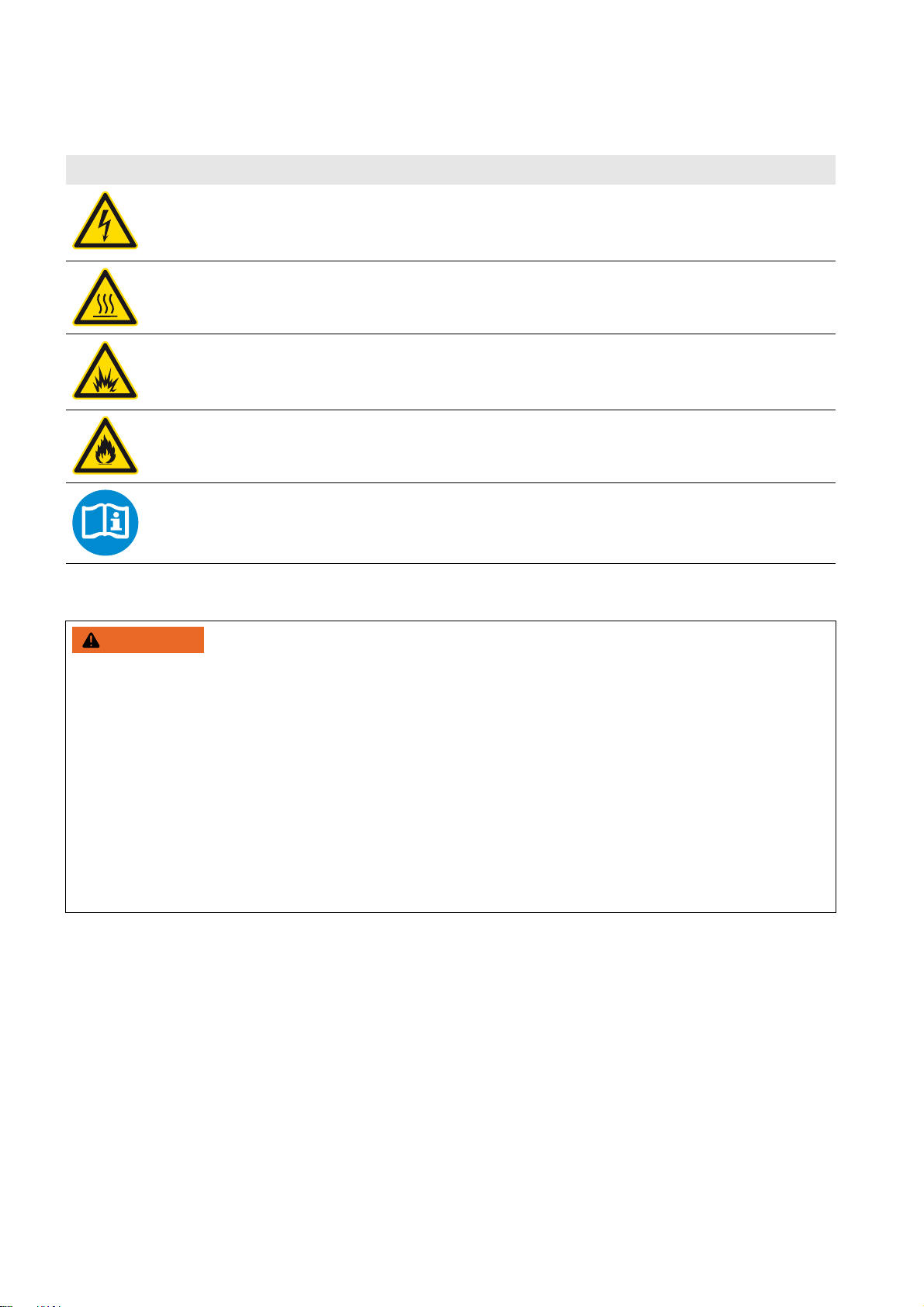
Symbol Description
Warning regarding dangerous voltage
The product works with high voltages. All work on the product must only be performed as described in
the documentation of the product.
Beware of hot surface
The product can become hot during operation. Do not touch the product during operation.
Electric arc hazards
The product has large electrical potential differences between its conductors. Arc flashes can occur
through air when high-voltage current flows. Do not work on the product during operation.
Risk of Fire
Improper installation of the product may cause a fire.
Observe the operating instructions
Read the documentation of the product before working on it. Follow all safety precautions and instructions
as described in the documentation.
General Warnings
General Warnings
All electrical installations must be made in accordance with the local and National Electrical Code
or the Canadian Electrical Code
provincial, federal or national laws, regulation or codes applicable to the installation and use of the product, including
without limitation applicable electrical safety codes. All installations must conform with the laws, regulations, codes and
standards applicable in the jurisdiction of installation. SMA assumes no responsibility for the compliance or
noncompliance with such laws or codes in connection with the installation of the product.
Before installing or using the product, read all of the instructions, cautions, and warnings in this manual.
Before connecting the product to the electrical utility grid, contact the local utility company. This connection must be
made only by qualified personnel.
Wiring of the product must be made by qualified personnel only.
®
CSA C22.1. This document does not and is not intended to replace any local, state,
®
ANSI/NFPA 70
4 SCCP-US-IA-US_en-41 Installation Manual
Page 5

SMA America, LLC Table of Contents
Table of Contents
1 Information on this Document. . . . . . . . . . . . . . . . . . . . . . . . . . . . . . . . . . . . . . . . . . . . . . . . . . . . . 9
1.1 Validity . . . . . . . . . . . . . . . . . . . . . . . . . . . . . . . . . . . . . . . . . . . . . . . . . . . . . . . . . . . . . . . . . . . . . . . . . . . . . . 9
1.2 Target Group . . . . . . . . . . . . . . . . . . . . . . . . . . . . . . . . . . . . . . . . . . . . . . . . . . . . . . . . . . . . . . . . . . . . . . . . . 9
1.3 Additional Information . . . . . . . . . . . . . . . . . . . . . . . . . . . . . . . . . . . . . . . . . . . . . . . . . . . . . . . . . . . . . . . . . . 9
1.4 Symbols . . . . . . . . . . . . . . . . . . . . . . . . . . . . . . . . . . . . . . . . . . . . . . . . . . . . . . . . . . . . . . . . . . . . . . . . . . . . . 9
1.5 Nomenclature. . . . . . . . . . . . . . . . . . . . . . . . . . . . . . . . . . . . . . . . . . . . . . . . . . . . . . . . . . . . . . . . . . . . . . . . 10
1.6 Abbreviations . . . . . . . . . . . . . . . . . . . . . . . . . . . . . . . . . . . . . . . . . . . . . . . . . . . . . . . . . . . . . . . . . . . . . . . . 10
2 Safety . . . . . . . . . . . . . . . . . . . . . . . . . . . . . . . . . . . . . . . . . . . . . . . . . . . . . . . . . . . . . . . . . . . . . . . 11
2.1 Intended Use . . . . . . . . . . . . . . . . . . . . . . . . . . . . . . . . . . . . . . . . . . . . . . . . . . . . . . . . . . . . . . . . . . . . . . . . 11
2.2 Safety Precautions . . . . . . . . . . . . . . . . . . . . . . . . . . . . . . . . . . . . . . . . . . . . . . . . . . . . . . . . . . . . . . . . . . . . 13
2.3 Personal Protective Equipment . . . . . . . . . . . . . . . . . . . . . . . . . . . . . . . . . . . . . . . . . . . . . . . . . . . . . . . . . . . 15
2.4 Symbols on the Sunny Central Inverter. . . . . . . . . . . . . . . . . . . . . . . . . . . . . . . . . . . . . . . . . . . . . . . . . . . . . 16
2.5 Labels on the Sunny Central Inverter . . . . . . . . . . . . . . . . . . . . . . . . . . . . . . . . . . . . . . . . . . . . . . . . . . . . . . 17
2.5.1 Inverter without Integrated DC Switch . . . . . . . . . . . . . . . . . . . . . . . . . . . . . . . . . . . . . . . . . . . . . . . . . . . . . . . .17
2.5.2 Inverter with Integrated DC Switch . . . . . . . . . . . . . . . . . . . . . . . . . . . . . . . . . . . . . . . . . . . . . . . . . . . . . . . . . .19
3 Product Description . . . . . . . . . . . . . . . . . . . . . . . . . . . . . . . . . . . . . . . . . . . . . . . . . . . . . . . . . . . . 21
3.1 Plant Overview . . . . . . . . . . . . . . . . . . . . . . . . . . . . . . . . . . . . . . . . . . . . . . . . . . . . . . . . . . . . . . . . . . . . . . . 21
3.2 Design of the Sunny Central Inverter . . . . . . . . . . . . . . . . . . . . . . . . . . . . . . . . . . . . . . . . . . . . . . . . . . . . . . 23
3.3 Integrated AC Disconnect. . . . . . . . . . . . . . . . . . . . . . . . . . . . . . . . . . . . . . . . . . . . . . . . . . . . . . . . . . . . . . . 23
3.4 Integrated DC Switch . . . . . . . . . . . . . . . . . . . . . . . . . . . . . . . . . . . . . . . . . . . . . . . . . . . . . . . . . . . . . . . . . . 24
3.5 External Fast Stop . . . . . . . . . . . . . . . . . . . . . . . . . . . . . . . . . . . . . . . . . . . . . . . . . . . . . . . . . . . . . . . . . . . . . 25
3.6 Islanding Detection . . . . . . . . . . . . . . . . . . . . . . . . . . . . . . . . . . . . . . . . . . . . . . . . . . . . . . . . . . . . . . . . . . . . 25
3.7 Type Label . . . . . . . . . . . . . . . . . . . . . . . . . . . . . . . . . . . . . . . . . . . . . . . . . . . . . . . . . . . . . . . . . . . . . . . . . . 26
3.8 Schematic Diagram . . . . . . . . . . . . . . . . . . . . . . . . . . . . . . . . . . . . . . . . . . . . . . . . . . . . . . . . . . . . . . . . . . . 26
4 Scope of Delivery. . . . . . . . . . . . . . . . . . . . . . . . . . . . . . . . . . . . . . . . . . . . . . . . . . . . . . . . . . . . . . 27
5 Storage . . . . . . . . . . . . . . . . . . . . . . . . . . . . . . . . . . . . . . . . . . . . . . . . . . . . . . . . . . . . . . . . . . . . . . 28
6 Preparation for Installation. . . . . . . . . . . . . . . . . . . . . . . . . . . . . . . . . . . . . . . . . . . . . . . . . . . . . . 29
6.1 Dimensions of the Inverter. . . . . . . . . . . . . . . . . . . . . . . . . . . . . . . . . . . . . . . . . . . . . . . . . . . . . . . . . . . . . . . 29
6.1.1 Dimensions for Outdoor and Indoor Installation . . . . . . . . . . . . . . . . . . . . . . . . . . . . . . . . . . . . . . . . . . . . . . . .29
6.1.2 Dimensions of the Connection Area . . . . . . . . . . . . . . . . . . . . . . . . . . . . . . . . . . . . . . . . . . . . . . . . . . . . . . . . .31
6.2 Requirements for the Mounting Location . . . . . . . . . . . . . . . . . . . . . . . . . . . . . . . . . . . . . . . . . . . . . . . . . . . 33
6.2.1 Ambient Conditions . . . . . . . . . . . . . . . . . . . . . . . . . . . . . . . . . . . . . . . . . . . . . . . . . . . . . . . . . . . . . . . . . . . . . .33
6.2.2 Supply Air and Exhaust Air . . . . . . . . . . . . . . . . . . . . . . . . . . . . . . . . . . . . . . . . . . . . . . . . . . . . . . . . . . . . . . . .33
6.2.3 Minimum Clearances for Outdoor Installation. . . . . . . . . . . . . . . . . . . . . . . . . . . . . . . . . . . . . . . . . . . . . . . . . .35
6.2.4 Minimum Clearances for Installation in Electrical Equipment Rooms. . . . . . . . . . . . . . . . . . . . . . . . . . . . . . . . .38
6.2.5 Requirements for the Cable Routing between MV Transformer and Inverter. . . . . . . . . . . . . . . . . . . . . . . . . . .39
6.3 Preparation for Installation on a Foundation . . . . . . . . . . . . . . . . . . . . . . . . . . . . . . . . . . . . . . . . . . . . . . . . 41
6.3.1 Requirement for Foundation and Cable Arrangement. . . . . . . . . . . . . . . . . . . . . . . . . . . . . . . . . . . . . . . . . . . .41
6.3.2 Position of the Mounting Holes on the Inverter . . . . . . . . . . . . . . . . . . . . . . . . . . . . . . . . . . . . . . . . . . . . . . . . .42
6.3.3 Drilling Mounting Holes in the Foundation . . . . . . . . . . . . . . . . . . . . . . . . . . . . . . . . . . . . . . . . . . . . . . . . . . . .42
7 Transporting the Inverter. . . . . . . . . . . . . . . . . . . . . . . . . . . . . . . . . . . . . . . . . . . . . . . . . . . . . . . . 43
7.1 Safety Precautions for Transport . . . . . . . . . . . . . . . . . . . . . . . . . . . . . . . . . . . . . . . . . . . . . . . . . . . . . . . . . . 43
Installation Manual SCCP-US-IA-US_en-41 5
Page 6

Table of Contents SMA America, LLC
7.2 Center of Gravity of the Inverter . . . . . . . . . . . . . . . . . . . . . . . . . . . . . . . . . . . . . . . . . . . . . . . . . . . . . . . . . 43
7.3 Mounting the Rear Kick Plates for Installation in Electrical Equipment Rooms . . . . . . . . . . . . . . . . . . . . . . . 44
7.4 Transporting the Inverter Using a Crane Fork . . . . . . . . . . . . . . . . . . . . . . . . . . . . . . . . . . . . . . . . . . . . . . . 44
7.5 Transporting the Inverter Using a Forklift Truck . . . . . . . . . . . . . . . . . . . . . . . . . . . . . . . . . . . . . . . . . . . . . . 45
7.6 Transporting the Inverter Using a Pallet Truck . . . . . . . . . . . . . . . . . . . . . . . . . . . . . . . . . . . . . . . . . . . . . . . 46
7.7 Transporting the Inverter Using a Crane . . . . . . . . . . . . . . . . . . . . . . . . . . . . . . . . . . . . . . . . . . . . . . . . . . . 46
7.7.1 Removing the Roof of the Inverter . . . . . . . . . . . . . . . . . . . . . . . . . . . . . . . . . . . . . . . . . . . . . . . . . . . . . . . . . . .46
7.7.2 Transporting the Inverter . . . . . . . . . . . . . . . . . . . . . . . . . . . . . . . . . . . . . . . . . . . . . . . . . . . . . . . . . . . . . . . . . .49
7.7.3 Mounting the Roof of the Inverter . . . . . . . . . . . . . . . . . . . . . . . . . . . . . . . . . . . . . . . . . . . . . . . . . . . . . . . . . . .50
8 Installation of the Inverter . . . . . . . . . . . . . . . . . . . . . . . . . . . . . . . . . . . . . . . . . . . . . . . . . . . . . . .53
8.1 Installing the Inverter . . . . . . . . . . . . . . . . . . . . . . . . . . . . . . . . . . . . . . . . . . . . . . . . . . . . . . . . . . . . . . . . . . 53
8.1.1 Installing the Inverter on a Foundation. . . . . . . . . . . . . . . . . . . . . . . . . . . . . . . . . . . . . . . . . . . . . . . . . . . . . . . .53
8.2 Removing the Connection Area Panels . . . . . . . . . . . . . . . . . . . . . . . . . . . . . . . . . . . . . . . . . . . . . . . . . . . . 53
8.3 Mounting the Ventilation Plate . . . . . . . . . . . . . . . . . . . . . . . . . . . . . . . . . . . . . . . . . . . . . . . . . . . . . . . . . . . 54
8.4 Mounting the Base Braces . . . . . . . . . . . . . . . . . . . . . . . . . . . . . . . . . . . . . . . . . . . . . . . . . . . . . . . . . . . . . . 55
9 Grounding Connection . . . . . . . . . . . . . . . . . . . . . . . . . . . . . . . . . . . . . . . . . . . . . . . . . . . . . . . . . .56
9.1 Requirements for the Cables and Cable Connection . . . . . . . . . . . . . . . . . . . . . . . . . . . . . . . . . . . . . . . . . . 56
9.1.1 Cable Requirements for the Grounding Connection . . . . . . . . . . . . . . . . . . . . . . . . . . . . . . . . . . . . . . . . . . . . .56
9.1.2 Requirements for the Cable Connection with Terminal Lugs . . . . . . . . . . . . . . . . . . . . . . . . . . . . . . . . . . . . . . .56
9.2 Grounding Connection Overview . . . . . . . . . . . . . . . . . . . . . . . . . . . . . . . . . . . . . . . . . . . . . . . . . . . . . . . . 57
9.3 Connecting the Grounding Cables with Terminal Lugs . . . . . . . . . . . . . . . . . . . . . . . . . . . . . . . . . . . . . . . . 57
10 DC Connection. . . . . . . . . . . . . . . . . . . . . . . . . . . . . . . . . . . . . . . . . . . . . . . . . . . . . . . . . . . . . . . . .59
10.1 Safety Precautions for the DC Connection. . . . . . . . . . . . . . . . . . . . . . . . . . . . . . . . . . . . . . . . . . . . . . . . . . 59
10.2 Requirements for the Cables and Cable Connection. . . . . . . . . . . . . . . . . . . . . . . . . . . . . . . . . . . . . . . . . . 60
10.2.1 Cable Requirements for the DC Connection . . . . . . . . . . . . . . . . . . . . . . . . . . . . . . . . . . . . . . . . . . . . . . . . . . .60
10.2.2 Requirements for the Cable Connection with Terminal Lugs . . . . . . . . . . . . . . . . . . . . . . . . . . . . . . . . . . . . . . .60
10.3 Overview of the DC Connection for the Option DC Fuse . . . . . . . . . . . . . . . . . . . . . . . . . . . . . . . . . . . . . . 61
10.3.1 DC Connection with Negative Grounding . . . . . . . . . . . . . . . . . . . . . . . . . . . . . . . . . . . . . . . . . . . . . . . . . . . .61
10.3.2 DC Connection with Positive Grounding . . . . . . . . . . . . . . . . . . . . . . . . . . . . . . . . . . . . . . . . . . . . . . . . . . . . . .62
10.3.3 DC Connection without Grounding . . . . . . . . . . . . . . . . . . . . . . . . . . . . . . . . . . . . . . . . . . . . . . . . . . . . . . . . . .63
10.4 Overview of the DC Connection for the Optional DC Busbar . . . . . . . . . . . . . . . . . . . . . . . . . . . . . . . . . . . 65
10.4.1 DC Connection with Negative Grounding . . . . . . . . . . . . . . . . . . . . . . . . . . . . . . . . . . . . . . . . . . . . . . . . . . . .65
10.4.2 DC Connection with Positive Grounding . . . . . . . . . . . . . . . . . . . . . . . . . . . . . . . . . . . . . . . . . . . . . . . . . . . . . .66
10.4.3 DC Connection without Grounding . . . . . . . . . . . . . . . . . . . . . . . . . . . . . . . . . . . . . . . . . . . . . . . . . . . . . . . . . .67
10.5 Connecting the DC Cables . . . . . . . . . . . . . . . . . . . . . . . . . . . . . . . . . . . . . . . . . . . . . . . . . . . . . . . . . . . . . 68
11 AC Connection. . . . . . . . . . . . . . . . . . . . . . . . . . . . . . . . . . . . . . . . . . . . . . . . . . . . . . . . . . . . . . . . .71
11.1 Safety Precautions for the AC Connection . . . . . . . . . . . . . . . . . . . . . . . . . . . . . . . . . . . . . . . . . . . . . . . . . . 71
11.2 Requirements for the Cables and Cable Connection . . . . . . . . . . . . . . . . . . . . . . . . . . . . . . . . . . . . . . . . . . 72
11.2.1 Cable Requirements for the AC Connection . . . . . . . . . . . . . . . . . . . . . . . . . . . . . . . . . . . . . . . . . . . . . . . . . . .72
11.2.2 Requirements for the Cable Connection with Terminal Lug . . . . . . . . . . . . . . . . . . . . . . . . . . . . . . . . . . . . . . . .72
11.3 Overview of the AC Connection . . . . . . . . . . . . . . . . . . . . . . . . . . . . . . . . . . . . . . . . . . . . . . . . . . . . . . . . . 73
11.4 Connecting the AC Cables . . . . . . . . . . . . . . . . . . . . . . . . . . . . . . . . . . . . . . . . . . . . . . . . . . . . . . . . . . . . . 73
12 Cable Connection of External Devices in the Interface Cabinet . . . . . . . . . . . . . . . . . . . . . . . . .76
12.1 Connection Area . . . . . . . . . . . . . . . . . . . . . . . . . . . . . . . . . . . . . . . . . . . . . . . . . . . . . . . . . . . . . . . . . . . . . 76
6 SCCP-US-IA-US_en-41 Installation Manual
Page 7

SMA America, LLC Table of Contents
12.1.1 Inverter Without Integrated DC Switch . . . . . . . . . . . . . . . . . . . . . . . . . . . . . . . . . . . . . . . . . . . . . . . . . . . . . . .76
12.1.2 Inverter With Integrated DC Switch. . . . . . . . . . . . . . . . . . . . . . . . . . . . . . . . . . . . . . . . . . . . . . . . . . . . . . . . . .77
12.2 Cable Requirements . . . . . . . . . . . . . . . . . . . . . . . . . . . . . . . . . . . . . . . . . . . . . . . . . . . . . . . . . . . . . . . . . . . 78
12.3 Switching off the Circuit Breaker. . . . . . . . . . . . . . . . . . . . . . . . . . . . . . . . . . . . . . . . . . . . . . . . . . . . . . . . . . 78
12.4 Inserting the Cables into the Interface Cabinet. . . . . . . . . . . . . . . . . . . . . . . . . . . . . . . . . . . . . . . . . . . . . . . 79
12.5 Connecting the Remote Shutdown . . . . . . . . . . . . . . . . . . . . . . . . . . . . . . . . . . . . . . . . . . . . . . . . . . . . . . . . 80
12.6 Connecting the External Setpoint Specification . . . . . . . . . . . . . . . . . . . . . . . . . . . . . . . . . . . . . . . . . . . . . . 80
12.7 Connecting the Transformer Protection. . . . . . . . . . . . . . . . . . . . . . . . . . . . . . . . . . . . . . . . . . . . . . . . . . . . . 81
12.8 Connecting the External Voltage Supply (Optional) . . . . . . . . . . . . . . . . . . . . . . . . . . . . . . . . . . . . . . . . . . 82
12.9 Insulation Monitoring . . . . . . . . . . . . . . . . . . . . . . . . . . . . . . . . . . . . . . . . . . . . . . . . . . . . . . . . . . . . . . . . . . 82
12.10 Connecting the External Fast Stop . . . . . . . . . . . . . . . . . . . . . . . . . . . . . . . . . . . . . . . . . . . . . . . . . . . . . . . 83
12.11 External AC Power Contactor Monitoring . . . . . . . . . . . . . . . . . . . . . . . . . . . . . . . . . . . . . . . . . . . . . . . . . 83
13 Installing the DC Fuses. . . . . . . . . . . . . . . . . . . . . . . . . . . . . . . . . . . . . . . . . . . . . . . . . . . . . . . . . . 84
13.1 Units without Integrated DC Switch . . . . . . . . . . . . . . . . . . . . . . . . . . . . . . . . . . . . . . . . . . . . . . . . . . . . . . . 84
13.2 Units with Integrated DC Switch . . . . . . . . . . . . . . . . . . . . . . . . . . . . . . . . . . . . . . . . . . . . . . . . . . . . . . . . . . 84
14 Disconnecting the Inverter. . . . . . . . . . . . . . . . . . . . . . . . . . . . . . . . . . . . . . . . . . . . . . . . . . . . . . . 86
15 Setting up a Plant Network. . . . . . . . . . . . . . . . . . . . . . . . . . . . . . . . . . . . . . . . . . . . . . . . . . . . . . 90
15.1 Setting up a Plant Network with Copper Cables . . . . . . . . . . . . . . . . . . . . . . . . . . . . . . . . . . . . . . . . . . . . . 90
15.2 Setting up a Plant Network with Optical Fiber . . . . . . . . . . . . . . . . . . . . . . . . . . . . . . . . . . . . . . . . . . . . . . . 90
15.3 Connecting the Inverter via the Service Interface . . . . . . . . . . . . . . . . . . . . . . . . . . . . . . . . . . . . . . . . . . . . . 91
16 Commissioning . . . . . . . . . . . . . . . . . . . . . . . . . . . . . . . . . . . . . . . . . . . . . . . . . . . . . . . . . . . . . . . . 92
16.1 Commissioning the Inverter. . . . . . . . . . . . . . . . . . . . . . . . . . . . . . . . . . . . . . . . . . . . . . . . . . . . . . . . . . . . . . 92
16.2 Checking the Inverter Cabling . . . . . . . . . . . . . . . . . . . . . . . . . . . . . . . . . . . . . . . . . . . . . . . . . . . . . . . . . . . 93
16.3 Mounting the Protective Covers . . . . . . . . . . . . . . . . . . . . . . . . . . . . . . . . . . . . . . . . . . . . . . . . . . . . . . . . . . 93
16.4 Checking the Voltages on the Inverter . . . . . . . . . . . . . . . . . . . . . . . . . . . . . . . . . . . . . . . . . . . . . . . . . . . . . 94
16.4.1 Checking the DC Voltages. . . . . . . . . . . . . . . . . . . . . . . . . . . . . . . . . . . . . . . . . . . . . . . . . . . . . . . . . . . . . . . . .94
16.4.2 Checking the AC Line Voltage. . . . . . . . . . . . . . . . . . . . . . . . . . . . . . . . . . . . . . . . . . . . . . . . . . . . . . . . . . . . . .94
16.4.3 Checking the External AC Power Supply Voltage. . . . . . . . . . . . . . . . . . . . . . . . . . . . . . . . . . . . . . . . . . . . . . .94
16.5 Switching the Voltage Supply On. . . . . . . . . . . . . . . . . . . . . . . . . . . . . . . . . . . . . . . . . . . . . . . . . . . . . . . . . 95
16.6 Switching the AC Disconnect On . . . . . . . . . . . . . . . . . . . . . . . . . . . . . . . . . . . . . . . . . . . . . . . . . . . . . . . . . 96
16.7 Mount the Panels . . . . . . . . . . . . . . . . . . . . . . . . . . . . . . . . . . . . . . . . . . . . . . . . . . . . . . . . . . . . . . . . . . . . . 96
16.8 Switch the Inverter On . . . . . . . . . . . . . . . . . . . . . . . . . . . . . . . . . . . . . . . . . . . . . . . . . . . . . . . . . . . . . . . . . 97
17 Technical Data . . . . . . . . . . . . . . . . . . . . . . . . . . . . . . . . . . . . . . . . . . . . . . . . . . . . . . . . . . . . . . . . 98
17.1 Measurement Accuracy . . . . . . . . . . . . . . . . . . . . . . . . . . . . . . . . . . . . . . . . . . . . . . . . . . . . . . . . . . . . . . . . 98
17.2 Sunny Central 500CP-US/CA . . . . . . . . . . . . . . . . . . . . . . . . . . . . . . . . . . . . . . . . . . . . . . . . . . . . . . . . . . . 98
17.3 Sunny Central 500CP-US/CA 600V . . . . . . . . . . . . . . . . . . . . . . . . . . . . . . . . . . . . . . . . . . . . . . . . . . . . . . 99
17.4 Sunny Central 630CP-US/CA . . . . . . . . . . . . . . . . . . . . . . . . . . . . . . . . . . . . . . . . . . . . . . . . . . . . . . . . . . 100
17.5 Sunny Central 720CP-US/CA . . . . . . . . . . . . . . . . . . . . . . . . . . . . . . . . . . . . . . . . . . . . . . . . . . . . . . . . . . 101
17.6 Sunny Central 750CP-US/CA . . . . . . . . . . . . . . . . . . . . . . . . . . . . . . . . . . . . . . . . . . . . . . . . . . . . . . . . . . 102
17.7 Sunny Central 800CP-US/CA . . . . . . . . . . . . . . . . . . . . . . . . . . . . . . . . . . . . . . . . . . . . . . . . . . . . . . . . . . 104
17.8 Sunny Central 850CP-US/CA . . . . . . . . . . . . . . . . . . . . . . . . . . . . . . . . . . . . . . . . . . . . . . . . . . . . . . . . . . 105
17.9 Sunny Central 900CP-US/CA . . . . . . . . . . . . . . . . . . . . . . . . . . . . . . . . . . . . . . . . . . . . . . . . . . . . . . . . . . 106
17.10 Integrated AC Disconnect . . . . . . . . . . . . . . . . . . . . . . . . . . . . . . . . . . . . . . . . . . . . . . . . . . . . . . . . . . . . . 107
Installation Manual SCCP-US-IA-US_en-41 7
Page 8

Table of Contents SMA America, LLC
18 Contact. . . . . . . . . . . . . . . . . . . . . . . . . . . . . . . . . . . . . . . . . . . . . . . . . . . . . . . . . . . . . . . . . . . . . 108
19 Revision History . . . . . . . . . . . . . . . . . . . . . . . . . . . . . . . . . . . . . . . . . . . . . . . . . . . . . . . . . . . . . 109
8 SCCP-US-IA-US_en-41 Installation Manual
Page 9

SMA America, LLC 1 Information on this Document
1 Information on this Document
This section provides important information on how to use this document and how to work with the Sunny Central inverter.
Among other things, this document specifies the Sunny Central inverters for which this document is valid and the target
group for which it has been written.
1.1 Validity
This document is valid for the following device types:
• Sunny Central 500CP-US/CA (SC 500CP-US-10)
• Sunny Central 500CP-US/CA 600V (SC 500CP-US-10 600V)
• Sunny Central 630CP-US/CA (SC 630CP-US-10)
• Sunny Central 720CP-US/CA (SC 720CP-US-10)
• Sunny Central 750CP-US/CA (SC 750CP-US-10)
• Sunny Central 800CP-US/CA (SC 800CP-US-10)
• Sunny Central 850CP-US/CA (SC 850CP-US-10)
• Sunny Central 900CP-US/CA (SC 900CP-US-10)
The production version is indicated on the type label.
1.2 Target Group
This document is intended for qualified persons. Only qualified persons are allowed to perform the tasks described in this
document.
Qualified persons have received appropriate training and have demonstrated the ability and knowledge to install,
operate, and perform maintenance on the device.
Qualified persons are aware of the obligation to wear Hazard Risk Category 2 personal protective equipment and
always comply with the general safety regulations for dealing with electric voltage.
Qualified persons have been trained in how to deal with the dangers and risks associated with installing electrical
installations as specified in 29 CFR, Chapter XVII, Part 1910 (OSHA), NEC, and NFPA 70E, and possess all the
necessary knowledge for averting danger. There must be written documentation of their training.
1.3 Additional Information
Links to additional information can be found at www.SMA-Solar.com.
Information Document type
Installation requirements for Sunny Central 500CP-US / 500CP-US 600V / 630CP-US /
720CP-US / 750CP-US / 800CP-US / 850CP-US / 900CP-US
Medium-voltage transformers - Important Requirements for Medium-Voltage Transformers
and Transformers for Auxiliary Power Supply for SUNNY CENTRAL CP-US Series Inverters
Sunny Central Communication Controller Technical Information
Technical Information
Technical Information
SC-COM Modbus® Interface (Modbus information including the Zone Monitoring option) Technical description
Q at Night Technical Information
1.4 Symbols
Symbol Explanation
Information that is important for a specific topic or goal, but is not safety-relevant
Installation Manual SCCP-US-IA-US_en-41 9
Page 10

1 Information on this Document SMA America, LLC
Symbol Explanation
☐ Indicates a requirement for meeting a specific goal
☑ Desired result
✖ A problem that could occur
1.5 Nomenclature
Complete designation Designation in this document
SMA America Production, LLC SMA
SMA Solar Technology Canada Inc. SMA
Sunny Central Communication Controller SC-COM
1.6 Abbreviations
Abbreviation Designation Explanation
AC Alternating Current ‒
DC Direct Current ‒
GFDI Ground Fault Detection Interruption ‒
MPP Maximum Power Point ‒
MSL Mean Sea Level ‒
OF Optical Fiber ‒
PC Personal Computer ‒
PE Protective Earth Protective conductor
PV Photovoltaics ‒
10 SCCP-US-IA-US_en-41 Installation Manual
Page 11

SMA America, LLC 2 Safety
:$5 1,1*
2 Safety
In this section, you will find general safety precautions which you must observe whenever working on the Sunny Central
inverter. Pay special attention to these sections to avoid personal injury and property damage.
2.1 Intended Use
The inverter converts the direct current generated in the PV modules into grid-compliant alternating current. An external
MV transformer fitted downstream feeds the alternating current generated into the utility grid.
The inverter is designed for indoor and outdoor installation. The inverter is only licensed for use with a suitable transformer
and providing that the maximum permissible DC input voltage and the permitted ambient conditions are complied with
(see Section17 "Technical Data", page98). The transformer must be designed for voltages that arise during pulsed
mode of the inverter.
The inverter has been evaluated by UL for compliance with UL 1741 / IEEE 1547 requirements at the inverter’s terminals
on the local area side of an interconnection transformer for all IEEE 1547 tests other than for Unintentional Islanding. It
has additionally been evaluated for selected tests for use with UL Recognized Component low-voltage transformers as
noted in the table below:
Test Manufacturer Model Electrical Ratings
Unintentional Islanding Test J. Schneider DLGX
1000F-1016TO1001
Synchronization, Harmonics,
and Open Phase
The inverter has not been evaluated for exporting current into low-voltage electrical power system (EPS) with local loads
present, and must connect to the medium voltage EPS via an externally-provided medium-voltage transformer.
The external medium-voltage transformer shall provide isolated primary and secondary windings rated for the output
voltage and kVA rating of the inverter. The medium-voltage transformer shall be located between the output of the inverter
and the medium-voltage utility power connection.
The Authority Having Jurisdiction (AHJ) must consider the effect of the medium-voltage transformer provided in the field
with respect to electrical ratings, impedance, and the resultant effects on the utility interconnection performance of the
inverter, with respect to the ratings and impedance of the transformer selected.
The inverter has not been evaluated for an installation of multiple inverters connected to one transformer. The Authority
Having Jurisdiction shall determine if any additional evaluation is necessary of such a system.
The inverter can optionally be equipped with an AC power switch for "branch circuit protection". This AC circuit breaker
simultaneously acts as the AC Disconnect in accordance with NEC ANSI/NFPA 70 and CEC. For inverters without an
AC circuit breaker, "branch circuit protection" and an AC Disconnect must be implemented by the installer. Further
information is provided in section 3.1.
The inverter with an integrated AC Disconnect can be optionally ordered with an integrated DC Switch in order to be
able to disconnect the inverter from the PV array. Both devices are designed to be used with a lockout device to secure
the inverter against reconnection during service. If the inverter does not have an integrated DC Switch, an external DC
Disconnect must be installed in accordance with NEC ANSI/NFPA 70 and CEC, in order to be able to disconnect the
inverter from the PV array.
J. Schneider DLGX
1250F-1001TO1001
Primary 289 V
Secondary 480 V, 1,000kVA
Primary 480 V / 1,500A
Secondary 480 V / 1,500A, 1,250kVA
If the unit is not provided with a GFDI or insulation monitoring device, this inverter must be used with an
external GFDI as required by the Article 690 of the National Electrical Code
an external insulation monitoring device according to UL 1741.
Installation Manual SCCP-US-IA-US_en-41 11
®
for the installation location or
Page 12

2 Safety SMA America, LLC
The models SC 850CP-US and SC 900CP-US are only provided with transfer trip functionality to meet unintentional
islanding requirements. An external signal is required from the utility (EPS) to cause the inverter to cease-to-energize the
EPS during an island condition. Both inverters have also been tested for automatic unintentional islanding performance
(IEEE 1547.1 chapter 5.7, "Unintentional Islanding") up to 880 kVA AC power.
The outdoor version of the inverter corresponds to UL 1741 "Type 3R" and can also be operated in rain, sleet, and snow.
The indoor version corresponds to UL 1741 "Type 1" and is only licensed for installation in electrical equipment rooms.
Only persons fulfilling all of the skills for the target group may work on or with the inverter.
Intended use also includes reading the product documentation and observing all safety precautions.
All work on the inverter must be performed using appropriate tools and in compliance with the ESD protection regulations.
NFPA 70B Table 130.7(C)(16) Hazard Risk Category 2 personal protective equipment is to be worn by all persons
working on or with the inverter.
Unauthorized persons may not operate the inverter and must keep at a distance from the inverter.
No reconstruction, modification or installation of additional components may be carried out on the inverter without the
express consent of SMA America, LLC.
The inverter must not be operated with its doors open.
The inverter must not be opened when it is raining or when humidity exceeds 95%.
The inverter must not be operated with any technical defects.
For safety reasons, it is forbidden to modify the product or install components that are not explicitly recommended or
distributed by SMA.
Only use the inverter in accordance with the information provided in the enclosed documentation. Any other application
may cause personal injury or property damage.
The enclosed documentation is an integral part of this product.
• Read and observe the documentation.
• Keep the documentation in a convenient place for future reference.
12 SCCP-US-IA-US_en-41 Installation Manual
Page 13

SMA America, LLC 2 Safety
'$1*(5
2.2 Safety Precautions
This section contains safety precautions that must be observed at all times when working on or with the product. To
prevent personal injury or property damage and to ensure long-term operation of the product, read this section carefully
and follow all safety precautions at all times.
Danger to life from electric shock due to live voltage
High voltages are present in the live components of the inverter. Touching live components results in death or serious
injury due to electric shock.
• When working in a high contact-risk environment, wear Hazard Risk Category 2 personal protective equipment.
• Do not touch live components.
• Follow the instructions precisely.
• Observe all safety messages on the product and in the documentation.
• Observe all safety precautions of the module manufacturer.
• Before any work on the inverter is performed, always disconnect the following components from voltage sources
if live voltage is not absolutely necessary:
– Power line voltage for grid feed-in
– Internal power supply
– DC voltage from the PV array
– Additional external voltages, e.g. control signals of a control room
• Ensure that no disconnected components can be reconnected.
• After disconnecting the inverter from voltage sources, wait at least 15 minutes for the capacitors of the inverter to
discharge completely.
• Always check that no voltage is present in any of the components before working on the inverter.
• Ground and short-circuit the device.
• Cover or shield any adjacent live components.
Danger to life from electric shock due to live DC cables
DC cables connected to PV modules that are exposed to sunlight are live. Touching live components results in death or
serious injury.
• Wear Hazard Risk Category 2 personal protective equipment for all work on the inverter.
• Prior to connecting the DC cables, ensure that the DC cables are voltage-free.
Danger to life from electric shock due to ground fault
If a ground fault has occurred, parts of the plant that are supposedly grounded may in fact be live. Touching incorrectly
grounded components can result in death or very serious injuries from electric shock.
• Ensure that no voltage is present before touching any components of the PV plant.
• Wear Hazard Risk Category 2 personal protective equipment for all work on the inverter.
Danger to life from electric shock when entering the PV field
The insulation monitoring device with GFDI and Advanced Remote GFDI does not provide protection from injury when
GFDI is activated. PV modules grounded by GFDI discharge voltage to ground. When entering the PV field, lethal
electric shocks may occur.
Installation Manual SCCP-US-IA-US_en-41 13
• Before entering the PV field, switch the PV array to insulated operation.
• Ensure that the insulation resistance of the PV array is greater than 1 k Ω .
Page 14

2 Safety SMA America, LLC
:$5 1,1*
'$1*(5
Danger to life from electric shock if the inverter is damaged
Operating a damaged inverter can lead to hazardous situations that result in death or serious injuries due to electric
shock.
• Only use the inverter when it is technically faultless and in an operationally safe state.
• Regularly check the inverter for visible damage.
• Make sure that all external safety equipment is freely accessible at all times.
• Make sure that all safety equipment is in good working order.
• Wear Hazard Risk Category 2 personal protective equipment for all work on the inverter.
Danger to life from electric shock even if the inverter is disconnected on the AC and DC sides
The precharge unit of the option "Q at Night" is also live if the AC contactor and the DC switch are open. Touching live
components of this assembly will result in death or serious injury.
• Do not touch live components.
• Do not remove protective covers.
• Observe the warning messages.
• Wear Hazard Risk Category 2 personal protective equipment.
Danger to life from electric shock when the inverter is not locked
If the inverter is not locked, this means that unauthorized persons have access to components carrying lethal voltages.
Touching live components may result in death or serious injury due to electric shock.
• Always close and lock the inverter.
• Remove the keys from the door locks and from the key switch.
• Keep the keys in a safe place.
• Ensure that unauthorized persons do not have access to the PV plant.
Danger to life due to blocked escape routes
In hazardous situations, blocked escape routes can lead to death or serious injury. Opening the doors of two inverters
located opposite each other blocks the escape route. It is imperative that the escape route is freely accessible at all
times.
• An escape route of at least 3 ft. (915 mm) width must be available at all times. Make sure the minimum passage
width of the route meets local standards.
• Do not place any objects in the escape route path.
• Remove all tripping hazards from the escape routes.
• If two inverters have been installed facing each other, never open the doors of both inverters simultaneously.
Risk of fire due to failure to observe torque specifications on high-voltage bolted connections
Failure to follow the specified torques reduces the ampacity of the live screw connections so that the contact resistances
increase. This can cause components to overheat and catch fire.
• Ensure that high-voltage bolted connections are always executed with the exact torques specified in this document.
• Use suitable tools when working on the device.
• Avoid repeated tightening of high-voltage bolted connections, as this may result in inadmissibly high torques.
14 SCCP-US-IA-US_en-41 Installation Manual
Page 15

SMA America, LLC 2 Safety
&$87,21
/05*$&
Risk of burns due to hot components
Some components of the inverter can become very hot during operation. Touching these components can result in burn
injuries.
• Observe safety messages on the components.
• During operation, do not touch any components marked with such messages.
• After disconnecting the plant from voltage sources, wait until any hot components have cooled down sufficiently.
• Wear personal protective equipment for all work on the inverter.
Damage to the components due to dust or moisture penetration
Dust intrusion or moisture penetration can damage the inverter or impair its functionality.
• Do not open the inverter during rainfall or humidity of more than 95%.
• Only maintain the inverter when the environment is dry and free of dust.
• Do not operate the inverter while the door is open.
• If present, connect the external supply voltage after having set up and installed the inverter.
• Switch on the circuit breaker of the external supply voltage as well as the circuit breakers of the 24 V circuits. This
will activate the heating and interior fans, which will then switch on automatically.
• Mount all panels of the inverter when interrupting the installation process or commissioning.
• Close and lock the inverter.
Damage to electronic components due to electrostatic discharge
Electrostatic discharge can damage or destroy electronic components.
• Observe the ESD safety regulations when working on the device.
• Wear personal protective equipment for all work on the devices.
• Discharge electrostatic charge by touching uncoated, grounded enclosure parts, e.g. at the PE connection on the
doors. Only then is it safe to touch any electronic components.
2.3 Personal Protective Equipment
Always wear the personal protective equipment recommended by SMA America, LLC when working on the inverter. All
clothing should be in accordance with NFPA 70E Section 130.7. Appropriate Insulated gloves for shock protection in
accordance with NFPA 70E Section 130.7(C), rated at least 1000V shall be worn as required.
Any other prescribed protective equipment must also be used. When carrying out work on live parts of the inverter,
protective equipment of at least Hazard Risk Category 2 is required in accordance with NEMA NFPA 70 E, table
130.7(C)(16).
Installation Manual SCCP-US-IA-US_en-41 15
Hazard Risk Category 2 Personal Protective Equipment Required
In accordance with NFPA 70E, an arc flash hazard risk analysis has been performed by SMA, and appropriate Arc
Flash Hazard labels stating the required Personal Protective Equipment (PPE) for exposed, energized interaction with
the equipment, are installed. Hazard Risk Category 2 PPE is the requirement for all routine maintenance, diagnostics,
and commissioning activities as described in the SMA protocols. Areas within the machine also exist that cannot,
under any circumstances, be exposed while energized. These areas are marked accordingly on the machine, and
can only be made accessible after de-energization of the inverter.
For additional information, please contact the SMA Service Line.
Page 16
2 Safety SMA America, LLC
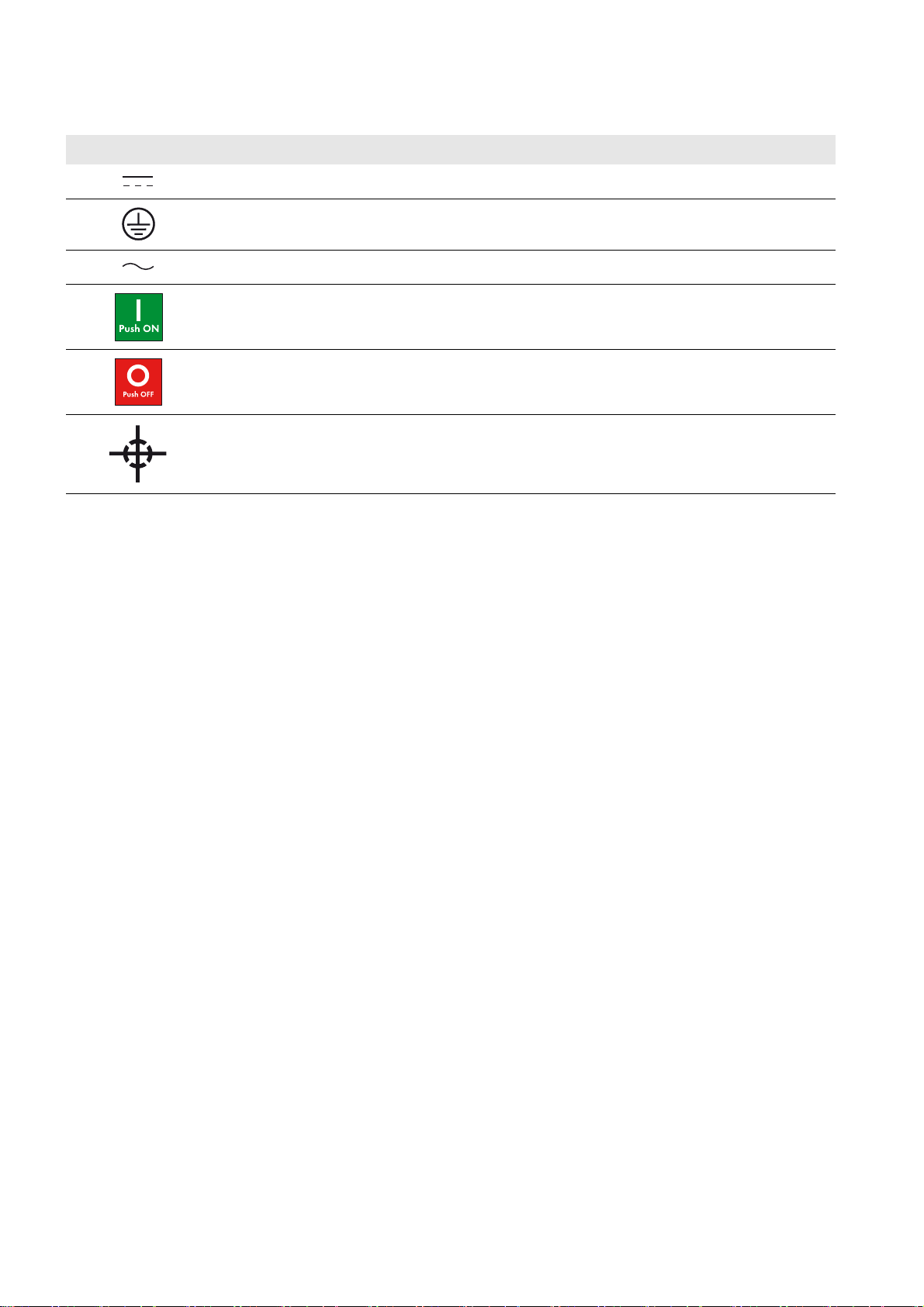
2.4 Symbols on the Sunny Central Inverter
Symbol Explanation
DC current
Earth Ground
AC current
On position of the AC Disconnect
Off position of the AC Disconnect
Center of gravity
16 SCCP-US-IA-US_en-41 Installation Manual
Page 17
SMA America, LLC 2 Safety
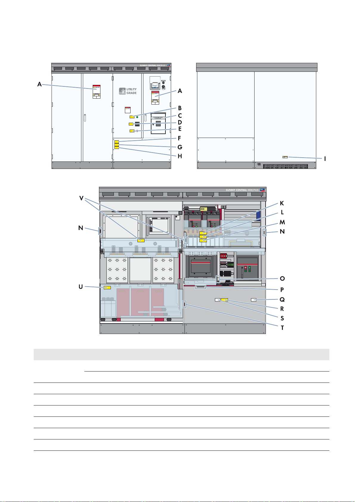
2.5 Labels on the Sunny Central Inverter
This section describes the positions of the labels on the inverter. The warning labels identify potentially hazardous areas
or components. Familiarize yourself with the warning labels and their positions before working on the inverter.
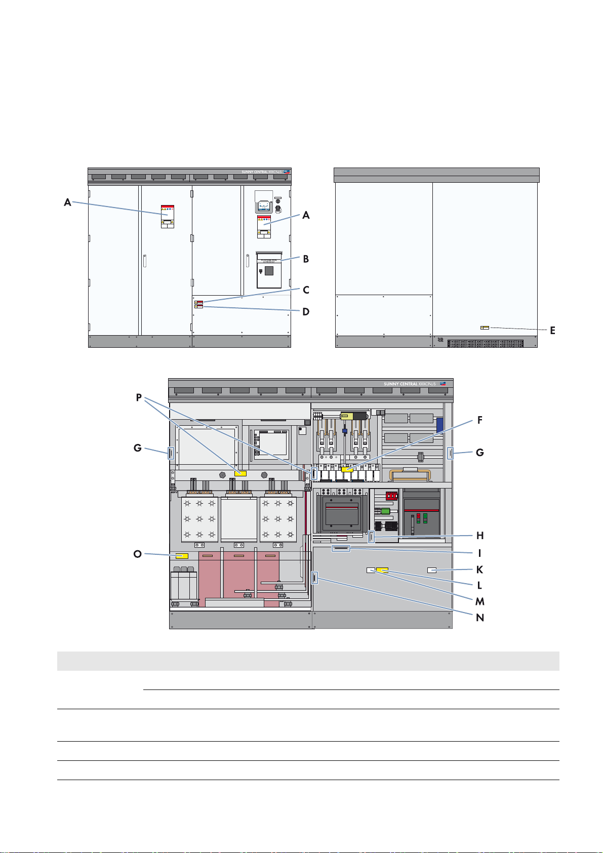
2.5.1 Inverter without Integrated DC Switch
Figure1: Safety messages on the inverter
Position SMA order number Description
A 86-0043464 Warning label general SC-US EN
86-430042 Warning label Arc Flash Hazard Protection
B 86-00480030 Only with order option AC Disconnect: Photovoltaic System AC
Disconnect
C 86-00480020 Warning label Arc Flash
D 86-0043474 Warning label SC-US external transformer EN
Installation Manual SCCP-US-IA-US_en-41 17
Page 18

2 Safety SMA America, LLC
Position SMA order number Description
E 86-004300 Warning label, Burn Hazard, Hot surface
F 86-0043472 Only for order option DC fuses: Warning label SC-US DC fuses
EN/ES
86-0043473 Only for order option DC fuses: Warning label SC-US DC fuses
EN/FR
G ‒ Type label
H ‒ Label control supply voltage
I 86-10867027 For positive grounding: 1,000 V PV‒
86-430045 For positive grounding: 600 V PV‒*
86-10867028 For negative grounding: 1,000 V PV+
86-430044 For negative grounding: 600 V PV+*
K 86-0043462 ABC 60Hz
86-101300.1 ABC 50 Hz
L 86-0043470 Warning label SC-US Conductors, EN-FR
86-0043469 Warning label SC-US Conductors, EN-ES
M 86-0043460 Grounding Electrode Terminal
N 86-10867027 For negative grounding or insulated: 1,000 V PV‒
86-430045 For negative grounding or insulated: 600 V PV‒*
86-10867028 For positive grounding or insulated: 1,000 V PV+
86-430044 For positive grounding or insulated: 600 V PV+*
O 86-108680046 Warning label SC US capacitors C1-C3, C6 optional EN/FR
86-108680047 Warning label SC US capacitors C1-C3, C6 optional EN/ES
P 86-0043476 Warning label, SC US stack capacitors EN/ES
86-0043477 Warning label, SC US stack capacitors EN/FR
* For Sunny Central 500CP-US 600V
Replacing warning labels
Missing or damaged warning labels m ust be replaced. The warning labels can be ordered from SMA using the SMA
order numbers listed above.
18 SCCP-US-IA-US_en-41 Installation Manual
Page 19
SMA America, LLC 2 Safety
2.5.2 Inverter with Integrated DC Switch
Figure2: Safety messages on the inverter
Position SMA order number Description
A 86-0043464 Warning label general SC-US EN
86-430042 Warning label Arc Flash Hazard Protection
B 86-0033325 Label "Closed"
C 86-00480030 Label "Photovoltaic System AC Disconnect"
D 86-101400.1 Label "DC-Switch"
E 86-0033324 Label "Open"
F 86-00480020 Warning label Arc Flash
G 86-0043474 Warning label SC-US external transformer EN
Installation Manual SCCP-US-IA-US_en-41 19
Page 20

2 Safety SMA America, LLC
Position SMA order number Description
H 86-0033326 Warning label Electric Shock due to Live Voltage EN/ES
86-0033327 Warning label Electric Shock due to Live Voltage EN/FR
I 86-004300 Warning label Burn Hazard
K 86-0043472 Only for order option DC fuses: Warning label SC-US DC fuses
EN/ES
86-0043473 Only for order option DC fuses: Warning label SC-US DC fuses
EN/FR
L 86-0033321 Warning label Electric Shock Hazard EN/FR
86-0033322 Warning label Electric Shock Hazard EN/ES
M 86-0033329 Warning label Danger: Do not pull out fuses under load EN/FR
86-0033328 Warning label Danger: Do not pull out fuses under load EN/ES
N‒ Nameplate
O ‒ Label control supply voltage
P 86-10867027 For positive grounding: 1,000 V PV‒
86-430045 For positive grounding: 600 V PV‒*
86-10867028 For negative grounding: 1,000 V PV+
86-430044 For negative grounding: 600 V PV+*
Q 86-0043462 ABC 60Hz
86-101300.1 ABC 50 Hz
R 86-0043470 Warning label SC-US Conductors, EN-FR
86-0043469 Warning label SC-US Conductors, EN-ES
S 86-0043460 Grounding Electrode Terminal
T 86-10867027 For negative grounding or insulated: 1,000 V PV‒
86-430045 For negative grounding or insulated: 600 V PV‒*
86-10867028 For positive grounding or insulated: 1,000 V PV+
86-430044 For positive grounding or insulated: 600 V PV+*
U 86-108680046 Warning label SC US capacitors C1-C3, C6 optional EN/FR
86-108680047 Warning label SC US capacitors C1-C3, C6 optional EN/ES
V 86-0043476 Warning label, SC US stack capacitors EN/ES
86-0043477 Warning label, SC US stack capacitors EN/FR
* For Sunny Central 500CP-US 600V
Replacing warning labels
Missing or damaged warning labels m ust be replaced. The warning labels can be ordered from SMA using the SMA
order numbers listed above.
20 SCCP-US-IA-US_en-41 Installation Manual
Page 21
SMA America, LLC 3 Product Description
3 Product Description
This section will give you an overview of the inverter and its components.
3.1 Plant Overview
The inverter converts the direct current generated in the PV modules into grid-compliant alternating current. An external
MV transformer fitted downstream feeds the alternating current generated into the utility grid.
An AC Disconnect and DC Disconnect must be installed in accordance with NEC ANSI/NFPA 70 and CEC.
The inverter can be optionally ordered with an integrated AC Disconnect and an integrated DC Switch. Both devices are
designed to be used with a lockout device to secure the inverter against reconnection during service. With the AC
Disconnect, the inverter can be disconnected from the utility grid simply and safely. This option does not require an
additional AC Disconnect Unit on the AC side.
With the DC Switch, the inverter can be disconnected from the PV array. If the inverter does not have an integrated DC
Switch, an external DC Disconnect must be installed in accordance with NEC ANSI/NFPA 70 and CEC, in order to be
able to disconnect the inverter from the PV array. This allows you to easily and safely disconnect the inverter as needed.
In some jurisdictions, additional external disconnecting means may be required for servicing of the DC input fuses. SMA
recommends an early review with the AHJ to identify their requirements for the PV System.
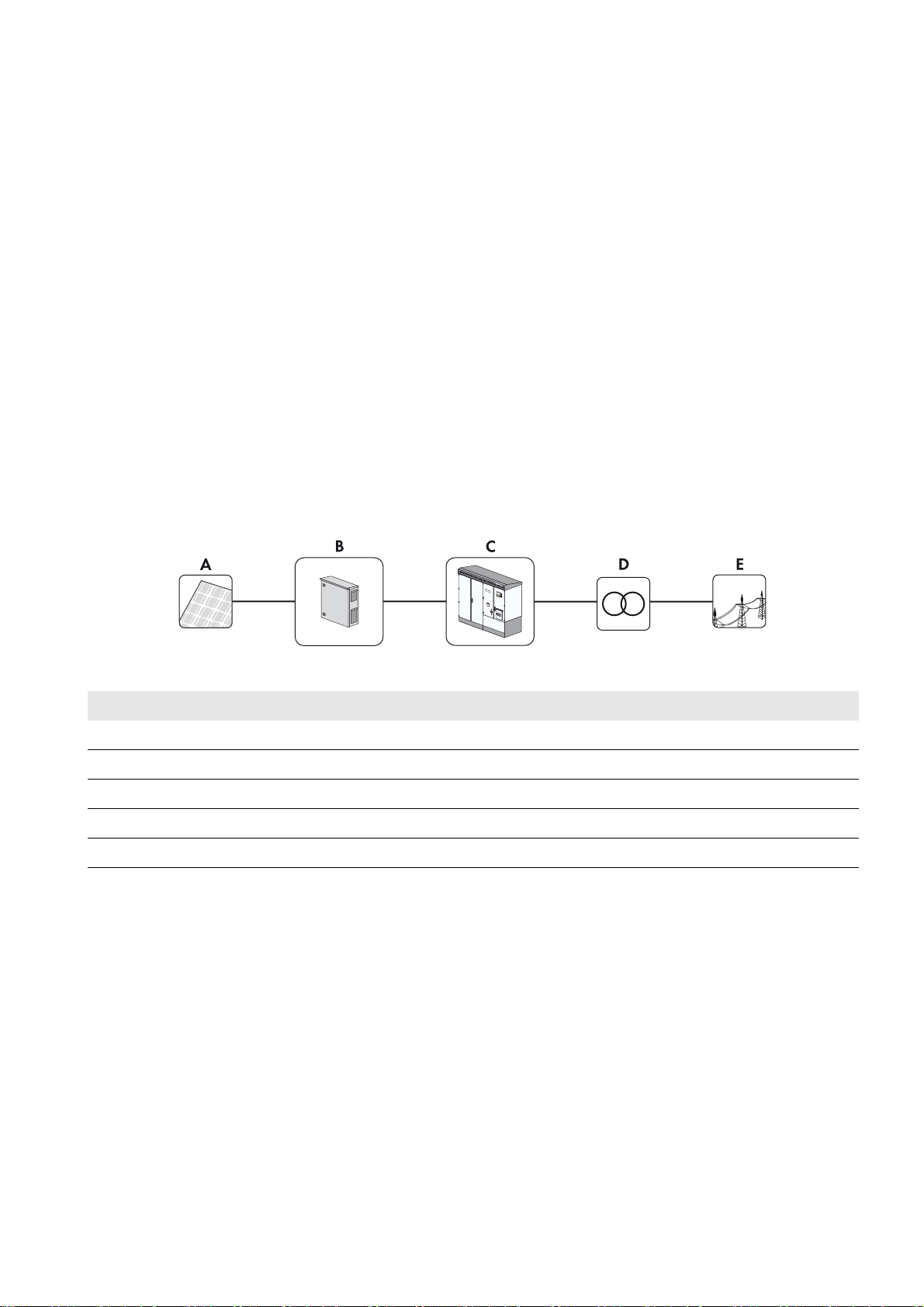
Sunny Central Inverter with Integrated AC Disconnect and Integrated DC Switch
Figure3: Principle of a grid-tie PV plant with a Sunny Central Inverter with integrated AC Disconnect and DC Switch
Position Description
A PV array
B String Combiner Box
C Inverter with integrated AC Disconnect and DC Switch
E External transformer
F Utility grid
Installation Manual SCCP-US-IA-US_en-41 21
Page 22
3 Product Description SMA America, LLC
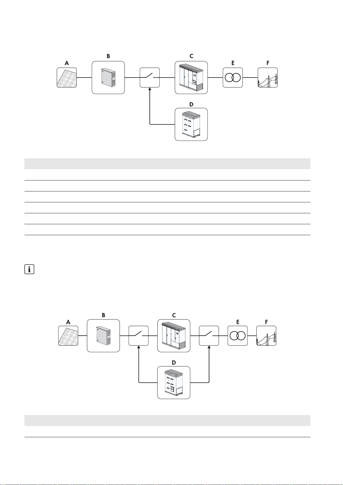
Sunny Central Inverter with Integrated AC Disconnect and External DC Disconnect
Figure4: Principle of a grid-tie PV plant with an external DC Disconnect and a inverter with integrated AC Disconnect
Position Description
A PV array
B String Combiner Box
C Inverter with Integrated AC Disconnect
D DC DisconnectUnit
E External transformer
F Utility grid
Sunny Central Inverter with External AC Disconnect and External DC Disconnect
As an option, the AC circuit breaker can be mounted externally.
Circuit breaker
The unit is provided with a UL listed circuit breaker on the output rated 1,600 A for branch circuit protection. If the
circuit breaker shall be located externally to secure the AC path, you have to use the same type of circuit breaker
(ABB Emax E2B-A with 42kA rated short-circuit current, ABB Emax E2N-A with 65 kA rated short-circuit current or
ABB Emax E2H-A with 85kA rated short-circuit current and 1,600 A continuous current rating each).
Figure5: Principle of a grid-tie PV plant with a Sunny Central inverter and external AC / DC Disconnect Unit
Position Description
A PV modules
22 SCCP-US-IA-US_en-41 Installation Manual
Page 23
SMA America, LLC 3 Product Description
Position Description
B String Combiner Box
C Inverter without integrated AC Disconnect and without integrated DC Switch
D AC / DC DisconnectUnit
E External transformer
F Utility grid
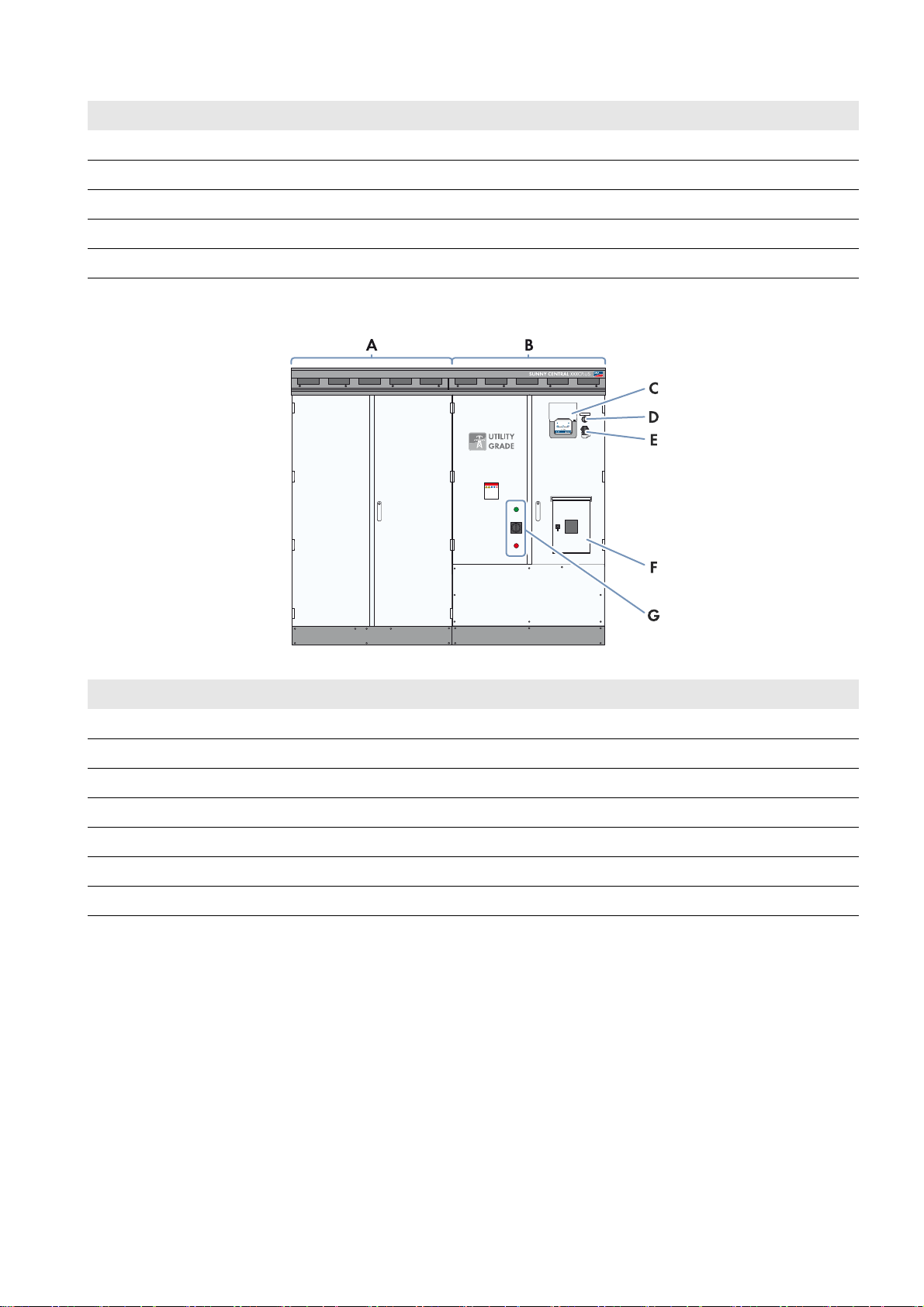
3.2 Design of the Sunny Central Inverter
Figure6: Design of the Sunny Central inverter (example)
Position Description
A Inverter cabinet
B Interface cabinet
CTouch display
DKey switch
EService interface
F Integrated AC Disconnect*
G Integrated DC Switch*
*Optional
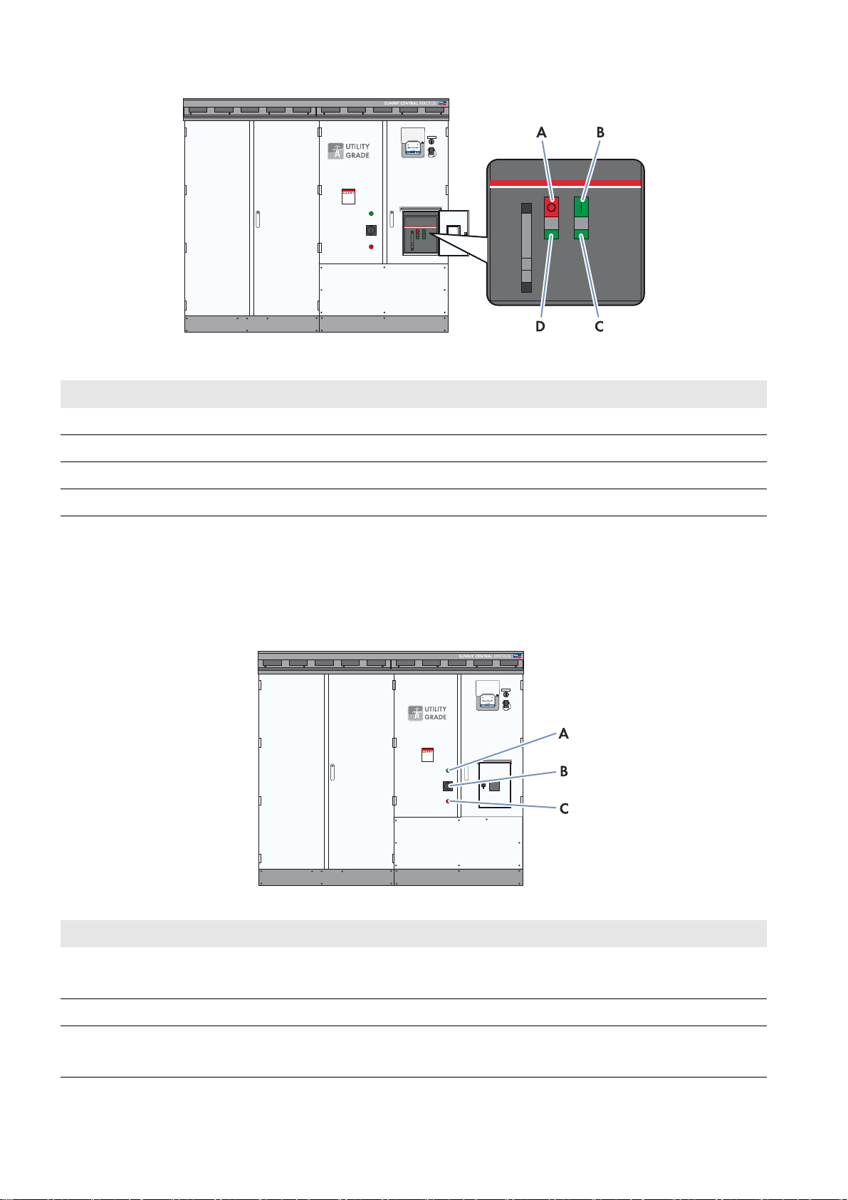
3.3 Integrated AC Disconnect
Depending on the option ordered, the Sunny Central CP-US may be fitted with an integrated AC Disconnect. The
AC Disconnect enables you to disconnect the inverter from the AC grid in the event an emergency and for service and
maintenance work.
Installation Manual SCCP-US-IA-US_en-41 23
Page 24
3 Product Description SMA America, LLC
Figure7: AC Disconnect
Position Description
A OFF button
BON button
C Spring status indicator
D Position indicator
3.4 Integrated DC Switch
Depending on the option ordered, the Sunny Central CP-US inverter may be fitted with an integrated DC Switch. The
DC Switch enables you to disconnect the inverter from the PV array in the event an emergency and for service- and
maintenance work. Despite disconnecting the integrated DC Switch, voltages are still present on the DC fuses and the
inverter busbars. Touching the DC fuses or the busbars will result in death or very serious injuries from electric shock.
Figure8: Integrated DC Switch
Position Description
A Green light repeater
The DC Switch is closed.
B DC Switch (lockable with a lockout device)
C Red light repeater
The DC Switch is open.
24 SCCP-US-IA-US_en-41 Installation Manual
Page 25

SMA America, LLC 3 Product Description
3.5 External Fast Stop
The external fast stop is to be used if the inverter is to be disconnected via an external signal in accordance with IEEE
1547 (e.g. External Islanding Detection). The inverter is delivered with a fast stop input. It is possible to connect an
external switch to this fast stop input. The external fast stop disconnects the inverter from the utility grid within 100 ms.
The options for configuring the external fast stop are displayed in the following table.
Option Description
The external fast stop is
deactivated.
The external fast stop is
operated via an external 24 V
supply.
Tripping the fast stop function
The fast stop function should only be tripped in the event of immediate danger. Tripping the fast stop will not rapidly
discharge the capacitors. If the inverter is to be switched off and correctly shut down via an external signal, use the
input of the remote shutdown function.
The models SC 850CP-US inverter and SC 900CP-US inverter are only provided with transfer trip functionality to meet
unintentional islanding requirements. An external signal is required from the utility (EPS) to utilize this feature.
The terminals of the active fast stop are bridged ex works. The fast stop function is
thus deactivated.
An external latching switch (break contact) is connected to the inverter terminals via
an external 24 V voltage supply. If the external switch is inactive, the switch relay is
energized and the inverter feeds into the grid. If the external switch is activated, the
relay is de-energized and the fast stop is tripped. The inverter is stopped and no
longer feeds energy into the grid.
Voltage ranges for the relay:
24 V to 30 V: The inverter is in operation.
0 V to 4 V: The inverter is not in operation.
3.6 Islanding Detection
Stand-alone grids form when the following conditions occur simultaneously:
• The medium-voltage grid fails.
• The inverter feeds in an amount x of power. There is an electrical load on the same branch of the grid with a load
equal to that of power x.
There are two methods for islanding detection:
• Active Islanding Detection*
• External Islanding Detection
Active Islanding Detection
The inverter detects the formation of stand-alone grids during a grid failure and disconnects the inverter from the utility
grid.
This function is set via the parameter EnaAID and cannot be active at the same time as the "FRT" function.
External Islanding Detection
In the event of a grid failure, the fo rmation of stand-alone grids is detected at the farm level. If a stand-alone grid is formed,
a signal is transmitted to the fast stop input of the inverter.
If the signal appears at the fast stop input of the inverter while the inverter is in the "MPP load operation" operating state,
the inverter switches to the operating state "Shutdown". Once shutdown is complete, the AC contactor and the DC
switching device open automatically and the inverter switches to the operating state "Stop".
For external islanding detection, a suitable cable must be connected to the inverter fast stop input during installation.
* Not with some models of the SC 850CP-US inverter and the SC 900CP-US inverter
Installation Manual SCCP-US-IA-US_en-41 25
Page 26
3 Product Description SMA America, LLC
3.7 Type Label
You can identify the Sunny Central CP-US via the type label. Type labels are attached at the top right on the inside of the
interface cabinet and on the top left side of the inverter cabinet. You will find the following information on the type label:
•Device type
• Serial number
•Production version
• Production date
• Device-specific data
Reading the serial number
You can read the serial number without opening the inverter. The serial number can be found on the inverter on the
top left corner of the roof. You can also read the serial number from the display.
Reading the firmware version
You can read the version number of the firmware of the inverter and the display via the user interface of the SC-COM
or on the display.
Symbols on the Type Label
Symbol Description Explanation
Danger to life due to high
voltages
Risk of burns due to hot surfaces The product can become hot during operation. Avoid contact
Observe the documentation. Observe all documentation that is supplied with the product.
The product operates at high voltages. All work on the product
must be carried out by qualified persons only.
during operation. Allow the product to cool down sufficiently
before carrying out any work. Wear personal protective
equipment such as safety gloves.
Evaluated to the requirements of the Underwriters Laboratories
Standard for Safety for Inverters, Converters, Controllers and
Interconnection System Equipment for Use With Distributed
Energy Resources, UL 1741.
The inverter has been additionally evaluated by Underwriters
Laboratories to CAN/CSA C22.2 No. 107.1-1, "General Use
Power Supplies".
3.8 Schematic Diagram
Schematic diagrams in PDF format contain jump marks. By double clicking a jump mark, the display will change to the
corresponding current path or the referenced place in the equipment list.
SMA recommends using schematic diagrams in PDF format during troubleshooting. The schematic diagrams in PDF
format are available on request. Contact the SMA Service Line.
26 SCCP-US-IA-US_en-41 Installation Manual
Page 27
SMA America, LLC 4 Scope of Delivery
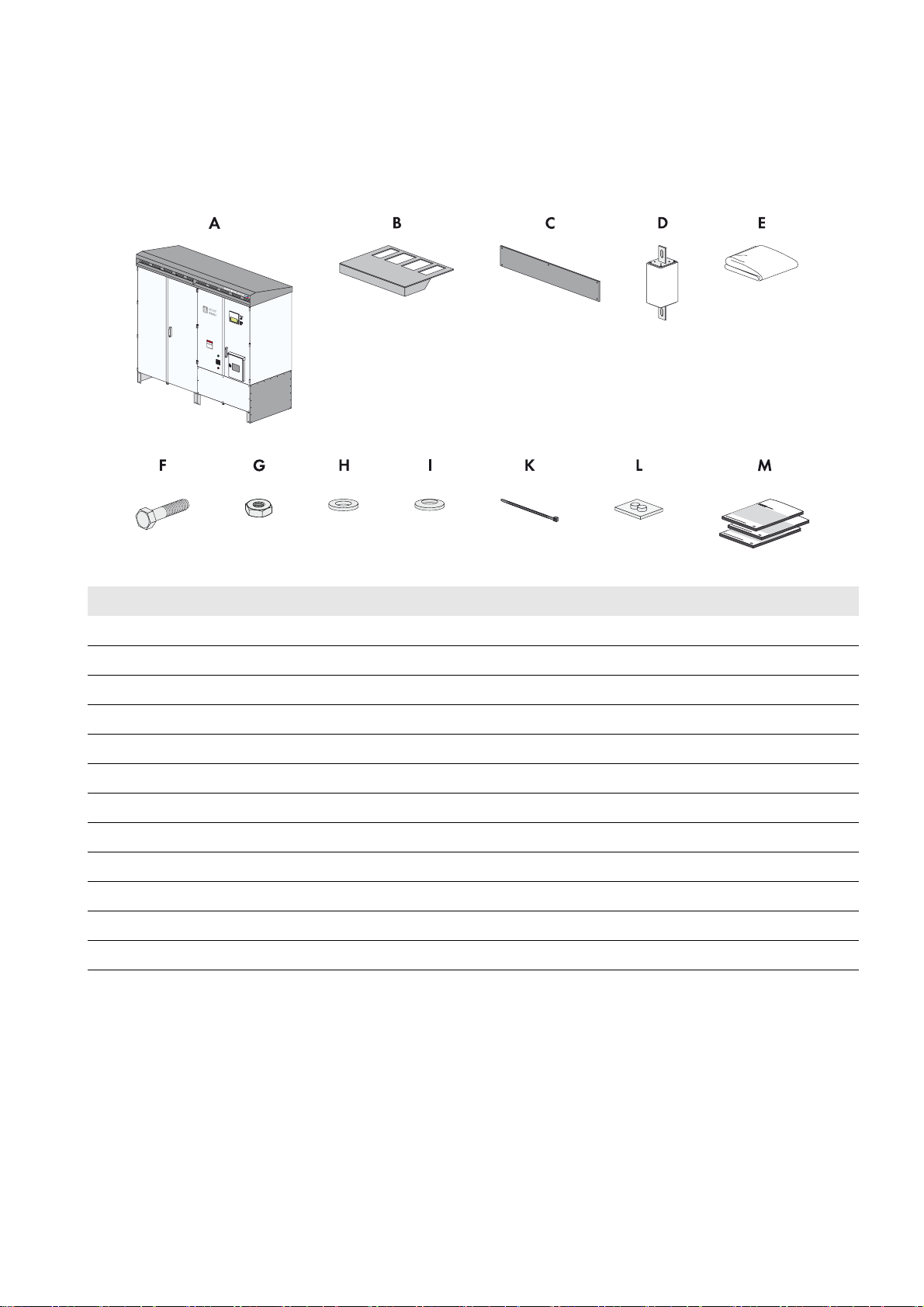
4 Scope of Delivery
Check the scope of delivery for completeness and any externally visible damage. Contact your distributor if the scope of
delivery is incomplete or damaged.
The scope of delivery depends on the order options.
Figure9: Components included in the scope of delivery
Position Number Description
A1Inverter
B 1 Ventilation plate
C4Kick plate
D 6/7/8/9 DC fuse*
E 1 Non-woven abrasive
F 74 Hexagon screw*
G74Hexagon nut*
H 148 Washer*
I148Spring washer*
K 80 Cable tie
L 3 Rubber seal
M 1 each Installation manual, user manual, circuit diagram, commissioning report
*Optional
Installation Manual SCCP-US-IA-US_en-41 27
Page 28

5 Storage SMA America, LLC
/05*$&
/05*$&
5 Storage
This section gives you information on how to store the inverter correctly. Follow the information in this section if the inverter
is not to be mounted immediately on its foundation or base. This will help prevent damage to the inverter.
Damage to the inverter due to moisture penetration
If the inverter is not stored properly, moisture can penetrate the enclosure and cause damage to electronic components.
• Only store the inverter in its closed state.
• Storage for six months or more permissible in dry locations only.
• Store at a temperature between ‒13°F and +140°F ( − 25°C to +60°C).
Damage to the inverter due to uneven building ground
Storing the inverter on an unsuitable building ground could damage the frame construction. Dust and moisture can
penetrate the inverter and damage electronic components.
• The building ground must be suitable for the weight of the inverter of 4,123 lbs. (1,870 kg).
• The unevenness of the building ground must not exceed 0.25%.
Storage in cold temperatures and high humidity
If, when storing the device, you connect the external voltage supply and switch on the circuit breaker of the external
voltage supply as well as the circuit breakers of the 24 V circuits, the heater is activated automatically in the event
of high humidity. As a result, you prevent condensation water from forming. The connection of the external voltage
supply is described in Section 12.8.
28 SCCP-US-IA-US_en-41 Installation Manual
Page 29
SMA America, LLC 6 Preparation for Installation
6 Preparation for Installation
This section describes which preparations you need to perform for the various installation options of the inverter. Read
this section and follow the instructions to perform all the necessary preparations prior to transporting the inverter.
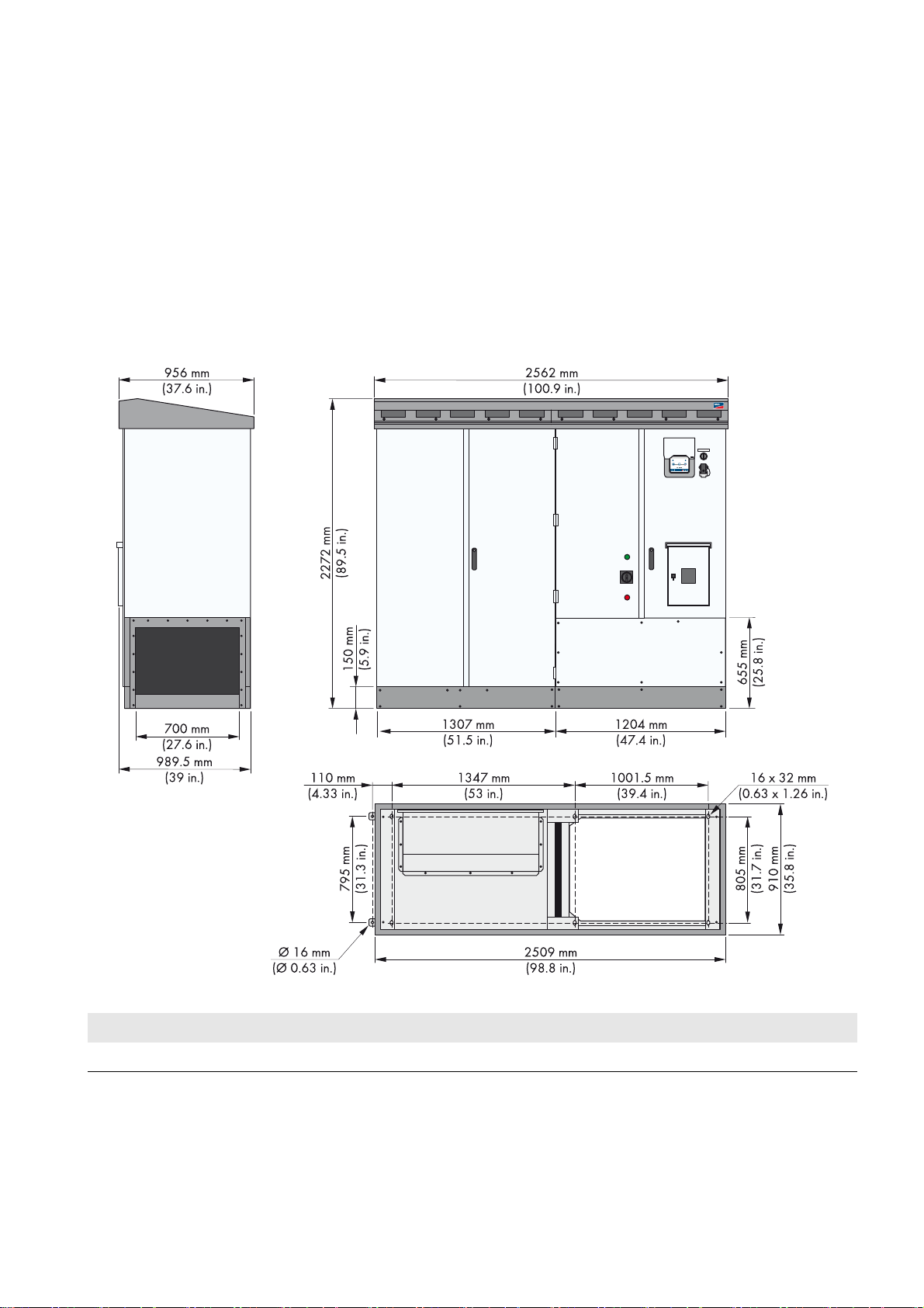
6.1 Dimensions of the Inverter
6.1.1 Dimensions for Outdoor and Indoor Installation
Depending on the order option, the inverter will be delivered with the roof for outdoor installation or without the roof for
indoor installation.
Dimensions with Roof
Figure10: Dimensions with Roof
Width Height Depth Weight
8 ft. 4.87 in. (2,562 mm) 7 ft. 5.45 in. (2,272 mm) 3 ft. 1.64 in. (956 mm) 4,123 lb (1,870 kg)
Installation Manual SCCP-US-IA-US_en-41 29
Page 30
6 Preparation for Installation SMA America, LLC
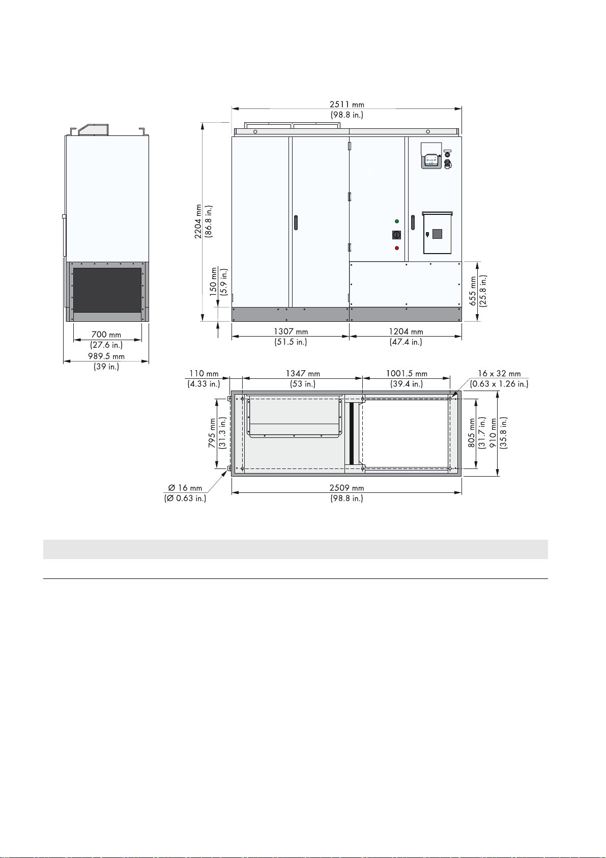
Dimensions without Roof
Figure11: Dimensions without roof
Width Height Depth Weight
8 ft. 2.59 in. (2,511 mm) 7 ft. 2.78 in. (2,204 mm) 2 ft. 11.83 in. (910 mm) 4,045 lb (1,835 kg)
30 SCCP-US-IA-US_en-41 Installation Manual
Page 31

SMA America, LLC 6 Preparation for Installation
6.1.2 Dimensions of the Connection Area
Dimensions of the Connection Area for the Option DC Fuses
Figure12: Dimensions of the connection area for the option DC fuses
Position Description
A Grounding busbar
B For negative grounding: busbar DC-
For positive grounding: busbar DC+
C For positive grounding: busbar DC-
For negative grounding: busbar DC+
D AC busbar: line conductor A
E AC busbar: line conductor B
F AC busbar: line conductor C
Installation Manual SCCP-US-IA-US_en-41 31
Page 32

6 Preparation for Installation SMA America, LLC
Dimensions of the Connection Area for the Option DC Busbar
Figure13: Dimensions of the connection area for the option DC busbar
Position Description
A Grounding busbar
B For negative grounding: busbar DC-
For positive grounding: busbar DC+
C For positive grounding: busbar DC-
For negative grounding: busbar DC+
D AC busbar: line conductor A
E AC busbar: line conductor B
F AC busbar: line conductor C
32 SCCP-US-IA-US_en-41 Installation Manual
Page 33

SMA America, LLC 6 Preparation for Installation
/05*$&
6.2 Requirements for the Mounting Location
This section describes which requirements must be met at the mounting location of the inverter. The conditions specified
here apply equally for each installation option. Observe this section and make sure that the requirements are met prior
to preparing the mounting location for the inverter.
6.2.1 Ambient Conditions
Damage to the inverter due to dust or moisture penetration
Dust intrusion or moisture penetration can damage the inverter or impair the functionality of the inverter.
• Do not open the inverter during rainfall or humidity of more than 95%.
• Only open the inverter when the environment is dry and free of dust.
• Only use rainproof, wet-room suitable conduits that comply with UL 514B for the connection to the switch cabinet.
The following ambient conditions must be maintained under all circumstances to ensure the optimum and safe operation
of the inverter.
☐ The mounting location must be freely accessible at all times.
☐ The ambient temperature must be within the operating temperature range.
☐ For further information on the ambient conditions, (see Section17 "Technical Data", page98).
For further information on the installation, see "Installation requirements for Sunny Central CP-US", which can be
downloaded in the download area at www.SMA-America.com or www.SMA-Solar.com.
6.2.2 Supply Air and Exhaust Air
The innovative OptiCool cooling concept makes it possible to operate inverters at full nominal power at ambient
temperatures of up to +122°F (+50°C).
At temperatures exceeding +122 °F (+50 °C), the inverter continues feeding in but reduces feed-in power to protect the
PV system.
The cooling air is drawn in through the inverter roof and is blown out
again through the slits at the rear of the inverter.
The illustration on the right shows the principle of the air circulation within
the inverter.
The inverter needs 1766 SCFM (3,000 m
inverter draws in through the ventilation grids in the front. The fresh air
must meet the 4S2 classification.
You can install the inverter in a chemically active environment. The
inverter is protected against salt spray in accordance with
EN 60721-3-4 class 4C2. You will find the required air qualities in the
following table.
3
/h) of fresh air, which the
Installation Manual SCCP-US-IA-US_en-41 33
Page 34

6 Preparation for Installation SMA America, LLC
Air quality classification for mechanically active substances
Ambient conditions for stationary application Class 4S2
a) Sand in air [mg/m
b) Dust (suspended matter) [mg/m
c) Dust (precipitation) [mg/m
Installation sites where appropriate measures are taken to keep dust levels to a minimum. x
3
]300
3
]5.0
3
]20
Installation sites where no special measures have been taken to reduce the sand or dust levels and
x
which are not located in the vicinity of sand or dust sources.
Air quality classification for chemically active substances
Ambient conditions for stationary application Class 4C2
Mean value Threshold
a) Sea salt Occurrence of salt spray
b) Sulfur dioxide [mg/m
c) Hydrogen sulfide [mg/m
d) Chlorine [mg/m
e) Hydrogen chloride [mg/m
f) Hydrogen fluoride [mg/m
g) Ammonia [mg/m
h) Ozone [mg/m
i) Nitrogen oxides [mg/m
Installation sites in rural or densely populated areas with little industry and moderate
traffic volume.
3
]0.31.0
3
]0.10.5
3
]0.10.3
3
]0.10.5
3
]0.010.03
3
]1.03.0
3
] 0.05 0.1
3
]0.51.0
x
Installation sites in densely populated areas with industry and high traffic volume. x
34 SCCP-US-IA-US_en-41 Installation Manual
Page 35

SMA America, LLC 6 Preparation for Installation
:$5 1,1*
/05*$&
Exhaust air
The Sunny Central blows the exhaust air out through the openings in the base area of the inverter cabinet. The following
figure shows the dimensions of the exhaust air opening.
Figure 14: Dimensions of the exhaust air opening
6.2.3 Minimum Clearances for Outdoor Installation
Fire hazard due to overheating of cables
Differing cable lengths lead to overheating of the cables. Excessive heat can result in cable fires. Death or serious injury
due to fire can result.
• All line conductors from the inverter to the transformer must be of the same length. However, the cables must not
be longer than 49 ft. (15 m) between connection points.
Damage to the inverter or transformer due to overheating
Inverters or transformers can overheat and be damaged due to the drawing-in of exhaust air from other inverters.
• Install the plant in such a way that the inverter cannot draw in any exhaust air from other devices.
• Follow the supply air and exhaust air requirements (see Section6.2.2 "Supply Air and Exhaust Air", page33)I
Installation Manual SCCP-US-IA-US_en-41 35
Page 36

6 Preparation for Installation SMA America, LLC
Minimum Clearances for One Inverter
Figure15: Minimum clearances for one inverter
Minimum Clearances for Two Inverters with Transformer
Version 1 - Rear to Rear:
Figure16: Minimum Clearances for two inverters with transformer - version 1
Position Description
AInverter 1
BInverter 2
C MV transformer and medium-voltage switchgear
D Cable route between inverter and MV transformer (49 ft. (15 m))
36 SCCP-US-IA-US_en-41 Installation Manual
Page 37

SMA America, LLC 6 Preparation for Installation
Version 2 - Front to Front:
Figure17: Minimum clearances for two inverters with transformer - version 2
Position Description
AInverter 1
BInverter 2
C MV transformer and medium-voltage switchgear
D Cable route between inverter and MV transformer (49 ft. (15 m))
Installation Manual SCCP-US-IA-US_en-41 37
Page 38

6 Preparation for Installation SMA America, LLC
/05*$&
:$5 1,1*
6.2.4 Minimum Clearances for Installation in Electrical Equipment Rooms
Damage to the inverter or transformer due to overheating
Inverters or transformers can overheat and be damaged due to the drawing-in of exhaust air from other inverters.
• Install the plant in such a way that the inverter or the transformer cannot draw in any exhaust air from other devices.
• Follow the supply air and exhaust air requirements (see Section6.2.2 "Supply Air and Exhaust Air", page33)
Minimum Clearances for One Inverter Installed in Electrical Equipment Rooms
The minimum passage width between the open door of the inverter and the next fixed obstacle must be maintained. The
minimum passage width must comply with national standards. In the USA, the minimum passage width is 3 ft. (915 mm).
Figure18: Minimum clearances for one inverter installed in electrical equipment rooms
Position Description
A Minimum passage width
Maintain the minimum passage width between the open door of the inverter and the next fixed
obstacle. The minimum passage width must comply with national standards. In the USA, the
minimum passage width is 36 in. (915 mm).
BInverter
C Removable wall of the electrical equipment room. A removable wall is only necessary if the option
"Zone Monitoring" has been selected.
Minimum Clearances for Two Inverters Installed in Electrical Equipment Rooms
Danger to life due to blocked escape routes
In hazardous situations, blocked escape routes can lead to death or serious injury as escape is not possible.
• An escape route of at least 3 ft. (915 mm) width must be available at all times.
• Do not place any objects in the escape route path.
• Remove all tripping hazards from the escape routes.
The minimum passage width between the open door of the inverter and the next fixed obstacle must be maintained. The
minimum passage width must comply with national standards. In the USA, the minimum passage width is 3 ft. (915 mm).
38 SCCP-US-IA-US_en-41 Installation Manual
Page 39

SMA America, LLC 6 Preparation for Installation
:$5 1,1*
Figure19: Minimum clearances for two inverters installed in electrical equipment rooms
Position Description
A Minimum passage width
Maintain the minimum passage width between the open door of the inverter and the next fixed
obstacle. The minimum passage width must comply with national standards. In the USA, the
minimum passage width is 36 in. (915 mm).
BInverter
C Removable wall of the electrical equipment room. A removable wall is only necessary if the option
"Zone Monitoring" has been selected.
6.2.5 Requirements for the Cable Routing between MV Transformer and Inverter
This section explains how to arrange the AC cables to minimize the interferences between the different line conductors.
Make sure that the cables of the different line conductors are of the same length.
Fire hazard due to wrong AC cable routing
Incorrect routing can lead to the AC cables overheating and catching fire. Death or serious injury due to fire can result.
• Only route the AC cables as described.
• All cables used must have sufficient ampacity.
• All cables must be of the same length.
• The maximum length of the cables of 49 ft. (15 m) must not be exceeded.
Number of cables per
line conductor
3 AC cable arrangement 1
4If possible: AC cable arrangement 2
5 AC cable arrangement 1
Installation Manual SCCP-US-IA-US_en-41 39
AC cable arrangement
Otherwise: AC cable arrangement 1
Page 40

6 Preparation for Installation SMA America, LLC
Number of cables per
AC cable arrangement
line conductor
6 If possible: AC cable arrangement 3
Otherwise: AC cable arrangement 1
Cable Arrangement for AC Cables Shorter than 6.5 ft. (2 m)
Arrange the cables as shown in the following figure for each number of cables having a length shorter than 6.5 ft. (2 m).
The description is provided as an example for an arrangement with four cables per line conductor. The distance between
the cables should be twice the diameter of a single cable.
Figure20: AC cable arrangement 1
Cable Arrangement for AC Cables Longer than 6.5 ft. (2 m)
Arrange all cables with a length of over 6.5 ft. (2 m) as shown in the following figure. The description is provided as an
example for an arrangement with four cables per line conductor.
For AC cable arrangement 1: The distance between the cables should be twice the diameter of a single cable.
Figure21: AC cable arrangement 2
Figure22: AC cable arrangement 3
Requirement:
☐ The AC cables must be bundled in the three-phase system.
☐ Between the medium-voltage transformer and the inverter there must be three separate cable routes for the AC
cables, e.g. cable channels.
Procedure:
• Lay one A, B and C line conductor in each cable route. Ensure the distance between the cable bundles is at least
double that of the diameter of a cable. This prevents current imbalances.*
* For further information, see the Technical Information "Cable Set ‒ Requirements for and Laying of Cables between SUNNY CENTRAL CP
and TRANSFORMER COMPACT STATION"
40 SCCP-US-IA-US_en-41 Installation Manual
Page 41

SMA America, LLC 6 Preparation for Installation
6.3 Preparation for Installation on a Foundation
In this section, the installation of the inverter on a foundation is described. Read this section if you are installing the inverter
on a foundation.
6.3.1 Requirement for Foundation and Cable Arrangement
Laying the cables
This manual does not specify at what stage the cables are to be laid in the foundation. When the cables are laid
must be determined individually for each plant.
Requirements for the foundation:
☐ The foundation must be suitable for the weight of the inverter.
☐ The unevenness of the foundation must be less than 0.25%.
☐ Minimum dimensions: 9
☐ The foundation must have a maximum tilt of 1% to allow rain water to drain away.
Requirement for openings in the foundation and cable arrangement:
3
⁄16 ft. (2,800 mm) wide, 3 ft. 9 1⁄4 in. (1,150 mm) deep.
☐ Openings for the cables must be located in the foundation
underneath the interface cabinet.
☐ Openings for the cables must designed for the connection of
conduits.
☐ The data cables must be kept separate from the AC and DC cables.
☐A sufficient amount of openings must be available:
– AC cables: number according to the cable routing (see
Section 6.2.5)
– DC cables: in accordance with the number of DC cables
– Data cable: 1
– Grounding electrode conductor: 1
Example: Arrangement of the openings in the foundation
The number of cable openings in the foundation must be equal to the number of cables to be laid.
Figure23: Arrangement of the cable openings (example)
Position Designation
A Openings for AC cables
B Openings for DC cables
C Openings for data cables
D Openings for grounding electrode
Installation Manual SCCP-US-IA-US_en-41 41
Page 42

6 Preparation for Installation SMA America, LLC
6.3.2 Position of the Mounting Holes on the Inverter
There are six mounting holes in the base area of the inverter for fixing it to the foundation. In addition, you can use the
two outer mounting brackets.
Figure24: Position of the mounting holes on the inverter
The diameter of the mounting holes is 5⁄8 in. (16 mm).
Clearance between Clearance
Mounting holes 1 and 2 53.03 in. (1,347 mm)
Mounting holes 2 and 3 39.37 in. (1,000 mm)
Mounting holes 3 and 4 31.69 in. (805 mm)
Mounting holes 4 and 5 39.37 in. (1,000 mm)
Mounting holes 5 and 6 53.03 in. (1,347 mm)
Mounting holes 1 and 6 31.69 in. (805 mm)
Outer mounting holes 31.30 in. (795 mm)
6.3.3 Drilling Mounting Holes in the Foundation
1. Measure the distance for the drill holes.
2. Mark the positions of the drill holes.
3. Drill mounting holes at the positions marked in the foundation (diameter 0.62 in. (16 mm)).
42 SCCP-US-IA-US_en-41 Installation Manual
Page 43

SMA America, LLC 7 Transporting the Inverter
:$5 1,1*
/05*$&
7 Transporting the Inverter
Once you have taken all the preparatory measures, you can transport the inverter to the mounting location. In this section,
you will learn which transport options SMA recommends and what you must observe when transporting the inverter.
Make sure to observe the following for installation in electrical equipment rooms
If you install the inverter in an electrical equipment room, you must first mount the rear kick plates of the inverter (see
Section7.3 "Mounting the Rear Kick Plates for Installation in Electrical Equipment Rooms", page44). Once the
inverter has been installed, there may no longer be sufficient room for mounting the kick plates.
7.1 Safety Precautions for Transport
This section contains safety precautions that must be taken into consideration and followed at all times during the
transport. This prevents major accidents or damage to the inverter.
Danger of crushing through tipping, falling or swaying of raised or suspended inverter
If the inverter is raised and transported without due care or too quickly and if unsuitable transport equipment is selected,
the inverter may tip over or fall. This may result in death or serious injury.
• Wear personal protective equipment for all work on the inverter.
• All means of transport used must be designed for at least the weight of the inverter of 4,123 lbs. (1,870 kg).
• Always use all attachment points for transporting.
• Keep a safe distance from the inverter at all times during transport.
• Always transport the inverter as close to the ground as possible.
• Avoid sudden, jerky movements during transportation.
• Ensure that the inverter cannot tip over.
• Always take the center gravity of the inverter into consideration during transport.
Damage to the inverter due to improper temporary storage
The inverter may be damaged if it is set down on an unsuitable or uneven building ground.
• Never store the inverter even for a short time, on an uneven or unsuitable surface.
• Only transport the inverter to the mounting location when the base is completely prepared for the installation.
7.2 Center of Gravity of the Inverter
The center of gravity of the inverter is marked with the centre of gravity symbol on the packaging and the enclosure of
the inverter. Whatever type of transport you are using, you must take the center of gravity into consideration in order to
transport the inverter safely.
Center of Gravity Symbol
Figure25: Center of gravity symbol
Installation Manual SCCP-US-IA-US_en-41 43
Position of the center of gravity
The center of gravity is not in the middle of the inverter.
• Observe the center of gravity marking on the packaging and on the inverter.
Page 44

7 Transporting the Inverter SMA America, LLC
:$5 1,1*
7.3 Mounting the Rear Kick Plates for Installation in Electrical Equipment Rooms
The actions described in this section only need to be performed if you install the inverter in an electrical equipment room.
Attach the kick plates to the rear of the inverter before you install and align the inverter in an electrical equipment room.
Once the inverter has been installed, there may no longer be sufficient room for mounting the kick plates.
Transporting the inverter after the rear kick plates are mounted
After the kick plates are mounted, you can no longer transport the inverter with a forklift truck or a crane fork. With
mounted rear kick plates, you must use a crane for transportation (see Section7.7 "Transporting the Inverter Using
a Crane", page46).
Procedure:
1. Position the kick plates on the rear side of the inverter.
2. Fasten the grounding straps on the rear kick plates.
Torque: 6 ft.-lbs. to 8 ft.-lbs. (8 Nm to 10 Nm).
3. Fasten the kick plates on the inverter using all eight screws. Use a
suitable TX screwdriver. Torque: 1.5 ft.-lbs. to 2.5 ft.-lbs
(2 Nm to 3 Nm).
7.4 Transporting the Inverter Using a Crane Fork
Danger of crushing if the inverter tips over
With the kick plates mounted at the rear side of the inverter, the supporting surface of the inverter is insufficient for the
forks of the crane fork. Vibrations during transport may cause the inverter to slip off the crane fork and tip over. This
may result in death or serious injury.
• When the kick plates are mounted, always transport the inverter with suitable lifting accessories.
Requirements:
☐ The crane and crane fork must be designed to take the weight of the inverter.
☐ The crane fork must be properly coupled to the crane.
☐ The kick plates of the inverter must be disassembled.
44 SCCP-US-IA-US_en-41 Installation Manual
Page 45

SMA America, LLC 7 Transporting the Inverter
:$5 1,1*
Procedure:
1. Move the crane forwards until the crane fork is positioned
underneath the inverter from the front or the rear. When doing so
observe the centre of gravity of the inverter and position the crane
fork completely under the inverter.
2. Slowly raise the crane fork with the inverter.
3. Transport the inverter to the mounting location and set down on a suitable surface.
7.5 Transporting the Inverter Using a Forklift Truck
Danger of crushing if the inverter tips over
With the kick plates mounted at the rear side of the inverter, the supporting surface of the inverter is insufficient for the
forks of the forklift truck. Vibrations during transport may cause the inverter to slip off the forklift truck and tip over. This
may result in death or serious injury.
• When the kick plates are mounted, always transport the inverter with suitable lifting accessories.
Requirements:
☐ The forklift truck must be designed to take the weight of the inverter.
☐ The kick plates of the inverter must be removed.
Procedure:
1. Move the forks of the forklift truck under the inverter at the front or
rear side. When doing so, observe the center of gravity of the
inverter and move the forks far enough under the inverter to ensure
that when the inverter is lifted, it rests completely on the forks.
2. Secure the inverter against tipping using tension belts.
3. Slowly lift the inverter.
4. Transport the inverter to the mounting location and set down on a suitable surface.
Installation Manual SCCP-US-IA-US_en-41 45
Page 46

7 Transporting the Inverter SMA America, LLC
&$87,21
7.6 Transporting the Inverter Using a Pallet Truck
Requirements:
☐ The pallet truck must be designed to take the weight of the inverter.
☐ The kick plates of the inverter must be disassembled.
Procedure:
1. If the inverter is to be transported on a wooden pallet, drive the
pallet truck under the inverter from the rear side (as seen from the
front of the inverter).
2. If the inverter is to be transported without a wooden pallet, the
pallet truck must always be positioned under the inverter from the
inverter cabinet side. When doing so, ensure that you do not
damage the side panels of the inverter with the forks.
3. Slightly lift the inverter.
4. Transport the inverter to the mounting location and set down on a
suitable surface.
7.7 Transporting the Inverter Using a Crane
This section describes how you transport the inverter using suitable lifting accessories, for example, lifting gear. The roof
of the inverter must be removed for transporting the inverter using suitable lifting accessories.
7.7.1 Removing the Roof of the Inverter
Danger of crushing due to heavy and unwieldy roof
The roof of the inverter weighs 66
from crushing.
• Wear personal protective equipment for all work on the inverter.
• Move the roof with two people.
46 SCCP-US-IA-US_en-41 Installation Manual
1
⁄4 lbs. (30 kg) and is bulky. Attempting to move the roof alone can result in injuries
Page 47

SMA America, LLC 7 Transporting the Inverter
/05*$&
Damage to the inverter due to non-compliance with the grounding strap requirement
The roof and switch cabinet of the inverter are connected with a grounding strap. If the roof is removed without due
care, the grounding strap could rip and the inverter be damaged.
• Make sure that the grounding strap is not damaged when the roof is removed.
• Unscrew the grounding strap before you remove the roof from the inverter.
• Avoid fast, jerky movements when dismantling the roof.
Procedure:
1. Release the screws of the right-hand ventilation grid.
2. Pull the lower side of the right-hand ventilation grid forwards. This
is how you remove the ventilation grid.
3. Loosen the screws of the left-hand ventilation grid.
4. Pull the lower side of the left-hand ventilation grid forwards. This is
how you remove the ventilation grid.
Installation Manual SCCP-US-IA-US_en-41 47
Page 48

7 Transporting the Inverter SMA America, LLC
/05*$&
5. Pull the front edge of the roof forwards and push upwards at the
same time.
6. Gently push the roof to the rear to slide it out of the guide rails.
7.
Damage to the inverter due to the ripping off of the grounding strap
• Push the roof on the inverter to the left until the grounding strap is visible. Then set the roof down on the inverter.
This prevents the grounding strap from being torn off.
8. Remove the grounding strap from the inverter.
9. Remove the inverter roof and store it correctly.
48 SCCP-US-IA-US_en-41 Installation Manual
Page 49

SMA America, LLC 7 Transporting the Inverter
:$5 1,1*
7.7.2 Transporting the Inverter
When transporting the inverter with a crane, only use suitable lifting accessories, such as steel cable or steel chains and
shackles designed to take at least the weight of the inverter. Make sure to observe the manufacturer's specifications for
the respective lifting accessories.
Danger of crushing if the inverter falls down due to a prohibited tilt angle of the lifting accessories
If the maximum allowed tilt angle of 60° for the lifting accessories is exceeded, the specified load-bearing capacity of
the lifting accessories is no longer ensured. The lifting accessories used can tear. This may cause the inverter to fall
down.
• Make sure that the maximum allowed tilt angle of the lifting accessories is not exceeded.
• Observe the manufacturer's specifications for the lifting accessories.
• Keep a sufficiently safe distance from the inverter.
• Wear personal protective equipment for all work on the inverter.
Requirements:
☐ The roof must be disassembled.
☐ Suitable lifting accessories must be available (observe the manufacturer's specifications).
☐ The hoist must be properly connected to the crane.
Procedure:
1. Mount the shackles to all four corners of the top of the inverter.
2. Hook suitable lifting accessories in the crane.
3. Position the lifting accessories in the center above the inverter.
4. Hook the lifting accessories in all four shackles.
5. Ensure that all lifting accessories and load hooks are attached correctly.
6. Raise the crane hook slowly until the lifting accessories are under tension.
Installation Manual SCCP-US-IA-US_en-41 49
Page 50

7 Transporting the Inverter SMA America, LLC
:$5 1,1*
&$87,21
7.
Danger of crushing if the inverter falls down
If the maximum allowed tilt angle of 60° is exceeded, the specified load-bearing capacity of the lifting accessories
is no longer ensured. The lifting accessories used can tear. This may cause the inverter to fall down.
• Make sure that the maximum allowed tilt angle is not exceeded.
• Observe the manufacturer's specifications for the lifting accessories.
• Keep a sufficiently safe distance from the inverter.
• Wear personal protective equipment for all work on the inverter.
8. Slowly lift the inverter.
9. Transport the inverter as close to the ground as possible.
10. Transport the inverter to the mounting location and set down on a suitable surface.
11. Remove all lifting accessories.
7.7.3 Mounting the Roof of the Inverter
After transporting the inverter using the crane, you must mount the roof.
When the inverter is installed in an electrical equipment room, it is not necessary to mount the roof.
Danger of crushing due to heavy and unwieldy roof
The roof of the inverter weighs 66
from crushing.
• Wear personal protective equipment for all work on the inverter.
• Only move the roof with two people.
Procedure:
1. Place the roof on the inverter.
2. Fasten the roof grounding strap to the inverter.
Torque: 10.5 ft-lbs. (14 Nm).
1
⁄4 lbs. (30 kg) and is bulky. Attempting to move the roof alone can result in injuries
50 SCCP-US-IA-US_en-41 Installation Manual
Page 51

SMA America, LLC 7 Transporting the Inverter
3. Push the roof into the rails and pull it forwards.
4. Push the roof downwards.
5. Insert the left-hand ventilation grid.
6. Insert and tighten the screws of the left-hand ventilation grid.
(Torque: 14.5 ft-lbs. (20 Nm)).
Installation Manual SCCP-US-IA-US_en-41 51
Page 52

7 Transporting the Inverter SMA America, LLC
7. Insert the right-hand ventilation grid.
8. Insert and tighten the screws of the right-hand ventilation grid.
(Torque: 14.5 ft-lbs. (20 Nm)).
52 SCCP-US-IA-US_en-41 Installation Manual
Page 53

SMA America, LLC 8 Installation of the Inverter
/05*$&
/05*$&
8 Installation of the Inverter
This section contains all information necessary for installing the inverter. The various installation options are described
consecutively.
8.1 Installing the Inverter
8.1.1 Installing the Inverter on a Foundation
Once the inverter has been aligned on the foundation, you can attach it to the foundation using concrete screw anchors.
Additionally required mounting material (not included in the scope of delivery):
☐ Six suitable concrete screw anchors
Requirements:
☐ The mounting surface must be prepared for installation (see Section6.3 "Preparation for Installation on a
Foundation", page41).
Procedure:
1. Insert the concrete screw anchors through the brackets of the inverter into the foundation. The exact procedure
depends on the type of screw anchors used.
2. Tighten the concrete screw anchors using the torque specified by the screw anchor manufacturer.
3. Make sure that all concrete screw anchors and the inverter are securely connected to the foundation.
8.2 Removing the Connection Area Panels
1. Remove all eight screws of the front panel using a TX screwdriver.
2.
Damage to the inverter due to the grounding strap being ripped off
• Pull the panel approximately 8 in. (200 mm) away from the inverter.
3. Unscrew the grounding strap of the front panel.
4. Remove the panel and store the screws safely.
5. Remove all 17 screws of the side panel using a TX screwdriver.
6.
Damage to the inverter due to the ripping off of the grounding strap
• Pull the panel approximately 8 in. (200 mm) away from the inverter.
Installation Manual SCCP-US-IA-US_en-41 53
Page 54

8 Installation of the Inverter SMA America, LLC
/05*$&
7. Unscrew the grounding strap of the side panel.
8. Remove the panel and store the screws safely.
8.3 Mounting the Ventilation Plate
Damage to the inverter or transformer due to overheating
Inverters or transformers can overheat and be damaged due to the drawing-in of exhaust air from other inverters.
• Install the plant in such a way that the inverter or the transformer cannot draw in any exhaust air from other devices.
• Follow the supply air and exhaust air requirements (see Section6.2.2 "Supply Air and Exhaust Air", page33)
The guide rails for the ventilation plate can be found in the base area of the inverter cabinet.
Figure26: Position of the guide rails for the ventilation plate
54 SCCP-US-IA-US_en-41 Installation Manual
Page 55

SMA America, LLC 8 Installation of the Inverter
Procedure:
• Push the ventilation plate into the inverter cabinet. The ventilation
grid is facing the rear panel.
☑ The ventilation grid is flush with the inverter enclosure.
✖ The ventilation plate does not go all the way in?
• Grasp the ventilation plate from underneath and press
upwards in the middle while pushing it in.
8.4 Mounting the Base Braces
The base braces are in the floor area of the interface cabinet. You must mount the base braces so that the cable can be
easily connected.
1. Loosen the base braces.
2. Position the base braces.
3. Screw on the base braces tightly.
4. If you are not carrying out the electrical connection immediately, mount the panels of the connection area (see
Section 16.8).
5. Close and lock the inverter.
Installation Manual SCCP-US-IA-US_en-41 55
Page 56

9 Grounding Connection SMA America, LLC
9 Grounding Connection
In this section, you will learn how to connect the grounding cables in the connection area.
The grounding busbar is used to connect the equipment ground conductors and the grounding electrode conductor.
9.1 Requirements for the Cables and Cable Connection
9.1.1 Cable Requirements for the Grounding Connection
☐ All cables must be suitable for temperatures of up +197°F (+90°C) and in accordance with the National Electrical
®
Code
ANSI/NFPA 70.
☐ Use only copper cables or tin-plated aluminum cables.
☐ The cable cross-sections of the PE connections depend on the installed overcurrent protective device. Refer to the
®
National Electrical Code
ANSI/NFPA 70 Article 250.122 for how to calculate the required cross-sections.
☐ The grounding of the PV plant must be designed in accordance with the requirements of sections 690.41 to 690.47
®
of the National Electrical Code
ANSI/NFPA 70 and is the responsibility of the installer.
9.1.2 Requirements for the Cable Connection with Terminal Lugs
☐ All used terminal lugs must have a valid UL approval.
☐ Cable lugs have to be UL listed compression lugs with two securement holes (
distance between the holes of 1
3
⁄4 in. (44 mm). Both holes have to be utilized in installation.
☐ The terminal lug width must be larger than the diameter of the washers 1
specified torques are effective over the whole surface.
☐ Use only copper terminal lugs or tin-plated aluminum lugs.
☐ Connect a maximum of two grounding cables to the grounding connection lug.
☐ Only use screws, nuts and washers included in the scope of delivery.
☐ The specified torques must always be complied with.
Information on torques
1
⁄2 in. (13 mm) in diameter) and a
1
⁄4 in. (32 mm). This will ensure that the
The torques specified in the following table are the torques with which the terminal lugs are mounted to the copper
bus bar.
Connection option Cable cross-section Torque
Copper terminal lug on copper bus
bar
Tin-plated aluminum terminal lug on
copper bus bar
6 AWG to 350 kcmil
(16mm
2
to 185 mm2)
6 AWG to 350 kcmil
2
(16mm
to 185 mm2)
44.5 ft.-lbs. (60 Nm)
27.5 ft.-lbs. (37 Nm)
56 SCCP-US-IA-US_en-41 Installation Manual
Page 57

SMA America, LLC 9 Grounding Connection
9.2 Grounding Connection Overview
The unit has 10 ground terminal connection locations on the busbar. A maximum of two conductors may be connected
per location.
Figure27: Grounding connection area with terminal lugs
Description Explanation
A Copper bus bars for connecting the grounding cables
9.3 Connecting the Grounding Cables with Terminal Lugs
Figure28: Assembly of the connection with two-hole terminal lugs
Position Description
ANut M12
BSpring washer
Installation Manual SCCP-US-IA-US_en-41 57
Page 58

9 Grounding Connection SMA America, LLC
Position Description
C Fender washer
DTwo-hole terminal lug
E Copper bus bar
FScrew M12
Requirement:
☐ The cable requirements must be complied with (see Section9.1 "Requirements for the Cables and Cable
Connection", page56).
Additionally required mounting material (not included in the scope of delivery):
☐Clean cloth
☐ Ethanol cleaning agent
Procedure:
1. Strip the grounding cable insulation.
2. Fit terminal lugs to the grounding cable.
3. Clean the contact surfaces using a clean cloth and ethanol cleaning agent.
4. Clean the contact surfaces with the non-woven abrasive until they have a light metallic sheen. At the same time,
ensure that the coated contact surfaces are not damaged.
5. Remove metal dust using a clean cloth and ethanol cleaning agent and do not touch the contact surfaces after
cleaning.
6. Connect the grounding cable to the grounding connection busbar with the appropriate torque in accordance with
the circuit diagram. Only use the screws, washers and nuts included in the scope of delivery.
Connection option Cable cross-section Torque
Copper terminal lug on copper bus
bar
Tin-plated aluminum terminal lug on
copper bus bar
7. Secure the grounding cable to the cable support rail.
8. Make sure that the grounding cable is correctly mounted.
6 AWG to 350 kcmil
(16 mm² to 185 mm²)
6 AWG to 350 kcmil
(16 mm² to 185 mm²)
44.5 ft.-lbs. (60 Nm)
27.5 ft.-lbs. (37 Nm)
58 SCCP-US-IA-US_en-41 Installation Manual
Page 59

SMA America, LLC 10 DC Connection
'$1*(5
10 DC Connection
This section describes how the inverter is connected to the PV array and which safety measures must be taken in order to
avoid personal injury and property damage. It contains information on the cable requirements and the torque for correctly
connecting the cable.
10.1 Safety Precautions for the DC Connection
In this section, you will find safety precautions which you must observe throughout the entire process of making the DC
connection. Read this section carefully and follow the instructions to prevent personal injury and property damage and
to ensure smooth operation of the inverter.
The DC inputs are isolated from the enclosure and the system grounding. If required by section 250 of the National
Electrical Code
Danger to life from electric shock due to live voltage
High voltages are present in the live components of the inverter. Touching live components results in death or serious
injury due to electric shock.
• When working in a high contact-risk environment, wear Hazard Risk Category 2 personal protective equipment.
• Do not touch live components.
• Follow the instructions precisely.
• Observe all safety messages on the product and in the documentation.
• Observe all safety precautions of the module manufacturer.
• Before any work on the inverter is performed, always disconnect the following components from voltage sources
if live voltage is not absolutely necessary:
– Power line voltage for grid feed-in
– Internal power supply
– DC voltage from the PV array
– Additional external voltages, e.g. control signals of a control room
• Ensure that no disconnected components can be reconnected.
• After disconnecting the inverter from voltage sources, wait at least 15 minutes for the capacitors of the inverter to
discharge completely.
®
, ANSI/NFPA 70, the installer is responsible for this grounding.
• Always check that no voltage is present in any of the components before working on the inverter.
• Ground and short-circuit the device.
• Cover or safeguard any adjacent live components.
Danger to life from electric shock due to live DC cables
DC cables connected to PV modules that are exposed to sunlight are live. Touching live components results in death or
serious injury.
• Wear Hazard Risk Category 2 personal protective equipment for all work on the inverter.
• Prior to connecting the DC cables, ensure that the DC cables are voltage-free.
Installation Manual SCCP-US-IA-US_en-41 59
Page 60

10 DC Connection SMA America, LLC
'$1*(5
Danger to life from electric shock due to ground fault
If a ground fault has occurred, parts of the plant that are supposedly grounded may in fact be live. Touching incorrectly
grounded components can result in death or very serious injuries from electric shock.
• Ensure that no voltage is present before touching any components of the PV plant.
• Wear Hazard Risk Category 2 personal protective equipment for all work on the inverter.
Danger to life from electric shock when entering the PV field
The insulation monitoring device with GFDI and Advanced Remote GFDI does not provide protection from injury when
GFDI is activated. PV modules grounded by GFDI discharge voltage to ground. When entering the PV field, lethal
electric shocks may occur.
• Before entering the PV field, switch the PV array to insulated operation.
• Ensure that the insulation resistance of the PV array is greater than 1 k Ω .
Danger to life from electric shock if the inverter is damaged
Operating a damaged inverter can lead to hazardous situations that result in death or serious injuries due to electric
shock.
• Only use the inverter when it is technically faultless and in an operationally safe state.
• Regularly check the inverter for visible damage.
• Make sure that all external safety equipment is freely accessible at all times.
• Make sure that all safety equipment is in good working order.
• Wear Hazard Risk Category 2 personal protective equipment for all work on the inverter.
Danger to life from electric shock even if the inverter is disconnected on the AC and DC sides
The precharge unit of the option "Q at Night" is also live if the AC contactor and the DC switch are open. Touching live
components of this assembly will result in death or serious injury.
• Do not touch live components.
• Do not remove protective covers.
• Observe the warning messages.
• Wear personal protective equipment.
10.2 Requirements for the Cables and Cable Connection
10.2.1 Cable Requirements for the DC Connection
☐ All cables must be suitable for temperatures of up +197°F (+90°C) and in accordance with the National Electrical
☐ Use only copper cables or tin-plated aluminum cables.
☐ The wire size has to be based on the ampacities given in Table 310.16 of the National Electrical Code
®
Code
ANSI/NFPA 70.
®
, ANSI/
NFPA 70, and the derating factor of no less than 125 percent of the RMS or DC current that the circuit carries during
rated conditions.
10.2.2 Requirements for the Cable Connection with Terminal Lugs
☐ All used terminal lugs must have a valid UL approval.
☐ Cable lugs have to be UL listed compression lugs with two securement holes (
distance between the holes of 1
3
⁄4 in. (44 mm). Both holes have to be utilized in installation.
☐ The terminal lug width must be larger than the diameter of the washers (1
specified torques are effective over the whole surface.
60 SCCP-US-IA-US_en-41 Installation Manual
1
⁄2 in. (13 mm) in diameter) and a
1
⁄4 in. (32 mm)). This will ensure that the
Page 61

SMA America, LLC 10 DC Connection
☐ Use only copper terminal lugs or tin-plated aluminum lugs.
☐ Connect a maximum of two cables to the connection lug.
☐ Only use screws, nuts and washers included in the scope of delivery.
☐ The specified torques must always be complied with.
Connection option Cable cross-section Torque
Copper terminal lug on copper bus bar 4 AWG to 800 kcmil
2
to 405 mm2)
2
to 405 mm2)
2
to 405 mm2)
2
to 405 mm2)
Tin-plated aluminum terminal lug on copper
bus bar
Tin-plated aluminum terminal lug on
tin-plated aluminum bus bar
Copper terminal lug on tin-plated aluminum
bus bar
(25 mm
4 AWG to 800 kcmil
(25 mm
4 AWG to 800 kcmil
(25 mm
4 AWG to 800 kcmil
(25 mm
44.5 ft.-lbs. (60 Nm)
27.5 ft.-lbs. (37 Nm)
27.5 ft.-lbs. (37 Nm)
27.5 ft.-lbs. (37 Nm)
10.3 Overview of the DC Connection for the Option DC Fuse
With this connection option, you can use terminal lugs to connect the DC cables. An overview of drawings on the various
connection areas is provided below for orientation. Depending on the order option and how the modules are grounded,
the connection areas may look different.
The maximum number of DC inputs is: 9 x DC+, 9 x DC‒. A maximum of two cables may be connected per DC input.
10.3.1 DC Connection with Negative Grounding
The DC cables previously fitted with terminal lugs are connected directly to the copper bus bars. You can connect a
maximum of two terminal lugs per DC input.
DC+ Connection with Terminal Lugs
Observe polarity
The polarity of the connection area depends on how the PV modules are grounded.
The following overview displays the positive terminal when the module has a negative grounding.
Figure29: Illustration of the positive terminal with the DC fuse option for connecting terminal lugs
Position Description
A DC+ terminal (negative grounding)
Installation Manual SCCP-US-IA-US_en-41 61
Page 62

10 DC Connection SMA America, LLC
DC– Connection with Terminal Lugs
Observe polarity
The polarity of the connection area depends on how the PV modules are grounded.
The following overview displays the negative terminal when the module has a negative grounding.
Figure30: Illustration of the negative terminal with the DC fuse option for connecting terminal lugs
Position Description
A DC– terminal (negative grounding)
10.3.2 DC Connection with Positive Grounding
The DC cables previously fitted with terminal lugs are connected directly to the copper bus bars. You can connect a
maximum of two terminal lugs per DC input.
DC– Connection with Terminal Lugs
Observe polarity
The polarity of the connection area depends on how the PV modules are grounded.
The following overview displays the negative terminal when the module has a positive grounding.
Figure31: Illustration of the negative terminal with the DC fuse option for connecting terminal lugs
Position Description
A DC‒ terminal (positive grounding)
62 SCCP-US-IA-US_en-41 Installation Manual
Page 63

SMA America, LLC 10 DC Connection
DC+ Connection with Terminal Lugs
Observe polarity
The polarity of the connection area depends on how the PV modules are grounded.
The following overview displays the positive terminal when the module has a positive grounding.
Figure32: Illustration of the positive terminal with the DC fuse option for connecting terminal lugs
Position Description
A DC+ terminal (positive grounding)
10.3.3 DC Connection without Grounding
The DC cables previously fitted with terminal lugs are connected directly to the copper bus bars. You can connect a
maximum of two terminal lugs per DC input.
DC+ Connection with Terminal Lugs
Observe polarity
The polarity of the connection area depends on how the PV modules are grounded.
The following overview displays the positive terminal when the module has no grounding.
Figure33: Illustration of the positive terminal with the DC fuse option for connecting terminal lugs
Position Description
A DC+ terminal (without grounding)
Installation Manual SCCP-US-IA-US_en-41 63
Page 64

10 DC Connection SMA America, LLC
DC– Connection with Terminal Lugs
Observe polarity
The polarity of the connection area depends on how the PV modules are grounded.
The following overview displays the negative terminal when the module has no grounding.
Figure34: Illustration of the negative terminal with the DC fuse option for connecting terminal lugs
Position Description
A DC– terminal (without grounding)
64 SCCP-US-IA-US_en-41 Installation Manual
Page 65

SMA America, LLC 10 DC Connection
10.4 Overview of the DC Connection for the Optional DC Busbar
With this connection option, the DC fuses are located in a DC main distribution or DC sub-distribution. There are no
DC fuses in the inverter. The cables are connected directly to the DC busbars.
The maximum number of DC inputs is: 10 x DC+, 4 x DC‒, or 4 x DC+, 10 x DC‒. A maximum of two cables may be
connected per DC input.
10.4.1 DC Connection with Negative Grounding
The DC cables previously fitted with terminal lugs are connected directly to the copper bus bars. You can connect a
maximum of two terminal lugs per DC input.
DC+ Connection with Terminal Lugs
Observe polarity
The polarity of the connection area depends on how the PV modules are grounded.
The following overview displays the positive terminal when the module has a negative grounding.
Figure35: Illustration of the positive terminal with the DC busbar option for connecting terminal lugs
Position Description
A DC+ terminal (negative grounding)
Installation Manual SCCP-US-IA-US_en-41 65
Page 66

10 DC Connection SMA America, LLC
DC– Connection with Terminal Lugs
Observe polarity
The polarity of the connection area depends on how the PV modules are grounded.
The following overview displays the negative terminal when the module has a negative grounding.
Figure36: Illustration of the negative terminal with the DC busbar option for connecting terminal lugs
Position Description
A DC– terminal (negative grounding)
10.4.2 DC Connection with Positive Grounding
The DC cables previously fitted with terminal lugs are connected directly to the copper bus bars. You can connect a
maximum of two terminal lugs per DC input.
DC– Connection with Terminal Lugs
Observe polarity
The polarity of the connection area depends on how the PV modules are grounded.
The following overview displays the negative terminal when the module has a positive grounding.
Figure37: Illustration of the negative terminal with the DC busbar option for connecting terminal lugs
Position Description
A DC– terminal (positive grounding)
66 SCCP-US-IA-US_en-41 Installation Manual
Page 67

SMA America, LLC 10 DC Connection
DC+ Connection with Terminal Lugs
Observe polarity
The polarity of the connection area depends on how the PV modules are grounded.
The following overview displays the positive terminal when the module has a positive grounding.
Figure38: Illustration of the positive terminal with the DC busbar option for connecting terminal lugs
Position Description
A DC+ terminal (positive grounding)
10.4.3 DC Connection without Grounding
The DC cables previously fitted with terminal lugs are connected directly to the copper bus bars. You can connect a
maximum of two terminal lugs per DC input.
DC+ Connection with Terminal Lugs
Observe polarity
The polarity of the connection area depends on how the PV modules are grounded.
The following overview displays the positive terminal when the module has no grounding.
Figure39: Illustration of the positive terminal with the DC busbar option for connecting terminal lugs
Position Description
A DC+ terminal (without grounding)
Installation Manual SCCP-US-IA-US_en-41 67
Page 68

10 DC Connection SMA America, LLC
'$1*(5
:$5 1,1*
DC– Connection with Terminal Lugs
Observe polarity
The polarity of the connection area depends on how the PV modules are grounded.
The following overview displays the negative terminal when the module has no grounding.
Figure40: Illustration of the negative terminal with the DC busbar option for connecting terminal lugs
Position Description
A DC– terminal (without grounding)
10.5 Connecting the DC Cables
Danger to life from electric shock due to live DC cables
DC cables connected to PV modules that are exposed to sunlight are live. Touching live components results in death or
serious injury.
• Wear Hazard Risk Category 2 personal protective equipment for all work on the inverter.
• Prior to connecting the DC cables, ensure that the DC cables are voltage-free.
Fire hazard due to faulty connections and oxidized contact surfaces
Contaminated and incorrectly mounted connections can excessively heat up under high loads. As a result, the
connections may catch fire. Death and serious injury due to fire can result.
• Use only copper terminal lugs or tin-plated aluminum lugs.
• Before connecting the cables, clean the contact surfaces.
• Do not touch the contact surfaces after cleaning.
• Observe the specified torque.
Fire hazard due to the connection of unsuitable terminal lugs
If unsuitable terminal lugs are used or incorrectly mounted, ampacity is not ensured. The connections can overheat.
Death or serious injury due to fire can result.
• Only use two-hole terminal lugs.
• Always connect terminal lugs to the busbars using two screws.
• Make sure that the terminal lugs are correctly mounted.
68 SCCP-US-IA-US_en-41 Installation Manual
Page 69

SMA America, LLC 10 DC Connection
Disconnection on the DC side
The DC main distributions and DC sub-distributions should be equipped with circuit breakers. Circuit breakers enable
trouble-free DC-side disconnection of the inverter.
Overview of the Connection Assembly
Figure41: Assembly of the connection with two-hole terminal lugs
Position Description
ANut M12
BSpring washer
CFender washer
D Two-hole terminal lug
E Busbar
FScrew M12
Requirements:
☐ The grounding type of the PV modules must be known.
☐ The cable requirements must be complied with (see Section10.2 "Requirements for the Cables and Cable
Connection", page60).
Additionally required mounting material (not included in the scope of delivery):
☐Clean cloth
☐ Ethanol cleaning agent
Installation Manual SCCP-US-IA-US_en-41 69
Page 70

10 DC Connection SMA America, LLC
Procedure:
1. Strip the DC cable insulation appropriately for the terminal lugs to be used.
2. Fit terminal lugs to the DC cables.
3. Clean the contact surfaces using a clean cloth and ethanol cleaning agent and do not touch the contact surfaces
after cleaning.
4. Connect the DC cables with the specified torque in accordance with the circuit diagram. Only use the screws,
washers and nuts included in the scope of delivery.
Type of terminal lug Torque
Copper terminal lug on copper bus bar 44.5 ft.-lbs. (60 Nm)
Tin-plated aluminum terminal lug on copper bus bar 27.5 ft.-lbs. (37 Nm)
Tin-plated aluminum terminal lug on tin-plated
aluminum bus bar
Copper terminal lug on tin-plated aluminum bus bar 27.5 ft.-lbs. (37 Nm)
5. Secure the DC cables on the cable support rail.
27.5 ft.-lbs. (37 Nm)
70 SCCP-US-IA-US_en-41 Installation Manual
Page 71

SMA America, LLC 11 AC Connection
'$1*(5
:$5 1,1*
11 AC Connection
This section describes how to make the AC connection on the inverter and what safety measures must be taken in order
to avoid personal injury and property damage. It contains information on the cable requirements and the torque for
correctly connecting the cable.
The AC outputs are isolated from the enclosure and the system grounding, so that the AC output and neutral are not
bonded to ground. If required by section 250 of the National Electrical Code
responsible for this grounding.
11.1 Safety Precautions for the AC Connection
Danger to life from electric shock due to live voltage
High voltages are present in the live components of the inverter. Touching live components results in death or serious
injury due to electric shock.
• When working in a high contact-risk environment, wear Hazard Risk Category 2 personal protective equipment.
• Do not touch live components.
• Follow the instructions precisely.
• Observe all safety messages on the product and in the documentation.
®
, ANSI/NFPA 70, the installer is
• Observe all safety precautions of the module manufacturer.
• Before any work on the inverter is performed, always disconnect the following components from voltage sources
if live voltage is not absolutely necessary:
– Power line voltage for grid feed-in
– Internal power supply
– DC voltage from the PV array
– Additional external voltages, e.g. control signals of a control room
• Ensure that no disconnected components can be reconnected.
• After disconnecting the inverter from voltage sources, wait at least 15 minutes for the capacitors of the inverter to
discharge completely.
• Always check that no voltage is present in any of the components before working on the inverter.
• Ground and short-circuit the device.
• Cover or safeguard any adjacent live components.
Risk of fire due to failure to observe torque specifications on high-voltage bolted connections
Failure to follow the specified torques reduces the ampacity of the high-voltage bolted connections so that the contact
resistances increase. This can cause components to overheat and catch fire. This may result in death or serious injury.
• Ensure that high-voltage bolted connections are always executed with the exact torques specified in this document.
• Use suitable tools when working on the device.
• Avoid repeated tightening of high-voltage bolted connections, as this may result in inadmissibly high torques.
Fire hazard due to different cable lengths
Different cable lengths may cause the cables to overheat and catch fire. This may result in death or serious injury.
• The cables of the individual line conductors must be of the same length.
Installation Manual SCCP-US-IA-US_en-41 71
Page 72

11 AC Connection SMA America, LLC
11.2 Requirements for the Cables and Cable Connection
11.2.1 Cable Requirements for the AC Connection
☐ All cables must be suitable for temperatures of up +197°F (+90°C) and in accordance with the National Electrical
®
Code
ANSI/NFPA 70.
☐ Use only copper cables or tin-plated aluminum cables.
®
☐ The wire size has to be based on the ampacities given in Table 310.16 of the National Electrical Code
, ANSI/
NFPA 70, and the derating factor of no less than 125 percent of the RMS or DC current that the circuit carries during
rated conditions.
11.2.2 Requirements for the Cable Connection with Terminal Lug
☐ All used terminal lugs must have a valid UL approval.
☐ Cable lugs have to be UL listed compression lugs with two securement holes (
3
distance between the holes of 1
⁄4 in. (44 mm). Both holes have to be utilized in installation.
☐ The terminal lug width must be larger than the diameter of the washers (1
specified torques are effective over the whole surface.
☐ Use only copper terminal lugs or tin-plated aluminum lugs.
☐ A maximum of six cables may be connected per line conductor.
☐ Only use screws, nuts and washers included in the scope of delivery.
☐ The specified torques must always be complied with.
Information on torques
The torques specified in the following table are the torques with which the terminal lugs are mounted to the copper
bus bar.
1
⁄2 in. (13 mm) in diameter) and a
1
⁄4 in. (32 mm)). This will ensure that the
Connection option Cable cross-section Torque
Copper terminal lug on copper bus
bar
Tin-plated aluminum terminal lug on
copper bus bar
4 AWG to 800 kcmil
2
(25 mm
to 405 mm2)
4 AWG to 800 kcmil
(25 mm
2
to 405 mm2)
44.5 ft.-lbs. (60 Nm)
27.5 ft.-lbs. (37 Nm)
72 SCCP-US-IA-US_en-41 Installation Manual
Page 73

SMA America, LLC 11 AC Connection
:$5 1,1*
11.3 Overview of the AC Connection
Figure42: AC connection area with copper bus bars
Description Explanation
A Copper bus bars for line conductor A
B Copper bus bars for line conductor B
C Copper bus bars for line conductor C
11.4 Connecting the AC Cables
Fire hazard due to the connection of unsuitable terminal lugs
If unsuitable terminal lugs are used or incorrectly mounted, ampacity is not ensured. The connections can overheat.
Death or serious injury due to fire can result.
• Only use two-hole terminal lugs.
• Always connect terminal lugs to the copper bus bars using two screws.
• Make sure that the terminal lugs are correctly mounted.
Fire hazard due to faulty connections and oxidized contact surfaces
Contaminated and incorrectly mounted connections can excessively heat up under high loads. As a result, the
connections may catch fire. Death and serious injury due to fire can result.
• Use only copper terminal lugs or tin-plated aluminum lugs.
• Before connecting the cables, clean the contact surfaces.
• Do not touch the contact surfaces after cleaning.
• Observe the specified torque.
Installation Manual SCCP-US-IA-US_en-41 73
Scope of delivery and torques for tin-plated terminal lugs
For the connection of the terminal lugs, the supplied screws, washers and nuts must be used.
The fender washers and spring washers must not protrude over the terminal lug. The following torques are to be
observed:
• Tin-plated aluminum terminal lugs: 27.5 ft.-lbs. (37 Nm)
• Copper terminal lugs: 44.5 ft.-lbs. (60 Nm)
Page 74

11 AC Connection SMA America, LLC
Figure43: Assembly of the connection with two-hole terminal lugs
Position Description
ANut M12
BSpring washer
CFender washer
D Two-hole terminal lug
E Copper bus bar
FScrew M12
Requirement:
☐ The cable requirements must be complied with (see Section11.2 "Requirements for the Cables and Cable
Connection", page72).
Additionally required mounting material (not included in the scope of delivery):
☐Clean cloth
☐ Ethanol cleaning agent
74 SCCP-US-IA-US_en-41 Installation Manual
Page 75

SMA America, LLC 11 AC Connection
Procedure:
1. Strip the insulation of the AC cables according to the terminal lugs to be used.
2. Fit the AC cables with terminal lugs.
3. Clean the contact surfaces using a clean cloth and ethanol cleaning agent and do not touch the contact surfaces
after cleaning.
4. Connect the AC cables with the specified torque in accordance with the circuit diagram. Only use the screws,
washers and nuts included in the scope of delivery.
Type of terminal lug Torque
Copper terminal lug on copper bus bar 44.5 ft.-lbs. (60 Nm)
Tin-plated aluminum terminal lug on copper
bus bar
5. Secure the AC cables on the cable support rail.
27.5 ft.-lbs. (37 Nm)
Installation Manual SCCP-US-IA-US_en-41 75
Page 76

12 Cable Connection of External Devices in the Interface Cabinet SMA America, LLC
12 Cable Connection of External Devices in the Interface Cabinet
12.1 Connection Area
12.1.1 Inverter Without Integrated DC Switch
Figure44: Terminals in the interface cabinet
Position Description
ASplice box*
B Circuit breaker of the internal voltage supply*
C Circuit breaker of the 24 V circuits
D Circuit breaker of the grid monitoring
E Overvoltage and lightning protection*
F RJ45 network port network terminal
G Terminals for external setpoint for reactive power and active power, external insulation monitoring,
transformer protection, remote shutdown
H Cable support rail
I Sealing plate
K External voltage supply terminal
76 SCCP-US-IA-US_en-41 Installation Manual
Page 77

SMA America, LLC 12 Cable Connection of External Devices in the Interface Cabinet
Position Description
L External fast stop terminal
M Circuit breaker of the external voltage supply*
*Optional
12.1.2 Inverter With Integrated DC Switch
Figure45: Terminals in the interface cabinet
Position Description
A Splice box*
B Circuit breaker of the internal voltage supply*
C Circuit breaker of the 24 V circuits
D Circuit breaker of the grid monitoring
E Overvoltage and lightning protection*
F RJ45 network port network terminal
G Terminals for external setpoint for reactive power and active power, external insulation monitoring,
transformer protection, remote shutdown
H Cable support rail
Installation Manual SCCP-US-IA-US_en-41 77
Page 78

12 Cable Connection of External Devices in the Interface Cabinet SMA America, LLC
Position Description
I Sealing plate
K External voltage supply terminal
L External fast stop terminal
M Circuit breaker of the external voltage supply*
*Optional
12.2 Cable Requirements
☐ Only use copper cables.
☐ The cables for the setpoints, remote shutdown and external fast stop must be shielded.
☐ The data cables must be laid and attached separately from the power cables in accordance with 300.3(C)(2) NEC
2011.
The following table shows the requirements of the field wiring conductors:
Terminal Cable size Cable type
=SC‒X210 12 AWG (2.5 mm²) minimum +140°F (+60°C) minimum, copper
wire
=SC‒X725 /
=SC‒X750 … =SC‒X757;
=SC‒X760;
=SC‒X770;
=SC‒X780
14 AWG (1.5 mm²) minimum +194°F (+90°C) minimum, copper
12.3 Switching off the Circuit Breaker
1. Switch off the voltage supply.
• If the voltage is supplied externally, switch off the circuit
breaker of the external voltage supply.
or
• If the voltage supply is supplied internally, switch off the circuit
breaker of the internal supply voltage.
wire
78 SCCP-US-IA-US_en-41 Installation Manual
Page 79

SMA America, LLC 12 Cable Connection of External Devices in the Interface Cabinet
2. Switch off the circuit breaker of the grid monitoring.
3. Disconnect the circuit breaker of the 24 V circuits.
12.4 Inserting the Cables into the Interface Cabinet
1. Remove the four sealing plate screws.
2. Remove the sealing plate.
3. Release the three screws at the side of the sealing plate.
4. Remove the required cable support sleeves from the sealing plate. Make sure that the diameter of the cable support
sleeves corresponds to the diameter of the cables to be inserted. Use the additional cable support sleeves included
in the scope of delivery, if necessary.
5. Remove the necessary number of sealing plugs.
6. Insert the cables into the cable support sleeves.
7. Insert the cable support sleeves into the sealing plate without deforming them. Thus, tightness is guaranteed.
8. Tighten the three screws on the side of the sealing plate.
9. Screw the sealing plate to the floor of the interface cabinet.
Installation Manual SCCP-US-IA-US_en-41 79
Page 80

12 Cable Connection of External Devices in the Interface Cabinet SMA America, LLC
12.5 Connecting the Remote Shutdown
The remote shutdown enables the inverter to be switched off from a control room, for example. The function of the remote
shutdown is similar to the stop position of the key switch.
Cable requirement:
☐ The cable must be shielded.
Requirements:
☐ The inverter must be disconnected (see Section14 "Disconnecting the Inverter", page86).
☐ The cable must be routed into the interface cabinet (see Section12.4 "Inserting the Cables into the Interface
Cabinet", page79).
Procedure:
1. Dismantle the cable and strip the insulation.
2. Remove the shield clamp from the busbar.
3. Place the cable shield on the shield bus.
4. Press the shield clamping saddle down until it clicks into place and
fasten hand-tight.
5. Connect the cable in accordance with the circuit diagram.
6. Attach the cable to the cable support rail using a cable tie. This ensures that the cable cannot be pulled out.
12.6 Connecting the External Setpoint Specification
Signal transmission
External setpoints for reactive- and active power are normally specified by the grid operator and transmitted, e.g.
via a ripple control receiver. The Power Reducer Box receives the target values and sends them to the inverter via
the SC-COM. The inverter applies the specifications of the grid operator and feeds, for example, a specified reactive
power into the utility grid. Ask your grid operator which type of signal transmission is used.
If these setpoints are not transmitted via the SC-COM and Power Reducer Box, there are terminals located in the
inverter for connecting the external setpoints. The inverter processes standardized signals of 4 mA to 20 mA.
You will find further information on how the external setpoints work in the Sunny Central user manual.
Requirements:
☐ The inverter must be disconnected (see Section14, page86).
☐ The cable must be routed into the interface cabinet (see Section12.4, page79).
Cable requirements:
☐ The cable must be shielded.
80 SCCP-US-IA-US_en-41 Installation Manual
Page 81

SMA America, LLC 12 Cable Connection of External Devices in the Interface Cabinet
Procedure:
1. Dismantle the cable and strip the insulation.
2. Connect the cable in accordance with the circuit diagram.
3. Place the cable shield on the shield bus.
4. Press the shield clamping saddle down until it clicks into place and
fasten hand-tight.
5. Attach the cable to the cable support rail using a cable tie. This ensures that the cable cannot be pulled out.
12.7 Connecting the Transformer Protection
The inverter is equipped with a connection for monitoring the medium-voltage transformer that switches the inverter off
immediately under fault conditions.
Inverter without Transformer Protection
• If you are not using the transformer protection option, set the ExtTrfErrEna parameter to Off after
commissioning.
Requirements:
☐ The inverter must be disconnected (see Section14 "Disconnecting the Inverter", page86).
☐ The cable must be routed into the interface cabinet (see Section12.4 "Inserting the Cables into the Interface
Cabinet", page79).
Procedure:
1. Dismantle the cable and strip the insulation.
2. Connect the cable in accordance with the circuit diagram.
3. Place the cable shield on the shield bus.
Installation Manual SCCP-US-IA-US_en-41 81
Page 82

12 Cable Connection of External Devices in the Interface Cabinet SMA America, LLC
4. Press the shield clamping saddle down until it clicks into place and
fasten hand-tight.
5. Attach the cable to the cable support rail using a cable tie. This ensures that the cable cannot be pulled out.
12.8 Connecting the External Voltage Supply (Optional)
The inverter draws electric current for its internal power supply via the optional external voltage supply. You must connect
the inverter to an external auxiliary supply voltage.
Circuit Breaker between the External Voltage Supply and the Inverter
A circuit breaker with a rated current of 16 A is present in the inverter.
Install a selective circuit breaker for isolating the cable to the inverter.
Maximum wire size
Use a cable with a maximum wire size of 12 AWG (4 mm
Requirements:
☐ The inverter must be disconnected (see Section14 "Disconnecting the Inverter", page86).
☐ The cable must be routed into the interface cabinet (see Section12.4 "Inserting the Cables into the Interface
Cabinet", page79).
Procedure:
1. Dismantle the cable.
2. Strip the cable insulation.
3. Connect the cable in accordance with the circuit diagram.
4. Attach the cable to the cable support rail using a cable tie. This ensures that the cable cannot be pulled out.
2
).
12.9 Insulation Monitoring
The optional insulation measuring device emits a warning if the PV field does not have sufficient insulation resistance. This
warning signal can be tapped via a potential-free relay contact (changeover contact).
Procedure:
1. Dismantle the cable and strip the insulation.
2. Connect the cable in accordance with the circuit diagram.
3. Attach the cable to the cable support rail using a cable tie. This ensures that the cable cannot be pulled out.
82 SCCP-US-IA-US_en-41 Installation Manual
Page 83

SMA America, LLC 12 Cable Connection of External Devices in the Interface Cabinet
/05*$&
12.10 Connecting the External Fast Stop
If an external fast stop should be activated, the external fast stop must be connected in accordance with the circuit
diagram.
Damage to the inverter due to faulty installation of the external fast stop
• When connecting the external fast stop cabling, it is obligatory to follow the circuit diagram supplied. The
connection is made at the terminals.
Tripping the fast stop function
If the external supply voltage of the external fast stop is between 24.0 V
to operate in its current operating state. If the external supply voltage at the fast stop is between 0 V
the inverter will change its operating state to "Stop."
The fast stop function should only be tripped in the event of immediate danger. Tripping the fast stop will not rapidly
discharge the capacitors.
Cable requirements:
☐ The cable must be shielded.
☐ Cable length with a wire size of AWG 14 (2.5 mm
☐ Cable length with a wire size of AWG 16 (1.5 mm
Requirements:
☐ Use latching switches only.
☐ The inverter must be disconnected (see Section14 "Disconnecting the Inverter", page86).
☐ The cable must be routed into the interface cabinet (see Section12.4 "Inserting the Cables into the Interface
Cabinet", page79).
Procedure:
1. Connect the cable to the plug in accordance with the circuit diagram.
2. Plug the connector into the connecting terminal plate in accordance with the circuit diagram.
3. Attach the cable to the cable support rail using a cable tie. This ensures that the cable cannot be pulled out.
2
): maximum 426 ft. (130 m)
2
): maximum 262 ft. (80 m)
and 30.0 VDC, the inverter will continue
DC
and 4 VDC,
DC
12.11 External AC Power Contactor Monitoring
The AC power contactor is closed when the inverter is operating. The switching state of the AC power contactor is
signaled by a potential-free contact (NC normally closed). The signal can be used, for example, to switch on external
fans in an electrical equipment room.
Procedure:
1. Dismantle the cable and strip the insulation.
2. Connect the cable in accordance with the circuit diagram.
3. Attach the cable to the cable support rail using a cable tie. This ensures that the cable cannot be pulled out.
Installation Manual SCCP-US-IA-US_en-41 83
Page 84

13 Installing the DC Fuses SMA America, LLC
'$1*(5
13 Installing the DC Fuses
Danger to life from electric shock due to live voltage
Despite disconnecting the integrated DC Switch, voltages are still present in the DC fuses and the inverter busbars.
Touching the DC fuses or the busbars will result in death or very serious injuries from electric shock (see Section14
"Disconnecting the Inverter", page86).
• Disconnect the DC voltage in the main distribution or the sub-distribution.
• Wait 15 minutes until the inverter capacitors have discharged completely.
13.1 Units without Integrated DC Switch
Each fuse shall be rated 450 ADC maximum, 1,000 VDC. For continued protection against risk of fire, replace only with
same type and ratings of fuse.
The maximum number of DC fuses is nine.
Maximum short-circuit current
• Observe the maximum short-circuit current of 2,596 A
Additionally required mounting material (not included in the scope of delivery):
☐Clean cloth
☐ Ethanol cleaning agent
Procedure:
1. Clean the contact surfaces of the copper bus bars and the DC fuses using a clean cloth and ethanol cleaning agent.
2. Clean the contact surfaces with the non-woven abrasive until they have a light metallic sheen. At the same time,
ensure that the coated contact surfaces are not damaged.
3. Remove metal dust using a clean cloth and ethanol cleaning agent and do not touch the contact surfaces after
cleaning.
4. Insert the fuse of type 20 034 28.XXX from SIBA in accordance with the circuit diagram and mount it with a torque
of 38.5 ft.-lbs. (52 Nm). Only use the pre-installed screws.
5. Attach the label with the corresponding nominal current of the fuse directly next to the fuse on the copper bus bar.
6. Attach the label with the corresponding nominal current of the fuse to the relevant page of the circuit diagram.
when selecting the DC fuses.
DC
13.2 Units with Integrated DC Switch
Each fuse shall be rated 400 ADC maximum, 1000 VDC. For continued protection against risk of fire, replace only with
same type and ratings of fuse.
The maximum number of DC fuses is 9.
Maximum short-circuit current
• Observe the maximum short-circuit current of 2,596 A
Additionally required material (not included in the scope of delivery):
☐ Tool for inserting the DC fuses
– SMA part number 61--1590
– SIBA part number 22 031 01
84 SCCP-US-IA-US_en-41 Installation Manual
when selecting the DC fuses.
DC
Page 85

SMA America, LLC 13 Installing the DC Fuses
Procedure:
1. Insert the DC fuses in accordance with the circuit diagram. Use a suitable tool or safety gloves when doing so.
2. Attach the label with the corresponding nominal current of the fuse directly next to the fuse on the copper bus bar.
3. Attach the label with the corresponding nominal current of the fuse to the relevant page of the circuit diagram.
Installation Manual SCCP-US-IA-US_en-41 85
Page 86

14 Disconnecting the Inverter SMA America, LLC
'$1*(5
14 Disconnecting the Inverter
This section explains how to disconnect the inverter from voltage sources. Follow all instructions when carrying out work
on the inverter, in order to avoid personal injury and property damage.
Danger to life from electric shock due to live voltage
High voltages are present in the live components of the inverter. Touching live components results in death or serious
injury due to electric shock.
• When working in a high contact-risk environment, wear Hazard Risk Category 2 personal protective equipment.
• Do not touch live components.
• Follow the instructions precisely.
• Observe all safety messages on the product and in the documentation.
• Observe all safety precautions of the module manufacturer.
• Before any work on the inverter is performed, always disconnect the following components from voltage sources
if live voltage is not absolutely necessary:
– Power line voltage for grid feed-in
– Internal power supply
– DC voltage from the PV array
– Additional external voltages, e.g. control signals of a control room
• Ensure that no disconnected components can be reconnected.
• After disconnecting the inverter from voltage sources, wait at least 15 minutes for the capacitors of the inverter to
discharge completely.
• Always check that no voltage is present in any of the components before working on the inverter.
• Ground and short-circuit the device.
• Cover or shield any adjacent live components.
Danger to life from electric shock due to live DC cables
DC cables connected to PV modules that are exposed to sunlight are live. Touching live components results in death or
serious injury.
• Wear Hazard Risk Category 2 personal protective equipment for all work on the inverter.
• Prior to connecting the DC cables, ensure that the DC cables are voltage-free.
Danger to life from electric shock due to ground fault
If a ground fault has occurred, parts of the plant that are supposedly grounded may in fact be live. Touching incorrectly
grounded components can result in death or very serious injuries from electric shock.
• Ensure that no voltage is present before touching any components of the PV plant.
• Wear Hazard Risk Category 2 personal protective equipment for all work on the inverter.
Danger to life from electric shock when entering the PV field
Ground fault monitoring with GFDI and Advanced Remote GFDI does not provide protection from injury when GFDI is
activated. PV modules grounded by GFDI discharge voltage to ground. When entering the PV field, lethal electric
shocks may occur.
• Before entering the PV field, switch the PV array to insulated operation.
• Ensure that the insulation resistance of the PV array is greater than 1 k Ω .
86 SCCP-US-IA-US_en-41 Installation Manual
Page 87

SMA America, LLC 14 Disconnecting the Inverter
'$1*(5
Danger to life from electric shock due to live voltage
Despite disconnecting the integrated DC Switch, voltages are still present in the DC fuses and the inverter busbars.
Touching the DC fuses or the busbars will result in death or very serious injuries from electric shock.
• Disconnect the DC voltage in the main distribution or the sub-distribution.
• Wait 15 minutes until the inverter capacitors have discharged completely
Danger to life from electric shock even if the inverter is disconnected on the AC and DC sides
The precharge unit of the option "Q at Night" is also live if the AC contactor and the DC switch are open. Touching live
components of this assembly will result in death or serious injury.
• Do not touch live components.
• Do not remove protective covers.
• Observe the warning messages.
• Wear Hazard Risk Category 2 personal protective equipment..
Hazard Risk Category 2 protective equipment required
In accordance with NFPA 70E, an arc flash hazard risk analysis has been performed by SMA, and appropriate Arc
Flash Hazard labels stating the required Personal Protective Equipment (PPE) for exposed, energized interaction with
the equipment, are installed. Hazard Risk Category 2 PPE is the requirement for all routine maintenance, diagnostics,
and commissioning activities as described in the SMA protocols. Areas within the machine also exist that cannot,
under any circumstances, be exposed while energized. These areas are marked accordingly on the machine, and
can only be made accessible after de-energization of the inverter.
For additional information, please contact the SMA Service Line.
Disconnecting the AC Voltage of the Medium-Voltage Transformer
Only a duly authorized person trained in electrical safety is allowed to connect and disconnect the AC voltage of
the medium-voltage transformer.
Procedure:
1. Switch the key switch of the inverter to Stop.
2. If a DC Switch is present, switch the DC Switch in the door to OFF.
☑ The red light repeater lights up.
3. Secure the DC Switch in the door against accidental reconnection using a lockout device.
4. Wait 15 minutes until the inverter capacitors have discharged completely.
Installation Manual SCCP-US-IA-US_en-41 87
Page 88

14 Disconnecting the Inverter SMA America, LLC
5. Externally disconnect the AC voltage of the medium-voltage transformer.
6. If no DC Switch is present, disconnect the external AC/DC Disconnect unit.
7. Disconnect the DC voltage in the main distribution or the sub-distribution.
8. If an internal AC Disconnect is present, open the flap of the AC Disconnect and switch the AC Disconnect off.
9. Disconnect the external supply voltage externally.
10. If applicable, disconnect any additional external voltage.
11. Open the door of the interface cabinet.
12. Switch off supply voltage:
• If the supply voltage is supplied externally, switch off the circuit
breaker of the external voltage supply in the inverter.
or
• If the supply voltage is supplied internally, switch off the circuit
breaker of the internal voltage supply in the inverter.
13. Switch off the circuit breaker of the grid monitoring.
14. Disconnect the circuit breaker of the 24 V circuits.
88 SCCP-US-IA-US_en-41 Installation Manual
Page 89

SMA America, LLC 14 Disconnecting the Inverter
15. Open the test and disconnect terminals.
16. Ensure that all poles are free of voltage.
17. Ground and short-circuit the inverter.
18. Cover or shield any adjacent live components.
19. Unscrew the protective cover over the DC fuses.
20. Remove all DC fuses from all DC fuse holders. Use a suitable tool or safety gloves.
Installation Manual SCCP-US-IA-US_en-41 89
Page 90

15 Setting up a Plant Network SMA America, LLC
/05*$&
15 Setting up a Plant Network
15.1 Setting up a Plant Network with Copper Cables
The inverter can be integrated into the plant network using copper cables. If you integrate the inverter permanently into
a network with Internet access, the inverter can automatically transmit data to Sunny Portal.
Cable requirements:
☐ Shielded twisted-pair patch cable of category 5 (CAT 5) or higher
☐ Maximum cable length: 328 ft. (100 m)
Requirements:
☐ The inverter must be disconnected (see Section14 "Disconnecting the Inverter", page86).
☐ The network cable must be routed into the interface cabinet (see Section12.4 "Inserting the Cables into the Interface
Cabinet", page79).
Procedure:
• Connect the network cable in accordance with the circuit diagram.
15.2 Setting up a Plant Network with Optical Fiber
Damage to optical fibers due to too tight bend radii
Overly bending or kinking the optical fiber will damage the optical fibers.
• Observe the minimum bend radii of optical fibers.
Depending on the order option, you can integrate the inverter into the plant network using optical fibers. In this case, the
inverter has an integrated splice box. The splice box features an SC-P plug to which the optical fibers can be connected
directly.
There are two ways of connecting the optical fiber to the SC-P plug:
• Connecting the optical fiber using an SC Plug
• Connecting the optical fiber using an optical fiber pigtail
Connecting the Optical Fiber using an SC Plug
Additionally required mounting material (not included in the scope of delivery):
☐The SC plugs
Requirements:
☐ The inverter must be disconnected (see Section14 "Disconnecting the Inverter", page86).
☐ The optical fibers must be routed into the interface cabinet (see Section12.4 "Inserting the Cables into the Interface
Cabinet", page79).
Procedure:
1. Mount the SC plugs to the optical fibers.
2. Insert the SC plug in the splice box into the SC-P plug.
90 SCCP-US-IA-US_en-41 Installation Manual
Page 91

SMA America, LLC 15 Setting up a Plant Network
Connection of Optical Fibers using Optical Fiber Pigtails
Optical fiber pigtail requirements:
☐ The cable must be equipped with a 50 μm multi-mode optical fiber.
☐ The cable must have an SC plug.
Additionally required mounting material (not included in the scope of delivery):
☐ Optical fiber pigtail corresponding with the specifications.
Requirements:
☐ The inverter must be disconnected (see Section14 "Disconnecting the Inverter", page86).
☐ The optical fibers must be routed into the interface cabinet (see Section12.4 "Inserting the Cables into the Interface
Cabinet", page79).
Procedure:
1. Insert the optical fibers into the splice box.
2. Splice the optical fibers in the splice box with the optical fiber pigtail.
3. Insert the SC plug in the splice box into the SC-P plug.
15.3 Connecting the Inverter via the Service Interface
You can connect a laptop to the inverter to read out data or change parameters via the service interface. The service
interface is located outside on the interface cabinet. You do not have to open the inverter. This connection may not be
made over a long period of time.
Required material:
• PC or laptop with network connection
• Cable with the following properties:
– 328 ft. (100 m) maximum length
– High-quality Ethernet crossover cable
– Cable of category 5 (CAT 5) or higher
Procedure:
1. Insert the network cable into the service interface.
2. Plug the network cable into the pin connector of the laptop.
Installation Manual SCCP-US-IA-US_en-41 91
Page 92

16 Commissioning SMA America, LLC
:$5 1,1*
16 Commissioning
16.1 Commissioning the Inverter
Fire hazard due to faulty connection
If the cables and connections are incorrectly connected, the cables and connections can overheat and catch fire. This
may result in death or serious injury.
• Before commissioning, make sure that all cables and connections are correctly connected.
•Switch off all switch elements before the test:
– Switch the inverter to Stop using the key switch.
– Remove the fuses.
– Switch off the internal main switches and circuit breakers.
Statutory warranty or guarantee claims
Statutory warranty or guarantee claims can only be asserted if the initial start-up was carried out by SMA or if the
fully completed and signed "Commissioning Report for Sunny Central Plants" is available at SMA.
Unused remote shutdown
• If the remote shutdown is not used, set the parameter ExtStrStpEna to Off during commissioning (see the
Sunny Central operating manual).
Inverter without transformer protection
• If you are not using the transformer protection option, set the ExtTrfErrEna parameter to Off after
commissioning (see the Sunny Central operating manual).
Connecting and disconnecting the AC voltage of the medium-voltage transformer
Only a duly authorized person trained in electrical safety is allowed to connect and disconnect the AC voltage of
the medium-voltage transformer.
Procedure See
1. Check the inverter cabling. Section 16.2, page93
2. Insert the DC fuses. Section 13, page84
3. Mount the protective covers. Section 16.3, page93
4. If applicable, commission the DC sub-distribution. DC sub-distribution
documentation
5. If applicable, commission the DC main distribution. DC main distribution
documentation
6. Check the DC voltages. Section 16.4.1, page94
7. Have a duly authorized person trained in electrical switching connect the
AC voltage of the medium-voltage transformer externally.
8. Check the AC line voltage. Section 16.4.2, page94
9. Check the internal power supply. Section 16.4.3, page94
10. Switch the voltage supply on. Section 16.5, page95
11. If applicable, switch on the AC Disconnect. Section 16.6, page96
92 SCCP-US-IA-US_en-41 Installation Manual
Medium-voltage transformer
documentation
Page 93

SMA America, LLC 16 Commissioning
Procedure See
12. Mount the panels. Section 16.7, page96
13. Switch on the inverter. Section 16.8, page97
16.2 Checking the Inverter Cabling
1. Ensure that all connections are executed in accordance with the circuit diagram.
2. Check that the AC, DC, and protective conductor cables are securely connected.
3. Ensure that there is equipotential bonding between the inverter and the mounting location.
4. Ensure that all connections in the interface cabinet are securely in place.
5. Attach all cables in the connection area to the cable support rail using cable ties.
16.3 Mounting the Protective Covers
Before you switch on the inverter, all protective covers and panels must be mounted. ]
Figure46: Position of the protective covers in the inverter
Position Description
A Protective cover
Procedure:
• Screw all protective covers into place. Tighten to the torque specified:
Protective covers Torque
In the interface cabinet
Installation Manual SCCP-US-IA-US_en-41 93
In the connection area 7.4 ft.-lbs (10 Nm)
All others 2.2 ft.-lbs. (3 Nm)
Page 94

16 Commissioning SMA America, LLC
'$1*(5
/05*$&
Protective covers Torque
In the inverter cabinet All 7.4 ft.-lbs (10 Nm)
16.4 Checking the Voltages on the Inverter
16.4.1 Checking the DC Voltages
Danger to life due to electric arcs if the multimeter is not connected correctly
Contacting the measurement points incorrectly can cause an electric arc. Death or serious injury may result from an
electric arc.
• Wear Hazard Risk Category 2 personal protective equipment.
• Select the appropriate measurement range on the multimeter.
• Select the correct measurement points.
Damage to the inverter due to high DC voltages
The DC voltage of the PV array must not exceed the maximum voltage of the inverter.
= 1,000 V
•V
PV
1. Measure the DC voltage for each input and record it in the commissioning report.
2. Compare the DC voltages. The voltages must be approximately the same and must not exceed the maximum
DC voltage of the inverter.
3. Check that the polarity of each input is correct. Correct if necessary.
4. Measure the DC voltage for each positive terminal to ground and record in the commissioning report.
☑ Voltage drops out.
✖ Is a stable value present?
A ground fault has occurred.
• Eliminate the ground fault.
16.4.2 Checking the AC Line Voltage
1. Check the line voltage for the right-hand rotating magnetic field. Correct if necessary.
2. Measure the AC voltage between the line conductors and record in the commissioning report.
– A - B
– A - C
– B - C
☑ The AC voltage is approximately the same as the inverter nominal voltage.
✖ Does the AC voltage deviate significantly from the nominal voltage of the inverter?
• Have the transmission ratio of the medium-voltage transformer adjusted by an authorized person.
16.4.3 Checking the External AC Power Supply Voltage
The inverter draws electric current for its internal power supply via the optional external voltage supply. You have to
measure and record the external supply voltage.
94 SCCP-US-IA-US_en-41 Installation Manual
Page 95

SMA America, LLC 16 Commissioning
Voltages between the conductors
The voltages between the conductors specified in the table below must correspond to the values you have measured.
External auxiliary power supply voltage 208 V 400 V 480 V
A - B 208 V 400 V 480 V
A - C 208 V 400 V 480 V
B - C 208 V 400 V 480 V
A - N ‒ 230 V ‒
B - N ‒ 230 V ‒
C - N ‒ 230 V ‒
A - PE 120 V 230 V 277 V
B - PE 120 V 230 V 277 V
C - PE 120 V 230 V 277 V
Procedure:
1. Check the external supply voltage for the right-hand rotating magnetic field. Correct if necessary.
2. Measure the AC voltage between the line conductors as well as between the line conductors and the neutral
conductor and record in the commissioning report.
16.5 Switching the Voltage Supply On
1. Switch the circuit breaker of the grid monitoring on.
2. Switching the voltage supply on:
• If the voltage is supplied externally, switch on the circuit
breaker of the external voltage supply in the inverter.
or
Installation Manual SCCP-US-IA-US_en-41 95
Page 96

16 Commissioning SMA America, LLC
• If the voltage is supplied internally, switch on the circuit breaker
of the internal voltage supply in the inverter.
3. Switch on the circuit breakers of the 24 V circuits.
16.6 Switching the AC Disconnect On
• If the inverter is fitted with an AC Disconnect, switch on the AC Disconnect.
16.7 Mount the Panels
1. Position the panels on the inverter.
2. Fasten the grounding cables to the panels of the interface cabinet
with a torque of 10.5 ft.-lbs. (14 Nm).
3. Fasten the panels on the inverter using all screws.
96 SCCP-US-IA-US_en-41 Installation Manual
Page 97

SMA America, LLC 16 Commissioning
'$1*(5
16.8 Switch the Inverter On
Danger to life through electric shock in the event of improper use or unauthorized opening of the inverter
During operation, high voltages are present in the inverter. Touching live components results in death or serious injury
due to electric shock.
• Do not operate the inverter while the door is open.
• Only switch on the inverter if the doors are closed and locked.
• Keep the keys in a safe place.
Requirements:
☐ All electrical connections made on site must be correctly established.
☐ The grounding resistance of the plant has been measured.
☐ All values measured must be within the permissible range.
☐ The grounding resistance of the plant must be greater than 45 kΩ.
☐ The inverter doors must be kept closed.
Procedure:
1. Lock the inverter cabinet doors.
2. If a DC switch is present, switch the DC Switch in the door to ON.
3. Turn the key switch to Start.
☑ The DC switch audibly switches on.
☑ The AC switch audibly switches on.
4. If the inverter carries out a fan test, check the ventilation.
☑ The fans switch on and start drawing air in through the air intake vents.
✖ The fans do not switch on?
• Contact the SMA Service Line.
☑ If there is sufficient irradiation, the inverter will feed into the utility grid.
✖ The touch display is showing an error.
Installation Manual SCCP-US-IA-US_en-41 97
• Eliminate the error (see the Sunny Central operating manual).
Page 98

17 Technical Data SMA America, LLC
17 Technical Data
17.1 Measurement Accuracy
The inverter is not equipped with a calibrated meter. The display values may deviate from the actual values and must not
be used as a basis for invoicing. The inverter’s measured values are required for the system management and to control
the current to be fed to the grid.
Deviation:
Voltage measurement: +/– 8.5 V
Frequency measurement: +/– 0.06 Hz
Disconnect time: +/–4.5%
17.2 Sunny Central 500CP-US/CA
Input Data
MPP voltage range 430 VDC to 820 V
Maximum DC voltage 1,000 V
Maximum DC current 1,600 A
Max. array short circuit current 2,596 A
Number of DC inputs*
DC
DC
DC
9
DC overvoltage category II
* Only in the inverter option with DC fuses single phase
Output Data
Continuous AC power at +122°F (+50°C) 500 kVA
Continuous AC power at +104°F (+40°C) 520 kVA
Continuous AC power at +77°F (+25°C) 550 kVA
AC current at +122°F (+50°C) 1,069 A
AC current at +104°F (+40°C) 1,112 A
AC current at +77°F (+25°C) 1,167 A
Nominal AC voltage ± 10% 270 V
Nominal power frequency 60 Hz [50 Hz]
AC
AC
AC
AC
DC
Power frequency range 59.3 Hz to 60.5 Hz [49.3 Hz to 50.5 Hz]
Power factor cos φ 0.8 to 1
Current total harmonic distortion < 5% (with respect to IEEE 1547)
AC overvoltage category IV
Power Consumption
Self-consumption in operation < 1,800 W
Standby consumption < 150 W
Control supply voltage See nameplate in the connection area of the control circuit
98 SCCP-US-IA-US_en-41 Installation Manual
Page 99

SMA America, LLC 17 Technical Data
Dimensions and Weight
Width x height x depth 8 ft. 4.87 in x 7 ft. 5.45 in x 3 ft. 1.64 in.
(2,562 mm x 2,272 mm x 956 mm)
Weight 4,123 lb (1,870 kg)
Efficiency
Maximum efficiency 98.46%
CEC-eta 98%
Ambient Conditions
Enclosure rating outdoor Type 3R
Enclosure rating indoor Type 1
Operating temperature range − 13°F to 122°F ( − 25°C to +50°C)
Maximum altitude above mean sea level, MSL 6,562 ft. (2,000 m)
Supply air flow and quality 1766 SCFM (3,000 m
3
/h), Class 4S2
17.3 Sunny Central 500CP-US/CA 600V
Input Data
MPP voltage range at 550 kW 363 V
MPP voltage range at 500 kW 330 VDC to 480 V
Maximum DC voltage 600 V
Maximum DC current 1,600 A
Max. array short circuit current 2,596 A
Number of DC inputs*
DC overvoltage category II
* Only in the inverter option with DC fuses single phase
Output Data
Continuous AC power at +122°F (+50°C) 500 kVA
Continuous AC power at +104°F (+40°C) 520 kVA
Continuous AC power at +77°F (+25°C) 550 kVA
AC current at +122°F (+50°C) 1,443 A
AC current at +104°F (+40°C) 1,501 A
AC current at +77°F (+25°C) 1,588 A
Nominal AC voltage ± 10% 200 V
Nominal power frequency 60 Hz [50 Hz]
to 480 V
DC
9
DC
DC
DC
AC
AC
AC
AC
DC
DC
Power frequency range 59.3 Hz to 60.5 Hz [49.3 Hz to 50.5 Hz]
Power factor cos φ 0.8 to 1
Installation Manual SCCP-US-IA-US_en-41 99
Page 100

17 Technical Data SMA America, LLC
Current THD < 5% (with respect to IEEE 1547)
AC overvoltage category IV
Power Consumption
Self-consumption in operation < 1,800 W
Standby consumption < 150 W
Control supply voltage See nameplate in the connection area of the control circuit
Dimensions and Weight
Width x height x depth 8 ft. 4.87 in x 7 ft. 5.45 in x 3 ft. 1.64 in.
(2,562 mm x 2,272 mm x 956 mm)
Weight 4,123 lb (1,870 kg)
Efficiency
Maximum efficiency 98.46%
CEC-eta 98%
Ambient Conditions
Enclosure rating outdoor Type 3R
Enclosure rating indoor Type 1
Operating temperature range − 13°F to +122°F ( − 25°C to +50°C)
Maximum altitude above mean sea level, MSL 6,562 ft. (2,000 m)
Supply air flow and quality 1766 SCFM (3,000 m
3
/h), Class 4S2
17.4 Sunny Central 630CP-US/CA
Input Data
MPP voltage range 500 V
Maximum DC voltage 1,000 V
Maximum DC current 1,600 A
Max. array short circuit current 2,596 A
Number of DC inputs*
to 820 V
DC
9
DC
DC
DC
DC
DC overvoltage category II
* Only in the inverter option with DC fuses single phase
Output Data
Continuous AC power at +122°F (+50°C) 630 kVA
Continuous AC power at +104°F (+40°C) 655 kVA
Continuous AC power at +77°F (+25°C) 693 kVA
AC current at +122°F (+50°C) 1,155 A
100 SCCP-US-IA-US_en-41 Installation Manual
AC
 Loading...