

Page 1
Installation Manual
SUNNY CENTRAL 500CP-JP / 630CP-JP / 800CP-JP
SCCP-JP-IA-A4-en-12 | 98-103100.02 | Version 1.2 ENGLISH
Page 2

Legal Provisions SMA Solar Technology AG
Legal Provisions
The information contained in this document is the property of SMA Solar Technology AG. Publishing its content, either
partially or in full, requires the written permission of SMA Solar Technology AG. Any internal company copying of the
document for the purposes of evaluating the product or its correct implementation is allowed and does not require
permission.
SMA Warranty
You can download the current warranty conditions from the Internet at www.SMA-Solar.com.
Trademarks
All trademarks are recognized, even if not explicitly identified as such. A lack of identification does not mean that a
product or symbol is not trademarked.
The Bluetooth
by SMA Solar Technology AG is under license.
Modbus
QR Code is a registered trademark of DENSO WAVE INCORPORATED.
Phillips
®
is a registered trademark of Acument Global Technologies, Inc.
Torx
®
word mark and logos are registered trademarks owned by Bluetooth SIG, Inc. and any use of these marks
®
is a registered trademark of Schneider Electric and is licensed by the Modbus Organization, Inc.
®
and Pozidriv® are registered trademarks of Phillips Screw Company.
SMA Solar Technology AG
Sonnenallee 1
34266 Niestetal
Germany
Tel. +49 561 9522-0
Fax +49 561 9522-100
www.SMA.de
E-mail: info@SMA.de
© 2004 to 2014 SMA Solar Technology AG. All rights reserved
2 SCCP-JP-IA-A4-en-12 Installation Manual
Page 3

SMA Solar Technology AG Table of Contents
Table of Contents
1 Information on this Document. . . . . . . . . . . . . . . . . . . . . . . . . . . . . . . . . . . . . . . . . . . . . . . . . . . . . 6
2 Safety . . . . . . . . . . . . . . . . . . . . . . . . . . . . . . . . . . . . . . . . . . . . . . . . . . . . . . . . . . . . . . . . . . . . . . . . 8
2.1 Intended Use . . . . . . . . . . . . . . . . . . . . . . . . . . . . . . . . . . . . . . . . . . . . . . . . . . . . . . . . . . . . . . . . . . . . . . . . . 8
2.2 Safety Precautions . . . . . . . . . . . . . . . . . . . . . . . . . . . . . . . . . . . . . . . . . . . . . . . . . . . . . . . . . . . . . . . . . . . . . 9
2.3 Skills of Qualified Persons . . . . . . . . . . . . . . . . . . . . . . . . . . . . . . . . . . . . . . . . . . . . . . . . . . . . . . . . . . . . . . 11
2.4 Personal Protective Equipment . . . . . . . . . . . . . . . . . . . . . . . . . . . . . . . . . . . . . . . . . . . . . . . . . . . . . . . . . . . 12
3 Product Description . . . . . . . . . . . . . . . . . . . . . . . . . . . . . . . . . . . . . . . . . . . . . . . . . . . . . . . . . . . . 13
3.1 PV System Overview. . . . . . . . . . . . . . . . . . . . . . . . . . . . . . . . . . . . . . . . . . . . . . . . . . . . . . . . . . . . . . . . . . . 13
3.2 Sunny Central . . . . . . . . . . . . . . . . . . . . . . . . . . . . . . . . . . . . . . . . . . . . . . . . . . . . . . . . . . . . . . . . . . . . . . . . 13
3.2.1 Design and Function of the Sunny Central. . . . . . . . . . . . . . . . . . . . . . . . . . . . . . . . . . . . . . . . . . . . . . . . . . . . .13
3.2.2 Type Label . . . . . . . . . . . . . . . . . . . . . . . . . . . . . . . . . . . . . . . . . . . . . . . . . . . . . . . . . . . . . . . . . . . . . . . . . . . . .14
3.2.3 Symbols on the Product. . . . . . . . . . . . . . . . . . . . . . . . . . . . . . . . . . . . . . . . . . . . . . . . . . . . . . . . . . . . . . . . . . .14
3.2.4 Touch Display . . . . . . . . . . . . . . . . . . . . . . . . . . . . . . . . . . . . . . . . . . . . . . . . . . . . . . . . . . . . . . . . . . . . . . . . . .15
3.2.5 Key Switch. . . . . . . . . . . . . . . . . . . . . . . . . . . . . . . . . . . . . . . . . . . . . . . . . . . . . . . . . . . . . . . . . . . . . . . . . . . . .15
3.3 Remote Shutdown. . . . . . . . . . . . . . . . . . . . . . . . . . . . . . . . . . . . . . . . . . . . . . . . . . . . . . . . . . . . . . . . . . . . . 15
3.4 External Fast Stop . . . . . . . . . . . . . . . . . . . . . . . . . . . . . . . . . . . . . . . . . . . . . . . . . . . . . . . . . . . . . . . . . . . . . 16
3.5 Grounding Concept . . . . . . . . . . . . . . . . . . . . . . . . . . . . . . . . . . . . . . . . . . . . . . . . . . . . . . . . . . . . . . . . . . . 16
3.6 Schematic Diagram . . . . . . . . . . . . . . . . . . . . . . . . . . . . . . . . . . . . . . . . . . . . . . . . . . . . . . . . . . . . . . . . . . . 16
4 Scope of Delivery. . . . . . . . . . . . . . . . . . . . . . . . . . . . . . . . . . . . . . . . . . . . . . . . . . . . . . . . . . . . . . 17
5 Storage . . . . . . . . . . . . . . . . . . . . . . . . . . . . . . . . . . . . . . . . . . . . . . . . . . . . . . . . . . . . . . . . . . . . . . 19
6 Preparation for Installation. . . . . . . . . . . . . . . . . . . . . . . . . . . . . . . . . . . . . . . . . . . . . . . . . . . . . . 20
6.1 Selecting a Mounting Location . . . . . . . . . . . . . . . . . . . . . . . . . . . . . . . . . . . . . . . . . . . . . . . . . . . . . . . . . . . 20
6.1.1 Requirements for the Mounting Location . . . . . . . . . . . . . . . . . . . . . . . . . . . . . . . . . . . . . . . . . . . . . . . . . . . . . .20
6.1.2 Dimensions of a Sunny Central . . . . . . . . . . . . . . . . . . . . . . . . . . . . . . . . . . . . . . . . . . . . . . . . . . . . . . . . . . . . .20
6.1.3 Minimum Clearances for Outdoor Installation. . . . . . . . . . . . . . . . . . . . . . . . . . . . . . . . . . . . . . . . . . . . . . . . . .22
6.1.4 Minimum Clearances for Installation in Electrical Equipment Rooms. . . . . . . . . . . . . . . . . . . . . . . . . . . . . . . . .25
6.1.5 Requirements for Foundation and Cable Arrangement . . . . . . . . . . . . . . . . . . . . . . . . . . . . . . . . . . . . . . . . . . .26
6.1.6 Requirements for Cable Routing between MV Transformer and Sunny Central . . . . . . . . . . . . . . . . . . . . . . . .27
6.2 Preparation for Mounting without Base . . . . . . . . . . . . . . . . . . . . . . . . . . . . . . . . . . . . . . . . . . . . . . . . . . . . 28
6.2.1 Position of the Mounting Holes on the Sunny Central . . . . . . . . . . . . . . . . . . . . . . . . . . . . . . . . . . . . . . . . . . . .28
6.2.2 Drilling Mounting Holes in the Foundation . . . . . . . . . . . . . . . . . . . . . . . . . . . . . . . . . . . . . . . . . . . . . . . . . . . .28
6.3 Preparation for Mounting on a Base . . . . . . . . . . . . . . . . . . . . . . . . . . . . . . . . . . . . . . . . . . . . . . . . . . . . . . 28
7 Transporting the Sunny Central . . . . . . . . . . . . . . . . . . . . . . . . . . . . . . . . . . . . . . . . . . . . . . . . . . 29
7.1 Safety during Transport . . . . . . . . . . . . . . . . . . . . . . . . . . . . . . . . . . . . . . . . . . . . . . . . . . . . . . . . . . . . . . . . 29
7.2 Center of Gravity of the Sunny Central . . . . . . . . . . . . . . . . . . . . . . . . . . . . . . . . . . . . . . . . . . . . . . . . . . . . 29
7.3 Mounting the Kick Plates at the Rear of the Sunny Central . . . . . . . . . . . . . . . . . . . . . . . . . . . . . . . . . . . . . 29
7.4 Transporting the Sunny Central Using a Crane Fork . . . . . . . . . . . . . . . . . . . . . . . . . . . . . . . . . . . . . . . . . . 30
7.5 Transporting the Sunny Central Using a Forklift . . . . . . . . . . . . . . . . . . . . . . . . . . . . . . . . . . . . . . . . . . . . . . 30
7.6 Transporting the Sunny Central Using a Pallet Truck . . . . . . . . . . . . . . . . . . . . . . . . . . . . . . . . . . . . . . . . . . 31
7.7 Transporting the Sunny Central Using a Crane . . . . . . . . . . . . . . . . . . . . . . . . . . . . . . . . . . . . . . . . . . . . . . 32
7.7.1 Disassembling the Roof of the Sunny Central . . . . . . . . . . . . . . . . . . . . . . . . . . . . . . . . . . . . . . . . . . . . . . . . . .32
7.7.2 Transporting the Sunny Central Using a Crane. . . . . . . . . . . . . . . . . . . . . . . . . . . . . . . . . . . . . . . . . . . . . . . . .34
Installation Manual SCCP-JP-IA-A4-en-12 3
Page 4

Table of Contents SMA Solar Technology AG
7.7.3 Mounting the Roof of the Sunny Central . . . . . . . . . . . . . . . . . . . . . . . . . . . . . . . . . . . . . . . . . . . . . . . . . . . . . .34
8 Installing the Sunny Central. . . . . . . . . . . . . . . . . . . . . . . . . . . . . . . . . . . . . . . . . . . . . . . . . . . . . .36
8.1 Attaching the Sunny Central without Base . . . . . . . . . . . . . . . . . . . . . . . . . . . . . . . . . . . . . . . . . . . . . . . . . . 36
8.2 Installing the Sunny Central on a Base . . . . . . . . . . . . . . . . . . . . . . . . . . . . . . . . . . . . . . . . . . . . . . . . . . . . 36
8.3 Disassembling the Panels on the Connection Area . . . . . . . . . . . . . . . . . . . . . . . . . . . . . . . . . . . . . . . . . . . 37
8.4 Removing the Transport Lock from the Inverter Cabinet. . . . . . . . . . . . . . . . . . . . . . . . . . . . . . . . . . . . . . . . 37
8.5 Mounting the Silencing Baffle . . . . . . . . . . . . . . . . . . . . . . . . . . . . . . . . . . . . . . . . . . . . . . . . . . . . . . . . . . . 38
8.6 Replacing the Desiccant Bag in the Inverter Cabinet . . . . . . . . . . . . . . . . . . . . . . . . . . . . . . . . . . . . . . . . . . 41
8.7 Mounting the Ventilation Plate . . . . . . . . . . . . . . . . . . . . . . . . . . . . . . . . . . . . . . . . . . . . . . . . . . . . . . . . . . . 41
9 Grounding Terminal . . . . . . . . . . . . . . . . . . . . . . . . . . . . . . . . . . . . . . . . . . . . . . . . . . . . . . . . . . . .42
9.1 Cable and Terminal Lug Requirements. . . . . . . . . . . . . . . . . . . . . . . . . . . . . . . . . . . . . . . . . . . . . . . . . . . . . 42
9.2 Grounding . . . . . . . . . . . . . . . . . . . . . . . . . . . . . . . . . . . . . . . . . . . . . . . . . . . . . . . . . . . . . . . . . . . . . . . . . . 42
10 DC Connection. . . . . . . . . . . . . . . . . . . . . . . . . . . . . . . . . . . . . . . . . . . . . . . . . . . . . . . . . . . . . . . . .44
10.1 Safety during DC Connection . . . . . . . . . . . . . . . . . . . . . . . . . . . . . . . . . . . . . . . . . . . . . . . . . . . . . . . . . . . 44
10.2 DC Connection with DC Fuse Option . . . . . . . . . . . . . . . . . . . . . . . . . . . . . . . . . . . . . . . . . . . . . . . . . . . . . 45
10.2.1 Cable and Terminal Lug Requirements . . . . . . . . . . . . . . . . . . . . . . . . . . . . . . . . . . . . . . . . . . . . . . . . . . . . . . .45
10.2.2 Connection Area with DC Fuse Option . . . . . . . . . . . . . . . . . . . . . . . . . . . . . . . . . . . . . . . . . . . . . . . . . . . . . . .46
10.2.3 Connection with One Terminal Lug . . . . . . . . . . . . . . . . . . . . . . . . . . . . . . . . . . . . . . . . . . . . . . . . . . . . . . . . . .47
10.2.4 Connection with Two Terminal Lugs. . . . . . . . . . . . . . . . . . . . . . . . . . . . . . . . . . . . . . . . . . . . . . . . . . . . . . . . . .48
10.2.5 Connecting the SMB Connection Kit to DC Fuses . . . . . . . . . . . . . . . . . . . . . . . . . . . . . . . . . . . . . . . . . . . . . . .49
10.2.6 Connecting the DC Cables . . . . . . . . . . . . . . . . . . . . . . . . . . . . . . . . . . . . . . . . . . . . . . . . . . . . . . . . . . . . . . . .49
10.3 DC Connection with DC Busbar Option . . . . . . . . . . . . . . . . . . . . . . . . . . . . . . . . . . . . . . . . . . . . . . . . . . . 50
10.3.1 Cable and Terminal Lug Requirements . . . . . . . . . . . . . . . . . . . . . . . . . . . . . . . . . . . . . . . . . . . . . . . . . . . . . . .50
10.3.2 Connection Area with DC Busbar Option . . . . . . . . . . . . . . . . . . . . . . . . . . . . . . . . . . . . . . . . . . . . . . . . . . . . .50
10.3.3 Connection with One Terminal Lug . . . . . . . . . . . . . . . . . . . . . . . . . . . . . . . . . . . . . . . . . . . . . . . . . . . . . . . . . .51
10.3.4 Connection with Two Terminal Lugs. . . . . . . . . . . . . . . . . . . . . . . . . . . . . . . . . . . . . . . . . . . . . . . . . . . . . . . . . .52
10.3.5 Connecting the DC Cables . . . . . . . . . . . . . . . . . . . . . . . . . . . . . . . . . . . . . . . . . . . . . . . . . . . . . . . . . . . . . . . .53
11 AC Connection. . . . . . . . . . . . . . . . . . . . . . . . . . . . . . . . . . . . . . . . . . . . . . . . . . . . . . . . . . . . . . . . .54
11.1 Safety during AC Connection . . . . . . . . . . . . . . . . . . . . . . . . . . . . . . . . . . . . . . . . . . . . . . . . . . . . . . . . . . . 54
11.2 Connecting the AC Cables . . . . . . . . . . . . . . . . . . . . . . . . . . . . . . . . . . . . . . . . . . . . . . . . . . . . . . . . . . . . . 55
11.2.1 Cable and Terminal Lug Requirements . . . . . . . . . . . . . . . . . . . . . . . . . . . . . . . . . . . . . . . . . . . . . . . . . . . . . . .55
11.2.2 Connection with One Terminal Lug . . . . . . . . . . . . . . . . . . . . . . . . . . . . . . . . . . . . . . . . . . . . . . . . . . . . . . . . . .55
11.2.3 Connection with Two Terminal Lugs. . . . . . . . . . . . . . . . . . . . . . . . . . . . . . . . . . . . . . . . . . . . . . . . . . . . . . . . . .56
11.2.4 Connecting the AC Cables . . . . . . . . . . . . . . . . . . . . . . . . . . . . . . . . . . . . . . . . . . . . . . . . . . . . . . . . . . . . . . . .56
12 Cable Connection of External Devices and Connections in the Interface Cabinet . . . . . . . . . .58
12.1 Connection Area . . . . . . . . . . . . . . . . . . . . . . . . . . . . . . . . . . . . . . . . . . . . . . . . . . . . . . . . . . . . . . . . . . . . . 58
12.2 Leading the Cables into the Interface Cabinet. . . . . . . . . . . . . . . . . . . . . . . . . . . . . . . . . . . . . . . . . . . . . . . 58
12.3 Connecting the Cables in the Interface Cabinet . . . . . . . . . . . . . . . . . . . . . . . . . . . . . . . . . . . . . . . . . . . . . 59
12.3.1 Connecting the Cables to the Connecting Terminal Plate . . . . . . . . . . . . . . . . . . . . . . . . . . . . . . . . . . . . . . . . .59
12.3.2 Connecting the Data Cables of the Sunny String-Monitor. . . . . . . . . . . . . . . . . . . . . . . . . . . . . . . . . . . . . . . . .60
12.3.3 Connecting the Remote Shutdown. . . . . . . . . . . . . . . . . . . . . . . . . . . . . . . . . . . . . . . . . . . . . . . . . . . . . . . . . . .61
12.3.4 Connecting the External Setpoint Specification . . . . . . . . . . . . . . . . . . . . . . . . . . . . . . . . . . . . . . . . . . . . . . . . .62
12.3.5 Connecting the Transformer Monitoring . . . . . . . . . . . . . . . . . . . . . . . . . . . . . . . . . . . . . . . . . . . . . . . . . . . . . .63
12.3.6 Connecting the External Supply Voltage . . . . . . . . . . . . . . . . . . . . . . . . . . . . . . . . . . . . . . . . . . . . . . . . . . . . . .64
4 SCCP-JP-IA-A4-en-12 Installation Manual
Page 5

SMA Solar Technology AG Table of Contents
12.3.7 Connecting the External Fast Stop Cabling. . . . . . . . . . . . . . . . . . . . . . . . . . . . . . . . . . . . . . . . . . . . . . . . . . . .64
12.3.8 Connecting the Cable for Querying the Inverter Status. . . . . . . . . . . . . . . . . . . . . . . . . . . . . . . . . . . . . . . . . . .65
13 Setting up a System Network . . . . . . . . . . . . . . . . . . . . . . . . . . . . . . . . . . . . . . . . . . . . . . . . . . . . 66
13.1 Structure of a System Network . . . . . . . . . . . . . . . . . . . . . . . . . . . . . . . . . . . . . . . . . . . . . . . . . . . . . . . . . . . 66
13.2 Position of the Communication Terminals . . . . . . . . . . . . . . . . . . . . . . . . . . . . . . . . . . . . . . . . . . . . . . . . . . . 67
13.2.1 Connection Area . . . . . . . . . . . . . . . . . . . . . . . . . . . . . . . . . . . . . . . . . . . . . . . . . . . . . . . . . . . . . . . . . . . . . . . .67
13.2.2 Setting up a System Network with Optical Fibers . . . . . . . . . . . . . . . . . . . . . . . . . . . . . . . . . . . . . . . . . . . . . . .67
13.2.3 Setting up a System Network with Copper Cables . . . . . . . . . . . . . . . . . . . . . . . . . . . . . . . . . . . . . . . . . . . . . .68
14 Disconnecting the Sunny Central . . . . . . . . . . . . . . . . . . . . . . . . . . . . . . . . . . . . . . . . . . . . . . . . . 69
15 Commissioning . . . . . . . . . . . . . . . . . . . . . . . . . . . . . . . . . . . . . . . . . . . . . . . . . . . . . . . . . . . . . . . . 72
15.1 Sequence of Commissioning. . . . . . . . . . . . . . . . . . . . . . . . . . . . . . . . . . . . . . . . . . . . . . . . . . . . . . . . . . . . . 72
15.2 Checking the Sunny Central Cabling . . . . . . . . . . . . . . . . . . . . . . . . . . . . . . . . . . . . . . . . . . . . . . . . . . . . . . 73
15.3 Inserting Fuses and Disconnection Blades . . . . . . . . . . . . . . . . . . . . . . . . . . . . . . . . . . . . . . . . . . . . . . . . . . 73
15.4 Mounting the Protective Covers . . . . . . . . . . . . . . . . . . . . . . . . . . . . . . . . . . . . . . . . . . . . . . . . . . . . . . . . . . 74
15.5 Checking the Voltages on the Sunny Central . . . . . . . . . . . . . . . . . . . . . . . . . . . . . . . . . . . . . . . . . . . . . . . . 74
15.5.1 Checking the DC Voltages. . . . . . . . . . . . . . . . . . . . . . . . . . . . . . . . . . . . . . . . . . . . . . . . . . . . . . . . . . . . . . . . .74
15.5.2 Checking the AC Grid Voltage . . . . . . . . . . . . . . . . . . . . . . . . . . . . . . . . . . . . . . . . . . . . . . . . . . . . . . . . . . . . .75
15.5.3 Checking the Internal Voltage Supply . . . . . . . . . . . . . . . . . . . . . . . . . . . . . . . . . . . . . . . . . . . . . . . . . . . . . . . .75
15.6 Checking Grid Monitoring . . . . . . . . . . . . . . . . . . . . . . . . . . . . . . . . . . . . . . . . . . . . . . . . . . . . . . . . . . . . . . 76
15.7 Important Measures in Case of Non-Utilized Options . . . . . . . . . . . . . . . . . . . . . . . . . . . . . . . . . . . . . . . . . 76
15.8 Switching On the Voltage Supply and the AC Circuit Breaker. . . . . . . . . . . . . . . . . . . . . . . . . . . . . . . . . . . 77
15.9 Mounting the Panels . . . . . . . . . . . . . . . . . . . . . . . . . . . . . . . . . . . . . . . . . . . . . . . . . . . . . . . . . . . . . . . . . . . 78
15.10 Switching On the Sunny Central. . . . . . . . . . . . . . . . . . . . . . . . . . . . . . . . . . . . . . . . . . . . . . . . . . . . . . . . . 78
16 Decommissioning . . . . . . . . . . . . . . . . . . . . . . . . . . . . . . . . . . . . . . . . . . . . . . . . . . . . . . . . . . . . . . 79
17 Technical Data . . . . . . . . . . . . . . . . . . . . . . . . . . . . . . . . . . . . . . . . . . . . . . . . . . . . . . . . . . . . . . . . 80
17.1 Sunny Central 500CP‑JP. . . . . . . . . . . . . . . . . . . . . . . . . . . . . . . . . . . . . . . . . . . . . . . . . . . . . . . . . . . . . . . . 80
17.2 Sunny Central 630CP‑JP. . . . . . . . . . . . . . . . . . . . . . . . . . . . . . . . . . . . . . . . . . . . . . . . . . . . . . . . . . . . . . . . 82
17.3 Sunny Central 800CP‑JP. . . . . . . . . . . . . . . . . . . . . . . . . . . . . . . . . . . . . . . . . . . . . . . . . . . . . . . . . . . . . . . . 84
18 Contact . . . . . . . . . . . . . . . . . . . . . . . . . . . . . . . . . . . . . . . . . . . . . . . . . . . . . . . . . . . . . . . . . . . . . . 87
Installation Manual SCCP-JP-IA-A4-en-12 5
Page 6

1 Information on this Document SMA Solar Technology AG
'$1*(5
:$5 1,1*
&$87,21
/05*$&
1 Information on this Document
Validity
This document is valid for the following device types from production version A4:
• SC 500CP-10-JP (Sunny Central 500CP-JP)
• SC 630CP-10-JP (Sunny Central 630CP-JP)
• SC 800CP-10-JP (Sunny Central 800CP-JP)
The production version is indicated on the type label.
Illustrations in this document are reduced to the essential and may deviate from the real product.
Target Group
This document is intended for qualified persons. Only persons with the appropriate skills are allowed to perform the tasks
described in this document (see Section2.3 "Skills of Qualified Persons", page11).
Additional Information
Links to additional information can be found at www.SMA-Solar.com.
Document title Document type
Installation Requirements – Important information on transportation and installation for
Sunny Central 500CP-JP ⁄ 630CP-JP ⁄ 800CP-JP
Important Requirements for Medium-Voltage Transformers and Transformers for Auxiliary
Power Supply for SUNNY CENTRAL Inverters of the CP XT and CP-JP Production Series
Cable Set ‒ Requirements for and Laying of Cables between Sunny Central CP and
Transformer Compact Station
Communit - Communication Distributor for Large-Scale PV Power Plants Technical Information
Sunny Main Box ‒ Connecting the DC Cabling for PV Inverters Technical Information
Sunny String-Monitor Technical Description
Sunny String-Monitor SSMxx-21 Technical Information
Sunny Central Communication Controller Technical Information
Q at Night Technical Information
Technical Information
Technical Information
Technical Information
Symbols
Symbol Explanation
Indicates a hazardous situation which, if not avoided, will result in death or serious injury
Indicates a hazardous situation which, if not avoided, can result in death or serious injury
Indicates a hazardous situation which, if not avoided, can result in minor or moderate injury
Indicates a situation which, if not avoided, can result in property damage
Information that is important for a specific topic or goal, but is not safety-relevant
☐ Indicates a requirement for meeting a specific goal
☑ Desired result
✖ A problem that might occur
6 SCCP-JP-IA-A4-en-12 Installation Manual
Page 7
SMA Solar Technology AG 1 Information on this Document
Typographies
Typography Use Example
bold • Display messages
• Elements on a user interface
• Parameters
•Terminals
•Slots
• Elements to be selected
• Elements to be entered
• If the remote shutdown
Nomenclature
Complete designation Designation in this document
Sunny Central Communication Controller SC-COM
Sunny Central Inverter
Abbreviations
Abbreviation Designation Explanation
AC Alternating Current ‒
DC Direct Current ‒
function is not used, set the
parameter ExtStrStpEna
to Off during
commissioning.
GFDI Ground Fault Detection Interrupti ‒
MPP Maximum Power Point ‒
MSL Mean Sea Level ‒
OF Optical Fiber ‒
PC Personal Computer ‒
PV Photovoltaics ‒
Installation Manual SCCP-JP-IA-A4-en-12 7
Page 8

2 Safety SMA Solar Technology AG
2 Safety
2.1 Intended Use
The Sunny Central is a PV inverter which converts the direct current generated in the PV modules into grid-compliant
alternating current. An external MV transformer fitted downstream feeds the generated alternating current into the utility
grid.
The Sunny Central is suitable for outdoor installation provided that the specified safety distances are maintained.
The Sunny Central for station installation is suitable exclusively for indoor installation provided that the specified safety
distances are maintained. The enclosure conforms with degree of protection IP54. The Sunny Central is classified under
Class 4C2 as per EN 60721-3-4 and is suitable for operation in a chemically active environment.
The maximum permissible DC input voltage of the Sunny Central must not be exceeded.
The Sunny Central must only be operated in conjunction with a suitable MV transformer. The MV transformer must be
designed for voltages that arise during pulsed mode of the Sunny Central. The maximum AC voltages to ground are as
follows:
• The voltages can reach a maximum of ±800 V to ground for the inverter type SC 500CP-JP.
• The voltages can reach a maximum of ±1,450 V to ground for the inverter type SC 630CP-JP.
• The voltages can reach a maximum of ±1,450 V to ground for the inverter type SC 800CP-JP.
Do not disconnect or adjust settings that affect grid management services without first obtaining approval from the grid
operator.
Alterations to the product, e.g. modifications or conversions, are only permitted with the express written permission of
SMA Solar Technology AG. Making unauthorized changes will void the warranty and will normally result in invalidation
of the operating permit. SMA Solar Technology AG shall not be held liable for any damage caused by such changes.
Only use the Sunny Central in accordance with the information provided in the enclosed documentation. Any other
application may cause personal injury or property damage.
The enclosed documentation is an integral part of this product. Keep the documentation in a convenient place for future
reference and observe all instructions contained therein.
8 SCCP-JP-IA-A4-en-12 Installation Manual
Page 9
SMA Solar Technology AG 2 Safety
'$1*(5
2.2 Safety Precautions
This section contains safety precautions that must be observed at all times when working on or with the product.
To prevent personal injury and property damage and to ensure long-term operation of the product, read this section
carefully and follow all safety precautions at all times.
Danger to life from electric shock due to live voltage
High voltages are present in the live components of the Sunny Central. Touching live components results in death or
serious injury due to electric shock.
• When working in a high contact-risk environment, wear personal protective equipment.
• Do not touch any live components.
• Follow the instructions precisely.
• Observe all warning messages on the product and in the documentation.
• Observe all safety precautions of the module manufacturer.
• Provided live voltage is not absolutely necessary, always disconnect the following components from voltage
sources before performing any work on the inverter:
– Grid voltage for grid feed-in
– Internal power supply
– DC voltage from the PV array
– Additional external voltages, e.g. control signals from a control room
• Ensure that no disconnected components can be reconnected.
• After disconnecting the Sunny Central from voltage sources, wait at least 15 minutes for the capacitors to
discharge completely before opening the Sunny Central.
• Before working on the Sunny Central, check that all devices are completely voltage-free.
• Ground and short-circuit.
• Cover or isolate any adjacent live components.
Danger to life from electric shock due to live DC cables
DC cables connected to PV modules that are exposed to sunlight carry live voltage. Touching live components results
in death or serious injury.
• Wear suitable personal protective equipment for all work on the Sunny Central.
• Prior to connecting the DC cables, ensure that the DC cables are voltage-free.
Danger to life from electric shock due to ground fault
If a ground fault has occurred, parts of the PV system that are supposedly grounded may in fact be live.
Touching incorrectly grounded components results in death or serious injuries from electric shock.
• Ensure that no voltage is present before touching any components of the PV system.
• Wear suitable personal protective equipment for all work on the Sunny Central.
Installation Manual SCCP-JP-IA-A4-en-12 9
Page 10
2 Safety SMA Solar Technology AG
:$5 1,1*
'$1*(5
Danger to life from electric shock if the Sunny Central is damaged
Operating a damaged Sunny Central can lead to hazardous situations that result in death or serious injuries due to
electric shock.
• Only use the Sunny Central when it is in a technically faultless condition and safe to operate.
• Regularly check the Sunny Central for visible damage.
• Make sure that all external safety equipment is freely accessible at all times.
• Make sure that all safety equipment is in good working order.
• Wear suitable personal protective equipment for all work on the Sunny Central.
Danger to life from electric shock when entering the PV field
The insu lation monitoring wi th GFDI, Remote GFDI or soft grounding does not provide protection from injury when GFDI
is activated. PV modules which are grounded with GFDI discharge voltage to ground. Entering the PV field can result
in lethal electric shocks.
• The inverter must be installed in a closed operating area.
• Before entering the PV field, switch the PV array to insulated operation.
• Ensure that the insulation resistance of the PV field is greater than 1 k Ω .
Danger to life from electric shock if the Sunny Central is not locked
If the Sunny Central is not locked, unauthorized persons have access to live components carrying lethal voltages.
Touching live components can result in death or serious injury due to electric shock.
• Always close and lock the Sunny Central.
• Remove the key from the door locks and from the key switch.
• Store the key in a safe place.
• Ensure that unauthorized persons do not have access to the PV system.
Danger to life due to blocked escape routes
In hazardous situations, blocked escape routes can lead to death or serious injury. Opening the doors of two
Sunny Central inverters located opposite each other blocks the escape route. It is imperative that the escape route is
freely accessible at all times.
• An escape route of at least 500 mm width must be available at all times. Make sure the minimum passage width
of the escape route meets local standards.
• Do not place any objects in the escape route area.
• Remove all tripping hazards from escape routes.
• If two Sunny Central inverters have been installed facing each other, never open the doors of both inverters
simultaneously.
Risk of fire due to failure to observe torque specifications on live bolted connections
Failure to follow the specified torques reduces the ampacity of live bolted connections so that the contact resistances
increase. This can cause components to overheat and catch fire.
• Ensure that live bolted connections are always tightened with the exact torque specified in this document.
• When working on the device, use suitable tools only.
• Avoid repeated tightening of live bolted connections as this may result in inadmissibly high torques.
10 SCCP-JP-IA-A4-en-12 Installation Manual
Page 11
SMA Solar Technology AG 2 Safety
&$87,21
/05*$&
Risk of burns due to hot components
Some components of the Sunny Central can get very hot during operation. Touching these components can cause
burns.
• Observe the warning messages on the devices.
• During operation, do not touch any components marked with such warnings.
• After disconnecting the PV system from voltage sources, wait until any hot components have cooled down
sufficiently.
• Wear suitable personal protective equipment for all work on the Sunny Central.
Damage to the devices due to dust or moisture penetration
Dust or moisture penetration can damage the Sunny Central or impair its functionality.
• Do not open the Sunny Central during rainfall or humidity of more than 95%.
• Only service the Sunny Central when the environment is dry and free of dust.
• Do not operate the Sunny Central with the door open.
• Do not connect the external supply voltage before the Sunny Central has been mounted and installed.
• Switch on the circuit breaker for external supply voltage. This will activate the heating element and internal fans so
that they can switch on automatically.
• If the installation or commissioning process is interrupted, mount all the panels of the Sunny Central.
• Close and lock the Sunny Central.
Damage to electronic components due to electrostatic discharge
Electrostatic discharge can damage or destroy electronic components.
• Observe the ESD safety regulations when working on the device.
• Wear suitable personal protective equipment for all work on the device.
• Discharge electrostatic charge by touching uncoated, grounded enclosure parts (e.g. at the grounding connection
on the doors). Only then is it safe to touch electronic components.
2.3 Skills of Qualified Persons
The tasks described in this manual must be performed by qualified persons only. Qualified persons must have the
following skills:
• Knowledge of how a Sunny Central works and is operated
• Training in how to deal with the dangers and risks associated with installing and using electrical devices and systems
• Training in the installation and commissioning of electrical devices and systems
• Knowledge of all applicable standards and directives
• Knowledge of and adherence to this manual and all safety precautions
Installation Manual SCCP-JP-IA-A4-en-12 11
Page 12

2 Safety SMA Solar Technology AG
2.4 Personal Protective Equipment
Always wear suitable protective equipment
When working on the Sunny Central, always wear the appropriate personal protective equipment for the specific
job.
The following personal protective equipment is regarded by SMA Solar Technology AG to be the minimum requirement:
☐ In a dry environment, safety shoes of category S3 with perforation-proof soles and steel toe caps
☐ During precipitation or on moist ground, safety boots of category S5 with perforation-proof soles and steel toe caps
☐ Tight-fitting work clothes made of 100% cotton
☐ Suitable work pants
☐ Individually fitted hearing protection
☐Safety gloves
Any other prescribed protective equipment must also be used.
12 SCCP-JP-IA-A4-en-12 Installation Manual
Page 13
SMA Solar Technology AG 3 Product Description
3 Product Description
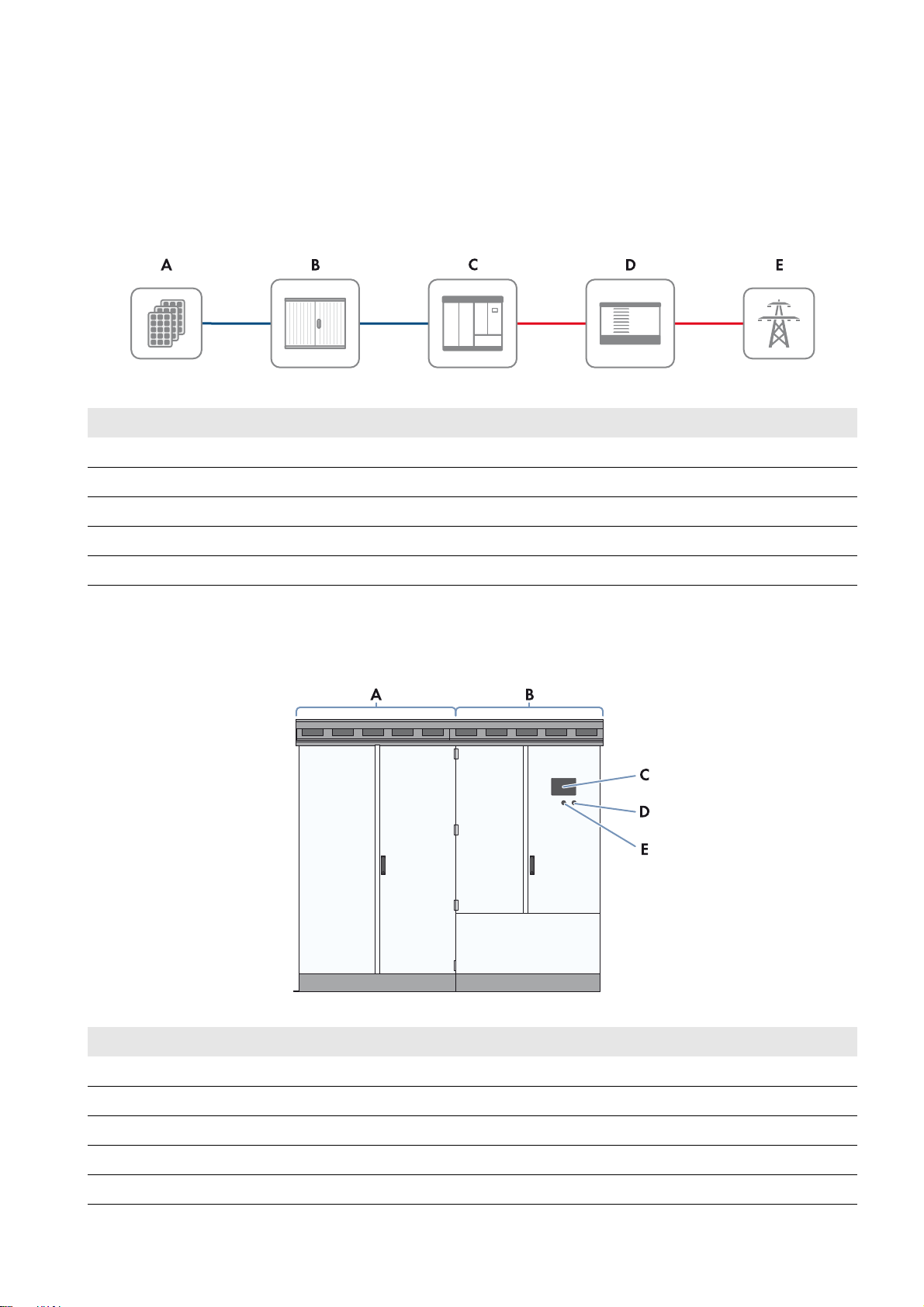
3.1 PV System Overview
The Sunny Central is a PV inverter which converts the direct current generated in the PV modules into grid-compliant
alternating current. An external MV transformer fitted downstream feeds the generated alternating current into the utility
grid.
Figure1: Principle of a grid-tie PV system with one inverter
Position Designation
A PV array
B DC sub-distribution (e.g. Sunny String-Monitor)
C Sunny Central
D External MV transformer, e.g. Transformer Compact Station with MV transformer
E Utility grid
3.2 Sunny Central
3.2.1 Design and Function of the Sunny Central
Figure2: Sunny Central (example)
Position Designation
A Inverter cabinet
B Interface cabinet
CTouch display
DService interface
EKey switch
Installation Manual SCCP-JP-IA-A4-en-12 13
Page 14
3 Product Description SMA Solar Technology AG
The Sunny Central is controlled via the Sunny Central Communication Controller (SC-COM). The grid management
service specifications from the grid operator can be implemented via a Power Reducer Box or the Power Plant Controller.
3.2.2 Type Label
The type label clearly identifies the product. There is one type label present in the Sunny Central. The type label is located
in the right-hand top corner inside the interface cabinet.
You will require the information on the type label to use the product safely and when seeking customer support from the
SMA Service Line. The type labels must be permanently attached to the product.
Reading off the serial number
You can identify the serial number without opening the Sunny Central. The serial number is located on the top left
corner of the Sunny Central roof. You can also read off the serial number from the touch display.
Reading off the firmware version
You can read off the version number of the Sunny Central and touch display firmware via the user interface.
You can also read off the version number of the touch display firmware on the touch display.
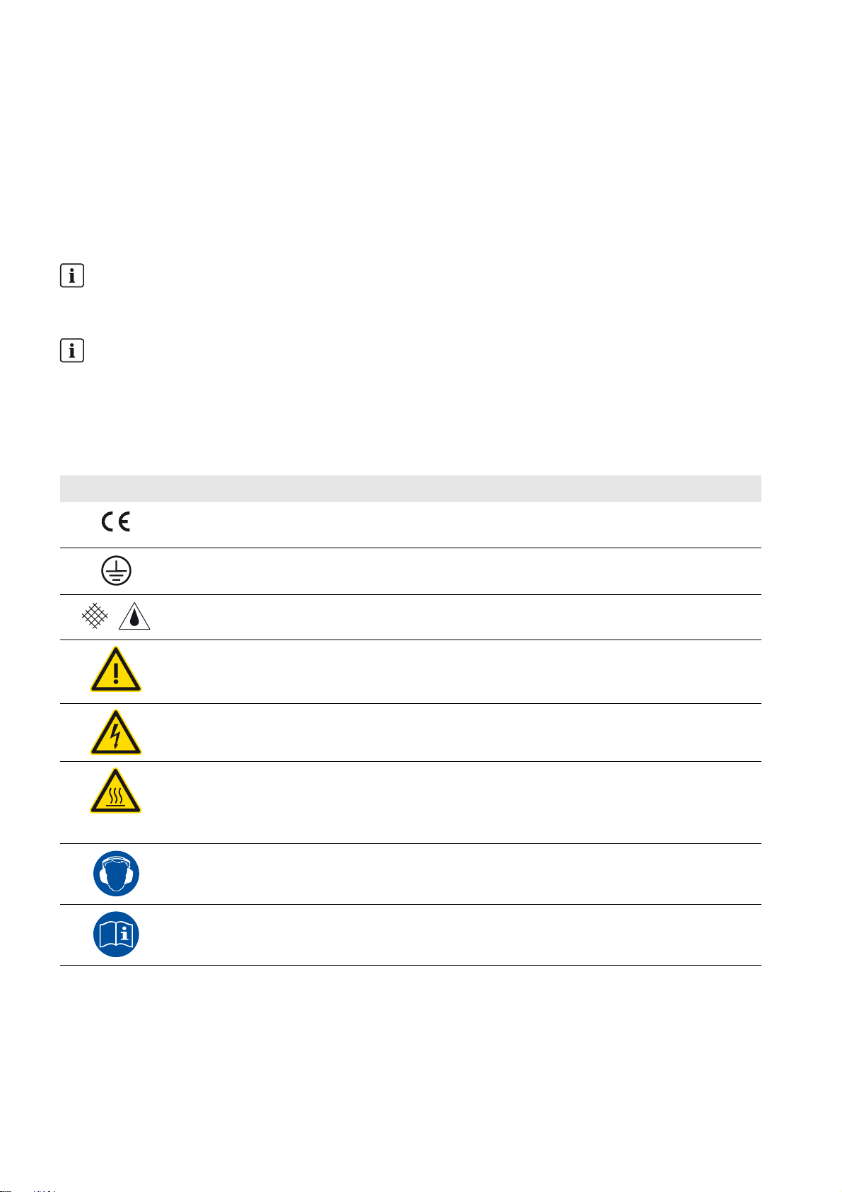
3.2.3 Symbols on the Product
All symbols on the Sunny Central and the type label are explained below.
Symbol Designation Explanation
CE marking The product complies with the requirements of the
applicable EU directives.
Protection class I All electrical equipment is connected to the grounding
conductor system of the product.
Degree of protection IP54 The product is protected against interior dust deposits
and splashing water from all angles.
Beware of a danger zone This warning symbol highlights a danger zone. Be
particularly vigilant and cautious when working on the
product.
Beware of dangerous voltage The product operates at high voltages. All work on the
product must be carried out by qualified persons only.
Beware of hot surface The product can get hot during operation. Avoid contact
during operation. Allow the product to cool down
sufficiently before carrying out any work. Wear personal
protective equipment such as safety gloves.
Use hearing protection. The product generates loud noises. When working on
the product, wear hearing protection.
Observe the documentation. Observe all documentation supplied with the product.
14 SCCP-JP-IA-A4-en-12 Installation Manual
Page 15

SMA Solar Technology AG 3 Product Description
3.2.4 Touch Display
Different kinds of Sunny Central data can be viewed on the touch display. On the touch display, you cannot set any
Sunny Central parameters, but only configure display settings such as language, time and brightness. The touch display
is fitted with a cover to protect it from weather influences. This cover can be pushed up to read the display.
The display screen is activated by touching the touch display. Tapping the symbols on the touch display activates the
corresponding functions. If the touch display has not been touched for five minutes, it will switch off.
3.2.5 Key Switch
The key switch is used to switch the Sunny Central on and off.
Switch Position "Start"
If the key switch is turned to Start, a motor drive automatically switches the DC main switch on and the Sunny Central
switches from the operating state "Stop" to the operating state "Grid monitoring". If there is sufficient irradiation and a
valid utility grid connection, the Sunny Central switches to feed-in operation. If the irradiation level, and therefore the input
voltage, is too low, the Sunny Central remains in the operating state "Grid monitoring".
Switch Position "Stop"
If the key switch is turned to Stop while the Sunny Central is in the operating state "Grid monitoring", a motor drive
automatically switches the DC main switch off. The Sunny Central switches to the operating state "Stop".
If the key switch is turned to Stop while the Sunny Central is in the operating state "MPP load operation", the
Sunny Central switches to the operating state "Shutdown". Once shutdown is complete, the AC contactor and the DC
main switch are switched off automatically and the Sunny Central switches to the operating state "Stop".
3.3 Remote Shutdown
By means of remote shutdown, you can selectively shut down and switch off the Sunny Central within approximately
six seconds, for example, from a control room. The function of the remote shutdown is similar to the stop function of the
key switch.
If the remote shutdown function is activated from the control room while the Sunny Central is in the operating state
"Grid monitoring", a motor drive automatically shuts off the DC main switch and the Sunny Central switches to the
operating state "Stop".
If the remote shutdown function is activated from the control room while the Sunny Central is in the operating state
"MPP load operation", the Sunny Central switches to the operating state "Shutdown". Once shutdown is complete, the
AC contactor and the DC main switch are switched off automatically and the Sunny Central switches to the operating
state "Stop".
The remote shutdown is designed as an open-circuit fail-safe function and must be connected to a 24 V external supply
voltage. If 24 V is present in the remote shutdown, the Sunny Central continues to operate in the current operating state.
If the remote shutdown is tripped or if a wire break occurs, 0 V is present in the remote shutdown and the Sunny Central
switches from its current operating state to the operating state "Stop".
Use of the remote shutdown will only be possible if the parameter ExlStrStpEna is set to On.
Installation Manual SCCP-JP-IA-A4-en-12 15
Page 16

3 Product Description SMA Solar Technology AG
3.4 External Fast Stop
The Sunny Central is equipped ex works with a fast stop input. An external switch that is switched via a 24 V signal can
be connected to this fast stop input.
The external fast stop disconnects the Sunny Central from the utility grid in less than 100 ms.
The Sunny Central is delivered ex works with open terminals. The following options are available for configuring the
external fast stop:
• The external fast stop is deactivated.
The terminals of the active fast stop are bridged. The fast stop function is thus deactivated. You will need to bridge
the terminals if required.
• The external fast stop is operated with internal 24 V supply.
An external latching switch (break contact) is connected to the Sunny Central terminals via the internal supply
voltage in the Sunny Central. When the switch is closed, the all-or-nothing relay is activated and the Sunny Central
feeds into the grid. If the fast stop is tripped, the switch opens and the relay is deactivated. The Sunny Central is
stopped and no longer feeds energy into the grid.
• The external fast stop is operated via an external 24 V supply.
An external latching switch (break contact) is connected to the Sunny Central terminals via an external 24 V voltage
supply. When the switch is closed, the all-or-nothing relay is activated and the Sunny Central feeds into the grid.
If the fast stop is tripped, the switch opens and the relay is deactivated. The Sunny Central is stopped and no longer
feeds energy into the grid.
Tripping of the fast stop function
The fast stop function should only be tripped in case of imminent danger. The tripping of the fast stop does not entail
rapid discharge of the capacitors. If you wish to use an external signal to switch the Sunny Central off in a controlled
manner, you should use the input of the remote shutdown function.
3.5 Grounding Concept
In accordance with the latest technology, the Sunny Central inverters are discharged to ground. As a result, leakage
currents to ground occur which must be taken into account when planning the PV system. The magnitude and distribution
of such leakage currents is influenced by the grounding concept of all the devices in the PV system. SMA Solar
Technology AG therefore recommends that when using e.g. cameras and monitoring technology, optical fiber technology
is used for the transmission of signals (see Section13.2.2 "Setting up a System Network with Optical Fibers", page67).
This will counteract possible interference sources.
The grounding of the Sunny Central and MV transformers in meshed design as recommended by SMA Solar Technology
AG reduces the level of leakage current.
3.6 Schematic Diagram
Schematic diagrams in PDF format contain jump marks. By double clicking a jump mark, the display will change to the
corresponding current path or the referenced place in the equipment list.
SMA Solar Technology AG recommends using schematic diagrams in PDF format during installation. The schematic
diagrams in PDF format are available on request. Contact the SMA Service Line.
16 SCCP-JP-IA-A4-en-12 Installation Manual
Page 17
SMA Solar Technology AG 4 Scope of Delivery
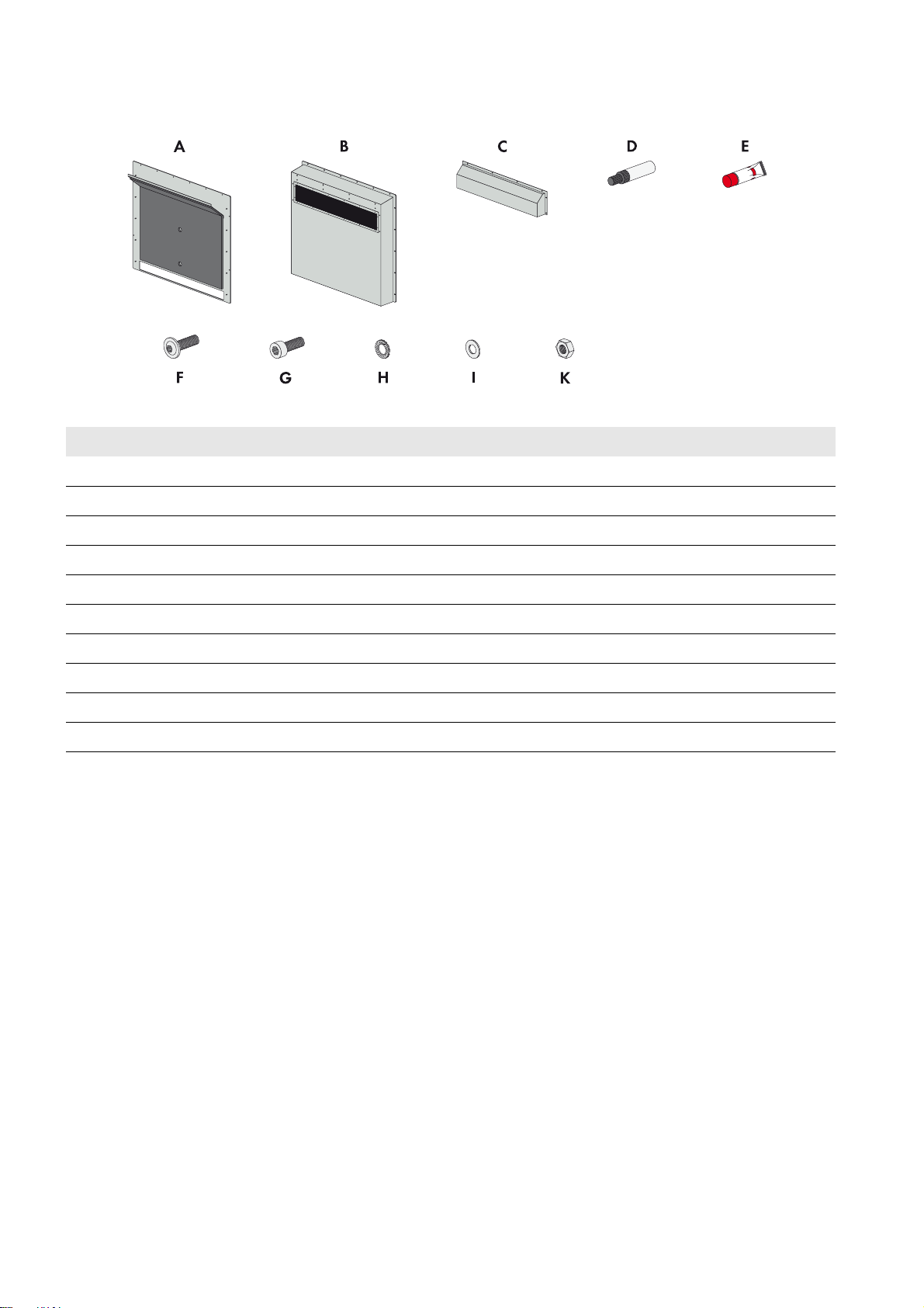
4 Scope of Delivery
Check the scope of delivery for completeness and any externally visible damage. Contact your distributor if the scope of
delivery is incomplete or damaged.
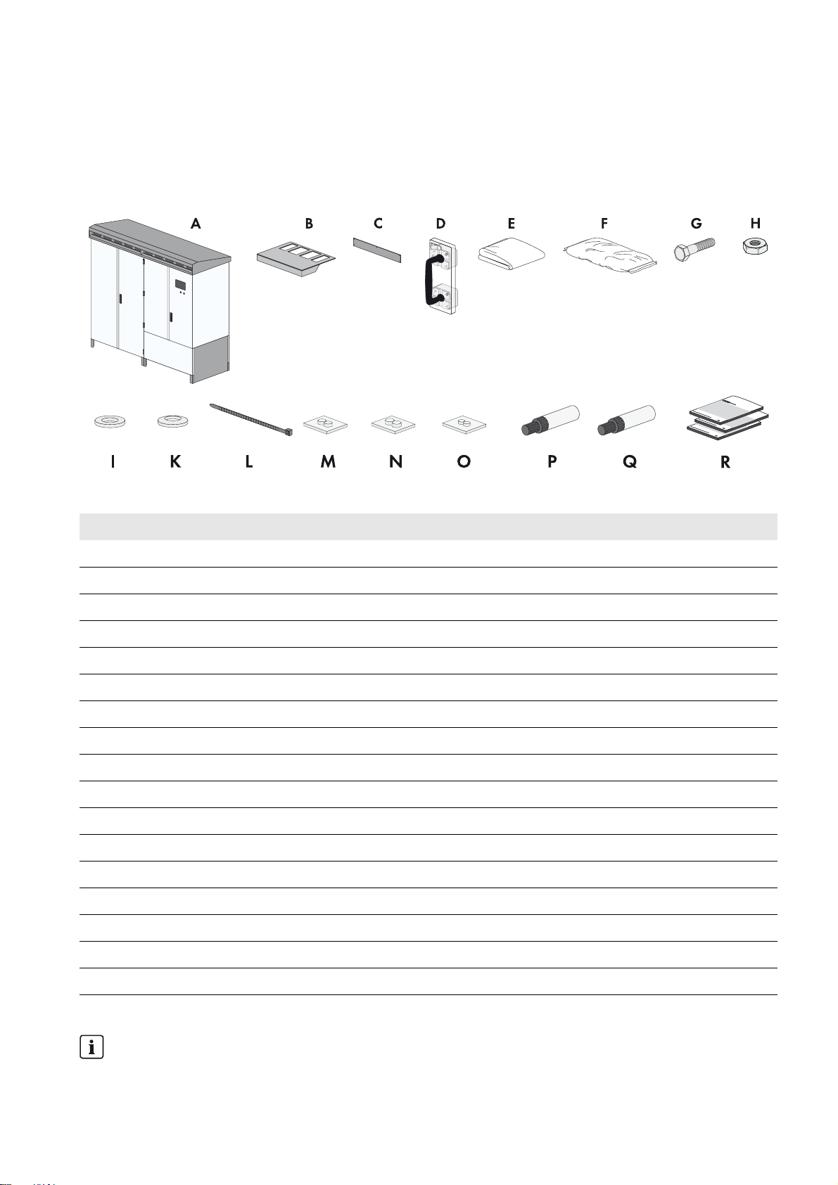
Scope of Delivery of the Inverter
Figure3: Components included in the scope of delivery of the inverter
Position Quantity Designation
A 1 Sunny Central
B 1 Ventilation plate
C5Kick plate
D 1 LV/HRC fuse handle*
E 1 Non-woven abrasive
F 1 Desiccant bag
G68Screw
H 68 Nut
I 136 Fender washer
K 136 Spring washer
L 80 Cable tie
M 1 Cable support sleeve 15 mm to 16 mm
N 1 Cable support sleeve 17 mm
O 5 Cable support sleeves 9.5 mm to 13 mm
P 1 Touch-up stick RAL 7004
Q 1 Touch-up stick RAL 9016
R 1 Installation manual, operating manual, circuit diagram, maintenance report
*For DC fuse option
Position of the LV/HRC fuse handle
With the DC fuse option, the LV/HRC fuse handle is located on the inside of the right door of the interface cabinet.
Installation Manual SCCP-JP-IA-A4-en-12 17
Page 18
4 Scope of Delivery SMA Solar Technology AG
Scope of Delivery of the Order Option "Noise reduction"
Figure4: Components of the order option "Noise reduction"
Position Quantity Designation
A 1 Silencing baffle rear panel including ventilation plate
B 1 Silencing baffle lid
C1Rain protection
D 1 Touch-up stick RAL 7035
E1OKS
®
250 allround paste
F 15 Pan head flange screw
G 9 Cylinder head screw
H7Contact washer
I14Washer
K10Hexagon nut
18 SCCP-JP-IA-A4-en-12 Installation Manual
Page 19

SMA Solar Technology AG 5 Storage
/05*$&
/05*$&
5 Storage
If the Sunny Central is to be stored prior to installation, note the following:
Penetrating moisture can damage the Sunny Central
If the Sunny Central is not stored properly, moisture can penetrate the enclosure and cause damage to electronic
components.
• Store the Sunny Central in a closed state.
• Store the Sunny Central in a dry and covered location.
• The temperature at the storage location must be between -25°C and +70°C.
An uneven foundation can damage the frame construction of the Sunny Central
Storing the inverter on an unsuitable foundation could damage the frame construction. Dust and moisture can penetrate
the inverter and damage electronic components.
• The foundation must be suitable for the weight of the Sunny Central (1,800 kg).
• The unevenness of the foundation must be less than 0.25%.
Storage in high humidity
If the Sunny Central is connected to the external supply voltage and the circuit breaker of the supply voltage is
switched on during storage, the heating system will activate automatically when humidity is high (see Section12.3.6
"Connecting the External Supply Voltage", page64).
Desiccant bag in the inverter cabinet
The desiccant bag in the inverter cabinet protects the electronic components from moisture. The desiccant bag must
be replaced by a new desiccant bag one day before commissioning.
Installation Manual SCCP-JP-IA-A4-en-12 19
Page 20
6 Preparation for Installation SMA Solar Technology AG
6 Preparation for Installation
6.1 Selecting a Mounting Location
6.1.1 Requirements for the Mounting Location
Orientation of the inverter for protection against noise
The front side of the inverter with the supply air opening is louder during operation than the rear side. Especially in
residential areas, the inverter should be oriented with the rear side facing the residential area.
Requirements:
☐ If the Sunny Central is to be installed in an electrical equipment room, an adequate supply of fresh air must be
ensured. If this is not the case, an additional ventilation system must be installed, e.g an external fan.
☐ The mounting location must be freely accessible at all times.
☐ The mounting location must be below the maximum installation altitude (see Section17 "Technical Data", page80).
☐ The ambient temperature must be within the operating temperature range (see Section17 "Technical Data",
page80).
☐ The mounting location must meet the requirements on ambient conditions (see the Technical Information "Installation
Requirements - Important Information on Transportation and Installation for Sunny Central 500CP-JP/630CP-JP/
800CP-JP").
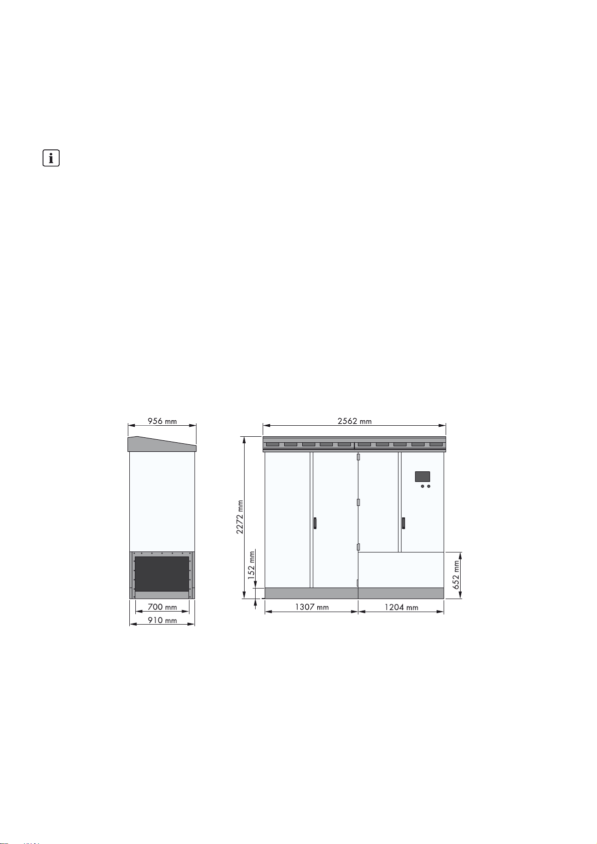
6.1.2 Dimensions of a Sunny Central
Dimensions of a Sunny Central for Outdoor Installation
Figure5: Dimensions with roof
20 SCCP-JP-IA-A4-en-12 Installation Manual
Page 21
SMA Solar Technology AG 6 Preparation for Installation
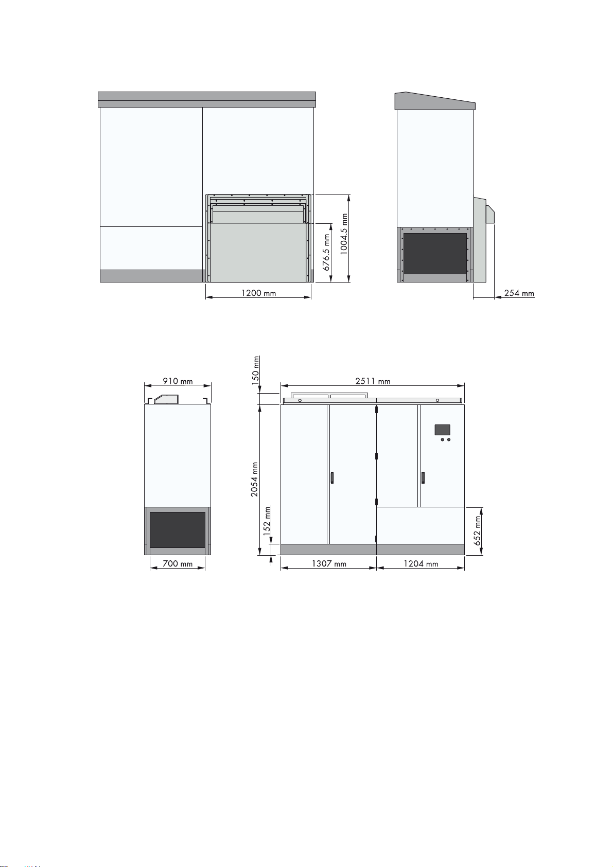
Dimensions of an optionally available silencing baffle
Figure6: Dimensions of the silencing baffle
Dimensions of the Sunny Central for Indoor Installation
Figure7: Dimensions without roof
Installation Manual SCCP-JP-IA-A4-en-12 21
Page 22

6 Preparation for Installation SMA Solar Technology AG
:$5 1,1*
/05*$&
6.1.3 Minimum Clearances for Outdoor Installation
Risk of fire due to overheating of cables
Differing cable lengths lead to overheating of the cables. Excessive heat can result in cable fires. Death or serious injury
due to fire can result.
• All line conductors from the Sunny Central to the MV transformer must be of the same length.
• The cable length between the connection points must not exceed 15 m.
Damage to the Sunny Central and the MV transformer due to intake of exhaust air
• Install the PV system in such a way that the Sunny Central cannot draw in any exhaust air. The exhaust air vent is
located at the rear of the Sunny Central.
• Install the PV system so that the exhaust air from the Sunny Central does not enter the air intake of other devices
(e.g. MV transformer).
Observe the following requirements for optimum operation of the Sunny Central:
☐ The exhaust air vents must not be obstructed or closed.
☐ The electrical equipment room must be equipped with suitable exhaust air vents.
☐ The exhaust air vents must be accessible for cleaning at all times.
Minimum Clearances for One Sunny Central
Figure8: Minimum clearances for one inverter with optionally available silencing baffle
22 SCCP-JP-IA-A4-en-12 Installation Manual
Page 23

SMA Solar Technology AG 6 Preparation for Installation
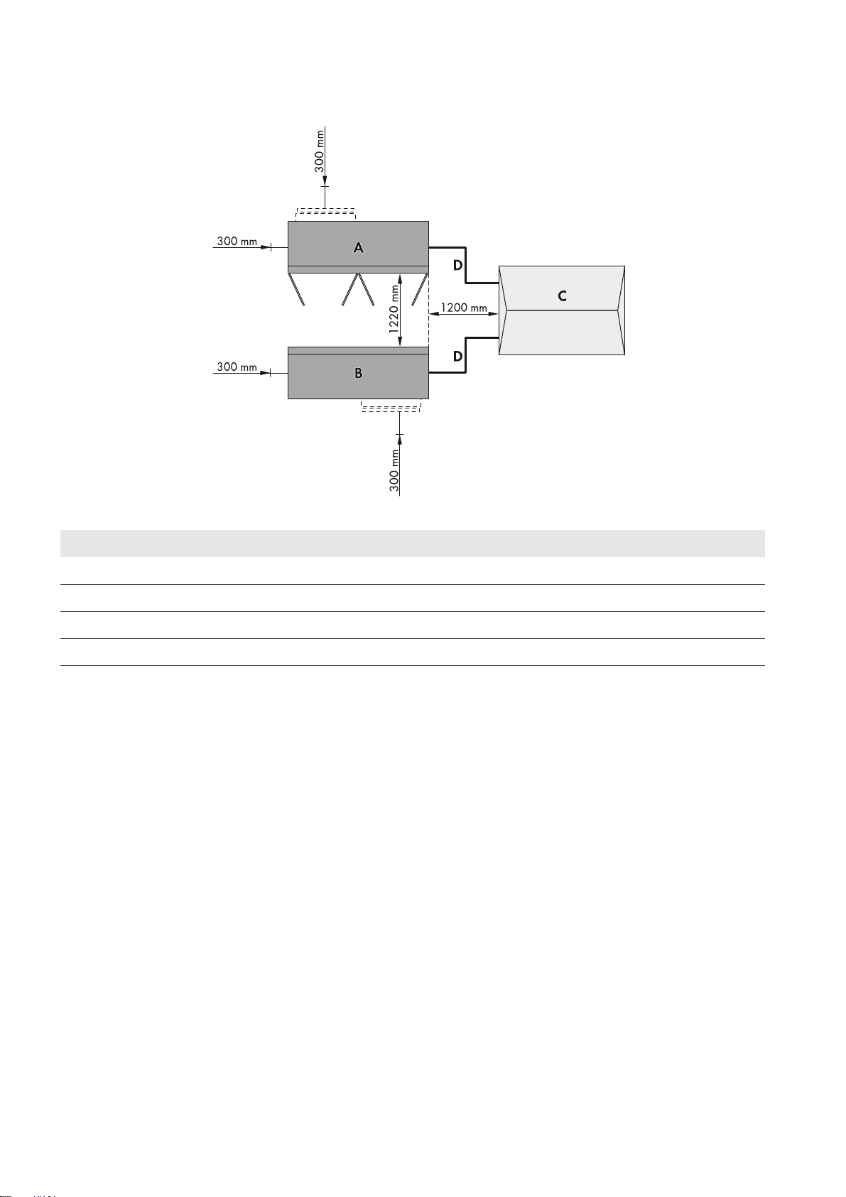
Minimum Clearances for Two Sunny Central Inverters with MV Transformer to be Installed
Outdoors
Option 1
Figure9: Option 1: Minimum clearances for two inverters with the optionally available silencing baffle and MV transformer
Position Designation
A Sunny Central 1
B Sunny Central 2
C MV transformer and medium-voltage switchgear
D Cable route between Sunny Central and MV transformer
Installation Manual SCCP-JP-IA-A4-en-12 23
Page 24
6 Preparation for Installation SMA Solar Technology AG
Option 2
Figure10: Option 2: Minimum clearances for two inverters with the optionally available silencing baffle and MV transformer
Position Designation
A Sunny Central 1
B Sunny Central 2
C MV transformer and medium-voltage switchgear
D Cable route between Sunny Central and MV transformer
24 SCCP-JP-IA-A4-en-12 Installation Manual
Page 25

SMA Solar Technology AG 6 Preparation for Installation
/05*$&
6.1.4 Minimum Clearances for Installation in Electrical Equipment Rooms
Damage to the Sunny Central and the MV transformer due to intake of exhaust air
• Install the PV system in such a way that the Sunny Central cannot draw in any exhaust air. The exhaust air vent is
located at the rear of the Sunny Central.
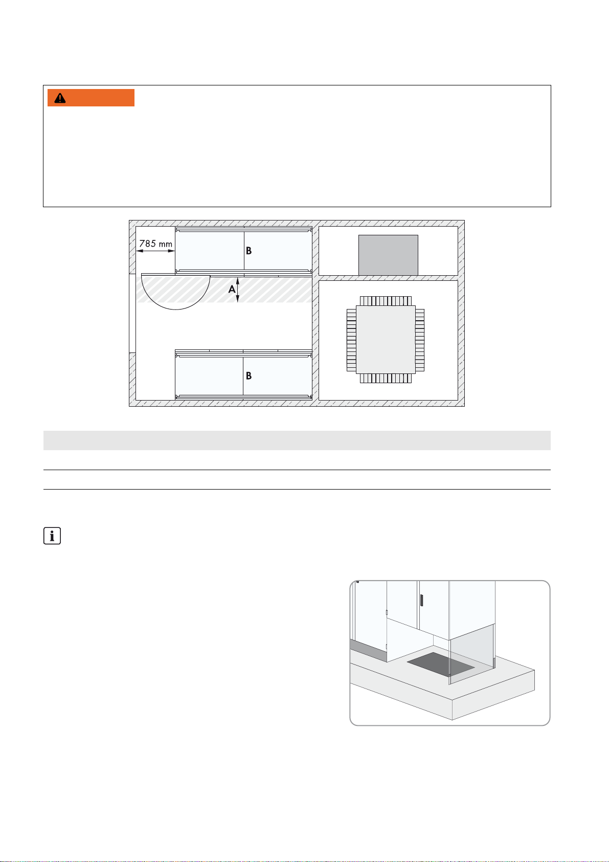
Minimum Clearances for One Sunny Central Installed in Electrical Equipment Rooms
The minimum passage width between the open door of the Sunny Central and the next fixed obstacle must be maintained.
The minimum passage width must comply with national standards. In Germany, the minimum passage width is 500 mm.
Figure11: Minimum clearances for one Sunny Central in an electrical equipment room
Position Designation
A Minimum passage width
B Sunny Central
Installation Manual SCCP-JP-IA-A4-en-12 25
Page 26
6 Preparation for Installation SMA Solar Technology AG
:$5 1,1*
Minimum Clearances for Two Sunny Central Inverters Installed in Electrical Equipment Rooms
Danger due to blocked escape route
Opening the doors of two Sunny Central inverters located opposite each other blocks the escape route. It is imperative
that the escape route is freely accessible at all times. Make sure the minimum passage width of the route meets local
standards. In Germany, the minimum passage width is 500 mm.
• Only open the door of one Sunny Central at a time.
• Comply with local requirements concerning minimum passage widths.
Figure12: Minimum clearances for two Sunny Central inverters in an electrical equipment room
Position Designation
A Minimum passage width
B Sunny Central
6.1.5 Requirements for Foundation and Cable Arrangement
Laying the cables
This manual does not specify at what stage the cables are to be laid in the foundation. The stage at which the cables
are laid must be determined individually for each PV system.
☐ Openings for the cables must be located in the foundation
underneath the interface cabinet.
☐ Empty conduits for the cables must be laid under the foundation.
☐ The data cables must be kept separate from the AC and DC
cables.
☐ There must be sufficient space available to lay the cables properly.
26 SCCP-JP-IA-A4-en-12 Installation Manual
Page 27
SMA Solar Technology AG 6 Preparation for Installation
:$5 1,1*
6.1.6 Requirements for Cable Routing between MV Transformer and
Sunny
Risk of fire due to overheating of cables
Differing cable lengths cause overheating.
• All line conductors from the Sunny Central to the MV transformer must be of the same length.
• The cable length between the connection points must not exceed 15 m.
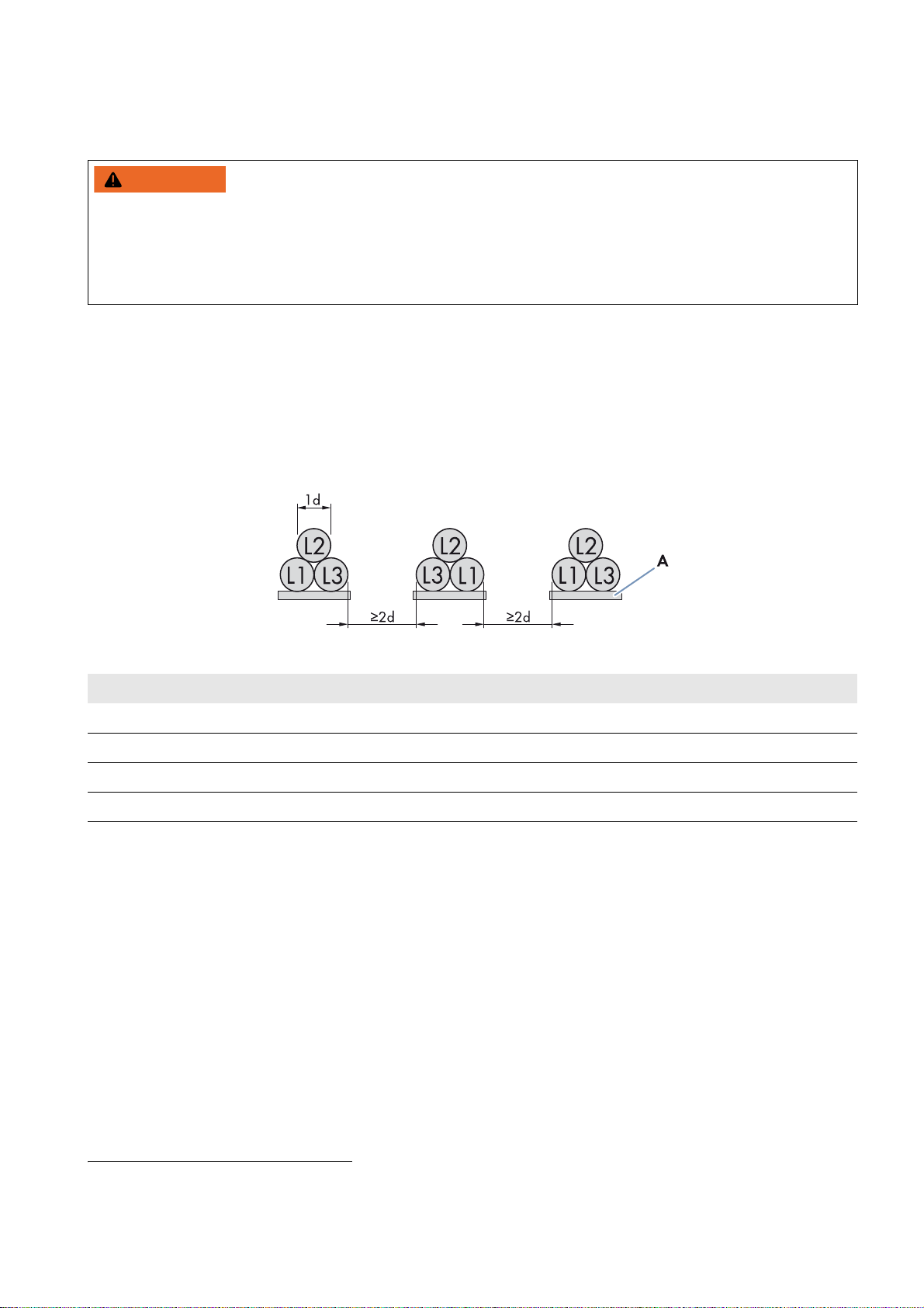
☐ The line conductors must be bundled in the three-phase system.
☐ Between the MV transformer and the Sunny Central there must be three separate cable routes for the AC cables,
e.g. cable channels.
☐ A line conductor L1, L2 and L3 must be laid in each cable channel. Ensure that the distance between the cable
bundles is at least double that of the diameter of a cable. This will prevent current imbalances. Furthermore, it is
recommended to execute cabling between inverter and transformer directly on a grounding strap. This measure
further reduces electromagnetic influences.*
Central
Figure13: Arrangement of AC cables with three cables per line conductor (example)
Position Designation
L1 Line conductor L1
L2 Line conductor L2
L3 Line conductor L3
A Grounding strap
Installation Manual SCCP-JP-IA-A4-en-12 27
* For further information, see the Technical Information "Cable Set ‒ Requirements for and Laying of Cables between Sunny Central CP and
Transformer Compact Station" at www.SMA-Solar.com.
Page 28

6 Preparation for Installation SMA Solar Technology AG
6.2 Preparation for Mounting without Base
6.2.1 Position of the Mounting Holes on the Sunny Central
The fixtures in the support surface can be prepared prior to installing the Sunny Central.
The Sunny Central must be attached to the support surface by means of six screws. Mounting holes for attaching the
inverter to the foundation or the base are located in the inverter floor.
Figure14: Position of the mounting brackets on the Sunny Central
Position Designation
A Mounting holes for mounting on a base or foundation
B Mounting holes for mounting on base
C Mounting holes for mounting on a foundation
6.2.2 Drilling Mounting Holes in the Foundation
1. Mark the positions of the mounting holes on the foundation corresponding to the mounting brackets.
2. Drill mounting holes at the marked positions.
6.3 Preparation for Mounting on a Base
Requirements:
☐ Excavation pit and subgrade must be prepared for mounting the base (see the Technical Information "Installation
requirements - Important information on transportation and installation for Sunny Central 500CP-JP ⁄ 630CP-JP /
800CP-JP").
☐ The base must be installed.
Procedure:
1. Lead the AC, DC and data cables through the opening into the base. Route the data cables separately from AC and
DC cables.
2. Seal the opening, e.g. with expanding foam. This will prevent animals from penetrating the Sunny Central.
3. Fill up the excavation pit and level off to ground level.
28 SCCP-JP-IA-A4-en-12 Installation Manual
Page 29

SMA Solar Technology AG 7 Transporting the Sunny Central
:$5 1,1*
/05*$&
7 Transporting the Sunny Central
7.1 Safety during Transport
Danger of crushing through tipping, falling or swaying of raised or suspended Sunny Central
The Sunny Central can tip or fall as a result of being lifted and transported carelessly or too fast. This can result in death
or serious injury.
• Always transport the Sunny Central as close to the ground as possible.
• Use all suspension points for transportation.
• For transport by crane, use a hoist of adequate lifting capacity for the weight of the Sunny Central of max.
1,800 kg.
• Avoid fast or jerky movements during transport.
• Keep a safe distance from the Sunny Central at all times during transport.
• All means of transport used must be designed for the weight of the Sunny Central of 1,800 kg.
Damage to the Sunny Central due to inappropriate transport
Placing the Sunny Central on uneven surfaces can cause buckling so that the doors will no longer close properly.
As a result, moisture and dust can penetrate the interior of the Sunny Central.
• Never place the Sunny Central on an unpaved, uneven surface even for a short period of time.
• Do not transport the Sunny Central with mounted kick plates.
7.2 Center of Gravity of the Sunny Central
The center of gravity of the Sunny Central is not in the middle of the Sunny Central. Keep this in mind during transportation
of the Sunny Central.
The center of gravity of the Sunny Central is marked with the center of gravity symbol on the packaging and the enclosure.
Figure15: Center of gravity symbol
7.3 Mounting the Kick Plates at the Rear of the Sunny Central
If you are installing the Sunny Central in an electrical equipment room, the kick plates must be attached at the rear of the
Sunny Central prior to aligning the Sunny Central on the mounting surface.
Procedure:
1. Screw down the grounding cables on the kick plates and ensure that they are securely fixed.
2. Bring the kick plates into the correct position at the rear of the Sunny Central.
3. Attach the kick plates to the Sunny Central using a Torx screwdriver (torque: 2 Nm to 3 Nm).
Installation Manual SCCP-JP-IA-A4-en-12 29
Page 30

7 Transporting the Sunny Central SMA Solar Technology AG
:$5 1,1*
:$5 1,1*
7.4 Transporting the Sunny Central Using a Crane Fork
Danger of crushing if the Sunny Central tips over
With the kick plates mounted at the rear of the Sunny Central, the supporting surface of the Sunny Central on the forks
of the crane fork is inadequate. Vibrations during transport may cause the Sunny Central to slip off the crane fork and
tip over. This can result in death or serious injury.
• When the kick plates are mounted, always stabilize the Sunny Central with crane slings or steel chains during
transport.
Requirements:
☐ The crane and crane fork must be designed to take the weight of the Sunny Central of 1,800 kg.
☐ The crane fork must be properly coupled to the crane.
☐ All kick plates must be removed.
Procedure:
1. Position the forks of the crane fork underneath the Sunny Central
from the front or rear. Take the center of gravity of the
Sunny Central into account and move the crane fork right under
the Sunny Central.
2. Slowly raise the crane fork with the Sunny Central.
3. Transport the Sunny Central to the mounting location and set down on a suitable surface.
7.5 Transporting the Sunny Central Using a Forklift
Danger of crushing if the Sunny Central tips over
With the kick plates mounted at the rear of the Sunny Central, the supporting surface of the Sunny Central on the forks
of the forklift is inadequate. Vibrations during transport may cause the Sunny Central to slip off the forklift and tip over.
This can result in death or serious injury.
• When the kick plates are mounted, always stabilize the Sunny Central with crane slings or steel chains during
transport.
Requirements:
☐ The forklift must be designed to take the weight of the Sunny Central.
☐ All kick plates must be removed.
30 SCCP-JP-IA-A4-en-12 Installation Manual
Page 31

SMA Solar Technology AG 7 Transporting the Sunny Central
Procedure:
1. Position the forklift under the Sunny Central either from the front or
the rear. Take the center of gravity of the Sunny Central into
account and move the forklift truck right under the Sunny Central.
2. Stabilize the Sunny Central using e.g. tension belts.
3. Slightly raise the Sunny Central.
4. Transport the Sunny Central to the mounting location and set down on a suitable surface.
7.6 Transporting the Sunny Central Using a Pallet Truck
Requirements:
☐ The pallet truck must be designed to take the weight of the Sunny Central.
☐ All kick plates must be removed.
Procedure:
1. If the Sunny Central is to be transported on a wooden pallet, move
the pallet truck under the Sunny Central from the front or the rear.
2. If the Sunny Central is to be transported without a wooden pallet,
the pallet truck must always be moved under the Sunny Central
from the side. Ensure that the side panels of the Sunny Central are
not damaged by the forks.
3. Slightly raise the Sunny Central.
4. Transport the Sunny Central to the mounting location and set
down on a suitable surface.
Installation Manual SCCP-JP-IA-A4-en-12 31
Page 32

7 Transporting the Sunny Central SMA Solar Technology AG
&$87,21
/05*$&
7.7 Transporting the Sunny Central Using a Crane
To transport the Sunny Central by crane, you will first need to disassemble the roof.
7.7.1 Disassembling the Roof of the Sunny Central
Danger of crushing due to heavy, unwieldy roof
The roof of the Sunny Central is unwieldy and weighs 30 kg. If you try to move the roof on your own, you run a risk of
having limbs crushed.
• Only move the roof with at least two persons.
Property damage due to rupture of grounding conductors
The roof is connected to the Sunny Central by grounding conductors. If the roof is not removed correctly, the grounding
conductors may be pulled out.
• Take care not to damage the grounding conductors when disassembling the roof.
Procedure:
1. Release the screws of the right-hand ventilation grid.
2. Pull the lower side of the right-hand ventilation grid forwards to
remove it.
3. Release the screws of the left-hand ventilation grid.
32 SCCP-JP-IA-A4-en-12 Installation Manual
Page 33

SMA Solar Technology AG 7 Transporting the Sunny Central
4. Pull the lower side of the left-hand ventilation grid forwards to
remove it.
5. Pull the front edge of the roof forward and push upward.
6. Gently push the roof to the rear to slide it out of the guide rails.
7. Release the grounding conductor from the Sunny Central.
8. Remove the Sunny Central roof and set down on a suitable surface.
Installation Manual SCCP-JP-IA-A4-en-12 33
Page 34

7 Transporting the Sunny Central SMA Solar Technology AG
&$87,21
7.7.2 Transporting the Sunny Central Using a Crane
Requirements:
☐ The crane and hoist must be designed to take the weight of the Sunny Central.
☐ The hoist must be properly connected to the crane.
☐ The roof of the Sunny Central must be dismantled.
Procedure:
1. Attach the hoist to all four lifting eyes in the Sunny Central.
2. Raise the crane hook slowly until the hoist is taut.
3. Ensure that the hoist is attached correctly.
4. Slightly raise the Sunny Central.
5. Transport the Sunny Central as close to the ground as possible.
6. Transport the Sunny Central to the mounting location and set down on a suitable surface.
7.7.3 Mounting the Roof of the Sunny Central
Danger of crushing due to heavy, unwieldy roof
The roof of the Sunny Central is unwieldy and weighs 30 kg. If you try to move the roof on your own, you run a risk of
having limbs crushed.
• Only move the roof with at least two persons.
Procedure:
1. Position the roof on the Sunny Central.
2. Tighten the grounding conductor on the Sunny Central
(torque: 14.2 Nm).
34 SCCP-JP-IA-A4-en-12 Installation Manual
Page 35

SMA Solar Technology AG 7 Transporting the Sunny Central
3. Slide the roof into the rail on the Sunny Central and pull forwards.
4. Press the roof downwards.
5. Insert the left-hand ventilation grid.
6. Screw the left-hand ventilation grid on (torque: 20 Nm).
7. Insert the right-hand ventilation grid.
8. Screw the right-hand ventilation grid on (torque: 20 Nm).
Installation Manual SCCP-JP-IA-A4-en-12 35
Page 36

8 Installing the Sunny Central SMA Solar Technology AG
8 Installing the Sunny Central
Depending on the order option , the Sunny Central can be installed directly on the foundation without a base or attached
to a base. You must select the relevant section.
8.1 Attaching the Sunny Central without Base
Once the Sunny Central has been aligned on the foundation, you can attach it to the foundation using concrete screw
anchors and screws.
Requirements:
☐ The mounting surface must be prepared for installation (see Section6.2 "Preparation for Mounting without Base",
page28).
☐ The Sunny Central must be taken off the Euro pallet.
Additionally required material (not included in the scope of delivery):
☐ 4 suitable concrete screw anchors
Procedure:
• Insert the concrete screw anchors through the brackets of the Sunny Central in the foundation. The exact procedure
depends on the type of screw anchors used.
8.2 Installing the Sunny Central on a Base
Once the Sunny Central has been aligned on the base, you can attach it to the base with screws. The screws for attaching
the inverter to the base are included in the scope of delivery of the base.
Requirements:
☐ The base must be prepared for installation (see Section6.3 "Preparation for Mounting on a Base", page28).
☐ The Sunny Central must be taken off the Euro pallet.
Procedure:
• Insert the screws through the brackets on the Sunny Central in the base and screw tight.
36 SCCP-JP-IA-A4-en-12 Installation Manual
Page 37

SMA Solar Technology AG 8 Installing the Sunny Central
/05*$&
/05*$&
8.3 Disassembling the Panels on the Connection Area
The panels are located at the bottom of the interface cabinet of the Sunny Central.
Property damage due to rupture of grounding conductors
The panels are connected to the Sunny Central via grounding conductors. If the panels are not removed correctly,
the grounding conductors may be pulled out.
• Take care not to damage the grounding conductors when disassembling the panels.
Procedure:
1. Remove the panel screws using a Torx screwdriver (T30).
2. Carefully remove the front panel of the connection area. Pull the panel forwards by 80 mm to 100 mm.
3. Detach the grounding conductor from the rear side of the panel.
4. Remove the panels.
8.4 Removing the Transport Lock from the Inverter Cabinet
Damage to electronic components due to electrostatic discharge
Electrostatic discharge can destroy components.
• When working on the Sunny Central or handling assemblies, observe the ESD safety regulations and wear safety
gloves.
• Discharge electrostatic charge by touching uncoated, grounded enclosure parts (e.g. at grounding connection on
the doors). Only then is it safe to touch electronic components.
Depending on the production version, the three inverter bridges are secured for transport with ESD bubble wrap.
Procedure:
1. Open the inverter cabinet.
2. Remove the bubble wrap from each of the three inverter bridges.
Be sure to observe all ESD protection measures.
3. Close the inverter cabinet.
Installation Manual SCCP-JP-IA-A4-en-12 37
Page 38

8 Installing the Sunny Central SMA Solar Technology AG
8.5 Mounting the Silencing Baffle
For order option "Noise reduction", a silencing baffle will be delivered with the inverter. The silencing baffle must be
mounted to the rear panel of the inverter cabinet. When mounting, use the allround paste from the scope of delivery for
the bolted connections.
Procedure:
To mount the silencing baffle, perform the following actions in the specified order. The following sections describe the
exact procedure.
• Mounting the rear panel of the silencing baffle
• Mounting the lid of the silencing baffle
• Mounting the rain protection
Mounting the Rear Panel of the Silencing Baffle
Required mounting material:
☐ 2 cylinder head screws
☐ 2 contact washers
Procedure:
1. Align the rear panel of the silencing baffle at the rear panel of the
inverter.
2. Screw two cylinder head screws with contact washers into the
middle thread of the rear panel. The rear panel of the silencing
baffle must remain flexible.
38 SCCP-JP-IA-A4-en-12 Installation Manual
Page 39

SMA Solar Technology AG 8 Installing the Sunny Central
Mounting the Lid of the Silencing Baffle
Required mounting material:
☐ 1 cylinder head screw
☐3 contact washers
☐ 9 pan head flange screws
☐ 13 washers
☐ 10 hexagon nuts
Procedure:
1. Align the lid at the rear panel. Push the lid over the stud bolt.
2. Screw the cylinder head screw with contact washer into the upper
left thread. Do not yet tighten the screw.
3. Screw five pan head flange screws into the upper threads of the
lid. Do not yet tighten the screws.
4. Screw the ventilation plate of the rear panel of the silencing baffle
to the lid. Do not yet tighten the four pan head flange screws.
5. Screw two hexagon nuts with contact washers to the right-hand
and left-hand lower stud bolts of the rear panel.
Installation Manual SCCP-JP-IA-A4-en-12 39
Page 40

8 Installing the Sunny Central SMA Solar Technology AG
6. Screw all washers and hexagon nuts to the remaining stud bolts of
the rear panel.
7. Align the lid and tighten all screws and nuts (torque: 8 Nm).
Mounting the Rain Protection
Required mounting material:
☐ 2 cylinder head screws
☐ 2 contact washers
☐ 6 pan head flange screws
Procedure:
1. Align the rain protection at the silencing baffle.
2. Screw two cylinder head screws with contact washers into the
right-hand and left-hand lower thread of the lid and tighten
(torque: 8 Nm).
3. Screw six pan head flange screws into the thread and tighten
(torque: 8 Nm).
40 SCCP-JP-IA-A4-en-12 Installation Manual
Page 41

SMA Solar Technology AG 8 Installing the Sunny Central
8.6 Replacing the Desiccant Bag in the Inverter Cabinet
Desiccant bag in the inverter cabinet
The desiccant bag in the inverter cabinet protects the electronic components from moisture. The desiccant bag must
be replaced by a new desiccant bag one day before commissioning.
Procedure:
1. Open the inverter cabinet.
2. Remove and dispose of the desiccant bags located under the inverter bridge.
3. Remove the foil from the desiccant bag included in the scope of delivery and position it under the inverter bridges.
4. Close the inverter cabinet.
8.7 Mounting the Ventilation Plate
The guide rails for the ventilation plate are located in the floor area of the inverter cabinet.
Procedure:
• Slide the ventilation plate into the guide rails in the inverter cabinet. The ventilation grid in the ventilation plate is
facing the rear panel.
☑ The ventilation plate is flush with the Sunny Central.
✖ The ventilation plate will not go all the way in?
• Grasp the ventilation plate from underneath and press the middle part upwards while sliding it in.
Installation Manual SCCP-JP-IA-A4-en-12 41
Page 42

9 Grounding Terminal SMA Solar Technology AG
9 Grounding Terminal
9.1 Cable and Terminal Lug Requirements
Cables:
☐ Use copper or aluminum cables only.
☐ Maximum cable cross-section: 400 mm
Terminal lugs:
☐ Only use tin-plated terminal lugs.
☐ Only use the nuts, screws and washers included in the scope of delivery for the connection.
☐ Always connect two-hole terminal lugs with two screws.
☐ The terminal lugs must be designed for temperatures of at least +95°C.
☐ The width of the terminal lugs must exceed the washer diameter (32 mm). This will ensure that the defined torques
are effective over the whole surface.
9.2 Grounding
2
Equipotential bonding
• Ground the Sunny Central in accordance with the applicable regulations.
Figure16: Connecting with one terminal lug
Position Designation
ANut
BSpring washer
CFender washer
D Busbar
42 SCCP-JP-IA-A4-en-12 Installation Manual
Page 43

SMA Solar Technology AG 9 Grounding Terminal
Position Designation
E1 Tin-plated one-hole terminal lug
E2 Tin-plated two-hole terminal lug
FScrew M12
Additionally required mounting material (not included in the scope of delivery):
☐Clean cloth
☐ Ethanol cleaning agent
Requirement:
☐ Do not attach more than one cable to the connection bracket.
Procedure:
1. Lead the cables into the interface cabinet.
2. Strip the cable insulation.
3. Fit the cables with terminal lugs.
4. Wipe the contact surfaces on the terminal lugs and grounding busbar with a clean cloth and ethanol cleaning agent.
5. Do not touch the contact surfaces again after cleaning.
6. Connect the cables to the grounding busbar in accordance with the circuit diagram. Only use the screws, nuts and
washers included in the scope of delivery (torque: 37 Nm).
7. Secure the cables on the cable support rail. This will prevent the cables from being pulled out inadvertently.
Installation Manual SCCP-JP-IA-A4-en-12 43
Page 44

10 DC Connection SMA Solar Technology AG
'$1*(5
10 DC Connection
Depending on the order option, the DC connection procedure may differ. You must select the relevant section.
10.1 Safety during DC Connection
Danger to life from electric shock due to live voltage
High voltages are present in the live components of the Sunny Central. Touching live components results in death or
serious injury due to electric shock.
• When working in a high contact-risk environment, wear personal protective equipment.
• Do not touch any live components.
• Follow the instructions precisely.
• Observe all warning messages on the product and in the documentation.
• Observe all safety precautions of the module manufacturer.
• Provided live voltage is not absolutely necessary, always disconnect the following components from voltage
sources before performing any work on the inverter:
– Grid voltage for grid feed-in
– Internal power supply
– DC voltage from the PV array
– Additional external voltages, e.g. control signals from a control room
• Ensure that no disconnected components can be reconnected.
• Wait 15 minutes after switching off the inverter before opening it. This will ensure that the capacitors are
discharged.
• Before working on the Sunny Central, check that all devices are completely voltage-free.
• Ground and short-circuit.
• Cover or isolate any adjacent live components.
Danger to life from electric shock due to live DC cables
DC cables connected to PV modules that are exposed to sunlight carry live voltage. Touching live components results
in death or serious injury.
• Prior to connecting the DC cables, ensure that the DC cables are voltage-free.
• Wear suitable personal protective equipment for all work on the Sunny Central.
Danger to life from electric shock due to ground fault
If a ground fault has occurred, parts of the PV system that are supposedly grounded may in fact be live. Touching system
components that have not been properly grounded results in death or serious injuries from electric shock.
• Before working on the PV system, ensure that no ground fault is present.
• Wear suitable personal protective equipment for all work on the device.
Danger to life from electric shock when entering the PV field
The insulation monitoring with GFDI, Remote GFDI or Soft Grounding does not provide protection from injury when
GFDI is activated. PV modules grounded by GFDI discharge voltage to ground. When entering the PV field, lethal
electric shocks may occur.
• The inverter must be installed in a closed operating area.
• Before entering the PV field, switch the PV array to insulated operation.
• Ensure that the insulation resistance of the PV field is greater than 1 k Ω .
44 SCCP-JP-IA-A4-en-12 Installation Manual
Page 45

SMA Solar Technology AG 10 DC Connection
:$5 1,1*
Risk of fire due to failure to observe torque specifications on live bolted connections
Failure to follow the specified torques reduces the ampacity of live bolted connections so that the contact resistances
increase. This can cause components to overheat and catch fire.
• Ensure that live bolted connections are always tightened with the exact torque specified in this document.
• When working on the device, use suitable tools only.
• Avoid repeated tightening of live bolted connections as this may result in inadmissibly high torques.
DC-side disconnection
The DC main distributions and DC sub-distributions should be equipped with circuit breakers. Circuit breakers
enable trouble-free DC-side disconnection of the inverter.
10.2 DC Connection with DC Fuse Option
10.2.1 Cable and Terminal Lug Requirements
Reduced DC input currents
The DC inputs are fused with LV/HRC size-3 fuses.
Thermal stress and fluctuating loads on the Sunny Central result in a screening factor of 0.7. This screening factor
must be taken into account in the DC cable design.
Fusing Reduced DC current
125 A 87.5 A
160 A 112.0 A
200 A 140.0 A
250 A 175.0 A
315 A 220.5 A
400 A 280.0 A
Cables:
☐ Use copper or aluminum cables only.
☐ Maximum cable cross-section: 400 mm
Terminal lugs:
☐ Use tin-plated terminal lugs only.
☐ Only use the nuts, screws and washers included in the scope of delivery for the connection.
☐ Always connect two-hole terminal lugs with two screws.
2
☐ The terminal lugs must be designed for temperatures of at least +95°C.
☐ The width of the terminal lugs must exceed the washer diameter (32 mm). This will ensure that the defined torques
Installation Manual SCCP-JP-IA-A4-en-12 45
are effective over the whole surface.
Page 46

10 DC Connection SMA Solar Technology AG
10.2.2 Connection Area with DC Fuse Option
Figure17: Connection area for DC fuses (example)
Position Designation
A Grounding busbar
B Connection bracket for DC cable*
C Connection bracket for DC cable*
D Connection bracket for AC cable
E DC connection bracket with dimensions
* The polarity of the connection brackets is marked with labels.
46 SCCP-JP-IA-A4-en-12 Installation Manual
Page 47

SMA Solar Technology AG 10 DC Connection
10.2.3 Connection with One Terminal Lug
Figure18: Connecting with terminal lug for terminals with single assignment
Position Designation
ANut
BSpring washer
CFender washer
D Aluminum busbar
E1 Tin-plated one-hole terminal lug
E2 Tin-plated two-hole terminal lug
FScrew M12
Installation Manual SCCP-JP-IA-A4-en-12 47
Page 48

10 DC Connection SMA Solar Technology AG
10.2.4 Connection with Two Terminal Lugs
Figure19: Connecting with terminal lugs for terminals with double assignment
Position Designation
ANut
BSpring washer
CFender washer
D1 Tin-plated one-hole terminal lug
D Tin-plated two-hole terminal lug
E Aluminum busbar
FScrew M12
48 SCCP-JP-IA-A4-en-12 Installation Manual
Page 49

SMA Solar Technology AG 10 DC Connection
10.2.5 Connecting the SMB Connection Kit to DC Fuses
To connect the Sunny Main Box to the Sunny Central, you need the SMB Connection Kit. You can only connect the
SMB Connection Kit to a Sunny Central with DC fuses. The SMB Connection Kit busbar links three of the Sunny Central
DC terminals and allows up to four DC cables to be connected.
Procedure:
1. Position and screw the busbar firmly over three DC terminals
(torque: 60 Nm).
2. Pull the fuses out of the three DC connection brackets. Use the LV/HRC fuse handle.
10.2.6 Connecting the DC Cables
Additionally required mounting material (not included in the scope of delivery):
☐Clean cloth
☐ Ethanol cleaning agent
Requirement:
☐ No more than two DC cables must be connected to each fuse input.
Procedure:
1. Insert the DC cables in the interface cabinet.
2. Strip the DC cable insulation.
3. Fit terminal lugs to the DC cables.
4. Wipe the contact surfaces on the terminal lugs and connection brackets with a clean cloth and ethanol cleaning
agent.
5. For non-tin-plated busbars, also polish the contact surfaces with non-woven abrasive as follows:
• Clean the contact surfaces with the non-woven abrasive until they have a light metallic sheen. Ensure that the
coated contact surfaces are not damaged.
• Remove metal dust with a clean cloth and ethanol cleaning agent.
6. Do not touch the contact surfaces again after cleaning.
7. Connect the DC cables in accordance with the circuit diagram (torque: 37 Nm). Only use the screws, nuts and
washers included in the scope of delivery and make sure that the screw heads always point forwards.
8. Secure the DC cables on the cable support rail. This will prevent the cables from being pulled out inadvertently.
Installation Manual SCCP-JP-IA-A4-en-12 49
Page 50

10 DC Connection SMA Solar Technology AG
10.3 DC Connection with DC Busbar Option
10.3.1 Cable and Terminal Lug Requirements
Cables:
☐ Use copper or aluminum cables only.
☐ Maximum cable cross-section: 400 mm
Terminal lugs:
☐ Use tin-plated terminal lugs only.
☐ Only use the nuts, screws and washers included in the scope of delivery for the connection.
☐ Always connect two-hole terminal lugs with two screws.
☐ The terminal lugs must be designed for temperatures of at least +95°C.
☐ The width of the terminal lugs must exceed the washer diameter (32 mm). This will ensure that the defined torques
are effective over the whole surface.
10.3.2 Connection Area with DC Busbar Option
2
Figure20: Dimensions of the DC busbar (example)
Position Designation
A Grounding busbar
B Connection bracket for DC‒ cable
C Connection bracket for DC+ cable
D Connection bracket for AC cable
50 SCCP-JP-IA-A4-en-12 Installation Manual
Page 51

SMA Solar Technology AG 10 DC Connection
Position Designation
E DC connection bracket with dimensions
10.3.3 Connection with One Terminal Lug
Figure21: Connecting with terminal lug for terminals with single assignment
Position Designation
ANut
BSpring washer
CFender washer
D Aluminum busbar
E1 Tin-plated one-hole terminal lug
E2 Tin-plated two-hole terminal lug
FScrew M12
Installation Manual SCCP-JP-IA-A4-en-12 51
Page 52

10 DC Connection SMA Solar Technology AG
10.3.4 Connection with Two Terminal Lugs
Figure22: Connecting with terminal lugs for terminals with double assignment
Position Designation
ANut
BSpring washer
CFender washer
D1 Tin-plated one-hole terminal lug
D Tin-plated two-hole terminal lug
E Aluminum busbar
FScrew M12
52 SCCP-JP-IA-A4-en-12 Installation Manual
Page 53

SMA Solar Technology AG 10 DC Connection
10.3.5 Connecting the DC Cables
Requirement:
☐ No more than two DC cables must be connected to each fuse input.
Additionally required mounting material (not included in the scope of delivery):
☐Clean cloth
☐ Ethanol cleaning agent
Procedure:
1. Insert the DC cables in the interface cabinet.
2. Strip the DC cable insulation.
3. Fit terminal lugs to the DC cables.
4. Wipe the contact surfaces on the terminal lugs and connection brackets with a clean cloth and ethanol cleaning
agent.
5. Do not touch the contact surfaces again after cleaning.
6. Connect the DC cables in accordance with the circuit diagram (torque: 37 Nm). Only use the screws, nuts and
washers included in the scope of delivery and make sure that the screw heads always point forwards.
7. Secure the DC cables on the cable support rail. This will prevent the cables from being pulled out inadvertently.
Installation Manual SCCP-JP-IA-A4-en-12 53
Page 54

11 AC Connection SMA Solar Technology AG
'$1*(5
:$5 1,1*
11 AC Connection
11.1 Safety during AC Connection
Danger to life from electric shock due to live voltage
High voltages are present in the live components of the low-voltage and medium-voltage grids. Touching live
components results in death or serious injury due to electric shock.
• When working in a high contact-risk environment, wear personal protective equipment.
• Do not touch any live components.
• Follow the instructions precisely.
• Observe all warning messages on the product and in the documentation.
• Observe all locally applicable safety regulations for working on the low-voltage and medium-voltage grids.
• Provided live voltage is not absolutely necessary, always disconnect the following components from voltage
sources before performing any work on the inverter:
– Grid voltage for grid feed-in
– Internal power supply
– DC voltage from the PV array
– Additional external voltages, e.g. control signals from a control room
• Ensure that no disconnected components can be reconnected.
• Wait 15 minutes after switching off the inverter before opening it. This will ensure that the capacitors are
discharged.
• Before working on the Sunny Central, check that all devices are completely voltage-free.
• Ground and short-circuit.
• Cover or isolate any adjacent live components.
Risk of fire due to failure to observe torque specifications on live bolted connections
Failure to follow the specified torques reduces the ampacity of live bolted connections so that the contact resistances
increase. This can cause components to overheat and catch fire.
• Ensure that live bolted connections are always tightened with the exact torque specified in this document.
– Observe a torque of 37 Nm for connections with tin-plated aluminum terminal lugs on copper bar.
– Observe a torque of 60 Nm for connections with tin-plated copper terminal lugs on copper bar.
• When working on the device, use suitable tools only.
• Avoid repeated tightening of live bolted connections as this may result in inadmissibly high torques.
54 SCCP-JP-IA-A4-en-12 Installation Manual
Page 55

SMA Solar Technology AG 11 AC Connection
11.2 Connecting the AC Cables
11.2.1 Cable and Terminal Lug Requirements
Cables:
☐ Use copper or aluminum cables only.
☐ Maximum cable cross-section: 325 mm
☐For the inverter types Sunny Central 630CP-JP and Sunny Central 800CP-JP, the AC cables must be designed for
maximum voltages of 1,450 V to ground and a root-mean-square value of 800 V.
☐ For the inverter type Sunny Central 500CP-JP, the AC cables must be designed for maximum voltages of 800 V to
ground and a root-mean-square value of 390 V.
☐ All cables of the line conductors must be of the same length.
Terminal lugs:
☐ Use tin-plated terminal lugs only.
☐ Only use the nuts, screws and washers included in the scope of delivery for the connection.
☐ Always connect two-hole terminal lugs with two screws.
☐ The terminal lugs must be designed for temperatures of at least +95°C.
2
☐ The width of the terminal lugs must exceed the washer diameter (32 mm). This will ensure that the defined torques
are effective over the whole surface.
11.2.2 Connection with One Terminal Lug
Figure23: Connecting with terminal lug for terminals with single assignment
Position Designation
ANut
BSpring washer
CFender washer
D Copper busbar
E Tin-plated one-hole terminal lug
FScrew M12
Installation Manual SCCP-JP-IA-A4-en-12 55
Page 56

11 AC Connection SMA Solar Technology AG
11.2.3 Connection with Two Terminal Lugs
Figure24: Connecting with terminal lugs for terminals with double assignment
Position Designation
ANut
BSpring washer
CFender washer
D Tin-plated one-hole terminal lug
E Copper bar
FScrew M12
11.2.4 Connecting the AC Cables
Figure25: Dimensions of the AC connection brackets
Additionally required mounting material (not included in the scope of delivery):
☐Clean cloth
☐ Ethanol cleaning agent
Requirement:
☐ The AC cables must be prepared for the connection.
56 SCCP-JP-IA-A4-en-12 Installation Manual
Page 57

SMA Solar Technology AG 11 AC Connection
Procedure:
1. Insert the AC cables in the interface cabinet.
2. Strip the AC cable insulation.
3. Fit the AC cables with terminal lugs.
4. Clean the contact surfaces using a clean cloth and ethanol cleaning agent.
5. Clean the contact surfaces with the non-woven abrasive until they have a light metallic sheen. Ensure that the coated
contact surfaces are not damaged.
6. Remove metal dust with a clean cloth and ethanol cleaning agent.
7. Do not touch the contact surfaces again after cleaning.
8. Connect the AC cables with the specified torque in accordance with the circuit diagram. Only use the screws,
nuts and washers included in the scope of delivery and make sure that the screw heads always point forwards.
Type of terminal lug Torque
Tin-plated aluminum terminal lug 37Nm
Tin-plated copper terminal lug 60Nm
9. Attach the AC cables to the cable support rail. This will prevent the cables from being pulled out inadvertently.
10. If you do not wish to continue with installation work at present, close the Sunny Central (see Section15.10
"Switching On the Sunny Central", page78).
Installation Manual SCCP-JP-IA-A4-en-12 57
Page 58

12 Cable Connection of External Devices and Connections in the Interface Cabinet SMA Solar Technology AG
12 Cable Connection of External Devices and Connections in the Interface
Cabinet
The connection of external devices depends on the project configuration. You must select the relevant section. Note that
for unused functions such as remote shutdown or transformer protection, the parameter settings must be checked and
changed, if necessary.
12.1 Connection Area
Figure26: Terminals in the interface cabinet
Position Designation
A Customer connection terminals
B Cable support rail
C Sealing plate with rubber seals (diameter: 6 mm to 7 mm)
12.2 Leading the Cables into the Interface Cabinet
1. Remove the four screws at the top of the sealing plate.
2. Remove the sealing plate.
58 SCCP-JP-IA-A4-en-12 Installation Manual
Page 59

SMA Solar Technology AG 12 Cable Connection of External Devices and Connections in the Interface Cabinet
3. Release the three screws at the side of the sealing plate.
4. Remove the required number of rubber seals from the sealing plate. Make sure that the diameter of the rubber seals
corresponds to the diameter of the cables to be inserted. Use the additional rubber seals included in the scope of
delivery if necessary.
5. Remove the sealing plugs from the rubber seals.
6. Lead the cables through the rubber seals.
7. Insert the rubber seals in the sealing plate avoiding any distortion. This will guarantee a tight fit.
8. Tighten the screws at the side of the sealing plate.
9. Screw the sealing plate to the floor of the interface cabinet.
12.3 Connecting the Cables in the Interface Cabinet
12.3.1 Connecting the Cables to the Connecting Terminal Plate
1. Dismantle the cable by 60 mm.
2. Strip off the insulation of the insulated conductors by 5 mm.
3. Connect the cable in accordance with the circuit diagram.
• Remove the connection plug from the base terminal.
Installation Manual SCCP-JP-IA-A4-en-12 59
Page 60

12 Cable Connection of External Devices and Connections in the Interface Cabinet SMA Solar Technology AG
• Insert the screwdriver in the square opening of the connection
plug. This will release the opening of the connection plug for
the insulated conductors.
• Insert the insulated conductors of the cable in the connection
plug as shown in the circuit diagram.
• Remove the screwdriver from the connection plug.
• Plug the connection plug into the base terminal.
12.3.2 Connecting the Data Cables of the Sunny String-Monitor
The data cable for the RS485 communication and the +55 VDC voltage supply links the Sunny String-Monitor with the
Sunny Central.
For an optimum voltage supply, SMA Solar Technology AG recommends connecting two insulated conductors with a
cross section of 0.5 mm
for the GND_EXT signal in just the same way.
Recommended cable type: Li2YCYv (TP) 4 x 2 x 0.5 mm
Cable requirement:
☐ The voltage supply and the communication connection must be combined in one cable.
☐ The cable must be shielded.
Requirement:
☐ The Sunny Central must be disconnected (see Section14 "Disconnecting the Sunny Central", page69).
Procedure:
1. Insert the Sunny String-Monitor cable in the interface cabinet (see Section12.2 "Leading the Cables into the
Interface Cabinet", page58).
2. Connect the cable to the surge arrester in accordance with the circuit diagram (see Section12.3.1 "Connecting the
Cables to the Connecting Terminal Plate", page59).
3. Remove the shield clamping saddle from the busbar.
2
each to one voltage supply terminal. You can connect two insulated conductors to one terminal
2
.
60 SCCP-JP-IA-A4-en-12 Installation Manual
Page 61

SMA Solar Technology AG 12 Cable Connection of External Devices and Connections in the Interface Cabinet
4. Press the shield clamping saddle down onto the shield of the
stripped cable until it snaps into place and fasten hand-tight.
5. Attach the cable to the cable support rail using a cable tie. This will ensure that the cable cannot be pulled out
inadvertently.
12.3.3 Connecting the Remote Shutdown
The remote shutdown enables the Sunny Central to be switched off from a distance, e.g. from a control room. The function
of the remote shutdown is similar to the stop function of the key switch.
Supply voltage shortfall
If the supply voltage at the remote shutdown unit is between 18.5 V and 24.0 V, the Sunny Central will continue to
operate in its current operating state. If the supply voltage at the remote shutdown unit falls below 18.5 V,
the Sunny Central switches from the current operating state to the operating state "Stop".
If the temperature in the interior of the Sunny Central exceeds +60°C, the remote shutdown unit must be supplied
with a supply voltage of 20.0 V to 24.0 V to continue operating the Sunny Central in its current operating state.
Ensure that the remote shutdown unit is supplied with a constant external supply voltage of 20.0 V to 24.0 V.
Cable requirement:
☐ The cable must be shielded.
Requirement:
☐ The Sunny Central must be disconnected (see Section14 "Disconnecting the Sunny Central", page69).
Procedure:
1. Insert the remote shutdown cable in the interface cabinet (see Section12.2 "Leading the Cables into the Interface
Cabinet", page58).
2. Connect the cable in accordance with the circuit diagram (see Section12.3.1 "Connecting the Cables to the
Connecting Terminal Plate", page59).
3. Remove the shield clamping saddle from the busbar.
Installation Manual SCCP-JP-IA-A4-en-12 61
Page 62

12 Cable Connection of External Devices and Connections in the Interface Cabinet SMA Solar Technology AG
4. Press the shield clamping saddle down onto the shield of the
stripped cable until it snaps into place and fasten hand-tight.
5. Attach the cable to the cable support rail using a cable tie. This will ensure that the cable cannot be pulled out
inadvertently.
12.3.4 Connecting the External Setpoint Specification
Signal transmission
External setpoints for reactive power and active power are normally specified by the grid operator, e.g. via a ripple
control signal. The Power Reducer Box or the Power Plant Controller receives the setpoints from the ripple control
receiver and sends these to the Sunny Central. The Sunny Central applies the specifications of the grid operator and
feeds, for example, a specified amount of reactive power into the utility grid. Ask your grid operator which type of
signal transmission is used.
If these setpoints are not transmitted via the Power Reducer Box, there are terminals located in the Sunny Central
for connecting the external setpoints. The Sunny Central processes analog standard signals of 4 mA to 20 mA.
You will find further information on how the external setpoint specification works in the Sunny Central operating manual.
Cable requirement:
☐ The cable must be shielded.
Requirement:
☐ The Sunny Central must be disconnected (see Section14 "Disconnecting the Sunny Central", page69).
Procedure:
1. Insert the external setpoint cable in the interface cabinet (see Section12.2 "Leading the Cables into the Interface
Cabinet", page58).
2. Connect the cable in accordance with the circuit diagram (see Section12.3.1 "Connecting the Cables to the
Connecting Terminal Plate", page59).
3. Remove the shield clamping saddle from the busbar.
62 SCCP-JP-IA-A4-en-12 Installation Manual
Page 63

SMA Solar Technology AG 12 Cable Connection of External Devices and Connections in the Interface Cabinet
4. Press the shield clamping saddle down onto the shield of the
stripped cable until it snaps into place and fasten hand-tight.
5. Attach the cable to the cable support rail using a cable tie. This will ensure that the cable cannot be pulled out
inadvertently.
12.3.5 Connecting the Transformer Monitoring
The Sunny Central is equipped with a terminal for monitoring the MV transformer which switches the Sunny Central off
immediately under fault conditions. To use the transformer monitoring, an external voltage supply of 230 V/50 Hz must
be provided.
Cable requirement:
☐ The cable must be shielded.
Requirement:
☐ The Sunny Central must be disconnected (see Section14 "Disconnecting the Sunny Central", page69).
Procedure:
1. Insert the transformer protection cable in the interface cabinet (see Section12.2 "Leading the Cables into the
Interface Cabinet", page58).
2. Connect the cable in accordance with the circuit diagram (see Section12.3.1 "Connecting the Cables to the
Connecting Terminal Plate", page59).
3. Remove the shield clamping saddle from the busbar.
4. Press the shield clamping saddle down onto the shield of the
stripped cable until it snaps into place and fasten hand-tight.
5. Attach the cable to the cable support rail using a cable tie. This will ensure that the cable cannot be pulled out
inadvertently.
Installation Manual SCCP-JP-IA-A4-en-12 63
Page 64

12 Cable Connection of External Devices and Connections in the Interface Cabinet SMA Solar Technology AG
/05*$&
12.3.6 Connecting the External Supply Voltage
The Sunny Central draws electricity for its internal power supply from the external supply voltage. The Sunny Central must
be connected to an external, three-phase supply voltage with 230 V line voltage/400 V line-to-line voltage (3/N/PE)
per phase.
Damage to the Sunny Central due to incorrect connection of internal power supply
• Connect the neutral conductor N.
• Ground the star point of the transformer for auxiliary power supply.
Circuit breaker between the external supply voltage and the Sunny Central
A type-B circuit breaker with a rated current of 16 A is installed in the Sunny Central.
• Provide a selective circuit breaker to protect the cable to the Sunny Central.
Cut the grounding conductor to the correct length
The grounding conductor must be cut to size and connected so that in case of excessive tensile load, the grounding
conductor will only pull out after the live conductors.
• Provide sufficient excess length for the grounding conductor.
Cable requirement:
☐ The cable must be shielded.
☐ Maximum conductor cross-section: 4 mm
Requirement:
☐ The Sunny Central must be disconnected (see Section14 "Disconnecting the Sunny Central", page69).
Procedure:
1. Insert the cable of the external supply voltage in the interface cabinet (see Section12.2 "Leading the Cables into
the Interface Cabinet", page58).
2. Connect the cable in accordance with the circuit diagram (see Section12.3.1 "Connecting the Cables to the
Connecting Terminal Plate", page59).
3. Attach the cable to the cable support rail using a cable tie. This will ensure that the cable cannot be pulled out
inadvertently.
2
12.3.7 Connecting the External Fast Stop Cabling
If required, you can connect an external fast stop in accordance with the circuit diagram. The fast stop can be operated
by means of an internal or external voltage supply.
Shortfall of external supply voltage
If an external supply voltage of between 18.5 V and 24.0 V is supplied to the external fast stop, the Sunny Central
will continue to operate in its current operating state. If the external supply voltage of the external fast stop falls
below 18.5 V, the Sunny Central switches from the current operating state to the operating state "Stop".
If the temperature in the interior of the Sunny Central exceeds +60°C, the external fast stop must be supplied with
a voltage between 20.0 V and 24.0 V to continue operating the Sunny Central in its current operating state.
• Ensure that the external fast stop is supplied with a constant external supply voltage of between 20.0 V and
24.0 V.
Cable requirements:
☐ The cable must be shielded.
64 SCCP-JP-IA-A4-en-12 Installation Manual
Page 65

SMA Solar Technology AG 12 Cable Connection of External Devices and Connections in the Interface Cabinet
Cable requirements for internal voltage supply:
☐ The cable must be shielded.
☐ Maximum cable length with cable cross-section of 2.5 mm
☐ Maximum cable length with cable cross-section of 1.5 mm
2
: 130 m
2
: 80 m
Requirements:
☐ The Sunny Central must be disconnected (see Section14 "Disconnecting the Sunny Central", page69).
☐ Use latching switches only.
Procedure:
1. Insert the cable of the external fast stop in the interface cabinet (see Section12.2 "Leading the Cables into the
Interface Cabinet", page58).
2. Remove the jumper wire between the terminals for the external fast stop (see circuit diagram).
3. Connect the cable in accordance with the circuit diagram (see Section12.3.1 "Connecting the Cables to the
Connecting Terminal Plate", page59).
4. Remove the shield clamping saddle from the busbar.
5. Press the shield clamping saddle down onto the shield of the
stripped cable until it snaps into place and fasten hand-tight.
6. Attach the cable to the cable support rail using a cable tie. This will ensure that the cable cannot be pulled out
inadvertently.
12.3.8 Connecting the Cable for Querying the Inverter Status
The operating state of the inverter can be queried via a contact. For details of terminal assignment, see circuit diagram.
Cable requirement:
☐ Maximum conductor cross-section: 2.5 mm
Requirements:
☐ The connected load must work with a voltage of 230 V
☐ The connected load must draw a current of 10 mA to 6 A.
Procedure:
1. Insert the cables in the interface cabinet (see Section12.2 "Leading the Cables into the Interface Cabinet",
page58).
2. Connect the cables in accordance with the circuit diagram.
3. Attach the cables to the cable support rail using a cable tie. This will ensure that the cable cannot be pulled out
inadvertently.
2
or 24 VDC.
AC
Installation Manual SCCP-JP-IA-A4-en-12 65
Page 66

13 Setting up a System Network SMA Solar Technology AG
13 Setting up a System Network
13.1 Structure of a System Network
In order to connect the Sunny Central to a computer via the service interface or via the Internet, the communication must
be set up in a system network. If you connect the Sunny Central permanently to the Internet, it will be able to transmit data
to Sunny Portal automatically.
Figure27: Basic structure of large-scale system networks
66 SCCP-JP-IA-A4-en-12 Installation Manual
Page 67

SMA Solar Technology AG 13 Setting up a System Network
/05*$&
13.2 Position of the Communication Terminals
13.2.1 Connection Area
Figure28: Position of the communication terminals
Position Quantity Designation
A1Splice box*
B 2 Network terminal
*optional
13.2.2 Setting up a System Network with Optical Fibers
Damage to optical fibers due to too tight bend radii
Overly bending or kinking will damage the optical fiber.
• Observe the minimum permissible bend radii of the optical fibers.
Depending on the order option, you can integrate the Sunny Central into the system network with optical fibers. In this
case, the Sunny Central is equipped with an integrated splice box. The splice box features an SC-P plug to which the
optical fibers can be connected directly.
There are two ways of connecting the optical fibers to the SC-P plug:
• Connection of optical fibers via subscriber connectors
• Connection of optical fibers via optical fiber pigtail
Connection of Optical Fibers via Subscriber Connectors
Additionally required mounting material (not included in the scope of delivery):
☐ Two subscriber connectors
Requirement:
☐ The Sunny Central must be disconnected (see Section14 "Disconnecting the Sunny Central", page69).
Installation Manual SCCP-JP-IA-A4-en-12 67
Page 68

13 Setting up a System Network SMA Solar Technology AG
Procedure:
1. Insert the optical fibers in the interface cabinet of the Sunny Central.
2. Fit the subscriber connectors to the optical fibers.
3. Plug the subscriber connectors into the SC-P plugs in the splice box.
Connecting the Optical Fibers via Optical Fiber Pigtail
Optical fiber pigtail requirements:
☐ The cable must be equipped with a 50 μm multi-mode optical fiber.
☐ The optical fiber pigtail cable must be fitted with a subscriber connector.
Additionally required mounting material (not included in the scope of delivery):
☐ Two optical fiber pigtails according to specifications
Requirement:
☐ The Sunny Central must be disconnected (see Section14 "Disconnecting the Sunny Central", page69).
Procedure:
1. Insert the optical fibers in the interface cabinet of the Sunny Central.
2. Splice each optical fiber in the splice box with an optical fiber pigtail.
3. Plug the subscriber connectors into the SC-P plugs in the splice box.
4. Atta ch the optical fibers to the cable support rail using a cable tie. This ensures that the optical fibers cannot be pulled
out inadvertently.
5. If you do not wish to continue installation work or commission the Sunny Central immediately, close the
Sunny Central (see Section15.10 "Switching On the Sunny Central", page78).
13.2.3 Setting up a System Network with Copper Cables
The Sunny Central can be integrated into the system network using a copper cable.
Requirements for the network cable:
☐ The cables must be shielded and pair-twisted.
☐ The cables must be of at least category 5 (CAT 5).
☐ Cable length: maximum 100 m
Requirement:
☐ The Sunny Central must be disconnected (see Section14 "Disconnecting the Sunny Central", page69).
Procedure:
1. Insert the network cable in the interface cabinet (see Section12.2 "Leading the Cables into the Interface Cabinet",
page58).
2. Plug the network cable into the network port of the surge arrester in the interface cabinet.
3. Attach the network cable to the cable support rail using a cable tie. This ensures that the network cable cannot be
pulled out inadvertently.
4. If you do not wish to continue installation work or commission the Sunny Central immediately, close the
Sunny Central (see Section15.10 "Switching On the Sunny Central", page78).
68 SCCP-JP-IA-A4-en-12 Installation Manual
Page 69

SMA Solar Technology AG 14 Disconnecting the Sunny Central
'$1*(5
14 Disconnecting the Sunny Central
Before working on the Sunny Central, always disconnect the Sunny Central from all voltage sources as described in this
section.
Danger to life from electric shock due to live voltage
High voltages are present in the live components of the Sunny Central. Touching live components results in death or
serious injury due to electric shock.
• When working in a high contact-risk environment, wear personal protective equipment.
• Do not touch any live components.
• Follow the instructions precisely.
• Observe all warning messages on the product and in the documentation.
• Observe all safety precautions of the module manufacturer.
• Provided live voltage is not absolutely necessary, always disconnect the following components from voltage
sources before performing any work on the inverter:
– Grid voltage for grid feed-in
– Internal power supply
– DC voltage from the PV array
– Additional external voltages, e.g. control signals from a control room
• Ensure that no disconnected components can be reconnected.
• After disconnecting the Sunny Central from voltage sources, wait at least 15 minutes for the capacitors to
discharge completely before opening the Sunny Central.
• Before working on the Sunny Central, check that all devices are completely voltage-free.
• Ground and short-circuit the inverter.
• Cover or isolate any adjacent live components.
Danger to life from electric shock due to ground fault
If a ground fault has occurred, parts of the PV system that are supposedly grounded may in fact be live.
Touching incorrectly grounded components results in death or serious injuries from electric shock.
• Ensure that no voltage is present before touching any components.
• Wear suitable personal protective equipment for all work on the Sunny Central.
Danger to life from electric shock when entering the PV field
The ground fault monitoring with GFDI, Remote GFDI or Soft Grounding does not provide protection from personal
injury when GFDI is activated. PV modules which are grounded with GFDI discharge voltage to ground. Entering the
PV field can result in lethal electric shocks.
• The inverter must be installed in a closed operating area.
• Before entering the PV field, switch the PV array to insulated operation.
• Ensure that the insulation resistance of the PV field is greater than 1 k Ω .
Installation Manual SCCP-JP-IA-A4-en-12 69
Connecting and disconnecting the AC voltage of the MV transformer
Only a duly authorized person trained in electrical safety is allowed to connect and disconnect the AC voltage of
the MV transformer.
Page 70

14 Disconnecting the Sunny Central SMA Solar Technology AG
Procedure:
1. Switch the key switch of the Sunny Central to Stop.
2. Wait 15 minutes. This allows the capacitors to discharge.
3. Disconnect the external AC voltage of the MV transformer.
4. Disconnect the DC voltage in the main distribution (e.g. Sunny Main Box) or the sub-distribution
(e.g. Sunny String-Monitor).
5. Disconnect the external voltage supply.
6. Open the door of the interface cabinet.
7. Switch off the AC circuit breaker.
8. Disconnect any additional external voltage.
9. Switch off the circuit breaker for supply voltage.
10. Switch off the circuit breaker of the grid monitoring.
11. Open the measurement and disconnect terminals.
12. Ensure that all poles are free of voltage.
13. Ground and short-circuit the inverter.
14. Cover or isolate any adjacent live components.
15. Unscrew the protective cover over the fuses.
70 SCCP-JP-IA-A4-en-12 Installation Manual
Page 71

SMA Solar Technology AG 14 Disconnecting the Sunny Central
16. Remove all fuses and disconnection blades from all fuse holders.
Use the LV/HRC fuse handle.
Installation Manual SCCP-JP-IA-A4-en-12 71
Page 72

15 Commissioning SMA Solar Technology AG
'$1*(5
15 Commissioning
15.1 Sequence of Commissioning
Danger to life from electric shock due to live voltage
High voltages are present in the live components of the Sunny Central. Touching live components results in death or
serious injury due to electric shock.
• When working in a high contact-risk environment, wear personal protective equipment.
• Do not touch any live components.
• Follow the instructions precisely.
• Observe all warning messages on the product and in the documentation.
• Observe all safety precautions of the module manufacturer.
• Provided live voltage is not absolutely necessary, always disconnect the following components from voltage
sources before performing any work on the inverter:
– Grid voltage for grid feed-in
– Internal power supply
– DC voltage from the PV array
– Additional external voltages, e.g. control signals from a control room
• Ensure that no disconnected components can be reconnected.
• Wait 15 minutes after switching off the inverter before opening it. This will ensure that the capacitors are
discharged.
• Before working on the Sunny Central, check that all devices are completely voltage-free.
• Ground and short-circuit.
• Cover or isolate any adjacent live components.
Warranty claims
Warranty claims can only be made valid if commissioning was carried out by SMA Solar Technology AG or if the
fully completed and signed "Commissioning Report for Sunny Central Systems" is available at SMA Solar
Technology AG.
Connecting and disconnecting the AC voltage of the MV transformer
Only a duly authorized person trained in electrical safety is allowed to connect and disconnect the AC voltage of
the MV transformer.
Procedure See Section
1. Check the Sunny Central cabling 15.2, page 73
2. Insert fuses or disconnection blades 15.3, page 73
3. Mount the protective covers 15.4, page 74
4. Commission the DC sub-distribution, e.g. Sunny String-Monitor DC sub-distribution
documentation
5. If applicable, commission the DC main distribution, e.g. Sunny Main Box. DC main distribution
documentation
6. Check the DC voltages 15.5.1, page 74
72 SCCP-JP-IA-A4-en-12 Installation Manual
Page 73

SMA Solar Technology AG 15 Commissioning
Procedure See Section
7. Connect the external AC voltage of the MV transformer (to be performed by duly
authorized persons trained in electrical safety only)
8. Check the AC grid voltage 15.5.2, page 75
9. Check the internal voltage supply 15.5.3, page 75
10. Check grid monitoring 15.6, page 76
11. Check settings for unused options 15.7, page 76
12. Switch on the voltage supply and the AC circuit breaker 15.8, page 77
13. Mount the panels 15.9, page 78
14. Switch on the Sunny Central 15.10, page 78
MV transformer
documentation
15.2 Checking the Sunny Central Cabling
1. Ensure that all connections are executed in accordance with the circuit diagram.
2. Ensure that the AC, DC and grounding terminals are securely connected.
3. Ensure that there is equipotential bonding between the Sunny Central and the mounting location.
4. Ensure that all terminals in the interface cabinet are securely in place.
15.3 Inserting Fuses and Disconnection Blades
Replace LV/HRC size-3 fuses with disconnection blades
If you are using the Sunny Central with the SMB Connection Kit, you will need to replace the extracted LV/HRC
size 3 fuses at the respective fuse inputs with disconnection blades.
Procedure:
1. If you are using an SMB Connection Kit, insert the disconnection
blades. Use an LV/HRC fuse handle.
Installation Manual SCCP-JP-IA-A4-en-12 73
Page 74

15 Commissioning SMA Solar Technology AG
'$1*(5
15.4 Mounting the Protective Covers
Figure29: Position of the protective covers in the Sunny Central
Position Designation
A Protective cover
B Protective cover for the order option "EMC filtering device"
Procedure:
1. Make sure that all cables are attached to the cable support rails with cable ties.
2. Tighten all protective covers (torque: 5 Nm).
15.5 Checking the Voltages on the Sunny Central
15.5.1 Checking the DC Voltages
Danger to life due to electric arcs if the multimeter is not connected correctly
Contacting the measurement points incorrectly can cause an electric arc. Electric arcs result in death or serious injury.
• Select the appropriate measurement range on the multimeter.
• Wear personal protective equipment.
• Select the correct measurement points.
74 SCCP-JP-IA-A4-en-12 Installation Manual
Page 75

SMA Solar Technology AG 15 Commissioning
/05*$&
Damage to the Sunny Central due to excessive DC voltages
The DC voltage of the PV array must not exceed the maximum voltage of the Sunny Central.
•Observe V
Procedure:
1. Measure the DC voltage for each input and record it in the commissioning report. Use the DC+ and DC‒ connection
brackets as measuring points.
2. Check that the DC voltages do not exceed the maximum DC voltage of the Sunny Central.
If the DC voltages differ from one another or exceed the maximum DC voltage, make sure that the cabling of the
PV modules has been configured in accordance with the circuit diagram.
3. Make sure that the polarity of each input is correct.
4. Measure the DC voltage for each non-grounded pole to ground and record in the commissioning report. Use the
connection brackets of the ungrounded terminal and the grounding busbar as check points.
☑ Voltage drop can be measured.
✖ Voltage drop cannot be measured?
= 1,000 V.
PV
A ground fault is present.
• Eliminate the ground fault.
15.5.2 Checking the AC Grid Voltage
1. Using a rotating field instrument, measure at the AC connection brackets whether a right-hand rotating magnetic field
is connected. If a left-hand rotating magnetic field is connected, two line conductors have been incorrectly
connected.
• Swap the connections L1 and L3.
2. Check whether the AC voltage is approximately the same as the nominal voltage of the Sunny Central. Measure the
AC voltage at the AC connection brackets between the following terminals and record in the commissioning report:
If the AC voltage differs significantly from the nominal voltage of the Sunny Central, the transformation ratio of the
MV transformer must be adjusted by a duly authorized person.
15.5.3 Checking the Internal Voltage Supply
1. Using the rotating field instrument, measure to establish whether a right-hand rotating magnetic field is connected at
the supply voltage circuit breaker. Use the measuring points on the circuit breaker of the supply voltage.
If a left-hand rotating magnetic field is connected, two line conductors have been incorrectly connected.
• Swap the connections L1 and L3.
2. Measure the AC voltages on the circuit breaker of the supply voltage between the following terminals and record
the values in the commissioning report. Use the measuring points on the circuit breaker of the supply voltage.
☑ The voltage between the line conductors is in the range 360 V to 440 V. The voltage between line conductor and
neutral conductor or grounding conductor is in the range 207 V to 243 V. The voltage between grounding
conductor and neutral conductor is 0 V.
Installation Manual SCCP-JP-IA-A4-en-12 75
Page 76

15 Commissioning SMA Solar Technology AG
15.6 Checking Grid Monitoring
Parameters for grid monitoring
The Sunny Central is supplied with the grid monitoring parameters set according to the requirements in the
respective country.
The grid operator may request settings of the grid monitoring parameters which differ from these default settings.
Grid monitoring parameters can be adjusted via the user interface. Details of how to adjust the grid monitoring
parameters can be found in the Sunny Central operating manual.
Additional material required for tests:
☐ 1 function generator
Procedure:
1. Ensure that the grid monitoring circuit breaker is switched off.
2. Open the measurement and disconnect terminals.
3. Connect the function generator to the measurement and disconnect terminals (see function generator manual).
4. Check the thresholds set for the grid monitoring parameters:
• Use the function generator to create a simulated grid voltage for the Sunny Central. Always observe the nominal
AC voltage of the Sunny Central:
Inverter type Nominal AC voltage
SC‑500CP-JP 205 V
SC‑630CP-JP 315 V
SC‑800CP-JP 360 V
• Record the configured thresholds for the grid monitoring parameters in the commissioning report.
5. Disconnect the function generator from the measurement and disconnect terminals.
15.7 Important Measures in Case of Non-Utilized Options
Unused Remote Shutdown
• If the remote shutdown is not used, set the parameter ExtStrStpEna to Off during commissioning
(see operating manual).
Unused Transformer Protection
• If the transformer protection option is not used, set the parameter ExtTrfErrEna to Off during commissioning
(see operating manual).
76 SCCP-JP-IA-A4-en-12 Installation Manual
Page 77

SMA Solar Technology AG 15 Commissioning
15.8 Switching On the Voltage Supply and the AC Circuit Breaker
1. Close the measurement and disconnect terminals.
2. Switch the circuit breaker of the grid monitoring on.
☑ The electronic components of the Sunny Central switch on.
☑ The fans switch on and start drawing air in through the air
intake vents.
✖ The fans do not switch on?
• Contact the SMA Service Line.
3. Switch the AC circuit breaker on.
4. Switch the supply voltage circuit breaker on.
Installation Manual SCCP-JP-IA-A4-en-12 77
Page 78

15 Commissioning SMA Solar Technology AG
'$1*(5
15.9 Mounting the Panels
Procedure:
1. Fasten the grounding conductors to the panels of the interface cabinet and the kick plates (torque: 8 Nm to 10 Nm).
2. Ensure that the grounding conductors are securely in place.
3. Attach the panels to the prescribed positions.
4. Attach the panels to the Sunny Central using a Torx screwdriver (torque: 2 Nm to 3 Nm).
15.10 Switching On the Sunny Central
Danger to life through electric shock in the event of incorrect use or unauthorized opening of the
Sunny Central
High voltages are present in the live components of the Sunny Central. Touching live components results in death or
serious injury due to electric shock.
• Do not operate the Sunny Central with the door open.
• Remove the keys from the door locks of the Sunny Central.
• Keep the keys in a safe place.
Requirements:
☐ All electrical connections must have been properly executed on site.
☐ The entire electrical installation, including the PV system, must have been tested by the PV system builder in
accordance with the applicable standards.
☐ A test protocol of the tests carried out must have been compiled in accordance with the applicable standards.
☐ Additional tests must be carried out if medium-voltage switchgear is present.
☐ The ground resistance of the PV system must have been determined.
☐ All values measured must be within the permissible range.
☐ The doors of the Sunny Central must be closed.
Procedure:
1. Lock the Sunny Central.
2. Turn the key switch to Start.
☑ The DC switch audibly switches on.
☑ If there is sufficient irradiation, the Sunny Central will start feeding into the utility grid.
✖ Error on the touch display?
• Eliminate the error (see the Sunny Central operating manual).
78 SCCP-JP-IA-A4-en-12 Installation Manual
Page 79

SMA Solar Technology AG 16 Decommissioning
16 Decommissioning
1. Disconnect the Sunny Central from all voltage sources (see Section14, page69).
2. Disassemble the panels (see Section8.3, page37).
3. Decommission the DC main distribution (see DC main distribution documentation).
4. Decommission the DC sub-distributions (see DC sub-distribution documentation).
5. Disconnect the AC and DC cabling in the Sunny Central.
6. Mount the panels (see Section 15.10).
7. Close the door of the interface cabinet.
Installation Manual SCCP-JP-IA-A4-en-12 79
Page 80

17 Technical Data SMA Solar Technology AG
17 Technical Data
17.1 Sunny Central 500CP‑JP
Input (DC)
Max. DC power (@ cos φ =1) 511 kW
Max. input voltage 600 V
MPP voltage range (50 Hz) / MPP voltage range (60 Hz) 332 V to 600 V*/332 V to 600 V*
DC voltage range (50 Hz) / DC voltage range (60 Hz) 311 V to 600 V/321 V to 600 V
Rated input voltage 365 V
Max. input current 1,400 A
V
mpp min
at I
mpp
< I
DCmax
311 V (50 Hz) / 321 V (60 Hz)
Number of independent MPP inputs 1
Number of DC inputs 9
* At 1.05 V
and cos φ = 1 and nominal power P
AC, nom
nom
Output (AC)
Rated power (at 25°C) / nominal AC power (at 50°C) 500 kVA
455 kVA*
Nominal AC voltage/range 205 V / 185 V to 235 V
AC power frequency / range 50 Hz, 60 Hz / 47 Hz to 63 Hz
Rated power frequency / rated grid voltage 50 Hz / 205 V
Max. output current 1,411 A
Max. total harmonic distortion < 3%
Power factor at rated power /
1 / 0.9 overexcited to 0.9 underexcited
displacement power factor adjustable
Feed-in phases / connection phases 3 / 3
* For order option "Noise reduction", the values change (see datasheet).
Efficiency (measured without internal power supply)*
Max. efficiency / European weighted efficiency /
98% / 97.7% / 97.4%
CEC weighted efficiency
* For order option "Noise reduction", the values change (see datasheet).
Protective Devices
Input-side disconnection point Motor-driven DC load-break switch
AC disconnection point AC circuit breaker
DC overvoltage protection Surge arrester type I
Lightning protection (according to IEC 62305-1) Lightning protection level III
Grid monitoring Standard features
Islanding detection active / passive (optional)
80 SCCP-JP-IA-A4-en-12 Installation Manual
Page 81

SMA Solar Technology AG 17 Technical Data
Protective Devices
Ground fault monitoring / remote ground fault monitoring optional / optional
Insulation monitoring optional
Surge arrester for communication interface / string-current
optional / optional
monitoring
Surge arrester for auxiliary power supply Surge arrester type I and type II
Protection class (as per IEC 62103) /
I / III
overvoltage category (as per IEC 60664-1)
General Data
Dimensions (width x height x depth) 2,562 mm / 2,272 mm / 956 mm***
Weight*** approx. 1,800 kg
Operating temperature range − 25°C to +62°C
Noise emission*
Max. self-consumption (operation)** /
60 db(A)***
1,900 W / < 100 W
self-consumption (night)
External auxiliary supply voltage 230 V / 400 V (3/N/PE)
Cooling concept Opticool
Degree of protection: electronics / connection area
IP54 / IP43
(as per IEC 60529)
Application In unprotected outdoor environments
Maximum permissible value for relative humidity
15% to 95%
(non-condensing)
Maximum operating altitude above MSL 2,000 m
Fresh air consumption 3,000 m
* Sound pressure level at a distance of 10 m
** Self-consumption at rated operation
*** For order option "Noise reduction", the values change (see datasheet).
3
/h
Equipment
DC connection / AC connection Ring terminal lug / ring terminal lug
Display HMI touch display
Communication protocols Ethernet (optical fiber optional), Modbus
Communication with Sunny String-Monitor RS485
Color enclosure / door / base / roof, optional silencing
RAL 9016 / 9016 / 7004 / 7004 / 7035
baffle
Configurable grid management functions Power reduction, reactive power setpoint,
dynamic grid support (e.g. LVRT)
Installation Manual SCCP-JP-IA-A4-en-12 81
Page 82

17 Technical Data SMA Solar Technology AG
Equipment
Certificates and approvals (more available upon request) EN 61000-6-2, EN 61000-6-4, CE conformity,
EEG conformity, BDEW-MSRL /
JETGR0002-1-2.0 (2011) / JETGR0003-1-2.0 (2011)*,
Arrêté du 23/04/08, R.D. 1663 /
2000, R.D. 661 / 2007
Type designation SC 500CP-10-JP
* Type-tested by the manufacturer in accordance with JET (Japan Electrical Safety & Environment Technology Laboratories Foundation)
17.2 Sunny Central 630CP‑JP
Input (DC)
Max. DC power (@ cos φ =1) 713 kW
Max. input voltage 1,000 V
MPP voltage range (50 Hz) / MPP voltage range (60 Hz) 500 V to 850 V* / 505 V to 850 V*
DC voltage range (50 Hz) / DC voltage range (60 Hz) 500 V to 850 V / 500 V to 850 V
Rated input voltage 529 V
Max. input current 1,350 A
V
mpp min
at I
mpp
< I
DCmax
500 V (50 Hz) / 500 V (60 Hz)
Number of independent MPP inputs 1
Number of DC inputs 9
* At 1.05 V
and cos φ = 1 and nominal power P
AC, nom
nom
Output (AC)
Rated power (at 25°C) / nominal AC power (at 50°C) 700 kVA
630 kVA*
Nominal AC voltage/range 315 V / 284 V to 362 V
AC power frequency / range 50 Hz, 60 Hz / 47 Hz to 63 Hz
Rated power frequency / rated grid voltage 50 Hz / 315 V
Max. output current 1,283 A
Max. total harmonic distortion < 3%
Power factor at rated power / displacement power factor
1 / 0.9 overexcited to 0.9 underexcited
adjustable
Feed-in phases / connection phases 3 / 3
* For order option "Noise reduction", the values change (see datasheet).
Efficiency (measured without internal power supply)*
Max. efficiency / European weighted efficiency /
98.7% / 98.5% / 98.5%
CEC weighted efficiency
* For order option "Noise reduction", the values change (see datasheet).
82 SCCP-JP-IA-A4-en-12 Installation Manual
Page 83

SMA Solar Technology AG 17 Technical Data
Protective Devices
Input-side disconnection point Motor-driven DC load-break switch
AC disconnection point AC circuit breaker
DC overvoltage protection Surge arrester type I
Lightning protection (as per IEC 62305-1) Lightning protection level III
Grid monitoring Standard features
Islanding detection active / passive (optional)
Ground fault monitoring / remote ground fault monitoring optional / optional
Insulation monitoring optional
Surge arrester for communication interface /
optional / optional
string-current monitoring
Surge arrester for auxiliary power supply Surge arrester type I and type II
Protection class (as per IEC 62103) /
I / III
overvoltage category (as per IEC 60664-1)
General Data
Dimensions (width x height x depth) 2,562 mm / 2,272 mm / 956 mm***
Weight*** approx. 1,800 kg
Operating temperature range − 25°C to +62°C
Noise emission*
Max. self-consumption (operation)** /
60 db(A)***
1,900 W / < 100 W
self-consumption (night)
External auxiliary supply voltage 230 V / 400 V (3/N/PE)
Cooling concept Opticool
Degree of protection: electronics / connection area
IP54 / IP43
(as per IEC 60529)
Application In unprotected outdoor environments
Maximum permissible value for relative humidity
15% to 95%
(non-condensing)
Maximum operating altitude above MSL 2,000 m
Fresh air consumption 3,000 m
* Sound pressure level at a distance of 10 m
** Self-consumption at rated operation
*** For order option "Noise reduction", the values change (see datasheet).
3
/h
Equipment
DC connection / AC connection Ring terminal lug / ring terminal lug
Display HMI touch display
Communication protocols Ethernet (optical fiber optional), Modbus
Communication with Sunny String-Monitor RS485
Installation Manual SCCP-JP-IA-A4-en-12 83
Page 84

17 Technical Data SMA Solar Technology AG
Equipment
Color enclosure / door / base / roof, optional silencing
RAL 9016 / 9016 / 7004 / 7004 / 7035
baffle
Configurable grid management functions Power reduction, reactive power setpoint,
dynamic grid support (e.g. LVRT)
Certificates and approvals (more available upon request) EN 61000-6-2, EN 61000-6-4, CE conformity,
EEG conformity, BDEW-MSRL /
JETGR0002-1-2.0 (2011) / JETGR0003-1-2.0 (2011)*,
Arrêté du 23/04/08, R.D. 1663 / 2000, R.D. 661 /
2007
Type designation SC 630CP-10-JP
* Type-tested by the manufacturer in accordance with JET (Japan Electrical Safety & Environment Technology Laboratories Foundation)
17.3 Sunny Central 800CP‑JP
Input (DC)
Max. DC power (@ cos φ =1) 898 kW
Max. input voltage 1,000 V
MPP voltage range (50 Hz) / MPP voltage range (60 Hz) 583 V to 850 V* / 583 V to 850 V*
DC voltage range (50 Hz) / DC voltage range (60 Hz) 530 V to 850 V / 530 V to 850 V
Rated input voltage 641 V
Max. input current 1,400 A
V
mpp min
at I
mpp
< I
DCmax
530 V (50 Hz) / 530 V (60 Hz)
Number of independent MPP inputs 1
Number of DC inputs 9
* At 1.05 V
and cos φ = 1 and nominal power P
AC, nom
nom
Output (AC)
Rated power (at 25°C) / nominal AC power (at 50°C) 880 kVA
800 kVA*
Nominal AC voltage/range 360 V / 324 V to 414 V
AC power frequency / range 50 Hz, 60 Hz / 47 Hz to 63 Hz
Rated power frequency / rated grid voltage 50 Hz / 360 V
Max. output current 1,411A
Max. total harmonic distortion < 3%
Power factor at rated power / displacement power factor
1 / 0.9 overexcited to 0.9 underexcited
adjustable
Feed-in phases / connection phases 3 / 3
* For order option "Noise reduction", the values change (see datasheet).
84 SCCP-JP-IA-A4-en-12 Installation Manual
Page 85

SMA Solar Technology AG 17 Technical Data
Efficiency (measured without internal power supply)*
Max. efficiency / European weighted efficiency /
98.6% / 98.4% / 98.5%
CEC weighted efficiency
* For order option "Noise reduction", the values change (see datasheet).
Protective Devices
Input-side disconnection point Motor-driven DC load-break switch
AC disconnection point AC circuit breaker
DC overvoltage protection Surge arrester type I
Lightning protection (as per IEC 62305-1) Lightning protection level III
Grid monitoring Standard features
Islanding detection active / passive (optional)
Ground fault monitoring / remote ground fault monitoring optional / optional
Insulation monitoring optional
Surge arrester for communication interface /
optional / optional
string-current monitoring
Surge arrester for auxiliary power supply Surge arrester type I and type II
Protection class (as per IEC 62103) /
I / III
overvoltage category (as per IEC 60664-1)
General Data
Dimensions (width x height x depth) 2,562 mm / 2,272 mm / 956 mm***
Weight*** approx. 1,800 kg
Operating temperature range − 25°C to +62°C
Noise emission*
Max. self-consumption (operation)** /
61 db(A)***
1,900 W / < 100 W
self-consumption (night)
External auxiliary supply voltage 230 / 400 V (3/N/PE)
Cooling concept Opticool
Degree of protection: electronics / connection area
IP54 / IP43
(as per IEC 60529)
Application In unprotected outdoor environments
Maximum permissible value for relative humidity
15% to 95%
(non-condensing)
Maximum operating altitude above MSL 2,000 m
Fresh air consumption 3,000 m
* Sound pressure level at a distance of 10 m
** Self-consumption at rated operation
*** For order option "Noise reduction", the values change (see datasheet).
3
/h
Installation Manual SCCP-JP-IA-A4-en-12 85
Page 86

17 Technical Data SMA Solar Technology AG
Equipment
DC connection / AC connection Ring terminal lug / ring terminal lug
Display HMI touch display
Communication protocols Ethernet (optical fiber optional), Modbus
Communication with Sunny String-Monitor RS485
Color enclosure / door / base / roof, optional silencing
RAL 9016 / 9016 / 7004 / 7004 / 7035
baffle
Configurable grid management functions Power reduction, reactive power setpoint,
dynamic grid support (e.g. LVRT)
Certificates and approvals (more available upon request) EN 61000-6-2, EN 61000-6-4, CE conformity,
EEG conformity, BDEW-MSRL /
JETGR0002-1-2.0 (2011) / JETGR0003-1-2.0 (2011)*,
Arrêté du 23/04/08, R.D. 1663 / 2000, R.D. 661 /
2007
Type designation SC 800CP-10-JP
* Type-tested by the manufacturer in accordance with JET (Japan Electrical Safety & Environment Technology Laboratories Foundation)
86 SCCP-JP-IA-A4-en-12 Installation Manual
Page 87

SMA Solar Technology AG 18 Contact
18 Contact
If you have technical problems concerning our products, contact your service partner. Your service partner needs the
following information in order to provide you with the necessary assistance:
• Inverter type
• Serial number of the Sunny Central
• Type and number of PV modules connected
• Type of communication
• Display message on the Sunny Central
• Error number on the Sunny Central
Installation Manual SCCP-JP-IA-A4-en-12 87
Page 88

SMA Solar Technology
www.SMA-Solar.com
 Loading...