

SMA SC 500CP-10-JP Maintenance Manual
Maintenance Manual
SUNNY CENTRAL 500CP-JP / 630CP-JP / 800CP-JP
SCCP-JP-WA-A4-en-12 | 98-103400.02 | Version 1.2 ENGLISH

Legal Provisions SMA Solar Technology AG
Legal Provisions
The information contained in this document is the property of SMA Solar Technology AG. Publishing its content, either
partially or in full, requires the written permission of SMA Solar Technology AG. Any internal company copying of the
document for the purposes of evaluating the product or its correct implementation is allowed and does not require
permission.
SMA Warranty
You can download the current warranty conditions from the Internet at www.SMA-Solar.com.
Trademarks
All trademarks are recognized, even if not explicitly identified as such. A lack of identification does not mean that a
product or symbol is not trademarked.
The Bluetooth
by SMA Solar Technology AG is under license.
Modbus
QR Code is a registered trademark of DENSO WAVE INCORPORATED.
Phillips
®
is a registered trademark of Acument Global Technologies, Inc.
Torx
®
word mark and logos are registered trademarks owned by Bluetooth SIG, Inc. and any use of these marks
®
is a registered trademark of Schneider Electric and is licensed by the Modbus Organization, Inc.
®
and Pozidriv® are registered trademarks of Phillips Screw Company.
SMA Solar Technology AG
Sonnenallee 1
34266 Niestetal
Germany
Tel. +49 561 9522-0
Fax +49 561 9522-100
www.SMA.de
E-mail: info@SMA.de
© 2004 to 2014 SMA Solar Technology AG. All rights reserved
2 SCCP-JP-WA-A4-en-12 Maintenance Manual

SMA Solar Technology AG Table of Contents
Table of Contents
1 Information on this Document. . . . . . . . . . . . . . . . . . . . . . . . . . . . . . . . . . . . . . . . . . . . . . . . . . . . . 5
2 Safety . . . . . . . . . . . . . . . . . . . . . . . . . . . . . . . . . . . . . . . . . . . . . . . . . . . . . . . . . . . . . . . . . . . . . . . . 7
2.1 Intended Use . . . . . . . . . . . . . . . . . . . . . . . . . . . . . . . . . . . . . . . . . . . . . . . . . . . . . . . . . . . . . . . . . . . . . . . . . 7
2.2 Safety Precautions . . . . . . . . . . . . . . . . . . . . . . . . . . . . . . . . . . . . . . . . . . . . . . . . . . . . . . . . . . . . . . . . . . . . . 8
2.3 Skills of Qualified Persons . . . . . . . . . . . . . . . . . . . . . . . . . . . . . . . . . . . . . . . . . . . . . . . . . . . . . . . . . . . . . . 10
2.4 Personal Protective Equipment . . . . . . . . . . . . . . . . . . . . . . . . . . . . . . . . . . . . . . . . . . . . . . . . . . . . . . . . . . . 11
3 Product Description . . . . . . . . . . . . . . . . . . . . . . . . . . . . . . . . . . . . . . . . . . . . . . . . . . . . . . . . . . . . 12
3.1 Design of the Inverter . . . . . . . . . . . . . . . . . . . . . . . . . . . . . . . . . . . . . . . . . . . . . . . . . . . . . . . . . . . . . . . . . . 12
3.2 Type Label . . . . . . . . . . . . . . . . . . . . . . . . . . . . . . . . . . . . . . . . . . . . . . . . . . . . . . . . . . . . . . . . . . . . . . . . . . 12
4 Maintenance Intervals . . . . . . . . . . . . . . . . . . . . . . . . . . . . . . . . . . . . . . . . . . . . . . . . . . . . . . . . . . 13
5 Maintenance under Voltage Conditions . . . . . . . . . . . . . . . . . . . . . . . . . . . . . . . . . . . . . . . . . . . 14
5.1 Reading off the Replacement Interval Meter . . . . . . . . . . . . . . . . . . . . . . . . . . . . . . . . . . . . . . . . . . . . . . . . 14
5.2 Reading off Error Messages and Warnings . . . . . . . . . . . . . . . . . . . . . . . . . . . . . . . . . . . . . . . . . . . . . . . . . 14
5.3 Checking the DC Load-Break Switch . . . . . . . . . . . . . . . . . . . . . . . . . . . . . . . . . . . . . . . . . . . . . . . . . . . . . . 14
5.4 AC Circuit Breaker (Optional) . . . . . . . . . . . . . . . . . . . . . . . . . . . . . . . . . . . . . . . . . . . . . . . . . . . . . . . . . . . 16
6 Maintenance under Voltage-Free Conditions . . . . . . . . . . . . . . . . . . . . . . . . . . . . . . . . . . . . . . . 17
6.1 Disconnecting the Inverter. . . . . . . . . . . . . . . . . . . . . . . . . . . . . . . . . . . . . . . . . . . . . . . . . . . . . . . . . . . . . . . 17
6.2 Disassembling the Panels . . . . . . . . . . . . . . . . . . . . . . . . . . . . . . . . . . . . . . . . . . . . . . . . . . . . . . . . . . . . . . . 18
6.3 Cleaning the Ventilation . . . . . . . . . . . . . . . . . . . . . . . . . . . . . . . . . . . . . . . . . . . . . . . . . . . . . . . . . . . . . . . . 19
6.3.1 Cleaning the Ventilation Plate . . . . . . . . . . . . . . . . . . . . . . . . . . . . . . . . . . . . . . . . . . . . . . . . . . . . . . . . . . . . . .19
6.3.2 Cleaning the Air Duct and Ventilation Grids . . . . . . . . . . . . . . . . . . . . . . . . . . . . . . . . . . . . . . . . . . . . . . . . . . .19
6.4 Servicing the Interior of the Switch Cabinet . . . . . . . . . . . . . . . . . . . . . . . . . . . . . . . . . . . . . . . . . . . . . . . . . 21
6.4.1 Checking the Interior of the Switch Cabinet. . . . . . . . . . . . . . . . . . . . . . . . . . . . . . . . . . . . . . . . . . . . . . . . . . . .21
6.4.2 Checking the Fuses/Disconnection Blades . . . . . . . . . . . . . . . . . . . . . . . . . . . . . . . . . . . . . . . . . . . . . . . . . . . .21
6.4.3 Checking the Surge Arrester . . . . . . . . . . . . . . . . . . . . . . . . . . . . . . . . . . . . . . . . . . . . . . . . . . . . . . . . . . . . . . .22
6.4.4 Checking the Bolted Connections of the Power Cabling. . . . . . . . . . . . . . . . . . . . . . . . . . . . . . . . . . . . . . . . . .23
6.4.5 Checking the Labels. . . . . . . . . . . . . . . . . . . . . . . . . . . . . . . . . . . . . . . . . . . . . . . . . . . . . . . . . . . . . . . . . . . . . .24
6.5 Checking the Switch Cabinet from the Outside . . . . . . . . . . . . . . . . . . . . . . . . . . . . . . . . . . . . . . . . . . . . . . 26
6.5.1 Checking the Door Seals. . . . . . . . . . . . . . . . . . . . . . . . . . . . . . . . . . . . . . . . . . . . . . . . . . . . . . . . . . . . . . . . . .26
6.5.2 Checking the Latches, Door Stops and Hinges . . . . . . . . . . . . . . . . . . . . . . . . . . . . . . . . . . . . . . . . . . . . . . . . .27
6.5.3 Checking the Surface of the Switch Cabinet . . . . . . . . . . . . . . . . . . . . . . . . . . . . . . . . . . . . . . . . . . . . . . . . . . .27
6.5.4 Checking the Switch Cabinet for Corrosion. . . . . . . . . . . . . . . . . . . . . . . . . . . . . . . . . . . . . . . . . . . . . . . . . . . .27
6.6 Mounting the Panels . . . . . . . . . . . . . . . . . . . . . . . . . . . . . . . . . . . . . . . . . . . . . . . . . . . . . . . . . . . . . . . . . . . 28
6.7 Maintenance after Connecting the Control Voltage. . . . . . . . . . . . . . . . . . . . . . . . . . . . . . . . . . . . . . . . . . . 29
6.7.1 Connecting the Control Voltage . . . . . . . . . . . . . . . . . . . . . . . . . . . . . . . . . . . . . . . . . . . . . . . . . . . . . . . . . . . .29
6.7.2 Checking the Fans . . . . . . . . . . . . . . . . . . . . . . . . . . . . . . . . . . . . . . . . . . . . . . . . . . . . . . . . . . . . . . . . . . . . . . .29
6.7.3 Checking the Heating Element and the Hygrostat. . . . . . . . . . . . . . . . . . . . . . . . . . . . . . . . . . . . . . . . . . . . . . .30
6.7.4 Checking the Function of the UPS . . . . . . . . . . . . . . . . . . . . . . . . . . . . . . . . . . . . . . . . . . . . . . . . . . . . . . . . . . .31
7 Maintenance of Accessories . . . . . . . . . . . . . . . . . . . . . . . . . . . . . . . . . . . . . . . . . . . . . . . . . . . . . 33
7.1 Maintenance of Sunny String-Monitor SSM. . . . . . . . . . . . . . . . . . . . . . . . . . . . . . . . . . . . . . . . . . . . . . . . . 33
7.1.1 Maintenance Interval. . . . . . . . . . . . . . . . . . . . . . . . . . . . . . . . . . . . . . . . . . . . . . . . . . . . . . . . . . . . . . . . . . . . .33
7.1.2 Disconnecting the Sunny String-Monitor . . . . . . . . . . . . . . . . . . . . . . . . . . . . . . . . . . . . . . . . . . . . . . . . . . . . . .33
Maintenance Manual SCCP-JP-WA-A4-en-12 3

Table of Contents SMA Solar Technology AG
7.1.3 Overview of the Main Components . . . . . . . . . . . . . . . . . . . . . . . . . . . . . . . . . . . . . . . . . . . . . . . . . . . . . . . . .34
7.1.4 Checking the Mounting Location and Installation . . . . . . . . . . . . . . . . . . . . . . . . . . . . . . . . . . . . . . . . . . . . . . .35
7.1.5 Checking the Enclosure . . . . . . . . . . . . . . . . . . . . . . . . . . . . . . . . . . . . . . . . . . . . . . . . . . . . . . . . . . . . . . . . . . .35
7.1.6 Checking the Inside of the Enclosure. . . . . . . . . . . . . . . . . . . . . . . . . . . . . . . . . . . . . . . . . . . . . . . . . . . . . . . . .35
7.1.7 Checking the Base Plate . . . . . . . . . . . . . . . . . . . . . . . . . . . . . . . . . . . . . . . . . . . . . . . . . . . . . . . . . . . . . . . . . .36
7.1.8 Checking the Covers and Labels . . . . . . . . . . . . . . . . . . . . . . . . . . . . . . . . . . . . . . . . . . . . . . . . . . . . . . . . . . . .36
7.1.9 Checking the Fuses and Fuse Holders. . . . . . . . . . . . . . . . . . . . . . . . . . . . . . . . . . . . . . . . . . . . . . . . . . . . . . . .37
7.1.10 Checking Bolted Connections and Clamp Connections . . . . . . . . . . . . . . . . . . . . . . . . . . . . . . . . . . . . . . . . . .37
7.1.11 Checking the Surge Arrester . . . . . . . . . . . . . . . . . . . . . . . . . . . . . . . . . . . . . . . . . . . . . . . . . . . . . . . . . . . . . . .37
7.1.12 Checking the Supply Voltage . . . . . . . . . . . . . . . . . . . . . . . . . . . . . . . . . . . . . . . . . . . . . . . . . . . . . . . . . . . . . .38
7.1.13 Checking the Ground Connection. . . . . . . . . . . . . . . . . . . . . . . . . . . . . . . . . . . . . . . . . . . . . . . . . . . . . . . . . . .38
7.1.14 Checking the LEDs on the Measurement PCB . . . . . . . . . . . . . . . . . . . . . . . . . . . . . . . . . . . . . . . . . . . . . . . . . .38
7.2 Maintenance of the Sunny String-Monitor SSM8-21 / SSM16-21 / SSM24-21. . . . . . . . . . . . . . . . . . . . 39
7.2.1 Disconnecting the Sunny String-Monitor . . . . . . . . . . . . . . . . . . . . . . . . . . . . . . . . . . . . . . . . . . . . . . . . . . . . . .39
7.2.2 Maintenance Interval. . . . . . . . . . . . . . . . . . . . . . . . . . . . . . . . . . . . . . . . . . . . . . . . . . . . . . . . . . . . . . . . . . . . .39
7.2.3 Overview of the Main Components . . . . . . . . . . . . . . . . . . . . . . . . . . . . . . . . . . . . . . . . . . . . . . . . . . . . . . . . .40
7.2.4 Checking the Mounting Location and Installation . . . . . . . . . . . . . . . . . . . . . . . . . . . . . . . . . . . . . . . . . . . . . . .41
7.2.5 Checking the Enclosure . . . . . . . . . . . . . . . . . . . . . . . . . . . . . . . . . . . . . . . . . . . . . . . . . . . . . . . . . . . . . . . . . . .41
7.2.6 Checking the Inside of the Enclosure. . . . . . . . . . . . . . . . . . . . . . . . . . . . . . . . . . . . . . . . . . . . . . . . . . . . . . . . .41
7.2.7 Checking the Base Plate . . . . . . . . . . . . . . . . . . . . . . . . . . . . . . . . . . . . . . . . . . . . . . . . . . . . . . . . . . . . . . . . . .41
7.2.8 Checking the Covers and Labels . . . . . . . . . . . . . . . . . . . . . . . . . . . . . . . . . . . . . . . . . . . . . . . . . . . . . . . . . . . .42
7.2.9 Checking the Fuse Holders . . . . . . . . . . . . . . . . . . . . . . . . . . . . . . . . . . . . . . . . . . . . . . . . . . . . . . . . . . . . . . . .43
7.2.10 Checking the Bolted, Clamp and Plug Connections . . . . . . . . . . . . . . . . . . . . . . . . . . . . . . . . . . . . . . . . . . . . .43
7.2.11 Checking the Surge Arrester . . . . . . . . . . . . . . . . . . . . . . . . . . . . . . . . . . . . . . . . . . . . . . . . . . . . . . . . . . . . . . .44
7.2.12 Checking the Supply Voltage . . . . . . . . . . . . . . . . . . . . . . . . . . . . . . . . . . . . . . . . . . . . . . . . . . . . . . . . . . . . . .44
7.2.13 Checking the Undervoltage Release (Optional) . . . . . . . . . . . . . . . . . . . . . . . . . . . . . . . . . . . . . . . . . . . . . . . .44
7.2.14 Checking the Ground Connection. . . . . . . . . . . . . . . . . . . . . . . . . . . . . . . . . . . . . . . . . . . . . . . . . . . . . . . . . . .44
7.2.15 Checking the LEDs on the Measurement PCB . . . . . . . . . . . . . . . . . . . . . . . . . . . . . . . . . . . . . . . . . . . . . . . . . .45
7.3 Maintenance of the Sunny Main Box Cabinet. . . . . . . . . . . . . . . . . . . . . . . . . . . . . . . . . . . . . . . . . . . . . . . 45
7.3.1 Disconnecting the Sunny Main Box Cabinet . . . . . . . . . . . . . . . . . . . . . . . . . . . . . . . . . . . . . . . . . . . . . . . . . . .45
7.3.2 Maintenance Interval. . . . . . . . . . . . . . . . . . . . . . . . . . . . . . . . . . . . . . . . . . . . . . . . . . . . . . . . . . . . . . . . . . . . .46
7.3.3 Overview of the Main Components . . . . . . . . . . . . . . . . . . . . . . . . . . . . . . . . . . . . . . . . . . . . . . . . . . . . . . . . .46
7.3.4 Checking the Mounting Location and Installation . . . . . . . . . . . . . . . . . . . . . . . . . . . . . . . . . . . . . . . . . . . . . . .46
7.3.5 Checking the Enclosure . . . . . . . . . . . . . . . . . . . . . . . . . . . . . . . . . . . . . . . . . . . . . . . . . . . . . . . . . . . . . . . . . . .46
7.3.6 Checking the Inside of the Enclosure. . . . . . . . . . . . . . . . . . . . . . . . . . . . . . . . . . . . . . . . . . . . . . . . . . . . . . . . .47
7.3.7 Checking the Base Plate . . . . . . . . . . . . . . . . . . . . . . . . . . . . . . . . . . . . . . . . . . . . . . . . . . . . . . . . . . . . . . . . . .47
7.3.8 Checking the Covers and Labels . . . . . . . . . . . . . . . . . . . . . . . . . . . . . . . . . . . . . . . . . . . . . . . . . . . . . . . . . . . .48
7.3.9 Checking the Fuses and Fuse Holders. . . . . . . . . . . . . . . . . . . . . . . . . . . . . . . . . . . . . . . . . . . . . . . . . . . . . . . .49
7.3.10 Checking Bolted Connections and Clamp Connections . . . . . . . . . . . . . . . . . . . . . . . . . . . . . . . . . . . . . . . . . .49
8 Contact. . . . . . . . . . . . . . . . . . . . . . . . . . . . . . . . . . . . . . . . . . . . . . . . . . . . . . . . . . . . . . . . . . . . . . .50
4 SCCP-JP-WA-A4-en-12 Maintenance Manual

SMA Solar Technology AG 1 Information on this Document
'$1*(5
:$5 1,1*
&$87,21
/05*$&
1 Information on this Document
Validity
This document is valid for the following device types from production version A4:
• SC 500CP-10-JP (Sunny Central 500CP-JP)
• SC 630CP-10-JP (Sunny Central 630CP-JP)
• SC 800CP-10-JP (Sunny Central 800CP-JP)
The production version is indicated on the type label.
Figures in this document are reduced to the essential and may deviate from the real product.
Target Group
This document is intended for qualified persons. Only persons with the appropriate skills are allowed to perform the tasks
described in this document (see Section2.3 "Skills of Qualified Persons", page10).
Additional Information
Links to additional information can be found at www.SMA-Solar.com.
For additional information on third-party components, contact the relevant manufacturer.
Symbols
Symbol Explanation
Indicates a hazardous situation which, if not avoided, will result in death or serious injury
Indicates a hazardous situation which, if not avoided, can result in death or serious injury
Indicates a hazardous situation which, if not avoided, can result in minor or moderate injury
Indicates a situation which, if not avoided, can result in property damage
Information that is important for a specific topic or goal, but is not safety-relevant
☐ Indicates a requirement for meeting a specific goal
☑ Desired result
✖ A problem that might occur
Schematic Diagram
Schematic diagrams in PDF format contain jump marks. By double clicking a jump mark, the display will change to the
corresponding current path or the referenced place in the equipment list.
SMA Solar Technology AG recommends using schematic diagrams in PDF format during installation. The schematic
diagrams in PDF format are available on request. Contact the SMA Service Line.
Maintenance Manual SCCP-JP-WA-A4-en-12 5
1 Information on this Document SMA Solar Technology AG
Typographies
Typography Use Example
bold • Display messages
• Elements on a user
interface
•Parameters
•Terminals
•Slots
• Elements to be
selected
• Elements to be
entered
• Select the parameter ExlTrfErrEna and set to Off.
• Select the tab Parameters.
Nomenclature
In this manual, the Sunny Central CP-JP is also referred to as Sunny Central or inverter.
In this document, the Sunny Central Communication Controller is also referred to as SC-COM.
Abbreviations
Abbreviation Designation Explanation
AC Alternating Current ‒
DC Direct Current ‒
ESD Electrostatic Discharge ‒
GFDI Ground-Fault Detection Interruption ‒
PE Protective Earth Protective conductor
PV Photovoltaics ‒
6 SCCP-JP-WA-A4-en-12 Maintenance Manual

SMA Solar Technology AG 2 Safety
2 Safety
2.1 Intended Use
The Sunny Central is a PV inverter which converts the direct current generated in the PV modules into grid-compliant
alternating current. An external MV transformer fitted downstream feeds the generated alternating current into the utility
grid.
The Sunny Central is suitable for outdoor installation provided that the specified safety distances are maintained.
The Sunny Central for station installation is suitable exclusively for indoor installation provided that the specified safety
distances are maintained. The enclosure complies with degree of protection IP54. The Sunny Central is classified under
Class 4C2 according to EN 60721-3-4 and is suitable for operation in a chemically active environment.
The maximum permissible DC input voltage of the Sunny Central must not be exceeded.
The Sunny Central must only be operated in conjunction with a suitable MV transformer. The MV transformer must be
designed for voltages that arise during pulsed mode of the Sunny Central. The maximum AC voltages can reach the
following magnitudes to ground:
• For inverter type SC 500CP-JP, voltages of max. ±800 V to ground.
• For inverter type SC 630CP-JP, voltages of max. ±1,450 V to ground.
• For inverter type SC800CP-JP, voltages of max. ±1,450 V to ground.
Do not disconnect or adjust settings that affect grid management services without first obtaining approval from the grid
operator.
Alterations to the product, e.g. modifications or conversions, are only permitted with the express written permission of
SMA Solar Technology AG. Making unauthorized changes will void the warranty and will normally result in invalidation
of the operating permit. SMA Solar Technology AG shall not be held liable for any damage caused by such changes.
Only use the Sunny Central in accordance with the information provided in the enclosed documentation. Any other
application may cause personal injury or property damage.
The enclosed documentation is an integral part of this product. Keep the documentation in a convenient place for future
reference and observe all instructions contained therein.
Maintenance Manual SCCP-JP-WA-A4-en-12 7
2 Safety SMA Solar Technology AG
'$1*(5
2.2 Safety Precautions
This section contains safety precautions that must be observed at all times when working on or with the product.
To prevent personal injury and property damage and to ensure long-term operation of the product, read this section
carefully and follow all safety precautions at all times.
Danger to life from electric shock due to live voltage
High voltages are present in the live components of the Sunny Central. Touching live components results in death or
serious injury due to electric shock.
• When working in a high contact-risk environment, wear personal protective equipment.
• Do not touch any live components.
• Follow the instructions precisely.
• Observe all warning messages on the product and in the documentation.
• Observe all safety precautions of the module manufacturer.
• Provided live voltage is not absolutely necessary, always disconnect the following components from voltage
sources before performing any work on the inverter:
– Line voltage for grid feed-in
– Internal power supply
– DC voltage from the PV array
– Additional external voltages, e.g. control signals from a control room
• Ensure that no disconnected components can be reconnected.
• After disconnecting the Sunny Central from voltage sources, wait at least 15 minutes for the capacitors to
discharge completely before opening the Sunny Central.
• Before working on the Sunny Central, check that all devices are completely voltage-free.
• Ground and short-circuit.
• Cover or isolate any adjacent live components.
Danger to life from electric shock due to ground fault
If a ground fault has occurred, parts of the PV system that are supposedly grounded may in fact be live. Touching
incorrectly grounded components results in death or serious injuries from electric shock.
• Ensure that no voltage is present before touching any components of the PV system.
• Wear suitable personal protective equipment for all work on the Sunny Central.
Danger to life from electric shock if the Sunny Central is damaged
Operating a damaged Sunny Central can lead to hazardous situations that result in death or serious injuries due to
electric shock.
• Only use the Sunny Central when it is in a technically faultless condition and safe to operate.
• Regularly check the Sunny Central for visible damage.
• Make sure that all external safety equipment is freely accessible at all times.
• Make sure that all safety equipment is in good working order.
• Wear suitable personal protective equipment for all work on the Sunny Central.
8 SCCP-JP-WA-A4-en-12 Maintenance Manual
SMA Solar Technology AG 2 Safety
:$5 1,1*
'$1*(5
Danger to life from electric shock even if the inverter is disconnected on the AC and DC sides
The precharge unit of the option "Q at Night" is live even if the AC contactor and the DC switch are open.
Touching live components of this assembly will result in death or serious injury.
• Do not touch any live components.
• Switch off the inverter.
• After switching off the inverter, wait at least 15 minutes before opening it until the inverter capacitors have
discharged completely.
• Before performing any work on the inverter, disconnect it and secure against reconnection.
• Ensure that no voltage is present.
• Do not remove protective covers.
• Observe the warning messages.
• Wear personal protective equipment.
Danger to life from electric shock when entering the PV field
The insulation monitoring with GFDI, Remote GFDI and Soft Grounding does not provide protection from injury when
GFDI is activated. PV modules which are grounded with GFDI discharge voltage to ground. Entering the PV field can
result in lethal electric shocks.
• The inverter must be installed in a closed operating area.
• Before entering the PV field, switch the PV array to insulated operation.
• Ensure that the insulation resistance of the PV field is greater than 1 k Ω .
Danger to life due to blocked escape routes
In hazardous situations, blocked escape routes can lead to death or serious injury. Opening the doors of two
Sunny Central inverters located opposite each other blocks the escape route. It is imperative that the escape route is
freely accessible at all times.
• An escape route of at least 500 mm width must be available at all times. Make sure the minimum passage width
of the escape route meets local standards.
• Do not place any objects in the escape route area.
• Remove all tripping hazards from escape routes.
• If two Sunny Central inverters have been installed facing each other, never open the doors of both inverters
simultaneously.
Risk of fire due to failure to observe torque specifications on live bolted connections
Failure to follow the specified torques reduces the ampacity of live bolted connections so that the contact resistances
increase. This can cause components to overheat and catch fire.
• Ensure that live bolted connections are always tightened with the exact torque specified in this document.
• When working on the device, use suitable tools only.
• Avoid repeated tightening of live bolted connections as this may result in unacceptably high torques.
Maintenance Manual SCCP-JP-WA-A4-en-12 9

2 Safety SMA Solar Technology AG
&$87,21
/05*$&
Risk of burns due to hot components
Some components of the Sunny Central can get very hot during operation. Touching these components can cause
burns.
• Observe the warning messages on the devices.
• During operation, do not touch any components marked with such warnings.
• After disconnecting the PV system from voltage sources, wait until hot components have cooled down sufficiently.
• Wear suitable personal protective equipment for all work on the Sunny Central.
Damage to electronic components due to electrostatic discharge
By touching electronic components, you can damage or even destroy the inverter through electrostatic discharge (ESD).
• Observe the ESD safety regulations when working on the device.
• Wear suitable personal protective equipment for all work on the device.
• Discharge electrostatic charge by touching uncoated, grounded enclosure parts (e.g. near the grounding
connection on the doors). Only then is it safe to touch electronic components.
Damage to the devices due to dust or moisture penetration
Dust or moisture penetration can damage the Sunny Central or impair its functionality.
• Do not open the Sunny Central during rainfall or humidity of more than 95%.
• Only service the Sunny Central when the environment is dry and free of dust.
• Do not operate the Sunny Central with the door open.
• Switch on the circuit breaker for external supply voltage. This will activate the heating element and internal fans so
that they can switch on automatically.
• Mount all panels of the Sunny Central when maintenance work is interrupted.
• Close and lock the Sunny Central after interrupting or completing maintenance work.
2.3 Skills of Qualified Persons
The tasks described in this document must be performed by qualified persons only. Qualified persons must have the
following skills:
• Knowledge of how an inverter works and is operated
• Training in how to deal with dangers and risks associated with operating and maintaining electrical devices and
systems
• Training in the maintenance of electrical devices and systems
• Knowledge of all applicable standards and directives
• Knowledge of and compliance with this document and all safety precautions
10 SCCP-JP-WA-A4-en-12 Maintenance Manual

SMA Solar Technology AG 2 Safety
2.4 Personal Protective Equipment
Always wear suitable protective equipment
When working on the Sunny Central, always wear the appropriate personal protective equipment for the specific
job.
The following personal protective equipment is regarded by SMA Solar Technology AG to be the minimum requirement:
☐ In a dry environment, safety shoes of category S3 with perforation-proof soles and steel toe caps
☐ During precipitation or on moist ground, safety boots of category S5 with perforation-proof soles and steel toe caps
☐ Tight-fitting work clothes made of 100% cotton
☐ Suitable work pants
☐ Individually fitted hearing protection
☐Safety gloves
Any other prescribed protective equipment must also be used.
Maintenance Manual SCCP-JP-WA-A4-en-12 11
3 Product Description SMA Solar Technology AG
3 Product Description
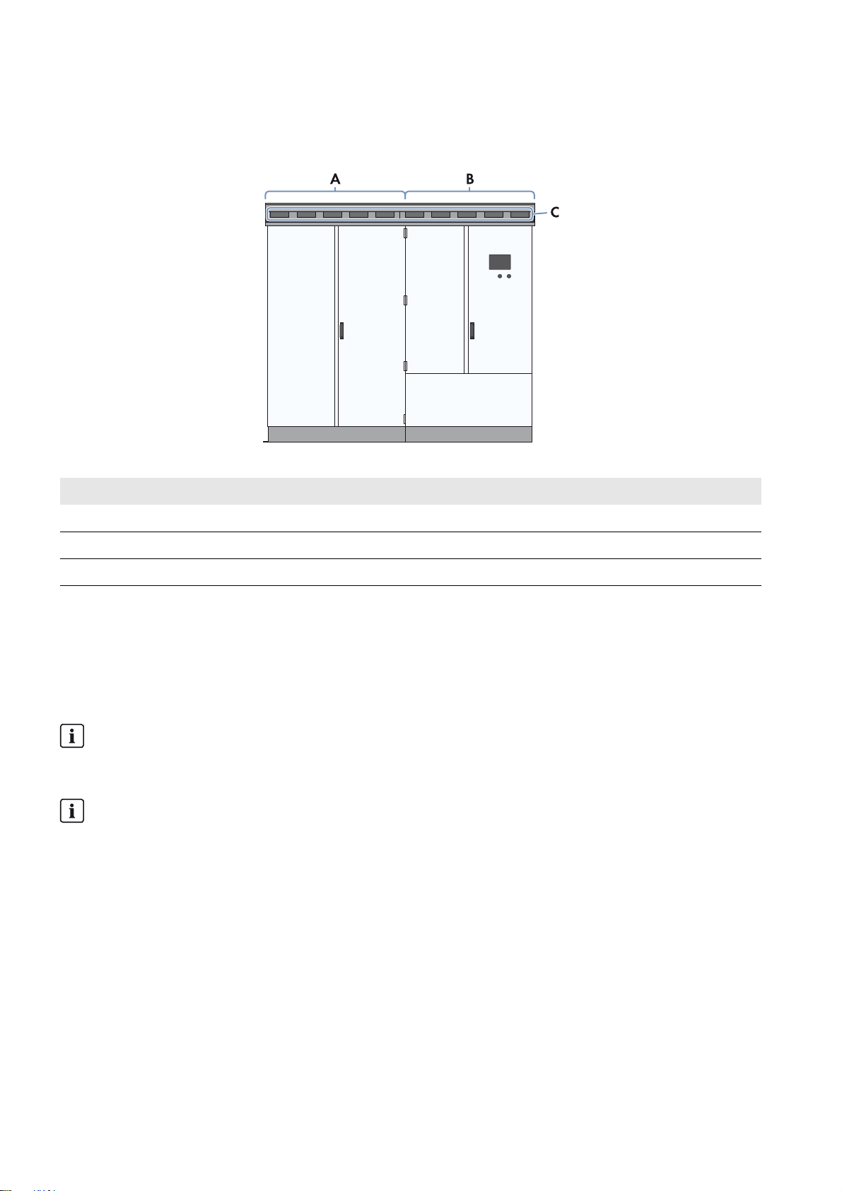
3.1 Design of the Inverter
Figure1: Design of the inverter
Position Designation
A Inverter cabinet
B Interface cabinet
C Ventilation grid
3.2 Type Label
The type label clearly identifies the product. There is one type label present in the Sunny Central. The type label is located
in the right-hand top corner inside the interface cabinet.
You will require the information on the type label to use the product safely and when seeking customer support from the
SMA Service Line. The type labels must be permanently attached to the product.
Reading off the serial number
You can read off the serial number without opening the inverter. The serial number can be found on the roof of the
inverter at the top left. You can also read off the serial number from the touch display.
Reading off the firmware version
You can read the version number of the firmware from the inverter and the touch display via the user interface of the
inverter or on the touch display.
12 SCCP-JP-WA-A4-en-12 Maintenance Manual
SMA Solar Technology AG 4 Maintenance Intervals
4 Maintenance Intervals
Shorter maintenance intervals in the event of adverse ambient conditions
The location of the PV system and ambient conditions influence the maintenance intervals.
• If the inverter is installed in adverse ambient conditions, SMA recommends a monthly inspection in order to
determine the need for maintenance. The maintenance intervals are to be shortened depending on the
determined maintenance requirements. In particular, cleaning work and corrosion protection may be necessary
more frequently.
• Adherence to the maintenance intervals ensures trouble-free operation of the inverter (see the maintenance
report of the inverter).
Maintenance under normal ambient and operating conditions:
Description Interval
Routine maintenance Every 24 months
Preventive replacement intervals:
Description Interval
Replacement of 24 V power supply units*
Replacement of inverter bridge fan* Every 13 years**
Replacement of interior fans* Every 13 years**
GFDI / ABB high-performance circuit breaker* After 100 trippings due to short circuit or after 7,000
Remote Switch Unit of the GFDI* After 7,000 switching cycles***
GFDI auxiliary signal contact* Every six years
Surge arrester If tripped
Key switch In case of severe signs of wear
Label on the enclosure If illegible, defective or missing
* Contact the SMA Service Line.
** For option "Q at Night", the replacement intervals are halved.
*** The trippings and switching cycles are recorded as instantaneous values (see Section5.1 "Reading off the Replacement Interval Meter",
page14).
Every ten years
switching cycles***
Spare Parts
Spare parts can be identified via their reference designation and the circuit diagram. The spare parts list includes the
article numbers of each spare part. For information on a specific article number, contact the SMA Service Line.
Maintenance Manual SCCP-JP-WA-A4-en-12 13
5 Maintenance under Voltage Conditions SMA Solar Technology AG
'$1*(5
5 Maintenance under Voltage Conditions
5.1 Reading off the Replacement Interval Meter
1. Log into the user interface.
2. Enter the password in the appropriate field on the homepage and confirm with [Login].
3. Select Data > Device.
4. Select .
☑ A list of all existing device types appears.
5. Select the device type Sunny Central.
☑ A list appears containing all existing devices of this type.
6. Select the desired device from the list.
7. Select the tab Instantaneous values.
8. Check the following meters and compare them with the replacement intervals (see Section4, page13):
– Number of GFDI trippings in the instantaneous value CntGfdiTripSw. If replacement of the GFDI is necessary,
the error message 7714 will appear on the display.
– Number of switching cycles of the Remote Switch Unit of the GFDI in the instantaneous value CntGfdiSw
9. If the corresponding instantaneous value is equal to or greater than the replacement interval of the device, replace
the device. Contact the SMA Service Line.
5.2 Reading off Error Messages and Warnings
You can connect a computer via the service interface on the outside of the interface cabinet.
If an error occurs, read off and resolve the error using the display or the user interface on the inverter (see Sunny Central
operating manual).
5.3 Checking the DC Load-Break Switch
Danger to life from electric shock due to live voltage
High voltages are present in the live components of the Sunny Central. Touching live components results in death or
serious injury due to electric shock.
• When working in a high contact-risk environment, wear personal protective equipment.
• All work must be carried out in accordance with this document. Observe all safety precautions. Observe all safety
precautions included in this document and the inverter installation manual.
• Do not touch any live components of the inverter or the medium-voltage grid. Comply with all applicable safety
regulations for handling medium-voltage grids.
14 SCCP-JP-WA-A4-en-12 Maintenance Manual
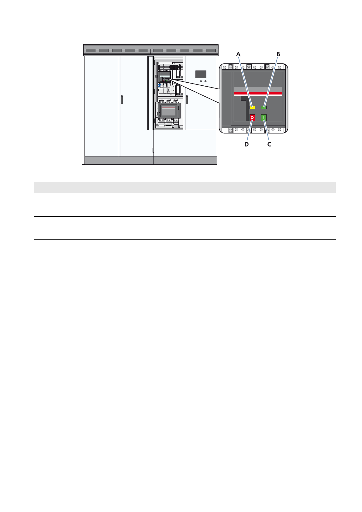
SMA Solar Technology AG 5 Maintenance under Voltage Conditions
Figure2: Indicators and switches on the DC load-break switch
Position Designation
A Spring status indicator
B Position indicator
C ON button
D OFF button
Requirements:
☐ Control voltage is present.
☐DC voltage is present.
Procedure:
1. Switch the inverter to Stop.
2. Open the doors of the interface cabinet.
3. Check whether the DC load-break switch is switched off and is indicating the Off position.
If the DC load-break switch is not switched off or indicating the Off position, contact the SMA Service Line.
4. Close the doors of the interface cabinet.
5. Switch the inverter to Start.
6. Open the doors of the interface cabinet.
7. Check whether the DC load-break switch is switched on and or indicating the On position.
If the DC load-break switch is not switched on or indicating the On position, contact the SMA Service Line.
8. Switch the inverter to Stop.
9. Close the doors of the interface cabinet.
Maintenance Manual SCCP-JP-WA-A4-en-12 15
5 Maintenance under Voltage Conditions SMA Solar Technology AG
5.4 AC Circuit Breaker (Optional)
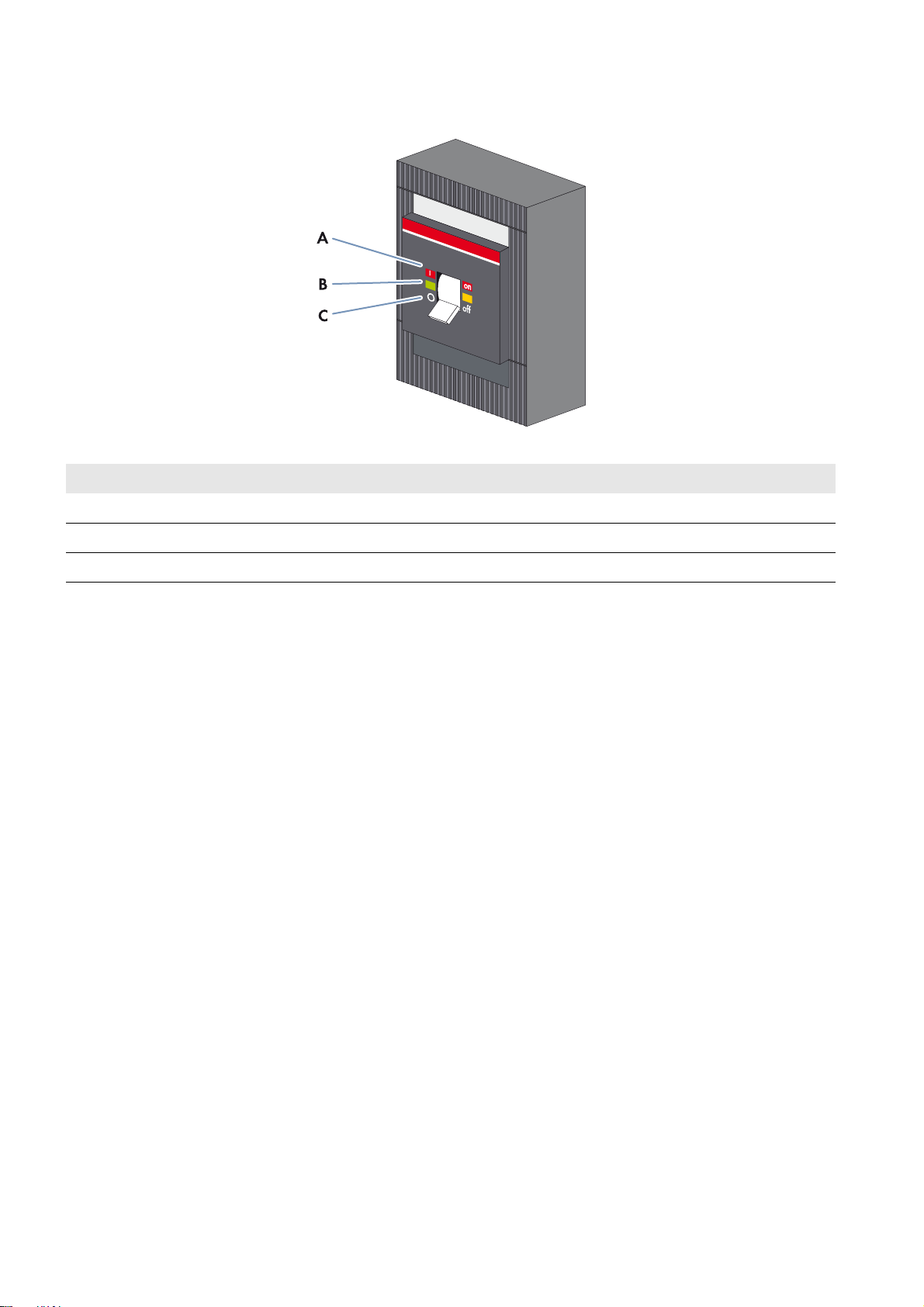
Figure3: Switch positions of the AC circuit breaker
Position Designation
A Off position
B Triggered position
C On position
Additionally required maintenance material (not included in the scope of delivery):
☐ A testing device approved by the manufacturer of the AC circuit breaker, e.g. TT1 from ABB.
Procedure:
• Use the testing device to check whether the AC circuit breaker is ready for operation (instructions for testing are
included in the documentation of the testing device).
If the AC circuit breaker is not ready for operation, contact the SMA Service Line.
16 SCCP-JP-WA-A4-en-12 Maintenance Manual
 Loading...