

Page 1
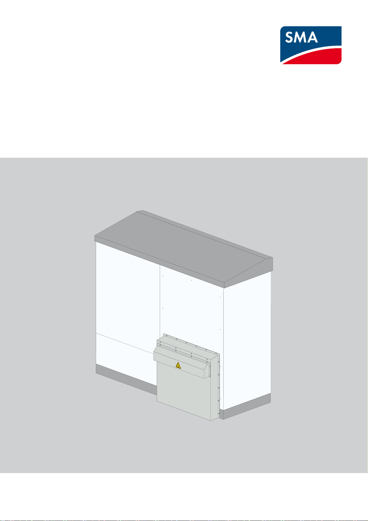
Mounting Instructions for Retrofitting
Noise Reduction
SUNNY CENTRAL 500CP-JP / 630CP-JP / 800CP-JP
SCCP-JP-MA-Silence-en-10 | 98-114400.01 | Version 1.0 ENGLISH
Page 2

Legal Provisions SMA Solar Technology AG
Legal Provisions
The information contained in this document is the property of SMA Solar Technology AG. Publishing its content, either
partially or in full, requires the written permission of SMA Solar Technology AG. Any internal company copying of the
document for the purposes of evaluating the product or its correct implementation is allowed and does not require
permission.
SMA Warranty
You can download the current warranty conditions from the Internet at www.SMA-Solar.com.
Trademarks
All trademarks are recognized, even if not explicitly identified as such. A lack of identification does not mean that a
product or symbol is not trademarked.
The Bluetooth
by SMA Solar Technology AG is under license.
Modbus
QR Code is a registered trademark of DENSO WAVE INCORPORATED.
Phillips
®
is a registered trademark of Acument Global Technologies, Inc.
Torx
®
word mark and logos are registered trademarks owned by Bluetooth SIG, Inc. and any use of these marks
®
is a registered trademark of Schneider Electric and is licensed by the Modbus Organization, Inc.
®
and Pozidriv® are registered trademarks of Phillips Screw Company.
SMA Solar Technology AG
Sonnenallee 1
34266 Niestetal
Germany
Tel. +49 561 9522-0
Fax +49 561 9522-100
www.SMA.de
E-mail: info@SMA.de
© 2004 to 2014 SMA Solar Technology AG. All rights reserved
2 SCCP-JP-MA-Silence-en-10 Mounting Instructions
Page 3

SMA Solar Technology AG Table of Contents
Table of Contents
1 Information on this Document. . . . . . . . . . . . . . . . . . . . . . . . . . . . . . . . . . . . . . . . . . . . . . . . . . . . . 4
2 Safety . . . . . . . . . . . . . . . . . . . . . . . . . . . . . . . . . . . . . . . . . . . . . . . . . . . . . . . . . . . . . . . . . . . . . . . . 5
2.1 Intended Use . . . . . . . . . . . . . . . . . . . . . . . . . . . . . . . . . . . . . . . . . . . . . . . . . . . . . . . . . . . . . . . . . . . . . . . . . 5
2.2 Safety Precautions . . . . . . . . . . . . . . . . . . . . . . . . . . . . . . . . . . . . . . . . . . . . . . . . . . . . . . . . . . . . . . . . . . . . . 6
2.3 Skills of Qualified Persons . . . . . . . . . . . . . . . . . . . . . . . . . . . . . . . . . . . . . . . . . . . . . . . . . . . . . . . . . . . . . . . 8
2.4 Personal Protective Equipment . . . . . . . . . . . . . . . . . . . . . . . . . . . . . . . . . . . . . . . . . . . . . . . . . . . . . . . . . . . . 8
3 Product Description . . . . . . . . . . . . . . . . . . . . . . . . . . . . . . . . . . . . . . . . . . . . . . . . . . . . . . . . . . . . . 9
3.1 SunnyCentral . . . . . . . . . . . . . . . . . . . . . . . . . . . . . . . . . . . . . . . . . . . . . . . . . . . . . . . . . . . . . . . . . . . . . . . . . 9
3.1.1 Front View of the Sunny Central . . . . . . . . . . . . . . . . . . . . . . . . . . . . . . . . . . . . . . . . . . . . . . . . . . . . . . . . . . . . .9
3.1.2 Rear View of the Sunny Central. . . . . . . . . . . . . . . . . . . . . . . . . . . . . . . . . . . . . . . . . . . . . . . . . . . . . . . . . . . . . .9
3.1.3 Type Label . . . . . . . . . . . . . . . . . . . . . . . . . . . . . . . . . . . . . . . . . . . . . . . . . . . . . . . . . . . . . . . . . . . . . . . . . . . . .10
4 Scope of Delivery. . . . . . . . . . . . . . . . . . . . . . . . . . . . . . . . . . . . . . . . . . . . . . . . . . . . . . . . . . . . . . 11
4.1 Scope of DeliveryScope of Delivery - Silencing Baffle . . . . . . . . . . . . . . . . . . . . . . . . . . . . . . . . . . . . . . . . . 11
4.2 Scope of Delivery - Kick Plate Set and Rear Panel . . . . . . . . . . . . . . . . . . . . . . . . . . . . . . . . . . . . . . . . . . . . 12
5 Preparations for Assembly . . . . . . . . . . . . . . . . . . . . . . . . . . . . . . . . . . . . . . . . . . . . . . . . . . . . . . 13
5.1 Additionally Required Mounting Material . . . . . . . . . . . . . . . . . . . . . . . . . . . . . . . . . . . . . . . . . . . . . . . . . . 13
5.2 Disconnecting the Inverter. . . . . . . . . . . . . . . . . . . . . . . . . . . . . . . . . . . . . . . . . . . . . . . . . . . . . . . . . . . . . . . 13
6 Assembly . . . . . . . . . . . . . . . . . . . . . . . . . . . . . . . . . . . . . . . . . . . . . . . . . . . . . . . . . . . . . . . . . . . . 14
6.1 Disassembling the Kick Plates. . . . . . . . . . . . . . . . . . . . . . . . . . . . . . . . . . . . . . . . . . . . . . . . . . . . . . . . . . . . 14
6.2 Removing the Existing Ventilation Plate. . . . . . . . . . . . . . . . . . . . . . . . . . . . . . . . . . . . . . . . . . . . . . . . . . . . . 15
6.3 Disassembling the Rear Panel. . . . . . . . . . . . . . . . . . . . . . . . . . . . . . . . . . . . . . . . . . . . . . . . . . . . . . . . . . . . 16
6.4 Mounting the New Rear Panel . . . . . . . . . . . . . . . . . . . . . . . . . . . . . . . . . . . . . . . . . . . . . . . . . . . . . . . . . . . 17
6.5 Mounting the Kick Plate for the Sound Absorber . . . . . . . . . . . . . . . . . . . . . . . . . . . . . . . . . . . . . . . . . . . . . 19
6.6 Mounting the Ventilation Plate . . . . . . . . . . . . . . . . . . . . . . . . . . . . . . . . . . . . . . . . . . . . . . . . . . . . . . . . . . . 19
6.7 Mounting the Kick Plates . . . . . . . . . . . . . . . . . . . . . . . . . . . . . . . . . . . . . . . . . . . . . . . . . . . . . . . . . . . . . . . 19
6.8 Mounting the Silencing Baffle. . . . . . . . . . . . . . . . . . . . . . . . . . . . . . . . . . . . . . . . . . . . . . . . . . . . . . . . . . . . 19
7 Switching the Inverter On . . . . . . . . . . . . . . . . . . . . . . . . . . . . . . . . . . . . . . . . . . . . . . . . . . . . . . . 23
8 Dimensions of the Sunny Central . . . . . . . . . . . . . . . . . . . . . . . . . . . . . . . . . . . . . . . . . . . . . . . . . 24
8.1 Minimum Clearances . . . . . . . . . . . . . . . . . . . . . . . . . . . . . . . . . . . . . . . . . . . . . . . . . . . . . . . . . . . . . . . . . . 24
9 Technical Data . . . . . . . . . . . . . . . . . . . . . . . . . . . . . . . . . . . . . . . . . . . . . . . . . . . . . . . . . . . . . . . . 27
9.1 Sunny Central 500CP‑JP. . . . . . . . . . . . . . . . . . . . . . . . . . . . . . . . . . . . . . . . . . . . . . . . . . . . . . . . . . . . . . . . 27
9.2 Sunny Central 630CP-JP. . . . . . . . . . . . . . . . . . . . . . . . . . . . . . . . . . . . . . . . . . . . . . . . . . . . . . . . . . . . . . . . 29
9.3 Sunny Central 800CP-JP. . . . . . . . . . . . . . . . . . . . . . . . . . . . . . . . . . . . . . . . . . . . . . . . . . . . . . . . . . . . . . . . 31
10 Contact . . . . . . . . . . . . . . . . . . . . . . . . . . . . . . . . . . . . . . . . . . . . . . . . . . . . . . . . . . . . . . . . . . . . . . 34
Mounting Instructions SCCP-JP-MA-Silence-en-10 3
Page 4
1 Information on this Document SMA Solar Technology AG
'$1*(5
:$5 1,1*
&$87,21
/05*$&
1 Information on this Document
Validity
This document describes actions and adjustments designed to achieve a reduction in the noise emission of the inverter
and is valid for the following device types from production version A1:
• SC 500CP-10-JP (Sunny Central 500CP-JP)
• SC 630CP-10-JP (Sunny Central 630CP-JP)
• SC 800CP-10-JP (Sunny Central 800CP-JP)
The production version is indicated on the type label.
This document is a supplement to the documentation supplied with the product. Only full and complete documentation
will ensure that all the relevant information is available.
Illustrations in this document are reduced to the essential and may deviate from the real product.
Target Group
This document is intended for qualified persons. Only persons with the appropriate skills are allowed to perform the tasks
described in this document (see Section2.3 "Skills of Qualified Persons", page8).
Symbols
Symbol Explanation
Indicates a hazardous situation which, if not avoided, will result in death or serious injury
Indicates a hazardous situation which, if not avoided, can result in death or serious injury
Indicates a hazardous situation which, if not avoided, can result in minor or moderate injury
Indicates a situation which, if not avoided, can result in property damage
Information that is important for a specific topic or goal, but is not safety-relevant
☐ Indicates a requirement for meeting a specific goal
☑ Desired result
✖ A problem that might occur
4 SCCP-JP-MA-Silence-en-10 Mounting Instructions
Page 5

SMA Solar Technology AG 2 Safety
2 Safety
2.1 Intended Use
The Sunny Central is a PV inverter which converts the direct current generated in the PV modules into grid-compliant
alternating current. An external MV transformer fitted downstream feeds the generated alternating current into the utility
grid.
The Sunny Central is suitable for outdoor installation provided that the specified safety distances are maintained.
The enclosure conforms with degree of protection IP54. IP54 means that when the Sunny Central is closed, it is protected
against splashing water from all angles and against interior dust deposits. The Sunny Central is classified under
Class 4C2 according to EN 60721-3-4 and is suitable for operation in a chemically active environment.
The maximum permissible DC input voltage of the Sunny Central must not be exceeded.
The Sunny Central must only be operated in conjunction with a suitable MV transformer. The MV transformer must be
designed for voltages that arise during pulsed mode of the Sunny Central. The maximum AC voltages can reach the
following magnitudes to ground:
• For inverter type SC 500CP-JP, voltages of max. ±800 V to ground.
• For inverter type SC 630CP-JP, voltages of max. ±1,450 V to ground.
• For inverter type SC 800CP-JP, voltages of max. ±1,450 V to ground.
Do not deactivate or adjust settings that affect grid management services without first obtaining approval from the grid
operator.
Alterations to the product, e.g. changes or modifications, are only permitted with the express written permission of
SMA Solar Technology AG. Making unauthorized changes will void the warranty and is likely to result in invalidation of
the operating permit. SMA Solar Technology AG shall not be held liable for any damage caused by such changes.
Use the Sunny Central in strict accordance with the information provided in the enclosed documentation. Any other
application may cause personal injury or property damage.
The enclosed documentation is an integral part of this product.
• Read and observe the documentation.
• Keep the documentation in a convenient place for future reference.
Mounting Instructions SCCP-JP-MA-Silence-en-10 5
Page 6
2 Safety SMA Solar Technology AG
'$1*(5
2.2 Safety Precautions
This section contains safety precautions that must be observed at all times when working on or with the product.
To prevent personal injury and property damage and to ensure long-term operation of the product, read this section
carefully and follow all safety precautions at all times.
Danger to life from electric shock due to live voltage
High voltages are present in the live components of the Sunny Central. Touching live components results in death or
serious injury due to electric shock.
• When working in a high contact-risk environment, wear personal protective equipment.
• Do not touch any live components.
• Follow the instructions precisely.
• Observe all warning messages on the product and in the documentation.
• Observe all safety precautions of the module manufacturer.
• Provided live voltage is not absolutely necessary, always disconnect the following components from voltage
sources before performing any work on the inverter:
– Grid voltage for grid feed-in
– Internal power supply
– DC voltage from the PV array
– Additional external voltages, e.g. control signals from a control room
• Ensure that no disconnected components can be reconnected.
• After disconnecting the Sunny Central from voltage sources, wait at least 15 minutes for the capacitors of the
Sunny Central to discharge completely.
• Before working on the Sunny Central, check that all devices are completely voltage-free.
• Ground and short-circuit.
• Cover or isolate any adjacent live components.
Danger to life from electric shock due to live DC cables
DC cables connected to PV modules that are exposed to sunlight carry live voltage. Touching live components results
in death or serious injury.
• Wear suitable personal protective equipment for all work on the Sunny Central.
• Prior to connecting the DC cables, ensure that the DC cables are voltage-free.
Danger to life from electric shock due to ground fault
If a ground fault has occurred, parts of the PV system that are supposedly grounded may in fact be live.
Touching incorrectly grounded components results in death or serious injuries from electric shock.
• Ensure that no voltage is present before touching any components of the PV system.
• Wear suitable personal protective equipment for all work on the Sunny Central.
6 SCCP-JP-MA-Silence-en-10 Mounting Instructions
Page 7
SMA Solar Technology AG 2 Safety
:$5 1,1*
&$87,21
/05*$&
Danger to life due to blocked escape routes
In hazardous situations, blocked escape routes can lead to death or serious injury. Opening the doors of two
Sunny Central inverters located opposite each other blocks the escape route. It is imperative that the escape route is
freely accessible at all times.
• An escape route of at least 500 mm width must be available at all times. Make sure the minimum passage width
of the escape route meets local standards.
• Do not place any objects in the escape route area.
• Remove all tripping hazards from escape routes.
• If two Sunny Central inverters have been installed facing each other, never open the doors of both inverters
simultaneously.
Risk of burns due to hot components
Some components of the Sunny Central can get very hot during operation. Touching these components can cause
burns.
• Observe the warning messages on the devices.
• During operation, do not touch any components marked with such warnings.
• After disconnecting the plant from voltage sources, wait until any hot components have cooled down sufficiently.
• Wear suitable personal protective equipment for all work on the Sunny Central.
Damage to the devices due to dust or moisture penetration
Dust or moisture penetration can damage the Sunny Central or impair its functionality.
• Do not open the Sunny Central during rainfall or humidity of more than 95%.
• Only service the Sunny Central when the environment is dry and free of dust.
• Do not operate the Sunny Central with the door open.
• Do not connect the external supply voltage before the Sunny Central has been mounted and installed.
• Switch on the circuit breaker for external supply voltage. This will activate the heating element and internal fans so
that they can switch on automatically when needed.
• If the installation or commissioning process is interrupted, mount all the panels of the Sunny Central.
• Close and lock the Sunny Central.
Damage to electronic components due to electrostatic discharge
Electrostatic discharge can damage or destroy electronic components.
• Observe the ESD safety regulations when working on the device.
• Wear suitable personal protective equipment for all work on the device.
• Discharge electrostatic charge by touching uncoated, grounded enclosure parts (e.g. near the grounding
connection on the doors). Only then is it safe to touch electronic components.
Mounting Instructions SCCP-JP-MA-Silence-en-10 7
Page 8

2 Safety SMA Solar Technology AG
2.3 Skills of Qualified Persons
The tasks described in this manual must be performed by qualified persons only. Qualified persons must have the
following skills:
• Knowledge of how a Sunny Central works and is operated
• Training in how to deal with the dangers and risks associated with installing and using electrical devices and systems
• Training in the installation and commissioning of electrical devices and systems
• Knowledge of all applicable standards and directives
• Knowledge of and adherence to this manual and all safety precautions
2.4 Personal Protective Equipment
Always wear suitable protective equipment
When working on the Sunny Central, always wear the appropriate personal protective equipment for the specific
job.
The following personal protective equipment is regarded by SMA Solar Technology AG to be the minimum requirement:
☐ In a dry environment, safety shoes of category S3 with perforation-proof soles and steel toe caps
☐ During precipitation or on moist ground, safety boots of category S5 with perforation-proof soles and steel toe caps
☐ Tight-fitting work clothes made of 100% cotton
☐ Suitable work pants
☐ Individually fitted hearing protection
☐Safety gloves
Any other prescribed protective equipment must also be used.
8 SCCP-JP-MA-Silence-en-10 Mounting Instructions
Page 9
SMA Solar Technology AG 3 Product Description
3 Product Description
3.1 SunnyCentral
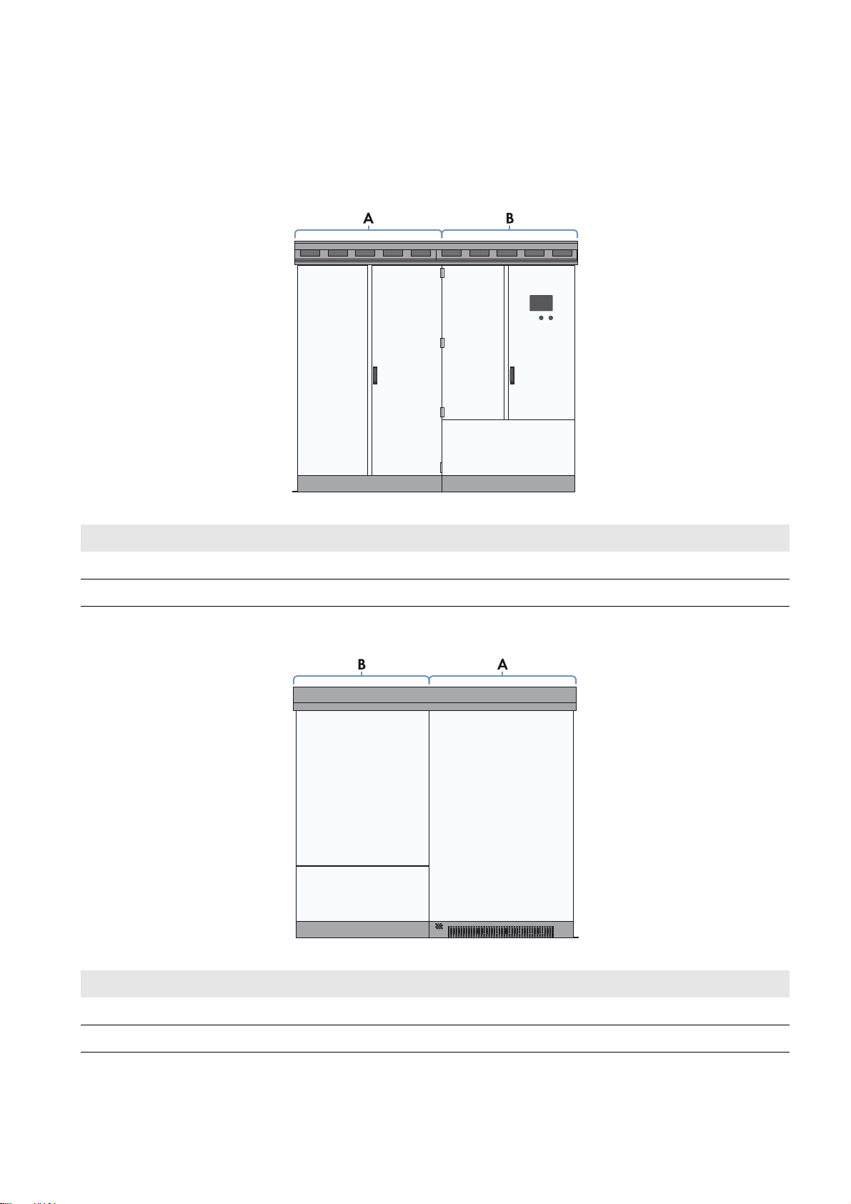
3.1.1 Front View of the Sunny Central
Figure1: Sunny Central front view
Position Designation
A Inverter cabinet
B Interface cabinet
3.1.2 Rear View of the Sunny Central
Figure2: Sunny Central rear view
Position Designation
A Inverter cabinet
B Interface cabinet
Mounting Instructions SCCP-JP-MA-Silence-en-10 9
Page 10

3 Product Description SMA Solar Technology AG
3.1.3 Type Label
The type label clearly identifies the product. Two type labels are present on the Sunny Central. The type labels are
positioned in the inverter cabinet to the left of the air duct and in the interface cabinet on the left side of the enclosure.
You will require the information on the type label to use the product safely and when seeking customer support from the
SMA Service Line. The type labels must be permanently attached to the product.
Reading off the serial number
You can identify the serial number without opening the Sunny Central. The serial number is located on the top left
corner of the Sunny Central roof. You can also read off the serial number from the touch display.
Reading off the firmware version
You can read off the version number of the Sunny Central and touch display firmware via the user interface.
You can also read off the version number of the touch display firmware on the touch display.
10 SCCP-JP-MA-Silence-en-10 Mounting Instructions
Page 11
SMA Solar Technology AG 4 Scope of Delivery
4 Scope of Delivery
Check the scope of delivery for completeness and any externally visible damage. Contact your distributor if the scope of
delivery is incomplete or damaged.
The scope of delivery comprises two boxes and the rear panel of the inverter. The individual parts included in the delivery
are listed below.
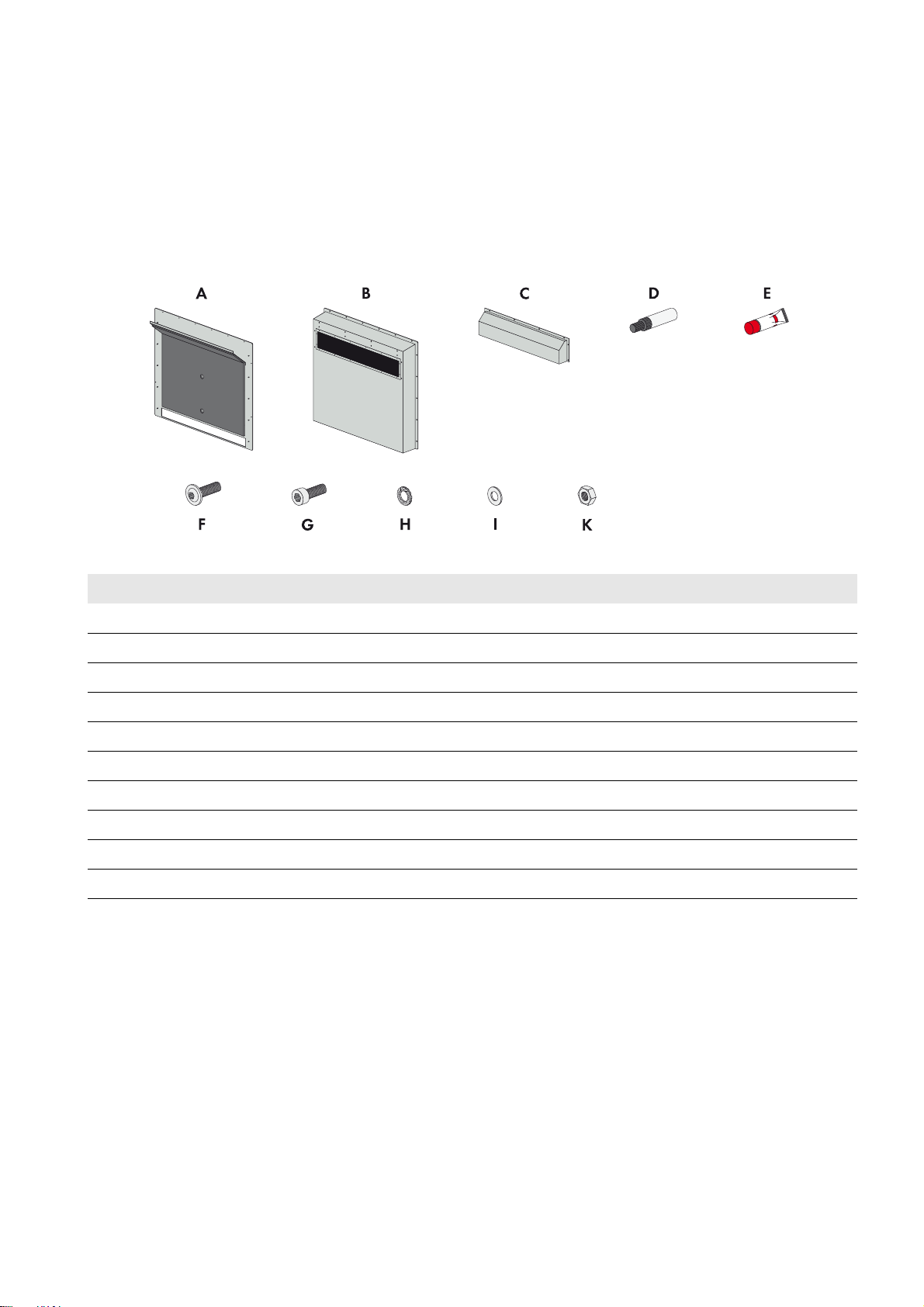
4.1 Scope of DeliveryScope of Delivery - Silencing Baffle
Figure3: Components included in the scope of delivery of the silencing baffle
Position Quantity Designation
A 1 Silencing baffle rear panel, including ventilation plate
B 1 Silencing baffle lid
C1Rain protection
D 1 Touch-up stick RAL 7035
E1OKS
F 15 Pan head flange screw
G 9 Cylinder head screw
H7Contact washer
I14Washer
K10Hexagon nut
®
250 allround paste
Mounting Instructions SCCP-JP-MA-Silence-en-10 11
Page 12

4 Scope of Delivery SMA Solar Technology AG
4.2 Scope of Delivery - Kick Plate Set and Rear Panel
Figure4: Components included in the scope of delivery of the kick plate set
Position Quantity Designation
A 1 Inverter rear panel
B 1 Kick plate set including soundproofing material
C 1 Ventilation plate
D1OKS
®
250 allround paste
E 9 Countersunk screw
12 SCCP-JP-MA-Silence-en-10 Mounting Instructions
Page 13

SMA Solar Technology AG 5 Preparations for Assembly
'$1*(5
5 Preparations for Assembly
Provide storage facilities prior to the start of assembly work
Storage facilities for the enclosure parts must be provided prior to the start of the assembly work. Make sure that the
enclosure parts, seals and screws are not damaged during storage.
5.1 Additionally Required Mounting Material
The tools and materials indicated in this section must be provided by the customer.
The following tools and materials are required for the assembly work:
☐ Torque wrench with TX attachment (TX 30)
☐ Torx screwdriver (TX 30)
☐ Storage location for enclosure parts (e.g. padded storage cart)
☐ Torque wrench (socket wrench size 13)
5.2 Disconnecting the Inverter
Danger to life from electric shock due to live voltage
High voltages are present in the inverter and its components. Touching live components results in death or serious injury
due to electric shock.
• Wear suitable personal protective equipment for all work on the Sunny Central.
• Switch the inverter off (see inverter installation manual).
• After switching off the inverter, wait at least 15 minutes until the inverter capacitors have discharged completely.
• Disconnect the inverter from voltage sources (see inverter installation manual).
Mounting Instructions SCCP-JP-MA-Silence-en-10 13
Page 14

6 Assembly SMA Solar Technology AG
/05*$&
/05*$&
6 Assembly
Damage to the inverter through moisture or dust intrusion
During assembly work, the inverter is not sufficiently protected against dust and moisture. If the assembly work is carried
out during rainfall or in a dusty environment, moisture or dust can penetrate the inverter. This can damage the electronic
components or impair the functionality of the inverter.
• Make sure that no dust, moisture or foreign bodies are present in the inverter after assembly.
Damage to the inverter due to improper storage of the enclosure parts
Seals are to be found on the rear side of the enclosure parts. If the enclosure parts are not stored properly, these seals
may be damaged. If seals are damaged, this will compromise the weatherproof seal of the inverter. Dust and moisture
can penetrate the inverter.
• Store the enclosure parts properly.
• Replace damaged seals.
Take weather conditions into account
Before starting the assembly work, ensure that the weather conditions are suitable for opening the inverter. If this is
not the case, you must take appropriate measures to protect the inverter from inclement weather.
6.1 Disassembling the Kick Plates
The kick plates are mounted at the bottom front and rear of the inverter.
Figure5: Position of the kick plates
Position Designation
A Front kick plate on the inverter
B Rear kick plate on the inverter
Requirement:
☐ The additionally required mounting material must be available (see Section5.1 "Additionally Required Mounting
Material", page13).
14 SCCP-JP-MA-Silence-en-10 Mounting Instructions
Page 15

SMA Solar Technology AG 6 Assembly
'$1*(5
Procedure:
1.
Danger to life from electric shock due to live voltage
Prior to performing any work on the inverter, disconnect it from voltage sources (see inverter installation manual).
2. Remove all screws from the kick plates using a suitable screwdriver. Screwdriver: TX 30
3. Remove the four screws on each of the two front kick plates. Retain the screws for subsequent mounting of the new
kick plates.
4. Remove both front kick plates.
5. Remove the four screws on each of the two rear kick plates. Retain the screws for subsequent mounting of the new
kick plates.
6. Remove both rear kick plates.
7. Dispose of the kick plates.
6.2 Removing the Existing Ventilation Plate
1. Pull the ventilation plate forwards out of the base area of the inverter
cabinet. Grasp underneath the ventilation plate and press the
middle part up while pulling it out.
2. Dispose of the ventilation plate.
Mounting Instructions SCCP-JP-MA-Silence-en-10 15
Page 16

6 Assembly SMA Solar Technology AG
&$87,21
'$1*(5
6.3 Disassembling the Rear Panel
Figure6: Illustration of the rear panel to be disassembled
Requirements:
☐ Two persons must be available for disassembling the rear panel.
☐ The required mounting material must be available.
☐ A storage location for the enclosure parts must be available.
☐ The inverter must be sufficiently protected from inclement weather.
Danger of crushing caused by heavy, bulky rear panel
The rear panel of the inverter weighs up to 20 kg. If the rear panel slips or jams, limbs could be crushed.
• Always have two persons available for assembling and disassembling the enclosure parts.
• When carrying out any work on the inverter, always wear suitable personal protective equipment.
Procedure:
1.
Danger to life from electric shock due to live voltage
Prior to performing any work on the inverter, disconnect it from voltage sources (see inverter installation manual).
2. Secure the rear panel of the inverter from slipping off.
3. Unscrew all ten screws of the rear panel using a suitable
screwdriver. Screwdriver: TX 30
4. Remove all screws from the rear panel and retain for later use.
16 SCCP-JP-MA-Silence-en-10 Mounting Instructions
Page 17

SMA Solar Technology AG 6 Assembly
/05*$&
&$87,21
5. Carefully pull the rear panel of the inverter cabinet approx. 80 mm
to 100 mm towards you. Make sure that the hook fitting cannot fall
out.
6.
Property damage due to grounding cable being ripped out
The rear panel of the inverter and the switch cabinet are connected
via a grounding cable. If the rear panel is removed without due
care, the grounding cable could be ripped off and the inverter
damaged.
• Use a suitable wrench to release the grounding cable from the
rear panel before removing the rear panel. Wrench size:
AF 13
7. Remove the rear panel and store it.
6.4 Mounting the New Rear Panel
Requirements:
☐ The required mounting material must be available (see Section5.1 "Additionally Required Mounting Material",
page13).
☐ The inverter must be sufficiently protected from inclement weather.
☐ Two persons must be available for assembling the rear panel.
Danger of crushing caused by heavy, bulky rear panel
The rear panel of the inverter weighs up to 20 kg. If the rear panel slips or jams, limbs could be crushed.
• Always have two persons available for assembling and disassembling the enclosure parts.
• When carrying out any work on the inverter, always wear suitable personal protective equipment.
Mounting Instructions SCCP-JP-MA-Silence-en-10 17
Page 18

6 Assembly SMA Solar Technology AG
Procedure:
1. Position the new rear panel in front of the inverter opening and
ensure that it cannot tip over.
2. Apply metal-free allround paste to the rear-panel bolt for mounting the grounding cable.
3. Fasten the grounding cable to the rear-panel bolt using a suitable
torque wrench (torque: 6 Nm).
4. Ensure that the grounding cable is correctly mounted.
5. Hook the rear panel into the hook fitting.
6. Apply metal-free allround paste to all threads and set screws.
7. Align the rear panel on the inverter.
8. Insert the five upper screws of the rear panel into the threads and
tighten (torque: 8 Nm).
9. Make sure that the rear panel is correctly mounted.
18 SCCP-JP-MA-Silence-en-10 Mounting Instructions
Page 19

SMA Solar Technology AG 6 Assembly
6.5 Mounting the Kick Plate for the Sound Absorber
1. Apply metal-free allround paste to all threads in the base area.
2. Position and align the kick plate for the sound absorber on the
enclosure.
3. Screw pan head flange screws into the threads.
4. Tighten the pan head flange screws on the kick plate with a suitable screwdriver (torque: 8 Nm)
6.6 Mounting the Ventilation Plate
The guide rails for the ventilation plate are located in the floor area of the inverter cabinet.
Procedure:
• Slide the ventilation plate into the guide rails in the inverter cabinet from the front. The ventilation grid in the
ventilation plate should be facing the rear panel.
☑ The ventilation plate is flush with the Sunny Central.
✖ The ventilation plate will not go all the way in?
• Grip the ventilation plate from underneath and press the middle part upwards while sliding it in.
6.7 Mounting the Kick Plates
1. Position and align the kick plates with soundproofing material on the enclosure.
2. Screw the previously retained pan head flange screws into the threads.
3. Tighten the pan head flange screws on the kick plate with a suitable screwdriver (torque: 8 Nm)
6.8 Mounting the Silencing Baffle
Procedure:
To mount the silencing baffle, perform the following actions in the specified order. The exact procedure is described in
the steps below.
• Mounting the rear panel of the silencing baffle
• Mounting the lid of the silencing baffle
• Mounting the rain protection
Mounting the Rear Panel of the Silencing Baffle
Required mounting material:
☐ 2 cylinder head screws
☐2 contact washers
Mounting Instructions SCCP-JP-MA-Silence-en-10 19
Page 20

6 Assembly SMA Solar Technology AG
Procedure:
1. Align the rear panel of the silencing baffle on the rear panel of the
inverter.
2. Insert two cylinder head screws with contact washers into the
middle threads of the rear panel. The rear panel of the silencing
baffle should still be loose.
Mounting the Lid of the Silencing Baffle
Required mounting material:
☐ 1 cylinder head screw
☐ 3 contact washers
☐ 9 pan head flange screws
☐ 13 washers
☐ 10 hexagon nuts
Procedure:
1. Align the lid on the rear panel. The lid should be over the stud bolts.
2. Insert a cylinder head screw with contact washer into the top left
thread. Do not tighten the screw yet.
20 SCCP-JP-MA-Silence-en-10 Mounting Instructions
Page 21

SMA Solar Technology AG 6 Assembly
3. Insert five pan head flange screws into the upper threads of the lid.
Do not tighten the screws yet.
4. Fasten the ventilation plate on the rear panel of the silencing baffle
to the lid. Do not tighten the five pan head flange screws yet.
5. Screw two hexagon nuts with contact washers onto the bottom
right and left stud bolts of the rear panel.
6. Screw all hexagon nuts and washers onto the remaining stud bolts
of the rear panel.
7. Align the lid and tighten all bolts and nuts (torque: 8 Nm).
Mounting Instructions SCCP-JP-MA-Silence-en-10 21
Page 22

6 Assembly SMA Solar Technology AG
Mounting the Rain Protection
Required mounting material:
☐ 2 cylinder head screws
☐ 2 contact washers
☐ 6 pan head flange screws
Procedure:
1. Align the rain protection on the silencing baffle.
2. Screw two cylinder head screws with contact washers into the
bottom right and left threads of the lid and tighten (torque: 8 Nm).
3. Insert six pan head flange screws into the threads and tighten
(torque: 8 Nm).
22 SCCP-JP-MA-Silence-en-10 Mounting Instructions
Page 23

SMA Solar Technology AG 7 Switching the Inverter On
7 Switching the Inverter On
Switching the inverter on
Only switch the inverter on in accordance with the information provided in the inverter documentation.
• Prior to switching the inverter on, ensure that all work has been carried out correctly and that there are no
mounting objects left in the inverter.
Mounting Instructions SCCP-JP-MA-Silence-en-10 23
Page 24

8 Dimensions of the Sunny Central SMA Solar Technology AG
8 Dimensions of the Sunny Central
Mounting the sound absorber changes the dimensions and safety clearances of the inverter. The following section
describes the dimensions and safety clearances of the inverter with sound absorber.
Figure7: Dimensions
8.1 Minimum Clearances
Observe the following requirements for optimum operation of the Sunny Central:
☐ The exhaust air vents must not be obstructed or closed.
☐ The exhaust air vents must be accessible for cleaning at all times.
Minimum clearances for one Sunny Central
Figure8: Minimum clearances of the Sunny Central
24 SCCP-JP-MA-Silence-en-10 Mounting Instructions
Page 25

SMA Solar Technology AG 8 Dimensions of the Sunny Central
Minimum Clearances for Two Sunny Central Inverters with MV Transformer to be Installed
Outdoors
Option 1
Figure9: Option 1: Minimum clearances for two Sunny Central inverters with MV transformer
Position Designation
A Sunny Central 1
B Sunny Central 2
C MV transformer and medium-voltage switchgear
D Cable route between Sunny Central and MV transformer
Mounting Instructions SCCP-JP-MA-Silence-en-10 25
Page 26

8 Dimensions of the Sunny Central SMA Solar Technology AG
Option 2
Figure10: Option 2: Minimum clearances for two Sunny Central inverters with MV transformer
Position Designation
A Sunny Central 1
B Sunny Central 2
C MV transformer and medium-voltage switchgear
D Cable route between Sunny Central and MV transformer
26 SCCP-JP-MA-Silence-en-10 Mounting Instructions
Page 27

SMA Solar Technology AG 9 Technical Data
9 Technical Data
9.1 Sunny Central 500CP‑JP
Input (DC)
Max. DC power (at cos φ =1) 511 kW
Max. input voltage 600 V
MPP voltage range (50 Hz) / MPP voltage range (60 Hz) 332 V to 600 V* / 332 V to 600 V*
DC voltage range (50 Hz) / DC voltage range (60 Hz) 311 V to 600 V / 321 V to 600 V
Rated input voltage 365 V
Max. input current 1,400 A
V
mpp min
at I
mpp
< I
DCmax
311 V (50 Hz) / 321 V (60 Hz)
Number of independent MPP inputs 1
Number of DC inputs 9
*At 1.05 V
cos phi = 1 and nominal power P
AC, nom
nom
Output (AC)
Rated power (at 25°C) / nominal AC power (at 50°C)*
Nominal AC voltage / range 205 V / 185 V to 235 V
AC power frequency / range 50 Hz, 60 Hz / 47 Hz to 63 Hz
Rated power frequency / rated grid voltage 50 Hz / 205 V
Max. output current 1,411 A
Max. total harmonic distortion < 3%
Power factor at rated power / displacement power factor
1 / 0.9 lagging to 0.9 leading
adjustable
Feed-in phases / connection phases 3 / 3
* With mounted sound absorber
500 kVA
341 kVA
Efficiency*
Max. efficiency / European efficiency /
CEC weighted efficiency
98% / 97.7% / 97.4%
Protective Devices
Input-side disconnection point Motor-driven DC load-break switch
AC disconnect device AC circuit breaker
DC overvoltage protection Surge arrester type I
Lightning protection (according to IEC 62305-1) Lightning protection level III
Grid monitoring ●
* Efficiency measured without internal power supply
Mounting Instructions SCCP-JP-MA-Silence-en-10 27
Page 28

9 Technical Data SMA Solar Technology AG
Islanding detection active, passive
Ground fault monitoring / remote ground fault monitoring ○ / ○
Insulation monitoring ○
Surge arrester for communication interface/
○ / ○
string current monitoring
Surge arrester for auxiliary power supply Surge arrester type I and type II
Protection class (according to IEC 62103) /
I / III
overvoltage category (according to IEC 60664-1)
General Data
Dimensions (width x height x depth) 2,562 mm / 2,272 mm / 1,210 mm
Weight*
Operating temperature range ‒25°C to +62°C
Noise emission**
Max. self-consumption (operation)*** /
self-consumption (night)
External auxiliary supply voltage 230 V / 400 V (3/N/PE)
Cooling concept OptiCool
Degree of protection: electronics /
connection area (as per IEC 60529)
approx. 1,850 kg
53 db(A)
1,900 W / < 100 W
IP54 / IP43
Application In unprotected outdoor environments
Maximum permissible value for relative humidity
15% to 95%
(non-condensing)
Maximum operating altitude above MSL 2,000 m
Fresh air consumption 3,000 m³/h
* With mounted sound absorber
** Sound pressure level at a distance of 10 m with mounted sound absorber
*** Self-consumption during rated operation
Equipment
DC connection / AC connection Ring terminal lug / ring terminal lug
Display HMI touchscreen
Communication protocols Ethernet (optical fiber optional), Modbus
Communication with Sunny String-Monitor RS485
Color of enclosure / door / base / roof RAL 9016 / 9016 / 7004 / 7004
Configurable grid management functions Power derating, reactive power setpoint, dynamic grid
support (e.g. LVRT)
Certificates and approvals (more available upon request) EN 61000-6-2, EN 61000-6-4, CE conformity,
EEG EEG conformity, BDEW-MSRL / JETGR0002-1-2.0
(2011) / JETGR0003-1-2.0 (2011)* ,
Arrêté du 23/04/08, R.D. 1663 / 2000, R.D. 661 /
2007
28 SCCP-JP-MA-Silence-en-10 Mounting Instructions
Page 29

SMA Solar Technology AG 9 Technical Data
● Standard features
○ Optional features
— Not available
Type designation SC 500CP-10-JP
* Type-tested by the manufacturer in accordance with JET (Japan Electrical Safety & Environment Technology Laboratories Foundation)
9.2 Sunny Central 630CP-JP
Input (DC)
Max. DC power (at cos φ =1) 713 kW
Max. input voltage 1,000 V
MPP voltage range (50 Hz) / MPP voltage range (60 Hz) 500 V to 850 V* / 505 V to 850 V*
DC voltage range (50 Hz) / DC voltage range (60 Hz) 500 V to 850 V / 500 V to 850 V
Rated input voltage 529 V
Max. input current 1,350 A
V
mpp min
at I
mpp
< I
DCmax
500 V (50 Hz) / 500 V (60 Hz)
Number of independent MPP inputs 1
Number of DC inputs 9
*At 1.05 V
cos phi = 1 and nominal power P
AC, nom
nom
Output (AC)
Rated power (at 25°C) / nominal AC power (at 50°C)*
Nominal AC voltage / range 315 V / 284 V to 362 V
AC power frequency / range 50 Hz, 60 Hz / 47 Hz to 63 Hz
Rated power frequency / rated grid voltage 50 Hz / 315 V
Max. output current 1,283 A
Max. total harmonic distortion < 3%
Power factor at rated power / displacement power factor
1 / 0.9 lagging to 0.9 leading
adjustable
Feed-in phases / connection phases 3 / 3
* With mounted sound absorber
700 kVA
473 kVA
Efficiency*
Max. efficiency / European efficiency /
CEC weighted efficiency
* Efficiency measured without internal power supply
Mounting Instructions SCCP-JP-MA-Silence-en-10 29
98.7% / 98.5% / 98.5%
Page 30

9 Technical Data SMA Solar Technology AG
Protective Devices
Input-side disconnection point Motor-driven DC load-break switch
AC disconnect device AC circuit breaker
DC overvoltage protection Surge arrester type I
Lightning protection (according to IEC 62305-1) Lightning protection level III
Grid monitoring ●
Islanding detection active, passive
Ground fault monitoring / remote ground fault monitoring ○ / ○
Insulation monitoring ○
Surge arrester for communication interface/
○ / ○
string current monitoring
Surge arrester for auxiliary power supply Surge arrester type I and type II
Protection class (according to IEC 62103) /
I / III
overvoltage category (according to IEC 60664-1)
General Data
Dimensions (width x height x depth) 2,562 mm / 2,272 mm / 1,210 mm
Weight*
Operating temperature range -25°C to +62°C
Noise emission**
Max. self-consumption (operation)*** /
self-consumption (night)
External auxiliary supply voltage 230 V / 400 V (3/N/PE)
Cooling concept OptiCool
Degree of protection: electronics /
connection area (as per IEC 60529)
approx. 1,850 kg
55 dB(A)
1,900 W / < 100 W
IP54 / IP43
Application In unprotected outdoor environments
Maximum permissible value for relative humidity
15% to 95%
(non-condensing)
Maximum operating altitude above MSL 2,000 m
Fresh air consumption 3,000 m³/h
* With mounted sound absorber
** Sound pressure level at a distance of 10 m with mounted sound absorber
*** Self-consumption during rated operation
Equipment
DC connection / AC connection Ring terminal lug / ring terminal lug
Display HMI touchscreen
Communication protocols Ethernet (optical fiber optional), Modbus
Communication with Sunny String-Monitor RS485
30 SCCP-JP-MA-Silence-en-10 Mounting Instructions
Page 31

SMA Solar Technology AG 9 Technical Data
Color of enclosure / door / base / roof RAL 9016 / 9016 / 7004 / 7004
Configurable grid management functions Power derating, reactive power setpoint,
dynamic grid support (e.g. LVRT)
Certificates and approvals (more available upon request) EN 61000-6-2, EN 61000-6-4, CE conformity,
EEG EEG conformity, BDEW-MSRL / JETGR0002-1-2.0
(2011) / JETGR0003-1-2.0 (2011)* , Arrêté du 23/04/
08, R.D. 1663 / 2000, R.D. 661 / 2007
● Standard features
○ Optional features
— Not available
Type designation SC 630CP-10-JP
* Type-tested by the manufacturer in accordance with JET (Japan Electrical Safety & Environment Technology Laboratories Foundation)
9.3 Sunny Central 800CP-JP
Input (DC)
Max. DC power (at cos φ =1) 898 kW
Max. input voltage 1,000 V
MPP voltage range (50 Hz) / MPP voltage range (60 Hz) 583 V to 850 V* / 583 V to 850 V*
DC voltage range (50 Hz) / DC voltage range (60 Hz) 530 V to 850 V / 530 V to 850 V
Rated input voltage 641 V
Max. input current 1,400 A
V
mpp min
at I
mpp
< I
DCmax
530 V (50 Hz) / 530 V (60 Hz)
Number of independent MPP inputs 1
Number of DC inputs 9
*At 1.05 V
cos phi = 1 and nominal power P
AC, nom
nom
Output (AC)
Rated power (at 25°C) / nominal AC power (at 50°C)*
Nominal AC voltage / range 360 V / 324 V to 414 V
AC power frequency / range 50 Hz, 60 Hz / 47 Hz to 63 Hz
Rated power frequency / rated grid voltage 50 Hz / 315 V
880 kVA 600 kVA
Max. output current 1,411 A
Max. total harmonic distortion < 3%
Power factor at rated power /
1 / 0.9 lagging to 0.9 leading
displacement power factor adjustable
Feed-in phases / connection phases 3 / 3
* With mounted sound absorber
Mounting Instructions SCCP-JP-MA-Silence-en-10 31
Page 32

9 Technical Data SMA Solar Technology AG
Efficiency*
Max. efficiency / European efficiency /
98.6% / 98.4% / 98.5%
CEC weighted efficiency
Protective Devices
Input-side disconnection point Motor-driven DC load-break switch
AC disconnect device AC circuit breaker
DC overvoltage protection Surge arrester type I
Lightning protection (according to IEC 62305-1) Lightning protection level III
Grid monitoring ●
Islanding detection active
Ground fault monitoring / remote ground fault monitoring ○ / ○
Insulation monitoring ○
Surge arrester for communication interface/
string current monitoring
Surge arrester for auxiliary power supply Surge arrester type I and type II
Protection class (according to IEC 62103) /
overvoltage category (according to IEC 60664-1)
○ / ○
I / III
General Data
Dimensions (width x height x depth) 2,562 mm / 2,272 mm / 1,210 mm
Weight*
Operating temperature range -25°C to +62°C
Noise emission**
Max. self-consumption (operation)*** /
self-consumption (night)
External auxiliary supply voltage 230 / 400 V (3/N/PE)
Cooling concept OptiCool
Degree of protection: electronics /
connection area (as per IEC 60529)
Application In unprotected outdoor environments
Maximum permissible value for relative humidity
(non-condensing)
Maximum operating altitude above MSL 2,000 m
Fresh air consumption 3,000 m³/h
* With mounted sound absorber
** Sound pressure level at a distance of 10 m with mounted sound absorber
*** Self-consumption during rated operation
approx. 1,850 kg
54 db(A)
1,900 W / < 100 W
IP54 / IP43
15% to 95%
* Efficiency measured without internal power supply
32 SCCP-JP-MA-Silence-en-10 Mounting Instructions
Page 33

SMA Solar Technology AG 9 Technical Data
Equipment
DC connection / AC connection Ring terminal lug / ring terminal lug
Display HMI touchscreen
Communication protocols Ethernet (optical fiber optional), Modbus
Communication with Sunny String-Monitor RS485
Color of enclosure / door / base / roof RAL 9016 / 9016 / 7004 / 7004
Configurable grid management functions Power derating, reactive power setpoint,
dynamic grid support (e.g. LVRT)
Certificates and approvals (more available upon request) EN 61000-6-2, EN 61000-6-4, CE conformity,
EEG EEG conformity, BDEW-MSRL / JETGR0002-1-2.0
(2011) / JETGR0003-1-2.0 (2011)* , Arrêté du 23/04/
08, R.D. 1663 / 2000, R.D. 661 / 2007
● Standard features
○ Optional features
— Not available
Type designation SC 800CP-10-JP
* Type-tested by the manufacturer in accordance with JET (Japan Electrical Safety & Environment Technology Laboratories Foundation)
Mounting Instructions SCCP-JP-MA-Silence-en-10 33
Page 34

10 Contact SMA Solar Technology AG
10 Contact
If you have technical problems concerning our products, contact the SMA Service Line. We need the following data in
order to provide you with the necessary assistance:
• Inverter type
• Serial number of the Sunny Central
• Type and number of PV modules connected
• Type of communication
• Display message on the Sunny Central
• Error number on the Sunny Central
34 SCCP-JP-MA-Silence-en-10 Mounting Instructions
Page 35

Page 36

SMA Solar Technology
www.SMA-Solar.com
 Loading...