

Page 1
EN
Central Inverter
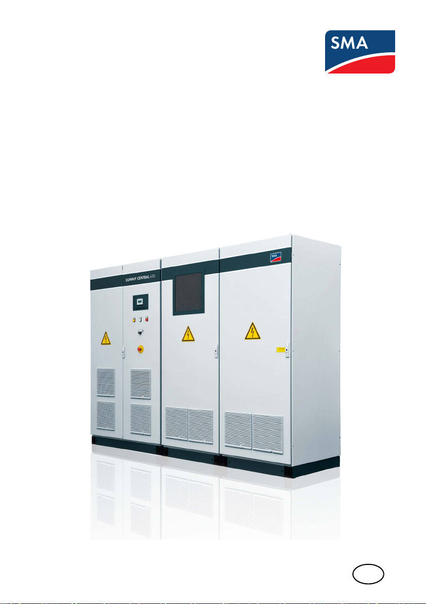
SUNNY CENTRAL 400HE / 500HE / 630HE
Installation Guide
SCxxxHE-IEN104432 | 98-4007732 | Version 3.2
Page 2

Page 3

SMA Solar Technology AG Table of Contents
Table of Contents
1 Notes on this Manual. . . . . . . . . . . . . . . . . . . . . . . . . . . . . . 7
1.1 Validity . . . . . . . . . . . . . . . . . . . . . . . . . . . . . . . . . . . . . . . . . . . . 7
1.2 Target Group . . . . . . . . . . . . . . . . . . . . . . . . . . . . . . . . . . . . . . . 7
1.3 Additional Information . . . . . . . . . . . . . . . . . . . . . . . . . . . . . . . . 7
1.4 Symbols Used . . . . . . . . . . . . . . . . . . . . . . . . . . . . . . . . . . . . . . . 8
2 Safety . . . . . . . . . . . . . . . . . . . . . . . . . . . . . . . . . . . . . . . . . . 9
2.1 Appropriate Usage. . . . . . . . . . . . . . . . . . . . . . . . . . . . . . . . . . . 9
2.2 Safety Precautions. . . . . . . . . . . . . . . . . . . . . . . . . . . . . . . . . . . 10
2.2.1 Personnel. . . . . . . . . . . . . . . . . . . . . . . . . . . . . . . . . . . . . . . . . . . . . . . . . . . . 10
2.2.2 Installation. . . . . . . . . . . . . . . . . . . . . . . . . . . . . . . . . . . . . . . . . . . . . . . . . . . 10
2.2.3 Special Hazards of Photovoltaic Plants. . . . . . . . . . . . . . . . . . . . . . . . . . . . . 11
2.2.4 Electrical Connection. . . . . . . . . . . . . . . . . . . . . . . . . . . . . . . . . . . . . . . . . . . 11
2.2.5 Power Supplies . . . . . . . . . . . . . . . . . . . . . . . . . . . . . . . . . . . . . . . . . . . . . . . 12
2.2.6 Disconnecting . . . . . . . . . . . . . . . . . . . . . . . . . . . . . . . . . . . . . . . . . . . . . . . . 13
2.2.7 General Information . . . . . . . . . . . . . . . . . . . . . . . . . . . . . . . . . . . . . . . . . . . 15
3 Delivery. . . . . . . . . . . . . . . . . . . . . . . . . . . . . . . . . . . . . . . . 16
3.1 Standard Scope of Delivery . . . . . . . . . . . . . . . . . . . . . . . . . . . 16
3.2 Scope of Delivery (depending on the model). . . . . . . . . . . . . . 18
3.3 Identifying your Sunny Central . . . . . . . . . . . . . . . . . . . . . . . . . 20
3.4 Check for Transport Damage . . . . . . . . . . . . . . . . . . . . . . . . . . 20
3.5 Storage . . . . . . . . . . . . . . . . . . . . . . . . . . . . . . . . . . . . . . . . . . . 21
4 Installation . . . . . . . . . . . . . . . . . . . . . . . . . . . . . . . . . . . . . 22
4.1 Installation Site Requirements . . . . . . . . . . . . . . . . . . . . . . . . . . 22
4.2 Electrical Operating Room . . . . . . . . . . . . . . . . . . . . . . . . . . . . 22
4.2.1 MV Stations. . . . . . . . . . . . . . . . . . . . . . . . . . . . . . . . . . . . . . . . . . . . . . . . . . 23
4.3 Ventilation . . . . . . . . . . . . . . . . . . . . . . . . . . . . . . . . . . . . . . . . . 27
4.3.1 Exhaust Airflow . . . . . . . . . . . . . . . . . . . . . . . . . . . . . . . . . . . . . . . . . . . . . . . 29
Installation Guide SCxxxHE-IEN104432 3
Page 4

Table of Contents SMA Solar Technology AG
4.4 Transport Options . . . . . . . . . . . . . . . . . . . . . . . . . . . . . . . . . . . 31
4.4.1 Transport Using a Pallet Truck or Forklift . . . . . . . . . . . . . . . . . . . . . . . . . . . . 32
4.4.2 Transport Using a Crane. . . . . . . . . . . . . . . . . . . . . . . . . . . . . . . . . . . . . . . . 33
4.5 On-Site Inverter Installation. . . . . . . . . . . . . . . . . . . . . . . . . . . . 34
4.5.1 Mechanical Coupling . . . . . . . . . . . . . . . . . . . . . . . . . . . . . . . . . . . . . . . . . . 34
4.5.2 Mechanical Coupling for the "Chemically Active" Option . . . . . . . . . . . . . . 35
4.5.3 Anchorage to the Ground or Wall . . . . . . . . . . . . . . . . . . . . . . . . . . . . . . . . 36
5 Internal Electrical Connections . . . . . . . . . . . . . . . . . . . . . 37
5.1 Connecting the Power Cable Connection. . . . . . . . . . . . . . . . . 37
5.1.1 Connecting the Power Cable for the "Chemically Active" Option. . . . . . . . . 41
5.2 Connecting the Internal PE Connection. . . . . . . . . . . . . . . . . . . 42
5.3 Connecting the Control Cables on the Transfer Terminal Strip . 44
5.3.1 Connecting the Control Cables to the Transfer Terminal Strip in the
AC Cabinet . . . . . . . . . . . . . . . . . . . . . . . . . . . . . . . . . . . . . . . . . . . . . . . . . . 45
5.4 Connecting the Sunny Central Control to the Power Unit. . . . . 46
5.5 Connecting the Internal Control Cables of the Power Unit . . . . 47
5.6 Connecting the Communication Unit for Insulation
Monitoring . . . . . . . . . . . . . . . . . . . . . . . . . . . . . . . . . . . . . . . . 48
6 External Connections . . . . . . . . . . . . . . . . . . . . . . . . . . . . . 49
6.1 Connecting High-Current Contacts . . . . . . . . . . . . . . . . . . . . . . 50
6.2 Connecting the AC Grid . . . . . . . . . . . . . . . . . . . . . . . . . . . . . . 53
6.2.1 Mounting and Dismounting the Plexiglas Cover and Sliding Plate . . . . . . . . 55
6.2.2 Procedure for Models 13/0 and 13/4 . . . . . . . . . . . . . . . . . . . . . . . . . . . . 58
6.2.3 Procedure for Model 13/1. . . . . . . . . . . . . . . . . . . . . . . . . . . . . . . . . . . . . . 59
6.2.4 Procedure for Model 13/2. . . . . . . . . . . . . . . . . . . . . . . . . . . . . . . . . . . . . . 61
6.2.5 Procedure for Model 13/3. . . . . . . . . . . . . . . . . . . . . . . . . . . . . . . . . . . . . . 62
6.2.6 Procedure for Model 13/5. . . . . . . . . . . . . . . . . . . . . . . . . . . . . . . . . . . . . . 65
6.2.7 Connecting the AC Cable. . . . . . . . . . . . . . . . . . . . . . . . . . . . . . . . . . . . . . . 67
6.3 AC Grid Connection for MV Stations . . . . . . . . . . . . . . . . . . . . 69
6.4 Connecting the PE Rail . . . . . . . . . . . . . . . . . . . . . . . . . . . . . . . 70
4 SCxxxHE-IEN104432 Installation Guide
Page 5

SMA Solar Technology AG Table of Contents
6.5 Connecting the Internal Power Supply . . . . . . . . . . . . . . . . . . . 72
6.5.1 Connecting the External Power Supply. . . . . . . . . . . . . . . . . . . . . . . . . . . . . 72
6.5.2 Connecting the Internal Power Supply . . . . . . . . . . . . . . . . . . . . . . . . . . . . . 74
6.6 Connecting the DC Cable. . . . . . . . . . . . . . . . . . . . . . . . . . . . . 76
6.6.1 Connecting the DC Cable to the Busbar. . . . . . . . . . . . . . . . . . . . . . . . . . . . 77
6.6.2 Connecting the DC Cable to the Low-Voltage HRC Fuses . . . . . . . . . . . . . . 78
6.6.3 Additional Connections of DC Main Distributors . . . . . . . . . . . . . . . . . . . . . 81
6.7 Analog Inputs . . . . . . . . . . . . . . . . . . . . . . . . . . . . . . . . . . . . . . 84
6.7.1 Analog Sensors. . . . . . . . . . . . . . . . . . . . . . . . . . . . . . . . . . . . . . . . . . . . . . . 84
6.7.2 External Signals. . . . . . . . . . . . . . . . . . . . . . . . . . . . . . . . . . . . . . . . . . . . . . . 84
6.7.3 Overview of the Analog Inputs . . . . . . . . . . . . . . . . . . . . . . . . . . . . . . . . . . . 85
6.7.4 Handling the Shield Contact . . . . . . . . . . . . . . . . . . . . . . . . . . . . . . . . . . . . . 85
6.8 Remote Deactivation Unit . . . . . . . . . . . . . . . . . . . . . . . . . . . . . 86
6.9 Serial Interfaces . . . . . . . . . . . . . . . . . . . . . . . . . . . . . . . . . . . . 87
6.10 Emergency Stop Cabling . . . . . . . . . . . . . . . . . . . . . . . . . . . . . 88
6.11 Overvoltage Protection . . . . . . . . . . . . . . . . . . . . . . . . . . . . . . . 88
7 Commissioning . . . . . . . . . . . . . . . . . . . . . . . . . . . . . . . . . . 89
7.1 Removing the Transport Locks. . . . . . . . . . . . . . . . . . . . . . . . . . 90
7.2 Checking the Sunny Central Cabling . . . . . . . . . . . . . . . . . . . . 91
7.2.1 Checking Internal Connections . . . . . . . . . . . . . . . . . . . . . . . . . . . . . . . . . . . 91
7.2.2 Checking the AC Grid Connection . . . . . . . . . . . . . . . . . . . . . . . . . . . . . . . . 91
7.2.3 Checking the Internal AC Power Supply. . . . . . . . . . . . . . . . . . . . . . . . . . . . 92
7.2.4 Checking the DC Cabling . . . . . . . . . . . . . . . . . . . . . . . . . . . . . . . . . . . . . . . 92
7.2.5 Checking the Connection of the Serial Interfaces . . . . . . . . . . . . . . . . . . . . . 92
7.2.6 Checking the Emergency Stop Cabling . . . . . . . . . . . . . . . . . . . . . . . . . . . . 92
7.2.7 Checking the Thermostat and Hygrostat Settings . . . . . . . . . . . . . . . . . . . . . 93
7.3 Checking the Voltages on the Sunny Central . . . . . . . . . . . . . . 93
7.4 Preparation for Commissioning. . . . . . . . . . . . . . . . . . . . . . . . . 95
7.5 Switching On . . . . . . . . . . . . . . . . . . . . . . . . . . . . . . . . . . . . . . 97
Installation Guide SCxxxHE-IEN104432 5
Page 6

Table of Contents SMA Solar Technology AG
8 Technical Data . . . . . . . . . . . . . . . . . . . . . . . . . . . . . . . . . . 98
8.1 Sunny Central 400HE-11 . . . . . . . . . . . . . . . . . . . . . . . . . . . . . 98
8.2 Sunny Central 500HE-11 . . . . . . . . . . . . . . . . . . . . . . . . . . . . 100
8.3 Sunny Central 630HE-11 . . . . . . . . . . . . . . . . . . . . . . . . . . . . 102
9 Contact . . . . . . . . . . . . . . . . . . . . . . . . . . . . . . . . . . . . . . . 104
6 SCxxxHE-IEN104432 Installation Guide
Page 7

SMA Solar Technology AG Notes on this Manual
1 Notes on this Manual
1.1 Validity
This manual describes the transport, installation, and commissioning of SMA central inverters of the
following types:
• Sunny Central 400HE (SC 400HE-11)
• Sunny Central 500HE (SC 500HE-11)
• Sunny Central 630HE (SC 630HE-11)
1.2 Target Group
This manual is intended for installers and operators of PV plants equipped with Sunny Centrals.
1.3 Additional Information
All manuals for the Sunny Central as well as for the installed components must be stored together with
the plant documentation and must be accessible at all times. The documents listed below are included
in the scope of delivery for your Sunny Central. The following information is contained in these
documents.
• Installation guide: Setup and installation of the Sunny Central
• User manual: How to operate the Sunny Central and Sunny Central Control
• Circuit diagrams: Variant circuit diagram of the Sunny Central
• Maintenance manual Regular maintenance work on the Sunny Central
• Maintenance protocol List of the regular maintenance work and its intervals as well as the
preventive replacement intervals of individual components.
• Commissioning report Check list for commissioning. After successful commissioning, the
commissioning report has to be sent to SMA Solar Technology AG.
• Accessory documentation: The documentation for optional accessories or optional equipment
for the Sunny Central can be found at www.SMA.de/en.
Installation Guide SCxxxHE-IEN104432 7
Page 8
Notes on this Manual SMA Solar Technology AG
1.4 Symbols Used
The following types of safety instructions and general information appear in this document as
described below:
DANGER
DANGER indicates a hazardous situation which, if not avoided, will result in death or
serious injury.
WARNING!
WARNING indicates a hazardous situation which, if not avoided, could result in death or
serious injury.
CAUTION!
CAUTION indicates a hazardous situation which, if not avoided, could result in minor or
moderate injury.
NOTICE!
NOTICE indicates a situation that can result in property damage if not avoided.
Information
Information provides tips that are valuable for the optimal installation and operation of
your product.
8 SCxxxHE-IEN104432 Installation Guide
Page 9
SMA Solar Technology AG Safety
2 Safety
2.1 Appropriate Usage
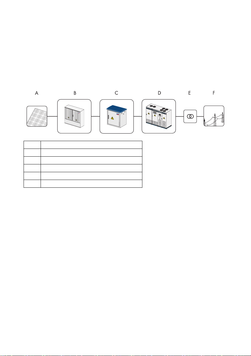
The Sunny Central is a PV inverter. It allows photovoltaic solar energy from solar modules to be
converted and fed into a medium-voltage grid.
Principle of a grid-tie PV plant with a Sunny Central
APV modules
B Sunny String-Monitor
C Sunny Main Box
D Sunny Central
E Medium-voltage transformer
F Electrical grid
Sunny Central HE
The Sunny Central HE is a high efficiency solar inverter. It does not have its own low-voltage
transformer. The Sunny Central HE requires an adapted external medium-voltage transformer via
which it can feed into the grid.
The following standards apply for all devices of this series:
EMC EN 61000-6-2, EN 61000-6-4
Grid monitoring As per BDEW regulations
CE conformity yes
Installation Guide SCxxxHE-IEN104432 9
Page 10
Safety SMA Solar Technology AG
2.2 Safety Precautions
Failures that affect or limit the safety of the device must be rectified immediately. Unauthorized
mo dif ica tio ns a nd t he u se o f sp are par ts n ot r eco mme nde d by SMA Solar Technology may cause fire,
material damage, and electrical shock. Unauthorized personnel must not have access to the devices.
Warning signs must always be clearly readable and immediately replaced if damaged.
2.2.1 Personnel
Any work on the Sunny Central may be executed by qualified technical personnel only. "Qualified"
means that the personnel must possess training relevant to the activity performed.
The personnel must be familiar with the content of the Sunny Central installation guide and user
manual in order to commission and / or operate the Sunny Central. Please observe all safety
information carefully.
2.2.2 Installation
The installation requirements described in the installation guide must be satisfied. Installation must
occur in an electrical operating room, in order to guarantee optimum noise and fire protection.
Wi th r ega rd t o the EMC lim it va lue s (E MC = ele ctr omag net ic c omp atibility), the Sunny Central device
range is type tested for installation in an industrial environment. Devices suitable for installation in
domestic areas are available on request.
The following points must be observed for the installation:
• The intake and exhaust ventilation systems for the Sunny Central must be separate to any other
ventilation systems so as to prevent smoke distribution in the event of a fire.
• A sufficient escape route must be guaranteed.
• Appropriate sound insulation must be provided.
• The EMC specifications must be observed (see technical data).
WARNING!
Smoke development in electrical operating rooms.
We recommend the installation of a smoke detector inside the operating room which
controls the external emergency stop switch of the device and switches off the Sunny
Central in the event of smoke.
10 SCxxxHE-IEN104432 Installation Guide
Page 11

SMA Solar Technology AG Safety
2.2.3 Special Hazards of Photovoltaic Plants
Photovoltaic plants have special characteristics representing special hazards that are described here:
• An active power source is connected. Depending on the operating mode, there may be voltage
present from the photovoltaic generator and/or the Sunny Central. This is especially important
to note when disconnecting particular parts of the plant.
• V ery hig h DC vol tag es ar e pr ese nt ( no z ero -cro ssi ng) tha t, i n the case of a fault or inappropriate
use of fuses or plugs, may lead to arcing.
• The short circuit current of the photovoltaic generator is only slightly higher than the maximum
operating current and also depends on the irradiation. If a short-circuit occurs in the plant, the
available fuses are not guaranteed to switch off.
• The grid structure of the PV generator is generally a non-grounded grid that could become
unintentionally grounded if a ground fault occurs.
• A highly branched generator array may be difficult to disconnect if a fault develops (e.g. short
circuit). We recommend the extra use of external DC circuit breakers for disconnecting the
inverter and / or the DC main cables / Sunny String-Monitors, DC circuit breakers optionally
available. At every DC input, an easily accessible DC circuit breaker should be installed. For
further information see pre-standard VDE 0100, part 712 and VDI guideline 6012.
2.2.4 Electrical Connection
The electrical connection must be performed according to this installation guide, the variant circuit
diagram and the technical data of the device.
Ensure the grid connection cable for grid feeding-in is fused at the nominal current indicated on the
type plate. If the specified nominal current differs from the nominal current of the fuse plug, the fuse
plug having the next highest nominal current may be used.
Grid connection cable
The grid connection cable for the in ter nal pow er s upp ly m ust be secured with the line circuit
breaker specified in the technical data.
Lightning Protection
The devices have type I internal lightning protection on the AC side and type II internal overvoltage
protection on the DC side and the internal power supply. However, the desired protection level can
only be achieved if a lightning protection area concept exists for the installation building as per
DIN VDE 0185-4, i.e. lightning conductors or combined overvoltage and lightning conductors
(n ot i ncl ude d in deli ver y) a re a vailabl e at loc ati ons includi ng t he b uil ding’s e ntr anc e (t ransfer l igh tning
protection area LPZ 1).
Combined overvoltage and lightning protection for the signal inputs can be optionally ordered.
Installation Guide SCxxxHE-IEN104432 11
Page 12
Safety SMA Solar Technology AG
Emergency Stop
In plants having more than one device, the respective emergency stop switches must be connected
to get her and checked f or c orr ect operati on a s de scr ibe d in thi s in sta lla tio n gu ide. The eme rge ncy sto p
circuit may only be supplied with voltage from a single device.
Emergency stop circuit
• The emergency stop circuit may only be supplied by a Sunny Central.
• Correctly mount the bridges on the device's emergency stop terminal strip.
2.2.5 Power Supplies
WARNING!
Risk of lethal electric shock.
High voltages are present in the device.
• The grounding conductor must be made before the external voltage is switched on.
• At the AC grid connection terminal, the nominal voltage, frequency and the
right‑hand rotary field have to be maintained.
• The correct polarity and ungroundedness must be ensured before inserting the DC
input fuses (internal or external). The fuses may only be inserted and / or removed
under load-free conditions and using the appropriate personal protective equipment
and fuse carriers.
• When the DC fuses (internal or external) have been inserted, reverse voltage exists,
via the Sunny Central busbars, on all externally connected DC main distribution
boxes and DC sub-distribution boxes (Sunny String Box).
• The doors must remain closed when connecting the supplies!
Requirements for the Use of External Power Supplies
• All connections have been made according to the installation guide and the circuit diagram.
• The grounding conductor for grid feed-in and for internal power supply has been made.
• The device is switched off. The key switch is in the “Stop” position and the main switches are off.
• The DC input fuses (internal or external) are connected and the protection against contact
(Plexiglas covers) is mounted.
• The nominal voltages, frequencies and the right-hand rotary field are maintained.
• The polarity of the DC voltage at the inputs / fuse inputs (device dependent) has been checked.
• The polarity of the DC voltages at the inverter input (device dependent) has been checked.
• The photovoltaic generator has been checked with an insulation test to ensure that there is no
ground fault.
12 SCxxxHE-IEN104432 Installation Guide
Page 13
SMA Solar Technology AG Safety
Sequence for Switching On the External Power Supplies
1. Grid voltage for grid feeding
2. Grid voltage for internal power supply
3. DC voltage from the photovoltaic generator
2.2.6 Disconnecting
External isolation of the device must always occur under load-free conditions. The device must be
switched off in order to do this, i.e. the key switch must be in the “Stop” position.
DANGER!
Risk of lethal electric shock.
Work on the Sunny Central may be performed only after switching off the power to the
unit. The VDE regulations must be followed:
•Disconnect
• Ensure that the device cannot be reconnected
• Ensure that no voltage is present
• Ground and short-circuit the unit if necessary (not on the DC side)
• If necessary, cover or shield any adjacent live components
The following power supplies must be isolated:
• Grid voltage for grid feeding
• Grid voltage for internal power supply (optional)
• DC voltage from the photovoltaic generator
• Additional external voltage if necessary (e.g. emergency stop)
Simply switching off the main AC and DC switches is not sufficient to ensure proper isolation of the
device. The main switches only separate the power circuit from the grid and the photovoltaic
generator.
DANGER!
Risk of lethal electric shock.
Dangerous accidental-contact voltages can be present in the Sunny Central even when the
main AC and DC switches are switched off!
• Wait at least 5 minutes after switching off the Sunny Central.
The DC voltage is isolated using the internal or external DC input fuses, or using an external circuit
breaker if present. Isolation by removing the DC input fuses must occur under load-free conditions.
Installation Guide SCxxxHE-IEN104432 13
Page 14
Safety SMA Solar Technology AG
Th e de vic e con tai ns c apa cit ors on th e AC and DC si des tha t mus t di scha rge onc e the dev ice has bee n
switched off. After switching off, dangerous accidental-contact voltages remain within the device for
several minutes. If there is a fault in the device, these voltages may also be present for a longer period
of time. Wait at least 5 minutes after switching off the device before opening the device.
WARNING!
Risk of lethal electric shock!
• To avoid arcing, the load-free status of the device must be checked with a current
probe (using a clamp-on ammeter) before removing the DC input fuses. The fuses
may only be inserted or removed using the appropriate personal protective
equipment and fuse carrier.
• When the DC fuses (internal or external) have been inserted, reverse voltage exists,
via the Sunny Central busbars, on all externally connected DC main distribution
boxes and DC sub-distribution boxes (Sunny String-Monitor).
• In the event of a failure, the DC contactor may carry a life-threatening DC voltage!
• The discharge time of the capacitors is longer than 5 minutes.
To extract the fuses, the Plexiglass cover must be removed. Immediately reinstall the cover after the
cover has been removed from one pole and the fuse has been extracted. The cover must always be
mounted unless a fuse is to be extracted.
Disconnecting plant parts without danger
We recommend the extra use of external DC circuit breakers for disconnecting the
Sunny Central, DC main cables and Sunny String-Monitor; DC circuit breakers are
optionally available. This allows system components to be safely isolated, even in the case
of faults or fire.
14 SCxxxHE-IEN104432 Installation Guide
Page 15

SMA Solar Technology AG Safety
2.2.7 General Information
Ear Protection
The device fans and the power module create significant levels of operating noise. In addition to this,
a fault in the device can lead to very high sound levels.
High noise levels in electrical operating rooms
We recommend the use of ear protection when in the vicinity of the Sunny Central
operating room for extended periods.
Burns
Immediately after isolating the device, depending on the operating conditions, certain components
can be very hot (e.g. fuses, transformer core, sinusoidal filter, heat sinks etc.).
Safety gloves should always be worn when working near components that can be expected to be
very hot.
High temperature on device parts
We recommend that safety gloves be worn during all work on the device.
Installation Guide SCxxxHE-IEN104432 15
Page 16

Delivery SMA Solar Technology AG
3 Delivery
3.1 Standard Scope of Delivery
Position Quantity Designation
A 1 DC / inverter cabinet
B 1 AC cabinet
C1Power cabling
D 1 SMA document set
• Installation guide
• User manual
• Variant circuit diagram
• Commissioning report
E 1 Documentation of the optional insulation monitoring (Bender)
F 1 Low-voltage HRC fuse carrier, optional
G 2 Terminal profile, 3 m Rittal SZ 2573.000
16 SCxxxHE-IEN104432 Installation Guide
Page 17
SMA Solar Technology AG Delivery
Position Quantity Designation
H 1 Rittal assembly set
• Delivery pouch, 2-door TS8 1200 x 2000
• Angle bracket TS corner TS8800.430
• Quick angle connector TS TS8800.500
• Rittal angle plate PS 4582.500
• Sealing tape
I1 4 Shield clamping saddle 7 - 16mm Wago 790-116
I2 5 Shield clamping saddle 0 - 8mm Wago 790-108
K1 6 OBO cable clip 34 – 40 mm
K2 17 OBO cable clip 28 – 34 mm
K3 21 OBO cable clip 22 – 28 mm
K4 14 OBO cable clip 12 – 16 mm
L1 6 OBO opposite sleeve 1197169 2058 FW/40
L2 17 OBO opposite sleeve 1197282 2058 FW/34
L3 21 OBO opposite sleeve 1197347 2058 FW/28
L4 14 OBO opposite sleeve 1197401 2058 FW/16
Installation Guide SCxxxHE-IEN104432 17
Page 18
Delivery SMA Solar Technology AG
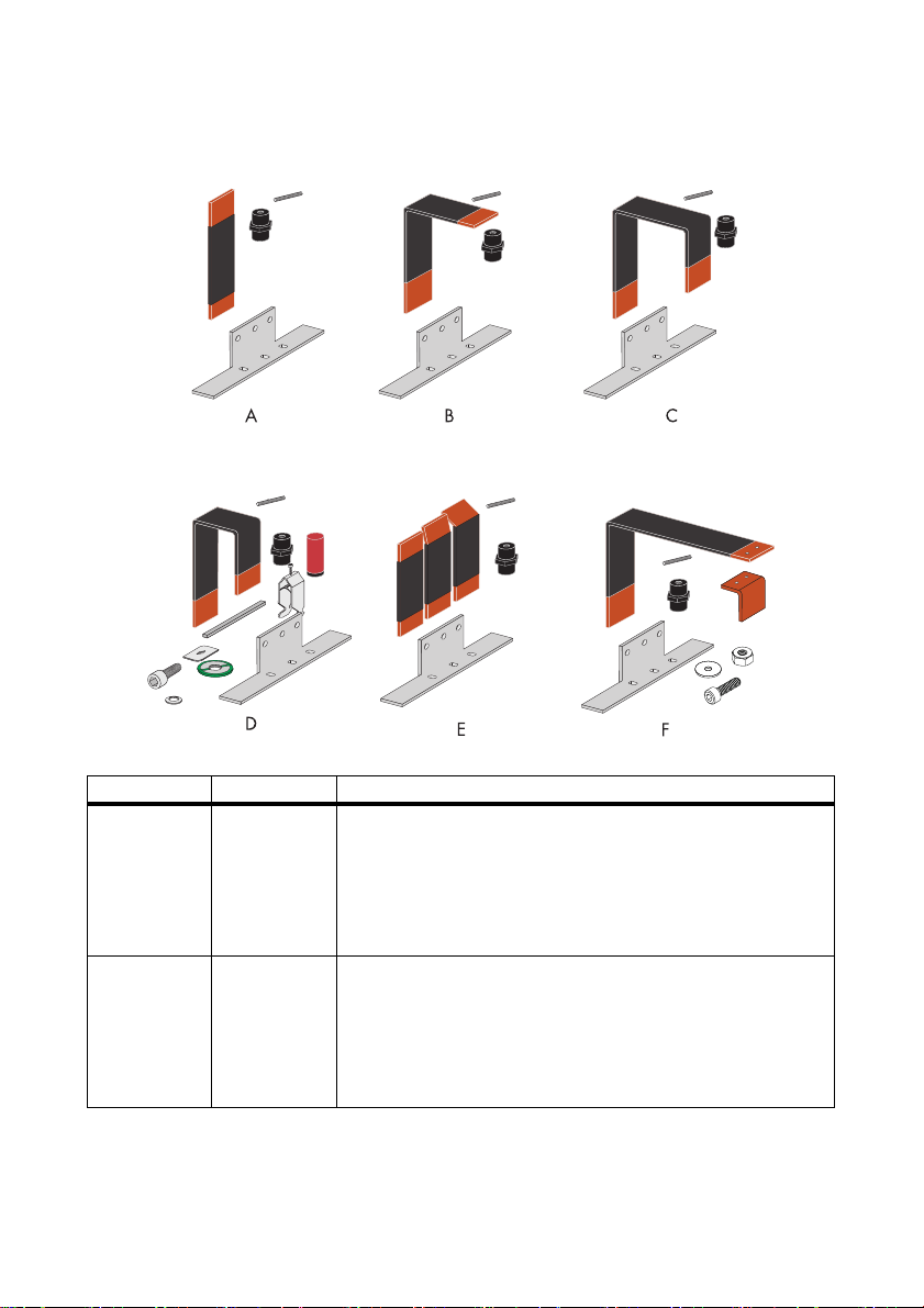
3.2 Scope of Delivery (depending on the model)
Position Quantity Designation
A 1 AC connection model 13/0:
• 3 x straight copper bar (same length)
• 3 x insulator
• 1 x retaining bracket
• 3 x insulator and setscrew
B 1 AC connection model 13/1:
• 3 x L-shaped copper bar
• 3 x insulator
• 1 x retaining bracket
• 3 x insulator and setscrew
18 SCxxxHE-IEN104432 Installation Guide
Page 19
SMA Solar Technology AG Delivery
Position Quantity Designation
C 1 AC connection model 13/2:
• 3 x U-formed copper bar
• 3 x insulator
• 3 x insulator and setscrew
D 1 AC connection model 13/3:
• 3 x U-formed copper bar
• 3 x support
• 1 x retaining bracket
• 3 x insulator and setscrew
• 18 x cable clip and opposite sleeve
• 3 x cable rail for side panels
• 6 x sliding nut
E 1 AC connection model 13/4:
• 3 x copper bar, varying angles
• 3 x insulator
• 1 x retaining bracket
• 3 x insulator and setscrew
F 1 AC connection model 13/5
• 3 x copper bar 2 x angled + separated
• 3 x insulator
• 1 x retaining bracket
• 3 x insulator and setscrew
• 6 x screw connector for the separated bars
Retaining brackets on the device
The retaining brackets are pre-installed on the device.
Installation Guide SCxxxHE-IEN104432 19
Page 20
Delivery SMA Solar Technology AG
A
SUNNY CENTRAL 630HE
AA
SMA
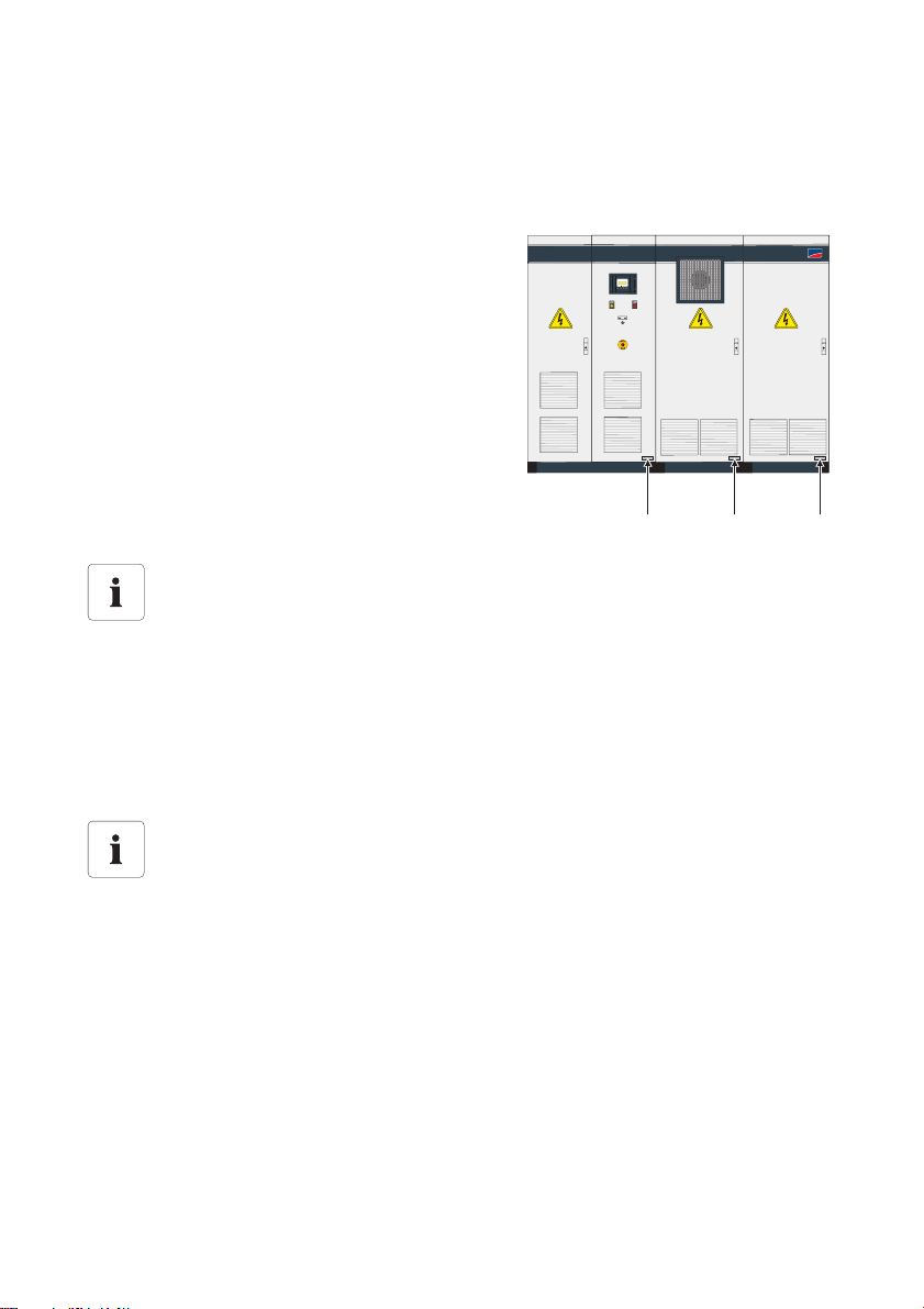
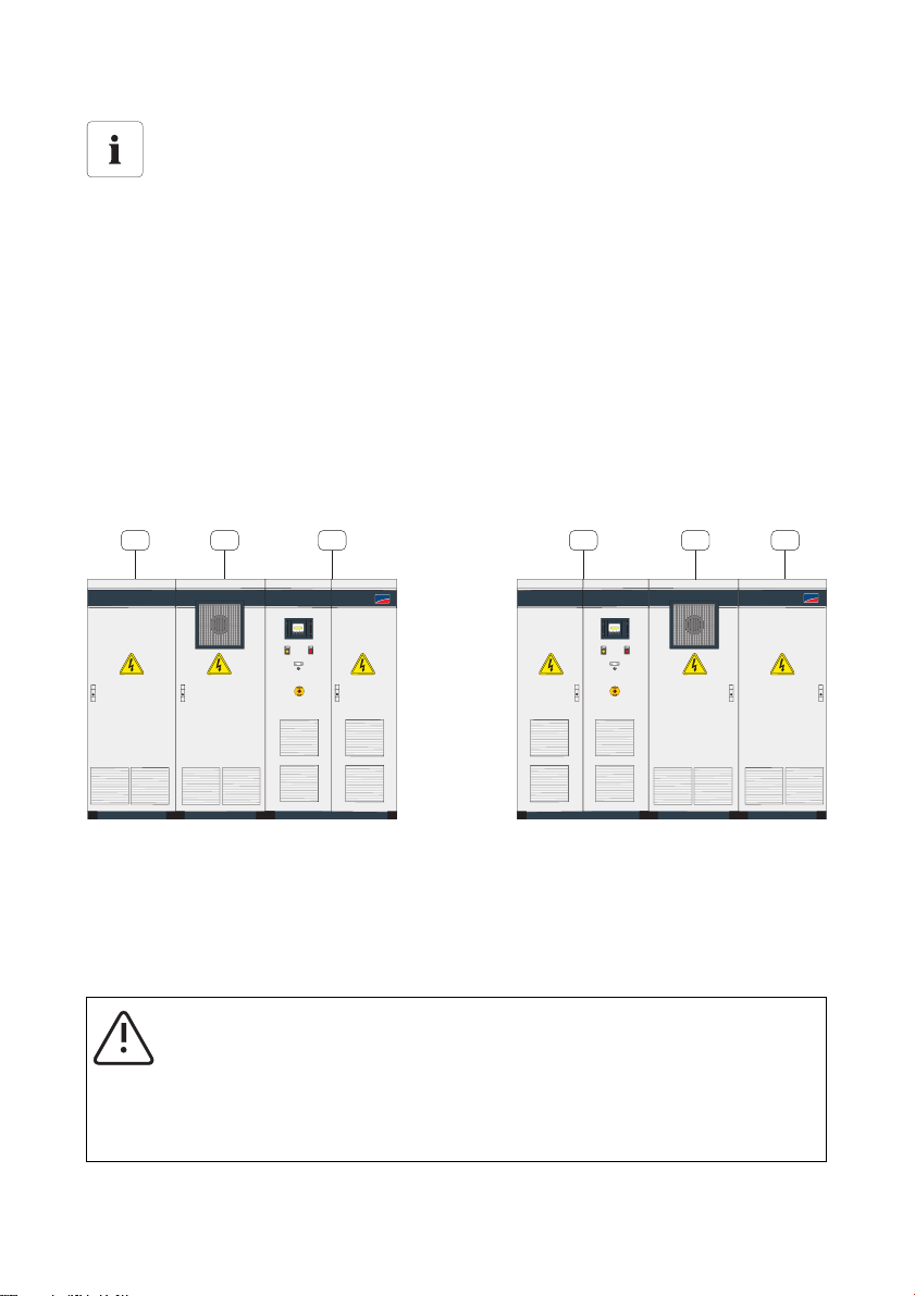
3.3 Identifying your Sunny Central
You can identify the Sunny Central using the type label. The type label is located on the inside of the
Sunny Central’s door.
In addition, the series number (A) is located on the front
side of the device.
Selecting switch cabinet units
Sunny Centrals are supplied as two switch cabinet units. If several Sunny Centrals are
delivered and installed together, switch cabinet units with the same serial number have to
be installed side by side.
3.4 Check for Transport Damage
Check the packaging and the device for any possible damage and compare the scope of delivery
with the delivery documentation. In the case of damage to the device and/or unclear delivery
contents, immediately contact SMA Solar Technology.
Transport safety
The inverters are delivered as two separate switch cabinet units. They do not satisfy the
protection class requirements as specified in the technical data. The transport packaging
provides sufficient protection against moisture and damage.
20 SCxxxHE-IEN104432 Installation Guide
Page 21
SMA Solar Technology AG Delivery
3.5 Storage
The switch cabinet units do not satisfy the protection class requirements as specified in the technical
data. The transport packaging provides sufficient protection against moisture and damage after
shipping. The switch cabinet units may not be stored outdoors.
Notice!
Improper storage may cause damage to the Sunny Central.
Improper storage can cause moisture or dust to seep into the Sunny Central.
• Only store the Sunny Central in areas where it is protected from dust and moisture.
• The conditions under which the Sunny Central is stored must correspond to the
intended operating conditions.
• Do not store the Sunny Central outdoors.
Installation Guide SCxxxHE-IEN104432 21
Page 22

Installation SMA Solar Technology AG
4 Installation
Sunny central installation requirements
Each Sunny Central has individual installation requirements. These can be ordered at any
time from SMA Solar Technology and have to be observed for project planning and
preparation of the installation site.
Selecting switch cabinet units
During installation and internal cabling, make sure the switch cabinet units have the same
series number.
4.1 Installation Site Requirements
Sunny central installation location
The Sunny Central should be installed in an electrical operating room.
Floor
The foundation must guarantee solid and safe positioning of the inverter. The foundation must provide
the load-carrying capacity necessary to cope with the weight of the inverter. The inverter cabinet must
be installed on a level surface. Any existing unevenness, depression or slope must be corrected prior
to installation.
Wall Clearances
When installing the inverter, appropriate distance to the wall for minimum passageways, escape
routes, and ventilation have to be observed. Appropriate specifications for each type of inverter are
contained in the Sunny Central Installation Requirements (separate document).
Inverter Protection Rating / EMC / Sound Levels
The Sunny Central is suitable for a dry, dust-reduced environment, according to IP20 protection rating.
With regard to the EMC emissions and the noise level, the Sunny Central inverter is conceived for
setup in an industrial environment.
4.2 Electrical Operating Room
For the installation and connection of the Sunny Central central inverters, observe DIN VDE 0100,
part 729, part 731. The requirements for the electrical operating room for the installation of highvoltage systems up to 1 000 V as well as the requirements for passageways and escape routes are
included therein.
22 SCxxxHE-IEN104432 Installation Guide
Page 23
SMA Solar Technology AG Installation
A
B
C C
B
A
SUNNY CENTRAL 630HESUNNY CENTRAL 630HE
SMA
SMA
Minimum passageway in electrical operating rooms
Observe the following points for a minimum passageway:
• With fully opened switch cabinet doors, a minimum passage width of 500 mm
(escape routes) must be maintained, see DIN VDE 0100 part 729, part 731.
• To maintain the minimum passageway requirements, the cabinet doors in an inverter
system with two rows of opposing cabinets (e.g. in a station building) may only be
opened on one side at a time.
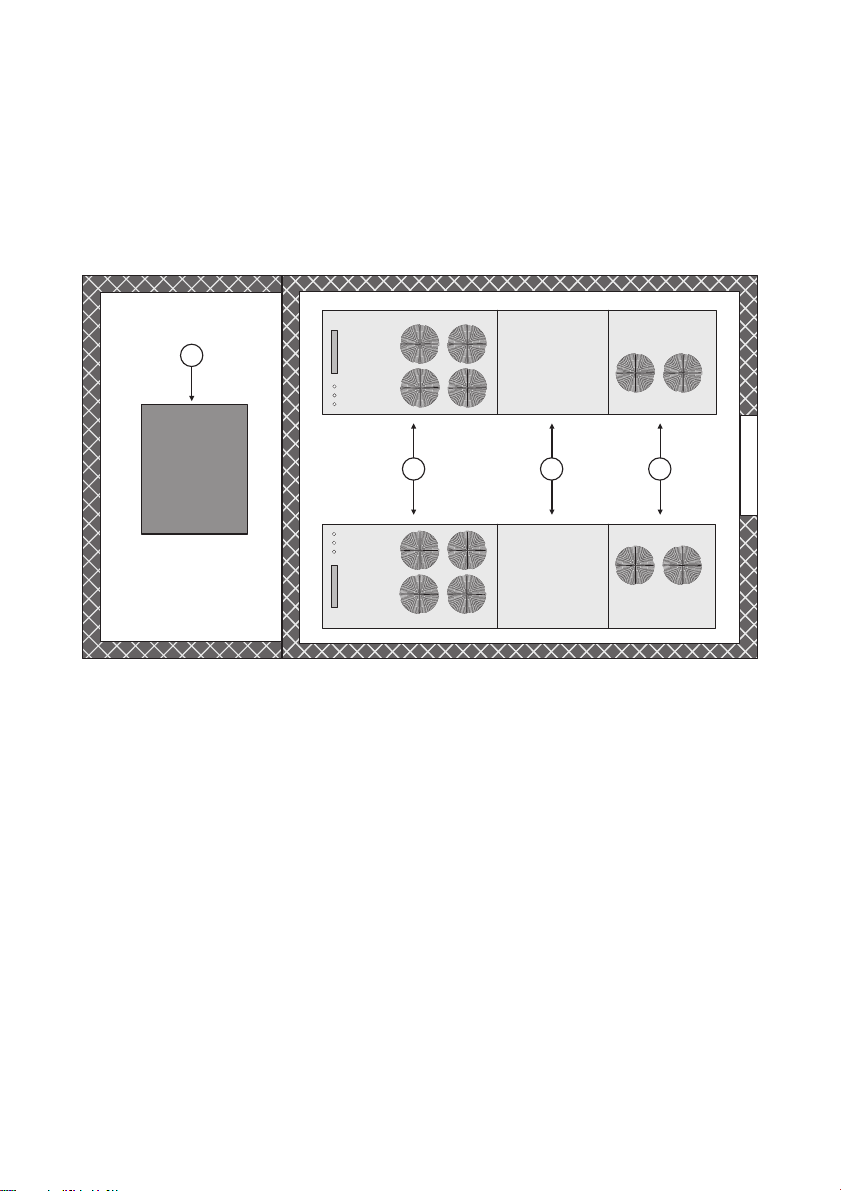
4.2.1 MV Stations
Inverters in the HE se ries ar e normally s et up in a compa ct concrete substation, opposite to each other
as a “left-hand system” and a “right-hand system”. The installation h as t o be car rie d ou t in accorda nce
with the VDE guidelines for a closed electrical operating room. The figure below depicts a left-hand
and a right-hand system.
Left system Right system
ADC cabinet
BInverter cabinet
CAC cabinet
The AC cabinets should always stand next to the dividing wall to the transformer room, to allow the
AC power cables to be connected to the transformer over the shortest possible route.
WARNING!
Smoke development in electrical operating rooms.
We recommend the installation of a smoke detector inside the operating room which
controls the external emergency stop connection of the device and which switches off the
Sunny Central in the event of smoke.
Installation Guide SCxxxHE-IEN104432 23
Page 24
Installation SMA Solar Technology AG
A B C
D
Sunny Centrals in a Station
A selection of schematic top views of a Sunny Central installed in a station and a transformer room
are included below. The inverter has bee n installed as a “ right -hand system” (above) and a “left-hand
system” (below). A station may also include only one Sunny Central. In addition to a transformer, the
option exists to also include a medium-voltage switchgear in a transformer room.
MV Station with two Sunny Centrals without Medium-Voltage Switchgear
A AC cabinet
B Inverter cabinet
C DC cabinet
DTransformer
24 SCxxxHE-IEN104432 Installation Guide
Page 25
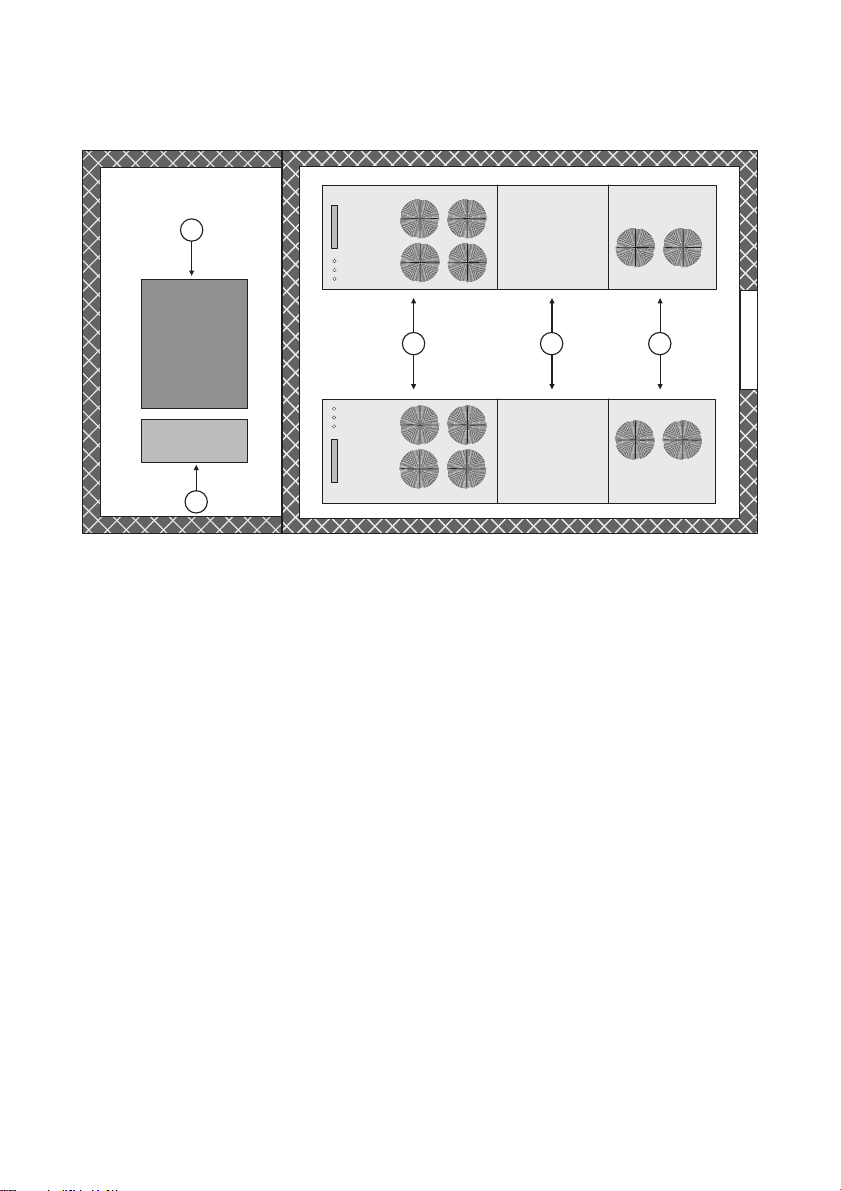
SMA Solar Technology AG Installation
A B C
D
E
MV Station with two Sunny Centrals and Medium-Voltage Switchgear
A AC cabinet
B Inverter cabinet
C DC cabinet
DTransformer
E Medium-voltage switchgear
Installation Guide SCxxxHE-IEN104432 25
Page 26
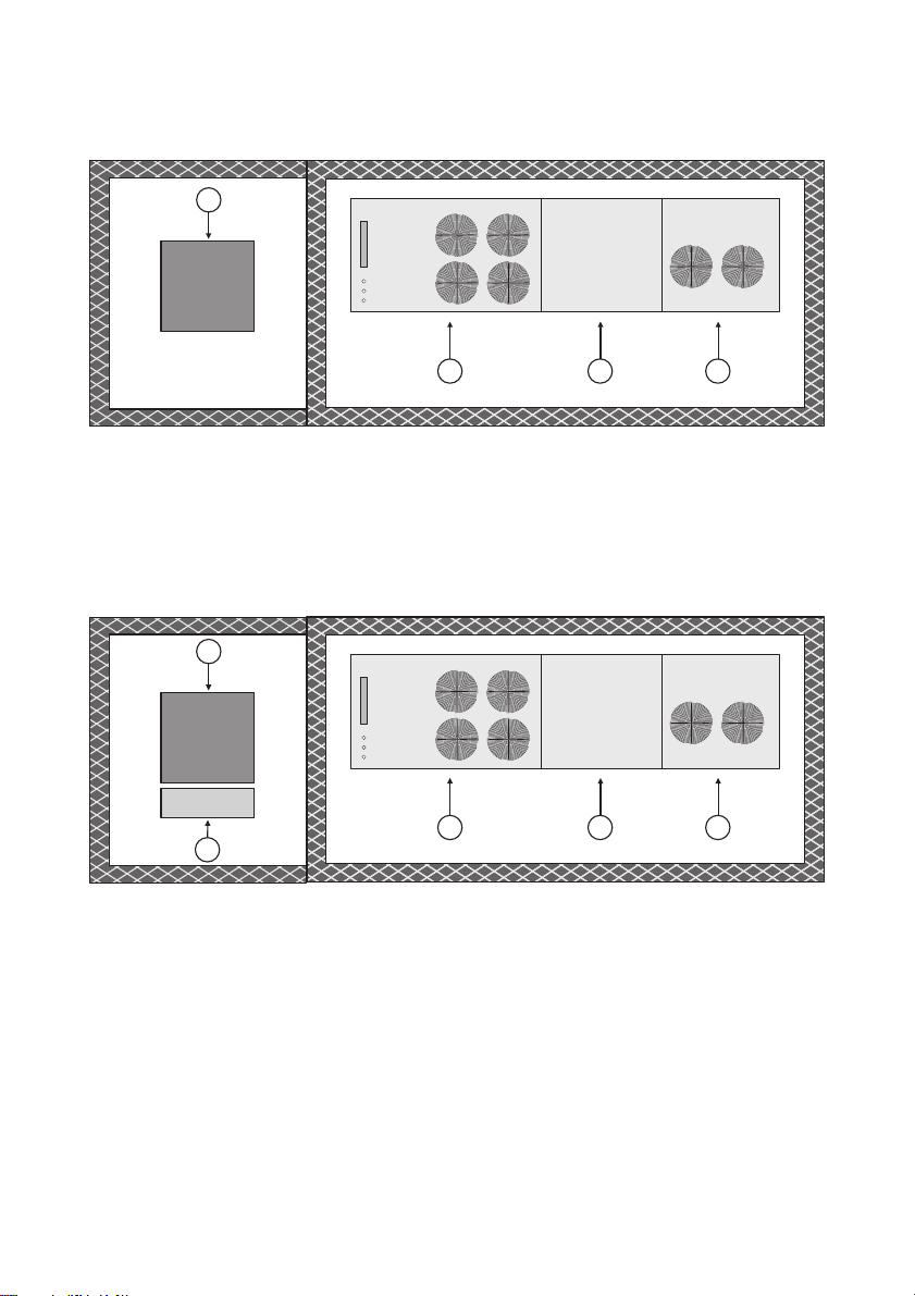
Installation SMA Solar Technology AG
A B C
D
A B C
D
E
MV Station with one Sunny Central without Medium-Voltage Switchgear
A AC cabinet
B Inverter cabinet
C DC cabinet
DTransformer
MV Station with one Sunny Central and Medium-Voltage Switchgear
A AC cabinet
B Inverter cabinet
C DC cabinet
DTransformer
E Medium-voltage switchgear
26 SCxxxHE-IEN104432 Installation Guide
Page 27
SMA Solar Technology AG Installation
4.3 Ventilation
Appropriate inlet ventilation is required for cooling the inverter. In order to guarantee safe operation
and maximum feed-in power, the permissible ambient temperature must be observed.
The required air is drawn through the switch cabinet doors and is blown out via the roof or the rear
pa nel of t he c abi net uni t de pen din g on the Sun ny C ent ral model Thi s al low s th e de vic es t o be ins tal led
directly next to each other. See the Sunny Central Installation Requirements (separate document) for
the air requirements as well as appropriate wall clearances. Filters for cleaning the inlet air are
installed at the inlet vents.
If the required volume of air at the installation site of the Sunny Central is too small, then on-site
measures must be taken to provide greater quantities of air (ventilation grills, blowers, fans, etc.).
The inlet air must satisfy the requirements of classification 3S2 (see table). Classification 3C2 must be
met if installation is to occur in chemically aggressive environments, e.g. installation near the sea. The
operation of the inverter is suited to a relative humidity of 15 … 95 %.
Air Quality Classification for Mechanically Active Substances
Environmental conditions for stationary
application
3S1 3S2 3S3 3S4
Class
a) Sand in the air [mg / m³] - 30 300 3 000
b) Dust (suspended matter) [mg / m³] 0.01 0.2 0.4 4.0
c) Dust (fallout) [mg / m³] 0.4 1.5 15 40
Sites where appropriate measures are taken to
xxxx
keep dust levels to a minimum.
Sites where no special measures have been taken
xxx
to reduce the sand or dust levels and which are
not located in the vicinity of sand or dust sources.
Sites near sand and dust sources x x
Sites in production halls where sand or dust is
x
present, or sites in geographical locations where
the air is prone to high levels of sand and dust.
Installation Guide SCxxxHE-IEN104432 27
Page 28
Installation SMA Solar Technology AG
Air Quality Classification for Chemically Active Substances
Environmental conditions for stationary
application
Class
3C1R 3C1L 3C1 3C2 3C3 3C4
a) Marine salt - - - Occurrence of marine
salt
b) Sulfur dioxide, mg / m³ 0.01 0.1 0.1 1.0 10 40
c) Hydrogen sulfide, mg / m³ 0.0015 0.01 0.01 0.5 10 70
c) Chlorine, mg / m³ 0.001 0.01 0.1 0.3 1.0 3.0
d) Hydrogen chloride, mg / m³ 0.001 0.01 0.1 0.5 5.0 5.0
e) Hydrogen fluoride, mg / m³ 0.001 0.003 0.003 0.03 2.0 2.0
f) Ammonia, mg / m³ 0.03 0.3 0.3 3.0 35 175
g) Ozone, mg / m³ 0.004 0.01 0.01 0.1 0.3 2.0
h) Nitrogen oxides, mg / m³ 0.01 0.1 0.1 1.0 9.0 20
Installation sites with carefully monitored and
x xxxxx
regulated atmospheres (category clean
spaces).
Installation sites with carefully regulated
xxxxx
atmospheres.
Installation sites in rural or densely populated
xxxx
areas with little industry and moderate traffic
volume.
Installation sites in densely populated areas
xxx
with industry and high traffic volume.
Installation sites directly neighboring industrial
xx
plants, with chemical emissions.
Installation sites directly inside of industrial
x
plants, with emission of high concentrations of
chemical pollutants.
Environmental Conditions
The following points must be observed in relation to environmental conditions:
• Required amount of fresh air
• Stipulated air quality
• Relative humidity
• Permissible ambient temperature
28 SCxxxHE-IEN104432 Installation Guide
Page 29
SMA Solar Technology AG Installation
4.3.1 Exhaust Airflow
The heated exhaust air generated by the inverter must be ducted away from the device so that the
maximum permissible environmental temperature is not exceeded and / or the war m ex hau st ai r do es
not unnecessarily heat the installation room.
CAUTION!
Risk of crushing from metal parts.
• Remove the finger protection from the fan openings of the Sunny Central before
installing the exhaust airflow.
The exhaust airflow of the DC and AC cabinets occurs upward. This is achieved through the on-site
installation of an exhaust airflow (e.g. air conduit).
The exhaust airflow of the inverter cabinet occurs on the rear-side. The Sunny Central can be set up
with the rear panel directly against the opening in the building wall. An on-site sealing or a frame-like
air box with seals is to be installed for this purpose. The air box must be fastened onto the building
wall.
NOTICE!
Operational reduction of the Sunny Central through overtemperature!
For an appropriate cooling of the inverter, the following points have to be observed:
• Observe the indicated amount of air.
• Clean the ventilation openings (filter pads) and the exhaust grills at regular intervals.
• Expel the exhaust air separately out of the individual cabinet components in order to
avoid thermal short circuit breaks.
Information regarding the inverter
The specific configuration of the ventilation systems for each inverter is to be taken from the
Sunny Central Installation Requirements (separate document).
Installation Guide SCxxxHE-IEN104432 29
Page 30
Installation SMA Solar Technology AG
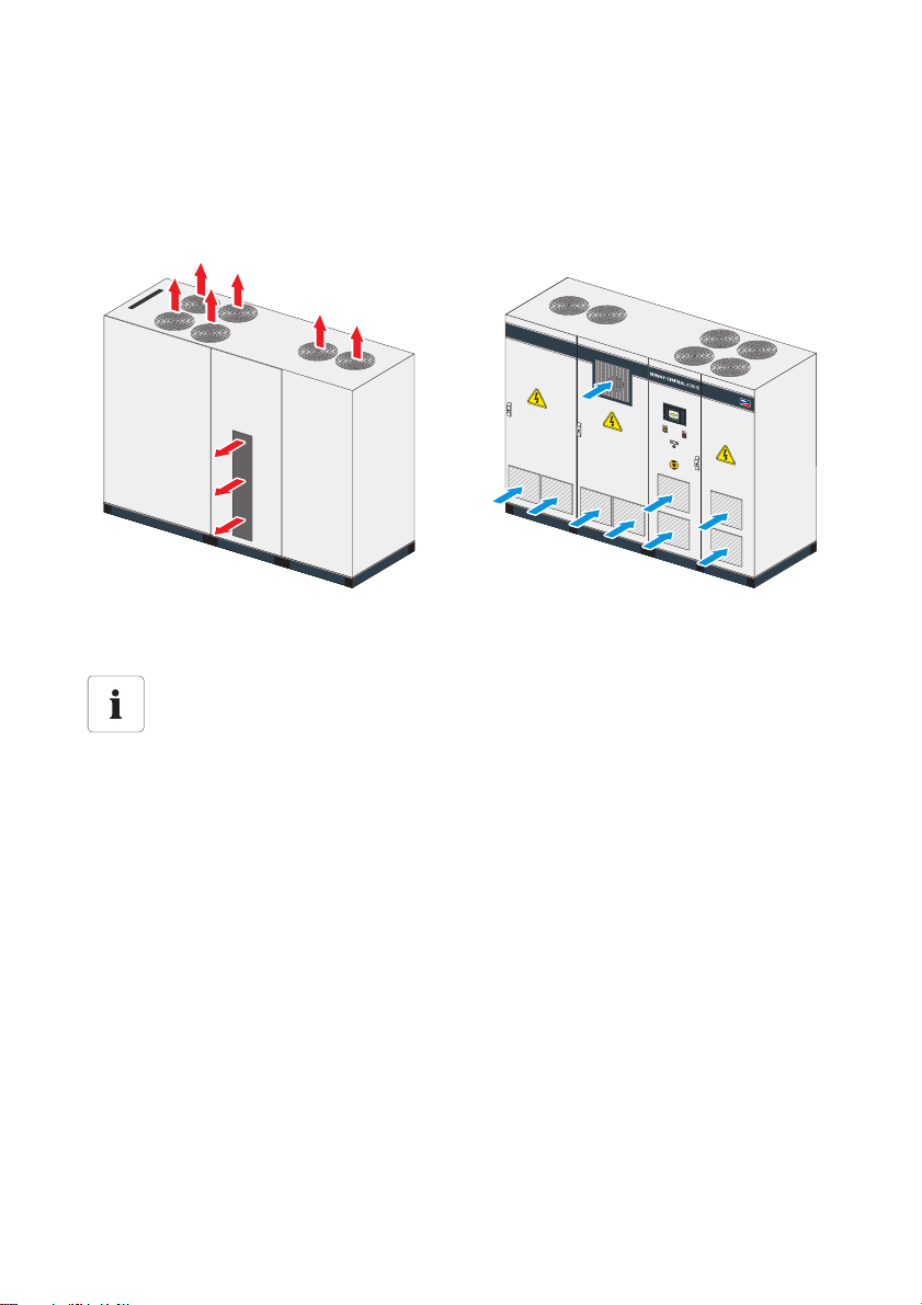
Overview of the Air Inlets and Outlets
Examples are used below to illustrate the exact position and size of the single air grills as well as for
the supply air on the front side (B) and the exhaust air on the roof or at the rear side (A) of the switch
cabinets.
AExhaust air BSupply air
Exact dimensions
For exact dimensions, please refer to the Installation Requirements of the relevant device.
The Installation Requirements are available at www.SMA.de/en.
30 SCxxxHE-IEN104432 Installation Guide
Page 31

SMA Solar Technology AG Installation
4.4 Transport Options
The inverter consists of two switch cabinet units, the DC / inverter cabinet and the AC cabinet, which
are separately transported and assembled together on site.
The inverters and switch cabinet units are delivered on pallets. A fork lift or a hoist is used to transport
the device to its final mounting location.
WARNING!
Heavy weight of the switch cabinet units!
Danger of tipping during transport!
• The cabinet units must always be transported in an upright position.
• When unloading, the heavy-load
markings must be given due
consideration.
– The center of gravity of the
Sunny Central is marked on the
outside of the packaging and on the
switch cabinet units.
– The labeling on the switch cabinet
units can be removed residue-free
following installation.
NOTICE!
Missing base panels could damage the Sunny Central.
• The base panels are essential for stable positioning of the switch cabinet.
• In the case of transport on a pallet, it is necessary to install the base panels.
Otherwise there is the danger that the base will collapse under the weight of the
switch cabinet.
Remove side base panels for cable routing
In the final installation location, one of the side base panels can be removed for cable
routing. The stability of the switch cabinet is still guaranteed.
Installation Guide SCxxxHE-IEN104432 31
Page 32

Installation SMA Solar Technology AG
SMA
SUNN
Y CENTRAL 630HE
S
U
N
N
Y
C
EN
TR
A
L 6
3
0
H
E
4.4.1 Transport Using a Pallet Truck or Forklift
1. Unscrew the base panels on the front and back base.
2. The two screws per base panel can be unscrewed
using a Torx TX30 screwdriver.
3. Insert the fork of a pallet truck or forklift under the
cabinet.
32 SCxxxHE-IEN104432 Installation Guide
Page 33

SMA Solar Technology AG Installation
4.4.2 Transport Using a Crane
NOTICE!
Inappropriate transport could cause damage to the Sunny Central.
In case of transport using a crane, the following points have to be observed:
• Asymmetric weight distribution
•Heavy duty
• The weight of the switch cabinet units is mainly distributed to the rear of the cabinet.
1. Unscrew the base panels on the front and back; see 4.4.1”Transport Using a Pallet Truck or
Forklift” (page32).
2. Insert the fork of a crane under the cabinet.
Transport using crane eyelets.
The heavy weight of the individual switch cabinet units means that transport using crane
eyelets is not permitted. A suitable crane fork should be used instead.
Installation Guide SCxxxHE-IEN104432 33
Page 34

Installation SMA Solar Technology AG
4.5 On-Site Inverter Installation
After both switch cabinet units have been installed next to each other, the transport locks of the
sinusoidal filter have to be removed, the seals have to be inserted and the individual cabinets have to
be mec han ica lly and elec tri cal ly c onn ect ed for th e fi nal mou nti ng in the operating room. All necessary
materials required for connecting the switch cabinets are included in the delivery.
4.5.1 Mechanical Coupling
NOTICE!
Moisture ingress due to lack of sealing!
• Before the two cabinets can be mechanically joined together, the seals provided must
be glued into the appropriate recesses in the cabinets, if this has not already been
done by default.
The mechanical connection of the two cabinets is done using baying clamps. They consist of terminal
clamps and brackets with which the cabinets can be screwed together in several places. In order to
do this, both cabinets have to be at the same level.
NOTICE!
Damage due to impurities!
• Do not carry out any machining work on or in the inverter.
• Remove impurities from the Sunny Central.
• Seal openings.
Observe the installation guide of the switch cabinet manufacturer.
The installation of the seals and baying clamps is described in the installation guide from
the Rittal company annexed to this document.
34 SCxxxHE-IEN104432 Installation Guide
Page 35

SMA Solar Technology AG Installation
A
A
4.5.2 Mechanical Coupling for the "Chemically Active" Option
If you are using a Sunny Central with the "Protection against chemically active substances" option,
the switch cabinets must be connected to one another as described below.
Mounting the Switch Cabinet Units
1. Attach the included sealing material all around the cabinet frame (A) of the AC cabinet.
2. Position the switch cabinet units near the installation location.
3. During mounting, insert the PE cable through the
cable gland (A).
4. Set up the switch cabinet units in the installation
location.
5. Connect the PE cable, see 5.2”Connecting the
Internal PE Connection” (page42).
☑ The switch cabinet units are mounted and can
now be screwed together.
Installation Guide SCxxxHE-IEN104432 35
Page 36

Installation SMA Solar Technology AG
A
B
DC/inverter cabinet side view AC cabinet side view
Screwing the Switch Cabinet Units Together
6. Open the AC cabinet.
7. Connect the switch cabinet units at positions A and B with the provided bolts (M8x45 mm),
washers, and brackets. Torque: 21 Nm.
8. The switch cabinet units are screwed together in the AC cabinet.
☑ The switch cabinet units are connected to each other.
4.5.3 Anchorage to the Ground or Wall
The weight of the Sunny Centrals is heavy, and for this reason additional anchorage to the ground or
wall is not necessary.
Anchorage in an MV station
Sunny Centrals that are housed and transported within an MV station are anchored to the
wall and floor of the station so that they do not slide and become damaged during
transport.
36 SCxxxHE-IEN104432 Installation Guide
Page 37

SMA Solar Technology AG Internal Electrical Connections
5 Internal Electrical Connections
Once both switch cabinet units have been installed alongside each other and are mechanically
connected, the individual cabinets must be electrically joined together.
Realizing the electrical connection
The circuit diagram provided must be used for establishing the electrical connections and
connectors.
To prepare the inverter for the external AC and DC connections, all internal connections
must be installed first.
For internal electrical connection of the two cabinets, the following connections must be established:
• Power cable connection between the sinusoidal filter and power unit
• Grounding connection between AC cabinet and DC / inverter cabinet
• Control cables on the transfer terminal strip
• Communication between the Sunny Central Control and the power unit in the inverter cabinet
• Communication between the Sunny Central Control and the insulation monitoring system
Installing the internal connections
For the most part, the internal connections are pre-assembled and must be plugged or
screwed in when joining the cabinets together.
5.1 Connecting the Power Cable Connection
The power cable connection of the power units in the inverter cabinet to the sinusoidal filter choke in
the AC cabinet is to be carried out using the delivered Radox cables (W131 to W139).
Observe the cable length
The Radox cables included in the delivery have different lengths for left-hand and righthand systems. Arrange the cables according to the circuit diagram of the respective Sunny
Central.
According to the circuit diagram included in the delivery, one power unit per phase is connected to
the sinusoidal filter choke, each measuring 3 x 1 x 185 mm². The corresponding terminal screws are
located on the connection points.
Installation Guide SCxxxHE-IEN104432 37
Page 38

Internal Electrical Connections SMA Solar Technology AG
4
5
1
2
3
6
7
8
NOTICE!
Operational reduction of the Sunny Central due to faulty connection!
The following connection sequence must be observed when connecting the power cables
to the sinusoidal filter choke:
1. Screw
2. Spring washer
3. Washer
4. Terminal lug
– Only in the case of a middle power
cable; this will be installed on the
rear-side of the connection point.
5. Connection point sinusoidal filter or
power module
• Terminal lug
– Only in the case of the two exterior
power cables; these will be installed
on the front-side of the connection
point.
6. Washer
7. Spring washer
8. Nut
38 SCxxxHE-IEN104432 Installation Guide
Page 39

SMA Solar Technology AG Internal Electrical Connections
Procedure for power cabling:
1. First connect the lower power unit followed by the middle unit and then the upper unit.
NOTICE!
Warming of the Sunny Central due to cable routing near the internal fans.
• In the left cabinet system, lay the power cables to the left and right of the three
internal fans in order to avoid affecting their function.
2. Affix the 3 power cables of the respective external conductor to the stabilizer bars using cable
ties.
3. Feed the power cables through the opening in the side wall above the cabinet plate and feed
back in at the area of the AC cabinet.
4. Use cable ties to bind the power cables to the plates of the switch cabinet.
5. Connect the 3 power cables of the respective external conductor to the sine-wave filter.
Installation Guide SCxxxHE-IEN104432 39
Page 40

Internal Electrical Connections SMA Solar Technology AG
L-
L+
L-
L+
L-
L+
M3-810
M3-810
L+
L-
AAA B
The following figure shows the terminal lugs at the three power units in the inverter cabinet and the
connection of the power cables to the sinusoidal filter in the AC cabinet of the Sunny Central.
A Terminal lugs of the sinusoidal filter choke
B Terminal lugs of the power unit
40 SCxxxHE-IEN104432 Installation Guide
Page 41

SMA Solar Technology AG Internal Electrical Connections
A
B
5.1.1 Connecting the Power Cable for the "Chemically Active" Option
The power cables are included in the scope of delivery and must be connected to the power units in
the inverter cabinet and to the sinusoidal filter choke in the AC cabinet. Three cables are connected
per phase. The cable routing in the right and left system is different. The following figure shows the
position of the glands in the left system; the position of the glands in the right system are mirror-inverted.
Connecting the Power Cables in the Left System
1. Connect L3 at the lower power module in the inverter cabinet.
2. Insert L3 through the cable gland A.
3. Connect L3 at the sinusoidal filter in the AC cabinet according to the label,
4. Tighten the cable gland A.
5. Connect L1 at the middle power module in the inverter cabinet.
6. Insert L1 through the cable gland B.
7. Connect L1 at the sinusoidal filter in the AC cabinet according to the label.
8. Tighten the cable gland B.
9. Connect L2 at the upper power module in the inverter cabinet.
10. Insert L2 through the cable gland C.
11. Connect L2 at the sinusoidal filter in the AC cabinet according to the label.
12. Tighten the cable gland C.
Installation Guide SCxxxHE-IEN104432 41
Page 42

Internal Electrical Connections SMA Solar Technology AG
Connecting the Power Cables in the Right System
1. Connect L1 at the lower power module in the inverter cabinet.
2. Insert L1 through the cable gland A.
3. Connect L1 at the sinusoidal filter in the AC cabinet according to the label.
4. Tighten the cable gland A.
5. Connect L3 at the middle power module in the inverter cabinet.
6. Insert L3 through the cable gland B.
7. Connect L3 at the sinusoidal filter in the AC cabinet according to the label.
8. Tighten the cable gland B.
9. Connect L2 at the upper power module in the inverter cabinet.
10. Insert L2 through the cable gland C.
11. Connect L2 at the sinusoidal filter in the AC cabinet according to the label.
12. Tighten the cable gland C.
Laying cables
The power cables must be bundled in the inverter cabinet by using cable ties. This prevents
the cables from being damaged by pointed or sharp metal edges.
☑ The power cables are connected.
5.2 Connecting the Internal PE Connection
The individual switch cabinets are equipped with PE rails that must be connected together at the time
of installation. A pre-assembled PE cable can be found in the AC cabinet. The PE rails are located at
the bottom of the AC cabinet, behind the sinusoidal filter choke. A PE rai l is loc ate d in the DC / inver ter
cabinet at the bottom of the exterior wall of the DC cabinet, and an additional rail can be found in
the connecting point between the DC and inverter switch cabinet units.
1. Feed the cable behind the sinusoidal filter choke in the AC cabinet and the power units in the
inverter cabinet into the DC cabinet.
2. Connect the cable to the PE rail in the DC cabinet.
42 SCxxxHE-IEN104432 Installation Guide
Page 43

SMA Solar Technology AG Internal Electrical Connections
L-
L+
L-
L+
L-
L+
M3-810
M3-810M3-810
L+
L-
PE
Example PE connection between the switch cabinets of the Sunny Central
Check the grounding connection
When connecting the grounding connection, make sure that the screws are securely
positioned.
Position of the PE rail
Due to the design, the exact position of the PE rail is next to the fuse strip in the DC cabinet
and behind the sinusoidal filter in the AC cabinet. The exact position of the PE rail can be
determined with the help of the equipment identifier and the provided circuit diagram.
Installation Guide SCxxxHE-IEN104432 43
Page 44

Internal Electrical Connections SMA Solar Technology AG
5.3 Connecting the Control Cables on the Transfer Terminal Strip
Check the cabling
When connecting the control lines, the correct sequence and the appropriate colors of the
insulated conductors have to be observed. The plugs are sequentially numbered.
Most control cables that have to be connected between the switch cabinets are connected to the
transfer terminal strips via plugs. The transfer terminal strip is located in the AC cabinet on the
mounting plate that is oriented toward the inverter cabinet. The cable bundles to be plugged in are
labeled with their destination.
Example transfer terminal strip between the switch cabinets of the Sunny Central
Position of the transfer terminal strips
The exact position of the transfer terminal strips can be determined with the help of the
equipment identifier and the provided circuit diagram.
44 SCxxxHE-IEN104432 Installation Guide
Page 45

SMA Solar Technology AG Internal Electrical Connections
A
5.3.1 Connecting the Control Cables to the Transfer Terminal Strip in the AC Cabinet
The control cables (A) are routed to the outside of the
DC / inverter cabinet during factory production.
1. Insert the control cables into the sockets in the AC
cabinet as described in 5.3”Connecting the Control
Cables on the Transfer Terminal Strip” (page44).
Make sure the plugs are not swapped.
☑ The control cables are connected.
Installation Guide SCxxxHE-IEN104432 45
Page 46

Internal Electrical Connections SMA Solar Technology AG
L-
L+
L-
L+
L-
L+
A
5.4 Connecting the Sunny Central Control to the Power Unit
Notice!
Faulty installation could damage the cabling
• Do not lay the cables in the cable channel or parallel to the power cables (EMC).
• Place the cables freely in the switch cabinet.
• Connect the plug-in contact carefully to the board.
Co nne ct t he d ata lin e of the Sun ny C ent ral C ont rol to t he c ont rol ler b oar d at the pow er u nit . Th e ca ble
possesses a 4-pole white plug that is to be plugged into the controller board. The ADAPBFS
(controlboard) and controller board are located in the inverter cabinet on the topmost power unit.
The controller board communicates with the ADAPBFS board via a ribbon cable. The slot for the plug
of the data line is located on the right side of the board directly at the communication interface
(Piggy‑Back).
Connection terminal (A) for the data cable in the Sunny Central
46 SCxxxHE-IEN104432 Installation Guide
Page 47

SMA Solar Technology AG Internal Electrical Connections
L-
L+
L-
L+
L-
L+
A
5.5 Connecting the Internal Control Cables of the Power Unit
The control cable coming from the AC cabinet is already plugged in upon delivery. Plug in the
X31/32 control cable via the terminal strip.
Connection (A) of the internal control cable for the Sunny Central
Connecting the control cable
Adhere to the circuit diagram included in the delivery when connecting the internal control
cable.
Installation Guide SCxxxHE-IEN104432 47
Page 48

Internal Electrical Connections SMA Solar Technology AG
5.6 Connecting the Communication Unit for Insulation Monitoring
Insulation monitors from Bender
An insulation monitoring device from Bender can optionally be built into the Sunny Central.
A user manual is included with the device.
Notice!
A faulty installation could damage the cabling.
• Lay the connection cables in the cable channel.
The insulation monitoring system is located in the DC cabinet. A 2-conductor data cable connects the
Sunny Central Control to the insulation monitoring system and is delivered pre-cabled. The connection
is made via the transfer terminal strip.
Insulation monitor with connected data cable in the
Sunny Central.
Position of the connection terminal of the insulation monitoring
The exact position of the connection terminals of the insulation monitoring can be
determined with the help of the equipment identifier and the circuit diagram included in the
delivery.
48 SCxxxHE-IEN104432 Installation Guide
Page 49

SMA Solar Technology AG External Connections
6 External Connections
The following connections have to be made in order to connect the Sunny Central externally:
• AC grid connection
• PE rail connection
• AC control voltage
•DC connection
• External messages and signals
• Sensors and digital outputs
• Communication connector
• Emergency stop cabling
• Lightning and overvoltage protection
Installing the external connections
Adhere to the circuit diagram included in the delivery when realizing external connections.
Dimensioning the connections
The implementation of the AC grid connection point as well as the maximum inverterspecific connection cross-section and terminal lugs are included in the Installation
Requirements of the relevant Sunny Central.
Installation Guide SCxxxHE-IEN104432 49
Page 50

External Connections SMA Solar Technology AG
6.1 Connecting High-Current Contacts
The terminals in the DC and AC areas of the Sunny Central are made of copper, so there are no
special requirements for the connection of copper cables. No special measures are required to
connect the DC cable to the cage clamps. The connection of aluminum terminal lugs to the copper
bars of the AC connection or to the fuse holders of LV / HRC 3 fuses in the DC connection area
requires the use of copper-clad aluminum washers. The copper-clad aluminum washers neutralize the
co nta ct r esi stance b etw een the aluminum terminal lugs and the copper bars. See below for installation
of the copper-clad aluminum washers.
Keeping the contacts clean
Sweat and fatty acids from the fingers must not be transferred to the contacts. Use clean
gloves to connect the power cabling.
1. Remove any grease from the contacts with a clean cloth and ethanol cleaning solution. Clean
only the contacts used.
2. Clean the contacts with a cleaning felt. The contacts are clean if they have a slight metallic shine.
Using different cleaning cloths
The cleaning felt can only be used for one type of material. Never use a felt for aluminum
if it has been used on copper. Store and select the cleaning felt and cloth in a way that
ensures they cannot be mixed up, e.g. by using different colored cloths.
Tin-plated copper is to be treated like copper and tin-plated aluminum like aluminum.
3. Cleaning creates metal dust. Remove this with a clean cloth and ethanol cleaning solution.
Removing metal dust
Do not remove metal dust with the compressed air gun.
4. Clean copper-clad aluminum washers. Even when cleaning the copper-clad aluminum washers,
copper and aluminum must be strictly kept separate. Only touch the edges of the washers.
5. In ser t th e co ppe r-c lad alu minu m wa she r be twe en t he c opp er an d al umi num. For rai ls, adj ust thi s
copper-clad aluminum washer to the dimensions of the contact areas.
6. Observe the connection sequences and secure the terminal lug.
50 SCxxxHE-IEN104432 Installation Guide
Page 51

SMA Solar Technology AG External Connections
Connection Sequence for DC Connection
NOTICE!
Operational reduction of the Sunny Central due to faulty connection!
When connecting the power cables, the following connection seque nce must be o bser ved :
1. Screw
2. Spring washer
3. Washer
4. Connection point for copper bar
5. Copper-clad aluminum washer
• when using aluminum cables
6. Aluminum terminal lug
7. Washer
8. Spring washer
9. Nut
Installation Guide SCxxxHE-IEN104432 51
Page 52

External Connections SMA Solar Technology AG
Connection Sequence for AC Connection
NOTICE!
Operational reduction of the Sunny Central due to faulty connection!
When connecting the power cables, the following connection seque nce must be o bser ved :
1. Screw
2. Spring washer
3. Washer
4. Terminal lug
5. Copper-clad aluminum washer
6. Connection point for copper bar
• Copper-clad aluminum washer, if
required
• Terminal lug, if required
7. Washer
8. Spring washer
9. Nut
52 SCxxxHE-IEN104432 Installation Guide
Page 53

SMA Solar Technology AG External Connections
SM
A
SUNNY CENTRAL 630HE
6.2 Connecting the AC Grid
The AC connection is made on the copper bars located on the outside on top of the Sunny Central
roof.
The connection can be made in five different manners:
Model 13/0
In this case, the connection is made to three straight
copper bars.
Model 13/1
In this case, the connection is made to three L-shaped
copper bars.
Installation Guide SCxxxHE-IEN104432 53
Page 54

External Connections SMA Solar Technology AG
Model 13/2
In this case, the connection is made to three U-shaped
copper bars.
Model 13/3
In this case, the connection is made to three U-shaped
copper bars.
The particularity of this connection is the so-called side
ou tle t; h ere the AC c abl ing is f ed downw ard dir ect ly a lon g
the side of the Sunny Central.
Model 13/4
In this case, the connection is made to three copper bars,
ea ch o f wh ich is a ngl ed d iff erently . Se en f rom the fro nt, the
first will not be angled, and the second and third will be
angled at 15° and 30°, respectively.
These models are only offered for left-handed switch
cabinets.
Model 13/5
In this case, the connection is made to three U-shaped
copper bars.
The particularity of of this connection is the separated
copper bars.
Diverse installation models
Depending on the specific model, the different copper bars or insulators as well as other
add-on parts included in the accessories must be installed.
54 SCxxxHE-IEN104432 Installation Guide
Page 55

SMA Solar Technology AG External Connections
Damaged insulators
If an insulator becomes damaged, it must be replaced with an insulator of the same type
or model.
Observe the internal power supply connection
If the Sunny Central power supply is picked up internally at the AC connection, the internal
power supply must be connected prior to the installation of the AC copper bars (see
6.5.2”Connecting the Internal Power Supply” (page74)).
6.2.1 Mounting and Dismounting the Plexiglas Cover and Sliding Plate
Regardless of the type of AC grid connection, the Plexiglas cover over the fuse load disconnection
unit and the sliding plate in the roof of the Sunny Central must be removed in order to install the
relevant copper bars. These components are put back on once the copper bars have been installed.
Instructions for mounting and dismounting these parts are provided in this chapter.
WARNING!
Risk of death due to burns and electric shock when live parts are touched!
• Do not touch the live components of the Sunny Central, the power distribution grid or
the low-voltage grid.
• All safety precaution measures regarding the power distribution grid must be
observed.
• Only work on the device when it is switched off and voltage-free.
Installation Guide SCxxxHE-IEN104432 55
Page 56

External Connections SMA Solar Technology AG
A
B
Removing and Mounting the Plexiglas Cover
The Sunny Central is delivered with a Plexiglas cover mounted a bove the load disconnection unit. The
cover must be dismounted prior to the installation of the copper bars.
1. Unscrew the two knurled screws (A)
of the Plexiglas cover (B) located above the load
disconnection unit.
2. Remove the Plexiglas cover.
56 SCxxxHE-IEN104432 Installation Guide
Page 57

SMA Solar Technology AG External Connections
B
A
The Plexiglas cover must be put back on once the copper bars have been installed.
1. Mount the Plexiglas cover (B). For this purpose,
tightly screw in the two knurled screws.
Mounting and Dismounting the Sliding Plate
Sliding plates are included in the delivery of the Sunny Central. The front sliding plate must be
dismounted prior to the installation of the copper bars.
1. Remove the front s liding plate (A) from the roo f of the
Sunny Central. For this purpose, remove the three
screws on the underside.
Installation Guide SCxxxHE-IEN104432 57
Page 58

External Connections SMA Solar Technology AG
The sliding plate must be put back on once the copper bars have been installed.
1. Mount the front sliding plate into the roof of the
Sunny Central. For this purpose, tightly fasten the
three screws on the underside.
6.2.2 Procedure for Models 13/0 and 13/4
1. Remove the Plexiglas cover and sliding plate, see 6.2.1”Mounting and Dismounting the
Plexiglas Cover and Sliding Plate” (page55).
2. Mount the three insulators to the angle section. For
this purpose, tightly fasten the three insulators to the
press-fitted threaded bolts.
3. Feed the copper bars into the AC cabinet from
above.
58 SCxxxHE-IEN104432 Installation Guide
Page 59

SMA Solar Technology AG External Connections
E
4. Connect the copper bars to the fuse load
disconnection unit (E) in the AC cabinet.
5. Mount the copper bars to the insulators. For this
purpose, screw the setscrews included in the delivery
into the still unused insulators and fasten them to the
other insulators through the copper bars. In this
manner, the two insulators function like locknuts.
6. Mount the Plexiglas cover and front sliding plate, see 6.2.1”Mounting and Dismounting the
Plexiglas Cover and Sliding Plate” (page55).
7. Connect the AC cable to the copper bars from the outside.
6.2.3 Procedure for Model 13/1
1. Remove the Plexiglas cover and front sliding plate, see 6.2.1”Mounting and Dismounting the
Plexiglas Cover and Sliding Plate” (page55).
2. Mount the three insulators next to the opening in the
roof of the switch cabinet for the copper bars.
Installation Guide SCxxxHE-IEN104432 59
Page 60

External Connections SMA Solar Technology AG
E
3. Feed the copper bars into the AC cabinet from
above.
4. Connect the copper bars to the fuse load
disconnection unit (E) in the AC cabinet.
5. Mount the copper bars to the insulators. For this
purpose, screw the setscrews included in the delivery
into the still unused insulators and fasten them to the
other insulators through the copper bar. In this
manner, the two insulators function like locknuts.
6. Mount the Plexiglas cover and front sliding plate, see 6.2.1”Mounting and Dismounting the
Plexiglas Cover and Sliding Plate” (page55).
7. Connect the AC cable to the copper bars from the outside.
60 SCxxxHE-IEN104432 Installation Guide
Page 61

SMA Solar Technology AG External Connections
E
6.2.4 Procedure for Model 13/2
1. Remove the Plexiglas cover and front sliding plate, see 6.2.1”Mounting and Dismounting the
Plexiglas Cover and Sliding Plate” (page55).
2. Mount the three insulators next to the opening in the
roof of the switch cabinet for the copper bars.
3. Feed the copper bars into the AC cabinet from
above.
4. Connect the copper bars to the fuse load
disconnection unit (E) in the AC cabinet.
Installation Guide SCxxxHE-IEN104432 61
Page 62

External Connections SMA Solar Technology AG
5. Mount the copper bars to the insulators. For this
purpose, screw the setscrews included in the delivery
into the still unused insulators and fasten them to the
other insulators through the copper bars. In this
manner, the two insulators function like locknuts.
6. Mount the Plexiglas cover and front sliding plate, see 6.2.1”Mounting and Dismounting the
Plexiglas Cover and Sliding Plate” (page55).
7. Connect the AC cable to the copper bars from the outside.
6.2.5 Procedure for Model 13/3
1. Remove the Plexiglas cover and front sliding plate, see 6.2.1”Mounting and Dismounting the
Plexiglas Cover and Sliding Plate” (page55).
2. Mount the three supports to the angle bracket on the
side wall of the Sunny Central.
3. Feed the copper bars into the AC cabinet from
above.
62 SCxxxHE-IEN104432 Installation Guide
Page 63

SMA Solar Technology AG External Connections
E
4. Connect the copper bars to the fuse load
disconnection unit (E) in the AC cabinet.
5. Mount the copper bars to the insulators. For this
purpose, screw the setscrews included in the delivery
into the still unused insulators and fasten them to the
supports through the copper bars. In this manner, the
two insulators function like locknuts.
Installation Guide SCxxxHE-IEN104432 63
Page 64

External Connections SMA Solar Technology AG
6. Mount the cable rails to the pre-assembled rails on
the side wall of the Sunny Central. Use the sliding
nuts included in the delivery for this. These are
located in the middle of the rails on the side wall of
the Sunny Central.
7. Mount the Plexiglas cover and front sliding plate, see 6.2.1”Mounting and Dismounting the
Plexiglas Cover and Sliding Plate” (page55).
8. Connect the AC cable to the copper bars from the outside. Feed the cables down the rails
located on the side of the Sunny Central and fasten them with cable clips and opposite sleeves.
64 SCxxxHE-IEN104432 Installation Guide
Page 65

SMA Solar Technology AG External Connections
E
6.2.6 Procedure for Model 13/5
1. Remove the Plexiglas cover and front sliding plate, see 6.2.1”Mounting and Dismounting the
Plexiglas Cover and Sliding Plate” (page55).
2. Mount the three insulators next to the opening in the
roof of the switch cabinet for the copper bars.
3. Feed the copper bars into the AC cabinet from
above.
4. Connect the copper bars to the fuse load
disconnection unit (E) in the AC cabinet.
Installation Guide SCxxxHE-IEN104432 65
Page 66

External Connections SMA Solar Technology AG
5. Mount the copper bars to the insulators. For this
purpose, screw the setscrews included in the delivery
into the still unused insulators and fasten them to the
other insulators through the copper bars. In this
manner, the two insulators function like locknuts.
6. Screw the second part of the copper bar to the part
that is already mounted. Use the screw connections
included in the delivery for this.
7. Mount the Plexiglas cover and front sliding plate, see 6.2.1”Mounting and Dismounting the
Plexiglas Cover and Sliding Plate” (page55).
8. Connect the AC cable to the copper bars from the outside.
66 SCxxxHE-IEN104432 Installation Guide
Page 67

SMA Solar Technology AG External Connections
6.2.7 Connecting the AC Cable
Selection of the medium-voltage transformer.
Th e Su nny Cen tra ls o f th e HE seri es a re i nve rte rs w ith out a lo w-voltage transformer. Special
transformers are required for connecting the Sunny Central to the medium-voltage grid.
Connecting several Sunny Central inverters in parallel at one transformer coil is not
permitted. If requested, SMA Solar Technology offers support in specifying and selecting
a suitable medium-voltage transformer.
The connection must be 3-phase with the following operating voltages:
• U, nominal voltage between the external conductors
– for SC 400HE-11 = 270 V
– for SC 500HE-11 = 270 V
– for SC 630HE-11 = 315 V
• Uo, nominal voltage between external conductor and ground: 1 350 V (depending on the
current operating point of the device)
NOTICE!
High voltages in the grid.
Damage to the Sunny Central through faulty AC connection.
Due to the typology of the grid nominal voltages of up to 1 350 V are present between the
external conductor and ground. Pay attention to the dimensioning of the AC cables to be
connected.
• When choosing the AC cables, take into account the increased demands on the
nominal voltage Vo against grounding.
• Dimension the AC cables with a voltage resistance of at least 1 350 V.
• Lay the AC cables ground- and short-circuit proof.
• Only use aluminum cable clips for the cable inlet of the AC connection.
The connection of one fuse load disconnection unit in the AC cabinet of the inverter to the low-voltage
winding of a medium-voltage transformer is 3-phase.
AC power supply line for IT grid on the copper bars on the outside of the AC cabinet of the Sunny
Central.
Connection of aluminum terminal lug
If aluminum terminal lugs are used for connection to the copper bar, refer to notes in
chapter 6.1”Connecting High-Current Contacts” (page50).
Installation Guide SCxxxHE-IEN104432 67
Page 68

External Connections SMA Solar Technology AG
4
5
1
2
3
6
7
8
NOTICE!
Operational reduction of the Sunny Central due to faulty connection!
The following connection sequence must be observed when connecting the power cables:
1. Screw
2. Spring washer
3. Washer
4. Terminal lug
5. Connection point for copper bar
• Terminal lug, if required
6. Washer
7. Spring washer
8. Nut
The AC grid connection cable is dimensioned on site and fed into the Sunny Central. Any mounting
brackets, cable clips or other equipment must be provided by the customer.
Cable clamp
An appropriate clamp is required for the AC cables in the operating room. This must be
provided by the customer.
For the model 13/3, the AC grid connection cable is fed directly downward on the side wall of the
Sunny Central. A device has been pre-assembled on the Sunny Central for this purpose.
68 SCxxxHE-IEN104432 Installation Guide
Page 69

SMA Solar Technology AG External Connections
6.3 AC Grid Connection for MV Stations
WARNING!
Risk of death due to burns and electric shock when live parts of the power
distribution grid are touched!
• Do not touch the live components of the Sunny Central, the power distribution grid or
the low-voltage grid.
• All safety precaution measures regarding the power distribution grid must be
observed.
• Only work on the device when it is switched off and voltage-free.
The connection concept for two Sunny Central HE inverters is factory provided in the Sunny Central
MV station. In the MV station, the AC grid connection is made 3-phase to the high-voltage winding of
a 3-phase current-rectifying medium-voltage transformer. Connect ion i s ma de u sing ext ern ally con ica l
plugs to be made on-site.
Earths and Short-Circuits of the High-Voltage Side of the Medium-Voltage
Transformer
• Grounding and short-circuiting of the medium-voltage transformer high-voltage side is made in
the customer side upstream medium-voltage switching station.
• The grounding and short-circuiting of the medium-voltage transformer undervoltage side occurs
on the Sunny Central at the AC fuse load disconnection unit. For this purpose, a respective
grounding and short-circuiting device can be delivered upon request.
• The set is connected to the grounding cable, then set into the fuse load disconnection unit and
closed.
• The grounding cable is located in the labeled cable channel of the AC cabinet.
Optional grounding and short-circuiting device
A grounding and short-circuit device can be ordered as an optional accessory.
Installation Guide SCxxxHE-IEN104432 69
Page 70

External Connections SMA Solar Technology AG
6.4 Connecting the PE Rail
WARNING!
Risk of death due to burns and electric shock when live parts are touched!
• Do not touch the live components of the Sunny Central, the power distribution grid or
the low-voltage grid.
• Observe all applicable safety precautions.
• Only work on the device when it is switched off and voltage-free.
Routing the grounding cable
The cable is fed in together with the DC cabling through the sliding plate in the floor of the
DC cabinet. For instructions on mounting and dismounting the sliding plate, see
6.6”Connecting the DC Cable” (page76).
Connect the equipotential bonding or ground electrode to the PE rail in the DC / inverter cabinet.
Position of the PE rail
The PE rail is located behind the fuse strip in the DC cabinet. The exact position of the PE
rail can be determined with the help of the equipment identifier and the provided circuit
diagram.
70 SCxxxHE-IEN104432 Installation Guide
Page 71

SMA Solar Technology AG External Connections
L-
L+
L-
L+
L-
L+
M3-810
M3-810
L+
L-
PE
Connection point for equipotential bonding in the Sunny Central
Cable dimensioning of the PE connection
Provide at least 1 x 50 mm² for the PE connection to the equipotential bonding.
Installation Guide SCxxxHE-IEN104432 71
Page 72

External Connections SMA Solar Technology AG
6.5 Connecting the Internal Power Supply
The energy required for operating the Sunny Central is either provided via an external power supply
or internally, directly at the AC outlet of the Sunny Central via an internal power supply transformer.
The grid connection structure for internal power supply is, as standard, a TN-S grid.
6.5.1 Connecting the External Power Supply
The external power supply of the internal power supply is 3-phase
It is obligatory to follow the circuit diagram provided when connecting the internal power
supply!
Cable routing of the internal power supply
The cable is fed in together with the communication unit through the sliding plate in the floor
of the AC cabinet.
Minimum connected load
The minimum connected load to be provided per phase is 1 500 W.
WARNING!
Risk of death due to burns and electric shock when live parts are touched!
• Do not touch the live components of the Sunny Central, the power distribution grid or
the low-voltage grid.
• Observe all applicable safety precautions.
• Only work on the device when it is switched off and voltage-free.
Internal overvoltage protector
An internal overvoltage protector is pr ovi ded for in t he S unn y Central for the internal power
supply of the inverter.
External automatic circuit breaker
The internal power supply should be externally protected using a suitable automatic circuit
breaker.
72 SCxxxHE-IEN104432 Installation Guide
Page 73

SMA Solar Technology AG External Connections
3
A 3-phase connection of the internal power supply is made to the control circuit terminals.
Handling the Connection Terminals for the Internal Power Supply
The following figure shows the correct method for handling the terminals used for connecting external
cables to the control terminal strip of the control voltage. The connection terminals are designed as
maintenance-free spring-loaded terminals that can be operated usi ng a s cre wdr ive r of the cor rect siz e.
Handling the connection terminals (source: WAGO)
Installation Guide SCxxxHE-IEN104432 73
Page 74

External Connections SMA Solar Technology AG
120mm
6.5.2 Connecting the Internal Power Supply
Necessary components
For the internal power supply you will need an internal power supply transformer, the right
cables and a suitable right screw set. You can order these components directly from SMA
Solar Technology AG.
Implementing the internal power supply
It is obligatory to follow the circuit diagram contained in the delivery when connecting the
internal power supply.
WARNING!
Risk of death due to burns and electric shock when live parts are touched!
• Do not touch the live components of the Sunny Central, the power distribution grid or
the low-voltage grid.
• Observe all applicable safety precautions.
• Only work on the device when it is switched off and voltage-free.
Cable routing of the internal power supply
Connect the internal power supply transformer on the primary side directly behind the fuse load
di sco nne cti on u nit to t he c opp er b ars whi ch a re i ncl uded in d eliv ery . Co nne ct a nd p rep are the cop per
bars as described below.
1. Strip the lower ends of the three copper bars, which
ar e in tended f or t he AC con nec tio n an d to be fe d in to
the load disconnection unit, to a length of 120 mm.
74 SCxxxHE-IEN104432 Installation Guide
Page 75

SMA Solar Technology AG External Connections
100 mm
40 mm
o 8,5 mm
2. Drill a hole in the copper bar as illustrated in the
figure to the right.
3. Use a ring terminal lug (25 mm² M8) to connect the internal power supply transformer to the
copper bar.
NOTICE!
Operational reduction of the Sunny Central due to faulty connection!
Configuration of the components for connection
(from back to front):
1. Bolt, M8x25
2. Washer
3. Locking washer
4. Copper bar
5. Ring terminal lug
6. Washer
7. Locking washer
8. Nut
Installation Guide SCxxxHE-IEN104432 75
Page 76

External Connections SMA Solar Technology AG
SMA
S
U
N
N
Y
C
EN
TR
A
L 63
0
H
E
Connection of aluminum terminal lug
If aluminum terminal lugs are used for connection to the copper bar, refer to notes in
chapter 6.1”Connecting High-Current Contacts” (page50).
9. Feed the cables through the cable glands in the
roof of the AC cabinet to the internal power supply
transformer.
10. The power supply is fed from the secondary side of
the internal power supply transformer to the
terminals in the Sunny Central, see
6.5.1”Connecting the External Power Supply”
(page72).
6.6 Connecting the DC Cable
Optional low-voltage HRC fuses are located in the DC cabinet of the Sunny Central, allowing the
connection of string distribution boxes. All Sunny Central inverters are equipped as standard with one
busbar per potential.
DANGER!
Death or serious injuries. Risk of electric shock when touching the DC cable
attached to the PV generator.
• Cover the PV modules.
• Follow all safety instructions of the module manufacturer.
• Disconnect the Sunny Central.
NOTICE!
Damage to the Sunny Central or the PV generator due to faulty DC cabling
• When connecting the DC cables, it is obligatory to follow the circuit diagram
provided.
NOTICE!
Weak voltage resistance or poor sealing could impair operational capacity.
• Ensure that the DC cables are appropriately voltage-resistant!
• Lay the DC cables so that they are ground- and short-circuit-proof.
• All cable inlets must be sealed airtight with respect to the local environment. This
prevents cooling air from being sucked into the system bypassing the inlet filters.
76 SCxxxHE-IEN104432 Installation Guide
Page 77

SMA Solar Technology AG External Connections
L-
L+
L+
L- L-
L+
6.6.1 Connecting the DC Cable to the Busbar
The cables are fed through the base and floor of the DC
cabinet. The DC cables can be connected to 3
connection points wit the DC busbar. In total, 6 cables
each with 300 mm² per potential can be connected to
the busbars.
Mounting material for the connection
The mounting material is installed to the bar in the factory. A M12 ring terminal lug is used
for the connection to the bar and must be provided for by the customer.
Connecting the terminal lugs to the DC busbar
Do not connect the terminal lugs one on top of the other, rather connect them to the DC
busbar from the front and back.
1. Remove the narrow sliding plate located in the rear part of the DC cabinet.
2. Attach the sealing tape to the rear frame of the base.
3. Pull the DC cables into the interior of the switch cabinet and cut them to length up to the busbars.
4. For strain relief, use cable clips to fasten the cables to the cable rail.
5. Attach the sealing tape to the front side of the narrow sliding plate.
6. Insert the narrow sliding plate against the mounted DC cables.
7. If necessary, seal the free space around the cable inlet using PU foam.
Installation Guide SCxxxHE-IEN104432 77
Page 78

External Connections SMA Solar Technology AG
Connection of aluminum terminal lug
If aluminum terminal lugs are used for connection to the copper bar, refer to notes in
chapter 6.1”Connecting High-Current Contacts” (page50).
8. Fasten the DC cables to the busbars.
NOTICE!
Operational reduction of the Sunny Central due to faulty connection!
Configuration of the components for connection
(from back to front):
1. Screw
2. Spring washer
3. Washer
4. Terminal lug
5. Conductor rail
6. Washer
7. Spring washer
8. Nut
78 SCxxxHE-IEN104432 Installation Guide
Page 79

SMA Solar Technology AG External Connections
A
A
6.6.2 Connecting the DC Cable to the Low-Voltage HRC Fuses
The cables are fed through the base and floor of the DC cabinet.
1. Remove the sliding plate (A) located in the DC
cabinet.
2. Attach the sealing tape to the rear frame of the
base.
3. Pull the DC cables of the back row of fuses into the
interior of the switch cabinet and cut them to length
up to the fuse holders (A).
Dismounting the front fuse holder
The front fuse holders can be removed, thus making it easier to mount the DC cables to the
back row of fuses.
Installation Guide SCxxxHE-IEN104432 79
Page 80

External Connections SMA Solar Technology AG
A
4. For strain relief, use cable clips to fasten the cables
to the cable support rail.
5. Attach sealing tape (A) to the front side of the
narrow sliding plate.
6. Insert the narrow sliding plate in behind the mounted
DC cables.
7. Pull the DC cables of the front row of fuses into the interior of the switch cabinet and cut them
to length up to the fuse holders (A).
8. For strain relief, use cable clips to fasten the cables to the cable support rail.
80 SCxxxHE-IEN104432 Installation Guide
Page 81

SMA Solar Technology AG External Connections
NOTICE!
Improper handling can cause faulty terminal connection
•Do not use any grease for the connection of the DC cables to the terminals.
• The cable endings and terminal points must be free of grease and dirt.
9. Connect the DC cables on the cage clamps directly to the low-voltage HRC fuse holders.
Connection to LV / HRC 3 fuses
If LV / HRC 3 fu ses are used, no c age cla mps are r equ ire d. T he D C ca ble is t hen con nec ted
to the low-voltage fuse holders with terminal lugs, see notes in chapter 6.6.1”Connecting
the DC Cable to the Busbar” (page77).
10. Tape sealing tape to the front side of the remaining sliding plates.
11. Insert the sliding plate into the DC cabinet.
12. If necessary, seal the free space around the cable inlet using PU foam.
6.6.3 Additional Connections of DC Main Distributors
In the event that the quantity of optional low-voltage HRC fuses in the Sunny Central prove to be
insufficient, the possibility exists to connect additional DC strings to the Sunny Central. To this end, up
to two more DC main distribution boxes (Sunny Main Boxes) can be connected in the DC terminal
area of the Sunny Central.
Number of Sunny Main Boxes and their corresponding connection cross-sections
• T wo a ddi tio nal ext ernal Su nny Mai n Bo xes wit h a m aximum c onn ection cross-section
of 1 x 300 mm² per potential
• An additional external Sunny Main Box with a maximum connection cross-section of
2 x 300 mm² per potential
The following two figures illustrate the connection points for the Sunny Main Boxes. Two bore holes
for M12 have been drilled into the output rails.
Installation Guide SCxxxHE-IEN104432 81
Page 82

External Connections SMA Solar Technology AG
L-
L-
L-
M3-810M3-810
M3-810M3-810
L+
L-
L-
L-
L-
M3-810M3-810
M3-810M3-810
L+
L-
The bore holes for the minus pole are housed in the busbar on the DC side.
The bore holes for the plus pole are housed on the lower edge of the rail which is connected to the
busbar of DC+ and the EMC filter.
Connecting Sunny Main Boxes
DANGER!
Death or serious injuries. Risk of electric shock when touching the DC cable
attached to the PV generator.
• Cover the PV modules.
• Follow all safety instructions of the module manufacturer.
• Disconnect the Sunny Central.
82 SCxxxHE-IEN104432 Installation Guide
Page 83

SMA Solar Technology AG External Connections
NOTICE!
Damage to the Sunny Central or the PV generator due to faulty DC cabling.
• It is obligatory to follow the circuit diagram provided when connecting the additional
Sunny Main Boxes.
Mounting material for the connection
The mounting material is installed to the bar in the factory. A M12 ring terminal lug is used
for the connection of the Sunny Main Boxes to the bar and must be provided for by the
customer.
Connection of aluminum terminal lug
If aluminum terminal lugs are used for connection to the copper bar, refer to notes in
chapter 6.1”Connecting High-Current Contacts” (page50).
NOTICE!
Due to spatial considerations, connect the ring terminal lug to the front of the
busbar.
Configuration of the components for connection
(from back to front):
1. Screw
2. Spring washer
3. Washer
4. Conductor rail
5. Terminal lug
6. Washer
7. Spring washer
8. Nut
Installation Guide SCxxxHE-IEN104432 83
Page 84

External Connections SMA Solar Technology AG
6.7 Analog Inputs
Cable routing of analog inputs
The analog cable inputs and the communication unit are fed in through the sliding plate in
the floor of the AC cabinet.
6.7.1 Analog Sensors
In the Sunny Central it is possible to install a temperature sensor PT 100 and two additional sensors
(pre-assembled as ExtSollrr, ExtGlolrr) on the Sunny Central Control panel via the customer’s terminal
strip. See the table below for the respective connection options available for the customer. These
sensors can be configured by the customer.
Connecting the sensors
The procedure for connecting the sensors to the terminal strip in the Sunny Central Control
is described in the documentation included in the delivery.
Configuring the sensors
Please refer to the Sunny Central user manual for detailed information.
6.7.2 External Signals
In addition to the analog sensors, three further signals can be connected: ExtAlarm, ExtSolP, ExtSolQ.
These signals have a direct effect on the operation of the Sunny Central.
A voltage supply of 24 V
supply is made available internally within the Sunny Central, but can also be tapped externally.
The other analog inputs (ExtSolP, ExtSolQ) help to regulate the effective and reactive power of the
Sunny Central. These sensors are also connected to the customer’s terminal strip.
must be provided if an ExtAlarm sensor is to be connected. The voltage
DC
84 SCxxxHE-IEN104432 Installation Guide
Page 85

SMA Solar Technology AG External Connections
6.7.3 Overview of the Analog Inputs
Assignment of the analog inputs on the Sunny Central Control
When connecting the analog inputs and for the digital signals, it is obligatory to follow the
circuit diagram included with delivery.
The connection is made at the connection terminals. Here, the connections for
four‑conductor and two-conductor sensors should be noted and any required measuring
converters should be made available.
Analog inputs Ain Name Meaning
Customer Ain1 ExtSolP External default nominal value for active power
Customer Ain3 ExtSollrr External radiation sensor
Customer Ain4 ExtGlolrr Pyranometer (measurement of global solar
irradiation)
Customer Ain5 ExtAlarm External alarm input, e.g. for monitoring the
functioning of the medium-voltage transformer
Customer Ain6 ExtSolQ External default nominal value for reactive power
Customer Ain8 TmpExt C External temperature sensor / PT 100From
production version "C", this PT 100 is installed as
standard at the factory.
If you use sensors other than those listed here, contact the SMA Serviceline.
6.7.4 Handling the Shield Contact
The external signal and bus cables must be shielded. The shield must contact the shield bus, provided
for this purpose, along a large surface area.
The contact is made with the shield clamps included in the delivery.
NOTICE!
The shield clamps could become damaged through improper handling
• The shield clamps must only be hand-tightened. Never use a screwdriver.
• Tightening the clamps with the use of a screwdriver can damage the insulation of the
individual insulated conductors in the cable.
The correct handling of the shield clamps is shown in
the figure on the right.
Installation Guide SCxxxHE-IEN104432 85
Page 86

External Connections SMA Solar Technology AG
Shield bus (A) in the area of the external connection terminals in the Sunny Central
6.8 Remote Deactivation Unit
Cable routing of the remote deactivation unit
The cable is fed in through the sliding plate in the floor of the AC cabinet.
In addition to the key switch, another deactivation device can be implemented. It is installed on the
terminals in the Sunny Central. For this purpose, a 230 V power supply must be connected with the
internal terminal.
Remote deactivation unit
For special project-specific requirements, the Sunny Central can be fitted with a remote
deactivation unit combined with monitoring of the activation condition. This switching
option allows the Sunny Central to be controlled from a control center without activating
the key switch on the Sunny Central.
When connecting the remote deactivation unit, the circuit diagram included must be
observed.
86 SCxxxHE-IEN104432 Installation Guide
Page 87

SMA Solar Technology AG External Connections
6.9 Serial Interfaces
Cable routing of the serial interface
The cable is fed in together with the communication unit through the sliding plate in the floor
of the AC cabinet.
NET interface
For communication of the Sunny Central Control for data transmission to a PC, modem or Sunny
WebBox, use the NET interface.
RS485 Data Line
Communication between the Sunny Central Control and the optional Sunny String-Monitors (DC
distributor with integrated string current monitoring) occurs via an RS485 data line using the COM1
port of the Sunny Central Control. The RS485 data line of the string current monitoring of the Sunny
String-Monitor is connected to the HUB assembly in the Sunny Central.
Connection of the RS485 data line in the Sunny Central
Position of the HUB assembly
The exact position of the HUB assembly varies according to the Sunny Central. With the
help of the equipment identifier and the provided circuit diagram, the exact position of the
HUB as well as of the NET interface can be determined.
Technical description of the Sunny String-Monitor
The documentation of the Sunny String-Monitors contained in the delivery provides a
detailed description of the installation of the integrated string current monitoring.
Installation Guide SCxxxHE-IEN104432 87
Page 88

External Connections SMA Solar Technology AG
6.10 Emergency Stop Cabling
Cable routing of the emergency stop
The cable is fed in through the sliding plate in the floor of the AC cabinet.
The Sunny Central is equipped ex-works with an internal emergency stop switch. If an external
emergency stop is desired, this can be connected to terminals 2 and 3 of terminal strip Z3-X3.
Otherwise, these terminals must be bridged.
Emergency Stop Circuit
NOTICE!
Damage to the Sunny Central through missing emergency stop function.
• In installati ons wit h more than one inverter, the emerg ency st op circuits of the existing
devices have to be connected with each other and be tested for correct functionality.
• The emergency stop circuit may only be supplied with voltage from a single Sunny
Central.
If several Sunny Centrals are in operation in one plant, all of them have to be switched off when the
emergency stop switch is activated on one inverter (creation of an emergency stop circuit). For this
purpose, all Sunny Central emergency stop switches are connected in series.
The necessary 24 V supply voltage for the emergency stop circuit can be tapped internally by up to
two Sunny Centrals which, for example, are built into one station. The voltage supply must be
provided externally if more than two Sunny Centrals are built into one station.
Connecting the external emergency stop cabling
When connecting the external emergency stop cabling, it is obligatory to follow the circuit
diagram included in the delivery. The connection is made at the connection terminals.
6.11 Overvoltage Protection
Position of the overvoltage protectors
The exact position of the overvoltage protectors varies according to the Sunny Central. The
exact position of the overvoltage protector in the respective cabinet can be determined
with the help of the equipment identifier and the circuit diagram included with delivery.
88 SCxxxHE-IEN104432 Installation Guide
Page 89

SMA Solar Technology AG Commissioning
7 Commissioning
Warranty or guaranty claims
Warranty or guaranty claims may only be asserted when the first commissioning has been
performed by SMA Solar Technology AG or when the provided Commissioning Report for
Su nny Cen tra l Sy ste ms h as p rev iou sly bee n co mpl ete d, s igned, an d returned to SMA Solar
Technology AG.
Test and rectify any faults
Rectify wiring faults based on the existing documentation and the circuit diagram.
The commissioning report supports you in the commissioning procedure.
1. Before initial commissioning, check the work carefully.
2. Check voltages and polarity on both DC and AC sides. The voltages and polarity may not
exceed the limit values permitted by the inverter.
The main tests for commissioning are described below.
Necessary Tests
The following conditions must be fulfilled before commissioning:
• All electrical connections made on-site must be checked for correct connection and secure
attachment.
• The entire electrical system, including the photovoltaic generator, must be tested by the system
installer in accordance with DIN VDE 0100-600 "Installing Low-Vol tag e Sy ste ms - Part 6: T est s".
A test report of the tests made in accordance with DIN VDE 0100-600 must be completed.
Additional tests are required for medium-voltage systems if applicable. The grounding
resistance of the system must be measured as part of this test. The grounding resistance is one
of the key factors for the safety of the plant.
• The voltages on the Sunny Central must be tested.
Switching elements
When delivered, all switching elements, e.g. circuit beakers and motor overload switches
in the Sunny Central are switched off.
Installation Guide SCxxxHE-IEN104432 89
Page 90

Commissioning SMA Solar Technology AG
7.1 Removing the Transport Locks
The sinusoidal filter must be secured with a transport lock on the AC cabinet of the Sunny Central. The
transport lock is a metal bracket which is to be fastened on the side of the switch cabinet.
1. Remove the mounting screws (A) on the switch cabinet.
2. Remove the mounting screw (C) on the sinusoidal filter.
3. Remove the fastening bracket (B).
90 SCxxxHE-IEN104432 Installation Guide
Page 91

SMA Solar Technology AG Commissioning
7.2 Checking the Sunny Central Cabling
Al l el ect ric al conne cti ons mad e on-sit e mu st b e ch ecked fo r co rrect connection and secure attachment.
Checking connections
See the documentation provided and the circuit diagram for the precise electrical
connections.
In particular, note the following points:
• Misconnections.
• Incorrect polarity, in particular for power connections.
Make sure that everything is securely in place.
• Check that the connections have been tightened. Where possible, avoid retightening
in accordance with the torque specifications in the circuit diagram.
• Only retighten connections according to the torque specifications in the circuit
diagram if they are loose.
7.2.1 Checking Internal Connections
• Check that the plugs of the transfer terminal strip are in the correct sequence and are securely
in place.
• Check that the transformer or sinusoidal filter connections are securely in place and have the
correct phase sequence.
• Check that the data and control lines are correctly connected to the power unit.
• Check that the data line for insulation monitoring is correctly connected.
• Check the installation location of the internal temperature sensor.
• Check the internal power cabling of the team connection (optional).
• Check the connection between the PE rails of the partial barrier.
7.2.2 Checking the AC Grid Connection
• Check the connections to ensure that they are securely in place.
• Check the phase sequence.
• Check the correct connection in accordance with the circuit diagram.
• Check the PE-N bridge for the grid structure TN-C or TN-S on-site and remove it if necessary.
• Check the correct installation of the covers. Correct installation means that contact protection is
guaranteed.
Equipotential Bonding
• Check whether the Sunny Central is connected to the equipotential bonding of the installation
site.
• Check that the connections are secure.
Installation Guide SCxxxHE-IEN104432 91
Page 92

Commissioning SMA Solar Technology AG
7.2.3 Checking the Internal AC Power Supply
• Check the connections to ensure that they are securely in place.
• If power is supplied internally from the grid feed line, check that the jumper required is correctly
positioned in accordance with the circuit diagram.
• If a separate external power supply from the electrical grid is used, check that the connection
cable is securely in place.
– Remove the jumpers where applicable.
• Check that the connection is correct in accordance with the circuit diagram.
• Check that contact protection is guaranteed.
7.2.4 Checking the DC Cabling
• Check that the connection is securely in place.
• Check the polarity of the DC cables.
• Check that the connection is correct in accordance with the circuit diagram.
• Check the correct installation of the covers. Correct installation means that contact protection is
guaranteed.
7.2.5 Checking the Connection of the Serial Interfaces
Checking the external communication and the string current monitoring.
• Check the cabling of the connection of the data lines to the Sunny String-Monitor HUB.
• Check the connection of the NET interface.
• Check that the connection is correct in accordance with the circuit diagram.
7.2.6 Checking the Emergency Stop Cabling
• Check that the connection is securely in place.
• Check that the connection is correct in accordance with the circuit diagram.
• Check that the emergency stop circuit is only be supplied with voltage by one Sunny Central.
• Check that contact protection is guaranteed.
92 SCxxxHE-IEN104432 Installation Guide
Page 93

SMA Solar Technology AG Commissioning
7.2.7 Checking the Thermostat and Hygrostat Settings
The device contains adjustable thermostats for controlling the switch cabinet ventilators and the overtemperature shut-off system. The heating system is controlled by an adjustable hygrostat. All
thermostats and hygrostats are pre-adjusted before delivery.
Checking the settings of the thermostats and the hygrostat
Compare the settings with the specifications in the circuit diagram. If they deviate, set the
values specified in the circuit diagram.
System check
The system must be checked by the system installer.
7.3 Checking the Voltages on the Sunny Central
WARNING!
Danger of fire if the connection is faulty.
Procedure before the commissioning test:
• Switch the Sunny Central to "Stop".
• Ensure that the fuses are not inserted.
• Ensure that the internal main switch, load disconnection unit and circuit breakers are
not activated.
• Leave the operating room before switching on the voltage.
Checking the AC Grid Voltage
• Measure and record AC voltages
–L1-L2
–L1-L3
–L2-L3
–L1-N
–L2-N
–L3-N
Check that there is a field of rotation to the right.
Deviating grid voltage
If the grid voltage deviates greatly, adjust the transformation ratio of the medium-voltage
transformer, where applicable.
Installation Guide SCxxxHE-IEN104432 93
Page 94

Commissioning SMA Solar Technology AG
Checking the Internal AC Power Supply
• Measure and record AC voltages
–L1-L2
–L1-L3
–L2-L3
–L1-N
–L2-N
–L3-N
Checking DC Voltages
WARNING!
Danger of arcing if the measuring device is incorrectly connected.
• Ensure that the measuring device is connected correctly.
• Select the appropriate measuring range.
• Measure and record the DC voltage for every input.
• Check that the polarity of each input is correct.
• Check the correct polarity of the DC busbar in the Sunny Central.
• Measure the voltage for every input and every pole to ground.
– If the value is stable, a short to ground is present.
• Measure and compare the voltages of the individual inputs. The voltages must be
approximately equal.
• The voltage must not exceed the maximum DC voltage of the inverter.
NOTICE!
Damage to the Sunny Central due to high DC voltages
The DC voltage of the photovoltaic generator must never exceed the maximum permissible
inverter voltage.
•U
= 1 000 V
PV
94 SCxxxHE-IEN104432 Installation Guide
Page 95

SMA Solar Technology AG Commissioning
7.4 Preparation for Commissioning
Fault display on the Sunny Central Control
See the Sunny Central user manual for details on troubleshooting.
If you cannot rectify the fault, contact the SMA Serviceline.
Preparatory Work
1. Disconnect all voltages.
2. Ensure that no voltage is present in the system.
3. Set the device to "Stop".
4. Insert the fuses.
5. Fit the covers.
6. Activate the internal main switch.
7. Close the load disconnection unit.
8. Activate the circuit breakers fuses.
9. Close the doors.
10. Leave the operating room before switching on the voltage.
Switching on the Voltages.
1. Activate the internal AC power supply externally.
☑ The Sunny Central boots and displays "Grid fault".
2. Activate the AC grid voltage externally.
☑ "Grid fault" is acknowledged automatically after a short period.
– Check the current values of the grid voltage on the display.
Installation Guide SCxxxHE-IEN104432 95
Page 96

Commissioning SMA Solar Technology AG
Checking the Emergency Stop
DANGER!
Death resulting from electric shock and burning upon touching the mediumvoltage grid's live components.
• Do not touch parts other than those described in the instructions.
3. Open the switch cabinet doors of the AC cabinet.
4. Make sure that the emergency stop on the outside
of the device is not activated.
5. Tape all door contact switches to the "On" position.
☑ During normal operation, both signal lights (A)
of the emergency stop relay must be illuminated.
6. If the emergency stop is activated, the signal lights
of the emergency stop relay must switch to "OFF".
☑ The Sunny Central Control displays error
message "206" and the fault must be
acknowledged manually.
7. Unlock the emergency stop and acknowledge the
fault on the Sunny Central Control. The fault is only
displayed on the Sunny Central on which the emergency stop was activated.
8. Release door contact switches (remove the adhesive tape).
9. Close the switch cabinet doors.
Testing the emergency stop circuits
If one emergency stop switch is activated, the emergency stop relay in all Sunny Centrals
must be activated.
If an external emergency stop switch is activated, the Sunny Central does not indicate a
fault.
10. Carry out this functional test for every individual emergency stop switch. Test the switches on the
cabinet, in the stations, and the other external emergency stop switches.
DC Voltages
11. Switch on the external DC voltages.
96 SCxxxHE-IEN104432 Installation Guide
Page 97

SMA Solar Technology AG Commissioning
7.5 Switching On
The system may not be switched on until the following points are ensured:
• All tests and measurements have been performed.
• All values measured are within the permissible range.
• All switch cabinet doors must be closed.
☑ The inverter is now completely connected on the AC side and DC side.
Switching on the Sunny Central
1. Turn the key switch to the "Start" position.
2. Leave the operating room.
☑ The Sunny Central will start automatically. First, the grid voltage and frequency parameters
are checked. After approx. 20 seconds, the motorized DC switch is activated automatically
and starts the photovoltaic generator.
After a wait period, the grid contactor is activated and the Sunny Central enters feed-in mode.
All device parameters are preset, even for options ordered. See the Sunny Central user manual for
notes on system-optimized parameter settings. Turn the key switch to the "Stop" position to configure
the Sunny Central.
Continue by commissioning the Sunny String-Monitors and external communication. The
commissioning process for the Sunny String-Monitors is described in the Sunny String-Monitor
installation guide.
Installation Guide SCxxxHE-IEN104432 97
Page 98

Technical Data SMA Solar Technology AG
8 Technical Data
8.1 Sunny Central 400HE-11
Input data
Nominal power DC P
Maximum PV power recommended* P
Maximum input voltage U
DC voltage range, MPPT U
Max. input current I
Voltage ripple U
Number of non-fused connection points /
maximum number of fused DC inputs
PV
PV
DC max
DC
DC, max
pp
408 kW
450 kWp
1 000 V
450 V – 820 V
993 A
< 3 %
2 ports for external DC main
distributions (Sunny Main Box) /
8per potential
*Specifications apply to irradiation values below STC
Output data
Nominal AC output P
Operational voltage ±10 % U
Nominal output current I
Nominal operating frequency f
Total harmonic distortion of output current at
ACNom
ACNom
ACNom
ACNom
K
IAC
nominal output power
Power factor cos φ 90 leading / 90 lagging
400 kW
270 V
855 A
50 Hz / 60 Hz
< 3 %
Efficiency
Max. efficiency h
European efficiency h
max
euro
98.6 %
98.4 %
Mechanical data
Width x height x depth 1 600 + 1 200 mm x 2 120 mm x 850 mm
Weight: approx. 1 900 kg
98 SCxxxHE-IEN104432 Installation Guide
Page 99

SMA Solar Technology AG Technical Data
Power consumption
Internal consumption in operation* P
Internal consumption in night mode P
day
night
< 1 500 W
< 100 W
Internal power supply / grid structure 3 x 230 V, 50 / 60 Hz, TN-S grid /
TNC grid / TT grid
External pre-fuse for internal power supply B 20 A, 3 pol.
* Internal consumption measured in clock-rate operation with activated AC fans, activated DC fans and power unit cooling unit at
100 % Minimum connected load per phase < 1 500 W
Sunny Central Control interfaces
Communication (NET Piggy-Back, optional) Analog, ISDN, Ethernet
Analog inputs* 1 x PT 100, 5 x A
in
Overvoltage protection for analog inputs Optional
Sunny String-Monitor connection (COM1) RS485
PC connection (COM2) RS232
Potential-free contact (ext. malfunction report) 1
*Terminal for an analog sensor provided by the customer in two-wire and four-wire version
Protection rating and environmental conditions
Protection rating as per EN 60529 IP20
Protection rating as per EN 60721-3-3
Environmental conditions:
fixed location, with protection against wind and
weather
Permissible ambient temperatures T ‒20 °C … +50 °C
Relative humidity, not condensing U
air
Max. altitude above sea level Mean sea
level
Fresh air consumption V
air
Classification of
• chemically active substances:
3C1L
•mechanically active
substances: 3S2
15 % … 95 %
1 000 m
6 200 m³/h
Installation Guide SCxxxHE-IEN104432 99
Page 100

Technical Data SMA Solar Technology AG
8.2 Sunny Central 500HE-11
Input data
Nominal power DC P
Maximum PV power recommended* P
Maximum input voltage U
DC voltage range, MPPT U
Maximum input current I
PV
PV
DC max
DC
DC, max
509 kWp
560 kWp
1 000 V
450 V – 820 V
1 242 A
Voltage ripple Upp < 3 %
Number of non-fused connection points /
maximum number of fused DC inputs
2 ports for external DC main
distributions (Sunny Main Box) /
8per potential
*Specifications apply to irradiation values below STC
Output data
Nominal AC output P
Operational voltage ±10 % U
Nominal output current I
Nominal operating frequency f
Total harmonic distortion of output current at
ACNom
ACNom
ACNom
ACNom
K
IAC
nominal output power
Power factor cos φ 90 leading / 90 lagging
500 kW
270 V
1 070 A
50 Hz / 60 Hz
< 3 %
Efficiency
Max. efficiency h
European efficiency h
max
euro
98.6 %
98.4 %
Mechanical data
Width x height x depth 1 600 + 1 200 mm x 2 120 mm x 850 mm
Weight: approx. 1 900 kg
100 SCxxxHE-IEN104432 Installation Guide
 Loading...