

Page 1
US
Change from negative to positive grounding
SUNNY CENTRAL 250U
Installation Guide
SC250U_GFDI-IUS101711 | 98-4021211 | Version 1.1
Page 2

Page 3

SMA America, LLC Legal Restrictions
Copyright © 2010 SMA America,LLC. All rights reserved.
No part of this document may be reproduced, stored in a retrieval system, or transmitted, in any form
or by any means, electronic, mechanical, photographic, magnetic or otherwise, without the prior
written permission of SMA America,LLC.
SMA America,LLC makes no representations, express or implied, with respect to this documentation
or any of the equipment and/or software it may describe, including (with no limitation) any implied
warranties of utility, merchantability, or fitness for any particular purpose. All such warranties are
expressly disclaimed. Neither SMA America,LLC nor its distributors or dealers shall be liable for any
indirect, incidental, or consequential damages under any circumstances.
(The exclusion of implied warranties may not apply in all cases under some statutes, and thus the
above exclusion may not apply.)
Specifications are subject to change without notice. Every attempt has been made to make this
document complete, accurate and up-to-date. Readers are cautioned, however, that
SMAAmerica,LLC reserves the right to make changes without notice and shall not be responsible for
any damages, including indirect, incidental or consequential damages, caused by reliance on the
material presented, including, but not limited to, omissions, typographical errors, arithmetical errors
or listing errors in the content material.
All trademarks are recognized even if these are not marked separately. Missing designations do not
mean that a product or brand is not a registered trademark.
The Bluetooth
®
word mark and logos are registered trademarks owned by Bluetooth SIG, Inc. and
any use of such marks by SMA America,LLC is under license.
SMA America, LLC
3801 N. Havana Street
Denver, CO 80239 U.S.A.
Installation Guide SC250U_GFDI-IUS101711 3
Page 4
Important Safety Instructions SMA America, LLC
IMPORTANT SAFETY INSTRUCTIONS
SAVE THESE INSTRUCTIONS
This manual contains important instructions for Sunny Central 250U P V inverter, that must be f ollowed
during installation and maintenance of the PV inverter.
The Sunny Central 250U is designed and tested according to international safety requirements, but
as with all electrical and electronic equipment, certain precautions must be observed when installing
and/or operating the Sunny Central 250U. To reduce the risk of personal injury and to ensure the
safe installation and operation of the Sunny Central 250U, you must carefully read and follow all
instructions, cautions and warnings in this installation guide.
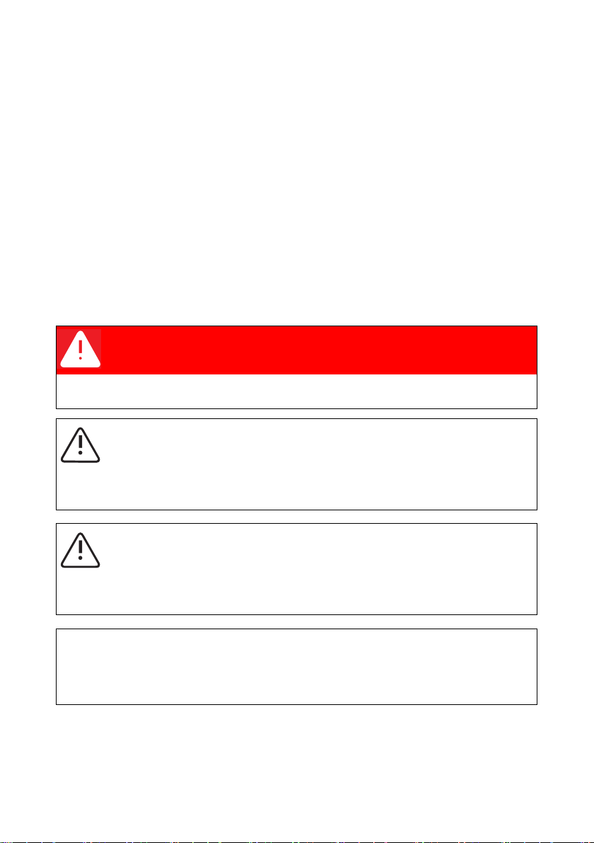
Warnings in this document
A warning describes a hazard to equipment or personnel. It calls attention to a procedure or practice,
which, if not correctly performed or adhered to, could result in damage to or destruction of part or all
of the SMA equipment and/or other equipment connected to the SMA equipment or personal injury.
DANGER
DANGER indicates a hazardous situation which, if not avoided, will result in death or
serious injury.
WARNING
WARNING indicates a hazardous situation which, if not avoided, could result in death or
serious injury.
CAUTION
CAUTION indicates a hazardous situation which, if not avoided, could result in minor or
moderate injury.
NOTICE
NOTICE is used to address practices not related to personal injury.
4 SC250U_GFDI-IUS101711 Installation Guide
Page 5

SMA America, LLC Important Safety Instructions
Other symbols in this document
In addition to the safety and hazard symbols described on the previous pages, the following symbol
is also used in this installation guide:
Information
This symbol accompanies notes that call attention to supplementary information that you
must know and use to ensure optimal operation of the system.
Markings on this product
The following symbols are used as product markings with the following meanings.
Warning regarding dangerous voltage
The product works with high voltages. All work on the product must only be performed
as described in it‘s documentation.
Electric arc hazards
The product has large electrical potential differences between its conductors. Arc flashes
can occur through air when high-voltage current flows. Do not work on the product
during operation.
Beware of hot surface
The product can become hot during operation. Do not touch the product during
operation.
Observe the operating instructions
Read the documentation of the product before performing any work. Follow all safety
precautions and instructions as described in the documentation.
UL1741 is the standard applied by Underwriters Laboratories to the Sunny Central
250U to certify that it meets the requirements of the National Electrical Code
929-2000. IEEE 929-2000 provides recommendations regarding the proper equipment
and functionality necessary to ensure compatible operation when power generation is
connected to the power distribution grid.
®
and IEEE-
Installation Guide SC250U_GFDI-IUS101711 5
Page 6

General Warnings SMA America, LLC
General warnings
General warnings
All electrical installations must be done in accordance with the local codes and National
Electrical Code
®
ANSI/NFPA 70.
The Sunny Central 250U contains no user-serviceable parts except for the fans on the
bottom of the enclosure and the filters behind the fans as well as the handle covers on the
sides of the unit. For all repair and maintenance, always return the unit to an authorized
SMA Service Center.
Be for e in sta lli ng o r using the Sun ny C ent ral 250 U, read all of the instructions, cautions, and
warnings on the Sunny Central 250U in this installation guide.
Before co nnect ing the Sunny Cent ral 250U to the power d istribution grid, contact the local
power distribution grid company. This connection must be made only by qualified
personnel.
Wiring of the Sunny Central 250U must be made by qualified personnel only.
6 SC250U_GFDI-IUS101711 Installation Guide
Page 7

SMA America, LLC Table of Contents
Table of contents
1 Notes on this manual. . . . . . . . . . . . . . . . . . . . . . . . . . . . . . 9
1.1 Target group . . . . . . . . . . . . . . . . . . . . . . . . . . . . . . . . . . . . . . . . 9
1.2 Syntax. . . . . . . . . . . . . . . . . . . . . . . . . . . . . . . . . . . . . . . . . . . . . 9
2 Safety . . . . . . . . . . . . . . . . . . . . . . . . . . . . . . . . . . . . . . . . . 10
3 List of materials. . . . . . . . . . . . . . . . . . . . . . . . . . . . . . . . . . 11
4 Removal of the components . . . . . . . . . . . . . . . . . . . . . . . 12
4.1 Overview . . . . . . . . . . . . . . . . . . . . . . . . . . . . . . . . . . . . . . . . . 12
4.2 Remove transparent cover . . . . . . . . . . . . . . . . . . . . . . . . . . . . 13
4.3 Remove flexible busbars . . . . . . . . . . . . . . . . . . . . . . . . . . . . . . 13
4.4 Remove the cable from the GFDI fuse . . . . . . . . . . . . . . . . . . . 14
5 Mounting the components. . . . . . . . . . . . . . . . . . . . . . . . . 15
5.1 Mount flexible busbar. . . . . . . . . . . . . . . . . . . . . . . . . . . . . . . . 15
5.2 Attach the cable to the GFDI fuse. . . . . . . . . . . . . . . . . . . . . . . 16
5.3 Attach markings . . . . . . . . . . . . . . . . . . . . . . . . . . . . . . . . . . . . 16
5.4 Check all connections. . . . . . . . . . . . . . . . . . . . . . . . . . . . . . . . 16
5.5 Attach transparent cover. . . . . . . . . . . . . . . . . . . . . . . . . . . . . . 17
5.6 Commissioning . . . . . . . . . . . . . . . . . . . . . . . . . . . . . . . . . . . . . 17
Installation Guide SC250U_GFDI-IUS101711 7
Page 8

Table of Contents SMA America, LLC
8 SC250U_GFDI-IUS101711 Installation Guide
Page 9

SMA America, LLC Notes on this manual
1 Notes on this manual
This manual describes the modification of a Sunny Central 250U from GFDI negative groundig to
GFDI positive grounding. This manual does not cover any details concerning PV modules. All relevant
information is available from the respective manufactures.
Keep this manual in a convenient place for future reference.
1.1 Target group
This manual is for qualified personnel only. Qualified personnel have received training and have
demonstrated skills and knowledge in the construction and operation of the device. Qualified
personnel are trained to deal with the dangers and hazards involved in installing electric devices.
1.2 Syntax
In this document the Sunny Central 250U is referred to in the following as Sunny Central.
In this document SMA America Production, LLC is referred to in the following as SMA.
Installation Guide SC250U_GFDI-IUS101711 9
Page 10

Safety SMA America, LLC
2 Safety
DANGER!
During operation, high voltages are present in the Sunny Central.
Death from electric shock will result.
When working on the Sunny Central, the device must be disconnected form the power
supply and tested for absence of voltage. Be sure to observe the five safety rules for
working on electrical systems.
The five safety rules for working on electrical systems are listed below:
• Switch off the system.
• Ensure that the device cannot be reconnected.
• Wait at least 5 minutes for all internal power supplies to discharge.
• Test for absence of voltage.
• Ground and short-circuit.
•Prevent access to neighboring systems.
CAUTION
Danger of crushing results from falling components.
• Wear personal protective equipment while working on the Sunny Central.
10 SC250U_GFDI-IUS101711 Installation Guide
Page 11

SMA America, LLC List of materials
3 List of materials
Quantity Description Equipment label
1 Flexible busbar 10x32x1 BK 320qmm (Cu rail, fuses)
7 Adhesive label DC1 Adhesive label DC+
1 Marking (equipment label) for the components WL+
1 Marking (equipment label) for the components WL1 Marking „This unit is grounded at the positive DC leg.”
1 Marking „max. 600 V DC PV+”
1 Marking „max. 600 V DC PV-”
Installation Guide SC250U_GFDI-IUS101711 11
Page 12

Removal of the components SMA America, LLC
4 Removal of the components
4.1 Overview
Position Description
A Position of the DC+ and DC‒ busbars and the contactor.
12 SC250U_GFDI-IUS101711 Installation Guide
Page 13

SMA America, LLC Removal of the components
4.2 Remove transparent cover
In order to reach the busbars, remove the transparent cover.
1. Remove all screws of the transparent cover.
2. Remove the transparent cover.
3. Put the screws and the transparent cover aside.
The transparent cover and the screws will be reused
later.
☑ The transparent cover is removed.
4.3 Remove flexible busbars
Between contactor K2 and busbar WL+ is a flexible
busbar 10 x 32 x 1.
1. Remove the 2 screws of the flexible busbar.
2. Remove the flexible busbar.
3. Put the flexible busbar aside. The flexible busbar
will not be reused.
☑ The flexible busbar between the contactor K2 and busbar WL+ is removed.
Installation Guide SC250U_GFDI-IUS101711 13
Page 14

Removal of the components SMA America, LLC
A flexible busbar 10 x 32 x 1 connects the contactor K2
and busbar WL‒.
1. Remove the 2 screws of the flexible busbar.
2. Remove the flexible busbar.
The flexible busbar will be reused later.
☑ The flexible busbar between contactor K2 and busbar WL- is removed.
4.4 Remove the cable from the GFDI fuse
1. Remove the screw that attaches the cable from the
GFDI fuse to busbar WL‒.
☑ The cable from the GFDI fuse is removed.
14 SC250U_GFDI-IUS101711 Installation Guide
Page 15

SMA America, LLC Mounting the components
5 Mounting the components
5.1 Mount flexible busbar
1. Connect busbar WL+ and the contactor K2:2 with
the provided flexible busbar 10 x 32 x 1:
Tighten the screws with a torque of 55ft-lb
(74Nm) at busbar WL+.
Tighten the screws with a torque of 62.5ft-lb.
(85Nm) at the contractor.
2. Connect busbar WL‒ and contactor K2:4 with the
flexible busbar 10 x 32 x 1.
3. Tighten the screws with a torque of 62.5ft-lb.
(85Nm) at the contractor and a torque of 55ft-lb.
(74Nm) at busbar WL‒.
Installation Guide SC250U_GFDI-IUS101711 15
Page 16

Mounting the components SMA America, LLC
5.2 Attach the cable to the GFDI fuse
1. Attach the cable from the GFDI fuse to busbar
WL‒.
2. Tighten the screw with a torque of 55ft-lb.
(74Nm).
5.3 Attach markings
1. Attach the label DC– to connection terminal X2
2. Position label „max. 600V DC PV–“ over
„max.600V DC PV+“.
3. Position label „This Unit is grounded at the positive
DC leg.“ over „This Unit is grounded at the negative
DC leg.“
4. Position label „max. 600V DC PV+“ over
„max.600V DC PV–“.
5. Atach the label DC+ to busbar WL–.
6. Atach the label WL+ to busbar WL–.
7. Atach the label DC– to busbar WL+.
8. Atach the label WL– to busbar WL+.
☑ The markings are attached.
5.4 Check all connections
1. Make sure that all electric and non-electric connections are attached securely.
2. Make sure that all screws are tightened with the specified torques.
16 SC250U_GFDI-IUS101711 Installation Guide
Page 17

SMA America, LLC Mounting the components
5.5 Attach transparent cover
Reattach the transparent cover. Tighten the 6 screws at
the cover.
5.6 Commissioning
Commission the Sunny Central after modification as described in the installation guide and check the
function of the Sunny Central.
Installation Guide SC250U_GFDI-IUS101711 17
Page 18

Page 19

Page 20

4.""NFSJDB--$
XXXSMAANFSJDBDPN
 Loading...