

Page 1
EN
Central Inverter
SUNNY CENTRAL 200 / 250 / 350 / 500 / 560
User Manual
SC-BEN100262 | 98-4003362 | Version 6.2
Page 2

Page 3

SMA Solar Technology AG Table of Contents
Table of Contents
1 Notes on this Manual. . . . . . . . . . . . . . . . . . . . . . . . . . . . . . 7
1.1 Area of validity . . . . . . . . . . . . . . . . . . . . . . . . . . . . . . . . . . . . . . 7
1.2 Target Group . . . . . . . . . . . . . . . . . . . . . . . . . . . . . . . . . . . . . . . 7
1.3 Additional Information . . . . . . . . . . . . . . . . . . . . . . . . . . . . . . . . 7
1.4 Symbols Used . . . . . . . . . . . . . . . . . . . . . . . . . . . . . . . . . . . . . . . 8
2 Safety . . . . . . . . . . . . . . . . . . . . . . . . . . . . . . . . . . . . . . . . . . 9
2.1 Appropriate Usage. . . . . . . . . . . . . . . . . . . . . . . . . . . . . . . . . . . 9
2.2 Safety Instructions . . . . . . . . . . . . . . . . . . . . . . . . . . . . . . . . . . . 10
2.3 Identifying the Sunny Central . . . . . . . . . . . . . . . . . . . . . . . . . . 11
2.4 Operating Modes. . . . . . . . . . . . . . . . . . . . . . . . . . . . . . . . . . . 12
3 Grid Security Management. . . . . . . . . . . . . . . . . . . . . . . . 14
3.1 What are the requirements? . . . . . . . . . . . . . . . . . . . . . . . . . . . 14
3.2 Active Power Limitation . . . . . . . . . . . . . . . . . . . . . . . . . . . . . . . 14
3.3 The Solution from SMA Solar Technology . . . . . . . . . . . . . . . . 15
4 Control Elements . . . . . . . . . . . . . . . . . . . . . . . . . . . . . . . . 16
4.1 Overview . . . . . . . . . . . . . . . . . . . . . . . . . . . . . . . . . . . . . . . . . 16
4.2 Sunny Central . . . . . . . . . . . . . . . . . . . . . . . . . . . . . . . . . . . . . . 17
4.2.1 Indicator Lights . . . . . . . . . . . . . . . . . . . . . . . . . . . . . . . . . . . . . . . . . . . . . . . 17
4.2.2 Key switch . . . . . . . . . . . . . . . . . . . . . . . . . . . . . . . . . . . . . . . . . . . . . . . . . . . 17
4.2.3 AC Main Switch . . . . . . . . . . . . . . . . . . . . . . . . . . . . . . . . . . . . . . . . . . . . . . 17
4.2.4 Emergency Stop . . . . . . . . . . . . . . . . . . . . . . . . . . . . . . . . . . . . . . . . . . . . . . 18
4.3 Sunny Central Control . . . . . . . . . . . . . . . . . . . . . . . . . . . . . . . 19
4.3.1 Functions of the Control Buttons . . . . . . . . . . . . . . . . . . . . . . . . . . . . . . . . . . 20
4.3.2 Description of the Display Symbols. . . . . . . . . . . . . . . . . . . . . . . . . . . . . . . . 21
5 Menu . . . . . . . . . . . . . . . . . . . . . . . . . . . . . . . . . . . . . . . . . . 22
5.1 Display Messages During Operation . . . . . . . . . . . . . . . . . . . . 22
User Manual SC-BEN100262 3
Page 4

Table of Contents SMA Solar Technology AG
5.2 Menu Overview . . . . . . . . . . . . . . . . . . . . . . . . . . . . . . . . . . . . 22
5.2.1 Operating data. . . . . . . . . . . . . . . . . . . . . . . . . . . . . . . . . . . . . . . . . . . . . . . 22
5.2.2 Spot Values . . . . . . . . . . . . . . . . . . . . . . . . . . . . . . . . . . . . . . . . . . . . . . . . . . 23
5.2.3 Long-Term Data. . . . . . . . . . . . . . . . . . . . . . . . . . . . . . . . . . . . . . . . . . . . . . . 24
5.2.4 Device Set-up . . . . . . . . . . . . . . . . . . . . . . . . . . . . . . . . . . . . . . . . . . . . . . . . 24
5.3 Adjusting the Display Contrast . . . . . . . . . . . . . . . . . . . . . . . . . 26
5.4 Setting the Language . . . . . . . . . . . . . . . . . . . . . . . . . . . . . . . . 26
5.5 Changing the Date and Time . . . . . . . . . . . . . . . . . . . . . . . . . . 26
5.6 Enter Password . . . . . . . . . . . . . . . . . . . . . . . . . . . . . . . . . . . . . 27
5.7 Display Firmware Version . . . . . . . . . . . . . . . . . . . . . . . . . . . . . 27
5.8 Deleting the Daily Values of the Energy Yield. . . . . . . . . . . . . . 28
6 Measuring Channels . . . . . . . . . . . . . . . . . . . . . . . . . . . . . 29
6.1 Adding Further Measurement Channels . . . . . . . . . . . . . . . . . . 31
6.2 Resetting the Display of Measurement Channels to the Factory
Setting. . . . . . . . . . . . . . . . . . . . . . . . . . . . . . . . . . . . . . . . . . . . 31
6.3 Retrieving Measurement Data . . . . . . . . . . . . . . . . . . . . . . . . . 32
6.3.1 Retrieving Measurement Data at the Sunny Central Control . . . . . . . . . . . . 32
6.3.2 Retrieving Measurement Data via Sunny Data Control . . . . . . . . . . . . . . . . 32
6.4 Deleting Measurement Data. . . . . . . . . . . . . . . . . . . . . . . . . . . 33
7 Parameters . . . . . . . . . . . . . . . . . . . . . . . . . . . . . . . . . . . . . 34
7.1 Description of the Parameter Functions. . . . . . . . . . . . . . . . . . . 35
7.2 Default Parameter Settings . . . . . . . . . . . . . . . . . . . . . . . . . . . . 38
7.3 Changing Parameters . . . . . . . . . . . . . . . . . . . . . . . . . . . . . . . . 39
7.4 Resetting Parameters. . . . . . . . . . . . . . . . . . . . . . . . . . . . . . . . . 40
7.5 Saving Parameters . . . . . . . . . . . . . . . . . . . . . . . . . . . . . . . . . . 40
8 Sending Data . . . . . . . . . . . . . . . . . . . . . . . . . . . . . . . . . . . 41
8.1 Selecting Remote Info . . . . . . . . . . . . . . . . . . . . . . . . . . . . . . . . 41
8.2 Activating Email Reports . . . . . . . . . . . . . . . . . . . . . . . . . . . . . . 42
4 SC-BEN100262 User Manual
Page 5

SMA Solar Technology AG Table of Contents
8.3 Selecting Report Types to Send . . . . . . . . . . . . . . . . . . . . . . . . 42
8.3.1 Daily Report "System Info" . . . . . . . . . . . . . . . . . . . . . . . . . . . . . . . . . . . . . . 44
8.3.2 Hourly Report "Errors, Warnings and Events" . . . . . . . . . . . . . . . . . . . . . . . . 45
8.4 Entering or Changing an Email Address. . . . . . . . . . . . . . . . . . 46
8.5 Sending a Test Report. . . . . . . . . . . . . . . . . . . . . . . . . . . . . . . . 47
9 Analog Inputs . . . . . . . . . . . . . . . . . . . . . . . . . . . . . . . . . . . 48
9.1 Detecting External Sensors . . . . . . . . . . . . . . . . . . . . . . . . . . . . 49
9.2 Calculating Gain and Offset. . . . . . . . . . . . . . . . . . . . . . . . . . . 50
9.3 Configuring External Sensors . . . . . . . . . . . . . . . . . . . . . . . . . . 52
9.3.1 ExtSolIrr and ExtGloIrr . . . . . . . . . . . . . . . . . . . . . . . . . . . . . . . . . . . . . . . . . 52
9.3.2 Displaying Sensor Values . . . . . . . . . . . . . . . . . . . . . . . . . . . . . . . . . . . . . . . 53
9.4 Configuring External Messages . . . . . . . . . . . . . . . . . . . . . . . . 53
9.4.1 Setting ExtAlarm . . . . . . . . . . . . . . . . . . . . . . . . . . . . . . . . . . . . . . . . . . . . . . 53
9.4.2 Activating TmpExt C . . . . . . . . . . . . . . . . . . . . . . . . . . . . . . . . . . . . . . . . . . . 54
10 Active Power Limitation . . . . . . . . . . . . . . . . . . . . . . . . . . . 55
10.1 Procedure for Setting Active Power Limitation. . . . . . . . . . . . . . 55
10.2 Active Power Limitation via Grid Frequency . . . . . . . . . . . . . . . 57
11 Grid Monitoring . . . . . . . . . . . . . . . . . . . . . . . . . . . . . . . . . 58
11.1 Grid Connection after Fault Clearance. . . . . . . . . . . . . . . . . . . 58
11.2 Behavior of Grid Limits over Time when Breaches Occur. . . . . 59
11.3 Setting the Medium-Voltage Level
(applicable only to HE devices) . . . . . . . . . . . . . . . . . . . . . . . . 60
11.4 Disconnection Protection Ramp (DCRmp). . . . . . . . . . . . . . . . . 60
12 External Grid Monitoring Relay (optional) . . . . . . . . . . . 61
12.1 Overview of the Display and Control Elements . . . . . . . . . . . . 62
12.2 Display Messages. . . . . . . . . . . . . . . . . . . . . . . . . . . . . . . . . . . 63
12.3 Configuration . . . . . . . . . . . . . . . . . . . . . . . . . . . . . . . . . . . . . . 64
12.3.1 Changing from Automatic Mode to Configuration Mode . . . . . . . . . . . . . . 64
User Manual SC-BEN100262 5
Page 6

Table of Contents SMA Solar Technology AG
12.3.2 Access to Configuration . . . . . . . . . . . . . . . . . . . . . . . . . . . . . . . . . . . . . . . . 65
12.3.3 Parameters . . . . . . . . . . . . . . . . . . . . . . . . . . . . . . . . . . . . . . . . . . . . . . . . . . 66
12.3.4 Monitoring . . . . . . . . . . . . . . . . . . . . . . . . . . . . . . . . . . . . . . . . . . . . . . . . . . 66
12.4 Alarm Messages / Dealing with Errors. . . . . . . . . . . . . . . . . . . 72
12.4.1 Clear Alarm Signal . . . . . . . . . . . . . . . . . . . . . . . . . . . . . . . . . . . . . . . . . . . . 72
12.4.2 Interface . . . . . . . . . . . . . . . . . . . . . . . . . . . . . . . . . . . . . . . . . . . . . . . . . . . . 72
13 Islanding Detection (Anti-Islanding) . . . . . . . . . . . . . . . . . 73
14 Sunny Team (optional) . . . . . . . . . . . . . . . . . . . . . . . . . . . 74
14.1 Identification of Manager Device and Team Device . . . . . . . . 74
14.2 Display of Team Mode on the Sunny Central. . . . . . . . . . . . . . 74
14.3 Operating States of Sunny Team . . . . . . . . . . . . . . . . . . . . . . . 75
14.4 Team Status. . . . . . . . . . . . . . . . . . . . . . . . . . . . . . . . . . . . . . . . 76
14.5 Team Mode Interrupted . . . . . . . . . . . . . . . . . . . . . . . . . . . . . . 77
14.6 Disable Team Mode . . . . . . . . . . . . . . . . . . . . . . . . . . . . . . . . . 78
14.7 Enable Team Mode . . . . . . . . . . . . . . . . . . . . . . . . . . . . . . . . . 79
15 Troubleshooting and Problem Solving. . . . . . . . . . . . . . . 80
15.1 Fault Diagnosis . . . . . . . . . . . . . . . . . . . . . . . . . . . . . . . . . . . . . 81
15.1.1 Categories of Faults and Warnings . . . . . . . . . . . . . . . . . . . . . . . . . . . . . . . 81
15.1.2 Types of Faults and Warnings. . . . . . . . . . . . . . . . . . . . . . . . . . . . . . . . . . . . 81
15.1.3 Warnings . . . . . . . . . . . . . . . . . . . . . . . . . . . . . . . . . . . . . . . . . . . . . . . . . . . 82
15.1.4 Faults. . . . . . . . . . . . . . . . . . . . . . . . . . . . . . . . . . . . . . . . . . . . . . . . . . . . . . . 86
15.1.5 Events . . . . . . . . . . . . . . . . . . . . . . . . . . . . . . . . . . . . . . . . . . . . . . . . . . . . . . 93
15.2 Clearing Errors . . . . . . . . . . . . . . . . . . . . . . . . . . . . . . . . . . . . . 93
16 Contact . . . . . . . . . . . . . . . . . . . . . . . . . . . . . . . . . . . . . . . . 94
6 SC-BEN100262 User Manual
Page 7

SMA Solar Technology AG Notes on this Manual
1 Notes on this Manual
This manual describes the operation and troubleshooting of the Sunny Central with the aid of Sunny
Central Control. Store all accompanying documentation in the direct vicinity of the Sunny Central. This
must be available to operators and maintenance staff at all times
1.1 Area of validity
This manual applies to the following device types with a Sunny Central Control 03 from firmware
version 2.04.
• SC 100LV
• SC 125LV
• SC 150
• SC 200HE
• SC 200
• SC 250HE
• SC 250
• SC 350HE
• SC 350
• SC 500HE
• SC 560HE
1.2 Target Group
This manual is for the use of installers and operators of PV plants equipped with a Sunny Central.
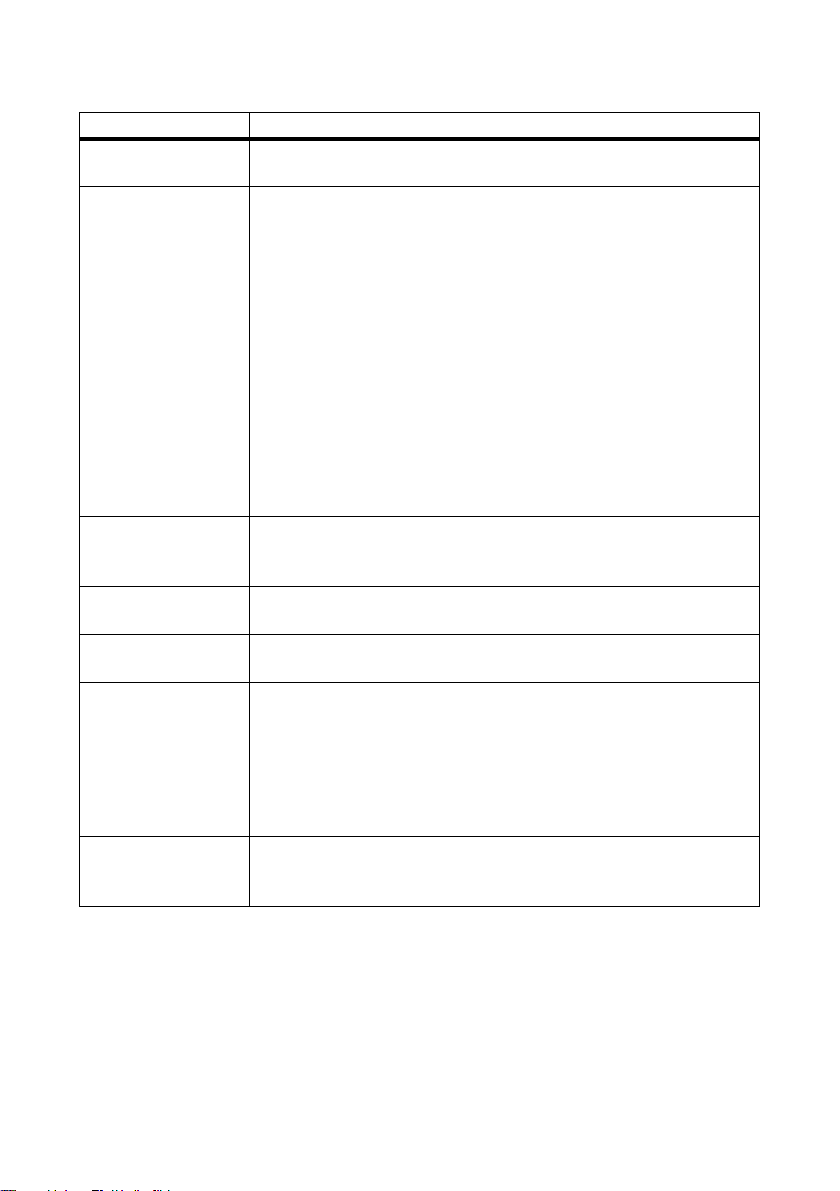
1.3 Additional Information
All manuals for the Sunny Central as well as for the installed components must be stored together with
the system documentation and must be accessible at all times. The documents listed below are
included in the delivery of your Sunny Central.
The following information is contained in these documents.
Installation guide Setup and installation of the Sunny Central
User Manual How to operate the Sunny Central and Sunny Central Control
Maintenance Manual Maintenance of the Sunny Central
Wiring diagrams Wiring diagrams of the Sunny Central
Accessory Documentation The documentation for optional accessories or optional equipment
for the Sunny Central (e.g. GFDI) can be found online at
www.SMA.de/en.
User Manual SC-BEN100262 7
Page 8
Notes on this Manual SMA Solar Technology AG
1.4 Symbols Used
The following types of safety precautions and general information are used in this manual:
DANGER!
DANGER indicates a hazardous situation which, if not avoided, will result in death or
serious injury.
WARNING!
WARNING indicates a hazardous situation which, if not avoided, could result in death or
serious injury.
CAUTION!
CAUTION indicates a hazardous situation which, if not avoided, could result in minor or
moderate injury.
NOTICE!
NOTICE indicates a situation which, if not avoided, could result in property damage.
Information
Information provides tips that are valuable for the optimal installation and operation of
your product.
8 SC-BEN100262 User Manual
Page 9
SMA Solar Technology AG Safety
A
B
C
2 Safety
2.1 Appropriate Usage
The Sunny Central is a PV inverter. It allows photovoltaic solar energy from PV modules to be
converted and fed into a medium-voltage grid.
The Sunny Central models SC 100LV, SC 125LV, SC 150, SC 200HE, SC 200, SC 250HE, SC 250,
SC 350HE, SC 350, SC 500HE and SC 560HE are equipped with the new grid security
management function. Further information on grid security management is provided in Section
3”Grid Security Management” (page14).
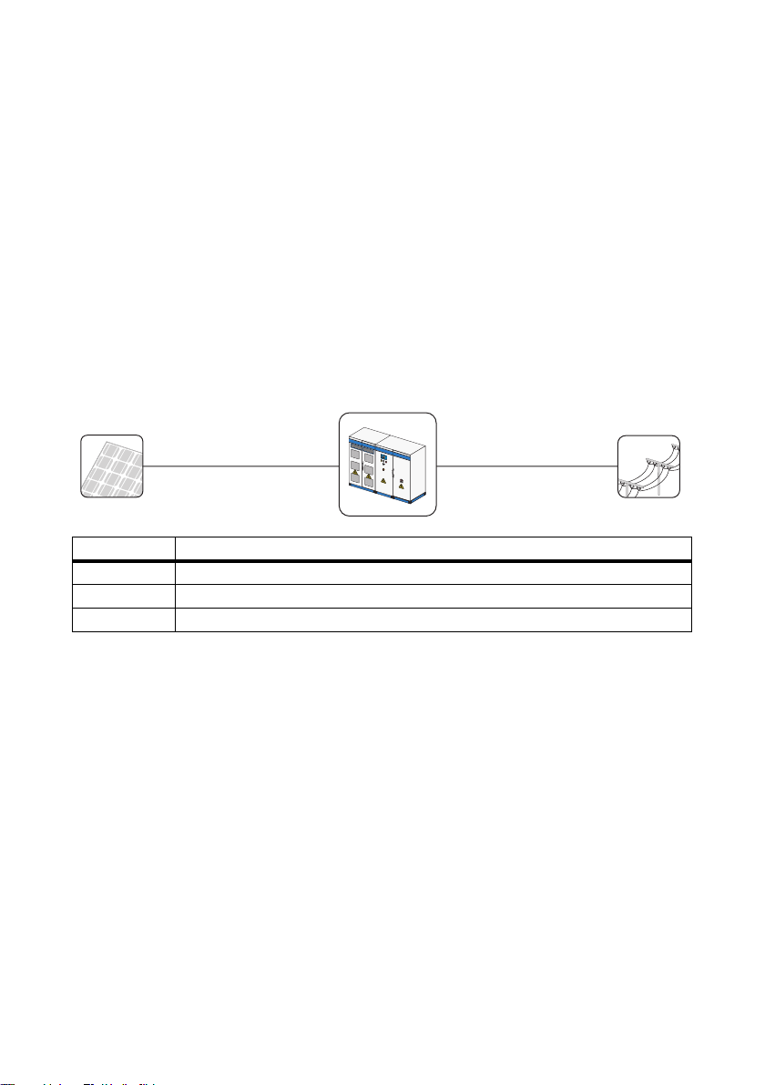
Principle of a grid-connected PV system with a Sunny Central
Object Description
APV Generator
BSunny Central
CPublic grid
Sunny Central
The Sunny Central is equipped with a low-voltage transformer, and feeds into the low-voltage grid.
Sunny Central HE
The Sunny Central HE does not have its own low-voltage transformer. It requires an adapted external
medium-voltage transformer via which it can feed into the grid.
Sunny Central LV
The Sunny Central LV feeds into the low-voltage grid. It is suitable for the connection of PV generators
with low voltage.
Sunny Central MV
The MV stations are medium-voltage stations. In an MV station, two Sunny Central HE devices feed
into the medium-voltage grid via a shared medium-voltage transformer.
User Manual SC-BEN100262 9
Page 10
Safety SMA Solar Technology AG
2.2 Safety Instructions
DANGER!
Contact with live components of the low voltage grid can be lethal! Death or
serious burns.
• Do not touch live components of the Sunny Central or the low-voltage grid.
• All safety precautions regarding the low-voltage grid must be observed.
DANGER!
Danger to life due to high voltages in the Sunny Central! Death or serious burns.
• Any work on the Sunny Central may be carried out by qualified electricians only.
• Work on the Sunny Central must only be carried out as described in this manual.
• Comply with all the listed safety instructions.
• All the safety instructions in the Sunny Central installation guide must be observed.
DANGER!
Danger to life due to damage to the Sunny Central. Death or serious burns.
Damage to the Sunny Central, e.g. defective cables, or a damaged enclosure, can lead to
death by electric shock or fire.
• Only operate the Sunny Central when it is in a technically faultless and safe
condition.
• Never operate a damaged Sunny Central.
• Check the Sunny Central regularly for visible damage.
• Regularly ensure that all external safety features are freely accessible at all times,
and that they function correctly.
10 SC-BEN100262 User Manual
Page 11
SMA Solar Technology AG Safety
A
A
A
2.3 Identifying the Sunny Central
Identify the Sunny Central by the serial number and the device type on the type plate. The type label
is situated on the inside of the door.
The serial number (A) is also located on the front side of
the Sunny Central.
User Manual SC-BEN100262 11
Page 12
Safety SMA Solar Technology AG
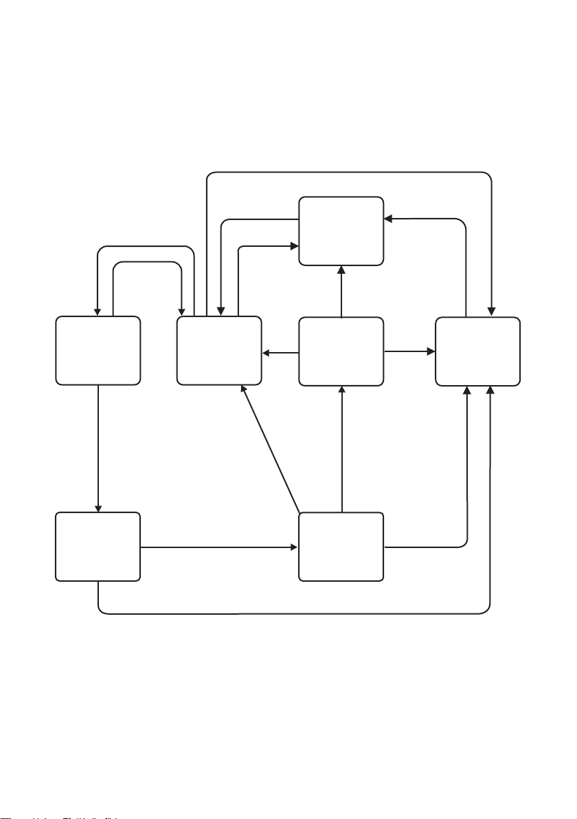
Failure
"Start" switch
Wait
Shutdown
"Stop"
Startup
MPP load
operation
Startup completed
Ppv < PpvStop
and T > TStop or
"Stop" switch
Failure
Failure
Failure
Failure
No fault
Grid
monitoring
"Stop"
Grid monitoring
time reached
Vpv > VpvStart
and T > TStart and grid
limits reached
Leave grid
limits
Stop
Leave grid
limits
2.4 Operating Modes
After switch-on, the Sunny Central runs through the different modes illustrated below. When switched
off, the Sunny Central is in the "Stop" mode. By turning the key switch, the Sunny Central goes into to
the "Wait" mode.
12 SC-BEN100262 User Manual
Page 13
SMA Solar Technology AG Safety
Operating mode Explanation
Stop The Sunny Central is switched off. The Sunny Central remains in this
condition until the key switch is turned to "Start".
Wait If the key switch is set to "Start", the Sunny Central goes into to the "Wait"
mode.
The start voltage "VpvStart" must be adjusted to conform to the PV
generator connected to the Sunny Central. Check and adjust the start
voltage as necessary.
If the input voltage is below the set start voltage "VpvStart", the Sunny
Central remains in "Wait" mode. The value for "VpvStart" is shown in the
display of Sunny Central Control.
If the input voltage is higher than the start voltage "VpvStart", the Sunny
Central waits until the time defined in the parameter "TStart" has elapsed.
If the input voltage has not fallen below the start voltage "VpvStart" during
this p eriod, the Sunny Cen tral checks whether there is connection to the AC
grid. If there is a valid AC grid connection, the AC contactor clos es and t he
Sunny Central transfers to grid monitoring.
Grid Monitoring The grid is monitored for adherence to grid limits for the monitoring time
"GriGrdMonTm". If the grid limits are not exceeded during this time, the
Sunny Central goes into the "Startup" mode.
Startup After completing grid monitoring, the Sunny Central navigates to its first
operating point and commences grid feed.
MPP load operation In MPP operation the Sunny Central feeds power to the grid and operates
continuously at the maximum power point (MPP).
Shutdown The Sunny Central shuts down (switches off) in the following cases:
• The power measured during the time interval "TStop" is less than
"PpvStop".
• A failure has occurred which necessitates shutdown of the Sunny
Central.
• The key switch is set to "Stop".
Failure If a fault occurs during operation, the Sunny Central shuts down and the
Sunny Central Control displays the fault. You will find a list of faults in
section 15”Troubleshooting and Problem Solving” (page80).
User Manual SC-BEN100262 13
Page 14

Grid Security Management SMA Solar Technology AG
3 Grid Security Management
3.1 What are the requirements?
In Germany, PV systems with an installed capacity of more than 100 kWp must participate in feed
and grid security management. First and foremost, the utility operator must be able to limit the power
of the PV system by remote control, and temporarily reduce it to zero i n critical cases. Releva nt cont rol
commands from the utility operator must therefore be transmitted quickly and reliably to the Sunny
Central.
The requirements in detail
• Reception of the setpoint via a centralized ripple control signal receiver with 2 or 4 relays.
• Limitation of the feed-in power in 4 configurable stages (for example, 0 % / 30 % / 60 % /
100 % of the agreed installed active power P
• Setting of the required setpoint in less than a minute.
3.2 Active Power Limitation
Under certain circumstances, the grid operator is entitled to dictate a temporary limitation of feed-in
power or to implement a system shutdown. According to the Medium-Voltage Directive, generator
systems must be able to reduce their active power in stages of no more than 10 % of the agreed
installed active power P
the connected system power have become standard practice.
. However, the four staged reductions of 100 %, 60 %, 30 % and 0 % of
AV
AV
).
14 SC-BEN100262 User Manual
Page 15
SMA Solar Technology AG Grid Security Management
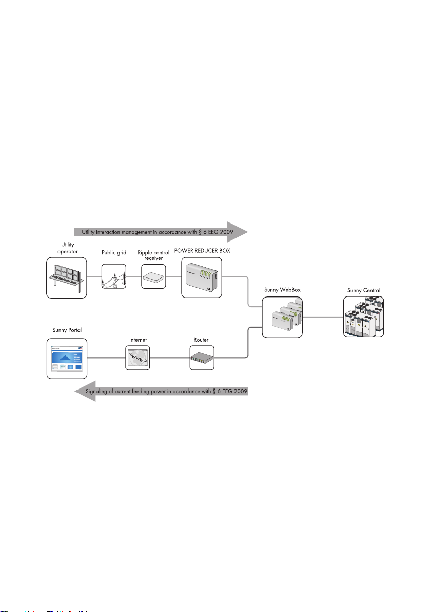
3.3 The Solution from SMA Solar Technology
With the Power Reducer Box it is possibl e to imp lement active power limitation in accordance with the
requirements of grid security management (GSM) for a PV system.
To do this, four di gital stat es (e.g. of a radio ripple contro l receiver ) can be imported v ia the t he Pow er
Reducer Box, thus enabling the Sunny Central to be set according to the specifications of the utility
operator.
The four input ports are freely configurable via the integrated web interface. If a signal from the radio
ripple control receiver is present, the Power Reducer Box analyzes the signal and relays an instruction
via the Ethernet network to the registered Sunny WebBox devices.
Activated Sunny WebBox devices transfer the instruction to the connected Sunny Central.
Events are recorded onto the internal memory of the Power Reducer Box. In addition, it is possible to
write events onto an SD card or download events via the web interface.
h
Besides the Power Reducer Box, there are two further options for meeting the requirement of grid
security management. These are 1) reception of the signals via an analog input on the Sunny Central
and 2) manual setting of default values via parameters.
How to implement these options is described in this manual.
User Manual SC-BEN100262 15
Page 16
Control Elements SMA Solar Technology AG
A
B
C
D
E
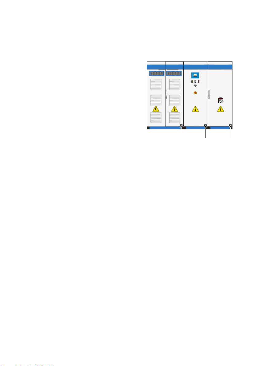
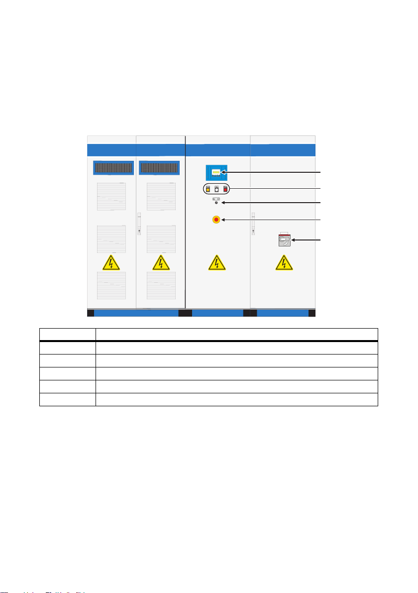
4 Control Elements
4.1 Overview
The following diagram shows the different control elements, based on the example of a
Sunny Central 250.
Object Description
A Sunny Central Control
B Indicator light (disturbance, warning, Sunny Team)
CKey switch
D Emergency shut-off with key
EAC Main Switch
16 SC-BEN100262 User Manual
Page 17
SMA Solar Technology AG Control Elements
4.2 Sunny Central
4.2.1 Indicator Lights
There are 2 indicator lights at the front of the Sunny Central. If an error occurs, these indicator lights
indicate the type of failure.
Meaning of the colors
Yellow: The Sunny Central is in "Alert" status. The Sunny Central does not switch off. Check the
system. Once the error is no longer active, the fault indication is automatically reset.
Red: The Sunny Central is in "Fault" status. If the Sunny Central has detected a fault, it will shut
down. Once the error has been rectified and cleared, it will resume operation. For more
information see Section 15.1.2”Types of Faults and Warnings” (page81).
4.2.2 Key switch
The key switch is used to switch the Sunny Central on and off. After turning the switch to the "Start"
position, the Sunny Central switches from the "Stop" mode to the "Wait" mode. Given sufficient
irradiation and a valid grid, the Sunny Central goes into grid feeding operation. If the irradiation, and
thus the input voltage, are too low, the Sunny Central remains in "Wait" mode.
When the key switch is turned to "Stop", the DC main switch is automatically switched off by a motor
drive.
4.2.3 AC Main Switch
NOTICE!
Improper use of the AC main switch may cause damage to the Sunny Central.
The components of the Sunny Central are subject to considerable stress if the AC main
switch is actuated under load. Frequent use of the AC main switch can cause stress-related
damage to individual components.
• Switch off the Sunny Central with the key switch.
• Operate the AC main switch.
The AC main switch enables you to disconnect the Sunny Central from the grid on the AC side.
User Manual SC-BEN100262 17
Page 18
Control Elements SMA Solar Technology AG
4.2.4 Emergency Stop
NOTICE!
Improper use of the emergency shut-off switch may cause damage to the Sunny
Central.
The components of the Sunny Central are subject to considerable stress if the emergency
shut-off switch is actuated under load. Frequent use of the emergency shut-off switch can
cause stress-related damage to individual components.
• Only use the emergency shut-off switch in an emergency.
• Switch off the Sunny Central with the key switch.
The emergency shut-off switch immediately disconnects the Sunny Central from the grid and the PV
generator, thus putting the Sunny Central in a safe state.
By pressing the emergency shut-off switch, the device is locked in the "Off" position. The emergency
shut-off switch can only be deactivated with the appropriate key. In addition, the activation of the
emergency shut-off switch must be cleared using Sunny Central Control or Sunny Data Control.
You can install an external emergency shut-off switch on each Sunny Ce ntr al o r co nne ct s eve ral Sunny
Centrals via a shared emergency shut-off switch.
18 SC-BEN100262 User Manual
Page 19
SMA Solar Technology AG Control Elements
A
B
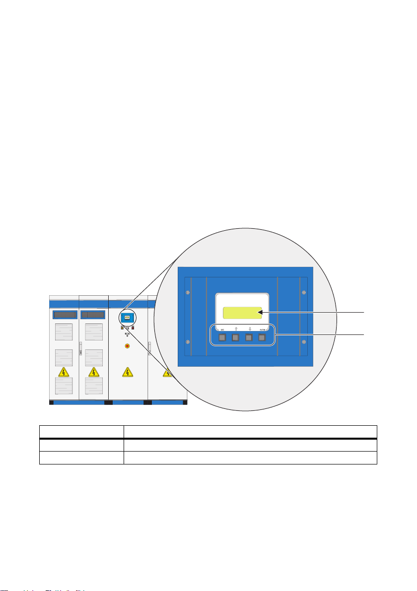
4.3 Sunny Central Control
Sunny Central settings can be adjusted by means of the Sunny Central Control. The functions
performed by Sunny Central Control can be summarized as follows:
• Control of the Sunny Central operation
• Display of current measured values
• Changing the parameters of the Sunny Central
• Maximum power point (MPP) tracking
• Collection and archiving of measurement data
• Remote access capability with NET Piggy-Back
• Connection of external sensors
The Sunny Central Control is mounted at eye level on the Sunny Central. The Sunny Central Control
is operated by means of four control buttons. These buttons are situated beneath the 4-line display.
Object Description
A4-line display
B Control buttons
User Manual SC-BEN100262 19
Page 20
Control Elements SMA Solar Technology AG
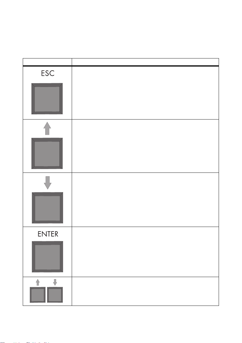
4.3.1 Functions of the Control Buttons
The control buttons have several functions. The buttons and their functions are described in the
following table.
Button Description / Function
ESC
• Cancels / exits function
• Answers questions with "No"
• Returns to the previous menu
• Changes from the standard view to the main menu
Upward arrow
• Moves to line above
• Increases value
Downward arrow
• Moves to line below
• Decreases value
ENTER
• Selects a function from the menu
• Selects a value
• Confirms changes
• Answers questions with "Yes"
Upward arrow + downward arrow
• Returns to standard view
20 SC-BEN100262 User Manual
Page 21
SMA Solar Technology AG Control Elements
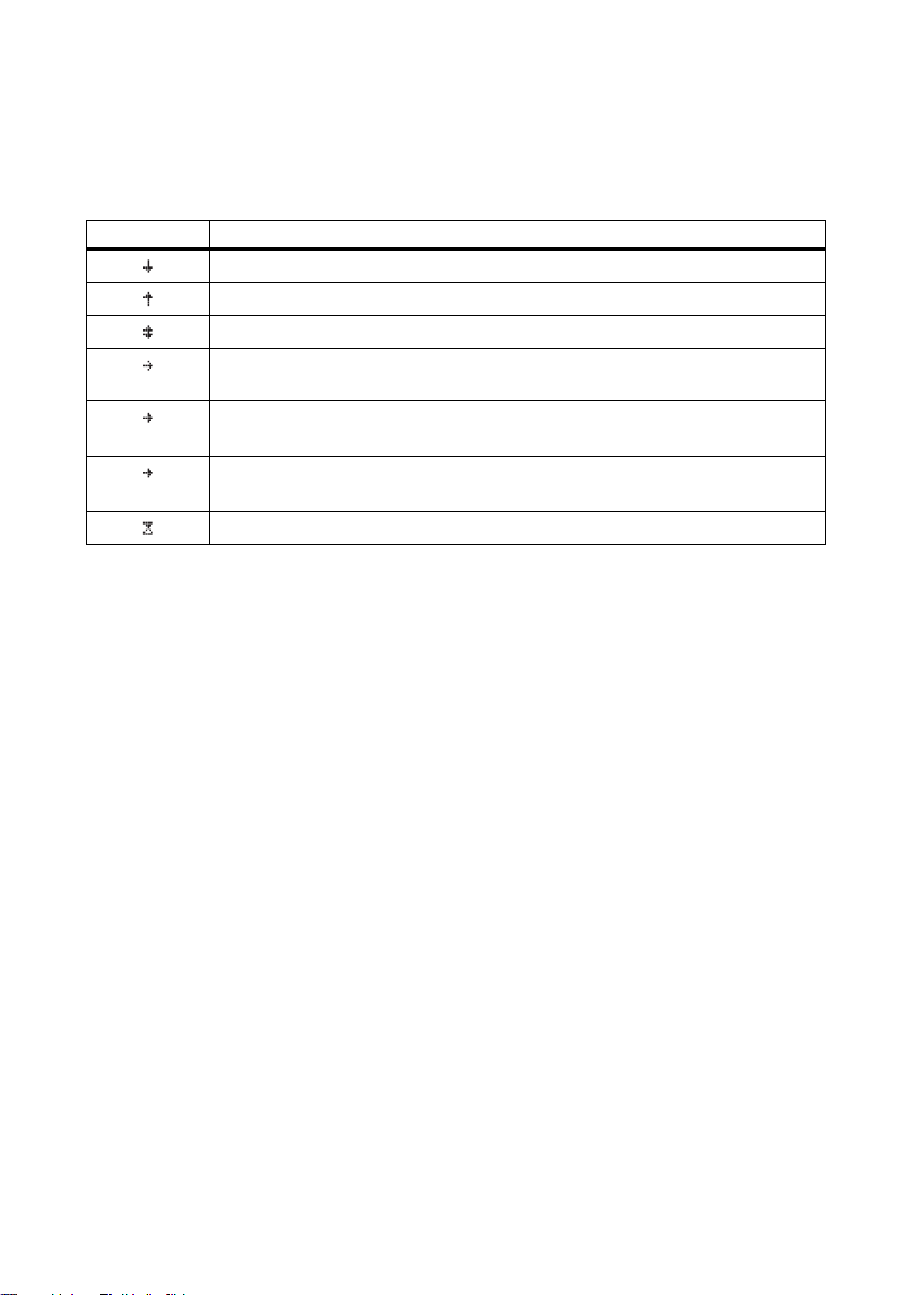
4.3.2 Description of the Display Symbols
The Su nny Cen tral Contr ol display has four l ines. I t uses various display symbols, which are explained
in the following table.
Symbol Description
There are more display lines below
There are more display lines above
There are more display lines above and below
Appears to the left of the currently selected line. Press [ ↑ ] or [ ↓ ] to move to
another line.
Appears to the left of a value which can be changed.
(lit)
If, for example, a parameter has been changed, the arrow to the left of the active
(blinking)
line blinks.
The Sunny Central Control is loading the next menu or saving data.
User Manual SC-BEN100262 21
Page 22
Menu SMA Solar Technology AG
5 Menu
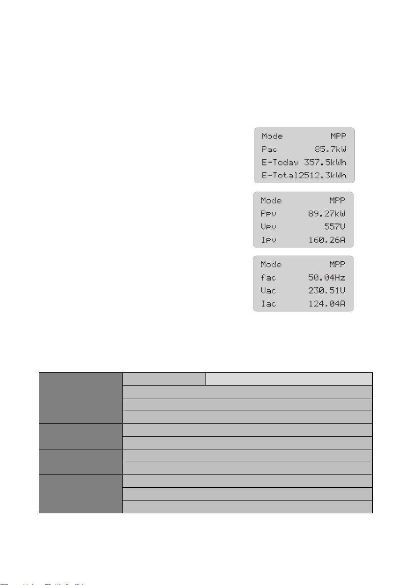
5.1 Display Messages During Operation
After the Sunny Central has been switched on, the Sunny Central Control initializes. Initialization
involves a sequence of three display messages.
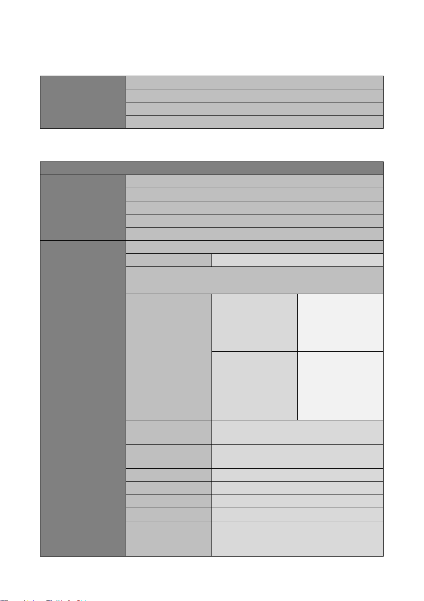
After initialization the Sunny Central displays the
measured values and spot values shown to the right.
You can switch between the three views with the buttons
[ ↑ ], [ ↓ ] or [ENTER]. If a warning or fault is reported,
the display will alternate between the active standard
view and the error with the highest priority.
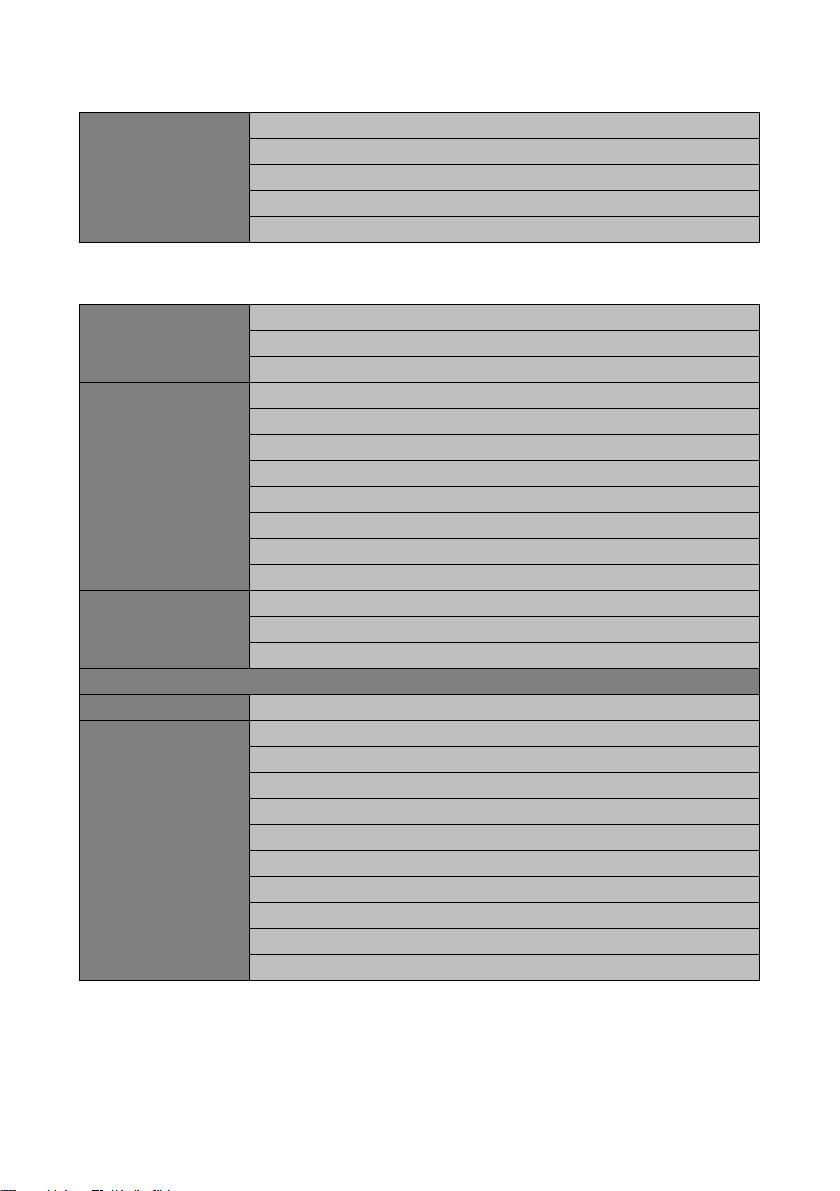
5.2 Menu Overview
5.2.1 Operating data
Faults Current Faults SC Quit Function
BFR Error
Stack Failure
Err Meas. DC
Plant Status State
Inverter Status
Energy Yield E-Total
E-Today
Data files Meas. Interval
Daily Values
Meas. Channels
22 SC-BEN100262 User Manual
Page 23
SMA Solar Technology AG Menu
Other h-On
Working Time
Startup counter
Fault counter
Alert counter
5.2.2 Spot Values
PV Ppv
Vpv
Ipv
Grid Pac
Qac
Sac
Fac
Iac
Vac L1-L2
Vac L2-L3
Vac L3-L1
Red.effect.pow. P-WSpt
P-WModFailStt
P-WModStt
Outp.react.pow. (displayed but not supported)
Grid decoupling GriGrdStt
Other T-Heat Sink C
Mppsearchcount
Team status
R-Insul
TmpInt C
TmpExt C
ExtSolP
ExtSolQ (displayed but not supported)
ExtSolIrr
ExtGloIrr
User Manual SC-BEN100262 23
Page 24
Menu SMA Solar Technology AG
5.2.3 Long-Term Data
Long-Term Data Meas. Chn.
Energy Yield
Plant Status
Faults
5.2.4 Device Set-up
Password
System Language
Date/Time
Inverter Type
Firmware
BFR_SW_Vers.
Parameters Param. Function
Red.effect.pow. P-WMod, P-W, P-WNom, Plimit, Pmax, Smax
Outp.react.pow.
(displayed but not supported)
Grid decoupling Voltage VRtg, VCtlhhLim,
VCtlhhLimTm, VCtlhLim,
VCtlhLimTm, VCtllLim,
VCtllLimTm, VCtlllLim,
VCtlllLimTm
Grid frequency HzRtg, HzCtlhhLim,
HzCtlhhLimTm,
VCtlhLim, VCtlhLimTm,
VCtllLim, VCtllLimTm,
VCtlllLim, VCtlllLimTm,
HzCtlMin, HzCtlMinTm
Grid connection GriGrdMonTm, VCtlOpMinNom,
VCtlOpMaxNom, HzCtlOpMin, HzCtlOpMax
Mpp Limit Val. UmppMin, dUreference, PsearchMpp,
TsearchMpp
Mpp Tracking dUtrack, TcheckMpp, Mpp Factor, TrackCnt
Start requiremt. Operating Mode, VpvStart, Tstart
Shut-down requ. PpvStop, Tstop
Grid Monitor. PpvMinCheck
Other E-Total Offset, TMax. cabinet, TMin. cabinet,
Team function, P-Next Team, P-Prv. Team, Tau-FP,
Test.feed.unit, Date availab., TmpDrtStopMod
24 SC-BEN100262 User Manual
Page 25
SMA Solar Technology AG Menu
Interfaces Communication COM1:SMUs Medium, Baud rate,
Protocol
COM2: Inverter Medium, Baud rate,
Protocol, Registration,
Detection, Parameters,
Measured values
COM3: PC Medium, Baud rate,
Protocol
Analog In ExtSolP, R-Insul, ExtSolIrr, ExtGloIrr, ExtAlarm,
ExtSolQ (displayed but not supported), TmpExt C
Digital In Digital Input 1 - 8
Digital Out +Diag Ext+24V, +Diag DOut, Dig. Output 1 - 8
Data archives Data Recording
Meas. Interval
Max. Storage
Chan. Select.
SMUs Devices Registration, Detection, Parameters, Measured
Values
Parameters regist. SMUs, Error Report Time, Polling Time,
SMU_Overnight Shutdown, SMU_Theft,
Tolerance Grp1 - 3
Measured Values mean value Grp1 - 3
Failure Actual Failures, Hist. failures
NET/EMAIL NET KO_NET, KO_NET-ETH IP, NET-ETH SNET,
KO_NET-ETH PVSN, NET-ETH GW,
NET-ETH DNS
Remote-Info EMAIL
Events Plant info, warnings,
errors, daily report at
Recipient Company/Name,
EMAIL TO, EMAIL
CC1, EMAIL CC2
Sender Plant Name, EMAIL
FROM
ISP Account ISP Phone No., ISP
User, ISP Pass
SMTP Account SMTP Server, SMTP
User, SMTP Pass,
Default
Test Report
User Manual SC-BEN100262 25
Page 26
Menu SMA Solar Technology AG
[ Language ]
German
English
spanish
5.3 Adjusting the Display Contrast
You can adjust the display contrast in any menu. You need to use a two-button combination to
increase or decrease the contrast.
Button combination Function
[ESC] + [ ↑ ] Increases the contrast.
[ESC] + [ ↓ ] Decreases the contrast.
5.4 Setting the Language
You can choose between the languages German, English and Spanish. If you wish to change the
language setting, proceed as follows:
1. Select „Device Set-up > System > Language“.
2. To select the required language press [ENTER] twice.
☑The required language is now set.
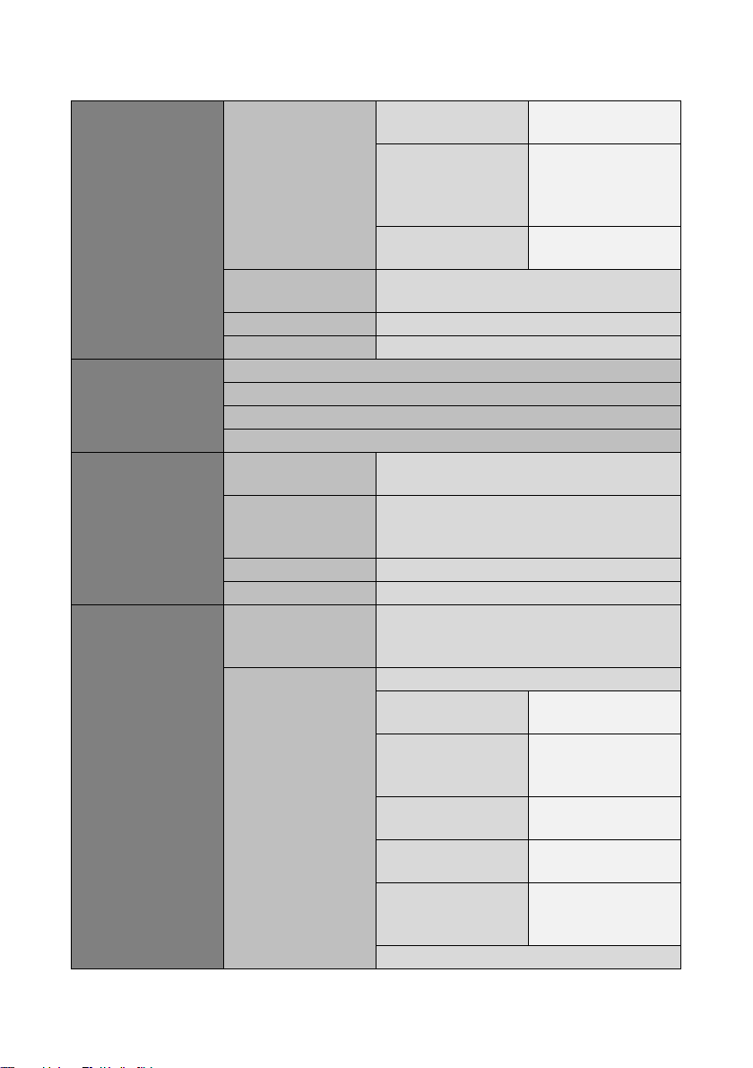
5.5 Changing the Date and Time
The Sunny Central Control's default settings for date and time correspond to the Central European
time zone. In order to change the date or the time proceed as follows:
1. Select "Device Set-up > System > Date/Time".
2. Click on the date.
3. Set the required date (day, month and year ) with the [ ↑ ] or [ ↓ ] buttons and confirm each
value setting with [ENTER].
4. Press [ENTER] twice to confirm the date as a whole.
☑ The required date has been set.
5. Click on the time.
6. Set th e requi red ti me (hours and mi nutes) with the [ ↑ ] or [ ↓ ] buttons and c onfirm each value
setting with [ENTER].
7. Press [ENTER] twice to confirm the time as a whole.
☑ The required time has been set.
☑ Date and time have now been changed.
26 SC-BEN100262 User Manual
Page 27
SMA Solar Technology AG Menu
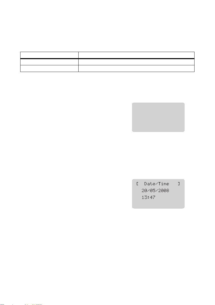
5.6 Enter Password
Safety-relevant Sunny Central parameters can only be adjusted after entering a password. You can
obtain a password from our Serviceline (see Section 16”Contact” (page94)).
Proceed as follows to enter the password:
1. Select "Device Set-up > Password".
2. Enter the password with the [ ↑ ] or [ ↓ ] buttons and confirm the set value with [ENTER].
☑ After confirmation, the entered values are displayed as a row of asterisks.
☑ The Sunny Central Control beeps 3 times if the correct password has been entered. If the
password is incorrect, the Sunny Central Control beeps once.
Locking the Sunny Central Control
You can lock the Sunny Central Control under "Device Set-up > Password", by entering an
incorrect password, or no password.
Password protection will automatically resume at midnight, or after a restart of Sunny
Central Control.
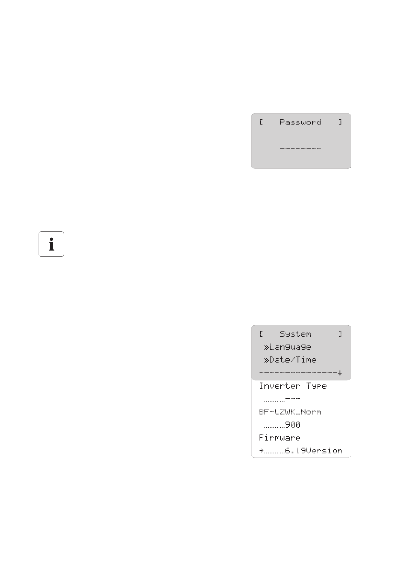
5.7 Display Firmware Version
You can view the firmware version on Sunny Central
Control under "Device Set-up > System > Firmware".
User Manual SC-BEN100262 27
Page 28
Menu SMA Solar Technology AG
5.8 Deleting the Daily Values of the Energy Yield
The daily values of the energy yield can be displayed on the Sunny Central Control under "Long-Term
Data > Energy Yield". The daily values are sorted according to the month. A list of daily energy yields
is displayed upon selecting the required month by pressing [ENTER].
You can delete the daily energy yield values as described below:
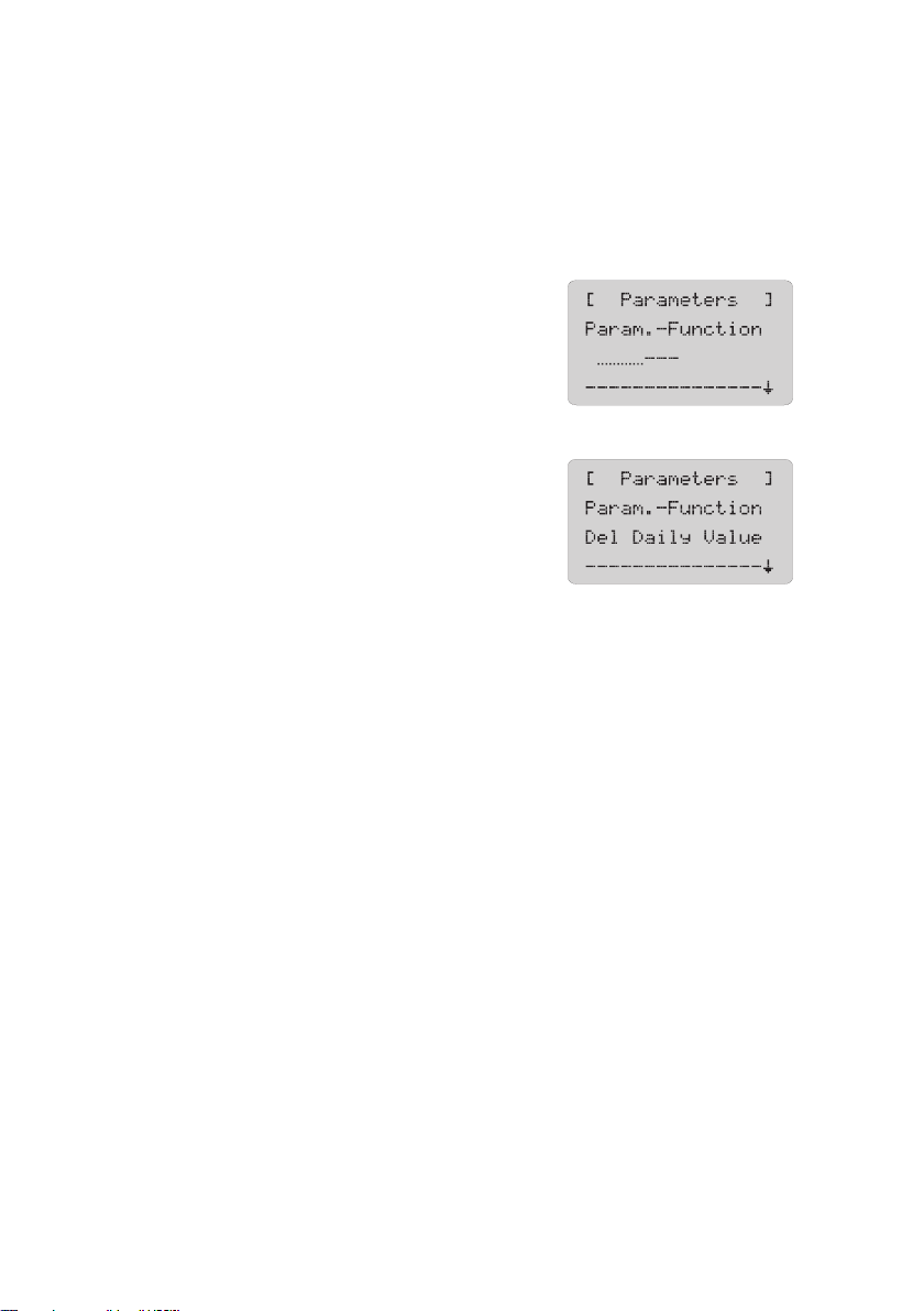
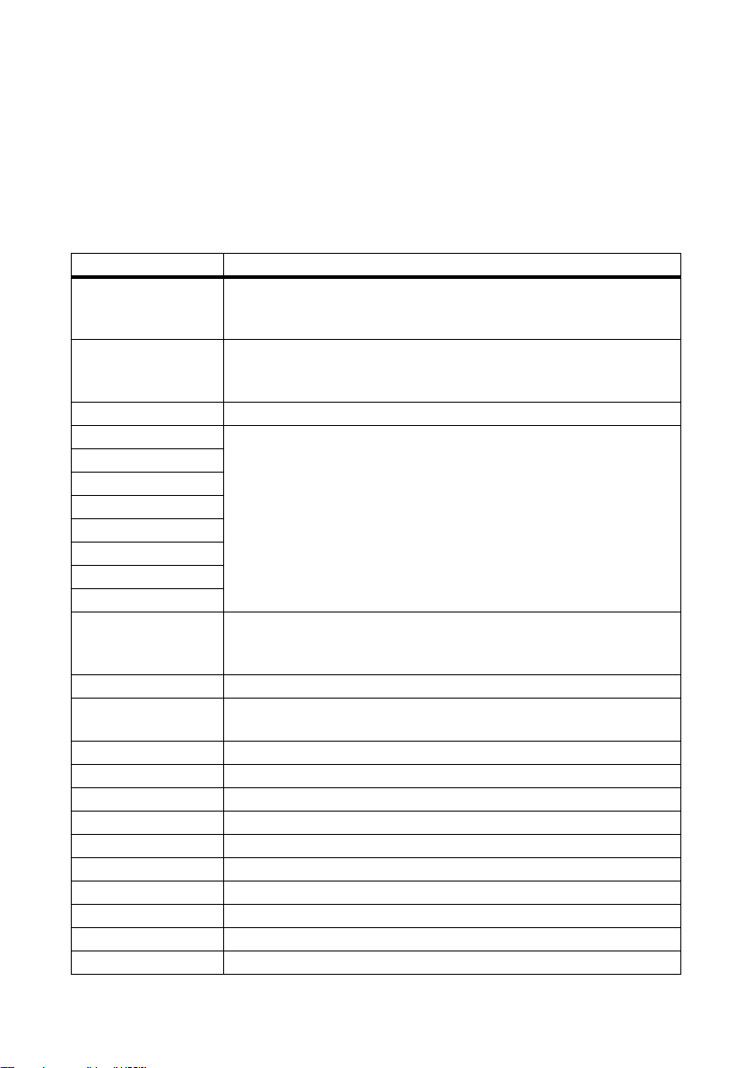
1. Select "Device Set-up > Parameters >
Param.-Function".
☑ The display blinks.
2. Select "Del Daily Value" with the [ ↓ ] button and
confirm by pressing [ENTER ].
☑ The daily energy yield values have now been reset
to the factory setting.
28 SC-BEN100262 User Manual
Page 29
SMA Solar Technology AG Measuring Channels
6 Measuring Channels
Yo u ca n us e th e Su nny Cen tral Con tro l to dis pla y di ffe ren t me asurement channels. To do this, proceed
as described in Section 6.3”Retrieving Measurement Data” (page32).
All the measurement channels are described in the following table. The measurement channels
marked with an * are preset in the factory and are standardly displayed in the Sunny Central Control
under "Long-Term Data > Meas. Chn. > SC...SCXXX".
Measuring channel Description
+Diag DOut The measurement channel can only be seen after the installer password
has been entered. Status of the digital output "+Diag DOut"
(Status: Fault, Okay)
+Diag Ext+24V The measurement channel can only be seen after the installer password
has been entered. Status of the digital output "+Diag Ext+24V"
(Status: Fault, Okay)
Startup counter Counter for the number of times the system has started up.
Digital Input 1 Status of digital inputs 1 to 8
Digital Input 2
Digital Input 3
Digital Input 4
Digital Input 5
Digital Input 6
Digital Input 7
Digital Input 8
E-Today Energy which the Sunny Central has fed into the grid today. This is the
energy generated from the time the Sunny Central starts operating in the
morning to the moment of the reading.
Error * Error of the Sunny Central.
E-Total Total energy which the Sunny Central has fed into the grid during its
operating time.
ExtGloIrr Analog input - external pyranometer (optional)
ExtSolIrr Analog input - external irradiation sensor (optional)
ExtAlarm Analog input - external temperature sensor (optional)
ExtSolP Analog input - external setpoint specification of active power
ExtSolQ This measuring channel is displayed but not supported.
Fac Grid frequency
FI Code Response code of the NET Piggy-Back
FI Status Status of the connection setup to the NET Piggy-Back
h-On * Total number of operating hours
h-Total * Total number of operation hours with grid feed
User Manual SC-BEN100262 29
Page 30

Measuring Channels SMA Solar Technology AG
Measuring channel Description
Iac Grid output current
Ipv * DC input current
Comm.fault SMU Faulty communication with Sunny String-Monitor No.
Meas. Data Counter for the number of times an entry is saved in the circular buffer.
Mean value Grp1 Mean value of the str ing current s of Sun ny S tri ng-Monitor group 1 to Sunny
Mean value Grp2
String-Monitor group 3
Mean value Grp3
Mode * Sunny Central operating mode (e.g. MPP)
Mppsearchcount Counter for the number of times the system changed to MPP Search.
Pac * Grid output power of the des Sunny Central
Pac smoothed Smoothed feed-in power.
Ppv DC input power of the Sunny Central
P-WModStt * Display of the currently effective active power limit.
Qac * Reactive power
Reg. SMUs Number of registered Sunny String-Monitors
R-Insul * Isolation resistance
SMU Warncode The channel "SMU Warncode" displays a number code "xxyy" where xx:
denotes the number of the faulty Sunny String-Monitor (1 to 40) and yy the
er ror num ber 01 - 08: cha nne l nu mbe r fo r er ror in s tri ng c urr ent monitoring;
09 - 10: error in signaling contact monitoring
Fault counter Counter for the number of times a fault has occurred.
Team Status Status of Sunny Team
For more information, refer to Section 14.4”Team Status” (page76).
Cooler Temp. * Temperature of the heat sink
TmpExt C * Analog input of the external temperature sensor (optional)
TmpInt C Analog input of the internal temperature sensor (standard)
TStart Reverse Time remaining until the system starts up.
TWait Reverse Time remaining until the next plant start-up attempt
Vac L1-L2 * Grid output voltage L1-L2
Vac L2-L3 Grid output voltage L2-L3
Vac L3-L1 Grid output voltage L3-L1
Vpv * DC input voltage of the Sunny Central
Vpv0 * Open-circuit voltage of the PV plant
VpvSet DC setpoint input voltage
Warn. counter Counter for the number of times a warning has occurred.
30 SC-BEN100262 User Manual
Page 31

SMA Solar Technology AG Measuring Channels
6.1 Adding Further Measurement Channels
You can add further channels to the standard 14 measurement channels. To do this, proceed as
follows:
1. Select "Device Set-up > Data Archives > Chan. Select. > SC...SCCXXX".
☑ The Sunny Central Control displays all
measurement channels. The measurement
channels already displayed in the menu "Long-
Term Data > Meas. Chn. > SC...SCXXX" are
marked with a dot.
2. Select the measurement channel to be added with the [ ↓ ] button and confirm with [ENTER].
☑ A dot now appears in front of the selected measurement channel.
3. When exiting the menu, confirm changes with [ENTER].
☑ Further measurement channels have been added. To call up the measurement data, follow the
steps in Section 6.3”Retrieving Measurement Data” (page32).
6.2 Resetting the Display of Measurement Channels to the Factory Setting
The Sunny Central Control displays 14 measurement channels as standard. If you have added extra
channels to the display, it is possible to reset the display back to default. To do this, proceed as
follows:
1. Select "Device Set-up > Parameters > Param.
Function".
☑ The display blinks.
2. Select "default chan.".
☑ The display stops blinking.
3. Press [ENTER].
☑ The display of the measurement channels is now reset to the factory setting.
User Manual SC-BEN100262 31
Page 32

Measuring Channels SMA Solar Technology AG
6.3 Retrieving Measurement Data
All selected measurement channels and their measured values are recorded in the Sunny Central
Control. You can retrieve the measurement data directly at the Sunny Central Control or via Sunny
Data Control.
6.3.1 Retrieving Measurement Data at the Sunny Central Control
Proceed as follows to retrieve the measurement data directly at the Sunny Central Control.
1. Select "Long-Term Data > Meas. Chn. >
SC...SCXXX".
☑ The Sunny Central Control displays the
measurement channels.
2. Selec t the required m easure ment chann el with the [ ↓ ] arro w button and confirm with [ENTER].
3. Select the required date with the [ ↓ ] arrow button and confirm with [ENTER].
☑ The Sunny Central Control displays the required measurement channel for the selected date.
6.3.2 Retrieving Measurement Data via Sunny Data Control
You can retrieve the measurement data via Sunny Data Control. The data is compiled in a channel
record.
For more information on updating, refer to the Sunny Data Control manual.
32 SC-BEN100262 User Manual
Page 33

SMA Solar Technology AG Measuring Channels
6.4 Deleting Measurement Data
You can delete measurement data as described below:
1. Reset the measurement channels to the factory setting as described in Section 6.4”Deleting
Measurement Data” (page33).
2. Select "Device Set-up > Parameters > Param.-
Function".
☑ The display blinks.
3. Select “Del. meas. data”.
☑ The display stops blinking.
4. Press [ENTER].
☑ The measurement data is now deleted.
User Manual SC-BEN100262 33
Page 34

Parameters SMA Solar Technology AG
7 Parameters
The parameters of the Sunny Central are preset for operation. It is advisable to adapt some of the
Sunny Central's parameters to the PV generator and to the requirements of grid security management.
The Sunny Central's parameters are subdivided into various menus:
• Red.effect.pow.
Parameters for active power limitation
• Outp.react.pow.
Parameters for the reactive power setpoint (these parameters are displayed, but are not
supported.)
• Grid decoupling (disconnecting the Sunny Central from the grid)
Parameters for grid decoupling
• Grid connection
Parameters for grid connection
• Mpp Limit Val.
Limit values for MPP mode
•MPP Tracking
Settings for MPP mode
• Start requiremt
Parameters for startup of the Sunny Central
•Shut-down requ
Parameters for the controlled shutdown of the Sunny Central
• Grid Monitor.
Parameters for grid conditions
•Other
Various additional functions
34 SC-BEN100262 User Manual
Page 35

SMA Solar Technology AG Parameters
7.1 Description of the Parameter Functions
The following parameters can be found in the menus. Parameters marked with * may only be
changed after consultation with SMA Solar Technology. Some parameters are preset by SMA Solar
Technology and cannot be changed.
Parameters Description of function
Red.effect.pow.
P-WMod This parameter is used to select the procedure for limiting active power.
P-W This parameter is used to manually preset the active power limit in kW.
P-WNom This parameter is used to manually preset the active power limit in percent.
Pac nominal Nominal active power of the Sunny Central.
Pac max * This parameter is used to restrict the active power. This is necessary, for
example, if the feed-in power has to be limited at the grid node.
Smax Maximum permissible apparent feed-in power
Outp.react.pow. (Parameters in this menu are displayed but not supported)
Grid decoupling / Grid voltage
VRtg This parameter specifies the nominal line voltage of the public grid. All voltage
data given as a percentage refers to this nominal voltage (100 % = VRtg).
VCtlhLim Threshold value for triggering at overvoltage in Level 1.
VCtlhLimTm Triggering time for the threshold value at overvoltage in Level 1.
VCtlhhLim Threshold value for triggering at overvoltage in Level 2.
VCtlhhLimTm Triggering time for the threshold value at overvoltage in Level 2.
VCtllLim Threshold value for triggering at undervoltage in Level 1.
VCtllLimTm Triggering time for the threshold value at undervoltage in Level 1.
VCtlllLim Threshold value for triggering at undervoltage in Level 2.
VCtlllLimTm Triggering time for the threshold value at undervoltage in Level 2.
VCtlMin Minimum threshold value at undervoltage in Level 3.
VCtlMinTm Triggering time for minimum threshold value at undervoltage in Level 3.
Grid decoupling / Grid frequency
HzRtg Nominal frequency of the energy supply grid
HzCtlhhLim Threshold value for triggering at overfrequency in Level 2.
HzCtlhhLimTm Triggering time for the threshold value at overfrequency in Level 2.
HzCtlhLim Threshold value for triggering at overfrequency in Level 1.
HzCtlhLimTm Triggering time for the threshold value at overfrequency in Level 1.
HzCtllLim Threshold value for triggering at underfrequency in Level 1.
HzCtllLimTm Triggering time for the threshold value at underfrequency in Level 1.
HzCtlllLim Threshold value for triggering at underfrequency in Level 2.
HzCtlllLimTm Triggering time for the threshold value at underfrequency in Level 2.
HzCtlMin Minimum threshold value for triggering at underfrequency in Level 3.
User Manual SC-BEN100262 35
Page 36

Parameters SMA Solar Technology AG
Parameters Description of function
HzCtlMinTm Triggering time for the minimum threshold values at underfrequency in Level 3.
Grid connection
GriGrdMonTm This parameter defines the time span required to meet the switch-on conditions,
before the Sunny Central can be reconnected to the energy supply grid.
VCtlOpMinNom This parameter determines the minimum grid voltage, as a percentage of the
nominal voltage VRtg, which must be present at the Sunny Central for it to
reconnect to the energy supply grid.
VCtlOpMaxNom This parameter defines the maximum grid voltage, as a percentage of the
nominal voltage VRtg, which may be present at the Sunny Central for it to
reconnect to the energy supply grid
HzCtlOpMin This parameter determines the minimum grid frequency which must be present
at the Sunny Central for it to reconnect to the energy supply grid.
HzCtlOpMax This parameter defines the maximum grid frequency which may be present at
the Sunny Central for it to reconnect to the energy supply grid.
Mpp Limit Val.
VmppMin * Minimum MPP voltage required for the Sunny Central to feed.
dVreference MPP tracking is possible within a range equal to 2 x dVreference. As soon as
the voltage breaches these voltage limits, the inverter cha nges to "MPP Se arch"
mode.
Default setting: 80 V
Recommendation for operation with thin-film modules: 120 V
PsearchMpp * If the currently measured PV power drops below the value PsearchMpp for the
TsearchMpp *
duration of TsearchMpp, the Sunny Central restarts the search for the MPP.
MPP Tracking
dVtrack * During MPP tracking, the inverter changes the voltage in "dUtrack" steps at
TcheckMpp *
"TcheckMpp" intervals before it selects the MPP.
Mpp Factor The start value for MPP tracking is obtained by multiplying the "Mpp Factor"
parameter by the measured open circuit voltage.
Factory setting: 0.80
Recommendation for operation with thin-film modules: 0.70
TrackCnt During operation, the Sunny Central searches the maximum power point. It
checks the voltage up to seven times (default setting) in one direction, e.g.
always toward the higher voltage. After the seventh time (at the latest), it also
searc hes below t he last voltage , in order to che ck whether the maximum power
point has decreased. If, for example, the Sunny Central finds a lower power
point upon the third increase, it searches below the most recently checked
voltage.
Start requirement
Operating mode * MPP is set as a condition for starting up the inverter.
36 SC-BEN100262 User Manual
Page 37

SMA Solar Technology AG Parameters
Parameters Description of function
VconstSet Setpoint for constant voltage operation.
VpvStart Vpv must be > VpvStart for the duration of Tstart so that the Sunny Central can
Tstart
switch from "Wait" mode to "Startup" mode. The start voltage VpvStart must be
adjusted to conform to the PV generator which is connected to the Sunny
Central.
Twait If, in three consecutive startup attempts, PpvStop is not exceeded, the next
startup attempt will not occur before the Twait period has elapsed.
Shut-down requirement
PpvStop * If Ppv < PpvStop for the duration of Tstop, the Sunny Central goes into
Tstop
"Shutdown" mode.
Grid Monitoring
PpvMinCheck * PpvMinCheck appears only after entering the installer password. If
PpvMinCheck is set to "off", the Sunny Central continues to operate after the
sh utd own cond iti ons hav e be en met. A s a r esu lt, the S unn y Ce ntr al will continue
to operate at night and will have to draw its operating power from the grid.
ext.Power Swit. Activation of grid disconnection
Other
E-Total Offset With this parameter, a constant offset can be applied to the internal energy
co unt er. Afte r re pla cem ent of th e Su nny Cen tral Con tro l, i t is advisable to adjust
this parameter.
TMax. cabinet* If cabinet temperature exceeds "TMax. cabinet", the warning "cabinet Temp."
is generated.
TMin. cabinet* If cabinet temperature drops below "TMin. cabinet", the warning "cabinet
Temp." is generated.
Team-Funktion Activating and deactivating team operation
For more information, refer to Sections .14.6”Disable Team Mode” (page78)
and 14.7”Enable Team Mode” (page79).
User Manual SC-BEN100262 37
Page 38

Parameters SMA Solar Technology AG
7.2 Default Parameter Settings
The following table gives a summary of the main operating parameters. It includes the adjustable
range and default value of each parameter. The adjustable range and default value depend on the
Sunny Central model.
The parameters marked with * can only be displayed / changed after entering the installer password
(see Section 5.6”Enter Password” (page27)).
Parameters Area Normal
VmppMin * 450 ... 880 V
(SC 200 / SC 250 / SC 350 / SC 500)
540 ... 880 V (SC 560)
dVreference * 5 V ... 200 V 80 V
PsearchMpp * 0 ... 25000 W device-specific setting
TsearchMpp * 60 ... 3600 s 600 s
dVtrack * 1 ... 10 V 5 V/TaMp
TcheckMpp * 10 ... 60 s 10 s
Mpp Factor * 0.20 ... 1.00 0.80
TrackCnt * 5 ... 20 7
VpvStart 200 ... 1000 V 400 V (SC 100LV / SC 125LV)
Tstart 1 ... 600 s 90 s
Twait 0 ... 1800 s 600 s
PpvStop 0 ... 10000 W device-specific setting
Tstop 1 ... 300 s 60 s
Pac max * 1 ... 1000 kW device-specific setting
TMax. cabinet 30 ... 70 °C 50 °C
TMin. cabinet -30 ... 10 °C -20 °C
250 V (SC 100LV)
300 V (SC 125LV)
450 V (SC 500HE / SC 350HE /
SC 350 / SC 250HE / SC 250 /
SC 200HE / SC 200 / SC 150)
540 V (SC 560)
600 V (SC 500HE / SC 350HE /
SC 350 / SC 250HE / SC 250 /
SC 200HE / SC 200 / SC 150)
650 V (SC560HE)
38 SC-BEN100262 User Manual
Page 39

SMA Solar Technology AG Parameters
7.3 Changing Parameters
Impaired functionality of Sunny Central due to changed parameters
Parameters which have not been changed properly can partly or completely impair the
functionality of the Sunny Central.
• The parameters marked with * may only be changed after consultation with SMA
Solar Technology.
• After work has been carried out on the Sunny Central Control, it must be relocked in
order to prevent any parameter alterations being carried out by third parties.
Grid parameters
Certain parameters enable you to set values which are relevant for grid security. You must
consult Sunny Central Service before making any changes to these parameters.
This chapter describes how you can adjust parameters at the Sunny Central Control. You can adjust
the parameters by any of the following options:
• At the Sunny Central with Sunny Central Control.
• On site with a laptop and the Sunny Data Control software.
• Via remote access from a PC with Sunny Data Control, or via Sunny WebBox.
The S unny Data Control or Sunny WebBox documentation describes how you can adjust parameters
via Sunny Data Control or Sunny WebBox.
Please note that not all parameters can be adjusted via remote access. Certain parameters can only
be adjusted when the Sunny Central is in the „Stop“ mode.
User Manual SC-BEN100262 39
Page 40

Parameters SMA Solar Technology AG
Change the parameters of the Sunny Central at the Sunny Central Control as described below:
1. Enter the password as described in Section 5.6”Enter Password” (page27).
2. Select "Device Set-up > Parameters".
3. Press [ENTER] to select the menu in which a
parameter is to be changed.
4. Press [ENTER] to select the parameter to be
changed.
5. Make a note of the preset value of the parameter.
6. Change parameter after consultation with SMA
Solar Technology.
7. Confirm the change with [ENTER].
☑ The required parameter has been changed.
7.4 Resetting Parameters
To reset parameters, proceed as described in Section 7.3”Changing Parameters” (page39), and
enter the original values of your Sunny Central.
7.5 Saving Parameters
Once parameters have been changed, save them as described below.
1. Enter the password as described in Section 5.6”Enter Password” (page27).
2. Select "Device Set-up > Parameters > save
parameter".
3. Press [ENTER] twice.
☑ The parameters are now saved.
40 SC-BEN100262 User Manual
Page 41

SMA Solar Technology AG Sending Data
8 Sending Data
Using the "NET Piggy-Back" option, the Sunny Central Control can be monitored remotely, and can
send email reports concerning the operating status or present errors and events. Depending on your
order preferences, the Sunny Central is delivered ex works either without any communication devi ces,
or with a NET Piggy-Back in one of the three following versions:
•Analog
•ISDN
•Ethernet
The connection of Sunny Central Control to a telephone line, a router or a PC, is described in the
NET Piggy-Back manual.
Th e Su nny Cen tra l Co ntr ol i s pr eset for the res pec tiv e co mmu nic ati on t ype . If you wis h to rec eiv e em ail
reports, you must adjust the setting for this. For further information on reports, please refer to Section
8.1”Selecting Remote Info” (page41).
8.1 Selecting Remote Info
1. Enter the password as described in Section 5.6”Enter Password” (page27).
2. Select „Device Set-up > NET/Email > Remote-Info“.
☑ The menu shown to the right now appears.
User Manual SC-BEN100262 41
Page 42

Sending Data SMA Solar Technology AG
8.2 Activating Email Reports
1. Select Remote Info as described in Section 8.1”Selecting Remote Info” (page41).
2. Press [ENTER].
☑The line below „E-mail“ starts to blink.
3. Select "activated" with the [ ↓ ] button.
4. Press [ENTER] twice.
☑ The email reports are now activated.
8.3 Selecting Report Types to Send
1. Select Remote Info as described in Section 8.1”Selecting Remote Info” (page41).
2. Select "Events".
3. Select which reports should be sent at which time.
Report Types and Setting Options
Report Description Adjustable
Plant-Info Report on the present values of your
system, e.g. E-total, E-today.
Warnings Report of generated warnings. • No report
42 SC-BEN100262 User Manual
•No report
•Daily report
(recommended)
• Hourly report
•Daily report
(recommended)
Page 43

SMA Solar Technology AG Sending Data
Report Description Adjustable
Errors Report of errors which have occurred • No report
• Hourly report
(recommended)
•Daily report
Event Report of generated events.
In addition to the report, you can have
the events displayed on Sunny Central
Control under "Long-Term Data > Plant
Status".
•No report
• Hourly report
•Daily report
(recommended)
Refer to Section 15.1.5”Events”
(page93) for a description of possible
events.
Send at Here you can set the time at which the
•Time
daily report should be sent. SMA Solar
Technology recommends setting the time
to 22:15 (10.15 p.m.).
User Manual SC-BEN100262 43
Page 44

Sending Data SMA Solar Technology AG
8.3.1 Daily Report "System Info"
The daily report "Plant Info" can contain the following information:
Display Description
ID = SC
GERAET = name of the Sunny Central concerned.
SERIENNUMMER = serial number of the Sunny Central concerned.
E-Total = total energy which the Sunny Central has fed into the grid during its
operating life.
E-Heute = energy which the Sunny Central has fed into the grid on the current day.
This is the energy generated from the time the Sunny Central starts
operating in the morning to the moment of the reading.
44 SC-BEN100262 User Manual
Page 45

SMA Solar Technology AG Sending Data
8.3.2 Hourly Report "Errors, Warnings and Events"
The hourly report "Errors, Warnings and Events" can contain the following information:
Display Description
ID = SC
GERAET = name of the Sunny Central concerned.
SERIENNUMMER = serial number of the Sunny Central concerned.
DATUM = date of the error, the warning or the event
ZEIT = time at which the error, warning or event was detected by the Sunny
Central
> behind the time (before the message) means that the message appeared
at the given time.
< after the time (before the message) means that the message was
cancelled at the given time.
MELDUNG = number of the fault, warning or name of the event
For more information on error or fault messages see Section
15”Troubleshooting and Problem Solving” (page80).
User Manual SC-BEN100262 45
Page 46

Sending Data SMA Solar Technology AG
8.4 Entering or Changing an Email Address
1. Select Remote Info as described in Section 8.1”Selecting Remote Info” (page41).
2. Select "Recipient".
3. Enter a company name in the top line "FIRMA
XYZ- SOLA" and confirm with [ENTER].
4. Enter your name in line 2 "HERRN MUSTERMA"
and confirm with [ENTER].
5. Enter your email address in line 3 "EMAIL TO" and
confirm with [ENTER].
In line four „EMAIL CC1" and line five "EMAIL
CC2", you can enter two additional email
addresses to which reports should be sent.
6. Confirm addresses with [ENTER].
☑ The email addresses are now entered.
46 SC-BEN100262 User Manual
Page 47

SMA Solar Technology AG Sending Data
8.5 Sending a Test Report
1. Select Remote Info as described in Section 8.1”Selecting Remote Info” (page41).
2. Select "Test Report".
☑ In the display of Sunny Central Control "Start"
appears.
3. Press [ENTER] to send a test report.
☑ The test report has now been sent.
Or
☑ The test report could not be sent. The message
shown to the right is displayed. The meaning of the
error code in the bottom line is described in the
NET Piggy-Back manual.
User Manual SC-BEN100262 47
Page 48

Analog Inputs SMA Solar Technology AG
9 Analog Inputs
Analog Sensors
In the Sunny Central it is possible to install two sensors (ExtSollrr, ExtGlolrr) onto Sunny Central
Control via the customer’s terminal strip. The table below shows the various connection options
available to the customer. These sensors can be configured by the customer.
If you have ordered the option "Installation in chemically active environment", the analog input
"TmpExt C" will be allocated to a temperature sensor PT 100 at the factory. In this case, the ambient
temperature will be measured outside the Sunny Central and will influence its operation behavior.
External Signals
In addition to the analog sensors, three further signals can be connected: ExtAlarm, ExtSolP and
ExtSolQ. These signals have a direct effect on the operation of the Sunny Central. The analog inputs
ExtSolP and ExtSolQ serve to regulate active and reactive power.
This section describes how to activate the display of the sensors on the Sunny Central Control and
how to configure them. The electrical connection of the sensors is described in the Sunny Central
installation guide.
Overview of Analog Inputs
Input Meaning
ExtSolP External setpoint specification for active power
ExtSolIrr External radiation sensor
ExtGloIrr Pyranometer (measurement of incident solar irradiation)
ExtAlarm External alarm input, e.g. for monitoring the function of the med ium-vo ltage
transformer
ExtSolQ External setpoint specification for reactive power
TmpExt C External temperature sensor / PT 100 (will be supported only with option
"Installation in chemically active environment")
48 SC-BEN100262 User Manual
Page 49

SMA Solar Technology AG Analog Inputs
9.1 Detecting External Sensors
1. Enter the password as described in Section 5.6”Enter Password” (page27).
2. Select "Device Set-up > Interfaces > Analog In".
3. Select the required analog input.
☑ A detailed view of the required analog input is
di spl aye d. T he f igu re to the rig ht s how s th e detail ed
view of the analog input "ExtSolIrr".
User Manual SC-BEN100262 49
Page 50

Analog Inputs SMA Solar Technology AG
9.2 Calculating Gain and Offset
Calculating gain and offset using the example of "ExtSolIrr".
1. Detecting external sensors as described in Section 9.1”Detecting External Sensors” (page49).
2. Set "ctrl ExtSolIrr" to "on" to activate the analog
input for the sensor.
3. Select a measurement range for the analog sensor ,
+/-10V
e.g. "
The displayed value is calculated by means of the
following:
– the value measured by the sensor
– the value indicated for gain
– the value indicated for offset
4. Calculate the gain factor and the offset.
The gain factor is obtained by dividing the display range by the measured range.
Gain factor = display range / measured range
The offset is calculated by subtracting the product of gain factor x lower limit of measured range
from the lower limit of the display range.
Offset = lower limit of display range - (gain factor x lower limit of measured range)
Formulae
M is a value measured in a range between Ml and Mu.
D is the value to be displayed in a range between Dl and Du.
".
Gain: G = (Du - Dl) / (Mu - Ml)
Offset: O = Dl - (G x Ml)
Display on the Sunny Central Control: D = (G x M) + O
Explanation of the abbreviations used
M measured value Mu upper limit of measured range
Ml lower limit of measured range O Offset
GGain D Display value
Du upper limit of display range Dl lower limit of display range
50 SC-BEN100262 User Manual
Page 51

SMA Solar Technology AG Analog Inputs
Example calculation: pyranometer
A pyranometer has an output voltage of 0 to 10 volt, which corresponds to an irradiation between 0
and 1350 W/m
Ml = 0 V Mu = 10 V
Dl = 0 W/m² Du = 1350 W/m²
Formula Calculation
G = (Du - Dl) / (Mu - Ml) G = (1350 - 0) / (10 - 0) = 135
O = Dl - (G * Ml) O = 0 - (135 x 0) = 0 W/m
Example if M = 5 V
Formula Calculation
D = (G x M) + O 135 x 5 + 0 = 675
2
.
2
Example calculation: temperature sensor
A thermometer with measurement transducer outputs 4 to 20 mA, which corresponds to a temperature
range of –30 to 80 °C.
Ml = 4 mA Mu = 20 mA
Dl = –30 °C Du = 80 °C
Formula Calculation
G = (Du - Dl) / (Mu - Ml) G = (80 - (-30)) / (20 - 4) = 6.875
O = Dl - (G x Ml) O = (–30) – (6.875 x 4) = –57.5 °C
Example if M = 4 mA:
Formula Calculation
D = (G x M) + O 4 x 6.875 + (–57.5) = –30
User Manual SC-BEN100262 51
Page 52

Analog Inputs SMA Solar Technology AG
9.3 Configuring External Sensors
9.3.1 ExtSolIrr and ExtGloIrr
1. Open the detailed view of the sensor, as described in Section 9.1”Detecting External Sensors”
(page49).
2. Activating or deactivating the external sensor.
ctrl ExtSolIrr, ctrl ExtGloIrr
Adjustable Meaning
off Sensor deactivated.
on Sensor activated. After the sensor has been activated it is displayed
under "Spot Values > Other". Also see Section 9.3.2”Displaying
Sensor Values” (page53).
3. Setting the function of ExtSolIrr and ExtGloIrr.
Fct ExtSolIrr, Fct ExtGloIrr
Adjustable Meaning
Deactivated The analog input is deactivated
+/- 20 mA Current measurement -20 mA to +20 mA
+/- 10 mV Voltage measurement -10 mV to +10 mV
+/- 20 mV Voltage measurement -20 mV to +20 mV
+/-50 mV Voltage measurement -50 mV to +50 mV
+/- 100 mV Voltage measurement -100 mV to +100 mV
+/- 500 mV Voltage measurement -500 mV to +500 mV
+/- 1 V Voltage measurement -1 V to +1 V
+/- 5 V Voltage measurement -5 V to +5 V
+/- 10 V Voltage measurement -10 V to +10 V
☑ ExtSolIrr and ExtGloIrr have now been configured.
Gain
Conversion factor. See Section 9.3.2”Displaying Sensor Values” (page53).
Offset
Value which is added. See Section 9.3.2”Displaying Sensor Values” (page53).
52 SC-BEN100262 User Manual
Page 53

SMA Solar Technology AG Analog Inputs
9.3.2 Displaying Sensor Values
1. Select "Spot Values > Others".
2. Select the required sensor.
☑ The present value is displayed under the sensor name.
9.4 Configuring External Messages
9.4.1 Setting ExtAlarm
The analog input ExtAlarm is preconfigured for the connection of an external alarm. Activate or
deactivate monitoring as described below.
1. Open the detailed view of the sensor, as described
in Section 9.1”Detecting External Sensors”
(page49).
2. Set ExtAlarm.
ctrl ExtAlarm
Adjustable Meaning
deactivated Sensor is deactivated.
Active High Alarm is triggered if 24 V are present at the alarm input terminal.
Active Low Alarm is triggered if 0 V are present at the alarm input terminal.
Email when alarm is triggered
If you have activated the email report for "Warnings", you will receive an email
immediately after the alarm has triggered.
User Manual SC-BEN100262 53
Page 54

Analog Inputs SMA Solar Technology AG
9.4.2 Activating TmpExt C
The analog input "TmpExt C" is preconfigured for the connection of a temperature sensor. Activate or
deactivate the analog input as described below:
1. Open the detailed view of the sensor, as described
in Section 9.1”Detecting External Sensors”
(page49).
2. Activating or deactivating the sensor.
ctrl TmpExt C
Adjustable Meaning
off Sensor deactivated.
on Sensor activated. After the sensor has been activated it is displayed
under "Spot Values > Other". Also see Section 9.3.2”Displaying
Sensor Values” (page53).
54 SC-BEN100262 User Manual
Page 55

SMA Solar Technology AG Active Power Limitation
10 Active Power Limitation
There are 3 different methods of limiting active power. You have the option of specifying a setpoint
via the ExtSolP analog input or via a Sunny WebBox in connection with a Power Reducer Box. You
can also set the limitation manually.
You also have the option of setting a frequency-dependent active power limitation. For more details,
please see Section 10.2”Active Power Limitation via Grid Frequency” (page57).
10.1 Procedure for Setting Active Power Limitation
The "P-WMod" parameter is used to set the procedure for limiting active power. If you need help with
this, please contact the Sunny Central Service.
Proceed as follows:
1. Select "Device Set-up > Parameters >
Red.effect.pow. > P-WMod".
☑The line below "P-WMod" starts to blink.
2. Select the required procedure for limiting active power with the [ ↓ ] button.
The following procedures can be selected:
Procedure Description
off Active power is limited to the device nominal power "Pmax".
WCtlCom The active power limit is received by the external control unit
(e.g. Power Reducer Box) and transmitted to the Sunny Central via
communication.
WCnst The "P-W" parameter is set in kW via the communication
(e.g. Sunny WebBox).
WCnstNom The "P-WNom" parameter is set as a percentage via the
communication (e.g. Sunny WebBox).
WCnstNomAnIn The active power limitation is set via a signal at the analog input
ExtSolP. The analog value is converted to a setpoint for power
limitation.
3. Press [ENTER] twice to confirm the procedure.
☑ The required procedure for active power limitation has now been set.
User Manual SC-BEN100262 55
Page 56

Active Power Limitation SMA Solar Technology AG
Procedure "WCnstNomAnIn"
If you have selected the procedure "WCnstNomAnIn", you must connect a signal to the analog input
"ExtSolP" of the Sunny Central. The strength of the connected signal current determines the nominal
active power in percent.
Current Nominal active power
4 mA 0 %
8.5 mA 30 %
11.5 mA 50 %
13 mA 60 %
19 mA 100 %
56 SC-BEN100262 User Manual
Page 57

SMA Solar Technology AG Active Power Limitation
P-HzStop
Frq
Pac
P-WGra
P-HzStr
Hz
%
Δ
10.2 Active Power Limitation via Grid Frequency
The downward regulation of active power via the grid frequency is based on the available power at
the start time of the downward regulation. If the grid frequency exceeds a certain threshold defined
by you (P-HzStr), for example 50.2 Hz, the Sunny Central saves the feed-in power value at that
moment in time. Depending on grid frequency, the saved value defines the power limit. The gradient
of the limit can be set via the P-WGra parameter (standard = 40 %). Should the grid frequency drop,
the last power limit reached remains in effect. Increasing the feed-in power is only permissible when
grid frequency drops below, for example, 50.05 Hz (P-HzStop).
Example:
A Sunny Central with 500 kW capacity is currently feeding 350 kW (P
frequency rises to 51.2 Hz. From the difference between the current grid frequency and P-HzStr
(51.2 Hz - 50.2 Hz) multiplied by the gradient P-WGra (40 %) we arrive at a reduction of active
power by 40 % of the last available power P
(350 kW). This results in a power limitation of
mom
140 kW and a maximum active power of 210 kW.
Formula: P
P
= limit power
Grenz
P
= current power
mom
Grenz
= P
mom
– ( ( (f
– P-HzStr) / Hz) * P-WGra * P
Netz
) into the public grid. The
mom
)
mom
Calculation for this example:
210 kW = 350 kW – ( (51.2 – 50.2) * 40 % * 350 kW )
Deactivating active power limitation via grid frequency
If you wish to deactivate the active power limitation via grid frequency, please contact
Sunny Central Service.
User Manual SC-BEN100262 57
Page 58

Grid Monitoring SMA Solar Technology AG
11 Grid Monitoring
The Sunny Central monitors the energy supply grid for breaches of adjustable upper or lower limit
values. If the upper or lower limit values are breached for a relevant adjustable time, the Sunny
Central disconnects itself from the grid for security reasons.
The following limit values are monitored:
• Voltage decrease protection U< and U<<
• Voltage increase protection U> and U>>
• Frequency decrease protection f<, f<< and f<<<
• Frequency increase protection f> and f>>
For each limit value, you can set a trigger delay time, for the duration of which the grid fault must be
present before the Sunny Central disconnects from the grid.
Thus, for example, at an overfrequency of 50.5 Hz triggering can be set to take place after 1 second,
and at an overfrequency of 51.5 Hz after only 0.1 seconds.
You can preset the limit values and the triggering time manually. For voltage monitoring, it is possible
to set two limits each for overvoltage and undervoltage. For frequency monitoring, you can set 2
upper limits and 3 lower limits.
11.1 Grid Connection after Fault Clearance
After clearance of a grid fault, reconnection can only occur once the grid voltage has returned to
within the set connection limits: (e.g. VCtlOpMinNom) for the duration of the grid monitoring time
(GriGrdMonTm).
58 SC-BEN100262 User Manual
Page 59

SMA Solar Technology AG Grid Monitoring
11.2 Behavior of Grid Limits over Time when Breaches Occur
Object Description
A Delay time for grid limit Level 2
B Delay time for grid limit Level 1
C Start up / MPP load operation
DGrid Monitoring
E Failure
1Grid limit Level 2
2Grid limit Level 1
3 Connection limit
4Grid limit Level 1 is breached, timer starts
5Grid limit Level 2 is breached, timer starts
6 Grid limit level 2 for delay time level 2 is breached → grid disconnection
7 Grid limit Level 1 for delay time Level 1 is breached → grid disconnection
(the grid has already disconnected at Level 2)
8 Connection conditions fulfilled → monitoring time starts
9 Grid within valid range during monitoring time → grid connection
User Manual SC-BEN100262 59
Page 60

Grid Monitoring SMA Solar Technology AG
11.3 Setting the Medium-Voltage Level (applicable only to HE devices)
You can set the medium-voltage level for display and grid monitoring. You can set the grid voltage to
the appropriate value via the parameter "VRtg". The default value of the parameter "VRtg" is 20 kV.
It is important to adjust the transmission ratio of the external medium-voltage transformer at the same
time. To do this, you only have to adjust the high-voltage side via the parameter "TrfVolExlHi". The
value must equal the value of the parameter "VRtg". The low-voltage side is preset according to the
specific device.
Important: you must always set the phase conductor voltages.
11.4 Disconnection Protection Ramp (DCRmp)
After a grid failure the Sunny Central slowly starts up again, with a disconnection protection ramp of
max. 10 % of the nominal power per minute. You have the option of switching this disconnection
protection ramp on or off. For Germany, the disconnection protection ramp is standardly switched on.
If you switch the disconnection protection ramp off, the Sunny Central runs up to maximum output in
the shortest time possible.
Activating/deactivating the disconnection protection ramp
If you wish to activate or deactivate the disconnection protection ramp, please consult the
Sunny Central Service.
60 SC-BEN100262 User Manual
Page 61

SMA Solar Technology AG External Grid Monitoring Relay (optional)
12 External Grid Monitoring Relay (optional)
All Sunny Central inverters with an integrated transformer use an external grid monitoring relay to
monitor the connected grid. This relay detects and signals breaches of the grid limits and transmits a
fault signal to the Sunny Central. Devices without an integrated transformer can optionally be fitted
with this relay.
If a grid monitoring relay is fitted, the grid limits in the Sunny Central software are expanded and thus
deactivated. In this case, grid monitoring takes place via the external grid monitoring relay.
The parameters for the grid limits are then set directly at the grid monitoring relay.
The following illustration shows the position of the grid monitoring relay, based on the example of a
Sunny Central 250HE.
User Manual SC-BEN100262 61
Page 62

External Grid Monitoring Relay (optional) SMA Solar Technology AG
12.1 Overview of the Display and Control Elements
Object Name Function
A Wye (Y) Display of wye (star) voltages (phase conductor - neutral
conductor)
B Delta (Δ) Display of delta voltages
C DPC slot Configuration port
D Potentiometer Set LCD contrast
E LCD 2-line LC display
FClear
Cursor →
GMenu
Digit ↑
HDisplay↓
Select
I Alarm An alarm has occurred
K Operating Auto mode
Clear alarm signal
Move one position to the right
Selecting a Menu
Increase selected number
Scroll through display line
Confirm selection
62 SC-BEN100262 User Manual
Page 63

SMA Solar Technology AG External Grid Monitoring Relay (optional)
12.2 Display Messages
Performance values can be monitored from the two-line display, provided that the grid monitoring
relay is in automatic mode. In the configuration mode, the individual parameters are displayed.
Display in auto mode, top line: measured values
By means of the "Display ↓ " button you can scroll through the first line of the display.
Display Description
The "star" LED is on and the "triangle" LED is off.
The wye (star) voltages (U
four-wire system are displayed.
The "star" LED is off and the "triangle" LED is on.
The phase conductor voltages
(U
, U
L2-L3
and U
L3-L1
L1-L2
displayed.
Display in auto mode, bottom line: measured values
By means of the „Menu“ button you can scroll through the second line of the display.
Display Description
In the bottom line the frequency [Hz] is displayed.
, U
L1-N
L2-N
and U
L3-N
) of the
) of the three-wire system are
User Manual SC-BEN100262 63
Page 64

External Grid Monitoring Relay (optional) SMA Solar Technology AG
12.3 Configuration
You may only carry out configuration when the Sunny Central is not in operation.
12.3.1 Changing from Automatic Mode to Configuration Mode
Configuration mode "Select"
By pressing the "Select" button, you will activate the
input mode and be able to view the following screens
and to make adjustments within the specified limits.
Each time you press "Select", you will scroll down one
of the screens below. If you have configured a
parameter to "OFF", the relevant screen will not be
displayed and you cannot process it. By pressing
"Select" you can switch the display to the next
parameter.
Software version
Select language German / English
64 SC-BEN100262 User Manual
Page 65

SMA Solar Technology AG External Grid Monitoring Relay (optional)
12.3.2 Access to Configuration
Password protection
You will need a password to carry out any parameter settings / adjustments. Once you have entered
this password, you can view and adjust all parameters.
The factory setting for the password is <4753>.
You are free to change the password as desired. Keep the password safe to prevent any
unauthorized parameter adjustments.
DANGER!
Danger to life through changing the internal safety specifications of the Sunny
Central.
• Only qualified electricians may carry out parameter adjustments.
• Only adjust parameters after consultation with the SMA Serviceline.
Enter Password
Enter code number 0000 - 9999
Input screen for the password
Password Protection ON / OFF
ON = Password protection is activated.
OFF = Password protection is deactivated.
Change password
Define password for code level 1
The password is preset to: CS1 = 0001
Define password for code level 2
The password is preset to: CS2 = 4753
User Manual SC-BEN100262 65
Page 66

External Grid Monitoring Relay (optional) SMA Solar Technology AG
12.3.3 Parameters
Voltage measurement
Voltage measurement
Four-wire system / three-wire system
Do not change
Voltage transformer configuration
Voltage transformer secondary
Device-specific presetting, do not change.
Adjust the setting for the primary voltage transformer to the medium-voltage value to match your
system. This setting has no effect on monitoring, but only on the display of voltage readings.
Voltage transformer primary
For Sunny Central devices without an integrated
transformer, enter the voltage of the medium-voltage
side (e.g. 20 kV).
For Sunny Central devices with an integrated
transformer, this parameter is preset according to the
specific device and the setting must not be
changed.
12.3.4 Monitoring
Monitoring for...
Three-wire / four-wire system; default for Sunny
Central with integrated transformer: four-wire
system; default for Sunny Central without
integrated transformer: three-wire system
Do not change
This parameter is masked out as soon as you have set the "voltage measurement" parameter to threewire system.
When setting the voltage thresholds please note the following:
• Sunny Central with integrated transformer: set the threshold values as absolute values in volts,
corresponding to those present at the grid connection.
66 SC-BEN100262 User Manual
Page 67

SMA Solar Technology AG External Grid Monitoring Relay (optional)
• Sunny Central with external medium-voltage transformer: set the values in volts. Set the relative
value as a percentage of nominal voltage (105 V are equivalent to 105 % of nominal voltage).
• Frequency thresholds are always set as absolute values in Hertz.
Example:
If a system with 20 kV / 100 V has an overvoltage threshold of 115 V (115 %) and a hysteresis of
5 V (5%), the monitored voltage must fall below 110 V (110 %) in order that the alarm be reset.
Overvoltage Monitoring ON / OFF
ON = Overvoltage monitoring is activated. The
following parameters of this function will be displayed.
OFF = Overvoltage monitoring is deactivated The
following parameters of this function will not be
displayed.
Parameters for "3-wire system": Threshold value for triggering at overvoltage in Level 1
Delay time for threshold value at overvoltage in Level 1
Parameters for "3-wire system": Threshold value for triggering at overvoltage in Level 2
Delay time for threshold value at overvoltage in Level 2
Hysteresis for the overvoltage monitoring; this must be
exceeded before any reconnection is possible.
User Manual SC-BEN100262 67
Page 68

External Grid Monitoring Relay (optional) SMA Solar Technology AG
Undervoltage monitoring ON / OFF
ON = Undervoltage monitoring is activated. The
following parameters of this function will be displayed.
OFF = Undervoltage monitoring is deactivated The
following parameters of this function will not be
displayed.
Parameters for "3-wire system": Threshold value for triggering at undervoltage in
Level 1
Delay time for threshold value at undervoltage in
Level 1
Parameters for "3-wire system": Threshold value for triggering at undervoltage in
Level 2
Delay time for threshold value at undervoltage in
Level 2
Hysteresis for the undervoltage monitoring; this must be
exceeded before any reconnection is possible.
Voltage assymetry monitoring not supported
Overfrequency Monitoring ON / OFF
ON = Overfrequency monitoring is activated. The
following parameters of this function will be displayed.
OFF = Overfrequency monitoring is deactivated. The
following parameters of this function will not be
displayed.
68 SC-BEN100262 User Manual
Page 69

SMA Solar Technology AG External Grid Monitoring Relay (optional)
Threshold value for triggering at overfrequency in
Level 1
Delay time for threshold value at overfrequency in
Level 1
Threshold value for triggering at overfrequency in
Level 2
Delay time for threshold value at overfrequency in
Level 2
Hysteresis for the overfrequency monitoring; this must
be exceeded before any reconnection is possible.
Underfrequency Monitoring ON / OFF
ON = Underfrequency monitoring is activated. The
following parameters of this function will be displayed.
OFF = Underfrequency monitoring is deactivated. The
following parameters of this function will not be
displayed.
Threshold value for triggering at underfrequency in
Level 1
Delay time for threshold value at underfrequency in
Level 1
User Manual SC-BEN100262 69
Page 70

External Grid Monitoring Relay (optional) SMA Solar Technology AG
Threshold value for triggering at underfrequency in
Level 2
Delay time for threshold value at underfrequency in
Level 2
Hysteresis for the underfrequency monitoring; this must
be exceeded before any reconnection is possible.
not supported
Factory setting is "On" If you set the parameter to "Off",
there will be no automatic reset and after a grid failure
the Sunny Central will remain permanently in the alarm
state.
Delay time for automatic reset of relay outputs
after error message Configurable for the
following types of monitoring.
Monitoring for Display message instead
Comment
of XXXXXXXX
Overvoltage Overvolt. Overvoltage, Levels 1 and 2
Undervoltage Und.volt. Undervoltage, Levels 1 and 2
Overfrequency Overfreq. Overfrequency, Levels 1 and 2
Underfrequency Underfrq. Underfrequency, Levels 1 and 2
70 SC-BEN100262 User Manual
Page 71

SMA Solar Technology AG External Grid Monitoring Relay (optional)
With this parameter you can set the display error
message to reset automatically after the error has been
indicated.
Delay time for reset of display message after
error signal
Change relay allocation YES / NO
Device-specific presetting, do not change
Assign protection functions to relays 0 to 3
Device-specific presetting, do not change
Function of relays 1, 2 and 3
Preset, do not change
User Manual SC-BEN100262 71
Page 72

External Grid Monitoring Relay (optional) SMA Solar Technology AG
12.4 Alarm Messages / Dealing with Errors
Depending on the cause of the error, various error messages will appear on the display.
By means of the „Menu“ button you can scroll through the alarm messages.
Alarm text Description
Overvolt. 1 The threshold value for Level 1 of overvoltage
monitoring has been exceeded.
Overvolt. 2 The threshold value for Level 2 of overvoltage
monitoring has been exceeded.
Und.volt. 1 The threshold value for Level 1 of undervoltage
monitoring has been exceeded.
Und.volt. 2 The threshold value for Level 2 of undervoltage
monitoring has been exceeded.
Overfreq. 1 The threshold value for Level 1 of overfrequency
monitoring has been exceeded.
Overfreq. 2 The threshold value for Level 2 of overfrequency
monitoring has been exceeded.
Un d.f req . 1 T he t hre sho ld value for Lev el 1 of u nde rfr equ enc y
monitoring has been exceeded.
Un d.f req . 2 T he t hre sho ld value for Lev el 2 of u nde rfr equ enc y
monitoring has been exceeded.
12.4.1 Clear Alarm Signal
The grid monitoring relay signals an error / alarm via the "Alarm" LED.
You can clear the alarm signal by pressing the "Clear" button. We distinguish between the following
error states:
• Error still present:
As long as the error is still present it cannot be cleared. The blinking "Alarm" LED on the control
panel indicates that the alarm state is still active.
• Error no longer present:
Once the current error has been remedied, the "Alarm" LED changes from blinking to
continuously lit. The relay is configured such that the error message is automatically reset after
the error has been signalled and the reset time has elapsed.
12.4.2 Interface
A configuration interface is available for configuring the relay via a PC: To do this you need a special
interface cable (DPC) and software. You can find further information in the relay manual. This is
supplied with the Sunny Central on a CD-ROM or you can find it on the internet under
www.woodward.com.
72 SC-BEN100262 User Manual
Page 73

SMA Solar Technology AG Islanding Detection (Anti-Islanding)
13 Islanding Detection (Anti-Islanding)
In cases of grid failure the grid voltage drops. The Sunny Central detects this via grid monitoring and
switches off. In unfavorable circumstances there is the possibility that the Sunny Central is feeding the
grid with a certain output, for example 100 kW, while at the same time there is 100 kW load running
on the same grid branch. In this case, an island grid will be formed and the Sunny Central will supply
the 100 kW load. Here, the Sunny Central will measure its own voltage and, finding it equal to the
grid voltage, will not immediately disconnect from the grid. However, if the anti-islanding (island
detection) function is activated, the Sunny Central will detect the formation of an island grid and
disconnect from the grid within a few seconds.
DANGER!
Danger to life due to high voltages in the case of presumed disconnection from
the grid. Death or serious burns.
In a case such as that described above, voltage will still be present despite presumed
disconnection from the grid.
• SMA Solar Technology recommends activating the "Anti-islanding" option.
• Contact the Sunny Central Service if you wish to have the "Anti-islanding" option
activated.
• Always makes sure there is no voltage present before working on the Sunny Central
or the grid.
User Manual SC-BEN100262 73
Page 74

Sunny Team (optional) SMA Solar Technology AG
14 Sunny Team (optional)
You have the option of operating two Sunny Centrals with identical nominal power as a Sunny Team.
Sunny Team is a circuit with a DC contactor which connects the two Sunny Centrals electrically. In
case of low solar radiation the DC contactor closes and the two Sunny Centrals (manager and team
member) are connected in parallel on the DC side. One Sunny Central converts the power of the
entire system and feeds it into the public grid. The team manager and the team member take turns to
feed into the grid. The team manager feeds into the grid on even-numbered days and the team
member on odd-numbered days. While one Sunny Central is feeding into the grid, the other changes
to "Wait" mode.
Requirements for team operation:
• 2 Sunny Centrals with the same nominal power
• 2 Sunny Centrals are equipped with Sunny Team
• Same number of PV modules per string
• PV modules of the same type
• PV modules with identical vertical and horizontal arrangement
The connection of the team cabling and the installation of team systems is described in the Sunny
Central installation guide.
Manager device
The manager device is responsible for the operational control of the team and insulation monitoring
of the entire syst em. In case s of low solar ra diatio n, the mana ger device specifies which team member
should feed the entire system power into the grid, and which team member should switch to "Wait"
mode.
Team device (team member)
In team operation, the insulation monitoring system of the team member is in “Standby” mode. Two
insulation monitoring systems cannot operate simultaneously, as the two devices would interfere with
each other.
14.1 Identification of Manager Device and Team Device
The type label includes a version key which specifies whether the Sunny Central is the manager or the
team device. You can identify the Sunny Central's team function by comparing the version key on the
type label with the explanation of the version key in the wiring diagram.
14.2 Display of Team Mode on the Sunny Central
In team mode, the indicator light for team operation is lit on both Sunny Centrals. The DC contactor
is closed, one Sunny Central feeds the entire system power into the public grid.
74 SC-BEN100262 User Manual
Page 75

SMA Solar Technology AG Sunny Team (optional)
14.3 Operating States of Sunny Team
During normal daily operation, the Sunny Team goes through four phases. These 4 phases are
described below.
Phase Explanation
In the morning Vpv > VpvStart - 50 V: The DC contactor closes. The system
changes to team mode. The Sunny Centrals are factory preset for
alternating grid feed. The team manager feeds into the grid on
even-numbered days and the team member on odd-numbered
days. The Sunny Central designated for grid feed goes into
operation as soon as the start requirements are fulfilled, and feeds
the entire system power into the public grid.
80 % of AC nominal power
exceeded
Power drops below 20 % of
"Pac smoothed".
In the evening Open-circuit voltage of the grid-feeding Sunny Central for
AC nominal power > P-Next Team (default setting 80 %): The DC
contactor opens. The two Sunny Centrals now work separately.
Bo th S unny Ce ntr als are in op era tion, co nve rting th e power o f their
PV generator and feeding it into the public grid.
Pac smoothed < P-Prev Team (default setting 20 %): the DC
contactor closes. The system switches to Team mode. The team
manager determines which Sunny Central is to convert the energy
and feed into the grid. The grid-feeding Sunny Central feeds the
entire system power into the public grid.
30 minutes < Vpvmin - 100 V: the DC contactor opens. The Sunny
Ce ntr als are d isconne cte d from ea ch other . This st ate is maint ained
until the following morning.
User Manual SC-BEN100262 75
Page 76

Sunny Team (optional) SMA Solar Technology AG
14.4 Team Status
You can call up the status of the Sunny Team in Sunny Central Control under "Spot values > Other >
Team status".
Description of team status
Status German Status English Description
Deaktiviert Deactivated Team mode is now deactivated.
Init Init Initializing team mode.
Stop Stop Team mode is stopped.
Warten Wait The Sunny Central is waiting for sufficient solar
radiation to go into operation mode.
Warte gekoppelt Wait Linked The Sunny Centrals are linked. The Sunny Central
is not feeding into the grid.
Einsp.gekoppelt Feed Linked The Sunny Centrals are linked. The Sunny Central
is feeding the entire system power into the public
grid.
Unabh. Einsp. Feed SingleMode The Sunny Centrals are not linked. They are
feeding into the grid independently of each other.
76 SC-BEN100262 User Manual
Page 77

SMA Solar Technology AG Sunny Team (optional)
14.5 Team Mode Interrupted
An interruption of team operation can have various causes. These will be described in this section.
Key switch set to "STOP"
If one of the two Sunny Centrals is switched off, team operation is not possible. The Sunny Centrals
connect individually to the grid.
Emergency shut-off switch actuated
Depending on the wiring option, the emergency shut-off switches of the Sunny Centrals in team
operation are either interconnected or not interconnected. SMA Solar Technology recommends
connecting the emergency shut-off switches of both Sunny Centrals in the team.
• Emergency shut-off switches electrically interconnected:
– Both Sunny Centrals change to "Emergency shut-off" mode. Neither grid feed nor team
operation is possible.
• Emergency shut-off switches not interconnected, no team operation.
– The Sunny Central with the emergency shut-off switch actuated switches to "Emergency shut-
off" mode.
– If th e se con d Su nny Cen tra l is the tea m ma nag er, it w ill l re main in its current operating mode.
Team operation is not possible.
• Emergency shut-off switches not interconnected, team operation.
– The Sunny Central with the emergency shut-off switch actuated switches to "Emergency shut-
off" mode.
– The second Sunny Central is the team manager and was in "Wait" mode. It feeds the energy
from its PV generator into the public grid. Team operation is not possible.
– The second Sunny Central is the team manager and was not in "Wait" mode. Neither grid
feed nor team operation is possible.
User Manual SC-BEN100262 77
Page 78

Sunny Team (optional) SMA Solar Technology AG
Failure of a Sunny Central
If a fault occurs in a Sunny Central, team operation is immediately interrupted and the DC contactor
opens. The Sunny Centrals operate separately until the error is cleared. If a failure is present for more
than 60 minutes, team operation is possible under the following conditions:
• Communication system is running.
• DC contactor works.
• Sunny Central is switched on with the key switch.
Team operation is not possible if one of the following faults is present:
• Failure 201: ground fault or overtemperature.
• Failure 206: Emergency shut-off Emergency shut-off actuated.
If these requirements are fulfilled, the Sunny Central not displaying the failure will feed the entire
system power into the public grid.
14.6 Disable Team Mode
If you do not want to run the two Sunny Centrals in team operation, you can disable the team mode.
The team mode must be deactivated on both the Sunny Centrals in the team.
Proceed as follows:
1. Enter the password as described in Section 5.6”Enter Password” (page27).
2. Select "Device Set-up > Parameters > Others >
Team function".
☑The line below "Team function" starts to blink.
3. Note the Sunny Central's current function in the
team. Retain this note in case the team mode needs
to be reactivated.
4. Select "deactivated" with the [ ↓ ] button.
5. Press [ENTER].
☑ Team mode is now deactivated.
6. Disable team mode in the second Sunny Central.
☑ Team mode in both Sunny Centrals is now deactivated.
78 SC-BEN100262 User Manual
Page 79

SMA Solar Technology AG Sunny Team (optional)
14.7 Enable Team Mode
If you wish to revert to team operation of the two Sunny Centrals, you can re-enable team mode. The
team mode must be activated at both the Sunny Centrals in the team.
Proceed as follows:
1. Enter the password as described in Section 5.6”Enter Password” (page27).
2. Select "Device Set-up > Parameters > Others >
Team function".
☑The line below "Team function" starts to blink.
3. With the [ ↓ ] button assign the previously noted team function of the Sunny Central. This must
be identical with the function prior to deactivation.
Function of the Sunny Central in the Team
If you did not note the Sunny Central's function within the team, you can identify this
function as described in Section 14.1”Identification of Manager Device and Team
Device” (page74).
4. Press [ENTER].
☑ Team mode is now enabled.
5. Enable team mode in the second Sunny Central.
☑ Team mode in both Sunny Centrals is now enabled.
User Manual SC-BEN100262 79
Page 80

Troubleshooting and Problem Solving SMA Solar Technology AG
15 Troubleshooting and Problem Solving
DANGER!
Danger to life due to high voltages in the Sunny Central! Death or serious burns.
Even in cases of failure, the Sunny Central can retain high voltages.
• Only qualified technical personnel may perform any of the work described in this
section. “Qualified” means that the personnel must possess training relevant to the
activity performed.
• Work on the Sunny Central must only be carried out as described in this manual.
• Comply with all the listed safety instructions.
• All the safety instructions in the Sunny Central installation guide must be observed.
• If the fault cannot be rectified with the help of this manual, contact SMA Solar
Technology immediately.
If a fault occurs during operation, the Sunny Central will shut down and the fault will be displayed by
the Sunny Central Control.
If several faults or warnings are present, the Sunny Central Control displays the fault which has the
highest priority. It alternates between the standard view and the fault message.
A fault appears in the display as follows:
Marker Description
A Fault or warning number
B Reason for the fault or warning in plain text
80 SC-BEN100262 User Manual
Page 81

SMA Solar Technology AG Troubleshooting and Problem Solving
15.1 Fault Diagnosis
15.1.1 Categories of Faults and Warnings
The fault and warning numbers are allocated to different areas:
Number Area
100 to 179 Grid faults
180 to 199 Grid warnings
200 to 279 Sunny Central hardware faults
280 to 299 Sunny Central hardware warnings
300 to 379 Sunny String-Monitor faults
380 to 399 Sunny String-Monitor warnings
400 to 479 Power unit hardware faults
480 to 499 Power unit hardware warnings
500 to 579 Team failures
280 to 599 Team warnings
600 to 699 External warnings
15.1.2 Types of Faults and Warnings
The Sunny Central faults and warnings are subdivided into four types:
Type Description
Error type 1 (Warning) The Sunny Central does not switch off. Once the error is no longer
present, the error signal is reset automatically. Check the system.
Error type 2 (Fault) The Sunny Central switches off. Once the error is no longer
present, the error signal is reset automatically, and the Sunny
Central starts up again.
Error type 3 (Fault) The Sunny Central switches off. Error type 3 can only arise if the
Sunny Central is in grid feed operation when an error occurs.
Once the error is no longer present, the error signal is reset
automatically, and the Sunny Central starts up again.
Error type 4 (Fault) Error type 4 must be cleared before the Sunny Central can resume
operation.
The Sunny Central switches off. Rectify the cause of the error, and
clear the error at Sunny Central Control, or with Sunny Data
Control. Once you have cleared the error, the Sunny Central
resumes operation.
User Manual SC-BEN100262 81
Page 82

Troubleshooting and Problem Solving SMA Solar Technology AG
15.1.3 Warnings
No. Description
281 Error text:
Ground fault or SPD defect
Cause of error:
The alert chain is interrupted (see wiring diagram).
• Surge voltage protector damaged.
• Back-up fuse(s) damaged on the grid side or generator side (if present).
• The insulation resistance of the PV system is lower than the set threshold value.
• The biasing circuit breaker of the transformer has tripped.
• One of the redundant power supply units is defective.
Corrective measures:
• Check fault signaling of the surge voltage protectors and replace them if necessary.
• Check protector back-up fuse(s), and replace if necessary.
• Check PV system's insulation resistance.
• In the event of an insulation fault, check strings under load-free conditions. Separate
and connect individual strings to determine which string is faulty.
• Check the function of the ground fault monitoring system.
• Switch the biasing circuit breaker of the transformer back on.
• Check the LEDs on the power supply unit and the monitoring module.
• Contact Sunny Central Service.
283 Error text:
cabinet Temp.
Cause of error:
The threshold value (parameter TMin or TMax) for the permissible cabinet temperature has
been breached (too high or too low).
Corrective measures:
• Check function of cabinet cooling fans.
• Clean or replace clogged air filters.
• Check ambient temperature, and adjust it if necessary.
284 Error text:
Temperature sensor
Cause of error:
External or internal temperature sensor is defective.
Corrective measure:
•Check sensors.
Error type 1
Error type 1
Error type 1
82 SC-BEN100262 User Manual
Page 83

SMA Solar Technology AG Troubleshooting and Problem Solving
No. Description
380 Error text:
Error type 1
SMU
Cause of error:
The string monitoring system has detected one or more faulty strings or surge voltage
protectors.
Corrective measures:
•Under "Device Set-up > SMUs > Devices > Measured Values", read out the individual
string currents to locate the faulty string.
• More detailed information can be found in the Sunny String-Monitor manual.
381 Error text:
Error type 1
ser. com. with SMU disturbed
Cause of error:
Communication failure between Sunny Central and the Sunny String-Monitors.
Corrective measures:
• Check communication lines and connections.
• More detailed information can be found in the Sunny String-Monitor manual.
382 Error text:
Error type 1
thievery solar panel
Cause of error:
Signal loop for theft detection at the Sunny String-Monitor has been interrupted.
Corrective measures:
• Check string currents.
• Check signal loop.
• For further details, refer to the installation guide and user manual of the Sunny StringMonitor and / or Sunny String-Monitor Cabinet.
585 Error text:
Error type 1
ser. com. with team disturbed
Cause of error:
The communication between the two team inverters has failed.
Corrective measures:
• Check the RS485 wiring for team communication.
• Check power supply of the team member.
• Check team parameters at both Sunny Centrals.
User Manual SC-BEN100262 83
Page 84

Troubleshooting and Problem Solving SMA Solar Technology AG
No. Description
586 Error text:
Error type 1
Team contactor remain opened
Cause of error:
The team contactor does not trigger.
Corrective measures:
• Check the triggering of the team contactor.
• Check the feedback contact of the isolation contactor.
• Check whether the team current monitoring system has tripped.
587 Error text:
Error type 1
Team contactor remain closed
Cause of error:
The team contactor has not switched off. The switching contacts may have got stuck.
Corrective measures:
• Check the triggering of the team contactor.
• Check the contact position of the team contactor.
• Contact Sunny Central Service.
588 Error text:
Error type 1
Team contactor was opened
Cause of error:
The team contactor has been switched off by the team current monitoring system.
Corrective measures:
• Check the triggering of the team contactor.
• Check the team current monitoring system (settings, fault).
• Check the team current; it may be too high due to asymmetrical current distribution.
• Contact Sunny Central Service.
601 Error text:
Error type 1
Defective default Effective power
Cause of error:
The current value at the analog input is not within the permissible range.
Corrective measures:
• Check the analog input.
84 SC-BEN100262 User Manual
Page 85

SMA Solar Technology AG Troubleshooting and Problem Solving
No. Description
602 Error text:
Error type 1
Defective default Reactive power
Cause of error:
The current value at the analog input is not within the permissible range.
Corrective measures:
• Check the analog input.
603 Error text:
Error type 1
Disturbed communication Effective power
Cause of error:
The setpoint signal at the communication level is faulty.
Corrective measures:
• Check the communication route.
604 Error text:
Error type 1
Disturbed communication Reactive power
Cause of error:
The setpoint signal at the communication level is faulty.
Corrective measures:
• Check the communication route.
680 Error text:
Error type 1
External Alarm was initiated
Cause of error:
Dependent on the monitored unit.
Corrective measures:
Check the unit connected to the external alarm input.
681 Error text:
Error type 1
Reduction of effective power activated
Description:
The Sunny Central is currently reducing active power by means of an external setpoint.
User Manual SC-BEN100262 85
Page 86

Troubleshooting and Problem Solving SMA Solar Technology AG
15.1.4 Faults
No. Description
104 Error text:
No Grid Synchronization
Cause of error:
Left-hand rotating field or internal device fault.
Corrective measures:
• Check (right-hand) rotating field.
• Check whether all internal fuses are switched on.
• Contact the SMA Serviceline.
105 Error text:
Grid voltage to low
Cause of error:
Voltage on the AC side is below the permitted range.
Corrective measures:
• Check the grid connections.
• Check grid stability.
106 Error text:
Grid voltage to high
Cause of error:
Voltage on the AC side is above the permitted range.
Corrective measures:
• Check the grid connections.
• Check grid stability.
110 Error text:
UVW-Range
Cause of error:
Voltage on phase L1, L2, or L3 outside the permitted range.
Corrective measures:
• Check the grid connections.
• Check grid stability.
Error type 3
Error type 2
Error type 2
Error type 2
86 SC-BEN100262 User Manual
Page 87

SMA Solar Technology AG Troubleshooting and Problem Solving
No. Description
111 Error text:
Error type 2
Grid frequency to high or to low
Cause of error:
Grid limits breached.
Corrective measures:
• Check the display of the grid monitoring relay.
• Check the fuses in the load circuit.
112 Error text:
Error type 2
External Grid Monitoring triggered
Cause of error:
Voltage or frequency on the AC side is outside the permitted range.
Corrective measures:
• Check the grid connections.
• Check grid stability.
• Check right-hand rotating field.
201 Error text:
Error type 2
Ground fault or Overtemperature
Cause of error:
• The overtemperature fault chain is interrupted (see wiring diagram).
• Switch cabinet overtemperature
• Transformer overtemperature
• Diode overtemperature
• The insulation resistance of the PV system is lower than the set threshold value.
• GFDI tripped
Corrective measures:
• Check function of cooling fans.
• Clean or replace clogged air filters.
• Ambient or cooling air temperature too high.
• Check insulation resistance of PV generator.
• In the event of an insulation fault, separate and connect individual strings to detect the
faulty one.
• Check the function of the ground fault monitoring system.
• Check GFDI (see additional documentation in the download area at www.SMA.de/en).
User Manual SC-BEN100262 87
Page 88

Troubleshooting and Problem Solving SMA Solar Technology AG
No. Description
206 Error text:
Error type 4
Emergency shutdown activated
Cause of error:
Inverter's own emergency shut-off has been pressed.
Corrective measures:
Deactivate the emergency shut-off and clear the fault as described in Section
15.2”Clearing Errors” (page93).
209 Error text:
Error type 4
DC Short circuit
Cause of error:
An int ern al s hor t ci rcu it i n th e inverter has been detected on the D C si de. The DC m ain swi tch
has been switched off.
Corrective measures:
• Check the Sunny Central from the outside.
• If possible, the Sunny Central should be externally isolated.
• Contact the SMA Serviceline.
215 Error text:
Error type 2
heat sink fan fault
Cause of error:
• Motor overload switch for the fan(s) cooling the power module has tripped.
• Overtemperature protection for the fan(s) cooling the power module has tripped.
• Ambient or cooling air temperatures too high.
Corrective measures:
• Switch the motor overload switch back on.
• Check function of cooling fans.
• Clean soiled air inlet or heat sink.
• If this error occurs frequently, contact the SMA Serviceline.
88 SC-BEN100262 User Manual
Page 89

SMA Solar Technology AG Troubleshooting and Problem Solving
No. Description
217 Error text:
Error type 2
DC CB tripped or door switch open
Cause of error:
• The cabinet door was opened during operation.
• The DC circuit breaker has tripped due to an internal fault.
• The reverse current monitoring system on the DC side has tripped.
Corrective measures:
• Close the cabinet doors.
• Check the function of the door switches.
• Check the function and activation of the emergency shut-off relay.
• Check reverse current monitoring.
• Contact the SMA Serviceline.
220 Error text:
Error type 2
Release- or Reset-Signal faulty
Cause of error:
The inverter bridge release or clearance signal is defective.
Corrective measures:
If this is a permanent error, please contact the SMA Serviceline.
221 Error text:
Error type 3
CHOPPER Overtemperature
Cause of error:
• EVR resistor overtemperature.
• Defective chopper module.
• After 90 minutes, the inverter will attempt to restart.
Corrective measures:
• Check resistor for dirt.
• Make sure resistor is sufficiently ventilated.
• Contact the SMA Serviceline.
User Manual SC-BEN100262 89
Page 90

Troubleshooting and Problem Solving SMA Solar Technology AG
No. Description
222 Error text:
Error type 2
Ambient temperature
Cause of error:
The ambient temperature is higher than 51 °C.
Corrective measure:
• Check the cooling concept.
• Check the fans.
• Check the ambient conditions.
• Check the sensor.
400 Error text:
internal failure of inverter bridge
Error type
2/3
Cause of error:
Internal inverter bridge fault (e.g. symmetry fault, board voltage, undertemperature, sensor
broken).
Corrective measures:
If this error occurs frequently, contact the SMA Serviceline.
402 Error text:
Error type 2
ser. com. with inverter bridge disturbed
Cause of error:
• T he R S48 5 commun ica tio n betwee n th e in verter b rid ge and th e Su nny Central Control
is interrupted.
• The inverter bridge or the Sunny Central Control may be faulty.
Corrective measures:
• Check the RS485 wiring.
• If this is a permanent error, please contact the SMA Serviceline.
408 Error text:
Error type 3
PV Overvoltage
Cause of error:
DC voltage is too high on the generator side.
Corrective measures:
• Immediately disconnect the PV generator from the Sunny Central! Danger of damage
to the Sunny Central!
•Check DC voltage.
• Check module wiring and system design.
90 SC-BEN100262 User Manual
Page 91

SMA Solar Technology AG Troubleshooting and Problem Solving
No. Description
409 Error text:
Error type 3
IGBT Stack Temperature
Cause of error:
Heat sink temperature is too high (software).
Corrective measures:
• Check that the cooling fans of the inverter bridge are working properly.
• Clean soiled air inlet or heat sink.
• Ambient or cooling air temperature too high.
• If this error occurs frequently, contact the SMA Serviceline.
410 Error text:
Error type 3
IGBT Stack Error Sum
Cause of error:
Internal inverter bridge fault (e.g. DC overvoltage, overtemperature, defective driver,
overcurrent).
Corrective measures:
If this error occurs frequently, contact the SMA Serviceline.
411 Error text:
Error type 3
IGBT-Overcurrent or UVW-Phase Error ADAPSCP
Cause of error:
Internal inverter bridge fault.
Corrective measures:
If this error occurs frequently, contact the SMA Serviceline.
412 Error text:
Error type 3
Overcurrent
Cause of error:
Internal inverter bridge fault.
Corrective measures:
If this error occurs frequently, contact the SMA Serviceline.
User Manual SC-BEN100262 91
Page 92

Troubleshooting and Problem Solving SMA Solar Technology AG
No. Description
420 Error text:
Error type 3
ADAPSCP Overtemperature
Cause of error:
Heat sink temperature is too high (hardware threshold)
Corrective measures:
• Check that the cooling fans of the inverter bridge are working properly.
• Clean soiled air inlet or heat sink.
• Ambient or cooling air temperature too high.
• If this error occurs frequently, contact the SMA Serviceline.
421 Error text:
Error type 2
ADAPSCP Overvoltage DC Voltage link
Cause of error:
DC voltage is too high on the generator side (hardware threshold).
Corrective measures:
• Immediately disconnect the PV generator from the Sunny Central! Danger of damage
to the Sunny Central!
•Check DC voltage.
• Check module wiring and system design.
92 SC-BEN100262 User Manual
Page 93

SMA Solar Technology AG Troubleshooting and Problem Solving
15.1.5 Events
Event Explanation
> LVRT LVRT (Low Voltage Ride Through) is activated
> Netz-Parameter Adjusting the grid parameters
> NSM Power limitation via NSM (grid security management) activated
< NSM Power limitation via NSM (grid security management) deactivated
> FRQ-Derating Power limitation via frequency activated
< FRQ-Derating Power limitation via frequency deactivated
15.2 Clearing Errors
1. Rectify the cause of the error.
2. Select "
Operating data > Faults > Current Faults
Active fault or warning
If a fault or warning is present, it is displayed with the date and time of its occurrence.
".
3. Press [ENTER].
☑ The display begins to blink.
4. Press [ ↓ ] once.
☑The word "quit" appears in the display.
5. To quit the error, press [ENTER] twice.
☑ The error is now cleared. The message shown on
the right appears in the display.
User Manual SC-BEN100262 93
Page 94

Contact SMA Solar Technology AG
16 Contact
If you have technical problems concerning our products, please contact the SMA Serviceline.
We require the following information in order to provide you with the necessary assistance:
• Type of Sunny Central
• Sunny Central serial number
• Type and number of the connected modules
•Communication type
• Fault or warning number displayed
• Display message in Sunny Central Control
SMA Solar Technology AG
Sonnenallee 1
34266 Niestetal, Germany
Tel. +49 561 9522 299
Fax +49 561 9522 3299
SunnyCentral.Service@SMA.de
www.SMA.de
94 SC-BEN100262 User Manual
Page 95

SMA Solar Technology AG Legal Restrictions
The information contained in this document is the property of SMA Solar Technology AG. Publishing its content, either partially or
in full, requires the written permission of SMA Solar Technology AG. Any internal company copying of the document for the
purposes of evaluating the product or its correct implementation is allowed and does not require permission.
Exclusion of liability
The general terms and conditions of delivery of SMA Solar Technology AG shall apply.
The content of these documents is continually checked and amended, where necessary. However, discrepancies cannot be
excluded. No guarantee is made for the completeness of these documents. The latest version is available online at www.SMA.de
or from the usual sales channels.
Guarantee or liability claims for damages of any kind are excluded if they are caused by one or more of the following:
• Damages during transportation
• Improper or inappropriate use of the product
• Operating the product in an unintended environment
• Operating the product whilst ignoring relevant, statutory safety regulations in the deployment location
• Ignoring safety warnings and instructions contained in all documents relevant to the product
• Operating the product under incorrect safety or protection conditions
• Altering the product or supplied software without authority
• The product malfunctions due to operating attached or neighboring devices beyond statutory limit values
• In case of unforeseen calamity or force majeure
The use of supplied software produced by SMA Solar Technology AG is subject to the following conditions:
• SMA Solar Technology AG rejects any liability for direct or indirect damages arising from the use of software developed by
SMA Solar Technology AG. This also applies to the provision or non-provision of support activities.
• Supplied software not developed by SMA Solar Technology AG is subject to the respective licensing and liability agreements
of the manufacturer.
SMA Factory Warranty
The current guarantee conditions come enclosed with your device. These are also available online at www.SMA.de and can be
downloaded or are available on paper from the usual sales channels if required.
Trademarks
All trademarks are recognized even if these are not marked separately. Missing designations do not mean that a product or brand
is not a registered trademark.
The Bluetooth
Solar Technology is under license.
SMA Solar Technology AG
Sonnenallee 1
34266 Niestetal
Germany
Tel. +49 561 9522-0
Fax +49 561 9522-100
www.SMA.de
E-Mail: info@SMA.de
© 2004 to 2010 SMA Solar Technology AG. All rights reserved
®
wor d mark an d logos are registe red tradem arks owned by Bluet ooth SIG, I nc. and a ny use of su ch marks by SMA
User Manual SC-BEN100262 95
Page 96

4."4PMBS5FDIOPMPHZ"(
XXX4."EF
 Loading...