

Page 1
SUNNY CENTRAL 100LV - 560HE
Amendments to the installation guide
Version: 1.1 Mat. no.: 98-4009411
This Errata Sheet contains amendments and remarks on the installation guide of the Sunny Central
100LV - 560HE, Version 2.0.
Medium Voltage Transformer / Sunny Central HE
The Sunny Centrals of the HE series are inverters without low-voltage transformers. For the connection
to the medium voltage grid, special transformers are required. Connecting several Sunny Centrals in
parallel at one transformer coil is not permitted. If required, SMA Solar Technology will support you
in specifying and selecting a suitable medium-voltage transformer.
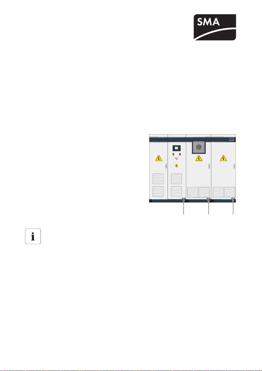
Identifying the Sunny Central
You can identify the Sunny Central by means of the type
label. The type label is located on the inside of the Sunny
Central door. The serial number is located on the front
panel of the device.
SUNNY CENTRAL 630HE
SMA
AA
Installing switch cabinet units
Sunny Centrals are supplied as two switch cabinet units. If several Sunny Centrals are
delivered and installed together, the cabinet units bearing the same serial number must be
installed side by side.
Installation Guide 1/2 Errata_SC-IEN091911
A
Page 2
SMA Solar Technology AG
Analog inputs
The remarks on analog inputs apply to Sunny Central devices with a Sunny Central Control 03 from
firmware version 1.06.
Analog Sensors and external Signal
In the Sunny Central it is possible to install a temperature sensor PT 100 and 2 additional sensors
(preconfigured as ExtSollrr, ExtGlolrr) on the Sunny Central Control panel via the customer's terminal
strip. See the table below for the respective customer-supplied connection possibilities. These sensors
can be configured by the customer.
In addition to the analog sensors one further signal (ExtAlarm) can be installed. This signal has a
direct impact on the operation of the Sunny Central.
In order to connect the signal ExtAlarm a 230 V
Connecting the Sensors
Procedure for connecting the sensors to the terminal strip in the Sunny Central Control
panel is described in the accompanying documentation.
Configuring the Sensors
Please refer to the Sunny Central user manual for detailed information.
Summary of Analog Inputs
Layout of Analog Inputs on the Sunny Central control panel
For the connection of the analog sensors and for the digital signals it is imperative to follow
the circuit diagram provided.
The connection is made at the connection terminals. Here, the connections for fourconductor and two-conductor sensors must be observed. Any required instrument
transformers should be made available.
power supply must be available.
AC
Analog inputs Ain Name Meaning
Customer Ain3 ExtSollrr External irradiation sensor
Customer Ain4 ExtGlolrr Pyranometer (measurement of global solar radiation)
Customer Ain5 ExtAlarm External alarm input, e. g. for monitoring the
functioning of the medium-voltage transformer
Customer Ain8 TmpExt C External temperature sensor / PT 100
Installation Guide 2/2 Errata_SC-IEN091911
 Loading...