

SMA S, SRC-1, AS-Box-S.1, SBU 2200 Technical Description
Backup-System
SUNNY BACKUP SYSTEM S
Technical Description
SBU2200-TEN083320 | 98-2004520 | Version 2.0
EN

Overview of the Navigation Area:
Main menu
Home Screen
100# METERS
200# SETTINGS
Submenu 1
110# Meter
120#
130#
150# Meter Compact
210# Set Inverter
220# Set
230# Set
240# Set Relay
250# Set System
260# Set Password
310# Diag
Inverter
Meter Battery
Meter Backup
Battery
Backup
Inverter
Submenu 2
112# Meter Device
132# State Grid
134# Meter Device
221# Bat Property
222# Bat Chargemode
223# Bat Protection
224# Bat Silentmode
231# Backup General
232# Grid Control
235# Installer Code
241# Relay General
242# Relay Load
243# Relay Timer
311# Diag Total
312# Diag Device
300# DIAGNOSIS
400# FAILURE/EVENT
500# OPERATION
600# DIRECT ACCESS
320# Diag Battery
330#
Diag Backup
410# Fail Current
420# Fail History
430# Event History
510# Oper
520#
530#
550# Oper SD Card
Inverter
Oper Battery
Oper Backup
331# Diag Grid

SMA Solar Technology AG Table of Contents
Table of Contents
1 Notes on this Manual. . . . . . . . . . . . . . . . . . . . . . . . . . . . . . 9
1.1 Validity . . . . . . . . . . . . . . . . . . . . . . . . . . . . . . . . . . . . . . . . . . . . 9
1.2 Storage of this Manual . . . . . . . . . . . . . . . . . . . . . . . . . . . . . . . . 9
1.3 Symbols Used . . . . . . . . . . . . . . . . . . . . . . . . . . . . . . . . . . . . . . 10
1.4 Syntaxes . . . . . . . . . . . . . . . . . . . . . . . . . . . . . . . . . . . . . . . . . . 10
2 The Sunny Backup System S . . . . . . . . . . . . . . . . . . . . . . . 11
2.1 Properties . . . . . . . . . . . . . . . . . . . . . . . . . . . . . . . . . . . . . . . . . 11
2.2 System constellation . . . . . . . . . . . . . . . . . . . . . . . . . . . . . . . . . 13
3 Safety Instructions . . . . . . . . . . . . . . . . . . . . . . . . . . . . . . . 14
4 Unpacking. . . . . . . . . . . . . . . . . . . . . . . . . . . . . . . . . . . . . . 15
4.1 Packing List . . . . . . . . . . . . . . . . . . . . . . . . . . . . . . . . . . . . . . . . 16
4.1.1 Sunny Backup 2200 . . . . . . . . . . . . . . . . . . . . . . . . . . . . . . . . . . . . . . . . . . . 16
4.1.2 Automatic Switch Box S . . . . . . . . . . . . . . . . . . . . . . . . . . . . . . . . . . . . . . . . 17
4.1.3 Sunny Remote Control 1 . . . . . . . . . . . . . . . . . . . . . . . . . . . . . . . . . . . . . . . . 18
4.1.4 BatFuse A.01 . . . . . . . . . . . . . . . . . . . . . . . . . . . . . . . . . . . . . . . . . . . . . . . . 19
4.2 Required Tools and Resources . . . . . . . . . . . . . . . . . . . . . . . . . 20
4.3 Type Label/Firmware Version. . . . . . . . . . . . . . . . . . . . . . . . . . 21
4.3.1 Sunny Backup 2200 . . . . . . . . . . . . . . . . . . . . . . . . . . . . . . . . . . . . . . . . . . . 21
4.3.2 Automatic Switch Box S . . . . . . . . . . . . . . . . . . . . . . . . . . . . . . . . . . . . . . . . 22
4.3.3 Sunny Remote Control 1 . . . . . . . . . . . . . . . . . . . . . . . . . . . . . . . . . . . . . . . . 23
4.3.4 BatFuse A.01 . . . . . . . . . . . . . . . . . . . . . . . . . . . . . . . . . . . . . . . . . . . . . . . . 24
5 Mounting. . . . . . . . . . . . . . . . . . . . . . . . . . . . . . . . . . . . . . . 25
5.1 Sunny Backup 2200. . . . . . . . . . . . . . . . . . . . . . . . . . . . . . . . . 25
5.1.1 Dimensions . . . . . . . . . . . . . . . . . . . . . . . . . . . . . . . . . . . . . . . . . . . . . . . . . . 25
5.1.2 Selecting the Mounting Location. . . . . . . . . . . . . . . . . . . . . . . . . . . . . . . . . . 26
5.1.3 Observe Minimum Clearances . . . . . . . . . . . . . . . . . . . . . . . . . . . . . . . . . . . 27
5.1.4 Mounting Position . . . . . . . . . . . . . . . . . . . . . . . . . . . . . . . . . . . . . . . . . . . . . 28
Technical Description SBU2200-TEN083320 3

Table of Contents SMA Solar Technology AG
5.1.5 Mounting the Sunny Backup 2200 using the wall mounting bracket . . . . . . 29
5.2 Automatic Switch Box S . . . . . . . . . . . . . . . . . . . . . . . . . . . . . . 33
5.2.1 Dimensions . . . . . . . . . . . . . . . . . . . . . . . . . . . . . . . . . . . . . . . . . . . . . . . . . . 33
5.2.2 Selecting the Mounting Location. . . . . . . . . . . . . . . . . . . . . . . . . . . . . . . . . . 34
5.2.3 Wall Mounting . . . . . . . . . . . . . . . . . . . . . . . . . . . . . . . . . . . . . . . . . . . . . . . 34
5.3 Sunny Remote Control 1. . . . . . . . . . . . . . . . . . . . . . . . . . . . . . 35
5.3.1 Dimensions . . . . . . . . . . . . . . . . . . . . . . . . . . . . . . . . . . . . . . . . . . . . . . . . . . 35
5.3.2 Selecting the Mounting Location. . . . . . . . . . . . . . . . . . . . . . . . . . . . . . . . . . 35
5.3.3 Wall Mounting . . . . . . . . . . . . . . . . . . . . . . . . . . . . . . . . . . . . . . . . . . . . . . . 36
5.4 BatFuse A.01 . . . . . . . . . . . . . . . . . . . . . . . . . . . . . . . . . . . . . . 37
5.4.1 Dimensions . . . . . . . . . . . . . . . . . . . . . . . . . . . . . . . . . . . . . . . . . . . . . . . . . . 37
5.4.2 Observe Minimum Clearances . . . . . . . . . . . . . . . . . . . . . . . . . . . . . . . . . . . 37
5.4.3 Wall Mounting . . . . . . . . . . . . . . . . . . . . . . . . . . . . . . . . . . . . . . . . . . . . . . . 38
5.5 Installing Batteries . . . . . . . . . . . . . . . . . . . . . . . . . . . . . . . . . . . 40
6 Opening and Closing. . . . . . . . . . . . . . . . . . . . . . . . . . . . . 43
6.1 Sunny Backup 2200. . . . . . . . . . . . . . . . . . . . . . . . . . . . . . . . . 43
6.2 Automatic Switch Box S . . . . . . . . . . . . . . . . . . . . . . . . . . . . . . 44
6.3 BatFuse A.01 . . . . . . . . . . . . . . . . . . . . . . . . . . . . . . . . . . . . . . 45
7 Electrical Connection of the Sunny Backup 2200 . . . . . . 46
7.1 At a Glance . . . . . . . . . . . . . . . . . . . . . . . . . . . . . . . . . . . . . . . 47
7.2 DC Connection . . . . . . . . . . . . . . . . . . . . . . . . . . . . . . . . . . . . . 50
7.2.1 Grounding. . . . . . . . . . . . . . . . . . . . . . . . . . . . . . . . . . . . . . . . . . . . . . . . . . . 50
7.2.2 BatFuse A.01 (DC fuse) . . . . . . . . . . . . . . . . . . . . . . . . . . . . . . . . . . . . . . . . 51
7.2.3 Connecting the Battery . . . . . . . . . . . . . . . . . . . . . . . . . . . . . . . . . . . . . . . . . 53
7.2.4 Connecting the Sunny Backup 2200 . . . . . . . . . . . . . . . . . . . . . . . . . . . . . . 54
7.3 AC Connection . . . . . . . . . . . . . . . . . . . . . . . . . . . . . . . . . . . . . 55
7.3.1 Grounding. . . . . . . . . . . . . . . . . . . . . . . . . . . . . . . . . . . . . . . . . . . . . . . . . . . 56
7.3.2 AC1 (AS-Box-S.1) . . . . . . . . . . . . . . . . . . . . . . . . . . . . . . . . . . . . . . . . . . . . . 57
7.3.3 AC2 (Load Meter) . . . . . . . . . . . . . . . . . . . . . . . . . . . . . . . . . . . . . . . . . . . . 59
7.4 Sunny Remote Control 1. . . . . . . . . . . . . . . . . . . . . . . . . . . . . . 60
4 SBU2200-TEN083320 Technical Description

SMA Solar Technology AG Table of Contents
7.5 Communication. . . . . . . . . . . . . . . . . . . . . . . . . . . . . . . . . . . . . 61
7.5.1 SBU 2200 and Automatic Switch Box S. . . . . . . . . . . . . . . . . . . . . . . . . . . . 61
7.5.2 SBU 2200 and an External Communication Device. . . . . . . . . . . . . . . . . . . 62
7.6 Additional Connections. . . . . . . . . . . . . . . . . . . . . . . . . . . . . . . 64
7.6.1 Battery Temperature Sensor . . . . . . . . . . . . . . . . . . . . . . . . . . . . . . . . . . . . . 64
7.6.2 Multi-function Relay 1 and 2. . . . . . . . . . . . . . . . . . . . . . . . . . . . . . . . . . . . . 65
7.6.3 BatVtgOut Power Supply . . . . . . . . . . . . . . . . . . . . . . . . . . . . . . . . . . . . . . . 67
7.6.4 Digital Input, DigIn . . . . . . . . . . . . . . . . . . . . . . . . . . . . . . . . . . . . . . . . . . . . 67
8 Electrical Connection of the Automatic Switch Box S . . . 69
8.1 At a Glance . . . . . . . . . . . . . . . . . . . . . . . . . . . . . . . . . . . . . . . 69
8.2 AC Connection . . . . . . . . . . . . . . . . . . . . . . . . . . . . . . . . . . . . . 71
8.2.1 PV Feed-In Counter (X1/PV Meter). . . . . . . . . . . . . . . . . . . . . . . . . . . . . . . . 73
8.2.2 PV System (X2/PV System) . . . . . . . . . . . . . . . . . . . . . . . . . . . . . . . . . . . . . . 75
8.2.3 Sunny Backup 2200 (X3/Sunny Backup) . . . . . . . . . . . . . . . . . . . . . . . . . . 76
8.2.4 Consumer System (X4/Backup Loads) . . . . . . . . . . . . . . . . . . . . . . . . . . . . . 77
8.3 Communication. . . . . . . . . . . . . . . . . . . . . . . . . . . . . . . . . . . . . 79
9 Control Elements . . . . . . . . . . . . . . . . . . . . . . . . . . . . . . . . 82
9.1 Display of the Sunny Backup 2200 . . . . . . . . . . . . . . . . . . . . . 82
9.2 Sunny Remote Control 1. . . . . . . . . . . . . . . . . . . . . . . . . . . . . . 84
10 (First) Commissioning. . . . . . . . . . . . . . . . . . . . . . . . . . . . . 86
10.1 Requirements. . . . . . . . . . . . . . . . . . . . . . . . . . . . . . . . . . . . . . . 86
10.2 Starting the Quick Configuration Guide (QCG). . . . . . . . . . . . 87
11 Activating and Deactivating the Backup System. . . . . . . 91
11.1 Activation / Startup. . . . . . . . . . . . . . . . . . . . . . . . . . . . . . . . . . 91
11.2 Stopping . . . . . . . . . . . . . . . . . . . . . . . . . . . . . . . . . . . . . . . . . . 93
11.3 Deactivation . . . . . . . . . . . . . . . . . . . . . . . . . . . . . . . . . . . . . . . 95
11.4 Disconnecting the Device from Voltage Sources . . . . . . . . . . . 95
11.5 Reactivating the Device Following Automatic Shutdown . . . . . 96
Technical Description SBU2200-TEN083320 5

Table of Contents SMA Solar Technology AG
12 Using the Sunny Backup 2200 . . . . . . . . . . . . . . . . . . . . . 97
12.1 Navigation Area. . . . . . . . . . . . . . . . . . . . . . . . . . . . . . . . . . . . 97
12.1.1 Home Screen . . . . . . . . . . . . . . . . . . . . . . . . . . . . . . . . . . . . . . . . . . . . . . . 100
12.1.2 Selecting a Menu . . . . . . . . . . . . . . . . . . . . . . . . . . . . . . . . . . . . . . . . . . . . 102
12.1.3 Selecting Parameters. . . . . . . . . . . . . . . . . . . . . . . . . . . . . . . . . . . . . . . . . . 103
12.1.4 Selecting Events. . . . . . . . . . . . . . . . . . . . . . . . . . . . . . . . . . . . . . . . . . . . . . 104
12.1.5 Selecting Warnings and Errors . . . . . . . . . . . . . . . . . . . . . . . . . . . . . . . . . . 104
12.2 Adjusting Settings . . . . . . . . . . . . . . . . . . . . . . . . . . . . . . . . . . 105
12.2.1 Setting Parameters . . . . . . . . . . . . . . . . . . . . . . . . . . . . . . . . . . . . . . . . . . . 105
12.2.2 Setting the Installer Password . . . . . . . . . . . . . . . . . . . . . . . . . . . . . . . . . . . 106
12.2.3 Setting the Installer Identification. . . . . . . . . . . . . . . . . . . . . . . . . . . . . . . . . 108
12.2.4 Directly Accessing the Parameters . . . . . . . . . . . . . . . . . . . . . . . . . . . . . . . 110
12.2.5 Meter Compact. . . . . . . . . . . . . . . . . . . . . . . . . . . . . . . . . . . . . . . . . . . . . . 110
13 Storing Data on an MMC/SD Card . . . . . . . . . . . . . . . . 112
13.1 Inserting the Card . . . . . . . . . . . . . . . . . . . . . . . . . . . . . . . . . . 114
13.2 Removing the Card . . . . . . . . . . . . . . . . . . . . . . . . . . . . . . . . . 115
13.3 Saving and Loading Parameters . . . . . . . . . . . . . . . . . . . . . . . 115
13.4 Writing Log Data . . . . . . . . . . . . . . . . . . . . . . . . . . . . . . . . . . 116
13.5 Displaying the Status. . . . . . . . . . . . . . . . . . . . . . . . . . . . . . . . 116
13.6 Updating Firmware . . . . . . . . . . . . . . . . . . . . . . . . . . . . . . . . . 117
14 Inverter Operation . . . . . . . . . . . . . . . . . . . . . . . . . . . . . . 119
14.1 Overload and Short-circuit Behavior. . . . . . . . . . . . . . . . . . . . 119
14.2 Device Faults and Autostart . . . . . . . . . . . . . . . . . . . . . . . . . . 119
15 Grid . . . . . . . . . . . . . . . . . . . . . . . . . . . . . . . . . . . . . . . . . . 120
15.1 Conditions. . . . . . . . . . . . . . . . . . . . . . . . . . . . . . . . . . . . . . . . 120
15.2 Operating on the Public Grid . . . . . . . . . . . . . . . . . . . . . . . . . 121
15.3 Grid Failure. . . . . . . . . . . . . . . . . . . . . . . . . . . . . . . . . . . . . . . 121
15.4 Stand-Alone Grid Operation . . . . . . . . . . . . . . . . . . . . . . . . . 121
6 SBU2200-TEN083320 Technical Description

SMA Solar Technology AG Table of Contents
15.5 Grid Reconnection . . . . . . . . . . . . . . . . . . . . . . . . . . . . . . . . . 122
15.6 Limits and Power Adjustment. . . . . . . . . . . . . . . . . . . . . . . . . . 122
16 Battery Management. . . . . . . . . . . . . . . . . . . . . . . . . . . . 123
16.1 Battery Temperature . . . . . . . . . . . . . . . . . . . . . . . . . . . . . . . . 123
16.2 Start Options. . . . . . . . . . . . . . . . . . . . . . . . . . . . . . . . . . . . . . 124
16.3 State of Charge/SOC and SOH . . . . . . . . . . . . . . . . . . . . . . 124
16.4 Charge Control. . . . . . . . . . . . . . . . . . . . . . . . . . . . . . . . . . . . 125
16.4.1 Boost Charge . . . . . . . . . . . . . . . . . . . . . . . . . . . . . . . . . . . . . . . . . . . . . . . 127
16.4.2 Full Charge . . . . . . . . . . . . . . . . . . . . . . . . . . . . . . . . . . . . . . . . . . . . . . . . . 127
16.4.3 Equalization Charge . . . . . . . . . . . . . . . . . . . . . . . . . . . . . . . . . . . . . . . . . . 127
16.4.4 Silent Mode. . . . . . . . . . . . . . . . . . . . . . . . . . . . . . . . . . . . . . . . . . . . . . . . . 128
16.4.5 Manual Equalization Charge . . . . . . . . . . . . . . . . . . . . . . . . . . . . . . . . . . . 128
16.5 Battery Preservation Mode . . . . . . . . . . . . . . . . . . . . . . . . . . . 128
16.6 Battery Diagnostics . . . . . . . . . . . . . . . . . . . . . . . . . . . . . . . . . 130
17 Relay . . . . . . . . . . . . . . . . . . . . . . . . . . . . . . . . . . . . . . . . . 131
18 Sunny Boy. . . . . . . . . . . . . . . . . . . . . . . . . . . . . . . . . . . . . 133
18.1 Setting the Stand-alone Grid Parameters . . . . . . . . . . . . . . . . 133
18.2 Frequency Shift Power Control (FSPC) . . . . . . . . . . . . . . . . . . 135
19 Maintenance and Care . . . . . . . . . . . . . . . . . . . . . . . . . . 137
19.1 Housing. . . . . . . . . . . . . . . . . . . . . . . . . . . . . . . . . . . . . . . . . . 137
19.2 Device Display . . . . . . . . . . . . . . . . . . . . . . . . . . . . . . . . . . . . 137
19.3 Sunny Remote Control 1. . . . . . . . . . . . . . . . . . . . . . . . . . . . . 137
19.4 Function Testing. . . . . . . . . . . . . . . . . . . . . . . . . . . . . . . . . . . . 137
19.5 Battery. . . . . . . . . . . . . . . . . . . . . . . . . . . . . . . . . . . . . . . . . . . 138
19.6 Disposal . . . . . . . . . . . . . . . . . . . . . . . . . . . . . . . . . . . . . . . . . 138
Technical Description SBU2200-TEN083320 7

Table of Contents SMA Solar Technology AG
20 Parameter Lists . . . . . . . . . . . . . . . . . . . . . . . . . . . . . . . . . 139
20.1 Display Values . . . . . . . . . . . . . . . . . . . . . . . . . . . . . . . . . . . . 140
20.2 Adjustable System Parameters . . . . . . . . . . . . . . . . . . . . . . . . 142
20.3 Diagnostics . . . . . . . . . . . . . . . . . . . . . . . . . . . . . . . . . . . . . . . 148
20.4 Events, Warnings and Errors (History) . . . . . . . . . . . . . . . . . . 150
20.5 Functions in Operation . . . . . . . . . . . . . . . . . . . . . . . . . . . . . . 150
21 Troubleshooting/Problem Solving . . . . . . . . . . . . . . . . . 152
21.1 Error Confirmation. . . . . . . . . . . . . . . . . . . . . . . . . . . . . . . . . . 152
21.2 Autostart Handling . . . . . . . . . . . . . . . . . . . . . . . . . . . . . . . . . 152
21.3 Handling Pending Errors During the Booting Procedure. . . . . 152
21.4 Display of Errors and Events . . . . . . . . . . . . . . . . . . . . . . . . . . 153
21.5 Events . . . . . . . . . . . . . . . . . . . . . . . . . . . . . . . . . . . . . . . . . . . 154
21.6 Error Categories . . . . . . . . . . . . . . . . . . . . . . . . . . . . . . . . . . . 155
21.7 Warnings and Error Messages. . . . . . . . . . . . . . . . . . . . . . . . 155
21.8 Troubleshooting . . . . . . . . . . . . . . . . . . . . . . . . . . . . . . . . . . . 157
22 Optional Devices . . . . . . . . . . . . . . . . . . . . . . . . . . . . . . . 162
22.1 Accessories (Optional) . . . . . . . . . . . . . . . . . . . . . . . . . . . . . . 162
22.2 SMA Products (Optional) . . . . . . . . . . . . . . . . . . . . . . . . . . . . 162
23 Technical Data . . . . . . . . . . . . . . . . . . . . . . . . . . . . . . . . . 163
23.1 Sunny Backup 2200. . . . . . . . . . . . . . . . . . . . . . . . . . . . . . . . 163
23.2 Automatic Switch Box S . . . . . . . . . . . . . . . . . . . . . . . . . . . . . 166
23.3 Sunny Remote Control 1. . . . . . . . . . . . . . . . . . . . . . . . . . . . . 167
23.4 DC fuse (BatFuse A.01) . . . . . . . . . . . . . . . . . . . . . . . . . . . . . 168
24 Contact . . . . . . . . . . . . . . . . . . . . . . . . . . . . . . . . . . . . . . . 169
25 Glossary . . . . . . . . . . . . . . . . . . . . . . . . . . . . . . . . . . . . . . 170
8 SBU2200-TEN083320 Technical Description

SMA Solar Technology AG Notes on this Manual
1 Notes on this Manual
These technical instructions address themselves to the installer as well as the operator of the Backup
System S. It explains the operating principle as well as the correct mounting, installation and operation
of a Sunny Backup System S.
Information regarding the following subjects can be found in the specified sections:
• Installation starting in section 2 „The Sunny Backup System S“ (11)
• Commissioning starting in section 9 „Control Elements“ (82)
• Functions starting in section 14 „Inverter Operation“ (119)
• Appendix starting in section 19 „Maintenance and Care“ (137)
1.1 Validity
This technical description applies to the Sunny Backup System S, which includes the Sunny Backup
2200 (SBU 2200) inverter, the Automatic Switch Box S (AS-Box-S.1) switching device, the external
Sunny Remote Control 1 (SRC-1) display as well as the external BatFuse A.01 DC fuse.
The technical description applies to the Sunny Backup 2200 with the firmware version 1.0 and higher.
You can read the the firmware version of your Sunny Backup 2200 on the display using the
"312.02 FwVer" parameter (see section 20.3 „Diagnostics“ (148)).
The Sunny Backup System S devices may only be operated in the intended area of application
provided in this documentation.
• Using a Sunny Backup System S as a system to supply power to life-sustaining medical devices
is prohibited.
• The Sunny Backup 2200 has been designed for use at elevations up to 2600 m above sea
level. Please contact SMA Solar Technology AG before using the device at elevations above
2600 m.
A performance loss of 0.5 % per 100 m is to be expected starting at an elevation of 2000 m
above sea level.
Do not use the devices of the Sunny Backup System S for purposes other than those indicated in this
technical description. Use of the device for other purposes can void the warranty as well as damage
both the devices and the system.
If you req uir e fu rth er i nfo rmation, ple ase con tac t th e Su nny Island Serviceline at +49 561 95 22 399
or by e-mail: SunnyIsland.Service@SMA.de.
1.2 Storage of this Manual
Store the manuals of the Sunny Backup System S and the installed components in the immediate
vicinity of the Sunny Backup 2200 so that they are accessible at all times.
Technical Description SBU2200-TEN083320 9

Notes on this Manual SMA Solar Technology AG
1.3 Symbols Used
The following types of safety instructions are used in this document:
DANGER!
DANGER indicates a hazardous situation which, if not avoided, will result in death or
serious injury.
WARNING!
WARNING indicates a hazardous situation which, if not avoided, could result in death or
serious injury.
CAUTION!
CAUTION indicates a hazardous situation which, if not avoided, could result in minor or
moderate injury.
NOTICE!
NOTICE indicates a situation that can result in property damage if not avoided.
Information
Information provides tips that are valuable for the optimal operation of the product.
1.4 Syntaxes
The syntaxes specified here for menus and parameters apply to the entire document:
Menu: menu number, hash, and menu name (150# Grid Meters)
Parameters: menu number, dot, parameter number and parameter name (150.01 GdRmgTm)
10 SBU2200-TEN083320 Technical Description
SMA Solar Technology AG The Sunny Backup System S
2 The Sunny Backup System S
2.1 Properties
The Sunny Backup System S consists of one Sunny Backup 2200 in combination with one Automatic
Switch Box S (AS-Box-S.1), one external Sunny Remote Control 1 (SRC-1) display and one external
BatFuse A.01 DC fuse. This system is specially designed for backup applications and enables, in
compliance with all standard requirements, continued operation of a grid-connected PV system in the
event of grid failure. Thus, this system does not replace the conventional Sunny Boy (PV inverter), but
is installed additionally. In the event of grid failure, the Sunny Backup System S first ensures safe
disconnection of the loads and the PV system from the public grid, and subsequently forms a stable
stand-alone grid, into which the Sunny Boy can then feed solar energy. The maximum period of
interruption for the loads is approximately 50 ms, which for most loads is equivalent to uninterrupted
operation.
PV-system
Public grid
PVfeed-in counter
Power supply
counter
Sunny Backup System S
Automatic Switch Box S. 1
Automatic disconnection
device for PV systems
PV coupling relay
Sunny Backup 2200
BATFUSE A.01
Battery
Consumer
Sunny Remote
Control
The Sunny Backup System S is suitable for use in conjunction with the Sunny Boy PV inverters from
SMA Solar Technology AG. The Sunny Backup System S can be integrated into new PV system
installations, and can also be retrofitted onto existing PV systems.
Along with the Sunny Backup 2200 and the automatic switching device AS-Box-S.1, a battery is
necessary as a short-term storage device, for reliable operation. During grid failure, the battery has
the task of correcting the imbalance between generation and consumption. Whenever less energy is
being generated than consumed (e.g. at night), the battery is discharged. Whenever more energy is
being generated than consumed (e.g. during the day), the battery is charged.
Technical Description SBU2200-TEN083320 11

The Sunny Backup System S SMA Solar Technology AG
The intelligent battery management built into the Sunny Backup 2200 protects the battery from
overcharging and deep discharge. This ensures that the battery service life stipulated by the battery
manufacturer can be achieved.
As an external DC fuse, the BatFuse A.01 protects the battery connections of the Sunny Backup 2200.
Additionally, the BatFuse A.01 enables the DC-side disconnection of the Sunny Backup 2200.
The Sunny Backup 2200 performs the entire controlling and regulation of the system. If the system is
in grid-parallel operation, the Sunny Backup 2200 ensures standard-compliant grid monitoring and
battery-preserving charging. The Sunny Backup 2200 is extremely quick to detect any failure of the
public grid and disconnects the system from the grid. After approx. 50 ms, the loads will be already
supplied with electricity again, from the battery. After a matter of seconds, the PV system switches to
this stand-alone grid, and either powers the loads, or is used for recharging the batteries. The
efficiency during charging, regardless of whether from the grid, or from the PV system, and during
discharging, is up to 93 %. Due to the 's very high overload capability of up to 3.8 kW for 5 minutes,
and the integrated smooth startup of the Sunny Backup 2200, critical loads with very high start
currents can also be started safely. Thus, over-dimensioning of the Sunny Backup 2200 is not
necessary.
Requirement according to VDE 0126-1-1 and guidelines of other countries
The Sunny Backup System S meets all requirements of the VDE 0126-1-1 guidelines that
are required in Germany for feeding PV electricity into the grid as well as guidelines of
other countries. The switching devices for PV feeding are implemented redundantly, and
are monitored. The safety of this system has been inspected and certified by the German
Professional Association for Precision Engineering and Electrotechnology.
Information
The Sunny Backup System S is only intended for use in TN systems!
Despite the complex functions of the Sunny Backup system, it can be installed and configured with
ease. All special material required for installation is included in th e de liv ery . Additi ona l su b-d ist rib uti on
units are generally not necessary. The safety and fuse protection concept on the consumer side, and
that of the PV system, are generally not impaired by the Sunny Backup 2200, and do not need to be
adapted.
All the settings required for operation can be quickly and easily programmed in six steps using the
"Quick Configuration Guide" of the Sunny Backup 2200. The easy-to-understand menu navigation
allows quick access to all important data, even while the system is running. An MMC/SD card
provides uncomplicated system control, and thus makes any service work easier.
Saving data and events
Al way s us e th e MM C/S D car d to sav e da ta a nd ev ent s. T his is ne cessary in order for SMA
Solar Technology AG to be able to help you in the event of a fault.
12 SBU2200-TEN083320 Technical Description

SMA Solar Technology AG The Sunny Backup System S
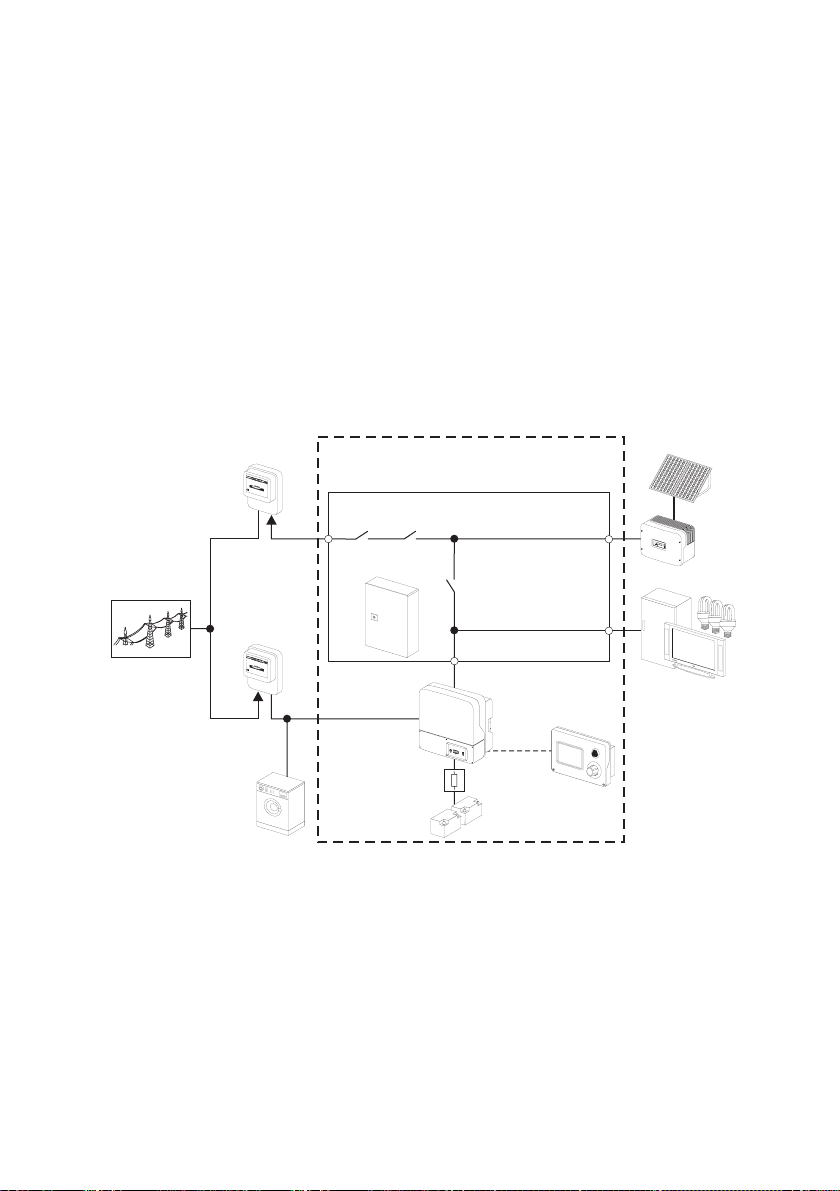
2.2 System constellation
The Sunny Backup 2200 can be integrated into different system constellations. The following graphic
illustrates the wiring of the individual components in the backup system.
PV system
Public grid
PV feed-in
counter
Equipotenti
albonding
bar
Foundation
grounding electrode
Power
supply
counter
SRC-1
PV meter
PV system
AS-Box-S.1
Backup Loads
Consumer
Sunny Backup
SBU 2200
BatFuse A.01
Battery
Technical Description SBU2200-TEN083320 13

Safety Instructions SMA Solar Technology AG
3 Safety Instructions
Please follow all operating and safety instructions in this manual. Failure to follow these instructions
could result in damage to the device or the system and cause personal injury. Store the manual at an
easily accessible location.
,
DANGER!
Risk of lethal electric shock when opening the devices.
• The devices of the backup system may only be installed and repaired by qualified
electricians.
• Observe all provisions and safety notices.
• Before working on all live components, switch them off using the line circuit breaker.
• Secure the line circuit breaker against being switched back on.
Information
Be sure to observe all applicable regional standards and guidelines.
14 SBU2200-TEN083320 Technical Description

SMA Solar Technology AG Unpacking
4 Unpacking
Before installing the Sunny Backup 2200 and the Automatic Switch Box S make sure that all parts are
included in the delivery.
• Carefully check the packaging, the Sunny Backup 2200 and the Automatic Switch Box S for
any signs of damage.
Ensure that all parts are included in the delivery (see section 4.1 „Packing List“ (16)).
If something is missing or the Sunny Backup 2200 or the Automatic Switch Box S has been damaged
during transport, contact your dealer immediately. For more information, please see section
24 „Contact“ (169).
Information
Keep the packaging in case you need to return the Sunny Backup 2200, the Automatic
Switch Box S or their accessories.
Technical Description SBU2200-TEN083320 15

Unpacking SMA Solar Technology AG
4.1 Packing List
4.1.1 Sunny Backup 2200
The following elements are included:
S
u
n
n
y
B
a
ck
u
TechnischeBeschreibung
p
S
y
s
tem
G
F
A
B
2x E
C
A 1 Sunny Backup 2200 with cover
B 1 Wall bracket
C 1 Battery temperature sensor
D 2 3-pole print terminals (for connecting relays 1 & 2)
E 2 4-pole print terminals (e.g. for connecting battery temperature sensor)
F 1 Silicone tube 10 mm x 0.5 m
G 1 Technical description (manual)
S
D
E
SBU2200-TDE080502
98-2003010
2x D
16 SBU2200-TEN083320 Technical Description

SMA Solar Technology AG Unpacking
4.1.2 Automatic Switch Box S
The following elements are included:
A
D
E
B
C
A 1 Automatic Switch Box S (AS-Box-S.1)
B 1 Socket wrench for housing cover
C 1 Set for wall mounting
• 4 x wall anchors (6 mm)
• 4 x screws
• 4 x rubber washers
D 2 CAT5e-FTP patch cables (1 x red and 1 x black with two RJ45 plugs each)
E 1 Cable ties
Technical Description SBU2200-TEN083320 17

Unpacking SMA Solar Technology AG
4.1.3 Sunny Remote Control 1
The following elements are included:
A
C
B
D
A 1 Sunny Remote Control 1 (SRC-1)
B 2 Fixing screws and wall anchors
C 1 CAT5e-FTP patch cables (2 x RJ45 plugs, 5 m)
D 1 MMC/SD card
18 SBU2200-TEN083320 Technical Description

SMA Solar Technology AG Unpacking
4.1.4 BatFuse A.01
The following elements are included:
A
B
D
C
A 1 DC fuse BatFuse A.01
B 4 Wall mounting plate
C 6 Double membrane adapter
D 2 Fuse plug 125 A NH-00
Technical Description SBU2200-TEN083320 19

Unpacking SMA Solar Technology AG
4.2 Required Tools and Resources
You require the following tools and materials in order to mount and i nstall the Sunny Backup System S:
Tools (not included in delivery)
Stripping pliers
Cable end sleeves
Drill
Drill (e.g. stone drill), from Ø 6 mm to 10 mm
Torque wrench (4 Nm to 10 Nm), socket wrench, 13 mm
Hexagon (allen) key, 4 mm
Cable knife
Combination pliers
Phillips screwdriver, PH1 and PH2
Cable
Open-end/ring wrenches, 13 mm
Multimeter
Flathead screwdriver, 0.4 x 2.5 mm/1.0 x 10 mm/1.0 x 5.5 mm
Diagonal cutting pliers
Spirit level
Ratchet
Ratchet extension
NH handle (as per VDE 0680-4)
Material (not included in delivery)
Wall anchors for the wall bracket (e.g. SX 10)
Cable ties
Heat shrink tubing
Hexagon bolts, 8 x 60 mm, washers
20 SBU2200-TEN083320 Technical Description

SMA Solar Technology AG Unpacking
4.3 Type Label/Firmware Version
4.3.1 Sunny Backup 2200
You can identify the Sunny Backup 2200 by the type label and the firmware version.
• The type label is located outside on the right side of
the housing.
• You can read the the firmware version of your
device on the display using the "312.02 FwVer"
parameter (see section 20.3 „Diagnostics“ (148)).
Technical Description SBU2200-TEN083320 21

Unpacking SMA Solar Technology AG
4.3.2 Automatic Switch Box S
You can identify the Automatic Switch Box S by the type label.
The type label is located outside on the right side of the
housing.
22 SBU2200-TEN083320 Technical Description

SMA Solar Technology AG Unpacking
4.3.3 Sunny Remote Control 1
You can identify the display from the type label. The type label is located on the rear side of the Sunny
Remote Control 1.
Technical Description SBU2200-TEN083320 23

Unpacking SMA Solar Technology AG
4.3.4 BatFuse A.01
You can identify the DC fuse by the type label.
The type label is located inside on the right side of
the housing.
24 SBU2200-TEN083320 Technical Description

SMA Solar Technology AG Mounting
5 Mounting
Take note of the required installation conditions listed below before mounting, installing and
commissioning the Sunny Backup 2200 and the Automatic Switch Box S.
Information
When selecting the mounting location, you must observe the applicable building
regulations (e. g. the German model cable/pipe system directive MLAR). During planning,
clarify the provisions for stairwells or escape routes with the respective fire protection
authority.
5.1 Sunny Backup 2200
5.1.1 Dimensions
Housing:
180 mm
445 mm
470 mm
Technical Description SBU2200-TEN083320 25
Mounting SMA Solar Technology AG
Wall bracket:
315.9 mm
260 mm
170 mm
5.1.2 Selecting the Mounting Location
DANGER!
Danger to life due to fire or explosion.
During operation, the temperature of the housing may exceed 60 °C.
Do not install the device
• on flammable construction materials,
• in areas where highly flammable materials are stored,
• in potentially explosive areas
CAUTION!
Touching could result in burns.
During operation, the temperature of the housing may exceed 60 °C.
• Mount the device such that it cannot be touched inadvertently.
26 SBU2200-TEN083320 Technical Description

SMA Solar Technology AG Mounting
• The mounting location and mounting method must be suitable for the weight (approx. 18 kg)
and dimensions.
• Select a solid surface for mounting the device.
• The mounting location must be accessible at all times (do not mount in inaccessible locations).
• An ambient temperature between –25 °C and +60 °C ensures optimum operation.
• Do not expose the device to direct sunlight. Due to overheating, power reductions may occur.
• In a living area, do not mount the unit on plasterboard
etc. walls as otherwise audible vibrations are likely to
result.
The Sunny Backup 2200 can make noises when in use
which can be seen as a nuisance when installed in a
living area.
5.1.3 Observe Minimum Clearances
Observe the following minimum clearances to walls, other devices or objects, in order to guarantee
sufficient heat dissipation.
All external cables are connected through the
underside of the housing. This requires a minimum
clearance of at least 50 cm.
Direction Minimum clearance
Sides 10 cm
Top 30 cm
Below 50 cm
Front 5 cm
Sufficient Ventilation
When installing the Sunny Backup 2200 in smaller rooms, make sure that adequate
ventilation is available. The device produces heat when operating that must be removed.
Technical Description SBU2200-TEN083320 27

Mounting SMA Solar Technology AG
5.1.4 Mounting Position
NOTICE!
Short circuit due to condensation.
Condensation water can build up if the device is operated in a horizontal position.
• Only operate the device when it is in a vertical position hanging on a wall.
• Mount the device vertically on a wall or tilted backwards at a maximum of 15°!
• Mount the device at eye level.
• Never install the device with a forward tilt!
• Do not install horizontally!
28 SBU2200-TEN083320 Technical Description

SMA Solar Technology AG Mounting
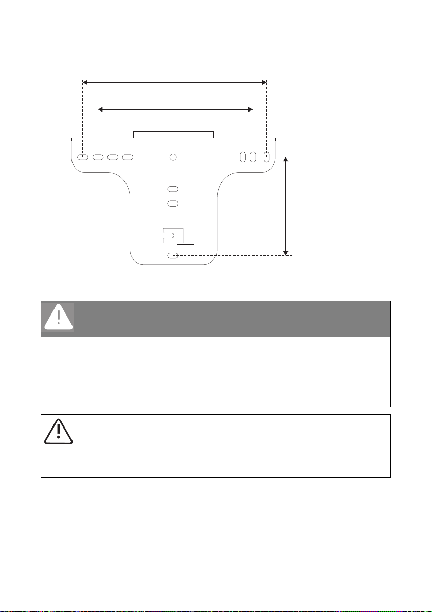
5.1.5 Mounting the Sunny Backup 2200 using the wall mounting bracket
1. Use the wall bracket as a drilling template.
Number of drill holes used
• When wall mounting the unit, use at least two of the horizontal holes and the lowest
hole in the middle.
• When mounting the device on a post, use at least three of the holes located in the
center (always use the top holes).
.
315.9 mm
260 mm
170 mm
Mounting Material
When mounting the wall bracket, use fastening material suitable for the mounting surface.
Observe the weight of the Sunny Backup 2200 (approx. 18 kg).
2. Mount the wall bracket.
Technical Description SBU2200-TEN083320 29

Mounting SMA Solar Technology AG
Transporting the Sunny Backup 2200
When transporting and mounting the
Sunny Backup 2200, use the ergonomic
handles at the sides of the housing.
3. Attach the device to the wall mounting bracket
slightly to the left using its mounting plate.
The right edge of the rear wall of the device
must be flush with the right edge of the wall
bracket.
4. Check both sides to ensure that it is correctly in
place.
30 SBU2200-TEN083320 Technical Description
 Loading...