

SMA SBS3.7-10, SBS6.0-10, SBS5.0-10 Service Manual
SBSxx-10-AT-PU-SG-xx-10 | 112919-00.01 | Version 1.0
SBS3.7-10 / SBS5.0-10 / SBS6.0-10
Replacing the Power Unit

SBSxx-10-AT-PU-SG-xx-102
ENGLISH Service Manual .........................................................................3
DEUTSCH Serviceanleitung......................................................................17
ESPAÑOL Instrucciones de servicio técnico............................................31
FRANÇAIS Manuel de service...................................................................45
ITALIANO Manuale di servizio ................................................................59

Table of Contents
SMA Solar Technology AG
Service Manual SBSxx-10-AT-PU-SG-xx-10 3
Table of Contents
1 Information on this Document................................................. 4
1.1 Validity........................................................................................................................ 4
1.2 Target Group.............................................................................................................. 4
1.3 Structure...................................................................................................................... 4
1.4 Levels of warning messages...................................................................................... 4
1.5 Symbols in the Document .......................................................................................... 5
1.6 Typographies in the document.................................................................................. 5
1.7 Designation in the document..................................................................................... 5
2 Safety Information ................................................................... 5
3 Overview of the Enclosure Parts............................................. 8
4 Checking the Firmware Version.............................................. 8
5 Disassembling the Defective Power Unit................................ 9
6 Mounting the New Power Unit ............................................... 11
7 Packaging the Defective Power Unit for Pick-Up .................. 14
8 Contact ...................................................................................... 14
ENGLISH
1 Information on this Document
SMA Solar Technology AG
Service ManualSBSxx-10-AT-PU-SG-xx-104
1 Information on this Document
1.1 Validity
This document is valid for:
• SBS3.7-10 (SunnyBoyStorage 3.7)
• SBS5.0-10 (SunnyBoyStorage 5.0)
• SBS6.0-10 (SunnyBoyStorage 6.0)
1.2 Target Group
The tasks described in this document must only be performed by qualified persons. Qualified
persons must have the following skills:
• Knowledge of how to safely disconnect SMA inverters
• Knowledge of how batteries work and are operated
• Training in how to deal with the dangers and risks associated with installing, repairing and
using electrical devices, batteries and installations
• Training in the installation and commissioning of electrical devices and installations
• Knowledge of all applicable laws, standards and directives
• Knowledge of and compliance with this document and all safety information
• Knowledge of and compliance with the documents of the battery manufacturer with all safety
information
1.3 Structure
This document describes how to replace defective components. This document supplements the
documents that are enclosed with each product and does not replace any locally applicable
standards or directives. Read and observe all documents supplied with the product.
You can find a detailed manual of the product in PDF format at www.SMA-Solar.com.
1.4 Levels of warning messages
The following levels of warning messages may occur when handling the product.
DANGER
Indicates a hazardous situation which, if not avoided, will result in death or serious injury.
WARNING
Indicates a hazardous situation which, if not avoided, could result in death or serious injury.
CAUTION
Indicates a hazardous situation which, if not avoided, could result in minor or moderate injury.
ENGLISH

2 Safety Information
SMA Solar Technology AG
Service Manual SBSxx-10-AT-PU-SG-xx-10 5
NOTICE
Indicates a situation which, if not avoided, can result in property damage.
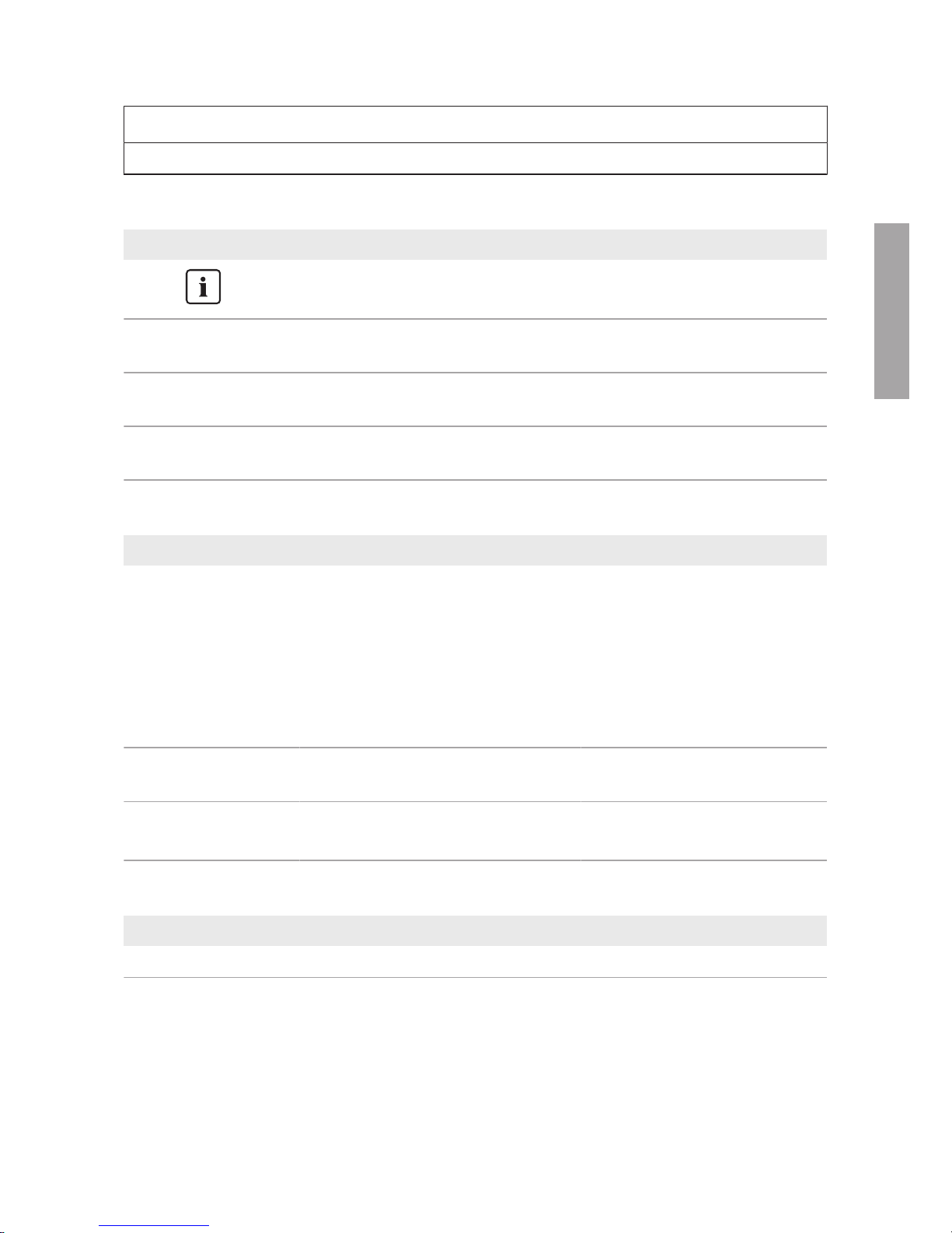
1.5 Symbols in the Document
Symbol Explanation
Information that is important for a specific topic or goal, but is not
safety-relevant
☐
Indicates a requirement for meeting a specific goal
☑
Desired result
✖
A problem that might occur
1.6 Typographies in the document
Typography Use Example
bold
• Messages
• Terminals
• Elements on a user interface
• Elements to be selected
• Elements to be entered
• Connect the insulated
conductors to the terminals
X703:1 to X703:6.
• Enter 10 in the field
Minutes.
>
• Connects several elements to be
selected
• Select Settings > Date.
[Button]
[Key]
• Button or key to be selected or
pressed
• Select [Enter].
1.7 Designation in the document
Complete designation Designation in this document
SunnyBoyStorage Inverter, product
2 Safety Information
This section contains safety information that must be observed at all times when working on or with
the product.
To prevent personal injury and property damage and to ensure long-term operation of the product,
read this section carefully and observe all safety information at all times.
ENGLISH
2 Safety Information
SMA Solar Technology AG
Service ManualSBSxx-10-AT-PU-SG-xx-106
DANGER
Danger to life from electric shock due to live DC cables at the battery.
The DC cables connected to a battery may be live. Touching the DC conductors or the live
components leads to lethal electric shocks.
• Do not touch non-insulated cable ends.
• Do not touch any live components.
• Have the inverter and the battery mounted, installed and commissioned only by qualified
persons with the appropriate skills.
• Observe all safety information of the battery manufacturer.
• Prior to performing any work on the inverter or the battery, disconnect the inverter from all
voltage sources as described in this document.
• Wait five minutes before working on the inverter.
• If an error occurs, have it rectified by qualified persons only.
WARNING
Risk of burns due to electric arcs
Short-circuit currents in the battery can cause heat build-up and electric arcs.
• Disconnect the battery from all voltages sources prior to performing any work on the
battery.
• Observe safety information of the battery manufacturer when working on the battery or
inverter.
CAUTION
Risk of burns from hot surfaces
The surface of the inverter can get very hot. Touching the surface can result in burns.
• Mount the inverter in such a way that it cannot be touched inadvertently.
• Do not touch hot surfaces.
• Wait 30 minutes for the surface to cool sufficiently.
• Observe the safety messages on the inverter.
ENGLISH
2 Safety Information
SMA Solar Technology AG
Service Manual SBSxx-10-AT-PU-SG-xx-10 7
NOTICE
Damage to the enclosure seal in subfreezing conditions
If you open the product when temperatures are below freezing, the enclosure seals can be
damaged. Moisture can penetrate the product then.
• Only open the product if the ambient temperature is not below 0°C.
• If a layer of ice has formed on the enclosure seal when temperatures are below freezing,
remove it prior to opening the product (e.g. by melting the ice with warm air). Observe the
applicable safety regulations.
• Do not disassemble the PowerUnit unless the ambient temperature is at least 0°C (32°F)
and conditions are frost-free.
NOTICE
Damage due to sand, dust and moisture ingress
Sand, dust and moisture penetration can damage the product and impair its functionality.
• Only open the product if the humidity is within the thresholds and the environment is free of
sand and dust.
• Do not open the product during a dust storm or precipitation.
• Only disassemble the PowerUnit if a new PowerUnit is already available.
NOTICE
Damage due to cleaning agents
The use of cleaning agents may cause damage to the product and its components.
• Clean the product and all its components only with a cloth moistened with clear water.
NOTICE
Damage to the inverter due to electrostatic discharge
Touching electronic components can cause damage to or destroy the inverter through
electrostatic discharge.
• Ground yourself before touching any component.
ENGLISH
3 Overview of the Enclosure Parts
SMA Solar Technology AG
Service ManualSBSxx-10-AT-PU-SG-xx-108
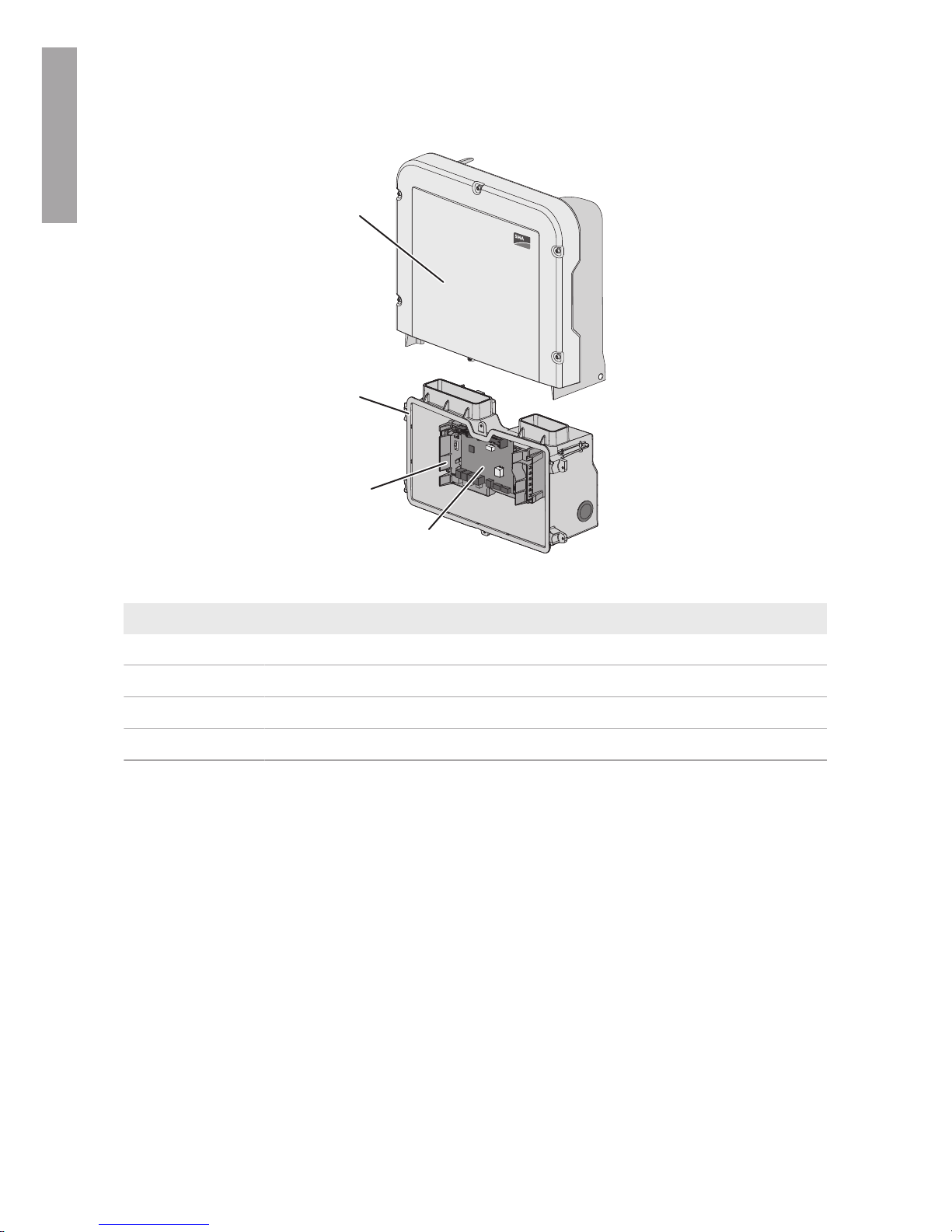
3 Overview of the Enclosure Parts
A
C
B
D
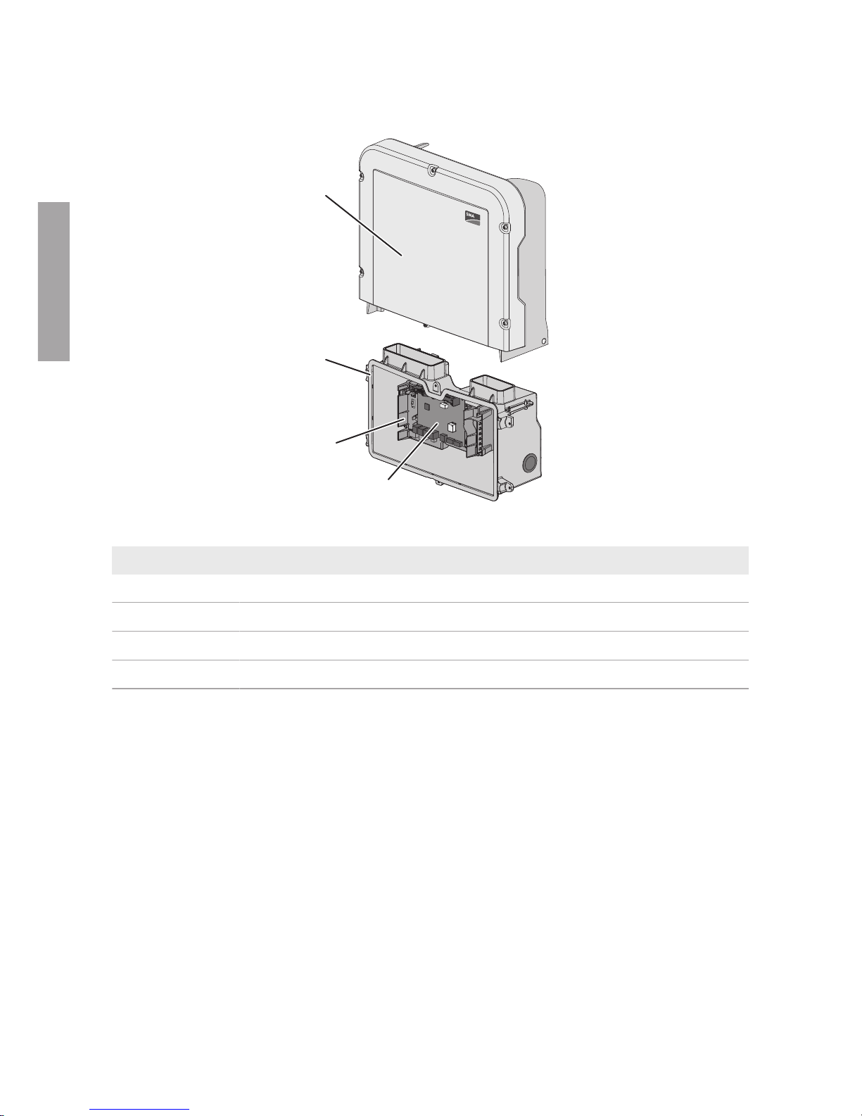
Figure 1 : Overview of the enclosure parts
Position Designation
A Power Unit
B Connection Unit
C Communication assembly
D Interface module of the battery
4 Checking the Firmware Version
1. Activate the user interface of the inverter (see the inverter manual).
2. Log into the user interface as an Installer.
3. Select the menu Device Configuration.
4. Check the installed firmware version. The firmware version must be up to date.
5. Update the firmware to the latest version if it is not up to date. To do this, download the current
update package at www.SMA-Solar.com and select the menu Settings > Perform firmware
update in the overview on the user interface, and load the saved update package and select
[Perform firmware update].
☑ The firmware version is being updated.
6. If the firmware version could not be updated, replace the PowerUnit without the current
firmware version.
ENGLISH
5 Disassembling the Defective Power Unit
SMA Solar Technology AG
Service Manual SBSxx-10-AT-PU-SG-xx-10 9
5 Disassembling the Defective Power Unit
Prior to disassembling the defective Power Unit, all connections between the Power Unit and the
Connection Unit must be severed. Only then can the Power Unit be removed from the Connection
Unit. All cables connected to the communication assembly can remain plugged in and do not need
to be removed to disassemble the PowerUnit.
Procedure:
1.
DANGER
Danger to life due to high voltages
• Disconnect the inverter from voltage sources (see inverter manual).
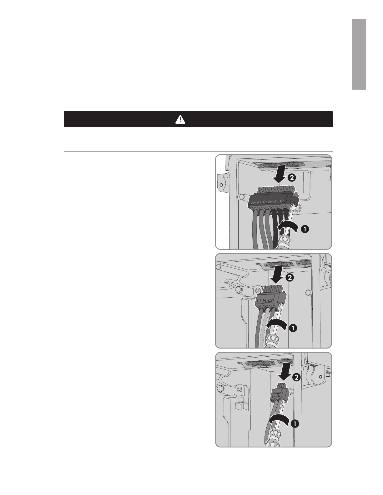
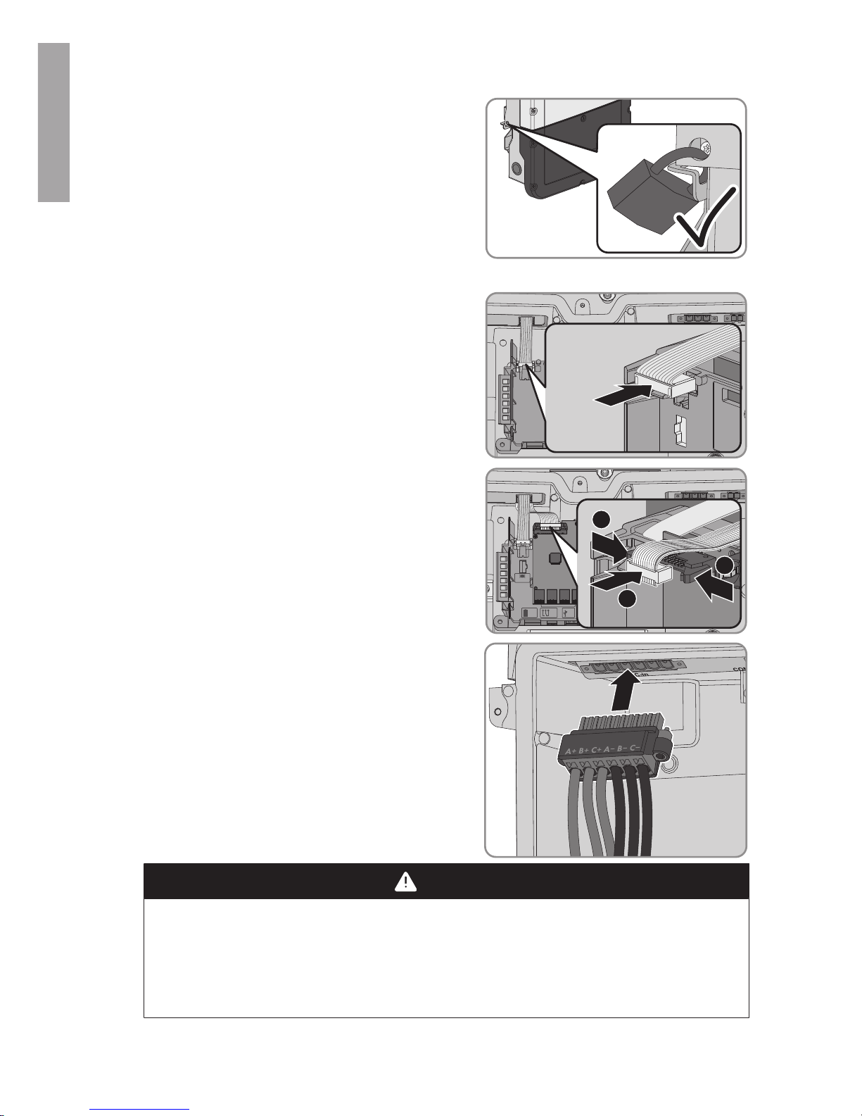
2. Remove the terminal block with the connected DC
conductors from slot DC-in. To do this, unscrew the
screws using a flat-blade screwdriver (blade width:
4mm (5⁄32in)) and pull the terminal block out of
the slot. While doing so, only touch the terminal
block on the black enclosure.
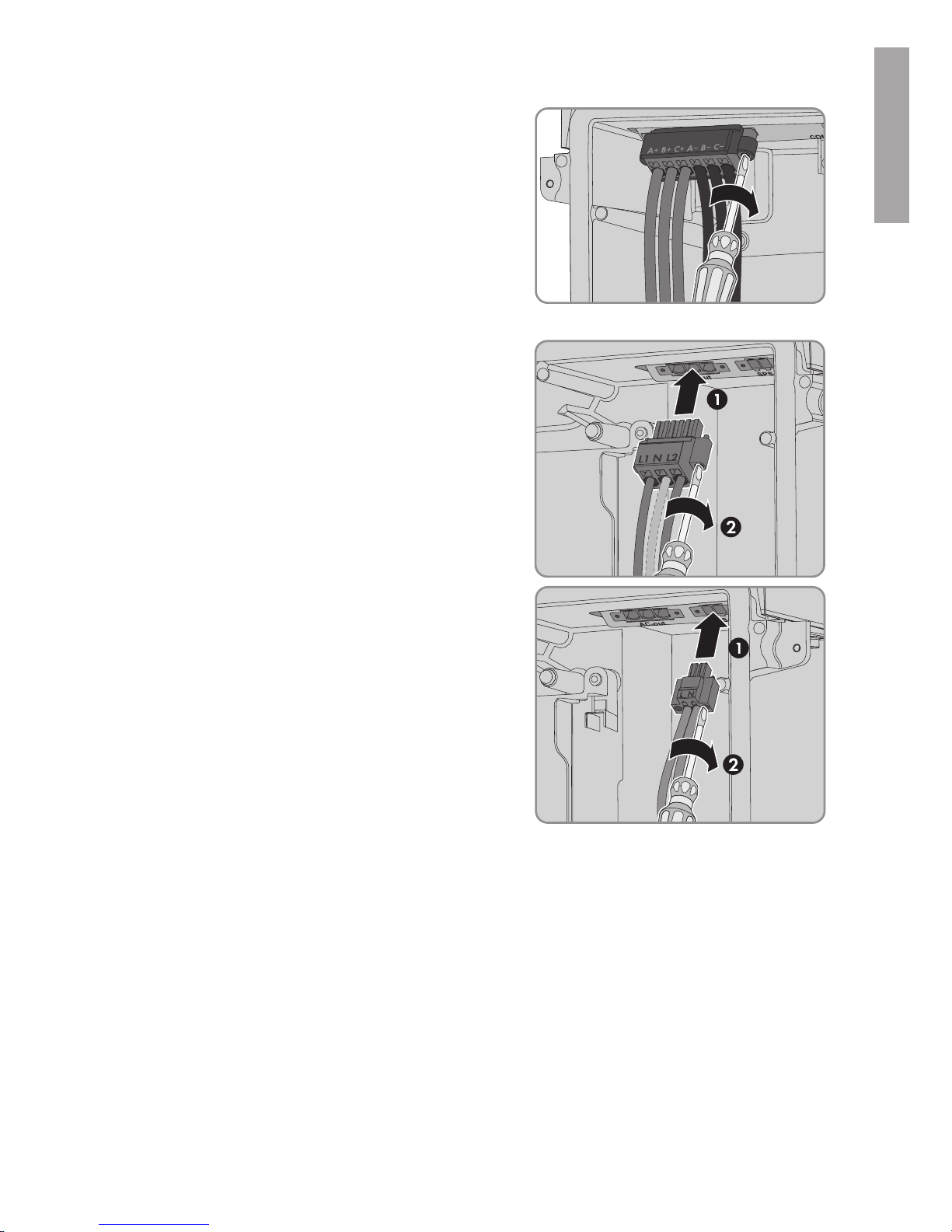
3. Remove the terminal block with the connected AC
conductors from slot AC-out. To do this, unscrew the
screws using a flat-blade screwdriver (blade width:
4mm (5⁄32in)) and pull the terminal block out of
the slot.
4. If there is a switch and an outlet for secure power
supply operation connected, remove the terminal
block with the connected cable from the SPS slot. To
do this, unscrew the screws using a flat-blade
screwdriver (blade width: 3.5mm) and pull the
terminal block out of the slot.
ENGLISH
5 Disassembling the Defective Power Unit
SMA Solar Technology AG
Service ManualSBSxx-10-AT-PU-SG-xx-1010
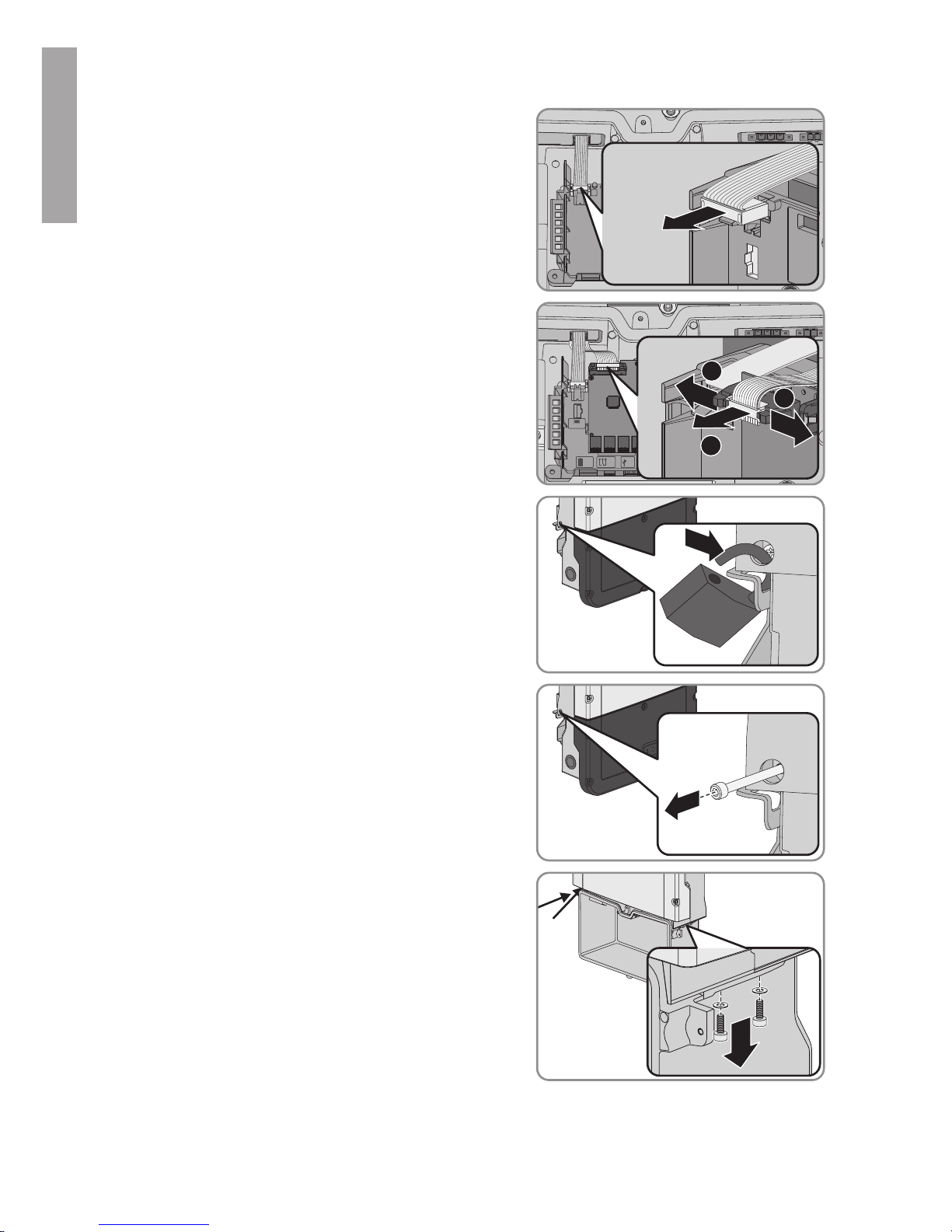
5. Pull the ribbon cable connecting the communication
assembly to the PowerUnit out of the
communication assembly.
COM
SPS
AC-out
D-IN
SPS
A B
M1
X1 X2
M2
ANT.
FCC ID: SVF-KP20
IC: 9440A-KP20
6. Pull the ribbon cable connecting the communication
assembly to the battery interface module out of the
battery interface module.
COM
SPS
AC-out
D-IN
SPS
A B
M1
X1 X2
M2
ANT.
FCC ID: SVF-KP20
IC: 9440A-KP20
Max. 30V DC
DISPLAY
BAT MFR
USB
+
_
1
1
2
7. If the inverter is fitted with a padlock for theft
protection, open the padlock and remove it.
8. Using a Torx screwdriver (TX 25), unscrew the
screw M5x60 which fastens the inverter to the wall
mounting bracket.
9. Unscrew the two screws on the right and left side of
the PowerUnit with a Torx screwdriver (TX25) and
retain together with the washers for later use.
ENGLISH
6 Mounting the New Power Unit
SMA Solar Technology AG
Service Manual SBSxx-10-AT-PU-SG-xx-10 11
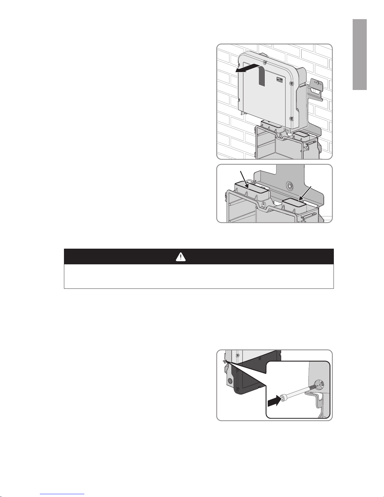
10. Lift to remove the Power Unit out of the wall
mounting bracket, thus separating the Power Unit
from the Connection Unit.
T
OP
11. If necessary, remove residual insulation material
from the two connection openings at the top of the
Connection Unit.
6 Mounting the New Power Unit
1.
DANGER
Danger to life due to high voltages
• Disconnect the inverter from voltage sources (see inverter manual).
2. Hook the new Power Unit into the upper recesses of the wall mounting bracket, thus plugging
the Power Unit into the Connection Unit. Make sure that the screw holes on the left and right
sides of the PowerUnit are directly over those of the ConnectionUnit; and the cables
protruding from the PowerUnit must not be pinched.
3. Fasten two screws with washers on the right and left side of the PowerUnit using a Torx
screwdriver (TX25) (torque: 6Nm ± 0.3Nm).
4. Secure the inverter to the wall mounting bracket. To
do this, insert the screw M5x60 through the hole on
the left side of the PowerUnit using a Torx
screwdriver (TX25) and screw it into the thread
(torque: 1.7Nm ± 0.3Nm).
5. If the inverter is to be protected against theft, attach a padlock:
ENGLISH
6 Mounting the New Power Unit
SMA Solar Technology AG
Service ManualSBSxx-10-AT-PU-SG-xx-1012
• To do this, guide the shackle of the padlock
through the provided hole on the left side of the
Power Unit and close the shackle.
• Keep the key of the padlock in a safe place.
6. Pull the ribbon cable used to connect the
communication assembly to the PowerUnit into the
ConnectionUnit, and plug it into the jack on the
communication assembly.
COM
SPS
AC-out
D-IN
SPS
A B
M1
X1 X2
M2
ANT.
FCC ID: SVF-KP20
IC: 9440A-KP20
7. Insert the ribbon cable used to connect the
communication assembly to the battery interface
module into the jack on the battery interface module
and lock it.
COM
SPS
AC-out
D-IN
SPS
A B
M1
X1 X2
M2
ANT.
FCC ID: SVF-KP20
IC: 9440A-KP20
Max. 30V DC
DISPLAY
BAT MFR
USB
+
_
1
2
2
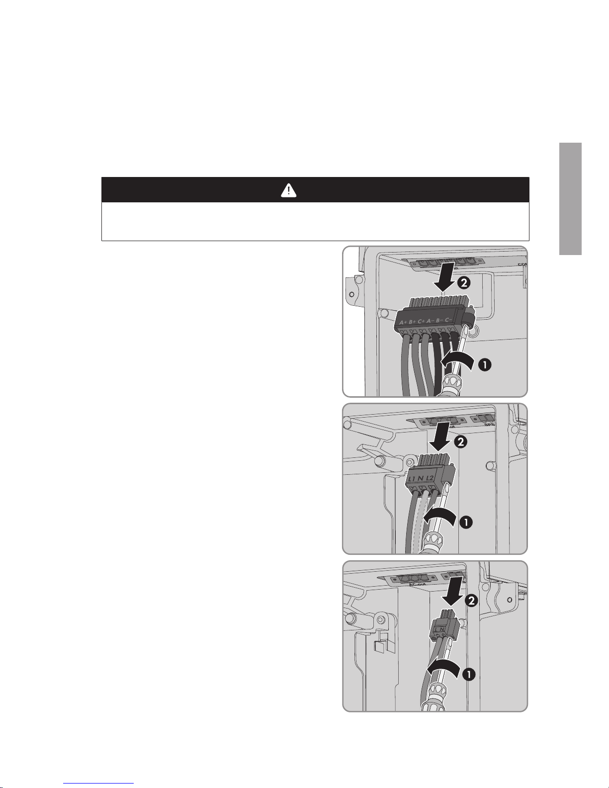
8. Plug the terminal block with the connected DC
conductors into slot DC-in in the Connection Unit.
While doing so, only touch the terminal block on the
black enclosure.
9.
DANGER
Danger to life due to electric arc
The terminal block must be fastened to the slot with two screws. If the terminal block is not
correctly mounted and comes out of the slot, an electric arc can form. An electric arc can
cause life-threatening injuries.
• Mount the terminal block on the slot as described in the following.
ENGLISH
6 Mounting the New Power Unit
SMA Solar Technology AG
Service Manual SBSxx-10-AT-PU-SG-xx-10 13
10. Tighten (torque: 1.7Nm ± 0.3Nm) the screws of
the terminal block using a flat-blade screwdriver
(blade width: 3.5mm).
11. Ensure that the terminal block is securely in place.
12. Plug the terminal block with the connected AC
conductors into the AC-out slot in the
ConnectionUnit, and tighten (torque: 1.7Nm ±
0.3Nm) with a flat-blade screwdriver (blade width:
3.5mm).
13. If applicable, plug the terminal block with the
connected cable for secure power supply operation
into the SPS slot in the Connection Unit, and tighten
(torque: 1.7Nm ± 0.3Nm) with a flat-blade
screwdriver (blade width: 3.5mm).
14. Commission the inverter (see inverter manual). The starting process of the inverter will take up
to 20 minutes since all relevant information is transferred from the ConnectionUnit to the
PowerUnit, and the PowerUnit may also be updated.
15. If the inverter firmware could not be updated prior to replacing the PowerUnit and the inverter
is not yet equipped with the current firmware version, perform a firmware update (see manual
of the inverter).
16. If a firmware update has been carried out, ensure that all parameters have been transferred
correctly and that the inverter feeds grid-compliant current into the utility grid.
ENGLISH

7 Packaging the Defective Power Unit for Pick-Up
SMA Solar Technology AG
Service ManualSBSxx-10-AT-PU-SG-xx-1014
7 Packaging the Defective Power Unit for Pick-Up
1. Package the defective Power Unit for pick-up. Use the original packaging of the new Power
Unit for this purpose.
2. Arrange for pick-up by SMA Solar Technology AG. To do this, contact Service (refer to
www.SMA-Solar.com for contact details).
8 Contact
If you have technical problems with our products, please contact the SMAServiceLine. The
following data is required in order to provide you with the necessary assistance:
• Battery inverter:
– Device type
– Serial number
– Firmware version
– Event message
– Mounting location and mounting height
– Optional equipment, e.g. communication products
– Use the name of the system in SunnyPortal (if available)
– Access data for SunnyPortal (if available)
– Special country-specific settings (if available)
• Batteries:
– Type
– Firmware version
– Type of automatic transfer switch (if available)
ENGLISH

8 Contact
SMA Solar Technology AG
Service Manual SBSxx-10-AT-PU-SG-xx-10 15
Deutschland
Österreich
Schweiz
SMA Solar Technology AG
Niestetal
Sunny Boy, Sunny Mini Central,
SunnyTripower:
+495619522‑1499
Monitoring Systems
(Kommunikationsprodukte):
+495619522‑2499
Fuel Save Controller
(PV-Diesel-Hybridsysteme):
+495619522-3199
Sunny Island, Sunny Boy Storage, Sunny Backup:
+495619522-399
Sunny Central, Sunny Central
Storage:
+495619522-299
SMA Online Service Center:
www.SMA-Service.com
Belgien
Belgique
België
Luxemburg
Luxembourg
Nederland
SMA Benelux BVBA/SPRL
Mechelen
+3215286 730
SMA Online Service Center:
www.SMA-Service.com
Česko
Magyarország
Slovensko
SMA Service Partner TERMS
a.s.
+4203876 85 111
SMA Online Service Center:
www.SMA-Service.com
Türkiye SMA Service Partner DEKOM
Ltd. Şti.
+90 24 22430605
SMA Online Service Center:
www.SMA-Service.com
France SMA France S.A.S.
Lyon
+33 472 22 97 00
SMA Online Service Center :
www.SMA-Service.com
Ελλάδα
Κύπρος
SMA Service Partner AKTOR
FM.
Αθήνα
+30 210 8184550
SMA Online Service Center:
www.SMA-Service.com
España
Portugal
SMA Ibérica Tecnología Solar,
S.L.U.
Barcelona
+34935635099
SMA Online Service Center:
www.SMA-Service.com
United Kingdom
SMA Solar UK Ltd.
Milton Keynes
+441908304899
SMA Online Service Center:
www.SMA-Service.com
Italia SMA Italia S.r.l.
Milano
+39028934-7299
SMA Online Service Center:
www.SMA-Service.com
Australia SMA Australia Pty Ltd.
Sydney
Toll free for Australia:
1800SMAAUS
(1800762287)
International:
+61294914200
ENGLISH

8 Contact
SMA Solar Technology AG
Service ManualSBSxx-10-AT-PU-SG-xx-1016
United Arab
Emirates
SMA Middle East LLC
Abu Dhabi
+9712234 6177
SMA Online Service Center:
www.SMA-Service.com
India SMA Solar India Pvt. Ltd.
Mumbai
+912261713888
ไทย SMA Solar (Thailand) Co., Ltd.
กรุงเทพฯ
+6626706999
대한민국 SMA Technology Korea Co.,
Ltd.
서울
+82-2-520-2666
South Africa SMA Solar Technology South
Africa Pty Ltd.
Cape Town
08600SUNNY (08600 78669)
International: +27 (0)21 826
0600
SMA Online Service Center:
www.SMA-Service.com
Argentina
Brasil
Chile
Perú
SMA South America SPA
Santiago de Chile
+562 2820 2101
Other countries
International SMA Service Line
Niestetal
00800SMASERVICE
(+8007627378423)
SMA Online Service Center:
www.SMA-Service.com
ENGLISH

Inhaltsverzeichnis
SMA Solar Technology AG
Serviceanleitung SBSxx-10-AT-PU-SG-xx-10 17
Inhaltsverzeichnis
1 Hinweise zu diesem Dokument............................................... 18
1.1 Gültigkeitsbereich....................................................................................................... 18
1.2 Zielgruppe .................................................................................................................. 18
1.3 Aufbau ........................................................................................................................ 18
1.4 Warnhinweisstufen..................................................................................................... 18
1.5 Symbole im Dokument............................................................................................... 19
1.6 Auszeichnungen im Dokument.................................................................................. 19
1.7 Benennungen im Dokument....................................................................................... 19
2 Sicherheitshinweise.................................................................. 19
3 Übersicht der Gehäuseteile..................................................... 22
4 Firmware-Version prüfen......................................................... 22
5 Defekte Power Unit demontieren ........................................... 23
6 Neue Power Unit montieren ................................................... 25
7 Defekte Power Unit verpacken und abholen lassen............. 28
8 Kontakt...................................................................................... 28
DEUTSCH
1 Hinweise zu diesem Dokument
SMA Solar Technology AG
ServiceanleitungSBSxx-10-AT-PU-SG-xx-1018
1 Hinweise zu diesem Dokument
1.1 Gültigkeitsbereich
Dieses Dokument gilt für:
• SBS3.7-10 (Sunny Boy Storage 3.7)
• SBS5.0-10 (Sunny Boy Storage 5.0)
• SBS6.0-10 (Sunny Boy Storage 6.0)
1.2 Zielgruppe
Die in diesem Dokument beschriebenen Tätigkeiten dürfen nur Fachkräfte durchführen. Fachkräfte
müssen über folgende Qualifikation verfügen:
• Sicherer Umgang mit dem Freischalten von SMA Wechselrichtern
• Kenntnis über Funktionsweise und Betrieb von Batterien
• Schulung im Umgang mit Gefahren und Risiken bei der Installation, Reparatur und Bedienung
elektrischer Geräte, Batterien und Anlagen
• Ausbildung für die Installation und Inbetriebnahme von elektrischen Geräten und Anlagen
• Kenntnis der einschlägigen Gesetze, Normen und Richtlinien
• Kenntnis und Beachtung dieses Dokuments mit allen Sicherheitshinweisen
• Kenntnis und Beachtung der Dokumente des Batterieherstellers mit allen Sicherheitshinweisen
1.3 Aufbau
Dieses Dokument beschreibt den Austausch von defekten Komponenten. Dieses Dokument ergänzt
die Dokumente, die jedem Produkt beigefügt sind, und ersetzt keine der vor Ort gültigen Normen
oder Richtlinien. Lesen und beachten Sie die Dokumente, die mit dem Produkt geliefert wurden.
Die ausführliche Anleitung des Produkts finden Sie im PDF-Format unter www.SMA-Solar.com.
1.4 Warnhinweisstufen
Die folgenden Warnhinweisstufen können im Umgang mit dem Produkt auftreten.
GEFAHR
Kennzeichnet einen Warnhinweis, dessen Nichtbeachtung unmittelbar zum Tod oder zu
schweren Verletzungen führt.
WARNUNG
Kennzeichnet einen Warnhinweis, dessen Nichtbeachtung zum Tod oder zu schweren
Verletzungen führen kann.
VORSICHT
Kennzeichnet einen Warnhinweis, dessen Nichtbeachtung zu leichten oder mittleren
Verletzungen führen kann.
DEUTSCH
2 Sicherheitshinweise
SMA Solar Technology AG
Serviceanleitung SBSxx-10-AT-PU-SG-xx-10 19
ACHTUNG
Kennzeichnet einen Warnhinweis, dessen Nichtbeachtung zu Sachschäden führen kann.
1.5 Symbole im Dokument
Symbol Erklärung
Information, die für ein bestimmtes Thema oder Ziel wichtig, aber
nicht sicherheitsrelevant ist
☐
Voraussetzung, die für ein bestimmtes Ziel gegeben sein muss
☑
Erwünschtes Ergebnis
✖
Möglicherweise auftretendes Problem
1.6 Auszeichnungen im Dokument
Auszeichnung Verwendung Beispiel
fett
• Meldungen
• Anschlüsse
• Elemente auf einer
Benutzeroberfläche
• Elemente, die Sie auswählen
sollen
• Elemente, die Sie eingeben sollen
• Adern an die
Anschlussklemmen X703:1
bis X703:6 anschließen.
• Im Feld Minuten den Wert
10 eingeben.
>
• Verbindet mehrere Elemente, die
Sie auswählen sollen
• Einstellungen > Datum
wählen.
[Schaltfläche]
[Taste]
• Schaltfläche oder Taste, die Sie
wählen oder drücken sollen
• [Enter] wählen.
1.7 Benennungen im Dokument
Vollständige Benennung Benennung in diesem Dokument
Sunny Boy Storage Wechselrichter, Produkt
2 Sicherheitshinweise
Dieses Kapitel beinhaltet Sicherheitshinweise, die bei allen Arbeiten an und mit dem Produkt immer
beachtet werden müssen.
DEUTSCH
2 Sicherheitshinweise
SMA Solar Technology AG
ServiceanleitungSBSxx-10-AT-PU-SG-xx-1020
Um Personen- und Sachschäden zu vermeiden und einen dauerhaften Betrieb des Produkts zu
gewährleisten, lesen Sie dieses Kapitel aufmerksam und befolgen Sie zu jedem Zeitpunkt alle
Sicherheitshinweise.
GEFAHR
Lebensgefährlicher Stromschlag durch spannungsführende DC-Kabel an der
Batterie
Die DC-Kabel, die an einer Batterie angeschlossen sind, können unter Spannung stehen. Das
Berühren der DC-Leiter oder der spannungsführenden Bauteile verursacht lebensgefährliche
Stromschläge.
• Keine freiliegenden Kabelenden berühren.
• Keine spannungsführenden Bauteile berühren.
• Den Wechselrichter und die Batterie ausschließlich von Fachkräften mit entsprechender
Qualifikation montieren, installieren und in Betrieb nehmen lassen.
• Alle Sicherheitshinweise des Batterieherstellers einhalten.
• Vor allen Arbeiten am Wechselrichter und an der Batterie den Wechselrichter immer wie in
diesem Dokument beschrieben spannungsfrei schalten.
• 5Minuten vor Arbeiten am Wechselrichter warten.
• Wenn ein Fehler auftritt, den Fehler ausschließlich von Fachkräften beheben lassen.
WARNUNG
Verbrennungsgefahr durch Lichtbögen
Kurzschluss-Ströme der Batterie können Hitzeentwicklungen und Lichtbögen verursachen.
• Vor allen Arbeiten an der Batterie muss die Batterie spannungsfrei geschaltet sein.
• Bei allen Arbeiten an der Batterie und am Wechselrichter die Sicherheitshinweise des
Batterieherstellers beachten.
VORSICHT
Verbrennungsgefahr durch heiße Oberfläche
Die Oberfläche des Wechselrichters kann sich stark erwärmen. Berühren der Oberfläche kann zu
Verbrennungen führen.
• Den Wechselrichter so montieren, dass ein versehentliches Berühren nicht möglich ist.
• Heiße Oberfläche nicht berühren.
• 30 Minuten warten, bis die Oberfläche ausreichend abgekühlt ist.
• Warnhinweise am Wechselrichter befolgen.
DEUTSCH
2 Sicherheitshinweise
SMA Solar Technology AG
Serviceanleitung SBSxx-10-AT-PU-SG-xx-10 21
ACHTUNG
Beschädigung der Gehäusedichtung bei Frost
Wenn Sie das Produkt bei Frost öffnen, kann die Gehäusedichtung beschädigt werden. Dadurch
kann Feuchtigkeit in das Produkt eindringen.
• Das Produkt nur öffnen, wenn die Umgebungstemperatur 0 °C nicht unterschreitet.
• Wenn das Produkt bei Frost geöffnet werden muss, vor dem Öffnen des Produkts eine
mögliche Eisbildung an der Gehäusedichtung beseitigen (z.B. durch Abschmelzen mit
warmer Luft). Dabei entsprechende Sicherheitsvorschriften beachten.
• Die Power Unit nur demontieren, wenn die Umgebungstemperatur mindestens 0 °C (32 °F)
beträgt und es frostfrei ist.
ACHTUNG
Beschädigung durch Sand, Staub und Feuchtigkeit
Durch das Eindringen von Sand, Staub und Feuchtigkeit kann das Produkt beschädigt und die
Funktion beeinträchtigt werden.
• Produkt nur öffnen, wenn die Luftfeuchtigkeit innerhalb der Grenzwerte liegt und die
Umgebung sand- und staubfrei ist.
• Produkt nicht bei Sandsturm oder Niederschlag öffnen.
• Die Power Unit nur demontieren, wenn bereits eine neue Power Unit vorhanden ist.
ACHTUNG
Beschädigung durch Reinigungsmittel
Durch die Verwendung von Reinigungsmitteln können das Produkt und Teile des Produkts
beschädigt werden.
• Das Produkt und alle Teile des Produkts ausschließlich mit einem mit klarem Wasser
befeuchteten Tuch reinigen.
ACHTUNG
Beschädigung des Wechselrichters durch elektrostatische Entladung
Durch das Berühren von elektronischen Bauteilen können Sie den Wechselrichter über
elektrostatische Entladung beschädigen oder zerstören.
• Erden Sie sich, bevor Sie ein Bauteil berühren.
DEUTSCH
3 Übersicht der Gehäuseteile
SMA Solar Technology AG
ServiceanleitungSBSxx-10-AT-PU-SG-xx-1022
3 Übersicht der Gehäuseteile
A
C
B
D
Abbildung 1 : Übersicht der Gehäuseteile
Position Bezeichnung
A Power Unit
B Connection Unit
C Kommunikationsbaugruppe
D Batterie-Schnittstellenmodul
4 Firmware-Version prüfen
1. Die Benutzeroberfläche des Wechselrichters aufrufen (siehe Anleitung des Wechselrichters).
2. An der Benutzeroberfläche als Installateur anmelden.
3. Das Menü Gerätekonfiguration wählen.
4. Installierte Firmware-Version prüfen. Die Firmware-Version muss auf dem aktuellen Stand sein.
5. Wenn die Firmware-Version nicht auf dem aktuellen Stand ist, Firmware-Update durchführen.
Dazu das aktuelle Update-Paket unter www.SMA-Solar.com herunterladen und auf der
Benutzeroberfläche in der Übersicht das Menü Einstellungen > Firmware-Update
durchführen wählen und das gespeicherte Update-Package laden und [Firmware-Update
durchführen] wählen.
☑ Die Firmware-Version wird aktualisiert.
6. Wenn die Firmware-Version nicht aktualisiert werden konnte, den Austausch der Power Unit
ohne aktuelle Firmware-Version durchführen.
DEUTSCH
5 Defekte Power Unit demontieren
SMA Solar Technology AG
Serviceanleitung SBSxx-10-AT-PU-SG-xx-10 23
5 Defekte Power Unit demontieren
Um die defekte Power Unit zu demontieren, müssen zuerst alle Verbindungen zwischen Power Unit
und Connection Unit getrennt werden und anschließend kann die Power Unit von der Connection
Unit demontiert werden. Alle Kabel, die an der Kommunikationsbaugruppe angeschlossen sind,
können gesteckt bleiben und müssen nicht für die Demontage der Power Unit entfernt werden.
Vorgehen:
1.
GEFAHR
Lebensgefahr durch hohe Spannungen
• Den Wechselrichter spannungsfrei schalten (siehe Anleitung des Wechselrichters).
2. Die Klemmleiste mit den angeschlossenen DC-Leitern
aus dem Steckplatz DC-in entfernen. Dazu die
Schrauben mit einem Schlitz-Schraubendreher
(Klingenbreite: 4mm (5⁄32in)) herausdrehen und
die Klemmleiste aus dem Steckplatz herausziehen.
Dabei die Klemmleiste nur an dem schwarzen
Gehäuse berühren.
3. Die Klemmleiste mit dem angeschlossenen ACLeitern aus dem Steckplatz AC-out entfernen. Dazu
die Schrauben mit einem Schlitz-Schraubendreher
(Klingenbreite: 4mm (5⁄32in)) herausdrehen und
die Klemmleiste aus dem Steckplatz herausziehen.
4. Wenn ein Schalter und eine Steckdose für NotstromBetrieb angeschlossen sind, die Klemmleiste mit dem
angeschlossenen Kabel aus dem Steckplatz SPS
entfernen. Dazu die Schrauben mit einem SchlitzSchraubendreher (Klingenbreite: 3,5mm)
herausdrehen und die Klemmleiste aus dem
Steckplatz herausziehen.
DEUTSCH
 Loading...