

SMA SBS3.7-10, SBS6.0-10, SBS5.0-10 Operating Manual
SBSxx-10-BE-en-10 | Version 1.0ENGLISH
Operating manual
SUNNY BOY STORAGE 3.7 / 5.0 / 6.0

Legal Provisions
SMA Solar Technology AG
Operating manualSBSxx-10-BE-en-102
Legal Provisions
The information contained in these documents is the property of SMA Solar Technology AG. Any
publication, whether in whole or in part, requires prior written approval by SMA Solar Technology
AG. Internal reproduction used solely for the purpose of product evaluation or other proper use is
allowed and does not require prior approval.
SMA Warranty
You can download the current warranty conditions from the Internet at www.SMA-Solar.com.
Software licenses
The licenses for the used software modules can be called up on the user interface of the product.
Trademarks
All trademarks are recognized, even if not explicitly identified as such. Missing designations do not
mean that a product or brand is not a registered trademark.
SMA Solar Technology AG
Sonnenallee 1
34266 Niestetal
Germany
Tel. +49 561 9522-0
Fax +49 561 9522-100
www.SMA.de
Email: info@SMA.de
Status: 5/3/2018
Copyright © 2018 SMA Solar Technology AG. All rights reserved.

Table of Contents
SMA Solar Technology AG
Operating manual SBSxx-10-BE-en-10 3
Table of Contents
1 Information on this Document................................................. 6
1.1 Validity........................................................................................................................ 6
1.2 Target Group.............................................................................................................. 6
1.3 Content and Structure of this Document ................................................................... 6
1.4 Levels of warning messages...................................................................................... 6
1.5 Symbols in the Document .......................................................................................... 7
1.6 Typographies in the document.................................................................................. 7
1.7 Designation in the document..................................................................................... 7
1.8 Additional Information............................................................................................... 8
2 Safety ........................................................................................ 9
2.1 Intended Use .............................................................................................................. 9
2.2 Safety Information...................................................................................................... 10
3 Scope of Delivery ..................................................................... 12
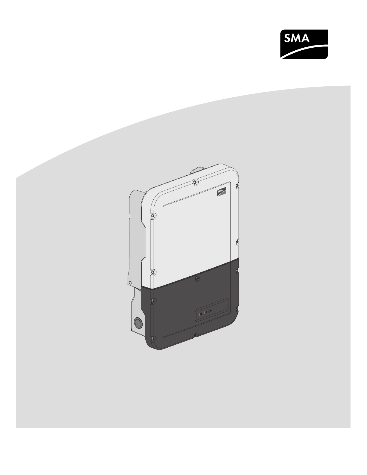
4 Product Overview .................................................................... 14
4.1 Product Description.................................................................................................... 14
4.2 Interfaces and Functions ............................................................................................ 17
4.3 LED Signals................................................................................................................. 20
4.4 System Structure......................................................................................................... 21
5 Mounting................................................................................... 23
5.1 Requirements for Mounting ....................................................................................... 23
5.2 Mounting the Inverter................................................................................................. 26
6 Electrical Connection ................................................................ 29
6.1 Overview of the Connection Area............................................................................ 29
6.1.1 View from Below..................................................................................... 29
6.1.2 Interior View............................................................................................ 30
6.2 AC Connection........................................................................................................... 31
6.2.1 Requirements for the AC Connection.................................................... 31
6.2.2 Connecting the Inverter to the Utility Grid ............................................ 32
6.2.3 Connecting Additional Grounding........................................................ 35
6.3 Connecting the Network Cables............................................................................... 36
6.4 Connecting the energy meter.................................................................................... 37
6.5 Connecting the Data Cable of the Battery and Communication Cable of the
Automatic Transfer Switch ......................................................................................... 38
6.6 Connecting the Switch and Outlet for Secure Power Supply Operation ............... 41
6.7 Connecting Switch for black start (in battery-backup systems)............................... 44

Table of Contents
SMA Solar Technology AG
Operating manualSBSxx-10-BE-en-104
6.8 DC Connection........................................................................................................... 45
6.8.1 Requirements for the DC Connection.................................................... 45
6.8.2 Connecting the power cable of the battery.......................................... 46
7 Commissioning ......................................................................... 48
7.1 Commissioning Procedure ......................................................................................... 48
7.2 Commissioning the Inverter........................................................................................ 48
7.3 Selecting a configuration option............................................................................... 50
8 Operation ................................................................................. 53
8.1 Establishing a connection to the user interface ........................................................ 53
8.1.1 Establishing a Direct Connection via Ethernet ...................................... 53
8.1.2 Establishing a direct connection via WLAN ......................................... 53
8.1.3 Establishing a Connection via Ethernet in the local network ............... 55
8.1.4 Establishing a Connection via WLAN in the Local Network ............... 56
8.2 Logging In and Out of the User Interface................................................................. 57
8.3 Start Page Design of the User Interface.................................................................... 58
8.4 Displaying and Downloading the Stored Data........................................................ 60
8.5 Starting the Installation Assistant............................................................................... 61
8.6 Secure Power Supply Operation .............................................................................. 62
8.6.1 Activating Secure Power Supply Operation......................................... 62
8.6.2 Deactivating Secure Power Supply Operation..................................... 63
8.7 Activate WPS Function............................................................................................... 63
8.8 Switching WLAN On and Off................................................................................... 64
8.9 Changing the Password............................................................................................. 64
8.10 Changing Operating Parameters.............................................................................. 65
8.11 Configuring the Country Data Set............................................................................. 66
8.12 Configuring Feed-In Management............................................................................ 66
8.13 Configuring the Modbus Function............................................................................. 67
8.14 Activating the Receipt of Control Signals (Only for Italy)........................................ 68
8.15 Deactivating Grounding Conductor Monitoring...................................................... 69
8.16 Configuring the Energy Meter................................................................................... 69
8.17 Saving the Configuration in a File............................................................................. 69
8.18 Adopting a Configuration from a File....................................................................... 70
8.19 Updating the Firmware.............................................................................................. 70
9 Disconnecting the Inverter from Voltage Sources ................. 72
10 Cleaning the Inverter ............................................................... 73
11 Troubleshooting........................................................................ 74
11.1 Forgotten Password.................................................................................................... 74

Table of Contents
SMA Solar Technology AG
Operating manual SBSxx-10-BE-en-10 5
11.2 Event Messages ......................................................................................................... 75
12 Decommissioning the Inverter.................................................116
13 Technical Data .......................................................................... 119
14 Contact ......................................................................................124
15 EU Declaration of Conformity .................................................127
1 Information on this Document
SMA Solar Technology AG
Operating manualSBSxx-10-BE-en-106
1 Information on this Document
1.1 Validity
This document is valid for:
• SBS3.7-10 (SunnyBoyStorage 3.7)
• SBS5.0-10 (SunnyBoyStorage 5.0)
• SBS6.0-10 (SunnyBoyStorage 6.0)
1.2 Target Group
This document is intended for qualified persons and end users. Only qualified persons are allowed
to perform the activities marked in this document with a warning symbol and the caption
"Qualifiedperson". Tasks that do not require any particular qualification are not marked and can
also be performed by end users. Qualified persons must have the following skills:
• Knowledge of how batteries work and are operated
• Training in how to deal with the dangers and risks associated with installing, repairing and
using electrical devices, batteries and installations
• Training in the installation and commissioning of electrical devices and installations
• Knowledge of all applicable laws, standards and directives
• Knowledge of and compliance with this document and all safety information
• Knowledge of and compliance with the documents of the battery manufacturer with all safety
information
1.3 Content and Structure of this Document
This document describes the mounting, installation, commissioning, configuration, operation,
troubleshooting and decommissioning of the product as well as the operation of the product user
interface.
You will find the latest version of this document and further information on the product in PDF format
at www.SMA-Solar.com.
Illustrations in this document are reduced to the essential information and may deviate from the real
product.
1.4 Levels of warning messages
The following levels of warning messages may occur when handling the product.
DANGER
Indicates a hazardous situation which, if not avoided, will result in death or serious injury.
WARNING
Indicates a hazardous situation which, if not avoided, could result in death or serious injury.
1 Information on this Document
SMA Solar Technology AG
Operating manual SBSxx-10-BE-en-10 7
CAUTION
Indicates a hazardous situation which, if not avoided, could result in minor or moderate injury.
NOTICE
Indicates a situation which, if not avoided, can result in property damage.
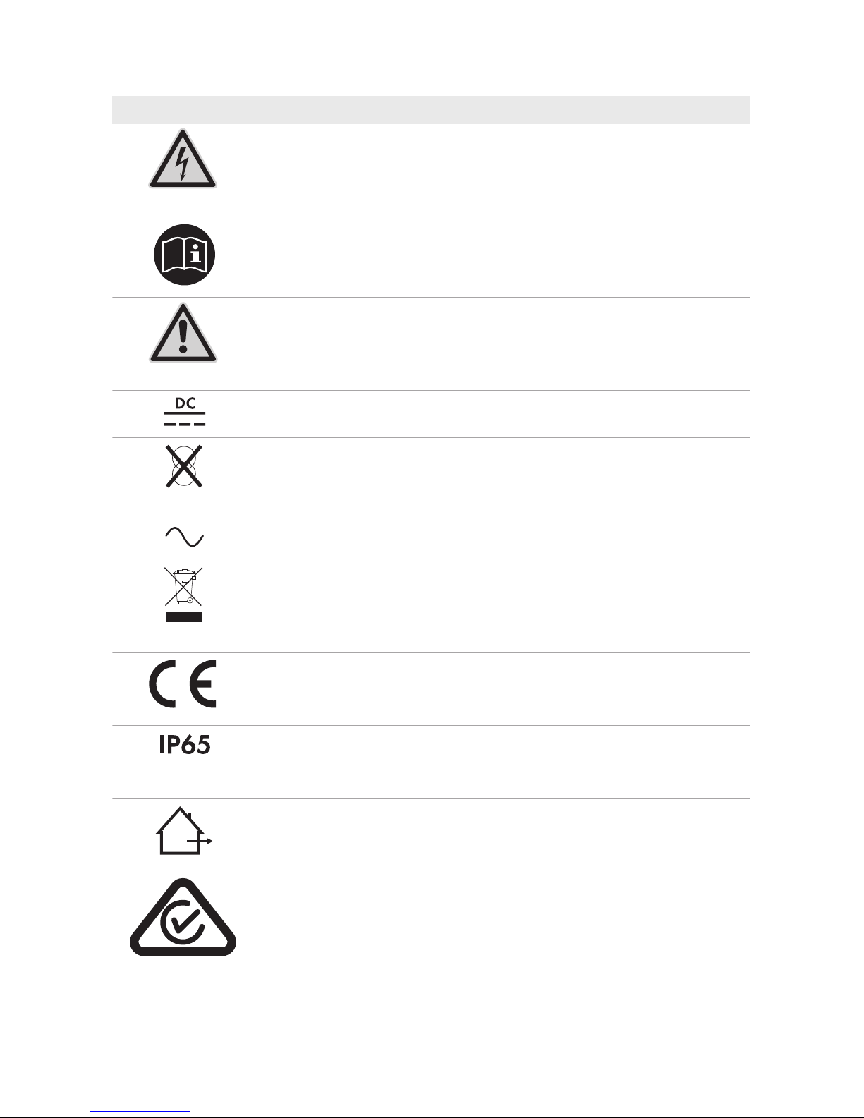
1.5 Symbols in the Document
Symbol Explanation
Information that is important for a specific topic or goal, but is not safety-relevant
Example
☐
Indicates a requirement for meeting a specific goal
☑
Desired result
✖
A problem that might occur
Sections describing activities to be performed by qualified persons only
1.6 Typographies in the document
Typography Use Example
bold
• Messages
• Terminals
• Elements on a user interface
• Elements to be selected
• Elements to be entered
• Connect the insulated
conductors to the terminals
X703:1 to X703:6.
• Enter 10 in the field
Minutes.
>
• Connects several elements to be
selected
• Select Settings > Date.
[Button]
[Key]
• Button or key to be selected or
pressed
• Select [Enter].
1.7 Designation in the document
Complete designation Designation in this document
SunnyBoyStorage Inverter, product

1 Information on this Document
SMA Solar Technology AG
Operating manualSBSxx-10-BE-en-108
1.8 Additional Information
For more information, please go to www.SMA-Solar.com.
Title and information content Type of information
"Approved batteries and battery communication connection"
Overview of approved batteries
Technical Information
"Application for SMAGridGuard Code" Form
"SMASmartHome"
The System Solution for Greater Independence
Planning Guidelines
"Efficiency and Derating"
Efficiency and derating behavior of the SMA inverters
Technical Information
"Parameters and Measured Values"
Overview of all inverter operating parameters and their configura-
tion options
Technical Information
"SMA Modbus® Interface"
List with the product specific SMA Modbus registers
Technical Information
"SMAModbus® Interface"
Information on the commissioning and configuration of the SMA
Modbus interface
Technical Information
"SunSpec® Modbus® Interface"
List with the product specific SunSpec Modbus registers
Technical Information
"SunSpec® Modbus® Interface"
Information on the commissioning and configuration of the SunSpec
Modbus interface
Technical Information

2 Safety
SMA Solar Technology AG
Operating manual SBSxx-10-BE-en-10 9
2 Safety
2.1 Intended Use
The SunnyBoyStorage is an AC-coupled battery inverter for parallel grid and stand-alone mode
operation. The SunnyBoyStorage converts the direct current supplied by a battery into gridcompliant alternating current. The SunnyBoyStorage, together with a battery and a compatible
energy meter, make up a system for increased self-consumption (FlexibleStorageSystem) or,
together with a automatic transfer switch compatible with SunnyBoyStorage, a battery-backup
system (FlexibleStorageSystem with battery-backup function).
The product must only be used as stationary equipment.
The product is suitable for indoor and outdoor use.
The product may only be operated with one of the energy meters approved by SMA Solar
Technology AG. An updated list of energy meters approved by SMA Solar Technology AG is
available at www.SMA-Solar.com.
The product must only be operated in connection with an intrinsically safe lithium-ion battery
approved by SMA Solar Technology AG. An updated list of batteries approved by SMA Solar
Technology AG is available at www.SMA-Solar.com.
The battery must comply with the locally applicable standards and directives and must be
intrinsically safe (see technical information "SMA Flexible Storage System - Detailed explanations of
the safety concept" for detailed explanations regarding the safety concept of battery inverters by
SMA Solar Technology AG).
The communication interface of the used battery must be compatible with the product. The entire
battery voltage range must be completely within the permissible input voltage range of the product.
The maximum permissible DC input voltage of the product must not be exceeded.
The product is not suitable for supplying life-sustaining medical devices. A power outage must not
lead to personal injury.
All components must remain within their permitted operating ranges and their installation
requirements at all times.
The product must only be used in countries for which it is approved or released by SMA Solar
Technology AG and the grid operator.
Use this product only in accordance with the information provided in the enclosed documentation
and with the locally applicable standards and directives. Any other application may cause
personal injury or property damage.
Alterations to the product, e.g. changes or modifications, are only permitted with the express written
permission of SMA Solar Technology AG. Unauthorized alterations will void guarantee and
warranty claims and in most cases terminate the operating license. SMA Solar Technology AG
shall not be held liable for any damage caused by such changes.
Any use of the product other than that described in the Intended Use section does not qualify as the
intended use.
The enclosed documentation is an integral part of this product. Keep the documentation in a
convenient place for future reference and observe all instructions contained therein.
The type label must remain permanently attached to the product.
2 Safety
SMA Solar Technology AG
Operating manualSBSxx-10-BE-en-1010
2.2 Safety Information
This section contains safety information that must be observed at all times when working on or with
the product.
To prevent personal injury and property damage and to ensure long-term operation of the product,
read this section carefully and observe all safety information at all times.
DANGER
Danger to life from electric shock due to live DC cables at the battery.
The DC cables connected to a battery may be live. Touching the DC conductors or the live
components leads to lethal electric shocks.
• Do not touch non-insulated cable ends.
• Do not touch any live components.
• Have the inverter and the battery mounted, installed and commissioned only by qualified
persons with the appropriate skills.
• Observe all safety information of the battery manufacturer.
• Prior to performing any work on the inverter or the battery, disconnect the inverter from all
voltage sources as described in this document.
• Wait five minutes before working on the inverter.
• If an error occurs, have it rectified by qualified persons only.
WARNING
Risk of burns due to electric arcs
Short-circuit currents in the battery can cause heat build-up and electric arcs.
• Disconnect the battery from all voltages sources prior to performing any work on the
battery.
• Observe safety information of the battery manufacturer when working on the battery or
inverter.
CAUTION
Risk of burns from hot surfaces
The surface of the inverter can get very hot. Touching the surface can result in burns.
• Mount the inverter in such a way that it cannot be touched inadvertently.
• Do not touch hot surfaces.
• Wait 30 minutes for the surface to cool sufficiently.
• Observe the safety messages on the inverter.
2 Safety
SMA Solar Technology AG
Operating manual SBSxx-10-BE-en-10 11
NOTICE
Damage to the enclosure seal in subfreezing conditions
If you open the product when temperatures are below freezing, the enclosure seals can be
damaged. Moisture can penetrate the product then.
• Only open the product if the ambient temperature is not below 0°C.
• If a layer of ice has formed on the enclosure seal when temperatures are below freezing,
remove it prior to opening the product (e.g. by melting the ice with warm air). Observe the
applicable safety regulations.
NOTICE
Damage due to sand, dust and moisture ingress
Sand, dust and moisture penetration can damage the product and impair its functionality.
• Only open the product if the humidity is within the thresholds and the environment is free of
sand and dust.
• Do not open the product during a dust storm or precipitation.
NOTICE
Damage due to cleaning agents
The use of cleaning agents may cause damage to the product and its components.
• Clean the product and all its components only with a cloth moistened with clear water.
NOTICE
Damage to the inverter due to electrostatic discharge
Touching electronic components can cause damage to or destroy the inverter through
electrostatic discharge.
• Ground yourself before touching any component.
3 Scope of Delivery
SMA Solar Technology AG
Operating manualSBSxx-10-BE-en-1012
3 Scope of Delivery
B
TOP
(Name des Gerätes):
Bitte füllen Sie die folgenden Felder aus:
:
T
yp:
Seriennummer:
Datum der Inbetriebnahme:
Anschrift:
Installationsbetrieb
T
yp:
Seriennummer:
Datum der Inbetriebnahme:
Anschrift:
Installationsbetrieb
Gewährleistungs- und Garantiebedingungen
C D
E
F G
H I
J
K L
M
P
QO R S TN U
A
V
W
Figure 1: Components included in the scope of delivery
Position Quantity Designation
A 1 Inverter
B 1 Wall mounting bracket
C 1 Cylindrical screw M5x60
D 1 Quick Reference Guide
E 1 4-pole terminal block for connecting a RS485 energy meter
F 1 Terminal block for the AC connection
G 1 Terminal block for connecting the outlet for secure power supply op-
eration
H 4 6-pole terminal block for connecting the battery communication ca-
bles and the communication cable of the automatic transfer switch
I 1 2-pole terminal block for the switch connection for secure power
supply operation or for black start feature.
J 5 Clamping bracket
K 5 Cylindrical screw M5x16
L 5 Washer M5
M 5 Spring washer M5
N 6 Cable gland and counter nut PG21
O 2 Three-hole cable support sleeve
P 4 Four-hole cable support sleeve

3 Scope of Delivery
SMA Solar Technology AG
Operating manual SBSxx-10-BE-en-10 13
Position Quantity Designation
Q 1 Two-hole cable support sleeve
R 6 Sealing plug for two-hole and three-hole cable support sleeve
S 6 Sealing plug for four-hole cable support sleeve
T 2 Blue jumper
U 2 Red jumper
V 1 Ferrite
W 1 Cable tie
4 Product Overview
SMA Solar Technology AG
Operating manualSBSxx-10-BE-en-1014
4 Product Overview
4.1 Product Description
The SunnyBoyStorage uses the connected battery for the intermediate storage of excess PV
energy in the SMAFlexibleStorageSystem. For this purpose, the SunnyBoyStorage receives the
feed-in data and purchased electricity data from the energy meter. This data is used by the
SunnyBoyStorage to control the charging and discharging of the battery.
The use of an automatic transfer switch is required in the battery-backup system. In the event of grid
failure, the automatic transfer switch disconnects the PV system, loads and the SunnyBoyStorage
from the utility grid and creates a battery-backup grid. The battery-backup grid supplies loads that
should continue to be supplied with electricity in the event of grid failure. In the event of grid failure,
the SunnyBoyStorage supplies the loads with energy after a short switching time. The PV system
supplies additional energy that can be used to supply the loads and charge the battery.
Secure power supply operation in FlexibleStorageSystems with backup
power supply not possible
If the inverter is used in a battery-backup system and connected with an automatic transfer
switch, the secure power supply operation is not available.
B
E
C
G
F
A
D
Figure 2: Design of the inverter
Position Designation
A Power Unit
B Enclosure lid of the Power Unit
C Enclosure lid for the Connection Unit
D Connection Unit
4 Product Overview
SMA Solar Technology AG
Operating manual SBSxx-10-BE-en-10 15
Position Designation
E Type label
The type label uniquely identifies the inverter. The type label must remain
permanently attached to the product. You will find the following information on the type label:
• Inverter device type (Model)
• Serial number of the PowerUnit (S/N)
• Date of manufacture
• Device-specific characteristics
F Additional type label
The additional type label must remain permanently attached to the product. You will find the following information on the additional type label:
• Device type (Model)
• Inverter serial number (S/N)
• Identification key (PIC) for registration in Sunny Portal
• Registration ID (RID) for registration in Sunny Portal
• WLAN password (WPA2-PSK) for the direct connection to the user
interface of the inverter via WLAN
G LEDs
The LEDs indicate the operating state of the inverter.
Symbols on the Product and on the Type Label
Symbol Explanation
Inverter
Together with the green LED, this symbol indicates the operating state of
the inverter.
Observe the documentation
Together with the red LED, this symbol indicates an error.
Data transmission
Together with the blue LED, this symbol indicates the status of the network
connection.
Grounding conductor
This symbol indicates the position for connecting a grounding conductor.
Risk of burns due to hot surfaces
The product can get hot during operation. Avoid contact during opera-
tion. Prior to performing any work on the product, allow the product to
cool down sufficiently.
4 Product Overview
SMA Solar Technology AG
Operating manualSBSxx-10-BE-en-1016
Symbol Explanation
Danger to life due to electric shock
The product operates at high voltages. Prior to performing any work on
the product, disconnect the product from voltage sources. All work on the
product must be carried out by qualified persons only.
Observe the documentation
Observe all documentation supplied with the product.
Danger
This symbol indicates that the product must be additionally grounded if
additional grounding or equipotential bonding is required at the installation site.
Direct current
The product is has no galvanic isolation.
AC
Alternating current
WEEE designation
Do not dispose of the product together with the household waste but in
accordance with the disposal regulations for electronic waste applicable
at the installation site.
CE marking
The product complies with the requirements of the applicable EU direc-
tives.
Degree of protectionIP65
The product is protected against dust intrusion and water jets from any
angle.
The product is suitable for outdoor installation.
RCM (Regulatory Compliance Mark)
The product complies with the requirements of the applicable Australian
standards.

4 Product Overview
SMA Solar Technology AG
Operating manual SBSxx-10-BE-en-10 17
4.2 Interfaces and Functions
The inverter is equipped with the following interfaces and functions:
User interface for monitoring and configuration
The product is equipped as standard with an integrated webserver, which provides a user interface
for configuring and monitoring the product. The product user interface can be called up via the web
browser if there is an existing connection to an end device (e.g. computer, tablet PC or
smartphone).
SMA Speedwire
The product is equipped with SMASpeedwire as standard. SMASpeedwire is a type of
communication based on the Ethernet standard. SMASpeedwire is designed for a data transfer
rate of 100Mbps and enables optimum communication between Speedwire devices within
systems.
SMA Webconnect
The inverter is equipped with a Webconnect function as standard. The Webconnect function
enables direct data transmission between the inverters of a small-scale plant and the Internet portals
SunnyPortal and SunnyPlaces without any additional communication device and for a maximum
of 1 inverters per visualized system. If there is an existing WLAN or Ethernet connection, you can
directly access your visualized system via the web browser on your end device.
WLAN
The product is equipped with a WLAN interface as standard. The inverter is delivered with the
WLAN interface activated as standard. If you do not want to use WLAN, you can deactivate the
WLAN interface.
In addition, the product has a WPS function. The WPS function is for automatically connecting the
product to a network (e.g. via router) and establish a direct connection between the product and
an end device.
Modbus
The product is equipped with a Modbus interface. The Modbus interface is deactivated by default
and must be configured as needed.
The Modbus interface of the supported SMA products is designed for industrial use – via SCADA
systems, for example – and has the following tasks:
• Remote query of measured values
• Remote setting of operating parameters
• Setpoint specifications for system control
• Controlling the battery
Grid management services
The product is equipped with service functions for grid management.
Depending on the requirements of the grid operator, you can activate and configure the functions
(e.g. active power limitation) via operating parameters.

4 Product Overview
SMA Solar Technology AG
Operating manualSBSxx-10-BE-en-1018
Secure power supply operation
In case of a grid failure, the secure power supply operation supplies the loads with energy from the
battery. You can connect a standard outlet and a standard switch to the inverter. You can connect
a load with a maximum of 16A and 230/240V to the outlet. The load is supplied with energy
form the battery during grid failure. The switch is used to activate and deactivate secure power
supply operation.
The secure power supply operation is not automatically activated in the event of a grid failure,
neither is it automatically deactivated once the utility grid is available again. If the utility grid fails,
the load supply must be activated manually by activating the switch. The inverter automatically
regulates the energy supply of the outlet after activating the switch. When the utility grid is
available again and the load can be supplied by this again, the secure power supply operation
must be deactivated manually by switching the switch off.
During active secure power supply operation, the inverter is disconnected from the electricity and
does not therefore feed into the utility grid. During secure power supply operation, the load can
only be supplied with energy as long as there is stored energy available in the battery. If there is
insufficient energy available from the battery, the secure power supply operation remains active,
even if the utility grid is available again. Switching over to supplying the load from the utility grid
does not take place automatically. Once the battery is sufficiently charged again and the load can
be supplied, the secure power supply operation must be restarted.
Secure power supply operation in FlexibleStorageSystems with backup
power supply not possible
If the inverter is used in a battery-backup system and connected with an automatic transfer
switch, the secure power supply operation is not available.
Do not connect any loads that require a stable energy supply
The secure power supply operation and the battery-backup operation may not be used for
loads that require a stable energy supply. The energy that is available during the secure
power supply operation or battery-backup operation depends on the battery capacity
available and the state of charge of the battery (SOC).
• Do not connect loads if they are dependent on a stable energy supply for reliable
operation.
Battery-backup function
The inverter is equipped with a battery-backup function. The battery-backup function is deactivated
by default and must be activated via the user interface. The battery-backup function can only be
activated if the inverter is operated in a battery-backup system with an automatic transfer switch.
The battery-backup function ensures that the inverter forms a battery-backup grid that uses energy
from the battery and the PV system to supply the household grid in the event of a utility grid failure.
When the battery-backup operation is activated, the automatic transfer switch disconnects the PV
system and the household grid from the utility grid in the event of a grid failure, and connects these
to the battery-backup grid. After a short switch-over time, the battery-backup grid and loads
connected can be supplied by the battery and supplemented with energy from the PV system. The
loading of the battery is ensured by the existing PV system. As soon as the utility grid is available

4 Product Overview
SMA Solar Technology AG
Operating manual SBSxx-10-BE-en-10 19
again, the battery-backup operation is deactivated automatically and the loads are supplied with
energy from the utility grid. If the automatic battery-backup operation is not set, the battery-backup
operation must be manually activated in the event of a grid failure, and must also be deactivated
again once the utility grid is available.
An updated list of automatic transfer switches approved by SMA Solar Technology AG is available
at www.SMA-Solar.com.
Secure power supply operation in FlexibleStorageSystems with backup
power supply not possible
If the inverter is used in a battery-backup system and connected with an automatic transfer
switch, the secure power supply operation is not available.
Do not connect any loads that require a stable energy supply
The secure power supply operation and the battery-backup operation may not be used for
loads that require a stable energy supply. The energy that is available during the secure
power supply operation or battery-backup operation depends on the battery capacity
available and the state of charge of the battery (SOC).
• Do not connect loads if they are dependent on a stable energy supply for reliable
operation.
Black start function
The inverter has a black start function and an auxiliary battery that provides energy for the black
start. In battery-backup systems, you have the possibility to install a standard switch for black
starting the inverter and battery. The black-start switch is used to start the battery-backup operation
manually in the event of grid failure if the battery and inverter are in sleep mode and, therefore, are
unable to provide energy. When the black-start switch is switched on manually, the energy from the
auxiliary battery is made available in order to automatically switch the battery and therefore also
the inverter from sleep mode to operation in order that the inverter can make energy available from
the battery. You can stop the battery-backup operation by switching it off manually.
All-pole sensitive residual-current monitoring unit
The all-pole sensitive residual-current monitoring unit detects alternating and direct differential
currents. In single-phase and three-phase inverters, the integrated differential current sensor detects
the current difference between the neutral conductor and the line conductor(s). If the current
difference increases suddenly, the inverter disconnects from the utility grid.
SMA Smart Connected
SMA Smart Connected is the free monitoring of the inverter via the SMA SunnyPortal. Thanks to
SMA Smart Connected, the PV system operator and qualified person will be informed automatically
and proactively about inverter events that occur.
SMA Smart Connected is activated during registration in SunnyPortal. In order to use SMA Smart
Connected, it is necessary that the inverter is permanently connected to SunnyPortal and the data
of the PV system operator and qualified person is stored in SunnyPortal and up-to-date.
4 Product Overview
SMA Solar Technology AG
Operating manualSBSxx-10-BE-en-1020
4.3 LED Signals
LED signal Explanation
The green LED is flashing
(twoseconds on and
twoseconds off)
Waiting for feed-in conditions
The conditions for feed-in operation are not yet met. As soon as the
conditions are met, the inverter will start feed-in operation.
The green LED is flashing
(1.5s on and 0.5s off)
Secure power supply operation or battery-backup function
The secure power supply operation or battery-backup function is ac-
tivated and the inverter supplies the loads with energy from the battery.
The green LED flashes
quickly
Update of central processing unit
The central processing unit of the inverter is being updated.
The green LED is glowing Parallel grid operation
The green LED is off The inverter is not feeding into the utility grid.
The red LED is glowing Event occurred
If an event occurs, a distinct event message and the corresponding
event number will be displayed in addition on the inverter user inter-
face or in the communication product.
The blue LED flashes slowly
for approx. one minute
Communication connection is being established
The inverter is establishing a connection to a local network or is es-
tablishing a direct connection to an end device via Ethernet (e.g.
computer, tablet PC or smartphone).
The blue LED flashes quickly
for approx. two minutes.
WPS active
The WPS function is active.
The blue LED is glowing Communication active
There is an active connection with a local network or there is a di-
rect connection with an end device via Ethernet (e.g. computer,
tablet PC or smartphone).
4 Product Overview
SMA Solar Technology AG
Operating manual SBSxx-10-BE-en-10 21
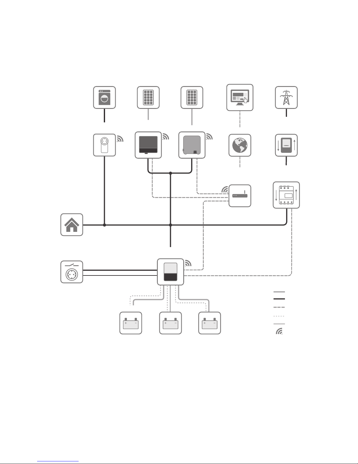
4.4 System Structure
Flexible Storage System
SUNNY PORTAL/
SUNNY PLACES
INTERNET
230 V / 16 A
SUNNY
TRIPOWER
SUNNY BOY
SUNNY BOY
STORAGE
ENERGY METER/
SUNNY HOME
MANAGER 2.0
Speedwire/
Ethernet
CAN
Com
UTILITY GRID
PV
GENERATOR
BATTERY
ROUTER
(with SWITCH)
UTILITY METER
FOR BILLING
PURPOSES
APPLIANCE
Radio
DC
AC
SECURE
POWER SUPPLY
APPLIANCE
RADIO-CONTROLLED
SOCKET
PV
GENERATOR
Figure 3: System design of a flexible storage system with switch and outlet for secure power supply operation
(example)
4 Product Overview
SMA Solar Technology AG
Operating manualSBSxx-10-BE-en-1022
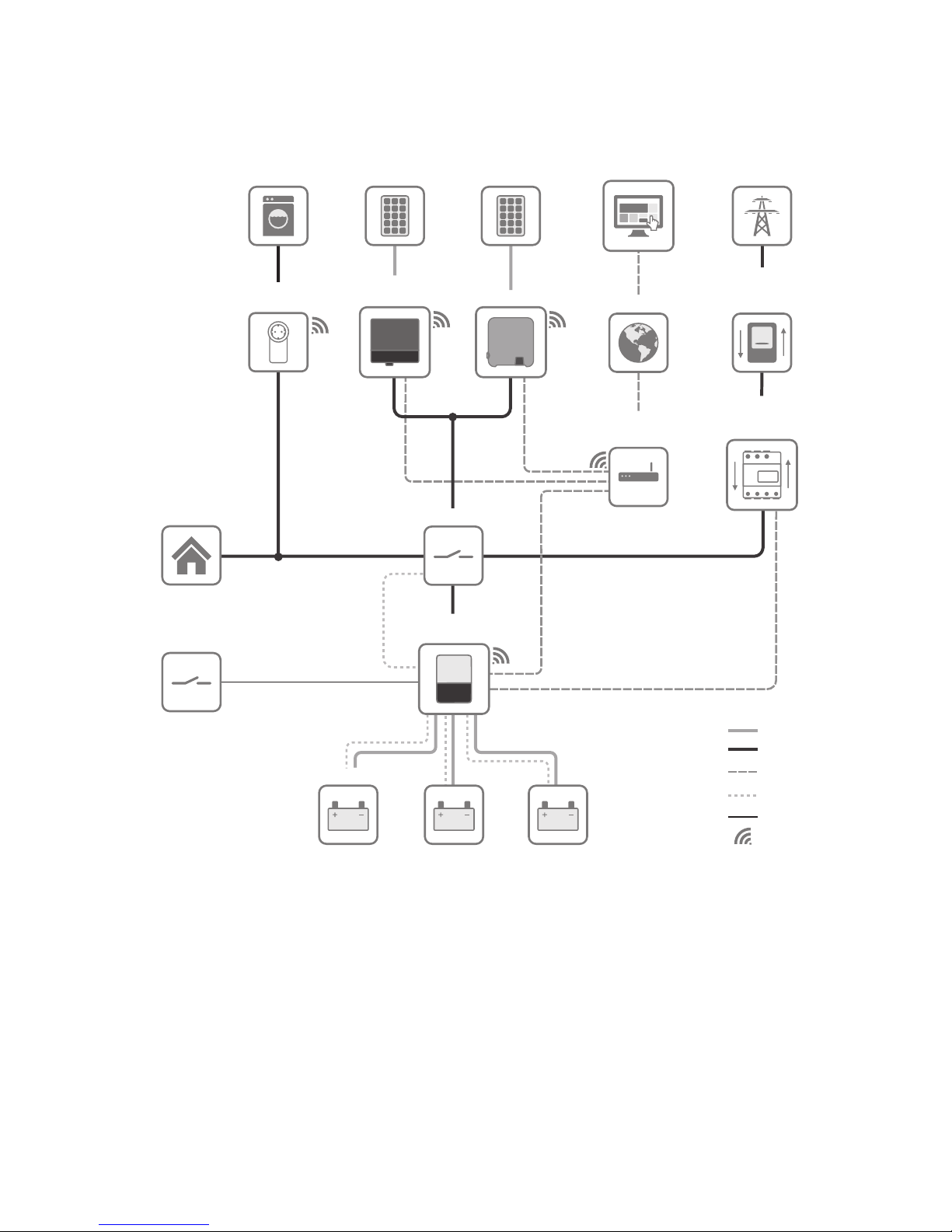
SMAFlexibleStorageSystem with Battery-Backup Function
SUNNY PORTAL/
SUNNY PLACES
INTERNET
ENERGY METER/
SUNNY HOME
MANAGER 2.0
Speedwire/
Ethernet
CAN
SUNNY
TRIPOWER
SUNNY BOY
BACKUP
SUNNY BOY
STORAGE
Com
UTILITY GRID
BATTERY
ROUTER
(with SWITCH)
UTILITY METER
FOR BILLING
PURPOSES
APPLIANCE
Radio
AC
DC
APPLIANCE
RADIO-CONTROLLED
SOCKET
PV
GENERATOR
PV
GENERATOR
BLACK START
SWITCH
Figure 4: System design of a flexible storage system with battery-backup function (example)
5 Mounting
SMA Solar Technology AG
Operating manual SBSxx-10-BE-en-10 23
5 Mounting
5.1 Requirements for Mounting
Requirements for the mounting location:
WARNING
Danger to life due to fire or explosion
Despite careful construction, electrical devices can cause fires.
• Do not mount the product in areas containing highly flammable materials or gases.
• Do not mount the product in potentially explosive atmospheres.
☐ The mounting location must be inaccessible to children.
☐ A solid support surface must be available for mounting, e.g. concrete or masonry. When
mounted on drywall or similar materials, the inverter emits audible vibrations during operation
which could be perceived as annoying.
☐ The mounting location must be suitable for the weight and dimensions of the inverter (see
Section13 "Technical Data", page119).
☐ The mounting location must not be exposed to direct solar irradiation. If the inverter is exposed
to direct solar irradiation, the exterior plastic parts might age prematurely and overheating
might occur. When becoming too hot, the inverter reduces its power output to avoid
overheating.
☐ The mounting location should be freely and safely accessible at all times without the need for
any auxiliary equipment (such as scaffolding or lifting platforms). Non-fulfillment of these
criteria may restrict servicing.
☐ To ensure optimum operation, the ambient temperature should be between -25°C and
+45°C.
☐ Climatic conditions must be met (see Section13 "Technical Data", page119).
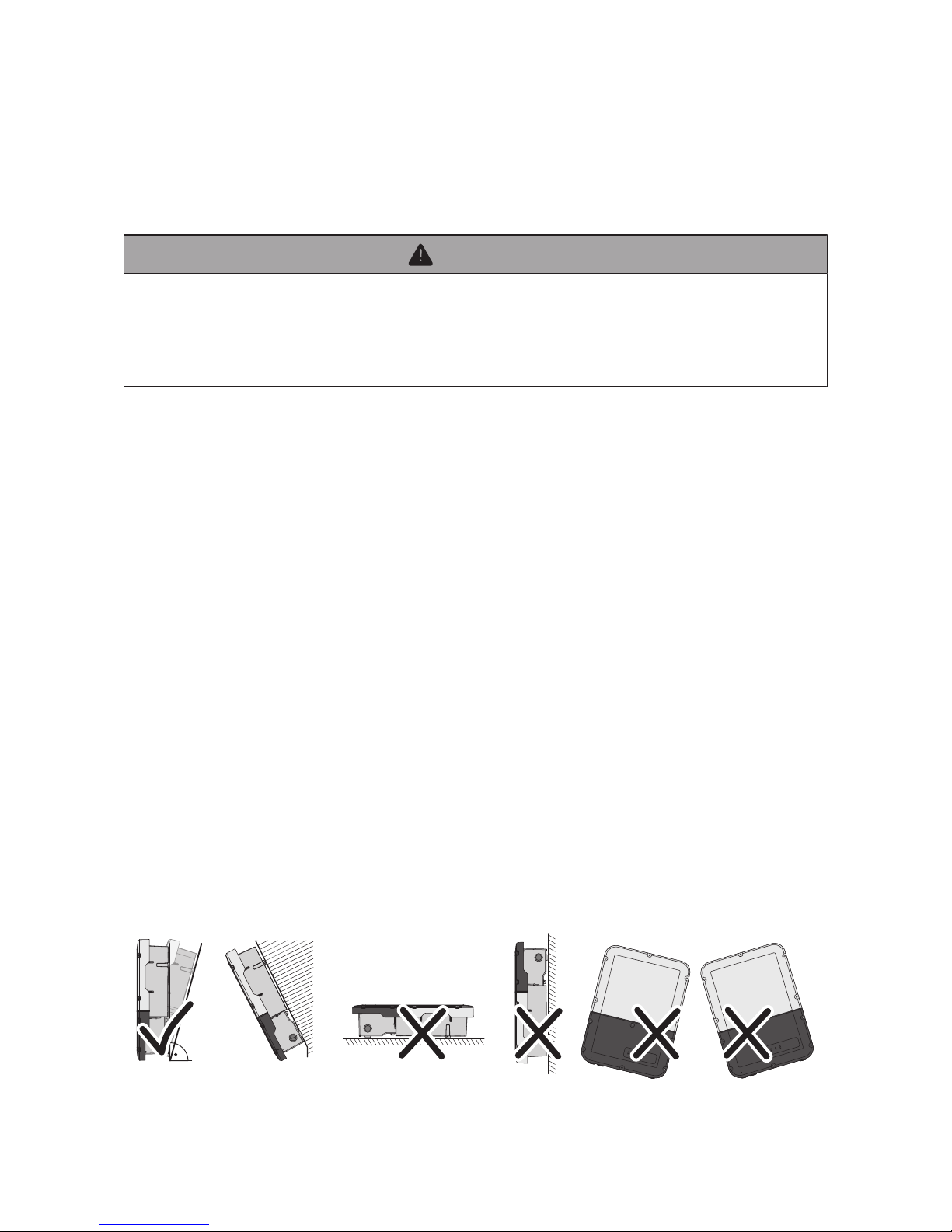
Permitted and prohibited mounting positions:
☐ The inverter must only be mounted in one of the permitted positions. This will ensure that no
moisture can penetrate the inverter.
☐ The inverter should be mounted in such a way that the LED signals can be read without
difficulty.
15°
Figure 5: Permitted and prohibited mounting positions
5 Mounting
SMA Solar Technology AG
Operating manualSBSxx-10-BE-en-1024
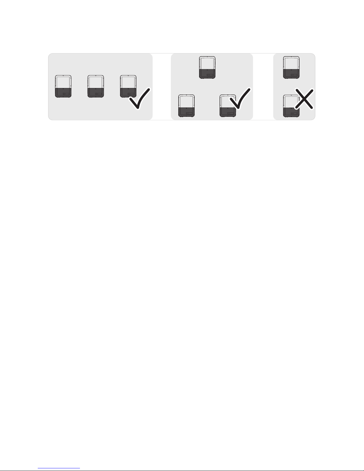
☐ Do not mount multiple inverters directly above one another.
Figure 6: Permissible and impermissible mounting positions of multiple inverters
5 Mounting
SMA Solar Technology AG
Operating manual SBSxx-10-BE-en-10 25
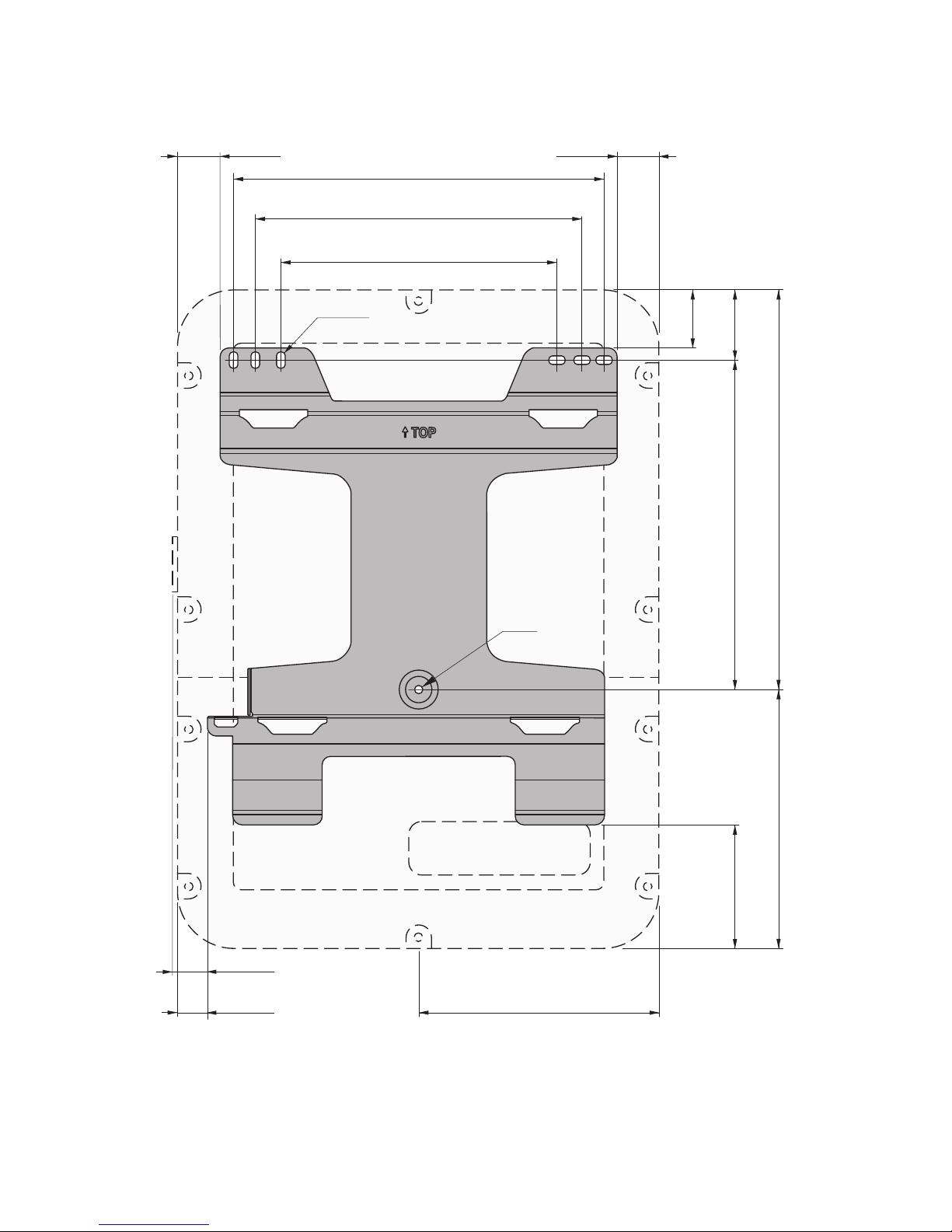
Dimensions for mounting:
365
Ø 9
9 x 18
61
411
46 46
140
290
266
306
32.8
34.4
362.4
439.6
74.6
Figure 7: Position of the anchoring points(Dimensions in mm)
5 Mounting
SMA Solar Technology AG
Operating manualSBSxx-10-BE-en-1026
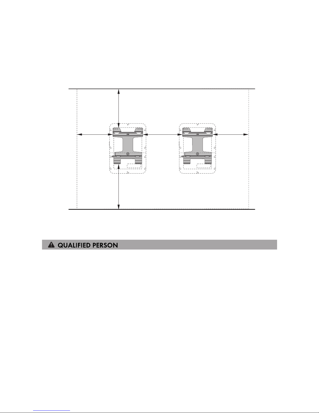
Recommended Clearances:
If you maintain the recommended clearances, adequate heat dissipation will be ensured. Thus, you
will prevent power reduction due to excessive temperature.
☐ Maintain the recommended clearances to walls as well as to other inverters or objects.
☐ If multiple inverters are mounted in areas with high ambient temperatures, increase the
clearances between the inverters and ensure sufficient fresh-air supply.
700 600
550
600
550
Figure 8: Recommended clearances(Dimensions in mm)
5.2 Mounting the Inverter
Additionally required mounting material (not included in the scope of delivery):
☐ Three screws suitable for the support surface (diameter: 8mm)
☐ Three washers suitable for the screws
☐ Where necessary, 3 screw anchors suitable for the support surface and the screws
☐ To secure the inverter against theft: one padlock suitable for outdoor use
Padlock dimensions:
• Diameter of the shackle: 8mm to 10mm
• Width of the shackle (inner dimension): 30mm to 40mm
• Height of the shackle (inner dimension): 30mm to 40mm
5 Mounting
SMA Solar Technology AG
Operating manual SBSxx-10-BE-en-10 27
CAUTION
Risk of injury when lifting the inverter, or if it is dropped
The inverter weighs 26kg. There is risk of injury if the inverter is lifted incorrectly or dropped
while being transported or when attaching it to or removing it from the wall mounting bracket.
• Transport and lift the inverter carefully.
The Connection Unit and Power Unit can be disconnected from one another
to make mounting easier
If the local conditions make it difficult to mount the entire inverter, you can disconnect the
Connection Unit and Power Unit from each other if the ambient temperature is at least 0°C
and there is no frost. This way, you can transport each enclosure part and also attach to the
wall mounting bracket individually. Then, during assembly, both enclosure parts must be joined
again. A detailed description for how to disconnect the Connection Unit and Power Unit from
each other and to individually mount them to the wall mounting bracket can be found on the
Internet under www.SMA-Solar.com.
Procedure:
1.
CAUTION
Risk of injury due to damaged cables
There may be power cables or other supply lines (e.g. gas or water) routed in the wall.
• Ensure that no lines are laid in the wall which could be damaged when drilling holes.
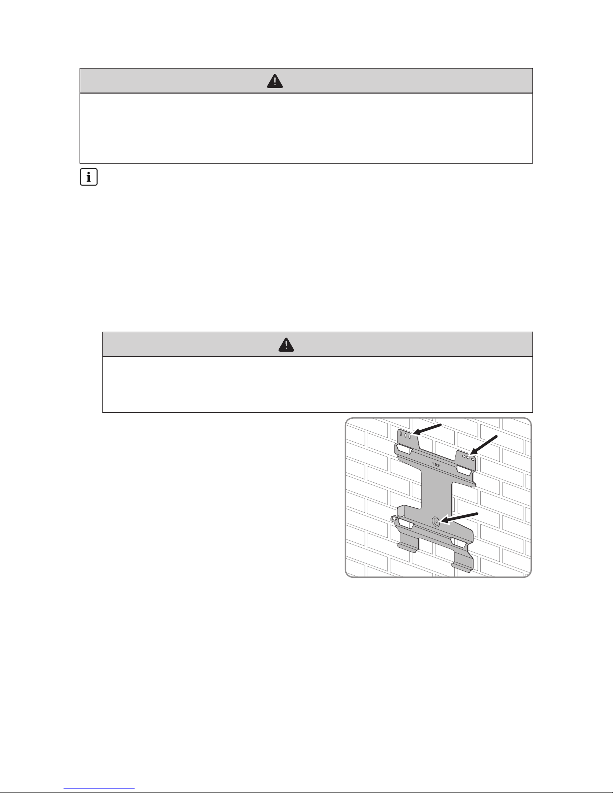
2. Align the wall mounting bracket horizontally on the
wall and use it to mark the position of the drill holes.
Here, use at least one hole each, to the right and
left, and the hole at the bottom center.
3. Set the wall mounting bracket aside and drill the marked holes.
4. Insert screw anchors into the drill holes if the support surface requires them.
5. Secure the wall mounting bracket horizontally using screws and washers.
5 Mounting
SMA Solar Technology AG
Operating manualSBSxx-10-BE-en-1028
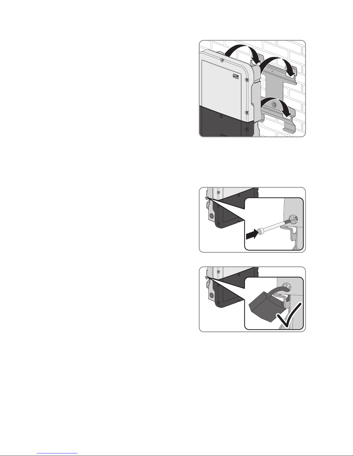
6. Hook the inverter into the wall mounting bracket.
Here, the lugs on the rear side of the Power Unit
must be hooked into the upper recesses and the lugs
in the Connection Unit into the lower recesses in the
wall mounting bracket.
TOP
7. Check whether the inverter is securely in place.
If the Connection Unit can be moved forward, the lugs on the rear side of the Connection Unit
are not hooked into the lower recesses in the wall mounting bracket. Remove the inverter from
the wall mounting bracket and hook it in again.
Once the Connection Unit cannot be moved forward, the inverter is securely in place.
8. Secure the inverter to the wall mounting bracket. To
do this, insert the screw M5x60 through the hole on
the left side of the Power Unit using a Torx
screwdriver (TX25) and screw it into the thread
(torque: 1.7Nm ± 0.3Nm).
9. If the inverter is to be protected against theft, attach a padlock:
• To do this, guide the shackle of the padlock
through the provided hole on the left side of the
Power Unit and close the shackle.
• Keep the key of the padlock in a safe place.
6 Electrical Connection
SMA Solar Technology AG
Operating manual SBSxx-10-BE-en-10 29
6 Electrical Connection
6.1 Overview of the Connection Area
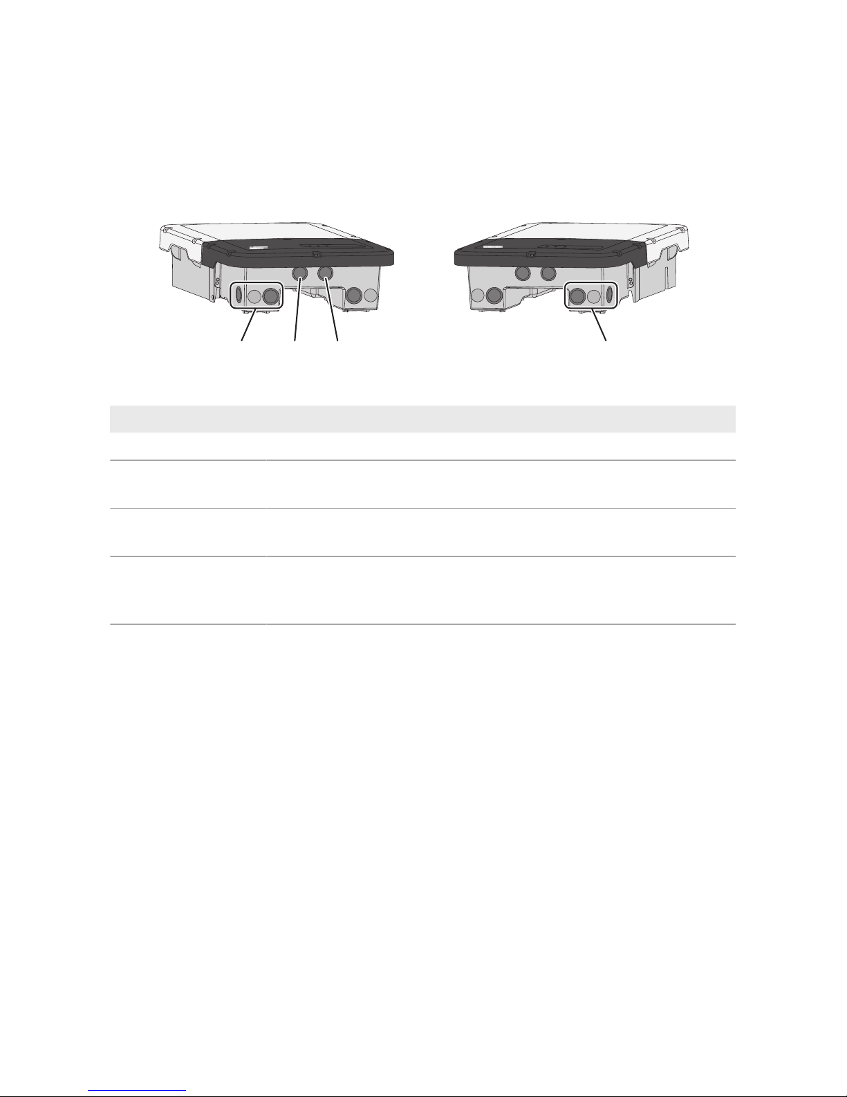
6.1.1 View from Below
B
A C D
Figure 9: Enclosure openings at the bottom of the inverter
Position Designation
A Enclosure opening for the DC connection
B Enclosure opening for the battery communication cable of the Antenna
Extension Kit (optional)
C Enclosure opening for the network cables and, if needed, for other data
cables
D Enclosure opening for the AC connection and the connection cables of
the outlet and of the switch for the secure power supply operation or for
the signal cable for the black start
6 Electrical Connection
SMA Solar Technology AG
Operating manualSBSxx-10-BE-en-1030
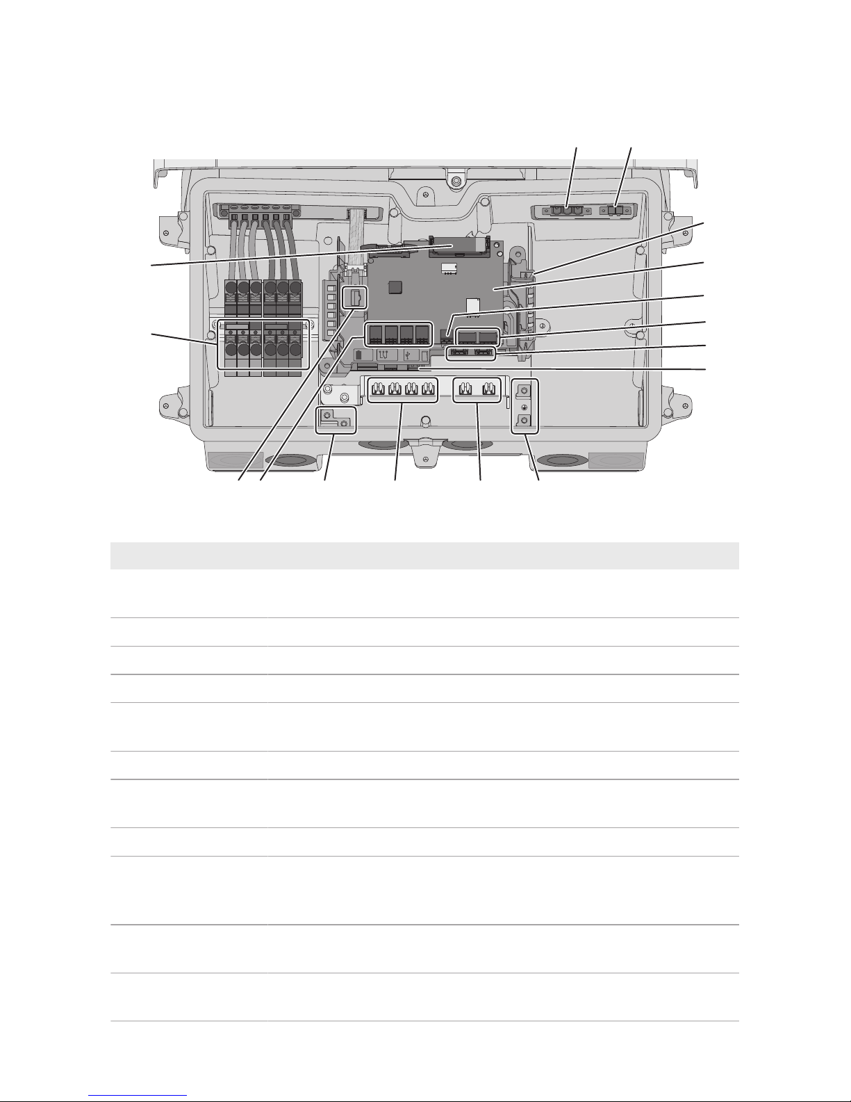
6.1.2 Interior View
COM
DC-in
SPS
AC-out
D-IN
SPS
A B
M1
X1 X2
M2
ANT.
FCC ID: SVF-KP20
IC: 9440A-KP20
Max. 30V DC
DISPLAY
BAT MFR
USB
+
_
B
D
I
O
A
C
F
JK
H
L
MN
E
G
P
Figure 10: Connection areas in the interior of the inverter
Position Designation
A
Slot AC-out for den direct connection of the utility grid or of the AC electric circuit via the automatic transfer switch
B
SPS slot for connecting the secure power supply outlet
C Communication assembly
D Interface module of the battery
E Jack for the switch connection for secure power supply operation or
black-start function
F No function
G
Network ports A and B for connecting a router or network switch and for
connecting an SMAEnergyMeter
H
USB port for connecting a USB flash drive (for service purposes)
I Grounding point for the grounding conductor of the utility grid, the outlet
for secure power supply operation and, if necessary, an additional
grounding or for the equipotential bonding
J Shield clamps for the connection of the cable shields of the RS485 com-
munication cables
K Shield clamps for the connection of the cable shields of the battery com-
munication cables
 Loading...