

Page 1
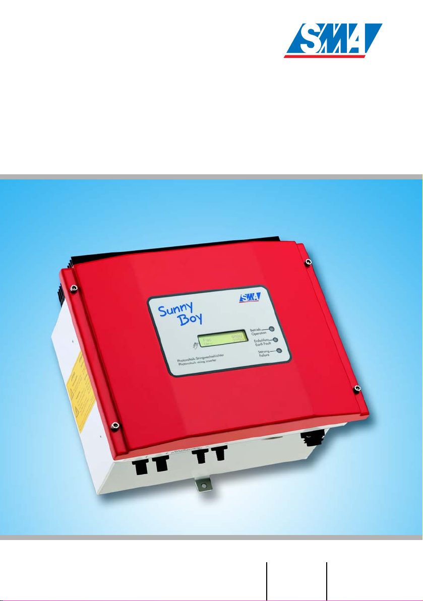
Sunny Boy 700
String Inverter Sunny Boy 700
Installation Guide Version 1.1 SB700-11:SA2006
Page 2

Page 3
SMA Technologie AG Explanation of Symbols used in this Document
Explanation of Symbols used in this Document
This symbol indicates information that is essential for a trouble-free
and safe operation of the product. Please read these sections carefully in order to avoid any damages of the equipment and for optimal personal protection.
This symbol indicates information that is required for the optimal operation of
the product. Read these sections carefully in order to ensure an optimal operation of the product and all its features.
This symbol indicates an example.
Installation Guide SB700-11:SA2006 Page 3
Page 4

Legal Restrictions SMA Technologie AG
Liability exclusion
The information contained in this documentation are the property of SMA Technologie AG. No part of this
documentation may be published without written permission from SMA Technologie AG. A reproduction for
internal purposes for the evaluation of the product or an appropriate application is permitted and does not
require authorization.
All information are based on our "General Terms and Conditions of Delivery of SMA Technologie AG”.
The content of this documentation is reviewed continuously and adjusted, if necessary. SMA Technologie
AG provides this documentation without exclusion of deviations and without warranty of completeness. You
will find the current version on the Internet at www.SMA.de or can obtain it via the usual sales channels.
Warranty or liability claims for all kinds are excluded in case of damages due to:
• Inappropriate use of the product
• Operation of the product in an improper environment
• Operation of the product without considering the relevant safety regulations
• Non-fulfillment of the warnings or safety instructions described in the documentation for the product
• Operation of the product under faulty conditions concerning security and protection
• Arbitrary changing of the product or the provided software
• Failure of the product due to interference of connected or contiguous devices out of legal limit values
• Disasters and force majeure
Software Licensing
The use of the provided software by SMA Technologie AG is subject to the following conditions:
The software may be reproduced for internal purposes and installed on any number of computers. Provided
source codes can be changed and adjusted on the company’s own authority according to the internal
purpose. Driver may be ported to other operating systems as well. No part of the source codes may be
published without written permission of SMA Technologie AG. Sublicensing of the software is not
acceptable.
Liability limitation: SMA Technologie AG disclaims liability for any direct or indirect consequential damages
arising from the use of the software produced by SMA Technologie AG. The same applies for the provision
and/or non-provision of support.
Provided software not produced by SMA Technologie AG is subject to the respective licensing and liability
agreements of the manufacturer.
Trademarks
All brand and product names used herein are trademarks or registered trademarks of their respective
holders, although they may not be specifically designated as such.
SMA Technologie AG
Hannoversche Strasse 1-5
34266 Niestetal
Germany
Tel. (+49) 5 61 95 22 – 0
Fax (+49) 5 61 95 22 – 100
www.SMA.de
E-Mail: info@SMA.de
© 2005 SMA Technologie AG. All rights reserved.
Page 4 SB700-11:SA2006 Installation Guide
Page 5

SMA Technologie AG Table of Contents
Table of Contents
1 Foreword . . . . . . . . . . . . . . . . . . . . . . . . . . . . . . . . . 7
2 Safety information . . . . . . . . . . . . . . . . . . . . . . . . . . . 9
3 Overview . . . . . . . . . . . . . . . . . . . . . . . . . . . . . . . . 11
3.1 Unit description . . . . . . . . . . . . . . . . . . . . . . . . . . . . . . . . . . .11
3.2 External dimensions. . . . . . . . . . . . . . . . . . . . . . . . . . . . . . . .12
4 Installation requirements . . . . . . . . . . . . . . . . . . . . . 13
4.1 Installation site requirements . . . . . . . . . . . . . . . . . . . . . . . . .13
4.2 PV generator requirements. . . . . . . . . . . . . . . . . . . . . . . . . . .15
4.3 Low voltage grid 230 V (AC). . . . . . . . . . . . . . . . . . . . . . . . .15
5 Installation . . . . . . . . . . . . . . . . . . . . . . . . . . . . . . . 19
5.1 Mounting the unit . . . . . . . . . . . . . . . . . . . . . . . . . . . . . . . . .19
5.2 Electrical installation . . . . . . . . . . . . . . . . . . . . . . . . . . . . . . .20
5.3 Setting the input voltage . . . . . . . . . . . . . . . . . . . . . . . . . . . .27
5.4 Startup . . . . . . . . . . . . . . . . . . . . . . . . . . . . . . . . . . . . . . . . .30
6 Opening and closing the Sunny Boy . . . . . . . . . . . . 33
6.1 Opening the Sunny Boy. . . . . . . . . . . . . . . . . . . . . . . . . . . . .33
6.2 Closing the Sunny Boy. . . . . . . . . . . . . . . . . . . . . . . . . . . . . .33
7 Technical data. . . . . . . . . . . . . . . . . . . . . . . . . . . . . 35
7.1 Input voltage range 119 ... 250 V DC . . . . . . . . . . . . . . . . . .35
7.1.1 PV generator connection data . . . . . . . . . . . . . . . . . . . . .35
7.1.2 Grid connection data . . . . . . . . . . . . . . . . . . . . . . . . . . .35
7.2 Input voltage range 96 ... 200 V DC . . . . . . . . . . . . . . . . . . .36
7.2.1 PV generator connection data . . . . . . . . . . . . . . . . . . . . .36
7.2.2 Grid connection data . . . . . . . . . . . . . . . . . . . . . . . . . . .36
7.3 Input voltage range 73 ... 150 V DC . . . . . . . . . . . . . . . . . . .37
7.3.1 PV generator connection data . . . . . . . . . . . . . . . . . . . . .37
7.3.2 Grid connection data . . . . . . . . . . . . . . . . . . . . . . . . . . .37
7.4 Device description. . . . . . . . . . . . . . . . . . . . . . . . . . . . . . . . .38
7.5 Operating parameters . . . . . . . . . . . . . . . . . . . . . . . . . . . . . .39
8 Replacing the varistors. . . . . . . . . . . . . . . . . . . . . . . 41
9 Rating for a line circuit breaker. . . . . . . . . . . . . . . . . 45
10 Contact. . . . . . . . . . . . . . . . . . . . . . . . . . . . . . . . . . 49
Installation Guide SB700-11:SA2006 Page 5
Page 6

Table of Contents SMA Technologie AG
Page 6 SB700-11:SA2006 Installation Guide
Page 7

SMA Technologie AG Foreword
1 Foreword
The installation of the Sunny Boy may only be done by qualified
technicians. The installer must be approved by the utility company.
Please read the installation guide carefully before you begin with
the installation. The installation of utility interactive power sources
must be compliant with all applicable regulations of the utility
company and with all applicable regulations and standards.
The Sunny Boy 700 is equipped with the SMA grid guard. This is a type of
independent disconnection device. It ensures that the Sunny Boy 700 complies
with the VDEW (Verband der Elektrizitätswirtschaft – German Electricity
Industry Association) regulations for the connection and parallel operation of
electrical power units to the low-voltage grid of the electricity supply company
and with DIN VDE 0126 (4.99) which is a part of these regulations.
This installation manual is intended solely for qualified electricians. Its aim is to help
install and set up SMA Sunny Boy SB 700 inverters quickly and correctly.
For detailed information on troubleshooting and on how to use the Sunny Boy 700,
including information about the different communication options, please see the
operating instructions.
The „Sunny Design“ tool will help to dimension and check the size of your strings with
respect to the inverter you intend to use. Further information about „Sunny Design“
is available at www.SMA.de.
If your Sunny Boy is equipped with a communication interface, you will find detailed
instructions for installation in the description of the communication interfaces (PiggyBacks), which has been delivered with the device.
If you require further information, please call the Sunny Boy hotline on the following
number:
+49 (0)561 95 22-499
Installation Guide SB700-11:SA2006 Page 7
Page 8

Foreword SMA Technologie AG
Page 8 SB700-11:SA2006 Installation Guide
Page 9
SMA Technologie AG Safety information
2 Safety information
Check your plant configuration and the
string sizing with „Sunny Design“
(available at www.SMA.de) or with the
Sunny Boy Hotline before you start with
the installation. Exceeding the
specifications with the input voltage will
destroy the Sunny Boy. Overvoltage on
Betrieb
Photovoltaik-Stringwechselrichter
Operation
Photovoltaicstringinverter
Erdschluss
Earth
F
ault
Störung
Failure
Work on the Sunny Boy with the lid removed must be carried out
by a qualified electrician. Hazardous and even lethal voltages can
be encountered within the enclosure. Before working on the Sunny
Boy with the lid removed, the AC and DC voltages MUST be
disconnected from the Sunny Boy and it must be sure that all
capacitors are discharged.
The Sunny Boy must be disconnected from the mains and
precautions must be taken to prevent the grid being reconnected.
In addition, the connections to the PV generator must be
disconnected.
the DC side can even cause dangerous
explosions of the Sunny Boys input
capacitors and explosions of the
electrolytes coming from the exploded
capacitors.
After isolating the AC and DC voltage you must wait approx. 30
minutes for the capacitors in the Sunny Boy to discharge. Only then
is it safe to open the unit by removing the lid. You must also make
sure that no voltage is present in the device.
The electronics inside your Sunny Boy 700 is vulnerable in terms of
electrostatic discharge. Be sure to be connected to ground (e.g. the
enclosure of the Sunny Boy) before handling anything within the
enclosure of the Sunny Boy.
This appliance is not intended for use by young children or infirm
persons unless they have been adequately supervised by a
responsible person to ensure that they can use the appliance
safely.
Young children should be supervised to ensure that they do not
play with the appliance.
Installation Guide SB700-11:SA2006 Page 9
Page 10

Safety information SMA Technologie AG
Page 10 SB700-11:SA2006 Installation Guide
Page 11
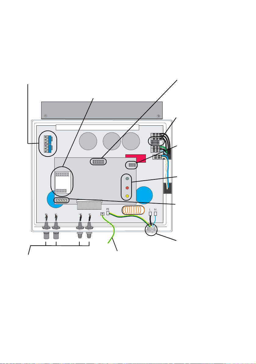
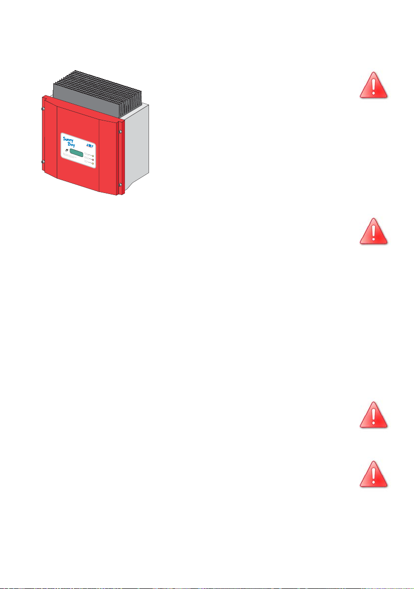
SMA Technologie AG Overview
Vari
k
3 Overview
3.1 Unit description
The following diagram gives a schematic overview of the various components and
connection points inside the Sunny Boy 700 with the lid removed:
stors
page 41
PV input plug
(DC) page 26
et for communication
Soc
(RS232, RS485, NLM PiggyBack, Radio)
PE
PE (protective
earth) connecting
cable for lid
Socket for
display unit
Terminal block for
setting the input
voltage range
Slots for setting the
input voltage range
Operating status
LEDs
Communications
N
L
connector
Connection plug
(AC) page 21
Installation Guide SB700-11:SA2006 Page 11
Page 12

Overview SMA Technologie AG
3.2 External dimensions
180 mm
Betrieb
Operation
Erdschluss
Photovoltaik-Stringwechselrichter
Photovoltaic
EarthFault
Störung
s
tring
i
nverter
Failure
322 mm
290 mm
Page 12 SB700-11:SA2006 Installation Guide
Page 13

SMA Technologie AG Installation requirements
4 Installation requirements
Please check that all of the conditions listed below are met before installing and
setting up the Sunny Boy.
4.1 Installation site requirements
The Sunny Boy 700 weighs 16 kg. Please take this weight into
account when choosing the installation site and method of
installation.
The ambient temperature must be within -25 °C to +60 °C.
The Sunny Boy 700 should be installed in a place where it is not
exposed to direct sunlight. An increased ambient temperature can
16 kg
The Sunny Boy is designed to be mounted on a vertical wall. For an optimum energy
yield and the most convenient operation, vertical installation at eye-level is
preferable. In case it is absolutely necessary to tilt the Sunny Boy to the back the
maximum angle is 45 °. If installing the unit outdoors, make sure that it is not slanting
forwards.
reduce the yield of the PV system.
It is not recommended to install the Sunny Boy lying on the back side with the lid
facing upwards.
min. 45°
Mount the Sunny Boy in a vertical position or
with a slight angle to the back.
Installation Guide SB700-11:SA2006 Page 13
Do not mount the Sunny Boy with an
angle to the front or on the back.
Page 14

Installation requirements SMA Technologie AG
When choosing the installation site, be sure to note the
following:
Unintentionally pulling out the DC plug connector under load can
damage the plug and result in bodily injury or death! Install the
Sunny Boy in such a way that it is not possible (e.g. for children) to
unplug the DC plug connector unintentionally.
Individual components in the Sunny Boy can reach a temperature
of more than 60 °C.
Do not install the Sunny Boy on flammable construction materials,
in areas where highly inflammable materials are stored or in
potentially explosive environments!
When choosing the installation site, ensure there is enough space for heat to
dissipate. Under normal conditions, the following guidelines should be applied for
the space to be kept clear around the Sunny Boy 700:
Minimum clearance
Sides 20 cm
20
cm
Top 20 cm
Underneath 20 cm
In front 5 cm
20 cm
Photovoltaik-Stringwechselrichter
Photovoltaic
Betrieb
Operation
Erdschluss
Earth
F
ault
Störung
5
s
tring
i
nverter
Failure
cm
20
cm
20 cm
In domestic installations, the unit should not be
mounted on plasterboard walls or similar as otherwise
audible vibrations are likely to result.
We recommend securing the unit to a solid surface.
The Sunny Boy 700 will emit a slight noise during
operation. This noise can be annoying when the Sunny
Boy is installed within a living area.
Page 14 SB700-11:SA2006 Installation Guide
Page 15
SMA Technologie AG Installation requirements
4.2 PV generator requirements
The Sunny Boy 700 is designed to be connected to up to two strings (PV modules
wired in series) having a homogenous structure (modules of the same type, identical
orientation, tilt and number).
The „Sunny Design“ tool will help to dimension and check the size of your string with
respect to the inverter you intend to use. Information about the „Sunny Design“ tool
is available at www.SMA.de.
The unit has four DC plug connectors (two for each string) for connecting the PV
generators. The connecting cables from the PV generators must also be fitted with this
type of plug connector. A pre-assembled set for connecting the free cable ends from
a string is available as an optional accessory. The SMA order codes for the various
connectors are as follows:
• Multi-contact 3 mm: "SWR-MC"
• Multi-contact 4 mm: "MC-SET"
• Tyco: "TYCO-SET"
Limit values for DC input
Max. voltage 250 V (DC)
Max. input current 10 A (DC)
4.3 Low voltage grid 230 V (AC)
The Sunny Boy must have a three-conductor connection to the mains (live (L), neutral
(N), protective earth (PE)).
The grid connection terminals on the AC connection
socket included in the accessories kit can take wires
with a cross-section of up to 2.5 mm². The accessories
Cable
diameter
o
11 ... 25 mm
Wire
cross-section
max. 2,5 mm²
kit also contains a PG13.5 AC connection socket for
connecting cables with a diameter between 9 mm and
13.5 mm, while the PG16 connection socket is used for
cables with a diameter up to a maximum of 17 mm. For detailed instructions, see
sections "Connecting the AC output with PG13.5" (page 22) and "Connecting the
AC plug with PG16" (page 24).
Installation Guide SB700-11:SA2006 Page 15
Page 16

Installation requirements SMA Technologie AG
We recommend using a 16 A line circuit
breaker to protect the power circuit. No
loads should be connected to this power
circuit.
Photovoltaik-Stringwechselrichter
Photovoltaic
Betrieb
Operation
Erdschluss
Earth
F
ault
Störung
stringi
nverter
Failure
16A
Rating for a line circuit breaker in a photovoltaic electrical
power unit operated in parallel with the low-voltage grid
Various factors should be taken into account when selecting line circuit breakers.
These include, for example:
• The type of cable used (conductor material and insulation)
• Ambient temperatures affect the cables (higher temperatures result in a reduced
maximum current load)
• Method of routing the cable (reduces the ampacity of the conductor)
• Bundling cables together (reduces the ampacity of the conductor)
• Loop impedance [Z] (in the event of a body contact this limits the current that can
flow and therefore determines the response behaviour of the circuit breaker)
• Adequate clearance between the circuit breakers in order to avoid excessive
heating (automatic circuit breakers trip earlier when they are warmer)
• Selectivity
• Protection class of the connected load (VDE 0100, part 410), Protection against
electric shock
Please have a look at chapter 9 "Rating for a line circuit breaker" (page 45).
1
The following standards
should be followed in all cases:
• DIN VDE 0298-4 (Cable routing and current-carrying capacity)
• DIN VDE 0100; part 430 (Protective measures; protection of cable and
cords against overcurrent)
• DIN VDE 0100; part 410 (Protective measures; protection against electric
shock)
1. The standards mentioned above are to be only used as a guideline for your
installation. They apply for installations in Germany. Please note that other
standards will apply for different countries throughout the world.
Page 16 SB700-11:SA2006 Installation Guide
Page 17

SMA Technologie AG Installation requirements
The system impedance at the installation site of the Sunny Boy 700 must be less than
1 Ohms for the islanding detection and the fuses to work porperly. In addition, we
recommend dimensioning the cable cross-section so that line losses do not exceed 1%
at the nominal power. Line losses depending on the cable length and cross-section
are shown in the graph below. It shows a multi-conduit cable with all conduits made
of copper.
1,4%
1,2%
1,0%
0,8%
0,6%
Loss
0,4%
0,2%
0,0%
0 m
Do not use cables where the losses will exceed 1.0 %.
1,5 mm²
5 m
10 m 15 m 20 m 25 m 30 m 35 m 40 m 45 m 50 m
2,5 mm²
Cable length
The maximum cable lengths for the different cable cross-sections are as follows:
Cable cross-section 1.5 mm² 2.5 mm²
Max. length 33 m 55 m
Installation Guide SB700-11:SA2006 Page 17
Page 18

Installation requirements SMA Technologie AG
The Sunny Boy 700 is designed for operation on 230 V grids and works at grid
voltages of 198 V to 260 V at 49.8 Hz to 50.2 Hz.
Limit values for AC output
Voltage range 198 V ... 260 V
Frequency range 49.8 Hz ... 50.2 Hz
Voltage range
(without MSD)
Frequency range
(without MSD)
180 V ... 260 V
45.5 Hz ... 54.5 Hz
The Sunny Boy 700 is equipped with an automatic 50 Hz / 60 Hz utility frequency
detection. It can therefore be connected to a 50 Hz or 60 Hz utility without any
further configuration changes. Pay attention to the local utility regulations in any
case.
Page 18 SB700-11:SA2006 Installation Guide
Page 19

SMA Technologie AG Installation
5 Installation
5.1 Mounting the unit
To make the job easier, we recommend you use the
supplied wall bracket to mount the Sunny Boy 700. For
vertical installation on solid concrete or block walls, for
example, you can fit the bracket using 8 mm x 50 mm
hexagon bolts to DIN 571 standard, stainless steel
type, and with wall plugs type SX8.
Betrieb
Photovoltaik-
Operation
Photovoltaic
Stringwechselrichter
s
Erdschluss
tring
i
nverter
E
arth
F
ault
Störun
g
Failure
When selecting the mounting materials, be sure to take
into account the weight of the Sunny Boy 700 (16 kg).
1. Fit the wall bracket (1). To mark the positions to
drill the holes, you can use the wall bracket as a
drilling template.
2. Now hook the Sunny Boy 700 onto the wall
bracket (2) at its upper mounting plate so that it
cannot be moved sideways.
3. Fix the Sunny Boy 700 onto its bracket by
screwing the supplied M6x10 bolt into the central
threaded hole at the bottom of the bracket (3).
4. Make sure the Sunny Boy 700 is positioned
securely on the bracket.
2
1
3
Installation Guide SB700-11:SA2006 Page 19
Page 20

Installation SMA Technologie AG
5.2 Electrical installation
Check the correct polarity before you connect the PV strings!
The complete wiring for a Sunny Boy 700 is shown schematically in the following
diagram:
16A
B
max. 2.5 mm²
Communication
String 1
String 2
Page 20 SB700-11:SA2006 Installation Guide
Page 21

SMA Technologie AG Installation
Connecting the AC output
Before you connect the mains cable to the AC connection socket,
make sure that no voltage is present at the cable.
A round plug connector system is used, which allows various cable diameters to be
used in the cable outlet. For this reason, the accessories kit includes a PG13.5
pressure screw and a PG16 pressure screw. Check which screw fitting is the right one
for your AC cable.
To connect up the AC output, follow these steps:
1. Check the grid voltage. If this is higher than
260 V, the Sunny Boy 700 will not be fully
operational. In this case, contact the local grid
operator for assistance.
The maximum grid voltage for feeding
Max. 260 V!
electricity into the grid is 260 V!
2. Isolate the grid connection (switch the line circuit
breaker to its "off" position), make sure it cannot
be switched back on, and test to make sure no
voltage is present.
Off!
1. 2. 3.
You must make sure that no voltage is
present at the AC output before opening
the Sunny Boy.
3. Now take the AC connection socket parts included in delivery of your Sunny Boy
700 and connect up the cable, with shielding and insulation stripped, as
described on the following pages:
Pressure screw
Sealing ring
for PG13.5
Threaded sleeve
Socket element
Installation Guide SB700-11:SA2006 Page 21
Cord grip
for PG13.5
for PG13.5
Pressure screw
version PG16
for large cable cross-
sections
Page 22

Installation SMA Technologie AG
Connecting the AC output with PG13.5
To connect a cable with a maximum diameter of 13.5 mm, proceed as follows.
1. Press the sealing ring into the cord grip.
Cord grip
Sealing ring
2. Now slide the pressure screw over the cable first of all, followed by the cord
grip with the sealing ring in it. Now slide the threaded sleeve over the cable.
Cord grip with
sealing ring
Threaded sleeve
Pressure screw
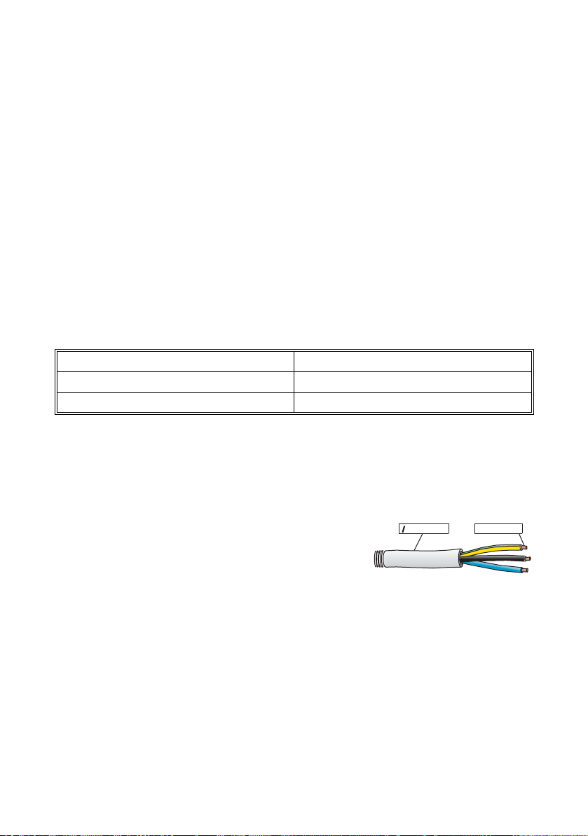
3. Now connect the individual conductors to the socket element in sequence.
- Protective earth PE (green/yellow) to the screw terminal
with the earth sign. It is required that the PE wire is
slightly longer than the L and N wires.
1
- Neutral conductor N (blue) to screw terminal 1.
2
- Live L (brown or black) to screw terminal 2.
3
- Terminal 3 remains unused.
Terminals in the socket
element
4. Make sure the wires are securely connected.
Connected wires
Pressure screw
Socket element
Threaded sleeve
Cord grip with
sealing ring
Page 22 SB700-11:SA2006 Installation Guide
Page 23

SMA Technologie AG Installation
5. Now screw the threaded sleeve onto the socket element and tighten it.
Threaded sleeve
screwed
onto socket element
Pressure screw
Cord grip with
sealing ring
6. Now screw the pressure screw into the
threaded sleeve and tighten it. The cord grip
with the sealing ring is pressed into the
threaded sleeve and can no longer be seen.
The AC connecting socket is now fully assembled.
Pressure screw
If you are not going to connect up the Sunny Boy immediately, close off the socket
element using the cap supplied in the accessories kit.
If the Sunny Boy is already installed, you can now connect up the fully assembled AC
connection socket to the flange plug on the Sunny Boy. To do this, remove the
protective cap from the flange plug on the Sunny Boy. Firmly tighten the threaded
ring on the AC connecting socket to the flange plug to seal the connection and secure
it.
Do not switch the line circuit breaker on yet! The Sunny Boy 700
may only be connected to the AC grid once the PV strings are
connected and the device is securely closed.
Installation Guide SB700-11:SA2006 Page 23
Page 24

Installation SMA Technologie AG
Connecting the AC plug with PG16
To connect a cable with a diamter between 13.5 mm and 16 mm, proceed as follows.
1. First of all, slide the pressure screw with the PG16 screw fitting onto the cable.
Now slide the threaded sleeve over the cable.
Pressure screw with
PG16 screw fitting
Threaded sleeve
2. Now connect the individual conductors to the socket element in sequence.
- Protective earth PE (green/yellow) to the screw terminal
with the earth sign. It is required that the PE wire is
slightly longer than the L and N wires.
- Neutral conductor N (blue) to screw terminal 1.
- Live L (brown or black) to screw terminal 2.
- Terminal 3 remains unused.
Terminals in the socket
3. Make sure the wires are securely connected.
3
element
1
2
Connected wires
Pressure screw with
Threaded sleeve
Socket element
PG16 screw fitting
4. Now screw the threaded sleeve onto the socket element and tighten it.
Threaded sleeve
screwed
onto socket element
Pressure screw with
PG16 screw fitting
Page 24 SB700-11:SA2006 Installation Guide
Page 25

SMA Technologie AG Installation
5. Now screw the pressure screw into into
the threaded sleeve and tighten it.
6. Firmly tighten the screw fitting against
the seal and in order to fasten the cable.
Pressure screw
PG16 screw fitting
The AC connecting socket is now fully assembled.
If you are not going to connect up the Sunny Boy immediately, close off the socket
element using the cap supplied in the accessory kit.
If the Sunny Boy is already installed, you can now connect up the fully assembled AC
connection socket to the flange plug on the Sunny Boy. To do this, remove the
protective cap from the flange plug on the Sunny Boy. Firmly tighten the threaded
ring on the AC connecting socket to the flange plug to seal the connection and secure
it.
Do not switch the line circuit breaker on yet! The Sunny Boy 700
may only be connected to the AC grid once the PV strings are
connected and the device is securely closed.
Installation Guide SB700-11:SA2006 Page 25
Page 26

Installation SMA Technologie AG
PV string (DC) connection
To connect up the input, follow these steps:
1. Check that the PV generator connectors have
the right polarity and do not exceed the
maximum string voltage of 250 V (DC). See also
section 4.2 "PV generator requirements"
(page 15).
Caution! Dangerous high voltages may be present. Danger of
death!
2. Taking one DC plug connector at a time,
measure the direct current voltage between one
DC plug connector of a string and earth
potential.
3. If the measured voltages are constant and if
their total is roughly the same as the open circuit
voltage of the string then there is a earth fault in
this string. Its approximate location can be
deduced from the relationships between the
voltages.
PE
Do not connect strings to the Sunny Boy 700 that contain a earth
fault until you have fixed the earth fault in the PV generator.
4. Repeat points 2 and 3 for each string.
5. Connect up the faultless PV generator strings to
the inverter.
6. Close off the unneeded DC input sockets using
the protective caps supplied in the accessories
kit.
Page 26 SB700-11:SA2006 Installation Guide
String 1
String 2
Page 27

SMA Technologie AG Installation
5.3 Setting the input voltage
The Sunny Boy 700 was developed for a nominal output power of 700 W. This
corresponds to a PV input voltage range of 119 ... 250 V DC at the nominal output
voltage.
For solar generators having an input voltage range of 96 ... 200 V DC or 73 ... 150
V DC it is possible to adjust the Sunny Boy 700's input voltage range accordingly. In
other words, it is also possible to connect smaller PV generators to the Sunny Boy
700.
Input voltage range Nominal output power
119 ... 250 V DC 700 W
96 ... 200 V DC 600 W
73 ... 150 V DC 460 W
For small PV systems please note:
The Sunny Boy 700 must be adjusted for the number of PV modules so that it
works in the optimum range.
Installation Guide SB700-11:SA2006 Page 27
Page 28

Installation SMA Technologie AG
The Sunny Boy 700 is factory set for the highest input voltage. To be able to use it
for smaller PV systems, you need to make some minor modifications to the unit. Inside
the Sunny Boy 700 at the top right there are a number of terminal blocks. The top
double terminal is not relevant for adjusting the input voltage range. Below the
double terminal there is a single terminal. This terminal is used to adjust the input
voltage. Below this terminal there are two free slots. You can see the input voltage
ranges associated with the slots from the drawing below.
Terminal in the slot
for
119 ... 250 V DC
Slot for
96 ... 200 V DC
Slot for
73 ... 150 V DC
The slots for the jumpers are
mounted on the Sunny Boy 700's
controller board. When supplied
from the factory, no jumper is fitted.
A jumper only needs to be used if
you want to operate the Sunny Boy
700 with a lower input voltage, i.e.
at 96 ... 200 V DC or at
73 ... 150 V DC.
Jumper slot for
96 ... 200 V DC
ENS2
200V
ENS1
150V
PE
L
Jumper slot for
73 ... 150 V DC
PE
N
N
L
Page 28 SB700-11:SA2006 Installation Guide
Page 29

SMA Technologie AG Installation
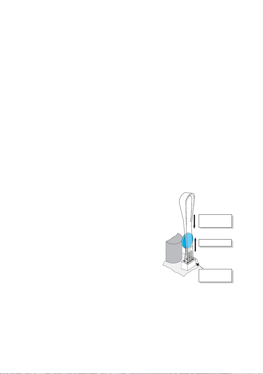
To adjust the input voltage, follow these steps:
1. Open the Sunny Boy 700 as described in section 6.1.
2. Pull the terminal upwards out of the terminal block and plug it into the
appropriate slot.
3. Plug the jumper provided in the accessories kit into the corresponding slot on the
controller board. If you want to use the Sunny Boy 700 with the maximum input
voltage range, then do not use the jumper.
4. Once the jumper is in place and the terminal plugged into the correct slot, close
the Sunny Boy 700 as described in section 6.2.
There is a schematic view of the connectors in the table below.
Voltage range Terminal block Jumper
Terminal in
slot 1
No jumper used
119 ... 250 V DC
(factory setting)
ENS2
ENS1
150V
200V
Terminal in
96 ... 200 V DC
slot 2
Terminal in
slot 3
Jumper fitted to
"200 V" position
Jumper fitted to
"150 V" position
ENS1
ENS2
200V
150V
73 ... 150 V DC
ENS2
ENS1
150V
200V
Installation Guide SB700-11:SA2006 Page 29
Page 30

Installation SMA Technologie AG
5.4 Startup
You can start up the Sunny Boy 700 when
• the lid is securely screwed on the enclosure,
• the AC (mains) cable is connected correctly,
• the DC cables (PV strings) are fully connected and the unused DC plug connectors
on the bottom of the enclosure are closed using the protective caps.
How to start up the inverter
1. First of all, switch the line circuit breaker to the
"on" position.
2. Check whether the LEDs indicate trouble-free
operation of the Sunny Boy 700 based on the
table on the next page. In that case, startup has
been successfully completed.
Photovoltaik-Stringwechselrichter
Photovoltaic
s
If the bottom yellow LED flashes four times at intervals of one
second, the grid voltage and the PV generator must be
disconnected from the Sunny Boy 700 immediately! There is a risk
of damage to the inverter resulting from excessive DC input
voltage.
On!
Off
Betrieb
Operation
Erdschluss
Earth
F
ault
Störung
tring
i
nverter
Failure
Check the string voltages again to make sure they are within the limits stated in
section 4.2 "PV generator requirements" (page 15). If the string voltages are too
high, the PV generator's planner / installer should be called upon for assistance.
If despite checking the string voltages the LED signal occurs again when the PV
generator is connected to the Sunny Boy 700, disconnect the PV generator from the
Sunny Boy again and contact SMA Technologie AG (see section 10 "Contact"
(page 49)).
Page 30 SB700-11:SA2006 Installation Guide
Page 31

SMA Technologie AG Installation
Green Red Yellow Status
off off OK (feeding grid)
on
blinking quickly
(3 x per second)
on / blinkingy
(1 x per second)
on / blinking
(shortly off 1 x
per second)
off
on
off off OK (stop)
on off failure
off off
on off failure
off off OK (derating)
on off failure
off
on
off failure
on OK (initialization)
OK (waiting, grid
monitoring)
off OK (night standby)
on / blinking failure
off failure
on / blinking failure
For a detailed description of the fault messages and their causes, see the operating
instructions.
Installation Guide SB700-11:SA2006 Page 31
Page 32

Installation SMA Technologie AG
Page 32 SB700-11:SA2006 Installation Guide
Page 33

SMA Technologie AG Opening and closing the Sunny Boy
6 Opening and closing the Sunny Boy
If you need to open the device for whatever reason, please
pay attention to section 2 "Safety information" (page 9).
6.1 Opening the Sunny Boy
Caution: Follow the sequence below under all circumstances.
1. Switch the line circuit breaker to the "off" position.
2. Disconnect the PV generator from the Sunny Boy 700.
3. Wait 30 minutes!
4. Remove the four screws from the lid and pull the lid off the enclosure. Unlock
the green-yellow PE connection and remove it from the lid and take the lid off.
6.2 Closing the Sunny Boy
Caution: Follow the sequence below under all circumstances.
1. Reconnect the earth wire (PE) to the lid. Now secure the lid to the Sunny Boy
700 by tightening the four screws evenly.
2. Connect the PV generator.
3. Switch the line circuit breaker to the "on" position.
4. Now check whether the LED display on the Sunny Boy 700 indicates that the
device is functioning correctly.
Installation Guide SB700-11:SA2006 Page 33
Page 34

Opening and closing the Sunny Boy SMA Technologie AG
Page 34 SB700-11:SA2006 Installation Guide
Page 35

SMA Technologie AG Technical data
7 Technical data
7.1 Input voltage range 119 ... 250 V DC
7.1.1 PV generator connection data
Max. input open circuit voltage U
PV 0
250 V
(based on -10 °C cell temperature)
Input voltage, MPP range U
Max. input current I
Max. input power P
PV max
PV
DC
119 V ... 250 V
7 A
780 W
Recommended generator power 900 Wp
All-pole isolator on the DC input side
DC plug connector
Overvoltage protection Thermally monitored varistors
Voltage ripple U
< 10 % of the input voltage
pp
Insulation protection Ground fault monitoring
(Riso > 1 MΩ)
Operating consumption < 4 W (standby)
Reverse polarity protection Short circuit diode
7.1.2 Grid connection data
Nominal output power P
Peak output power P
Nominal output current I
Harmonic distortion of output current
(at K
< 2 %, PAC > 0.5 P
Ugrid
AC nom
AC nom
K
)
Short-circuit strength Grid-side via current regulation
Operating range, grid voltage U
Operating range, grid frequency f
AC
All-pole isolation on grid side Independent disconnection device
Phase shift angle (based on the
current's fundamental frequency) cos phi 1
Overvoltage category III
Test voltage (50 Hz) 1.3 kV (1 s routine testing / 5 s type
Test surge voltage 4 kV (serial interface: 6 kV)
Own consumption in night mode 0.1 W
700 W
AC nom
700 W
ACm ax
3 A
< 3 %
IAC
198 ... 260 V AC
AC
49.8 ... 50.2 Hz
(MSD), redundant design
testing)
Installation Guide SB700-11:SA2006 Page 35
Page 36

Technical data SMA Technologie AG
7.2 Input voltage range 96 ... 200 V DC
7.2.1 PV generator connection data
Max. input open circuit voltage U
250 V (based on -10 °C cell
PV 0
temperature)
Input voltage, MPP range U
Max. input current I
Max. input power P
PV max
PV
DC
96 V ... 200 V
7 A
670 W
Recommended generator power 750 Wp
All-pole isolator on the DC input side
DC plug connector
Overvoltage protection Thermally monitored varistors
Voltage ripple U
< 10 % of the input voltage
pp
Insulation protection Ground fault monitoring
(Riso > 1 MΩ)
Operating consumption < 4 W (standby)
Reverse polarity protection Short circuit diode
7.2.2 Grid connection data
Nominal output power P
Peak output power P
Nominal output current I
Harmonic distortion of output current
(at K
< 2 %, PAC > 0.5 P
Ugrid
AC nom
ACnom
K
)
Short-circuit strength Grid-side via current regulation
Operating range, grid voltage U
Operating range, grid frequency f
AC
All-pole isolation on grid side Independent disconnection device
Phase shift angle (based on the
current's fundamental frequency) cos phi 1
Overvoltage category III
Test voltage (50 Hz) 1.3 kV (1 s routine testing / 5 s type
Test surge voltage 4 kV (serial interface: 6 kV)
Own consumption in night mode 0.1 W
600 W
AC nom
600 W
ACm ax
2.6 A
< 3 %
IAC
198 ... 260 V AC
AC
49.8 ... 50.2 Hz
(MSD), redundant design
testing)
Page 36 SB700-11:SA2006 Installation Guide
Page 37

SMA Technologie AG Technical data
7.3 Input voltage range 73 ... 150 V DC
7.3.1 PV generator connection data
Max. input open circuit voltage U
250 V (based on -10 °C cell
PV 0
temperature)
Input voltage, MPP range U
Max. input current I
Max. input power P
PV max
PV
DC
73 V ... 150 V
7 A
510 W
Recommended generator power 600 Wp
All-pole isolator on the DC input side
DC plug connector
Overvoltage protection Thermally monitored varistors
Voltage ripple U
< 10 % of the input voltage
pp
Insulation protection Ground fault monitoring
(Riso > 1 MΩ)
Operating consumption < 4 W (standby)
Reverse polarity protection Short circuit diode
7.3.2 Grid connection data
Nominal output power P
Peak output power P
Nominal output current I
Harmonic distortion of output current
(at K
< 2 %, PAC > 0.5 P
Ugrid
AC nom
ACnom
K
)
Short-circuit strength Grid-side via current regulation
Operating range, grid voltage U
Operating range, grid frequency f
AC
All-pole isolation on grid side Independent disconnection device
Phase shift angle (based on the current's
fundamental frequency) cos ϕ 1
Overvoltage category III
Test voltage (50 Hz) 1.3 kV (1 s routine testing / 5 s type
Test surge voltage 4 kV (serial interface: 6 kV)
Own consumption in night mode 0.1 W
460 W
AC nom
460 W
ACm ax
2 A
< 3 %
IAC
198 ... 260 V AC
AC
49.8 ... 50.2 Hz
(MSD), redundant design
testing)
Installation Guide SB700-11:SA2006 Page 37
Page 38

Technical data SMA Technologie AG
7.4 Device description
For a detailed description of the device, see the operating instructions.
General data
Protection category per DIN EN 60529 IP65
Dimensions (w x h x d)
Weight 16 kg (approx.)
External interfaces
Data transmission over mains power line Optional
Data transmission over separate data cable Optional,
Wireless data transmission Optional
Efficiency
Max. efficiency η
European standard efficiency η
The efficiency of the Sunny Boy 700 depends mainly on the input voltage of the
connected PV strings. The lower the input voltage, the higher is the efficiency of the
Sunny Boy 700.
max
euro
322 mm x 290 mm x 180 mm
(approx.)
RS232 / RS485, electrically separated
93.4 %
92 %
100
90
80
70
Overall efficiency [%]
60
50
Sunny Boy 700
40
01020304050 7060 80 90 100
Output power [%]
Page 38 SB700-11:SA2006 Installation Guide
Page 39

SMA Technologie AG Technical data
7.5 Operating parameters
Unauthorised changes to the operating parameters may result
in:
• Injury or accidents as a result of changing the internal
safety routines in the Sunny Boy
• Voiding the Sunny Boy's operating approval certificate
• Voiding the Sunny Boy's guarantee
Never change the parameters of your Sunny Boy without
express authorization and instructions.
The parameters with a grey background are only visible when in installer mode.
Name Unit Value range Factory setting
Betriebsart /
Operating mode
Default GER/ENS
dFac-Max Hz/s 0.005 ... 4.0 0.5
dZac-Max mOhm 0 ... 20000 350
E_Total kWh 0 ... 200000
Fac-Delta- Hz 0 ... 4.5 0.19
Fac-Delta+ Hz 0 ... 4.5 0.19
h_Total h 0 ... 200000
I-NiTest /
Testcurrent Zac
Speicherfunktion /
Memory function
Speicher/Storage Permanent, volatile Permanent
T-Start s 5 ... 300 10
T-Stop s 1 ... 3600 2
Uac-Min / Vac-Min V 180 ... 300 198
Uac-Max / Vac-Max V 180 ... 300 260
Upv-Start /
Vpv-Start
Usoll-Konst /
Vconst-Setpoint
mA 0 ... 6000 4500/
V 125 ... 250/
V 125 ... 330/
MPP, IKonst, UKonst, Stopp, Turbine
Mode, Insel Mode
Default Parameter, Reset Betriebsdaten,
Reset Fehler
100 ... 200/
75 ... 150
100 ... 330/
75 ... 330
MPP
4000/
3500
none
150/
125/
95
275/
275/
275
Installation Guide SB700-11:SA2006 Page 39
Page 40

Technical data SMA Technologie AG
The following parameters are displayed in the parameter list but cannot be changed:
Name Unit Value range Description
Plimit W 700/
600/
460
SMA-SN Serial number of the Sunny Boy
Software-BFR /
Firmware BFR
Software-SRR /
Firmware SRR
Upper limit for AC output power
Firmware version of the operation control unit (BFR)
Firmware version of the current control unit (SRR)
Page 40 SB700-11:SA2006 Installation Guide
Page 41

SMA Technologie AG Replacing the varistors
8 Replacing the varistors
The Sunny Boy 700 is a complex high-technology device. As a result, the possibilities
for fixing faults on site are limited to just a few items. Please don't try to carry out
repairs other than those described here. Use the SMA Technologie AG 24-hour
exchange service and repair service instead.
If the red LED on the status display glows continuously during operation, you should
first of all make sure that there is no earth fault in the PV generator.
1. Disconnect the Sunny Boy 700 from the low
voltage grid (pull out the AC plug or switch the
line circuit breaker to its "off" position). Make
sure the grid cannot be inadvertently
reconnected.
2. Disconnect the DC plug connectors for all
strings. Make sure you note the order of the
individual inverter inputs so you can put them
back in the right place later!
3. Taking one DC plug connector at a time,
measure the voltages between one DC plug
connector of a string and earth potential. Pay
attention to the safety warnings!
Off!
1. 2. 3.
You must make sure that no voltage is
present at the AC output before opening
String 1
String 2
Disconnect the PV generators from the
the Sunny Boy.
Sunny Boy.
PE
Measure the voltage between DC plug
connectors and earth potential.
Caution! Dangerous high voltages may be present. Danger of
death!
4. If the measured voltages are constant and if their total is roughly the same as
the open circuit voltage of the string then there is a earth fault in this string. Its
approximate location can be deduced from the relationships between the
voltages.
Installation Guide SB700-11:SA2006 Page 41
Page 42
Replacing the varistors SMA Technologie AG
5. Repeat points 3 and 4 for each string.
If you found a earth fault, it is probably not necessary to replace the varistors.
Instead, make sure the ground fault is fixed. Generally the PV generator's
installation engineer should be hired for this job. In this case continue as
described under point 10, but without reconnecting the faulty string. Instead of
reconnecting the string, protect its DC plug against accidental touch contact
(e.g. by fitting the protective caps or using sufficient high-voltage insulating
tape).
If you did not find any earth fault in the PV generators, it is likely that one of the
thermally monitored varistors has lost its protective function. These components
are wearing parts. Their functioning diminishes with age or following repeated
responses as a result of overvoltages. You can now check these varistors in the
following way, paying attention to the safety information in section 2 "Safety
information" (page 9):
6. Remove the screws that secure the lid and remove the lid from the Sunny Boy
700. Disconnect the PE connection from the lid. Make sure that no voltage is
present.
7. Using a continuity tester, check all the varistors to see if there is a conducting
connection between connectors 2 and 3. If there isn't, then that varistor is not
working. The positions of the varistors in the Sunny Boy 700 can be seen in
section 3.1 "Unit description" (page 11).
8. Replace the varistor concerned with a new one
as shown in the drawing to the right. Ensure the
varistor is installed the right way round! If you
do not receive a special tool for operating the
terminal clamps with your replacement
Insert the special tool to open
the terminal clamp.
varistors, please contact SMA. As an
alternative, the terminal contacts can be
operated using a suitable screwdriver. Since the
Remove the varistor.
failure of one varistor is generally due to factors
that affect all varistors in a similar way
(temperature, age, inductive overvoltages), it is
highly recommended that you replace both
varistors, not just the one that is obviously
defective. The varistors were specially
3 21
The pole with the small loop
(crimp) must be fitted to
terminal 1 when replacing the
varistor.
manufactured for use in the Sunny Boy 700 and
are not commercially available. They must be
ordered directly from SMA Technologie AG
(SMA order code: SB-TV1).
Page 42 SB700-11:SA2006 Installation Guide
Page 43

SMA Technologie AG Replacing the varistors
In case there are no spare varistors available the Sunny Boy 700
still can feed electricity into the grid. The input is not protected
against overvoltages in this case. Replacement varistors should be
obtained as soon as possible. In systems with a high risk of
overvoltages, the Sunny Boy 700 should not be operated with
defective varistors.
9. Reconnect the PE connection on the lid and close the Sunny Boy 700.
10. Connect up the faultless PV generator strings to
the inverter.
11. Close off the unneeded DC input sockets using
the protective caps supplied in the accessories
kit.
String 1
String 2
12. Switch the line circuit breaker to the "on"
position.
On!
13. Now check whether the LED display on the
Sunny Boy 700 indicates that the device is
functioning correctly.
Off
If no earth fault and no defective varistor were found, there is probably a fault in the
Sunny Boy. In this case, contact the SMA hotline to discuss what to do next.
Installation Guide SB700-11:SA2006 Page 43
Page 44

Replacing the varistors SMA Technologie AG
Page 44 SB700-11:SA2006 Installation Guide
Page 45

SMA Technologie AG Rating for a line circuit breaker
9 Rating for a line circuit breaker
Example for the thermal rating for a line circuit breaker in a photovoltaic
electrical power unit operated in parallel with the low-voltage grid
We assume a PV system with 9 Sunny Boy 700 inverters, with three inverters
per phase.
SB1100
Be
t
rie
P
h
b
otovolta
Operation
Ph
i
o
k
-
tovo
S
t
ring
l
taic
w
ech
s
trin
s
Erd
el
g
r
ichter
s
i
n
chlu
v
erter
ss
E
a
r
t
h
F
a
u
lt
S
t
öru
ng
Fail
u
re
L1
L2
L3
SB1100
Betr
Ph
i
eb
otov
Operation
o
lta
Ph
i
otov
k-St
ri
ol
ngwech
ta
i
c
s
t
ri
s
Er
n
el
g
d
ri
sc
i
ch
nv
hlu
t
ert
er
ss
E
er
a
rth
F
a
u
l
t
S
t
ör
ung
Fail
u
re
SB1100
Be
t
rie
P
ho
b
t
o
Opera
vo
l
Pho
t
a
ik-
t
ion
tov
S
tri
o
n
l
t
gwe
a
i
c
c
s
tr
hselri
i
Erd
ng
s
i
c
nv
chlu
hter
ert
ss
Ear
er
t
h
F
ault
S
t
öru
ng
Failure
...
SB1100
Be
t
r
Pho
i
e
b
t
o
Op
v
ol
e
Photovol
ta
r
a
i
k
t
-Strin
i
o
n
t
g
aic
w
ech
s
t
r
s
ing
Er
el
dschluss
ri
i
ch
nv
t
e
er
rter
Ea
rt
h
F
ault
S
t
örung
F
a
il
u
r
e
SB1100
Be
t
rie
P
h
b
o
t
ov
Ope
olt
Pho
aik-
r
ati
t
o
o
Stri
n
v
ol
n
ta
g
wec
i
c
s
tr
hse
i
Erd
ng
l
ri
s
i
c
nv
chlu
hte
ert
r
ss
Eart
er
h
F
a
u
l
t
Störun
g
Fa
il
u
r
e
SB1100
Be
t
r
Pho
i
e
b
t
o
Op
v
ol
e
Photovoltaic
t
ai
rat
k
-Strin
i
o
n
g
w
ech
s
tring
selric
E
rds
i
nverter
c
h
hluss
t
er
Ea
rt
h
F
ault
S
t
örung
F
a
il
u
r
e
N
Required technical information for the inverters used:
• Maximum output current = 3.5 A
• Maximum permissible fuse protection for the inverter = 16 A
The choice of cable together with the way it is routed, ambient temperatures and
other underlying conditions limit the maximum fuse protection for the cable.
• In our example we assume that the chosen cable (2.5 mm²) is ideally routed and
can take a nominal current of 11 A.
Selecting a line circuit breaker:
• The maximum possible nominal current for the cable used and the maximum
possible fuse protection for the inverter now limit the maximum possible nominal
current for the line circuit breaker.
• In our example, 10 A is possible.
However, the thermal suitability of the line circuit breaker still needs to be checked.
Installation Guide SB700-11:SA2006 Page 45
Page 46

Rating for a line circuit breaker SMA Technologie AG
When selecting line circuit breakers, a number of load factors need to be taken into
account. These can be found in the respective data sheets.
Example for the thermal selection of a 10 A line circuit breaker with B sensitivity
with no gap between the circuit breakers:
For example, one manufacturer's circuit breaker may be designed for an ambient
temperature of 50 °C.
Load factors according to data sheet specifications:
• Reduction through permanent load >1h = 0.9
• Reduction when 9 circuit breakers are arranged side-by-side without
gaps = 0.77
• Increase in nominal current as a result of ambient temperatures of 40 °C in the
circuit breaker panel = 1.07
2
3
1
Result:
The nominal load current for the line circuit breaker is calculated as:
Ibn = 10 A x 0.9 x 0.77 x 1.07 = 7.4 A
1. Permanent loads of longer than 1 hour are possible in photovoltaics.
2. When only one circuit breaker is used, this factor = 1
3. Because the circuit breakers are rated for 50 °C
Page 46 SB700-11:SA2006 Installation Guide
Page 47

SMA Technologie AG Rating for a line circuit breaker
Summary:
The selected line circuit breaker can be used in our example case since the maximum
current-carrying capacity for fault-free operation is higher than the maximum output
current of the inverter used. It will trip under rated operating conditions!
If the calculated current-carrying capacity of the circuit breaker had been lower than
the maximum output current from the inverter, the following solution might have been
used:
By spacing the circuit breakers at an interval of 8 mm, the reduction factor would be
0.98 instead of 0.77. As a result, the maximum current-carrying capacity would
increase to 9.4 A.
As well as the thermal rating of the circuit breakers and all other factors as specified
in section "Rating for a line circuit breaker in a photovoltaic electrical power unit
operated in parallel with the low-voltage grid" (page 16), of course the applicable
DIN VDE standards
here are:
• DIN VDE 0100; part 410
• DIN VDE 0100; part 430
• DIN VDE 0298; part 4
In special applications the relevant standards must be followed.
1
also need to be taken into account. The main ones that apply
1. The standards mentioned above are to be only used as a guideline for your
installation. They apply for installations in Germany. Please note that other
standards will apply for different countries throughout the world.
Installation Guide SB700-11:SA2006 Page 47
Page 48

Rating for a line circuit breaker SMA Technologie AG
Page 48 SB700-11:SA2006 Installation Guide
Page 49

SMA Technologie AG Contact
10 Contact
If you have any questions or technical problems concerning the Sunny Boy 700,
please contact our hotline. Please have the following information available when you
contact SMA:
• Inverter type
• Type and number of connected modules
• Communication method
• Serial number of the Sunny Boy
Address:
SMA Technologie AG
Hannoversche Strasse 1 - 5
34266 Niestetal
Germany
Tel.:+49 (0)561 95 22 - 499
Fax:+49 (0)561 95 22 - 4699
hotline@SMA.de
www.SMA.de
Installation Guide SB700-11:SA2006 Page 49
Page 50

Contact SMA Technologie AG
Page 50 SB700-11:SA2006 Installation Guide
Page 51

Page 52

www.SMA.de
SM
A
Technologie AG
5
l
G
y
0
e
a
ld
hil
t
a
5
i
4
ll
A
M
m
k
f
k
V
n
lano
ly
b
l
7
a
S
n
3
Hannoversche Straße 1–
34266 Niesteta
erman
Tel. +49 561 9522
info@SMA.d
SMA Technologie AG
SMA Solartechnology Chin
International Metro Center,
ing A, City Square No. Jia 3,
Bui
ipu Road, Changyang Distric
S
100025 Beijing, PR. Chin
Tel. +86 10 65 58 78 1
www.SMA-CHINA.com
SMA Amer
12
Grass Va
Tel. +1 530 273 4895
www.S
ca, Inc.
38 Loma Rica Drive, Unit C
ey, CA 95945, US
A-AMERICA.co
ertrieb SMA Italie
Via Lorenzo Valla, 16
20141 Mi
Ita
Tel. +39 02 847421
SMA Spanien
Vertrie
mes, 29
Ba
08006 Barcelon
pai
Tel. +34 639 40368
Innovation in Systemtechni
Page 52 SB700-11:SA2006 Installation Guide
ür den Erfolg der Photovoltai
 Loading...